US8422540B1 - Intelligent backhaul radio with zero division duplexing - Google Patents
Intelligent backhaul radio with zero division duplexingDownload PDFInfo
- Publication number
- US8422540B1 US8422540B1US13/609,156US201213609156AUS8422540B1US 8422540 B1US8422540 B1US 8422540B1US 201213609156 AUS201213609156 AUS 201213609156AUS 8422540 B1US8422540 B1US 8422540B1
- Authority
- US
- United States
- Prior art keywords
- signals
- baseband
- receive
- cancellation
- transmit
- Prior art date
- Legal status (The legal status is an assumption and is not a legal conclusion. Google has not performed a legal analysis and makes no representation as to the accuracy of the status listed.)
- Expired - Fee Related
Links
Images


Classifications
- H—ELECTRICITY
- H04—ELECTRIC COMMUNICATION TECHNIQUE
- H04L—TRANSMISSION OF DIGITAL INFORMATION, e.g. TELEGRAPHIC COMMUNICATION
- H04L5/00—Arrangements affording multiple use of the transmission path
- H04L5/14—Two-way operation using the same type of signal, i.e. duplex
- H04L5/1423—Two-way operation using the same type of signal, i.e. duplex for simultaneous baseband signals
- H—ELECTRICITY
- H01—ELECTRIC ELEMENTS
- H01Q—ANTENNAS, i.e. RADIO AERIALS
- H01Q21/00—Antenna arrays or systems
- H01Q21/06—Arrays of individually energised antenna units similarly polarised and spaced apart
- H01Q21/061—Two dimensional planar arrays
- H01Q21/062—Two dimensional planar arrays using dipole aerials
- H—ELECTRICITY
- H01—ELECTRIC ELEMENTS
- H01Q—ANTENNAS, i.e. RADIO AERIALS
- H01Q21/00—Antenna arrays or systems
- H01Q21/24—Combinations of antenna units polarised in different directions for transmitting or receiving circularly and elliptically polarised waves or waves linearly polarised in any direction
- H—ELECTRICITY
- H01—ELECTRIC ELEMENTS
- H01Q—ANTENNAS, i.e. RADIO AERIALS
- H01Q21/00—Antenna arrays or systems
- H01Q21/28—Combinations of substantially independent non-interacting antenna units or systems
- H—ELECTRICITY
- H04—ELECTRIC COMMUNICATION TECHNIQUE
- H04B—TRANSMISSION
- H04B1/00—Details of transmission systems, not covered by a single one of groups H04B3/00 - H04B13/00; Details of transmission systems not characterised by the medium used for transmission
- H04B1/38—Transceivers, i.e. devices in which transmitter and receiver form a structural unit and in which at least one part is used for functions of transmitting and receiving
- H04B1/40—Circuits
- H04B1/50—Circuits using different frequencies for the two directions of communication
- H04B1/52—Hybrid arrangements, i.e. arrangements for transition from single-path two-direction transmission to single-direction transmission on each of two paths or vice versa
- H04B1/525—Hybrid arrangements, i.e. arrangements for transition from single-path two-direction transmission to single-direction transmission on each of two paths or vice versa with means for reducing leakage of transmitter signal into the receiver
- H—ELECTRICITY
- H04—ELECTRIC COMMUNICATION TECHNIQUE
- H04B—TRANSMISSION
- H04B1/00—Details of transmission systems, not covered by a single one of groups H04B3/00 - H04B13/00; Details of transmission systems not characterised by the medium used for transmission
- H04B1/38—Transceivers, i.e. devices in which transmitter and receiver form a structural unit and in which at least one part is used for functions of transmitting and receiving
- H04B1/40—Circuits
- H04B1/54—Circuits using the same frequency for two directions of communication
- H—ELECTRICITY
- H04—ELECTRIC COMMUNICATION TECHNIQUE
- H04B—TRANSMISSION
- H04B15/00—Suppression or limitation of noise or interference
- H—ELECTRICITY
- H04—ELECTRIC COMMUNICATION TECHNIQUE
- H04L—TRANSMISSION OF DIGITAL INFORMATION, e.g. TELEGRAPHIC COMMUNICATION
- H04L5/00—Arrangements affording multiple use of the transmission path
- H04L5/14—Two-way operation using the same type of signal, i.e. duplex
- H04L5/1461—Suppression of signals in the return path, i.e. bidirectional control circuits
- H—ELECTRICITY
- H04—ELECTRIC COMMUNICATION TECHNIQUE
- H04W—WIRELESS COMMUNICATION NETWORKS
- H04W24/00—Supervisory, monitoring or testing arrangements
- H04W24/02—Arrangements for optimising operational condition
Definitions
- the present disclosurerelates generally to data networking and in particular to a backhaul radio for connecting remote edge access networks to core networks with advantageous spectrum usage.
- WLANwireless local area network
- cellular base stations or WLAN access pointsinevitably become very high data bandwidth demand points that require continuous connectivity to an optical fiber core network.
- microwave radios 132for backhaul have been mounted on high towers 112 (or high rooftops of multi-story buildings) as shown in FIG. 1 , such that each microwave radio 132 has an unobstructed line of sight (LOS) 136 to the other.
- LOSline of sight
- These microwave radios 132can have data rates of 100 Mb/s or higher at unobstructed LOS ranges of 300 m or longer with latencies of 5 ms or less (to minimize overall network latency).
- Traditional microwave backhaul radios 132operate in a Point to Point (PTP) configuration using a single “high gain” (typically >30 dBi or even >40 dBi) antenna at each end of the link 136 , such as, for example, antennas constructed using a parabolic dish.
- high gain antennasmitigate the effects of unwanted multipath self-interference or unwanted co-channel interference from other radio systems such that high data rates, long range and low latency can be achieved.
- These high gain antennashowever have narrow radiation patterns.
- microwave backhaul radios 132require very precise, and usually manual, physical alignment of their narrow radiation patterns in order to achieve such high performance results. Such alignment is almost impossible to maintain over extended periods of time unless the two radios have a clear unobstructed line of sight (LOS) between them over the entire range of separation. Furthermore, such precise alignment makes it impractical for any one such microwave backhaul radio to communicate effectively with multiple other radios simultaneously (i.e., a “point to multipoint” (PMP) configuration).
- PMPpoint to multipoint
- “street level” deployment of cellular base stations, WLAN access points or LAN gatewayssuffers from problems because there are significant obstructions for LOS in urban environments (e.g., tall buildings, or any environments where tall trees or uneven topography are present).
- FIG. 1illustrates edge access using conventional unobstructed LOS PTP microwave radios 132 .
- the scenario depicted in FIG. 1is common for many 2 nd Generation (2G) and 3 rd Generation (3G) cellular network deployments using “macrocells”.
- a Cellular Base Transceiver Station (BTS) 104is shown housed within a small building 108 adjacent to a large tower 112 .
- the cellular antennas 116 that communicate with various cellular subscriber devices 120are mounted on the towers 112 .
- the PTP microwave radios 132are mounted on the towers 112 and are connected to the BTSs 104 via an nT1 interface. As shown in FIG. 1 by line 136 , the radios 132 require unobstructed LOS.
- the BTS on the right 104 ahas either an nT1 copper interface or an optical fiber interface 124 to connect the BTS 104 a to the Base Station Controller (BSC) 128 .
- the BSC 128either is part of or communicates with the core network of the cellular network operator.
- the BTS on the left 104 bis identical to the BTS on the right 104 a in FIG. 1 except that the BTS on the left 104 b has no local wireline nT1 (or optical fiber equivalent) so the nT1 interface is instead connected to a conventional PTP microwave radio 132 with unobstructed LOS to the tower on the right 112 a .
- the nT1 interfaces for both BTSs 104 a , 104 bcan then be backhauled to the BSC 128 as shown in FIG. 1 .
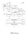
- FIG. 2depicts a generic digital radio, not necessarily a conventional PTP radio or an IBR, in a TDD configuration.
- TDDtime division duplexing
- only one of the radios amongst the two peers depicted in FIG. 2transmits at any given point in time according to a time schedule known to both radios. This enables both TDD radios to transmit and receive at the same frequency or within the same finite frequency band.
- each radiotransmits and receives at a single nominal carrier frequency f 1 , but when one radio in any given link (of which only one link is depicted in FIG. 2 ) is transmitting, then the other radio is receiving wherein neither radio transmits and receives at the same point in time.
- FIG. 3depicts a generic digital radio, not necessarily a conventional PTP radio or an IBR, in a conventional FDD configuration.
- FDDfrequency division duplexing
- TDD antenna resourcesare easily shared between transmit and receive, which is a distinct advantage for TDD.
- FDD antenna resourcesare not easily shared and either separate antennas for transmit and receive or a frequency duplexer is required to support conventional FDD radio operation.
- TDDtime division duplex
- FDD antenna resourcesare not easily shared and either separate antennas for transmit and receive or a frequency duplexer is required to support conventional FDD radio operation.
- TDDthe isolation of the receiver from the intentional or unintentional signals of the transmitter is straightforward since transmission occurs only when reception does not occur, and vice versa.
- the transmitter signalsboth intentional and unintentional
- the transmitter signalsmust be highly isolated from the receiver channel, which is a disadvantage for FDD such that conventional FDD radios have required multiple additional filters relative to TDD as well as separate antennas or frequency duplexers.
- non-antennaresources, such as the entire transmit path and the entire receive path are utilized at all times.
- much or all of the transmit pathmay be idle when receiving and vice versa for the receive path when transmitting, which significantly underutilizes the resources within a TDD radio.
- a low latency feedback channel to each transmitteris available because a peer FDD radio does not need to wait until such transmitter stops transmitting to send feedback information that may enhance the link performance.
- no feedbackcan occur until the transmitter stops and the radio goes to receive mode and thus feedback latency must also be traded off against overall efficiency.
- each radio in a particular linktransmits and receives at single nominal carrier frequency f 1 as is allowable for TDD, but can transmit and receive simultaneously as is allowable for FDD
- ZDDZiero Division Duplexing
- a ZDD radio in theorycan have at least twice the single-link spectral efficiency of either an FDD or TDD radio by utilizing the same frequency channel simultaneously in both directions of a link.
- ZDD operationmay be at two channels about a nominal frequency f 1 such that no conventional isolation filtering at RF is possible in which case the above referenced advantages still apply except for the spectral efficiency improvement.
- exemplary ZDD radioshave attempted to cancel unwanted transmitter leakage primarily by inverting the phase of an attenuated copy of the transmit signal and summing it at the receiver to substantially cancel the transmit signal leakage at the receiver antenna.
- Some embodiments of the claimed inventionare directed to backhaul radios utilizing zero division duplexing (ZDD) that are compact, light and low power for street level mounting, operate at 100 Mb/s or higher at ranges of 300 m or longer in obstructed LOS conditions with low latencies of 5 ms or less, can support PTP and PMP topologies, use radio spectrum resources efficiently and do not require precise physical antenna alignment. Radios with such exemplary capabilities as described by multiple various embodiments are referred to herein by the term “Intelligent Backhaul Radio” (IBR).
- IBRIntelligent Backhaul Radio
- an intelligent backhaul radioincludes a plurality of transmit RF chains to convert from a plurality of transmit chain input signals to a plurality of respective RF transmit chain signals; a plurality of adaptable RF transversal filter sets to convert a plurality of signals respectively derived from the plurality of RF transmit chain signals to a plurality of RF transmit leakage cancellation signals, wherein each adaptable RF transversal filter set is comprised of a plurality of adaptable RF transversal filters, each for filtering a respective one of said plurality of signals respectively derived from the plurality of RF transmit chain signals to provide a respective adaptable RF transversal filtered signal, and a combiner for combining the plurality of adaptable RF transversal filtered signals within the filter set to produce one of said RF transmit leakage cancellation signals; a plurality of RF cancellation combiners for respectively combining one of said plurality of RF transmit leakage cancellation signals with one of said plurality of RF receive signals to provide a plurality of RF transmit leakage cancellation signals
- an intelligent backhaul radioincludes a plurality of transmit RF chains to convert from a plurality of transmit chain input signals to a plurality of respective RF transmit chain signals; a plurality of adaptable RF transversal filter sets to convert a plurality of signals respectively derived from the plurality of RF transmit chain signals to a plurality of RF transmit leakage cancellation signals, wherein each adaptable RF transversal filter set is comprised of a plurality of adaptable RF transversal filters, each for filtering a respective one of said plurality of signals respectively derived from the plurality of RF transmit chain signals to provide a respective adaptable RF transversal filtered signal, and a combiner for combining the plurality of adaptable RF transversal filtered signals within the filter set to produce one of said RF transmit leakage cancellation signals; a plurality of RF cancellation combiners for respectively combining one of said plurality of RF transmit leakage cancellation signals with one of said plurality of RF receive signals to provide a plurality of RF transmit leakage cancellation signals
- the transmit leakage metricis an RSSI measurement.
- the transmit leakage metricis further derived from said receive chain output signal, wherein the derivation of said RF transmit leakage metric comprises a correlation with one or more signals related to one or more of said transit chain input signals.
- the adapting by said cancellation controller of each of the plurality of adaptable RF transversal filters of one or more of said plurality of adaptable RF transversal filter setsutilizes an iterative adaptation algorithm so as to minimize or otherwise optimize said wherein said RF transmit leakage metrics.
- the baseband cancellation adaptation input signalsare respectively derived said baseband cancelled receive signals.
- the baseband cancellation adaptation input signalsare respectively derived utilizing a correlation with one or more signals related to one or more of said transit chain input signals, and wherein said adapting by said cancellation controller of each of the plurality of adaptable baseband transversal filters of one or more of said plurality of adaptable baseband transversal filter sets utilizes an iterative adaptation algorithm so as to minimize any remaining transmit leakage signal from the baseband cancelled receive signals.
- the baseband cancellation adaptation input signalscomprise signals related said transit chain input signals, and further comprise one or more of said receive chain output signals, and wherein said adapting by said cancellation controller of each of the plurality of adaptable baseband transversal filters of one or more of said plurality of adaptable baseband transversal filter sets utilizes a closed form calculation utilizing said baseband cancellation adaptation input signals.
- the closed form calculationinvolves a least squares or MMSE calculations.
- the combiner of one or more of said adaptable RF transversal filter setsis integral to one or more of said RF cancellation combiners.
- the combiner of one or more of said adaptable baseband transversal filter setsis integral to one or more of said receive baseband cancellation combiners.
- an intelligent backhaul radioincludes a plurality of transmit RF chains to convert from a plurality of transmit chain input signals to a plurality of respective RF transmit chain signals; a plurality of transmit RF reference receive chains respectively coupled, directly or indirectly, to the output of said plurality of transmit RF chains, to convert a plurality of signals respectively derived from said respective RF transmit chain signals to respective baseband sampled RF transmit reference signals; a plurality of receive baseband cancellation combiners for combining a plurality of baseband sampled RF transmit leakage cancellation signals with a respective one of a plurality of receive chain output signals to provide a plurality of baseband cancelled receive signals; a plurality of first adaptable baseband transversal filter sets to receive the plurality of baseband sampled RF transmit reference signals and provide a plurality of baseband sampled RF transmit leakage cancellation signals respectively to each of the plurality of respective receive baseband cancellation combiners, wherein each first adaptable baseband transversal filter set is comprised of a
- the second RF transmit leakage metricis an RSSI measurement.
- the second RF transmit leakage metricis further derived from said receive chain output signal, wherein the derivation of said first or said second RF transmit leakage metric comprises a correlation with one or more signals related to one or more of said transit chain input signals.
- the adapting by said cancellation controller of each of the plurality of first or second adaptable RF transversal filters of one or more of said plurality of first or second adaptable RF transversal filter setsutilizes an iterative adaptation algorithm so as to minimize or otherwise optimize said RF transmit leakage metrics.
- the baseband cancellation adaptation input signalsare respectively derived said baseband cancelled receive signals.
- the baseband cancellation adaptation input signalsare respectively derived utilizing a correlation with one or more signals related to one or more of said transit chain input signals, and wherein said adapting by said cancellation controller of each of the plurality of second adaptable baseband transversal filters of one or more of said plurality of second adaptable baseband transversal filter sets utilizes an iterative adaptation algorithm so as to minimize any remaining transmit leakage signal from the baseband cancelled receive signals.
- the baseband cancellation adaptation input signalscomprise signals related said transit chain input signals, and further comprise one or more of said receive chain output signals, and wherein said adapting by said cancellation controller of each of the plurality of second adaptable baseband transversal filters of one or more of said second plurality of adaptable baseband transversal filter sets utilizes a closed form calculation utilizing said baseband cancellation adaptation input signals.
- the closed form calculationinvolves a least squares or MMSE calculations.
- the combiner of one or more of said second adaptable baseband transversal filter setsis integral to one or more of said RF cancellation combiners
- the combiner of one or more of said first adaptable baseband transversal filter setsis integral to one or more of said baseband cancellation combiners.
- the coupling of the transmit RF reference receive chains, directly or indirectly, to the output of said plurality of transmit RF chainsincludes the coupling to and from one or more of the following: a power amplifier, one more frequency selective RF components, an RF switch fabric, an RF Front-end, a Front-end Transmission Unit, a low pass filter, a band pass filter, a notch filter, a high pass filter, an equalizing filter, a duplexing filter, one or more radio frequency switch or switches, an RF coupler, an RF divider, a Wilkinson divider or combiner, a splitter, a summer, a combiner, a BALUN, an RF circulator, an RF isolator, a transmission line, a micro-strip line, an RF front end module, an antenna, a directive gain element, an antenna including the coupling of received signals from other antennas, an antenna including signals reflected from a transmit antenna as a result of imperfect impedance matching, a component including a “
- multiple nested or successive RF cancellation processesare utilized to increase the cancellation prior to any intermediate frequency, analog or baseband cancellation processes.
- multiple nested or successive Intermediate frequency cancellation processesare utilized to increase the cancellation prior to any analog or baseband cancellation processes.
- multiple nested or successive analog baseband cancellation processesare utilized to increase the cancellation prior to any baseband cancellation processes.
- multiple nested or successive digital baseband cancellation processesare utilized to increase the cancellation.
- crest factor reduction techniquesare utilized with the transmitter to reduce non-linear distortion.
- a frequency selective transmit equalizeris utilized so as to increase an isolation aspect between the transmit antenna array and the receive antenna array, or associated elements or coupling ports; selected or collectively.
- the optimization of a frequency selective transmit equalizerincludes metrics associated with a target receiving intelligent backhaul radio and the isolation aspects of the receive antenna array of the current intelligent backhaul radio relative to the transmit antenna array associated with the transmit equalizer.
- the frequency selective transmit equalizerutilizes transmit beam forming.
- adaptive transmitter beam formingis utilized so as to reduce requirements of cancellation, in on aspect including a reduced time delay of the received RF coupling paths required to be canceled by an RF cancellation process, or the amplitude of signals related to transmitter to receiver coupling within a given delay spread.
- more antennas than receive chainsare present and the selection of the receive antennas is based upon a combination of a metric associated with the desired receive signals and a metric associated with the isolation between the selected receive antenna elements from the transmit antenna array associated with the same intelligent backhaul radio.
- more antennas than receive chainsare present and the selection of the receive antennas is based upon a combination of a metric associated with the capacity of the received signal from a separate transmitting intelligent backhaul radio, and the impact to the resulting capacity at the current intelligent backhaul radio as a result of interference from transmitted signals from the same intelligent backhaul radio.
- the impact to the capacity at the current intelligent backhaul radiois based upon the ability to cancel the transmitter leakage from the received signal.
- the impact to the capacity at the current intelligent backhaul radiois based upon the potential for the receive chains receivers to be saturated by transmitter leakage at one or more of the low noise amplifier, a RF selection switch, and an analog to digital coverer maximum input level.
- the impact to the capacity at the current intelligent backhaul radiois based upon the ability to cancel the transmitter leakage from the received signal at RF.
- the impact to the capacity at the current intelligent backhaul radiois based upon the ability to cancel the transmitter leakage from the received signal at an intermediate frequency.
- the impact to the capacity at the current intelligent backhaul radiois based upon the ability to cancel the transmitter leakage from the received signal at analog baseband.
- the impact to the capacity at the current intelligent backhaul radiois based upon the ability to cancel the transmitter leakage from the received signal at digital baseband.
- the impact to the capacity at the current intelligent backhaul radiois based upon the ability to cancel the transmitter leakage from the received signal, including an un-cancelable transmitter noise.
- the impact to the capacity at the current intelligent backhaul radiois based upon the ability to cancel the transmitter noise associated with transmitter signal leakage from the received signal.
- the impact to the capacity at the current intelligent backhaul radiois based upon the ability to cancel the transmitter leakage from the received signal, and the ability to utilize a frequency selective transmit equalizer to satisfy a transmit capacity to a target intelligent backhaul radio.
- the impact to the capacity at the current intelligent backhaul radiois based upon the ability to cancel the transmitter leakage from the received signal, and the ability to utilize a transmit automatic gain control to satisfy a transmit capacity to a target intelligent backhaul radio.
- the impact to the capacity at the current intelligent backhaul radiois based upon the ability to cancel the transmitter leakage from the received signal, and the ability to utilize a transmit automatic gain control and a frequency selective transmit equalizer to satisfy a transmit capacity to a target intelligent backhaul radio.
- a transmitter associated with the intelligent backhaul controllerhaving an automatic gain control wherein the adjustment of the automatic gain control is based at least in part upon the remaining transmitter leakage signal level following a transmitter leakage cancellation process in one or more of the receivers.
- a transmitter associated with the intelligent backhaul controllerhaving an automatic gain control wherein the adjustment of the automatic gain control is based at least in part upon the remaining transmitter leakage noise level following a transmitter leakage cancellation process in one or more of the receivers.
- a transmitter associated with the intelligent backhaul controllerhaving an automatic gain control wherein the adjustment of the automatic gain control is based at least in part upon the remaining transmitter leakage signal level or noise level following a transmitter leakage cancellation process in one or more of the receivers taking into account a pre-determined level causing non-linear distortion effects in one or more receiver components.
- the non-linear distortionis an analog to digital converter maximum receive level, or dynamic range.
- the non-linear distortionis maximum receive level, or dynamic range associated with a desired receiver sensitivity.
- weights for use with an RF cancellationare stored during an initial factory calibration.
- weights for use with an RF cancellationare stored during an initial factory calibration, wherein more antennas then receive chains are present and the weights are stored according to an index associated with specific antenna selections.
- weights for use with an RF cancellationare stored following optimization of the performance of the cancellation process.
- weights for use with an RF cancellationare stored following optimization of the performance of the cancellation process, wherein more antennas then receive chains are present and the weights are stored according to an index associated with specific antenna selections.
- weightsare stored according to an index associated with specific antenna selections.
- weights for use with an RF cancellationare stored following the decision to change the selection of an antenna where an index associated with the current antenna selection is utilized in the weight storage.
- weights for use with an RF cancellationare retrieved following the decision to change the selection of an antenna, where an index associated with the specific antenna selection is utilized in the weight retrieval.
- more antennas then receive chainsare present, and the weights are stored and retrieved according to an index associated with specific antenna selections.
- storing and retrieval of weights associated with one or more cancellation processesis performed based upon an event.
- storing and retrieval of weights for one or more cancellation processesis performed based upon a reselection of antennas.
- only digital baseband cancellation of transmitter leakage signalis performed.
- the adaptation of the weights associated with a subsequent cancellation stepis performed while the weights associated with a preceding transmitter cancellation step are held constant.
- the adaptation or calculation of the weights associated with a transmitter cancellation stepis performed during a specific time period coordinated by the radio resource controller.
- the radio resource controller of the current intelligent backhaul radiocoordinates one or more properties of the specific time period with a respective intelligent backhaul radio having signal received by the current intelligent backhaul radio.
- the one or more properties of the specific time periodinclude the time or duration of the specific time period.
- the one or more properties of the specific time periodinclude the transmitted or received signal power levels of signals received by the current intelligent backhaul radio during the specific time period.
- the one or more properties of the specific time periodinclude the transmitted wave forms received by the current intelligent backhaul radio during the specific time period.
- the intelligent backhaul radioutilizes common up converting local oscillator signals.
- the intelligent backhaul radioutilizes common down converting local oscillator signals.
- the intelligent backhaul radioutilizes common down converting local oscillator signals and analog to digital sampling timing signals.
- the intelligent backhaul radioincludes receivers performing zero division duplexing cancellation of the transmitter signals and performing spatial multiplexing among the set of receivers, and utilizes common down converting local oscillator signals.
- the intelligent backhaul radioincludes receivers performing zero division duplexing cancellation of the transmitter signals and performing spatial multiplexing among the set of receivers, and performs an RF cancellation and a digital baseband cancellation process.
- the RF cancellation processingincludes two cancellation steps comprising a first RF cancellation followed by a second RF cancellation.
- both RF cancellationsare based upon signals derived form a sample RF transmitter signals.
- one RF cancellationis based upon signals derived from sampled RF transmitter signals and the other RF cancellation is based upon up converted digital cancellation signals derived from digital baseband transmitter signals.
- the digital baseband cancellation processutilizes cancellation signals sampled from the intelligent backhaul radio transmitters at RF.
- the digital baseband processcomprises a plurality of cancellation steps a first cancellation step utilizing cancellation signals sampled from the intelligent backhaul radio transmitters at RF and a second cancellation process utilizing cancellation signals derived from digital baseband transmitter signals.
- the digital baseband processutilizes cancellation signals sampled from the intelligent backhaul radio transmitters at digital baseband.
- At least one transmitter non-linearityis simulated at digital baseband utilizing digital baseband transmitter input signals, and utilized in a digital baseband cancellation process.
- the simulation of a transmitter non-linearity at digital basebandutilizes a received signal to estimate parameters of the non-linearity.
- the simulation of a transmitter non-linearity at digital basebandutilizes a metric following the cancellation process to estimate parameters of the non-linearity.
- the cancellation of a simulated transmitter non-linearity at digital basebandinvolves the removal of the digital baseband transmitter signal from the output of the non-linearity estimation process and the application of a digital filter estimating a channel response between the transmitter to receiver, prior to the step of performing a cancellation of the estimated non-linearity distortion from a receiver signal.
- a plurality of the receiver chain input signals, receive antenna signals, RF transmit reference signals, or signals input to a RF canceller combinerare combined in a predetermined gain, delay, or phase relationship so as to be separable in digital baseband.
- a plurality of the receiver chain input signals, receive antenna signals, RF transmit reference signals, or signals input to a RF canceller combinerare combined in a predetermined gain, delay, or phase relationship so as to be separable in digital baseband where in the signals derived from the RF transmitter reference signals are separated and utilized in a cancellation process.
- each individual cancellation processincludes one, multiple, or all of the components or steps associated with foregoing cancellation steps, processes or blocks.
- FIG. 1is an illustration of conventional point to point (PTP) radios deployed for cellular base station backhaul with unobstructed line of sight (LOS).
- PTPpoint to point
- LOSline of sight
- FIG. 2is an illustration of a generic TDD radio.
- FIG. 3is an illustration of a generic FDD radio.
- FIG. 4is an illustration of a generic ZDD radio.
- FIG. 5is an illustration of intelligent backhaul radios (IBRs) deployed for cellular base station backhaul with obstructed LOS according to one embodiment of the invention.
- IBRsintelligent backhaul radios
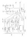
- FIG. 6is a block diagram of an IBR according to one embodiment of the invention.
- FIG. 7is a block diagram of an IBR according to one embodiment of the invention.
- FIG. 8is a block diagram of an IBR antenna array according to one embodiment of the invention.
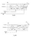
- FIG. 9Ais a block diagram of a Front-end Transmission Unit according to one embodiment of the invention.
- FIG. 9Bis a block diagram of a Front-end Reception Unit according to one embodiment of the invention.
- FIG. 10is a diagram of an exemplary horizontally arranged intelligent backhaul radio antenna array.
- FIG. 11is a diagram of an exemplary vertically arranged intelligent backhaul radio antenna array.
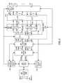
- FIG. 12is a block diagram of a portion of a ZDD enabled IBR according to one embodiment of the invention.
- FIG. 13is a block diagram of a Loop 1 ZDD canceller according to one embodiment of the invention.
- FIG. 14is a block diagram of a Loop 2 ZDD canceller according to one embodiment of the invention.
- FIG. 15is a block diagram of a Loop 3 ZDD canceller according to one embodiment of the invention.
- FIG. 16is a block diagram of a portion of a ZDD enabled IBR including a ZDD Canceller Loop coefficients generator according to one embodiment of the invention.
- FIG. 17is a block diagram of a portion of a ZDD enabled IBR including a Loop 1 (C 1 ) and Loop 3 (C 3 D) cancellers according to one embodiment of the invention.
- FIG. 18is a block diagram of a portion of a ZDD enabled IBR including a Loop 2 (C 2 D) and Loop 3 (C 3 R) cancellers according to one embodiment of the invention.
- FIG. 19is a diagram of the mathematical representation of depicted signals at a ZDD enabled IBR transmitter according to one embodiment of the invention.
- FIG. 20is a diagram of the mathematical representation of depicted signals at a ZDD enabled IBR receiver according to one embodiment of the invention.
- FIG. 21is a diagram of the mathematical representation of depicted signals at a ZDD enabled IBR receive chain input according to one embodiment of the invention.
- FIG. 22is a diagram of a further mathematical representation of depicted signals at a ZDD enabled IBR receive chain input according to one embodiment of the invention.
- FIG. 23is a diagram of a further detailed mathematical representation of depicted signals at a ZDD enabled IBR receive chain input according to one embodiment of the invention.
- FIG. 24is a diagram of the mathematical representation of depicted signals at a ZDD enabled IBR receive chain digital output according to one embodiment of the invention.
- FIG. 5illustrates deployment of intelligent backhaul radios (IBRs) in accordance with an embodiment of the invention.
- the IBRs 500are deployable at street level with obstructions such as trees 504 , hills 508 , buildings 512 , etc. between them.
- the IBRs 500are also deployable in configurations that include point to multipoint (PMP), as shown in FIG. 5 , as well as point to point (PTP).
- PMPpoint to multipoint
- PTPpoint to point
- each IBR 500may communicate with more than one other IBR 500 .
- cellular network infrastructureis more commonly deployed using “microcells” or “picocells.”
- compact base stations (eNodeBs) 516are situated outdoors at street level. When such eNodeBs 516 are unable to connect locally to optical fiber or a copper wireline of sufficient data bandwidth, then a wireless connection to a fiber “point of presence” (POP) requires obstructed LOS capabilities, as described herein.
- POPpoint of presence
- the IBRs 500include an Aggregation End IBR (AE-IBR) and Remote End IBRs (RE-IBRs).
- AE-IBRAggregation End IBR
- RE-IBRsRemote End IBRs
- the eNodeB 516 of the AE-IBRis typically connected locally to the core network via a fiber POP 520 .
- the RE-IBRs and their associated eNodeBs 516are typically not connected to the core network via a wireline connection; instead, the RE-IBRs are wirelessly connected to the core network via the AE-IBR.
- the wireless connection between the IBRsinclude obstructions (i.e., there may be an obstructed LOS connection between the RE-IBRs and the AE-IBR).
- FIGS. 6 and 7illustrate exemplary embodiments of the IBRs 500 shown in FIG. 5 .
- the IBRs 500include interfaces 604 , interface bridge 608 , MAC 612 , modem 624 , channel MUX 628 , RF 632 , which includes Tx 1 . . . TxM 636 and Rx 1 . . . RxN 640 , antenna array 648 (includes multiple antennas 652 ), a Radio Link Controller (RLC) 656 , a Radio Resource Controller (RRC) 660 and a ZDD Canceller 670 .
- the IBRmay optionally include an IBMS agent 700 as shown in FIG. 7 .
- IBRsmay vary from that illustrated in FIGS. 6 and 7 .
- modem 624 of FIGS. 6 and 7produces K transmit symbol streams wherein each of the K transmit symbol streams comprises a sequence of blocks of modulated symbols.
- the K transmit symbol streamswould be destined to a peer receiver at the other IBR in the link.
- the K transmit symbol streamsIn a PMP configuration at the AE-IBR, one or more of the K transmit symbol streams, as designated by the AE-IBR, would be destined to the receiver in each one of the RE-IBRs.
- channel MUX 628 of FIGS. 6 and 7generates M transmit chain input signals, wherein M>K, and each of the M transmit chain input signals may be generated with contribution from one or more (or all) of the K transmit symbol streams.
- each of the M transmit chain input signalsis converted to a transmit RF signal by respective ones of Tx 1 . . . TxM 636 in FIGS. 6 and 7 .
- the M transmit RF signalswould be directed via elements of the antenna array 648 as set by the RRC 660 to a peer receiver at the other IBR in the link.
- one or more of the M transmit RF signalswould be directed via elements of the antenna array 648 as set by the RRC 660 to the receiver in each one of the RE-IBRs. Also, in a PMP configuration at the RE-IBR, the M transmit RF signals would be directed via elements of the antenna array 648 as set by the RRC 660 to the receiver in the AE-IBR.
- M s RF Transmit Reference Signals ( 680 )are passed from the IBR Antenna Array ( 648 ) to the Canceller MUX ( 670 ) for use in cancellation processing and in some embodiments calibration operations.
- M swill be equal to the number of Transmit Antenna Elements Q T in a one to one relationship. Additionally, in some embodiments M s will be equal to the number of RF transmit signals M in a one to one relationship.
- the number of M s RF Transmit Reference Signalsmay be equal to M, in which case the RF switch fabric ( 812 ) within the antenna array ( 648 ) may be utilized to select M s RF transmit reference signals ( 680 ) of the Q T available Transmit Antenna Reference Signals ( 805 ).
- M sis equal to the number of RF Transmit Signals M
- the number of Transmit Antenna Elements ( 652 ) Q Tis greater than the number of RF Transmit Signals M
- the selection of the specific M s RF Transmit Reference Signalswill be made by the RRC ( 660 ), and in correspondence with the selection of the Antenna Elements ( 652 ) utilized for the transmission of the RF Transmit Signals and further may utilize the same selection control signaling or alternative selection control signaling.
- the M s RF Transmit Reference Signals ( 680 )may be obtained directly from the M s RF Transmit Signals within Cancellation MUX 670 , rather than from the Antenna Array 648 .
- the M s RF Transmit Reference Signals ( 680 )may be utilized in analog or digital cancellation processing as will be described in further detail in relation to subsequent figures.
- N receive RF signalsare provided by various elements of the antenna array 648 as set by the RRC 660 and then converted to N receive chain output signals by respective ones of Rx 1 . . . RxN 640 in FIGS. 6 and 7 . Additionally as described in greater detail in U.S. patent application Ser.
- channel MUX 628 of FIGS. 6 and 7generates L receive symbol streams, wherein N>L, and each of the L receive symbol streams may be generated with contribution from one or more (or all) of the N receive chain output signals.
- modem 624 of FIGS. 6 and 7demodulates one or more (or all) of the L receive symbol streams.
- FIG. 8illustrates an exemplary embodiment of an IBR Antenna Array 648 with dedicated transmission and reception antennas.
- FIG. 8illustrates an antenna array having Q R +Q T directive gain antennas 652 (i.e., where the number of antennas is greater than 1).
- the IBR Antenna Array 648includes an IBR RF Switch Fabric 812 , RF interconnections 804 , a set of Front-ends 809 and 810 and the directive gain antennas 652 .
- the RF interconnections 804can be, for example, circuit board traces and/or coaxial cables.
- the RF interconnections 804connect the IBR RF Switch Fabric 812 and the set of Front-end Transmission Units 809 and the set of Front-end Reception Units 810 .
- Each Front-end Transmission Unit 809is associated with an individual directive gain antenna 652 , numbered consecutively from 1 to Q T .
- the IBR RF Switch Fabric 812is further coupled to receive RF Transmit Reference Signals 805 from each Front-end Transmission unit, in specific embodiments, to allow for the selection M s of the Q T RF Transmit Antenna Signals, as previously described, to be provided to the Cancellation Mux 670 as RF Transmit Reference Signals (1 . . . M s ) 680 .
- Each Front-end Reception Unit 810is associated with an individual directive gain antenna 652 , numbered consecutively from 1 to Q R .
- the present embodimentmay be used, for example, with the antenna array embodiments of FIGS. 11 and 12 , or those depicted in U.S. patent application Ser. No. 13/212,036, now U.S. Pat. No. 8,238,318, and Ser. No. 13/536,927 and incorporated herein.
- Exemplary embodiments of the IBR RF Switch Fabric 812are also described in detail in U.S. patent application Ser. No. 13/212,036, now U.S. Pat. No. 8,238,318, and Ser. Nos. 13/536,927 and incorporated herein.
- the IBR RF Switch Fabric 812provides the capability to connect any of the M transmit RF signals to any of the Q T Front-end Transmission Units 809 with associated individual directive gain antenna 652 , or to connect any of the N receive RF signals to any of the Q R Front-end Reception Units 810 with associated individual directive gain antenna 652 .
- the IBR RF switch fabric 812may be bypassed for the selection of the RF Transmit Reference Signals ( 680 ) coupled to the Cancellation MUX ( 670 ), by directly connecting the RF Transmit Reference Signals (1 . . .
- the IBR RF Switch fabric 812may also comprise circuitry to combine signals from two or more Front-end Reception Units or to provide signals to two or more Front-end Transmission Units as described in greater detail in U.S. patent application Ser. No. 13/212,036, now U.S. Pat. No. 8,238,318, and Ser. No. 13/536,927 and incorporated herein.
- each Front-end 809 or 810also includes an “Enable” input 925 , 930 that causes substantially all active circuitry to power-down. Power-down techniques are well known. Power-down is advantageous for IBRs in which not all of the antennas are utilized at all times. It will be appreciated that alternative embodiments of the IBR Antenna Array may not utilize the “Enable” input 925 , 930 or power-down feature.
- Bandpass filter 940receives transmission signal RF-SW-Tx-qt, provides filtering and couples the signal to power amplifier 904 , then to low pass filter 950 .
- FIG. 9Aalso depicts the RF Transmit Reference Signal ( 805 ) which in this exemplary embodiment may be obtained by a line coupler ( 955 ) to the interconnection between low pass filter 950 and directive antenna element 652 wherein the utilization of such RF Transmit Reference Signal ( 805 ) within the ZDD Canceller 670 is described in greater detail herein.
- directive antenna element 652 with gain Gqris a dedicated receive only antenna and coupled to receive filter 970 , which is in turn coupled to LNA 908 .
- the resulting amplified receive signalis coupled to band bass filter 960 , which provides output RF-SW-Rx-qr.
- FIG. 10is a diagram of an exemplary horizontally arranged intelligent backhaul radio antenna array intended for operation in the 5 to 6 GHz band
- FIG. 11is a diagram of an exemplary vertically arranged intelligent backhaul radio antenna array also intended for operation in the 5 to 6 GHz band.
- Analogous versions of the arrangement shown in FIGS. 10 and 11are possible for any bands within the range of at least 500 MHz to 100 GHz as will be appreciated by those of skill in the art of antenna design.
- Q T4 as will be appreciated by those of skill in the art of antenna design.
- each transmit directive antenna element depicted in FIGS. 10 and 11comprise multiple dipole radiators arranged for either dual slant 45 degree polarization ( FIG. 10 ) or dual vertical and horizontal polarization ( FIG. 11 ) with elevation array gain as described in greater detail in U.S. patent application Ser. No. 13/536,927 and incorporated herein.
- each transmit directive antenna elementhas an azimuthal beam width of approximately 100-120 degrees and an elevation beam width of approximately 15 degrees for a gain Gqt of approximately 12 dB.
- each receive directive antenna element depicted in FIGS. 10 and 11comprise multiple patch radiators arranged for either dual slant 45 degree polarization ( FIG. 10 ) or dual vertical and horizontal polarization ( FIG. 11 ) with elevation array gain and azimuthal array gain as described in greater detail in U.S. patent application Ser. No. 13/536,927 and incorporated herein.
- each receive directive antenna elementhas an azimuthal beam width of approximately 40 degrees and an elevation beam width of approximately 15 degrees for a gain Gqr of approximately 16 dB.
- Preliminary measurements of exemplary antenna arrays similar to those depicted in FIG. 10show isolation of approximately 40 to 50 dB between individual transmit directive antenna elements and individual receive directive antenna elements of same polarization with an exemplary circuit board and metallic case behind the radiating elements and a plastic radome in front of the radiating elements.
- Analogous preliminary measurements of exemplary antenna arrays similar to those depicted in FIG. 11show possible isolation improvements of up to 10 to 20 dB for similar directive gain elements relative to FIG. 10 .
- the vertical antenna array arrangement depicted in FIG. 11may be preferable to the horizontal antenna array arrangement depicted in FIG. 10 , providing for additional initial RF isolation.
- FIG. 12is a block diagram of a portion of an IBR according to one embodiment of the invention that illustrates one exemplary embodiment of the ZDD Canceller 670 in greater detail internally and with relationship to other parts of an exemplary IBR.
- the implementation philosophy shown in the current embodimentis based on cancelling the transmit chain signals from the IBR Transmit Antenna Array ( 648 A) that undesirably leak in to the receive chains (comprised of signal flow from IBR Receive Antenna Array ( 648 B) to the receive portion of the IBR Channel Multiplexer ( 628 )).
- ZDD cancellationmay be performed using multiple approaches and at various stages within the IBR receive chains.
- cancellationmay be performed at analog baseband, intermediate frequency (IF), RF and/or digital baseband.
- IFintermediate frequency
- the signal to noise ratio of the Receive Streams (1 . . . L)must be sufficient so as to allow for acceptable demodulation error rate at IBR Modem ( 624 ).
- conventional radiosutilize frequency duplexing or time duplexing to allow for sufficient isolation of the transmitter signals from the signal being received and demodulated.
- isolation of the desired receive signals from transmitted signalsis accomplished utilizing a combination of active cancellation and inherent isolation between the IBR Transmit Antenna Array ( 648 A), and the IBR Receive Antenna Array ( 648 B).
- Embodiments of the Cancellation Loopsgenerally include adaptation based on active measurements of signals, channel estimates, cancellation metrics, or other metrics.
- Loop L 01202
- L 11204
- L 21206
- L 31208
- each individual loopmay be comprised of multiple successive or nested loops of similar or equivalent function, collectively operating as a single loop.
- the Isolation “Loop” L 0 ( 1202 )is mainly just indicative of the finite isolation between any two antennas (Tx to Rx, or Tx to Tx) which is a critical parameter for FDD and even more critical in ZDD.
- Some embodiments of L 0 ( 1202 )will not include adaptive adjustment or utilize active control, but may still be referred to as a Loop for the constancy of the terminology herein.
- Other embodiments of L 0are truly a “loop” to the extent that some feedback mechanism either moves a servo to an isolating structure or a tuning element that affects a different isolation transfer function between any two antennas or sets of antennas of interest for a particular operational mode.
- Such tuning of controlmay further include the optional antenna selection function of Rx Antenna/Channel Switch Matrix within 648 B.
- the operation of the optional Rx Antenna/Channel Switch Matrix within 648 Bis equivalent to that of the receive portions of IBR RF Switch Fabric 812 of FIG. 8 , wherein the selection is performed of N RF Receive Signals (RF-Rx- 1 to RF-Rx-N) of the Q R available RF Receive Antenna Signals (labeled consecutively Y 1 (t) to Y QR (t)) shown in FIG. 12 .
- Such RF Receive Signals ( 678 )are provided to canceller 670 , and more specifically to canceller RF summing nodes (alternatively referred to as RF cancellation combiners) 1210 - 1 to 1210 -N respectively.
- Design of the antenna array for minimal magnitude response by and/or capability of L 0 tuning by feedbackis a key enabler for simplifying the demands of L 1 , L 2 and/or L 3 .
- L 01202
- IBR antenna elements and orientations in a “vertical” array stack as shown in FIG. 11will have better isolation due to the higher elevation gain than azimuthal gain amongst the elements, relative to the horizontal configurations depicted in FIG. 10 .
- the Canceller Loop L 11204 samples the “actual” transmitted RF signal in each Tx chain (RF Transmit Reference Signals 1 to M S ( 680 ) labeled 680 - 1 to 680 -M), and then generates for each Rx chain a modified “cancellation signal C 1 n ” (also referred to in some embodiments as a RF transmit leakage cancellation signal) that when summed (via RF summers 1210 - 1 to 1210 -N) with the Rx chain signals ( 678 ) before input to the downconverters ( 640 ) substantially cancels the Tx signals 1 through M (X 1 (t) to X M (t)) that have leaked into the Rx antennas contributing to each Rx chain “n”.
- RF Transmit Reference Signals 1 to M S ( 680 ) labeled 680 - 1 to 680 -MRF Transmit Reference Signals 1 to M S ( 680 ) labeled 680 - 1 to 680 -M
- L 1 ( 1204 )Exemplary embodiments of L 1 ( 1204 ) are realized by an analog equivalent to a complex FIR “filter” implemented at RF and described in relation to FIG. 13 .
- L 1 ( 1204 )may be implemented by down converting RF Transmit Reference Signals 680 to an intermediate frequency (IF) for FIR processing and then either upconverted back to RF or applied at a cancellation-summing node at IF.
- IFintermediate frequency
- L 1may be targeted at only the largest Tx to Rx coupling paths, and those that are fixed for a specific IBR RF switch fabric ( 812 ) selection.
- Such coupling pathsare expected to involve timescales with variations typically of order 1 ns or less for example in some embodiments.
- Such an approachmay be utilized in other embodiments where longer time delays with mode variation are addressed as well, as a combination of a fixed or slowly adapting L 1 , and a parallel of sequential L 1 cancellers which address the longer delay, lower magnitude, and more highly varying coupling paths.
- Such embodimentsmay include a “primary” loop to address the most significant magnitude response components and once cancelled by the primary loop (typically including L 1 but possibly using part of L 2 or L 3 instead or in addition to L 1 ), this should allow a secondary loop (probably within L 2 or L 3 ) to track shorter variations of much smaller magnitude. Details of exemplary L 1 embodiments are described in further detail in connection with FIG. 13 .
- the Canceller Loop L 2 ( 1206 )also samples the transmitted RF signals (RF Transmit Reference signals 680 ). In some embodiments, it may be preferable not to sample directly as indicated but instead sample by taking a set of interim output signals from within L 1 (there are M ⁇ N such interim cancellation signals) and then applying the additional fine resolution processing of L 2 ( 1206 ).
- L 2is distinctly different from L 1 ( 1204 ) in that L 2 processes Tx signals in the digital baseband domain using FIR digital “filter” techniques which enables L 2 to practically cancel far lower power signals with substantially longer delays than with L 1 ( 1204 ).
- the L 2 cancellation signalcan be upconverted back to RF (“C 2 R n ” as shown) or used as a cancellation signal at digital baseband (“C 2 D n ” as shown and referred to as a baseband transmit leakage cancellation signal in some embodiments).
- summer nodes(alternatively referred to as cancellation combiners) 1212 - n will be respectively utilized to sum the C 2 D n signal with receive chain output signals ( 674 ) from respective receive chains to provide respective baseband cancelled receive signals.
- L 2A major issue with L 2 is the noise and distortion added by the act first of downconverting and digitizing the sampled Tx RF signals, and then further upconverting and leveling if the optional “C 2 R n ” signals are to be generated. Aspects of L 2 embodiments addressing such impairments will be discussed. Note that exemplary embodiments of such processing are depicted and described in further detail in connection with FIG. 14 .
- the Canceller Loop L 3 ( 1208 )is very different from L 1 ( 1204 ) or L 2 ( 1206 ) in that it takes as an input a digital baseband representation of each Tx chain signal Tx 1 (t) to Tx M (t).
- L 3 ( 1208 )all processing of the Tx chain signal can be done using digital FIR “filter” techniques similar to L 2 .
- the input to L 3would be after the digital low pass channel filter 1214 - m .
- the digital filters ( 1214 )can also be replicated in L 3 to generate a better estimate of the actual Tx signal.
- Such replicationprovides for matched channel impacts thus reducing the overall need for the L 3 channel estimation to include compensation for filters 1214 - 1 to 1214 -M. Eliminating the requirement to estimate this filter will allow for a faster or less complex estimation of L 3 cancellation coefficients in some embodiments.
- the effective response of the low pass analog filter ( 1216 - m ) following the DAC, and the BPF ( 1218 - m ) following the upconvertercan also be included in L 3 to improve the cancellation accuracy, efficiency, or convergence speed.
- L 3it is contemplated that other filters may be included in L 3 as well, for instance those in the receiver such as a bandpass filter (not show) following summers 1210 - n , and lowpass filters 1221 - n , and 1222 - n .
- a bandpass filternot show
- lowpass filters 1221 - n , and 1222 - ncertain intermod products in the Tx chain or as created in the Rx front-ends (or in the analog portions of L 1 or L 2 ) can also be modeled within L 3 (or possibly within L 2 ) for cancellation by the L 3 output. Such processing will be further described in connection with embodiments depicted in FIG. 15 .
- L 3( 1208 ) cannot cancel Tx chain noise as L 1 can generally or L 2 can subject to certain limitations.
- the L 3 cancellation signals “C 3 D n ”would be used at digital baseband (referred to as baseband transmit leakage cancellation signals in some embodiments) as shown but optionally these signals can be upconverted as “C 3 R n ” and applied at RF (at summer 1210 - n for instance and wherein C 3 R n comprises an up-converted baseband transmit leakage cancellation signal which acts as a digitally generated RF transmit leakage cancellation signal in some embodiments). It is also possible to generate both “C 3 D n ” and “C 3 R n ” simultaneously and in some embodiments with different emphases on the various undesired signal components to be cancelled.
- the ZDD Canceller Loop Coefficients Generator( 675 ) is notional as shown in FIG. 12 .
- the ZCLCGitself as a “processor” may be within the same resources as the IBR channel multiplexer and/or IBR modem or a standalone processor or a custom chip with one or more of the loops, or some hybrid of some or all of the above in various embodiments.
- Embodiments of the ZCLCGwill also include state machine functionality so as to perform the aforementioned procedures as part of a process, or in reaction to events, or time durations and periods.
- L 0may be modified based upon a change in the selected receive antennas to be utilized within the Receive Antenna Array ( 648 B) and the IBR RF Switch Fabric ( 812 ).
- the loop coefficientsmay be required to be modified by the ZCLCG ( 675 ).
- the timing of such an antenna selection changemay be in coordination with one or more of the RRC ( 660 ), IBR MAC ( 612 ), RLC ( 656 ), and other functional blocks of FIGS. 6 and 7 including IBMS Agent ( 700 ), so as to cause the antenna selection change to be just prior to a known signal transmission period designed and utilized for the training of the ZCLCG.
- Such an approachhas the benefit of potentially minimizing the loss of transmitted information to an intended receiving IBR, and may further include pre-determined waveform properties beneficial to the training and loop coefficient determination.
- Other embodimentsmay perform such a training process on a periodic basis, and/or in response to a measured cancellation performance threshold, a temperature change, or changes in other IBR operating parameters.
- Embodimentsmay also utilize a training process wherein various loops are trained sequentially and utilizing various procedures and algorithms.
- L 1 ( 1204 )may be trained with L 2 ( 1206 ) and L 3 ( 1208 ) effectively turned off, and utilizing a closed loop adaptive algorithm with the goal of minimizing a parameter associated with a transmitted training signal (such as RSSI, or correlated signal power).
- a transmitted training signalsuch as RSSI, or correlated signal power.
- the coefficients of successive loopsmay be progressively determined and set.
- the determination of the coefficientsmay be performed adaptively using a steepest decent class of algorithm, while in other embodiments a close form calculation may be utilized wherein a measurement of the impulse response or frequency response (referred to herein generically as the channel response) is made including an actively cancelling L 1 .
- the channel response measurementwould be made from each transmit chain to each receive chain in some embodiments, and result in M ⁇ N channel measurements (where M is the number of transmit chains, and N is the number of receive chains). Such a channel measurement may then be utilized to calculate the required loop coefficients for L 2 , if present, and L 3 . Such calculations may be performed with the same or separate channel measurements for L 2 and L 3 . In embodiments where separate channel measurements are utilized for L 2 and L 3 coefficient calculation, some embodiments may perform the L 3 channel measurements with L 1 and L 2 cancellation active such that the cancellation performance is include in the resulting L 3 channel measurements.
- the receive gain controlin some specific embodiments, must take into account the remaining transmit signal following the L 1 cancellation process at the summers 1210 - n .
- Some embodimentsmay control the AGC from the ZDD Canceller Loop Coefficients Generator ( 675 ) or from the IBR Modem or IBR Channel Mux instead of from within the Rx chain as shown in FIG. 12 .
- transmit power controlis expected but not shown, and in some embodiments would be under the control (at least partially) of the coefficient generator ( 675 ) so the cancellation performance may aid in the determination of a maximum or desirable transmit power level based upon limitations of the cancellation multiplexer ( 670 ).
- IBR embodiments utilizing ZDDmay be utilized in at least two variants.
- the first variantis “co-channel” ZDD (“CC-ZDD”) wherein the Tx chain channels at least partially overlap (if not completely coincide with) the Rx chain channels.
- CC-ZDDco-channel ZDD
- Embodiments utilizing CC-ZDDare theoretically possible of achieving twice the spectral efficiency for a single link at the physical layer, relative to systems not utilizing ZDD approaches.
- ARQautomatic retransmission
- additional efficienciesare possible.
- the delay reduction relative the TDD based systemsis significant.
- This CC-ZDD modeis ideal for licensed band operation where interference is well controlled and spectral efficiency most highly valued.
- the second ZDD variantcan be called “single band” or “co-band” ZDD (CB-ZDD) wherein both the Tx chain channels and the Rx chain channels are within a single band (using a single band pass filter) utilized during both transmission and reception, but the channels do not overlap.
- CB-ZDDco-band ZDD
- Such an arrangementresults in minimal spectral efficiency improvement (though FDD is typically better than TDD) but is still highly desirable at least as a fallback mode for unlicensed band operation.
- One advantage of CB-ZDD in unlicensed bandsresults from the interference seen at the receiver of one IBR, being dramatically different (and frequency dependent) compared to its peer device such that operating in a similar frequency range allows for a more optimized channel frequency choice under significant interference conditions.
- CB-ZDDco-band ZDD
- CB-ZDDco-band ZDD
- the analog and/or digital baseband low pass filtersas well as the FFTs in the IBR channel multiplexer
- CB-ZDDhas the additional complication that the “easily” detectable Tx signal that drives the ZCLCG process is not at the right channel frequency to ensure noise cancellation in the Rx chain under normal operating conditions.
- Tx noise cancellationmay be utilized mitigating much of this disadvantage, such as adapting the loops based upon receiver performance metrics such as signal to noise ratio (SNR), bit error rate (BER), frame error rate (FER) or metrics associated with the forward error correction (FEC).
- SNRsignal to noise ratio
- BERbit error rate
- FERframe error rate
- FECforward error correction
- CC-ZDD(and potentially CB-ZDD) has specific applicability in use in an ZDD Aggregation End IBR (AE-IBR) when operating in a point to multi-point (PMP) mode in communication with multiple non-ZDD Remote End IBRs (RE-IBRs) operating each in a TDD mode.
- AE-IBRZDD Aggregation End IBR
- RE-IBRsRemote End IBRs
- Such a configurationallows for the ZDD enabled AE-IBR to be transmitting to one or more RE-IBRs, whilst receiving from one or more other RE-IBRs.
- no ZDD cancellationis required at the RE-IBRs, but a doubling of the overall network efficiency is realized relative to AE-IBRs not utilizing ZDD.
- a time multiplexing of one or more of the AE-RE links and RE-AE linksmust be arranged and scheduled such that the RE-IBRs are time multiplexed with their transmission and reception periods, and offset relative to other RE-IBRs, at least to the extent that TDD operation is achievable at each RE-IBR individually, not considering other multipoint multiplexing approaches such as frequency multiplexing (such as Orthogonal Frequency Division Multiple Access (OFDMA), Single Carrier Frequency Division Multiplexing (SC-FDM), and the like).
- OFDMAOrthogonal Frequency Division Multiple Access
- SC-FDMSingle Carrier Frequency Division Multiplexing
- ZDD repeater embodimentsmay utilize ZDD approaches to allow for reception and transmission of signal simultaneously allowing for higher efficiency relative to TDD based repeating approaches, or more spectral efficiency relative to FDD based repeating approaches.
- ZDD repeater embodimentsmay perform the repeating function in a number of approaches including: at an RF and un-demodulated level, a modulation symbol by symbol level, a stream level, an FEC Block Level, a MAC Frame Level, or potentially higher levels.
- beam forming techniquesmay be utilized to allow for a spatially rich propagation environment allowing for an increased performance network.
- Embodiments of a Loop 1 (L 1 ) ( 1204 ) canceller of cancellation multiplexer ( 670 )are depicted in FIG. 13 .
- An exemplary Loop L 1 embodimentsamples the “actual” transmitted RF signal in each Tx chain ( 1302 - m ), and then generates for each Rx chain a modified “cancellation signal C 1 n ” ( 1318 - n ) that when applied to summing node ( 1210 - n ) with the Rx chain signal ( 678 - n ) before input to the downconverter ( 1220 - n ) substantially cancels the Tx signals 1 through M that have leaked into the Rx antennas contributing to Rx chain “n”.
- Some embodiments of L 1are realized by an analog equivalent to a complex FIR “filter” implemented at RF.
- Alternative embodiments of L 1provide for signal to be down converted to an IF for FIR processing and then either up converted back to RF or applied at IF.
- the transfer function G Sm ( 1306 - m )is intended to indicate a “zero-th” order match between the magnitude and delay from X m (t) to an average Rx chain at the first summer and a known frequency response.
- the delaymight be realized in a cable of preset length that approximates the delays in the Tx-Rx path.
- the transfer functionmight be strongly influenced by one or more band pass filters in each Rx chain, or other filters in either the transmit or receive paths which are “in the loop”, and so it may be advantageous to place an identical band pass filter (or other such “in the loop” filters) within each G Sm ( 1306 - m ). This has the additional benefit of keeping out of band Tx spurs from being injected into the Rx chains.
- the transfer functionalso includes the effect of the coupling to X m (t), by a line coupler near the Tx antenna feed point in some embodiments. It is desirable to sample a signal highly correlated to the actual X m (t) transmission and to have sufficient signal such that the sampled noise floor is far above the equivalent input noise of L 1 .
- a delay line ( 1310 )is of length D 1 * ⁇ t 1 and for each delay tap, weights W 1 m,n,d ( 1311 ) are complex with separate I and Q components, while in other embodiments such weights may be in amplitude only.
- the weights ( 1311 )are typically sent from the ZCLCG ( 675 ) as finite bit words (i.e. 8, 10 or 12 bits per I or Q component).
- the weights ( 1311 )come from an analog feedback loop.
- L 1is “matched” to reflections including transmit to receive propagation time delays up to a maximum time delay (such a maximum time delay sufficient to address all reflections above a specific magnitude threshold) then there may be non-uniform time steps that result in a better cancellation by design.
- the typical delay within G Smwill be of order 1 ns, and the delay line length will be of similar order or possibly less.
- 3 “taps”may be impractical for a 2 ⁇ 4 system, but when implemented in a custom RFIC it may be practical to have on the order of 5-10 delay steps, while other embodiments may have yet more taps.
- each complex multiplier ( 1312 )can be constructed, for example only, from a pair of four-quadrant multipliers wherein one multiplier is driven by an “I” set of weights and the other by a “Q” set of weights (collectively a complex weight 1310 in the current embodiment), and further wherein either the RF input signal to the second multiplier is shifted 90 degrees relative to the first or the outputs of the respective multipliers are summed (at summer 1314 in some embodiments) in quadrature instead of linearly.
- a delay line utilizing complex samples and weightsmay be implemented with a single delay line and linear summation, wherein each I and Q sample in the delay line are sampled from different taps spaced at 1/(fo*4) in time, where fo is the center frequency of operation of the band, and if the delay between each “pair” of taps is equated to 1/BW, then BW is the frequency bandwidth of the cancellation bandwidth.
- each pair of tapscomprise in phase and quadrature phase (or real and imaginary) samples at a specific “tap”.
- FIG. 14a block diagram of a Loop 2 ZDD canceller according to one embodiment of the invention is depicted.
- the Canceller Loop L 2( 1206 ) also samples the transmitted RF signals though in some implementations it may be preferable not to sample directly as indicated but instead by taking a set of interim output signals from within L 1 ( 1204 ) as there are M ⁇ N such interim cancellation signals in some embodiments and then applying the additional fine resolution processing of L 2 .
- the “FIR” filter structures of L 1may be incorporated into L 2 ( 1206 ).
- Such an arrangementmay be utilized in embodiments not having a L 1 ( 1204 ), but utilizing advantages of combining transversal filtering at RF of each of the transmitters individually (utilizing L 1 weights) into all of the sampling receivers of L 2 .
- Such an arrangementallows for advantages in capturing and utilizing transmitter and receiver noise (especially phase noise) in specific combinations.
- passive components and micro-strip linesutilize a printed circuit board or other substrate.
- Such arrangementsallow for a “spatial multiplexing” by the RF filter structures of all transmitter signals onto each of the sampling receivers.
- FIG. 1408Further embodiments allow for use of such FIR structures, or delay line structures to spatial multiplex RF Transmit Reference Signals ( 680 - m ) with receive chain signals ( 678 - n ) by utilizing either the signal receive chains ( 1225 - n ) and/or the sampling receive chains ( 1406 - m ).
- receive chain signals 678 - n and RF Transmit Reference Signals ( 680 - m )would be coupled to more than one of the utilized signal receiver chains ( 1225 - n ) and sampling receive chains ( 1406 - m ) to multiplex signals.
- Further additional processing to de-multiplex the signalswill be performed to de-multiplex the receive chain and sampling receive chain signals prior to applications to the L 2 FIR filters ( 1408 ).
- Other embodimentsmay utilize arrangements of signal receive chains ( 1225 - n ) alone or sampling receive chains (alternatively referred to as transmit RF reference receive chains in some embodiments) ( 1406 - m ) alone.
- Baseband processing equivalent to MIMO receiver processingmay be utilized to separate the individual combinations of transmitter to sampling receiver signals.
- specific arrangements of shared VCOsare utilized among receivers and sampling receivers and between transmitters and in some cases C 3 R up converter chains, the VCO phase noise impact may be greatly mitigated or even eliminated.
- a single shared VCOis utilized for all up converters and down converters for the transmitters, receivers, sampling receivers, and any C 3 R up converters.
- Such an arrangementdoes not require the RF “spatial multiplexing” discussed above in order to address phase noise concerns as the transmitter phase noise when received using a C 2 D sampling receiver ( 1406 , alternatively referred to as transmit RF reference receive chains in some embodiments) will have a common noise as the transmitter signal when received on the signal receivers ( 1225 - 1 through 1225 -N).
- VCOsmay share VCOs between all up converters (that generate C 3 R n ) and transmit chains ( 636 ), and between all down converters within C 2 D sampling receivers ( 1406 - m of 1404 - 1 through 1404 -M, and alternatively referred to as transmit RF reference receive chains in some embodiments) and signal receivers ( 1225 - 1 through 1225 -N). Further embodiments may utilize common VCOs between pairs of down converters in a respective sampling receiver and signal receiver, or similarly utilize common VCOs for pairs of up converters for a respective signal transmitters and C 3 R up converter chain.
- L 2processes Tx signals in the digital baseband domain using FIR “filter” ( 1408 ) techniques that enable L 2 to cancel far lower magnitude signals with substantially longer delays than with L 1 .
- the L 2 cancellation signalcan be upconverted back to RF (“C 2 R n ” not shown in FIG. 14 ) or used as a cancellation signal at digital baseband (“C 2 Dn” as shown).
- C 2 R nRF
- C 2 Dndigital baseband
- the inputs from X m (t)can be a line coupled input as described for L 1 , or can be from the same G Sm ( 1306 - m ) (or a parallel G Sm for L 2 only) as described for L 1 .
- the number of transmitters Mmay be different from the number of receivers N.
- sets of weights ( 1311 )may be chosen so as to allow for a “spatial” multiplexing between the transmitter signals and the separation of each of the transmitter signal components from one another including associated transmitter noise and specific sampling receiver ( 1406 - m ) noise as discussed above.
- phase noise of both the Tx chains and the Rx chainsare particularly problematic for the operation of L 2 D processing.
- each signal receiver1225 - n
- an L 2 D sampling receiver1406 - m
- the demultiplexingmay be performed utilizing specific weights and processing within the FIR filters of FIG. 14 ( 1408 for example).
- the so called filter weights for each FIR filter 1408may be comprised of the convolution of weights for coefficients to separate specific transmitter and receiver components, and to compensate for Tx to Rx frequency responses to allow for cancellation.
- processingmay be performed in the frequency domain rather that in the time domain or in additional processing not depicted in FIG. 14 .
- the preceding embodimentindicates a conventional complex FIR filter structure for CFIR 2 ( 1408 ). It may be desirable when L 2 is being used to cancel significant variations in overall delay of the Tx to Rx chain coupling paths to, in some embodiments, have a complex CFIR 2 with a smaller time delay for certain of the taps and longer for the remainder, or to have parallel complex FIR structures with different time delay steps and then sum them together.
- each sampling receiver chain( 1406 - m ) may be realized in practice using conventional components or incorporated in an RFIC.
- Each CFIR 2 m,n ( 1408 ) and digital domain summation ( 1410 - n )can be constructed using conventional digital circuits in either an ASIC or FPGA, or realized in software on a DSP.
- the Canceller Loop L 3( 1208 ) is very different from L 1 ( 1204 ) or L 2 ( 1206 ) in that it takes as an input a digital baseband representation of each Tx chain signal Tx 1 (t) to Tx M (t).
- L 3 ( 1208 )all processing of the Tx chain signal can be done using digital FIR “filter” techniques similar to L 2 .
- the input to L 3would be after the digital low pass channel filter 1214 - m .
- the digital filters ( 1214 )can also be replicated in L 3 to generate a better estimate of the actual Tx signal.
- Such replicationprovides for matched channel impacts thus reducing the overall need for the L 3 channel estimation to include compensation for filters 1214 - 1 to 1214 -M. Eliminating the requirement to estimate this filter will allow of a faster or less complex estimation of L 3 cancellation coefficients in some embodiments.
- the effective response of the low pass analog filter ( 1216 - m ) following the DAC, and the BPF ( 1218 - m ) following the upconvertercan also be included in L 3 to improve the cancellation accuracy, efficiency, or convergence speed.
- L 3it is contemplated that other filters may be included in L 3 as well, for instance those in the receiver such as a bandpass filter (not show) following summers (alternatively referred to as cancellation combiners) 1210 - n , and lowpass filters 1221 - n , and 1222 - n .
- a bandpass filternot show
- cancellation combinersalternatively referred to as cancellation combiners
- lowpass filters1221 - n , and 1222 - n .
- certain intermod products in the Tx chain or as created in the Rx front-endscan also be modeled within L 3 (or possibly within L 2 ) for cancellation by the L 3 output.
- L 3( 1208 ) cannot cancel Tx chain noise as L 1 can generally or L 2 can subject to certain limitations. Techniques to mitigate such noise impacts may be addressed associated with L 1 or L 2 as discussed. One such approach combining C 2 D n and C 3 R n will be discussed associated with FIG. 18 . In particular, an approach for capturing correlated C 3 R n noise components by a C 2 D n receiver for later cancellation has been discussed and is disclosed in greater detail.
- the L 3 cancellation signals “C 3 D n ”, where n is from 1 to N,would be used at digital baseband as shown but optionally these signals can be upconverted as “C 3 R n ” and applied at RF. It is also possible to generate both “C 3 D n ” and “C 3 R n ” simultaneously and possibly with different emphases on the various undesired signal components to be cancelled, however this would require additional FIR circuitry (not shown) to account for the different magnitude, phase and delay between C 3 R n and C 3 D n even for the “same” cancellation signal effect.
- weightsare typically sent from the ZCLCG ( 675 ) as finite bit words (i.e. 12, 16, or more bits per I or Q component).
- FIG. 15additionally illustrates an intermod generator IMGTx m ( 1510 ), where m may be from 1 to M, which may be used to estimate IM signal components caused by the Tx PA in chain m. It is expected that the weights used for any CFIR 3 following the IMGTx m would be the same as for the other CFIR 3 under the reasonable theory that the IM components out of the Tx m would experience the same propagation paths to each Rx n as the rest of X m (t). Each IMGTx m ( 1510 ) may also take from the ZCLCG ( 675 ) certain weights (not shown) that optimize parameters within the intermod model based on observed or calculated results.
- IMGTx m1510
- mmay be from 1 to M, which may be used to estimate IM signal components caused by the Tx PA in chain m. It is expected that the weights used for any CFIR 3 following the IMGTx m would be the same as for the other CFIR 3 under the reasonable theory
- intermods of potential interestinclude those created in the RF LNA of each receive chain n and those created within the other cancellers (such as L 1 per the indication above).
- Each RF LNAmay generate intermods of all M Tx signals each of which may be uniquely transferred to each Rx.
- cancellation of such intermodsrequires at least a bank of M CFIR 3 Rx m ( 1502 - m ) for each Tx m , each comprising N CFIRs of length D 3 RF taps and weights (not shown).
- intermodsare then modeled based on M inputs at each respective IMGRx n ( 1504 - n ) wherein certain weights (not shown) may be passed to optimize the model in view of observed results.
- thesecan be estimated for each X m (t) by applying Tx m (t) to IMGC 1 m ( 1512 ) as shown above and then applying the result to a bank of N CFIR 2 C 1 - m each of D 3 C 1 taps in length with weights (not shown) supplied by the ZCLCG ( 675 ).
- the various operational and design parametersare chosen such that none of the intermod cancellers depicted above are necessary. However, this will not always be the case particularly for high transmit powers associated with longer range operation.
- All of the CFIR, IMG and summation circuits ( 1514 , 1520 , etc) depicted in FIG. 15can be realized by conventional digital circuit techniques in an ASIC or FPGA, or alternatively by software in a DSP.
- the optional C 3 R upconverter chains ( 1506 - 1 to 1506 -N) depictedcan be implemented in an RFIC or in commercially available RF transmitter components.
- FIG. 16is a block diagram of a portion of a ZDD enabled IBR including a ZDD Canceller Loop Coefficients Generator (ZCLCG) according to one embodiment of the invention.
- ZCLCGZDD Canceller Loop Coefficients Generator
- a basic process of subsequent cancellations based on an RRC setting (first order) and RLC setting (second order)is employed.
- a start-up techniqueis for both ends of an IBR link in a given channel to start-up initially in a TDD service mode that allows the IBRs to exchange key RRC data and establish common frame sync.
- L 0 “coefficients”are chosen first, typically from a non-volatile memory set by design or factory calibration (and possibly, or alternatively, within the Coefficients Memory ( 1606 )).
- L 0 coefficients or settingshave multiple valid values for given RRC parameters, such values can be tested by inserting Tx-m chain preambles (serially or in parallel as described below for L 1 ), and then applying FFT (or even just an RSSI, not shown, but available from the sampling receiver chain ( 1225 - n ) in one embodiment, or elsewhere in further embodiments) to each (or all) Rx n to measure the effects on undesired Tx m signal leakage into each Rx. This can be iterated until a minimum leakage value is determined.
- the L 0 settingsmay be balanced with an identified desirable IBR receive signal.
- such a balancecomprises determining settings achieving a target threshold receive signal strength, or SNR, or other metric for a desired receive signal, and a target L 0 isolation level.
- SNRreceive signal strength
- L 0 isolation levela target threshold receive signal strength, or other metric for a desired receive signal
- f DS (W 0 (i))is a function of the desired receive signal, where W 0 (i) are L 0 coefficients sets as a function of i, and in one embodiment include the RRC antenna selection settings of the IBR antenna array ( 648 ). Note that i is an index which ranges in value from 1 to the total number of possible W 0 (i) setting combinations.
- f ISO (W 0 (i))is a function of the isolation between each transmit chain and each receive chain, where W 0 (i) are L 0 coefficients sets as a function of i, and in one embodiment include the RRC antenna selection settings of the IBR antenna array ( 648 ).
- the functions f DS , and f ISO in some embodimentare linear functions, while in other embodiment are nonlinear functions, or a combination.
- the functionsare a comparison to one or more thresholds, or fuzzy logic processing.
- the functionstake the form of a global optimization function determining the maximum link throughput between two or more IBRs. Embodiments of such a function balance the target IBR received throughput and reliability and the current IBR's receive throughput and reliability as function of W 0 (i) settings. Examples of some of such embodied optimization algorithms associated with the L 0 setting process, or associated with the other loop settings may be found in Systems Engineering in Wireless Communications , by Koivo and Elmusrati (ISBN 0470021780).
- an initial guess for the L 1 coefficientswould be read from a non-volatile memory set by design or factory calibration (and possibly within the Coefficients Memory ( 1606 )).
- An iterative processwould commence wherein Tx m preambles (either serially or in parallel initially) are inserted into each Tx m and the effect on each IQ magnitude bin for each Rx n is considered to modify the coefficients to minimize observed Tx m in each Rx n .
- Coefficients Generator Processor ( 1610 ) and/or Coefficients Calculator ( 1608 )can use, such as iteration by steepest descents (or alternatives such as those disclosed within Koivo and Elmusrati), to determine the coefficients in view of the previous values of W 1 m,n,d and previous IQ magnitude bins given a new observed set of IQ magnitude bins for a new tested set of W 1 m,n,d .
- Such processingmay be performed as time domain based algorithm, or utilizing frequency domain based processing, or as a combination of both domains.
- the Tx m preamblesmay be inserted in parallel to optimize the W 1 m,n,d in view of Tx m1 to Tx m2 leakage that passes through L 1 and creates an additional leakage path independent of L 0 into each Rx n from each Tx m .
- the Critical Timing Unit ( 1616 )schedules the preamble insertions and FFT sampling in view of the Tx Symbol Clock (for precise preamble symbol insertion) and the Tx Frame Sync (so that, for example, Tx m preambles are sent when other IBRs in receive antenna view of the instant IBR in the same Rx channel have their Tx signals substantially inhibited in power).
- Such timingmay also be coordinated via the IBMS Agent ( 700 ) in cooperation with other IBRs or an IBMS Server as described in co-pending application U.S. Ser. No. 13/271,057 by a common inventor and assignee.
- L 1is not present but L 2 is
- the above processwould be performed in a similar manner for L 2 in some embodiments.
- the optimization of such W 2 m,n,dwould in some embodiments, be performed similar to the process described below for L 3 in some embodiments.
- the L 2 coefficientsmay be calculated by closed form approaches rather than using iterative algorithms. Such algorithms may include so called MMSE and LMS based approaches in some embodiments, which will be described in more detail.
- reflection cancellationsare made using either L 2 or L 3 (for example, using L 3 , as in L 3 D only in certain embodiments as depicted associated with FIG. 17 , or parallel L 3 R and L 3 D loops in other embodiments).
- L 3 coefficientswould also be an iterative process to determine W 3 m,n,d coefficients but it is unlikely that a meaningful initial guess would exist from design or factory calibration relative to an actual deployment location.
- the number of preamble/FFT cycles to convergemay be substantial.
- the number of calculations required for each preamble/FFT cycle in view of the many potential CFIR taps in L 2 or L 3may be substantial.
- Tx power and certain component parameterscauses substantial IM signals that are insufficiently cancelled by L 1 and/or L 2
- a final process to compute CFIR 3 tap weights and IM model parametersis required.
- thiscould be done by having the Critical Timing Unit ( 1616 ) also control a Tx Power Control circuit ( 1602 ) (for example, shifting away 1 or 2 bits in each Tx chain for symbol timing level 6 or 12 dB power control steps) that should allow FFT sampling to pick up the effects of IM processes due to the non-linear effect of such leakage signals within each Rx-n as a function of Tx power level.
- One exemplary procedure for this update processwould be to periodically, such as once every L 3 U frames (where L 3 U may be 1 to 10 depending on the environment), have the Critical Timing Unit send one or more Tx m chain preambles, while the other IBRs in view of the Rx antennas at the Rx channel frequency substantially inhibit their Tx power, and effectively repeat the W 3 m,n,d coefficient calculation process if the IQ magnitude bins have increased beyond some threshold from the previous test stored in memory.
- every L 1 U frames(where L 1 U may be 100-1000 depending on the environment), the W 1 m,n,d coefficients may be re-tested with C 2 and/or C 3 inhibited to recalculate W 1 if a change beyond a threshold has occurred.
- this W 1 testmay be scheduled only if the L 3 (and/or L 2 ) update process fails to keep the residual Tx signals in one or more Rx n below a particular threshold value.
- the channel dynamicsmay be far slower or faster changing than in others. Thus, it may also make sense to have L 1 U , L 2 U , and/or L 3 U into parameters that are adaptive to the estimated channel dynamics.
- a closed form LMS or MMSE calculationmay be made to determine L 2 or L 3 weights (or other weights for that matter).
- a least squares closed form based approachmay be utilized in a C 2 D (or analogously for calculating L 3 weights in a C 3 D) cancellation wherein the sampled RF Transmit Reference Signals (X S1 to X SM ) corresponding to signals associated with 680 - 1 through 680 -M, using sampling receivers ( 1406 - m ), are compared with the receive chain output signals ( 674 ) prior to summer (or alternatively referred to as combiners) 1212 - n (or at 1212 - n with C 2 D and/or C 3 D temporarily inhibited) to calculate the coefficients W 2 m,n,d , utilizing a closed form calculation.
- Some embodimentswill utilize a least squares calculation, or MMSE calculation which when performed in the time domain requires a large matrix inversion. Alternatively such calculations may be performed in the frequency domain to achieve a closed form solution. For example in one embodiment, the following process is followed for each receiver chain n, where n varies from 1 through N:
- a vector of sampled receive data(Zs n ) is assembled from S R complex valued time domain samples of Z Sn (t) at the output of receiver chain 1225 - n , taken from the input ( 674 - n ) of cancellation combiner (alternatively referred to as cancellation summers) 1212 - n .
- Zs nis arranged to have the dimensions S R by 1, and that S R ⁇ D 2 , where D 2 is the number of taps in each CFIR 2 ( 1408 ).
- the Fourier transform of Zs nis taken to provide FZs n (also having dimensions S R by 1).
- Such a Fourier transformmay be realized in any one of known conventional approaches, including utilizing FFT processing block 1614 , with additional coupling to signals at reference points 674 to obtain time domain samples of Zs n (not shown in FIG. 16 ) or from Rx n directly with C 2 D and/or C 3 D temporarily inhibited.
- each vector (Xs m ) of sampled RF Transmit Reference Signals datais assembled from S R complex valued time domain samples of X m (t) at the output ( 1409 - m ) of the sampling receiver chain ( 1406 - m ) of block 1404 - m , for each reference signal.
- each vector Xs mis arranged to have the dimensions S R by 1, and that S R ⁇ D 2 , where D 2 is the number of taps in each CFIR 2 ( 1408 ).
- the Fourier transform of Xs mis taken to provide FXs m (also having dimensions SR by 1).
- Such a Fourier transformmay be realized in any one of known conventional approaches, including utilizing FFT processing block 1614 , with additional coupling the signals at reference points 1409 - m of each sampling receivers 1406 - 1 through 1406 -M to obtain time domain samples of Xs m (not shown in FIG. 16 ).
- the M vectors of FXs mmay further be arranged to form a matrix FXs of dimension S R by M, where each column contains a single vector FXs m .
- FW 2 n EST ( b )[ FXs ( b ) H FXs ( b )] ⁇ 1 FXs ( b ) H FZs n ( b ) (Eq. 14-1) where b indexes frequency bins 1 through S R , and where the “H” superscript refers to the Hermitian (conjugate) transpose of a matrix, and the superscript “ ⁇ 1” refers to a matrix inversion and, where, FZs n (b) is a complex scalar and FXs(b) is comprised of a 1 by M vector, and FW 2 n EST (b) is an M by 1 vector, where each element comprises the b th complex frequency domain bin value of the frequency domain estimation of the filter taps associated with CFIR 2 m,n .
- the newly determined (M by S R ) matrix FW 2 n ESTmay be combined utilizing a weighted averaging, or other filtering approaches, on an bin by bin basis with previously utilized or estimated versions of matrix FW 2 n EST resulting in matrix FW 2 n Filt .
- the frequency domain based filteringmay be performed in a later time domain step, and vector FW 2 n EST may be substituted for the subsequent step referencing the matrix FW 2 n Filt .
- W 2 n ESTwhich comprises estimates of the time domain FIR filter weights as a vector of dimension M by S R , where S R is ⁇ D 2 (the number of filter taps per FIR 2 ( 1408 )).
- W 2 nis calculated by performing a truncation of W 2 n EST from M by SR to a M by D 2 , where for each receive chain the most significant magnitude coefficients will be contained in the first D 2 values of the M rows of W 2 n EST .
- a time domain sample-by-sample averaging, weighted averaging (FIR), recursive (IIR) filteringmay be performed with previous calculated versions of W 2 n EST or W 2 n . Note that each row W 2 n corresponds to the weights, W 2 m,n,1 to W 2 m,n,D2 for the corresponding CFIR m,n ( 1408 ).
- FIG. 17a block diagram of a portion of a ZDD enabled IBR including Loop 1 (C 1 ) ( 1204 ) and Loop 3 (C 3 D) ( 1208 ) cancellers is depicted according to one embodiment of the invention.
- all labeled signals in FIG. 17are complex, represented by either I and Q or magnitude and phase.
- the isolation in L 0 ( 1202 ) and the cancellation capability of L 1are sufficient that only L 3 with digital baseband outputs is required for CC-ZDD operation.
- the L 3 ( 1208 )in a preferred embodiment does not need IM cancellation circuits.
- L 0 ( 1202 )includes the effects of each transmit antenna signal X m (t) on every receive antenna signal Y q (t), as well as on every other X m (t). Note also that every antenna, X m (t) and Y q (t), may be subject to receiving unwanted interference I(t) as well as the desired signal from another IBR and various undesired leakage signals from the instant IBR.
- each Rx n (t)does not have a level of any X m (t) (or other undesired signal introduced by the instant IBR and not the outside world radiating into each receive antenna) that causes appreciable (typically more than 1 dB) desensitization at the demodulator relative to an equivalent receiver where each X m (t) at the instant IBR has zero power.
- FIG. 18a block diagram depicting of a portion of a ZDD enabled IBR including a Loop 2 (C 2 D) and Loop 3 (C 3 R) cancellers according to one embodiment of the invention.
- the noise from the cancellation transmitters 1506 - 1 to 1506 -Nmay be compensated for by sharing L 0 frequency sources (VCOs) between the signal transmitters and the C 3 R transmitters such that the phase noise is common to all up converted signals allowing for the cancellation of the transmitted phase noise at summers (alternatively referred to as cancellation combiners) 1210 - n .
- VCOsL 0 frequency sources
- utilizing a shared VCO between the C 2 D sampling receivers ( 1406 - m ) and signal receive chains ( 1225 - n )allows for a common phase noise component between all receivers allowing for the cancellation of phase noise at baseband in C 2 D or related digital cancellation.
- the individual phase noise componentsmay be recovered for use in further cancellation processing using noise components individually (the shared transmit phase noise, and the shared receive phase noise).
- transmitter leakage signals from IBR transmit array ( 648 A)may be canceled at 1210 - n utilizing C 3 R processing allowing for a cancellation of the leakage signals such that the ADCs within the signal receive chains ( 1225 - n ) are not saturated.
- Such embodiments sharing a common VCO among all up converters and a common VCO among all down converters down convertersallows for the cancellation of the transmitter leakage signal and the transmitter phase noise at 1210 - n .
- transmitter noisemay not be cancelled when the transmitter leakage signal is cancelled (when the C 3 R up converter VCOs are not shared with the transmit chain VCOs) and remain in the signal receive chains ( 1225 - n ), and the remaining phase noise may be cancelled in C 2 D processing and associated processing utilizing references for the up converter or down converter phase noises.
- VCOsare shared only among pairs of transmitters and pairs of receivers.
- the phase noise combinationsmay be recovered and compensated for in further cancellation processing at base band during C 2 D or C 3 R processing.
- FIG. 19is a diagram of the mathematical representation of depicted signals at a ZDD enabled IBR transmitter according to one embodiment of the invention.
- X m (t)is linearly related to Tx m (t) except for the additive IM and noise terms.
- the IM termsmay be modeled from Tx m (t) depending on the mechanism that causes them.
- the noiseis uncorrelated from Tx m (t) and thus L 3 cannot cancel the Tx noise in the receiver in embodiments of FIG. 17 .
- the sampled Tx m (t) signals utilized by L 1are predominantly G Sm ⁇ X m (t). However, they may also include unwanted leakage of other transmit signals on a theoretically infinite number of propagation paths as shown in Eqs. 19-3 and 19-4 of FIG. 19 . There may also be uncoordinated interference present at each Tx antenna but generally if this were significant it would probably already cause significant interference at one or more receive antennas in specific embodiments. There is also at least thermal noise present at the input to L 1 .
- N Sm (t)may be far below the transmitter noise [G Sm ⁇ N Txm (t)] in magnitude, the effect of N Sm (t) combined with the transfer function within L 1 and its noise figure will be injected at Z n (t) into each receiver chain, while the transmitter noise is theoretically cancelled out (and there is no practical way to cancel N Sm (t)).
- FIG. 20is a diagram of the mathematical representation of depicted signals at a ZDD enabled IBR receiver according to one embodiment of the invention.
- each Y q (t), of Eq. 20-1receives a desired signal from its peer IBR (Y Rxq (t)) as well as both exemplary transmit signals X m (t), each of which reaches Y q (t) by a theoretically infinite number of delay paths and complex transfer functions, plus the input noise and interference at each antenna.
- the signalis composed of all 8 Y q (t) signals multiplied by respective complex transfer functions and subject to a small delay plus the equivalent input noise for the downconverter chain and the L 1 cancellation signal, as well as any intermod products generated in the circuits from antenna q to downconverter n (especially in view of Tx leakage from X m that may be much larger than Y Rxq ).
- the effect of the switch matrix and the LNA power down when a particular receive antenna is not selectedtypically results in the selected q n mapping having a magnitude of G Rxq,n that greatly exceeds that of all unselected mappings.
- the L 1 cancellation signalcan be described as a summation across the two sampled transmit signals Xs m (which each comprise X 1 and X 2 due to finite Tx to Tx antenna isolation) weighted by complex transfer functions W 1 m,n,d at delays of approximately “d* ⁇ t 1 ” (but not necessarily uniform delay steps in some embodiments) and G 1 m,d (in some embodiments these might all be unity but in practice with RF delay lines these will vary somewhat in other embodiments), plus undesired intermodulation products created within L 1 as indicated.
- FIG. 21is a diagram of the mathematical representation of depicted signals at a ZDD enabled IBR receive chain input according to one embodiment of the invention.
- L 1 cancellation component(or “L 1 output signal”) which in an ideal world would be exactly equal to, but opposite in sign to, the undesired Tx leakage component. In reality, this is not possible, but if L 1 sufficiently cancels certain key sub-components of the Tx leakage, then L 2 or L 3 may be able to sufficiently cancel the rest for CC-ZDD. In the case of CB-ZDD, then L 1 needs to cancel only the Tx leakage noise (and IM signals if present) in the Rx channel to be acceptably low relative to the noise plus interference component.
- FIG. 22is a diagram of a further mathematical representation of depicted signals at a ZDD enabled IBR receive chain input according to one embodiment of the invention. Substituting previous representations of X m (t) (Eq. 19-1 and 19-2) and C 1 n (t) (Eq. 20-3) creates a more detailed description of Z n (t) (Eq. 22-00).
- Equation components (22-01) and (22-02)are equivalent equation segments (21-01) and (21-02) of FIG. 21 , respectively.
- Equation Segment (22-03)is the first of three subcomponents of the “undesired Tx leakage” component from the previous slide. This particular subcomponent is representable in terms linearly related to the original Tx chain baseband digital signal Tx m (t).
- Equation Segment (22-04)is the second of three subcomponents of the “undesired Tx leakage” component from the previous slide. This particular subcomponent comprises the Tx chain output noise.
- Equation Segment (22-05)is the third of three subcomponents of the “undesired Tx leakage” component from the previous slide. This particular subcomponent comprises the Tx chain output intermods.
- Equation Segment (22-06)is the first of three subcomponents of the “L 1 output signal” component from the previous slide. This particular subcomponent is the actual L 1 cancellation signal that is complicated by the finite Tx-Tx antenna isolation as represented in L 0 tx m1,m2,i . This “L 1 cancellation signal” would ideally cancel all three of the undesired Tx subcomponents.
- Equation Segment (22-07)is the second of three subcomponents of the “L 1 output signal” component from the previous slide.
- This particular subcomponentcomprises the interference at the Tx antennas and the noise generated by L 1 . It is not possible to cancel the noise term in this sub-component. Therefore, L 1 and the Rx front-end must be designed such that the noise term in this sub-component is acceptable relative to the “Rx chain input noise floor” component. In practice, this involves minimizing the noise output from L 1 and raising the gain in the Rx front-end without causing other problems (such as downconverter saturation or Rx front-end undesired intermods). It is also not possible to cancel the interference term in this subcomponent at least from within the ZDD subsystem of the IBR.
- this interference I Txmis likely correlated to I q in practice and thus an IBR with redundant Rx chains may be able to cancel such interference in the Rx channel multiplexer.
- W 1 ⁇ G 1 ⁇ G Smis likely substantially lower in magnitude that G Rxq,n for the selected q of a given n.
- Equation Segment (22-08)is the third of three subcomponents of the “L 1 output signal” component from the previous slide. This particular subcomponent arises from intermods of X m (t) (or effectively Tx m (t) if the EVM is small) generated within L 1 . Preferably, these intermods are acceptably low relative to the “Rx chain input noise floor” component by design and hence effectively negligible. In some cases, it may be feasible to model the generation of this intermod component relative to the Tx m digital baseband signals and thus cancel it in L 3 .
- Equation Segment (22-09)is equivalent to Equation Segment (21-05) of FIG. 21 .
- FIG. 23is a diagram of a further detailed mathematical representation of depicted signals at a ZDD enabled IBR receive chain input according to one embodiment of the invention. Further substituting previous representations of X m (t) into the L 1 cancellation signal creates an even more detailed description of Z n (t) (Eq. 23-00 of FIG. 23 ).
- Equation components (23-01) and (23-02)are equivalent equation segments (21-01) and (21-02) of FIG. 21 , respectively.
- Equation component (23-03)is the first of three subcomponents of the “residual Tx leakage” component which is expressed in view of the three sub-components of the “undesired Tx leakage” in combination with analogous sub-components of the L 1 cancellation signal of the previous slide.
- This particular subcomponentis representable in terms linearly related to the original Tx chain baseband digital signal Tx m (t) (across all Tx chains).
- Equation component (23-04)is the second of three subcomponents of the “residual Tx leakage” component.
- This particular subcomponentcomprises the residual Tx chain output noise (with contributions from all Tx chains).
- t D1be chosen such that [t sm +t D1 ]>[t m,q,i +t Rxq,n ] for any “i” wherein the magnitude of [N Txm ⁇ L 0 m,q,i ] exceeds the equivalent input noise (plus interference) of each receive chain and further that D 1 be large enough in number of taps such that any frequency dependence of the effective transfer function of L 0 can be sufficiently approximated. This is necessary because L 3 in this exemplary embodiment cannot cancel any residual Tx noise in a receive chain.
- Equation component (23-05)is the third of three subcomponents of the “residual Tx leakage” component.
- This particular subcomponentcomprises the Tx chain output intermods (with contributions from all Tx chains).
- t D1would be chosen such that [t sm +t D1 ]>[t m,q,i +t Rxq,n ] for any “i” wherein the magnitude of [X IMTXm ⁇ L 0 m,q,i ] exceeds the equivalent input noise (plus interference) of each receive chain and D 1 would be large enough in number of taps such that any frequency dependence of the effective transfer function of L 0 can be sufficiently approximated so that further cancellation of Tx IM products in L 3 of this exemplary embodiment is not required.
- Equation components (23-06, 07, and 08)are equivalent to (22-07, 8, and 9) of FIG. 22 .
- determining W 1 m,n,dmay be far simpler in the Tx channel by minimizing residual Tx signal so this may be a good interim step despite the likely requirement of temporarily operating the Rx chain at the Tx channel (and note that to the extent iteration is used, the first guess may still preferably come from a table set by factory calibration and/or design as discussed previously).
- Final optimization of W 1 m,n,d in CB-ZDDmay require processing gain by averaging or multiple iterations across many residual signal tests due to the statistical variations of the noise.
- FIG. 24is a diagram of the mathematical representation of depicted signals at a ZDD enabled IBR receive chain digital output signals according to one embodiment of the invention.
- the first componentis the desired Rx chain signal (24-11).
- the second component (24-12)is the Rx chain noise floor plus interference from sources other than the instant ZDD IBR. Because L 1 connects the Tx antennas in a path to each receive chain independent of the Rx antennas, the interference at the Tx antennas is also in each receive chain per this component. However, if I txm is correlated with I Rxq , then in certain receive architectures such interference may be cancellable by the Rx FDE or other mechanism within the Rx channel multiplexer assuming redundant Rx chains.
- the third component (24-13)is the residual Tx signal (with contributions from all Tx chains due to Tx-Tx antenna coupling).
- the L 3 cancellation signalmust be optimized by finding W 3 m,n,d3 coefficients such that this residual Tx signal is sufficiently small relative to the Rx chain noise floor in CC-ZDD. Because the residual Tx signal is linear with respect to Tx m (t), then for sufficiently large D 3 and t D3 >t m,q,i for any L 0 m,q,i of interest, it should always be possible to find W 3 m,n,d3 such that this residual Tx signal is sufficiently minimized.
- this componentmay not be important as the frequency dependence of G DCn may greatly attenuate this component relative to the desired Rx signal and the Rx noise floor, and the residual may be effectively discarded by the FFT in the Rx channel multiplexer.
- One or more of the methodologies or functions described hereinmay be embodied in a computer-readable medium on which is stored one or more sets of instructions (e.g., software).
- the softwaremay reside, completely or at least partially, within memory and/or within a processor during execution thereof.
- the softwaremay further be transmitted or received over a network.
- computer-readable mediumshould be taken to include a single medium or multiple media that store the one or more sets of instructions.
- computer-readable mediumshall also be taken to include any medium that is capable of storing, encoding or carrying a set of instructions for execution by a machine and that cause a machine to perform any one or more of the methodologies of the present invention.
- the term “computer-readable medium”shall accordingly be taken to include, but not be limited to, solid-state memories, and optical and magnetic media.
- Embodiments of the inventionhave been described through functional modules at times, which are defined by executable instructions recorded on computer readable media which cause a computer, microprocessors or chipsets to perform method steps when executed.
- the moduleshave been segregated by function for the sake of clarity. However, it should be understood that the modules need not correspond to discreet blocks of code and the described functions can be carried out by the execution of various code portions stored on various media and executed at various times.
Landscapes
- Engineering & Computer Science (AREA)
- Signal Processing (AREA)
- Computer Networks & Wireless Communication (AREA)
- Transceivers (AREA)
- Mobile Radio Communication Systems (AREA)
Abstract
Description
Vo=max(fDS(W0(i))*fISO(Wo(i))), for alli,
FW2nEST(b)=[FXs(b)HFXs(b)]−1FXs(b)HFZsn(b) (Eq. 14-1)
where b
Claims (19)
Priority Applications (17)
| Application Number | Priority Date | Filing Date | Title |
|---|---|---|---|
| US13/609,156US8422540B1 (en) | 2012-06-21 | 2012-09-10 | Intelligent backhaul radio with zero division duplexing |
| US13/767,796US8638839B2 (en) | 2012-06-21 | 2013-02-14 | Intelligent backhaul radio with co-band zero division duplexing |
| EP13835999.7AEP2907239A2 (en) | 2012-09-10 | 2013-09-10 | Intelligent backhaul radio with zero division duplexing |
| PCT/US2013/059095WO2014040083A2 (en) | 2012-09-10 | 2013-09-10 | Intelligent backhaul radio with zero division duplexing |
| US14/108,200US8948235B2 (en) | 2012-06-21 | 2013-12-16 | Intelligent backhaul radio with co-band zero division duplexing utilizing transmitter to receiver antenna isolation adaptation |
| US14/572,725US9490918B2 (en) | 2012-06-21 | 2014-12-16 | Zero division duplexing MIMO backhaul radio with adaptable RF and/or baseband cancellation |
| US14/608,024US9345036B2 (en) | 2011-08-17 | 2015-01-28 | Full duplex radio transceiver with remote radar detection |
| US15/050,009US20160285611A1 (en) | 2011-08-17 | 2016-02-22 | Radio with oobe victim detection |
| US15/060,013US9474080B2 (en) | 2011-08-17 | 2016-03-03 | Full duplex backhaul radio with interference measurement during a blanking interval |
| US15/142,793US9577700B2 (en) | 2011-08-17 | 2016-04-29 | Radio with asymmetrical directional antenna sub-arrays |
| US15/285,354US9655133B2 (en) | 2011-08-17 | 2016-10-04 | Radio with interference measurement during a blanking interval |
| US15/291,968US10063363B2 (en) | 2012-06-21 | 2016-10-12 | Zero division duplexing MIMO radio with adaptable RF and/or baseband cancellation |
| US15/408,364US9712216B2 (en) | 2011-08-17 | 2017-01-17 | Radio with spatially-offset directional antenna sub-arrays |
| US15/648,860US10708918B2 (en) | 2011-08-17 | 2017-07-13 | Electronic alignment using signature emissions for backhaul radios |
| US16/113,194US11343060B2 (en) | 2012-06-21 | 2018-08-27 | Zero division duplexing mimo radio with adaptable RF and/or baseband cancellation |
| US16/901,946US20200314833A1 (en) | 2011-08-17 | 2020-06-15 | Electronic alignment using signature emissions for backhaul radios |
| US17/751,624US20220286266A1 (en) | 2012-06-21 | 2022-05-23 | Zero division duplexing mimo radio with adaptable rf and/or baseband cancellation |
Applications Claiming Priority (3)
| Application Number | Priority Date | Filing Date | Title |
|---|---|---|---|
| US201261662809P | 2012-06-21 | 2012-06-21 | |
| US201261663461P | 2012-06-22 | 2012-06-22 | |
| US13/609,156US8422540B1 (en) | 2012-06-21 | 2012-09-10 | Intelligent backhaul radio with zero division duplexing |
Related Child Applications (1)
| Application Number | Title | Priority Date | Filing Date |
|---|---|---|---|
| US13/767,796ContinuationUS8638839B2 (en) | 2011-08-17 | 2013-02-14 | Intelligent backhaul radio with co-band zero division duplexing |
Publications (1)
| Publication Number | Publication Date |
|---|---|
| US8422540B1true US8422540B1 (en) | 2013-04-16 |
Family
ID=50237804
Family Applications (7)
| Application Number | Title | Priority Date | Filing Date |
|---|---|---|---|
| US13/609,156Expired - Fee RelatedUS8422540B1 (en) | 2011-08-17 | 2012-09-10 | Intelligent backhaul radio with zero division duplexing |
| US13/767,796ActiveUS8638839B2 (en) | 2011-08-17 | 2013-02-14 | Intelligent backhaul radio with co-band zero division duplexing |
| US14/108,200ActiveUS8948235B2 (en) | 2011-08-17 | 2013-12-16 | Intelligent backhaul radio with co-band zero division duplexing utilizing transmitter to receiver antenna isolation adaptation |
| US14/572,725Expired - Fee RelatedUS9490918B2 (en) | 2011-08-17 | 2014-12-16 | Zero division duplexing MIMO backhaul radio with adaptable RF and/or baseband cancellation |
| US15/291,968ActiveUS10063363B2 (en) | 2011-08-17 | 2016-10-12 | Zero division duplexing MIMO radio with adaptable RF and/or baseband cancellation |
| US16/113,194ActiveUS11343060B2 (en) | 2012-06-21 | 2018-08-27 | Zero division duplexing mimo radio with adaptable RF and/or baseband cancellation |
| US17/751,624AbandonedUS20220286266A1 (en) | 2012-06-21 | 2022-05-23 | Zero division duplexing mimo radio with adaptable rf and/or baseband cancellation |
Family Applications After (6)
| Application Number | Title | Priority Date | Filing Date |
|---|---|---|---|
| US13/767,796ActiveUS8638839B2 (en) | 2011-08-17 | 2013-02-14 | Intelligent backhaul radio with co-band zero division duplexing |
| US14/108,200ActiveUS8948235B2 (en) | 2011-08-17 | 2013-12-16 | Intelligent backhaul radio with co-band zero division duplexing utilizing transmitter to receiver antenna isolation adaptation |
| US14/572,725Expired - Fee RelatedUS9490918B2 (en) | 2011-08-17 | 2014-12-16 | Zero division duplexing MIMO backhaul radio with adaptable RF and/or baseband cancellation |
| US15/291,968ActiveUS10063363B2 (en) | 2011-08-17 | 2016-10-12 | Zero division duplexing MIMO radio with adaptable RF and/or baseband cancellation |
| US16/113,194ActiveUS11343060B2 (en) | 2012-06-21 | 2018-08-27 | Zero division duplexing mimo radio with adaptable RF and/or baseband cancellation |
| US17/751,624AbandonedUS20220286266A1 (en) | 2012-06-21 | 2022-05-23 | Zero division duplexing mimo radio with adaptable rf and/or baseband cancellation |
Country Status (3)
| Country | Link |
|---|---|
| US (7) | US8422540B1 (en) |
| EP (1) | EP2907239A2 (en) |
| WO (1) | WO2014040083A2 (en) |
Cited By (86)
| Publication number | Priority date | Publication date | Assignee | Title |
|---|---|---|---|---|
| US20100227647A1 (en)* | 2009-03-03 | 2010-09-09 | Hitachi Cable, Ltd. | Mobile communication base station antenna |
| US20100225552A1 (en)* | 2009-03-03 | 2010-09-09 | Hitachi Cable, Ltd. | Mobile communication base station antenna |
| US8638839B2 (en) | 2012-06-21 | 2014-01-28 | CBF Networks, Inc. | Intelligent backhaul radio with co-band zero division duplexing |
| USD704174S1 (en) | 2012-08-14 | 2014-05-06 | CBF Networks, Inc. | Intelligent backhaul radio with symmetric wing radome |
| US20140169236A1 (en)* | 2012-12-13 | 2014-06-19 | Kumu Networks | Feed forward signal cancellation |
| US8761100B2 (en) | 2011-10-11 | 2014-06-24 | CBF Networks, Inc. | Intelligent backhaul system |
| US20140219139A1 (en)* | 2013-02-04 | 2014-08-07 | Kumu Networks | Signal cancellation using feedforward and feedback paths |
| US8811365B2 (en) | 2011-08-17 | 2014-08-19 | CBF Networks, Inc. | Intelligent backhaul radio |
| US8824442B2 (en) | 2011-08-17 | 2014-09-02 | CBF Networks, Inc. | Intelligent backhaul radio with adaptive channel bandwidth control |
| US8872715B2 (en) | 2011-08-17 | 2014-10-28 | CBF Networks, Inc. | Backhaul radio with a substrate tab-fed antenna assembly |
| WO2014202123A1 (en)* | 2013-06-18 | 2014-12-24 | Telefonaktiebolaget L M Ericsson (Publ) | Leakage cancellation a multiple-input multiple-output transceiver |
| US8942216B2 (en) | 2012-04-16 | 2015-01-27 | CBF Networks, Inc. | Hybrid band intelligent backhaul radio |
| US20150043685A1 (en)* | 2013-08-09 | 2015-02-12 | Kumu Networks, Inc. | Systems and methods for frequency independent analog selfinterference cancellation |
| EP2843863A1 (en) | 2013-07-23 | 2015-03-04 | CBF Networks, Inc. | Intelligent backhaul radio with improved radar detection capability |
| US8982772B2 (en) | 2011-08-17 | 2015-03-17 | CBF Networks, Inc. | Radio transceiver with improved radar detection |
| US8989762B1 (en) | 2013-12-05 | 2015-03-24 | CBF Networks, Inc. | Advanced backhaul services |
| WO2015050944A1 (en)* | 2013-10-02 | 2015-04-09 | Entropic Communications, Inc. | Transmit energy leakage control in a receiver |
| US9049611B2 (en) | 2011-08-17 | 2015-06-02 | CBF Networks, Inc. | Backhaul radio with extreme interference protection |
| US9054795B2 (en) | 2013-08-14 | 2015-06-09 | Kumu Networks, Inc. | Systems and methods for phase noise mitigation |
| US9179240B2 (en) | 2012-02-10 | 2015-11-03 | CBF Networks, Inc. | Transmit co-channel spectrum sharing |
| CN105229981A (en)* | 2013-10-29 | 2016-01-06 | 华为技术有限公司 | The digital interference canceller of wireless full-duplex system and method and transceiver |
| US9319099B2 (en)* | 2013-12-02 | 2016-04-19 | Broadcom Corporation | Isolation requirement mitigation for IDU-ODU interconnections in microwave systems |
| US20160212677A1 (en)* | 2015-01-20 | 2016-07-21 | Qualcomm Incorporated | Combined wwan and wlan signal path calibration |
| US9455761B2 (en) | 2014-05-23 | 2016-09-27 | Kumu Networks, Inc. | Systems and methods for multi-rate digital self-interference cancellation |
| CN106027083A (en)* | 2015-03-27 | 2016-10-12 | 英特尔Ip公司 | Receiver and a Method for Reducing a Distortion Component |
| US9474080B2 (en) | 2011-08-17 | 2016-10-18 | CBF Networks, Inc. | Full duplex backhaul radio with interference measurement during a blanking interval |
| US9520983B2 (en) | 2013-09-11 | 2016-12-13 | Kumu Networks, Inc. | Systems for delay-matched analog self-interference cancellation |
| US9521023B2 (en) | 2014-10-17 | 2016-12-13 | Kumu Networks, Inc. | Systems for analog phase shifting |
| US9634823B1 (en) | 2015-10-13 | 2017-04-25 | Kumu Networks, Inc. | Systems for integrated self-interference cancellation |
| US9641215B2 (en) | 2013-06-18 | 2017-05-02 | Telefonaktiebolaget Lm Ericsson (Publ) | Leakage cancellation for a multiple-input multiple-output transceiver |
| US9667299B2 (en) | 2013-08-09 | 2017-05-30 | Kumu Networks, Inc. | Systems and methods for non-linear digital self-interference cancellation |
| US9673854B2 (en) | 2015-01-29 | 2017-06-06 | Kumu Networks, Inc. | Method for pilot signal based self-inteference cancellation tuning |
| US9698860B2 (en) | 2013-08-09 | 2017-07-04 | Kumu Networks, Inc. | Systems and methods for self-interference canceller tuning |
| US9713019B2 (en) | 2011-08-17 | 2017-07-18 | CBF Networks, Inc. | Self organizing backhaul radio |
| US9712312B2 (en) | 2014-03-26 | 2017-07-18 | Kumu Networks, Inc. | Systems and methods for near band interference cancellation |
| US9712313B2 (en) | 2014-11-03 | 2017-07-18 | Kumu Networks, Inc. | Systems for multi-peak-filter-based analog self-interference cancellation |
| US9742593B2 (en) | 2015-12-16 | 2017-08-22 | Kumu Networks, Inc. | Systems and methods for adaptively-tuned digital self-interference cancellation |
| US9774405B2 (en) | 2013-12-12 | 2017-09-26 | Kumu Networks, Inc. | Systems and methods for frequency-isolated self-interference cancellation |
| US9800275B2 (en) | 2015-12-16 | 2017-10-24 | Kumu Networks, Inc. | Systems and methods for out-of band-interference mitigation |
| US9819325B2 (en) | 2015-12-16 | 2017-11-14 | Kumu Networks, Inc. | Time delay filters |
| US20170353202A1 (en)* | 2016-06-06 | 2017-12-07 | Airbus Ds Slc | Device and method for processing a signal received by a receiver disrupted by a transmitter |
| US20170353876A1 (en)* | 2016-06-03 | 2017-12-07 | Infineon Technologies Ag | Rf receiver with built-in self-test function |
| US9887728B2 (en) | 2011-02-03 | 2018-02-06 | The Board Of Trustees Of The Leland Stanford Junior University | Single channel full duplex wireless communications |
| US20180102828A1 (en)* | 2016-10-07 | 2018-04-12 | Wilson Electronics, Llc | Multi-amplifier booster for a wireless communication system |
| US9979374B2 (en) | 2016-04-25 | 2018-05-22 | Kumu Networks, Inc. | Integrated delay modules |
| US9991972B1 (en)* | 2017-04-26 | 2018-06-05 | Cisco Technology, Inc. | Remote radio head calibration |
| US10038508B1 (en)* | 2017-10-17 | 2018-07-31 | Nxp B.V. | Wireless communication unit diagnostics |
| US10051643B2 (en) | 2011-08-17 | 2018-08-14 | Skyline Partners Technology Llc | Radio with interference measurement during a blanking interval |
| US10103774B1 (en) | 2017-03-27 | 2018-10-16 | Kumu Networks, Inc. | Systems and methods for intelligently-tuned digital self-interference cancellation |
| US20180358997A1 (en)* | 2015-12-24 | 2018-12-13 | Intel Corporation | Integrated circuit for self-interference cancellation and method of performing full-duplex radio communication |
| US10177836B2 (en) | 2013-08-29 | 2019-01-08 | Kumu Networks, Inc. | Radio frequency self-interference-cancelled full-duplex relays |
| US10230422B2 (en) | 2013-12-12 | 2019-03-12 | Kumu Networks, Inc. | Systems and methods for modified frequency-isolation self-interference cancellation |
| US10236922B2 (en) | 2017-03-27 | 2019-03-19 | Kumu Networks, Inc. | Systems and methods for tunable out-of-band interference mitigation |
| US10243718B2 (en) | 2012-02-08 | 2019-03-26 | The Board Of Trustees Of The Leland Stanford Junior University | Systems and methods for full-duplex signal shaping |
| US10243719B2 (en) | 2011-11-09 | 2019-03-26 | The Board Of Trustees Of The Leland Stanford Junior University | Self-interference cancellation for MIMO radios |
| US10284356B2 (en) | 2011-02-03 | 2019-05-07 | The Board Of Trustees Of The Leland Stanford Junior University | Self-interference cancellation |
| US10338205B2 (en) | 2016-08-12 | 2019-07-02 | The Board Of Trustees Of The Leland Stanford Junior University | Backscatter communication among commodity WiFi radios |
| US10382085B2 (en) | 2017-08-01 | 2019-08-13 | Kumu Networks, Inc. | Analog self-interference cancellation systems for CMTS |
| US10419046B2 (en)* | 2016-05-26 | 2019-09-17 | Mediatek Singapore Pte. Ltd | Quadrature transmitter, wireless communication unit, and method for spur suppression |
| US10425115B2 (en) | 2018-02-27 | 2019-09-24 | Kumu Networks, Inc. | Systems and methods for configurable hybrid self-interference cancellation |
| US10454444B2 (en) | 2016-04-25 | 2019-10-22 | Kumu Networks, Inc. | Integrated delay modules |
| US20200003866A1 (en)* | 2018-06-29 | 2020-01-02 | Imec Vzw | System and method for performing spillover cancellation |
| US10548132B2 (en) | 2011-08-17 | 2020-01-28 | Skyline Partners Technology Llc | Radio with antenna array and multiple RF bands |
| US10644731B2 (en)* | 2013-03-13 | 2020-05-05 | Analog Devices International Unlimited Company | Radio frequency transmitter noise cancellation |
| US10666305B2 (en) | 2015-12-16 | 2020-05-26 | Kumu Networks, Inc. | Systems and methods for linearized-mixer out-of-band interference mitigation |
| US10673518B2 (en)* | 2017-06-27 | 2020-06-02 | Wilson Electronics, Llc | Crossover isolation reduction in a signal booster |
| US10673519B2 (en) | 2013-08-29 | 2020-06-02 | Kuma Networks, Inc. | Optically enhanced self-interference cancellation |
| US10708918B2 (en) | 2011-08-17 | 2020-07-07 | Skyline Partners Technology Llc | Electronic alignment using signature emissions for backhaul radios |
| US10716111B2 (en) | 2011-08-17 | 2020-07-14 | Skyline Partners Technology Llc | Backhaul radio with adaptive beamforming and sample alignment |
| US10764891B2 (en) | 2011-08-17 | 2020-09-01 | Skyline Partners Technology Llc | Backhaul radio with advanced error recovery |
| US10868661B2 (en) | 2019-03-14 | 2020-12-15 | Kumu Networks, Inc. | Systems and methods for efficiently-transformed digital self-interference cancellation |
| WO2020102828A3 (en)* | 2020-01-02 | 2021-01-07 | Futurewei Technologies, Inc. | Apparatus for improving transmitter-receiver isolation |
| EP3048739B1 (en)* | 2013-10-22 | 2021-06-09 | Huawei Technologies Co., Ltd. | Interference cancellation method and apparatus |
| US11163050B2 (en) | 2013-08-09 | 2021-11-02 | The Board Of Trustees Of The Leland Stanford Junior University | Backscatter estimation using progressive self interference cancellation |
| US11209536B2 (en) | 2014-05-02 | 2021-12-28 | The Board Of Trustees Of The Leland Stanford Junior University | Method and apparatus for tracking motion using radio frequency signals |
| US11211969B2 (en) | 2017-03-27 | 2021-12-28 | Kumu Networks, Inc. | Enhanced linearity mixer |
| US11245430B1 (en)* | 2020-08-14 | 2022-02-08 | Apple Inc. | Wireless transmitters having self-interference cancellation circuitry |
| US11251534B2 (en)* | 2017-12-21 | 2022-02-15 | Huawei Technologies Co., Ltd. | Antenna and terminal |
| US11251541B2 (en)* | 2018-01-27 | 2022-02-15 | Huawei Technologies Co., Ltd. | Dual-polarized antenna, radio frequency front-end apparatus, and communications device |
| US11329716B2 (en)* | 2018-01-31 | 2022-05-10 | Panasonic Intellectual Property Corporation Of America | Signal processing device, signal processing method, recording medium, and mobile body |
| CN114624657A (en)* | 2020-12-09 | 2022-06-14 | 立积电子股份有限公司 | Radar detector and interference suppression method using the same |
| WO2022139639A1 (en)* | 2020-12-22 | 2022-06-30 | Telefonaktiebolaget Lm Ericsson (Publ) | Calibration of transmit antenna chains and receive antenna chains of an antenna system |
| US11398846B2 (en)* | 2019-03-08 | 2022-07-26 | Dialog Semiconductor Korea Inc. | Transceiver having antenna-connection port and FEM-connection port |
| US11431379B1 (en)* | 2021-03-31 | 2022-08-30 | Teradyne, Inc. | Front-end module |
| US11483836B2 (en) | 2016-10-25 | 2022-10-25 | The Board Of Trustees Of The Leland Stanford Junior University | Backscattering ambient ism band signals |
| US20230076071A1 (en)* | 2021-09-09 | 2023-03-09 | Qualcomm Incorporated | Transmit diversity power leakage detection and filtering in antenna compensator power detector |
Families Citing this family (192)
| Publication number | Priority date | Publication date | Assignee | Title |
|---|---|---|---|---|
| US9571176B2 (en)* | 2008-03-05 | 2017-02-14 | Ethertronics, Inc. | Active MIMO antenna configuration for maximizing throughput in mobile devices |
| US9544792B2 (en)* | 2010-09-13 | 2017-01-10 | Blinq Wireless Inc. | System and method for joint scheduling in dual-carrier wireless backhaul networks |
| US9113347B2 (en) | 2012-12-05 | 2015-08-18 | At&T Intellectual Property I, Lp | Backhaul link for distributed antenna system |
| US9252831B2 (en)* | 2013-03-01 | 2016-02-02 | Qualcomm Incorporated | Multi-tap adaptive filter for transmit signal leakage cancellation |
| US9025646B2 (en)* | 2013-03-14 | 2015-05-05 | Qualcomm, Incorporated | Transmit leakage cancellation |
| WO2014166544A1 (en)* | 2013-04-12 | 2014-10-16 | Nec Europe Ltd. | Radio access management system and method |
| CN103338050B (en)* | 2013-05-30 | 2015-11-25 | 华为技术有限公司 | Radio frequency transceiver device, terminal and method |
| US10015817B2 (en)* | 2013-05-31 | 2018-07-03 | Nokia Solutions And Networks Oy | Method and apparatus for configuring scheduling periods based on information about the mode of operation |
| US9999038B2 (en) | 2013-05-31 | 2018-06-12 | At&T Intellectual Property I, L.P. | Remote distributed antenna system |
| US9525524B2 (en) | 2013-05-31 | 2016-12-20 | At&T Intellectual Property I, L.P. | Remote distributed antenna system |
| US9906262B2 (en)* | 2013-06-28 | 2018-02-27 | The Regents Of The University Of California | All-analog and hybrid radio interference cancellation using cables, attenuators and power splitters |
| EP2822185B1 (en)* | 2013-07-01 | 2021-06-16 | Nxp B.V. | A distributed radio system |
| US9306618B2 (en)* | 2013-09-16 | 2016-04-05 | Scintera Networks Llc | Filter enhancer and method |
| US8897697B1 (en) | 2013-11-06 | 2014-11-25 | At&T Intellectual Property I, Lp | Millimeter-wave surface-wave communications |
| US9332501B2 (en)* | 2014-01-15 | 2016-05-03 | Hemisphere Gnss Inc. | System and method for antenna-receiver communication |
| US9781612B2 (en)* | 2014-03-31 | 2017-10-03 | Intel IP Corporation | Correlation-based self-interference suppression |
| US9768833B2 (en) | 2014-09-15 | 2017-09-19 | At&T Intellectual Property I, L.P. | Method and apparatus for sensing a condition in a transmission medium of electromagnetic waves |
| US10063280B2 (en) | 2014-09-17 | 2018-08-28 | At&T Intellectual Property I, L.P. | Monitoring and mitigating conditions in a communication network |
| WO2016048087A1 (en)* | 2014-09-25 | 2016-03-31 | 엘지전자 주식회사 | Reference signal transmission method in multi-antenna wireless communication system, and apparatus therefor |
| US9615269B2 (en) | 2014-10-02 | 2017-04-04 | At&T Intellectual Property I, L.P. | Method and apparatus that provides fault tolerance in a communication network |
| US9685992B2 (en) | 2014-10-03 | 2017-06-20 | At&T Intellectual Property I, L.P. | Circuit panel network and methods thereof |
| US9503189B2 (en) | 2014-10-10 | 2016-11-22 | At&T Intellectual Property I, L.P. | Method and apparatus for arranging communication sessions in a communication system |
| US9762289B2 (en) | 2014-10-14 | 2017-09-12 | At&T Intellectual Property I, L.P. | Method and apparatus for transmitting or receiving signals in a transportation system |
| US9973299B2 (en) | 2014-10-14 | 2018-05-15 | At&T Intellectual Property I, L.P. | Method and apparatus for adjusting a mode of communication in a communication network |
| US9520945B2 (en) | 2014-10-21 | 2016-12-13 | At&T Intellectual Property I, L.P. | Apparatus for providing communication services and methods thereof |
| US9769020B2 (en) | 2014-10-21 | 2017-09-19 | At&T Intellectual Property I, L.P. | Method and apparatus for responding to events affecting communications in a communication network |
| US9312919B1 (en) | 2014-10-21 | 2016-04-12 | At&T Intellectual Property I, Lp | Transmission device with impairment compensation and methods for use therewith |
| US9653770B2 (en) | 2014-10-21 | 2017-05-16 | At&T Intellectual Property I, L.P. | Guided wave coupler, coupling module and methods for use therewith |
| US9627768B2 (en) | 2014-10-21 | 2017-04-18 | At&T Intellectual Property I, L.P. | Guided-wave transmission device with non-fundamental mode propagation and methods for use therewith |
| US9780834B2 (en) | 2014-10-21 | 2017-10-03 | At&T Intellectual Property I, L.P. | Method and apparatus for transmitting electromagnetic waves |
| US9577306B2 (en) | 2014-10-21 | 2017-02-21 | At&T Intellectual Property I, L.P. | Guided-wave transmission device and methods for use therewith |
| US9544006B2 (en) | 2014-11-20 | 2017-01-10 | At&T Intellectual Property I, L.P. | Transmission device with mode division multiplexing and methods for use therewith |
| US10009067B2 (en) | 2014-12-04 | 2018-06-26 | At&T Intellectual Property I, L.P. | Method and apparatus for configuring a communication interface |
| US9997819B2 (en) | 2015-06-09 | 2018-06-12 | At&T Intellectual Property I, L.P. | Transmission medium and method for facilitating propagation of electromagnetic waves via a core |
| US9461706B1 (en) | 2015-07-31 | 2016-10-04 | At&T Intellectual Property I, Lp | Method and apparatus for exchanging communication signals |
| US9742462B2 (en) | 2014-12-04 | 2017-08-22 | At&T Intellectual Property I, L.P. | Transmission medium and communication interfaces and methods for use therewith |
| US9954287B2 (en) | 2014-11-20 | 2018-04-24 | At&T Intellectual Property I, L.P. | Apparatus for converting wireless signals and electromagnetic waves and methods thereof |
| US9800327B2 (en) | 2014-11-20 | 2017-10-24 | At&T Intellectual Property I, L.P. | Apparatus for controlling operations of a communication device and methods thereof |
| US10243784B2 (en) | 2014-11-20 | 2019-03-26 | At&T Intellectual Property I, L.P. | System for generating topology information and methods thereof |
| US10340573B2 (en) | 2016-10-26 | 2019-07-02 | At&T Intellectual Property I, L.P. | Launcher with cylindrical coupling device and methods for use therewith |
| US10144036B2 (en) | 2015-01-30 | 2018-12-04 | At&T Intellectual Property I, L.P. | Method and apparatus for mitigating interference affecting a propagation of electromagnetic waves guided by a transmission medium |
| US9876570B2 (en) | 2015-02-20 | 2018-01-23 | At&T Intellectual Property I, Lp | Guided-wave transmission device with non-fundamental mode propagation and methods for use therewith |
| US10342012B2 (en) | 2015-03-15 | 2019-07-02 | Qualcomm Incorporated | Self-contained time division duplex (TDD) subframe structure |
| US10075970B2 (en)* | 2015-03-15 | 2018-09-11 | Qualcomm Incorporated | Mission critical data support in self-contained time division duplex (TDD) subframe structure |
| US9936519B2 (en) | 2015-03-15 | 2018-04-03 | Qualcomm Incorporated | Self-contained time division duplex (TDD) subframe structure for wireless communications |
| US9749013B2 (en) | 2015-03-17 | 2017-08-29 | At&T Intellectual Property I, L.P. | Method and apparatus for reducing attenuation of electromagnetic waves guided by a transmission medium |
| US9705561B2 (en) | 2015-04-24 | 2017-07-11 | At&T Intellectual Property I, L.P. | Directional coupling device and methods for use therewith |
| US10224981B2 (en) | 2015-04-24 | 2019-03-05 | At&T Intellectual Property I, Lp | Passive electrical coupling device and methods for use therewith |
| US9793954B2 (en) | 2015-04-28 | 2017-10-17 | At&T Intellectual Property I, L.P. | Magnetic coupling device and methods for use therewith |
| US9948354B2 (en) | 2015-04-28 | 2018-04-17 | At&T Intellectual Property I, L.P. | Magnetic coupling device with reflective plate and methods for use therewith |
| US9490869B1 (en) | 2015-05-14 | 2016-11-08 | At&T Intellectual Property I, L.P. | Transmission medium having multiple cores and methods for use therewith |
| US9748626B2 (en) | 2015-05-14 | 2017-08-29 | At&T Intellectual Property I, L.P. | Plurality of cables having different cross-sectional shapes which are bundled together to form a transmission medium |
| US9871282B2 (en) | 2015-05-14 | 2018-01-16 | At&T Intellectual Property I, L.P. | At least one transmission medium having a dielectric surface that is covered at least in part by a second dielectric |
| US10650940B2 (en) | 2015-05-15 | 2020-05-12 | At&T Intellectual Property I, L.P. | Transmission medium having a conductive material and methods for use therewith |
| US9814058B2 (en) | 2015-05-15 | 2017-11-07 | Qualcomm Incorporated | Scaled symbols for a self-contained time division duplex (TDD) subframe structure |
| US9917341B2 (en) | 2015-05-27 | 2018-03-13 | At&T Intellectual Property I, L.P. | Apparatus and method for launching electromagnetic waves and for modifying radial dimensions of the propagating electromagnetic waves |
| WO2016188575A1 (en) | 2015-05-28 | 2016-12-01 | Telefonaktiebolaget Lm Ericsson (Publ) | Transceiver with alternating mode of operation |
| US10812174B2 (en) | 2015-06-03 | 2020-10-20 | At&T Intellectual Property I, L.P. | Client node device and methods for use therewith |
| US10103801B2 (en) | 2015-06-03 | 2018-10-16 | At&T Intellectual Property I, L.P. | Host node device and methods for use therewith |
| US9866309B2 (en) | 2015-06-03 | 2018-01-09 | At&T Intellectual Property I, Lp | Host node device and methods for use therewith |
| US9912381B2 (en) | 2015-06-03 | 2018-03-06 | At&T Intellectual Property I, Lp | Network termination and methods for use therewith |
| US9913139B2 (en) | 2015-06-09 | 2018-03-06 | At&T Intellectual Property I, L.P. | Signal fingerprinting for authentication of communicating devices |
| US9608692B2 (en) | 2015-06-11 | 2017-03-28 | At&T Intellectual Property I, L.P. | Repeater and methods for use therewith |
| US9820146B2 (en) | 2015-06-12 | 2017-11-14 | At&T Intellectual Property I, L.P. | Method and apparatus for authentication and identity management of communicating devices |
| US9667317B2 (en) | 2015-06-15 | 2017-05-30 | At&T Intellectual Property I, L.P. | Method and apparatus for providing security using network traffic adjustments |
| US9640850B2 (en) | 2015-06-25 | 2017-05-02 | At&T Intellectual Property I, L.P. | Methods and apparatus for inducing a non-fundamental wave mode on a transmission medium |
| US9865911B2 (en) | 2015-06-25 | 2018-01-09 | At&T Intellectual Property I, L.P. | Waveguide system for slot radiating first electromagnetic waves that are combined into a non-fundamental wave mode second electromagnetic wave on a transmission medium |
| US9509415B1 (en) | 2015-06-25 | 2016-11-29 | At&T Intellectual Property I, L.P. | Methods and apparatus for inducing a fundamental wave mode on a transmission medium |
| FR3038803B1 (en)* | 2015-07-10 | 2017-08-11 | Airbus Defence & Space Sas | METHOD AND DEVICE FOR REMOVING PARASITE SIGNAL IN A SATELLITE PAYLOAD SIGNAL |
| US9882257B2 (en) | 2015-07-14 | 2018-01-30 | At&T Intellectual Property I, L.P. | Method and apparatus for launching a wave mode that mitigates interference |
| US9853342B2 (en) | 2015-07-14 | 2017-12-26 | At&T Intellectual Property I, L.P. | Dielectric transmission medium connector and methods for use therewith |
| US10170840B2 (en) | 2015-07-14 | 2019-01-01 | At&T Intellectual Property I, L.P. | Apparatus and methods for sending or receiving electromagnetic signals |
| US10205655B2 (en) | 2015-07-14 | 2019-02-12 | At&T Intellectual Property I, L.P. | Apparatus and methods for communicating utilizing an antenna array and multiple communication paths |
| US9847566B2 (en) | 2015-07-14 | 2017-12-19 | At&T Intellectual Property I, L.P. | Method and apparatus for adjusting a field of a signal to mitigate interference |
| US10148016B2 (en) | 2015-07-14 | 2018-12-04 | At&T Intellectual Property I, L.P. | Apparatus and methods for communicating utilizing an antenna array |
| US9722318B2 (en) | 2015-07-14 | 2017-08-01 | At&T Intellectual Property I, L.P. | Method and apparatus for coupling an antenna to a device |
| US10341142B2 (en) | 2015-07-14 | 2019-07-02 | At&T Intellectual Property I, L.P. | Apparatus and methods for generating non-interfering electromagnetic waves on an uninsulated conductor |
| US10033108B2 (en) | 2015-07-14 | 2018-07-24 | At&T Intellectual Property I, L.P. | Apparatus and methods for generating an electromagnetic wave having a wave mode that mitigates interference |
| US10044409B2 (en) | 2015-07-14 | 2018-08-07 | At&T Intellectual Property I, L.P. | Transmission medium and methods for use therewith |
| US9628116B2 (en) | 2015-07-14 | 2017-04-18 | At&T Intellectual Property I, L.P. | Apparatus and methods for transmitting wireless signals |
| US10320586B2 (en) | 2015-07-14 | 2019-06-11 | At&T Intellectual Property I, L.P. | Apparatus and methods for generating non-interfering electromagnetic waves on an insulated transmission medium |
| US10090606B2 (en) | 2015-07-15 | 2018-10-02 | At&T Intellectual Property I, L.P. | Antenna system with dielectric array and methods for use therewith |
| US9793951B2 (en) | 2015-07-15 | 2017-10-17 | At&T Intellectual Property I, L.P. | Method and apparatus for launching a wave mode that mitigates interference |
| US9608740B2 (en) | 2015-07-15 | 2017-03-28 | At&T Intellectual Property I, L.P. | Method and apparatus for launching a wave mode that mitigates interference |
| US9992790B2 (en) | 2015-07-20 | 2018-06-05 | Qualcomm Incorporated | Time division duplex (TDD) subframe structure supporting single and multiple interlace modes |
| US9948333B2 (en) | 2015-07-23 | 2018-04-17 | At&T Intellectual Property I, L.P. | Method and apparatus for wireless communications to mitigate interference |
| US9871283B2 (en) | 2015-07-23 | 2018-01-16 | At&T Intellectual Property I, Lp | Transmission medium having a dielectric core comprised of plural members connected by a ball and socket configuration |
| US9912027B2 (en) | 2015-07-23 | 2018-03-06 | At&T Intellectual Property I, L.P. | Method and apparatus for exchanging communication signals |
| US9749053B2 (en) | 2015-07-23 | 2017-08-29 | At&T Intellectual Property I, L.P. | Node device, repeater and methods for use therewith |
| US9967173B2 (en) | 2015-07-31 | 2018-05-08 | At&T Intellectual Property I, L.P. | Method and apparatus for authentication and identity management of communicating devices |
| US9735833B2 (en) | 2015-07-31 | 2017-08-15 | At&T Intellectual Property I, L.P. | Method and apparatus for communications management in a neighborhood network |
| US9904535B2 (en) | 2015-09-14 | 2018-02-27 | At&T Intellectual Property I, L.P. | Method and apparatus for distributing software |
| US10136434B2 (en) | 2015-09-16 | 2018-11-20 | At&T Intellectual Property I, L.P. | Method and apparatus for use with a radio distributed antenna system having an ultra-wideband control channel |
| US10009063B2 (en) | 2015-09-16 | 2018-06-26 | At&T Intellectual Property I, L.P. | Method and apparatus for use with a radio distributed antenna system having an out-of-band reference signal |
| US10079661B2 (en) | 2015-09-16 | 2018-09-18 | At&T Intellectual Property I, L.P. | Method and apparatus for use with a radio distributed antenna system having a clock reference |
| US9769128B2 (en) | 2015-09-28 | 2017-09-19 | At&T Intellectual Property I, L.P. | Method and apparatus for encryption of communications over a network |
| US9729197B2 (en) | 2015-10-01 | 2017-08-08 | At&T Intellectual Property I, L.P. | Method and apparatus for communicating network management traffic over a network |
| US9876264B2 (en) | 2015-10-02 | 2018-01-23 | At&T Intellectual Property I, Lp | Communication system, guided wave switch and methods for use therewith |
| US10355367B2 (en) | 2015-10-16 | 2019-07-16 | At&T Intellectual Property I, L.P. | Antenna structure for exchanging wireless signals |
| US9846228B2 (en) | 2016-04-07 | 2017-12-19 | Uhnder, Inc. | Software defined automotive radar systems |
| US10261179B2 (en) | 2016-04-07 | 2019-04-16 | Uhnder, Inc. | Software defined automotive radar |
| WO2017175190A1 (en) | 2016-04-07 | 2017-10-12 | Uhnder, Inc. | Adaptive transmission and interference cancellation for mimo radar |
| EP3449272B1 (en) | 2016-04-25 | 2022-11-02 | Uhnder, Inc. | Vehicle radar system with a shared radar and communication system, and method for managing such a system in a vehicle |
| CN109073741B (en) | 2016-04-25 | 2019-07-02 | 乌恩德股份有限公司 | Radar sensing system for vehicle and method for mitigating its interference |
| WO2017187304A2 (en) | 2016-04-25 | 2017-11-02 | Uhnder, Inc. | Digital frequency modulated continuous wave radar using handcrafted constant envelope modulation |
| US10573959B2 (en) | 2016-04-25 | 2020-02-25 | Uhnder, Inc. | Vehicle radar system using shaped antenna patterns |
| US9791551B1 (en) | 2016-04-25 | 2017-10-17 | Uhnder, Inc. | Vehicular radar system with self-interference cancellation |
| US9791564B1 (en) | 2016-04-25 | 2017-10-17 | Uhnder, Inc. | Adaptive filtering for FMCW interference mitigation in PMCW radar systems |
| US9806914B1 (en) | 2016-04-25 | 2017-10-31 | Uhnder, Inc. | Successive signal interference mitigation |
| JP6450344B2 (en)* | 2016-06-17 | 2019-01-09 | アンリツ株式会社 | Mobile terminal test apparatus and transmitting antenna test method |
| US9753121B1 (en) | 2016-06-20 | 2017-09-05 | Uhnder, Inc. | Power control for improved near-far performance of radar systems |
| US9647707B1 (en)* | 2016-08-12 | 2017-05-09 | Rafael Microelectronics, Inc. | Signal receiver |
| US9912419B1 (en) | 2016-08-24 | 2018-03-06 | At&T Intellectual Property I, L.P. | Method and apparatus for managing a fault in a distributed antenna system |
| US9860075B1 (en) | 2016-08-26 | 2018-01-02 | At&T Intellectual Property I, L.P. | Method and communication node for broadband distribution |
| US10291311B2 (en) | 2016-09-09 | 2019-05-14 | At&T Intellectual Property I, L.P. | Method and apparatus for mitigating a fault in a distributed antenna system |
| US11032819B2 (en) | 2016-09-15 | 2021-06-08 | At&T Intellectual Property I, L.P. | Method and apparatus for use with a radio distributed antenna system having a control channel reference signal |
| WO2018051288A1 (en) | 2016-09-16 | 2018-03-22 | Uhnder, Inc. | Virtual radar configuration for 2d array |
| US10135146B2 (en) | 2016-10-18 | 2018-11-20 | At&T Intellectual Property I, L.P. | Apparatus and methods for launching guided waves via circuits |
| US10340600B2 (en) | 2016-10-18 | 2019-07-02 | At&T Intellectual Property I, L.P. | Apparatus and methods for launching guided waves via plural waveguide systems |
| US10135147B2 (en) | 2016-10-18 | 2018-11-20 | At&T Intellectual Property I, L.P. | Apparatus and methods for launching guided waves via an antenna |
| US10811767B2 (en) | 2016-10-21 | 2020-10-20 | At&T Intellectual Property I, L.P. | System and dielectric antenna with convex dielectric radome |
| US9991580B2 (en) | 2016-10-21 | 2018-06-05 | At&T Intellectual Property I, L.P. | Launcher and coupling system for guided wave mode cancellation |
| US9876605B1 (en) | 2016-10-21 | 2018-01-23 | At&T Intellectual Property I, L.P. | Launcher and coupling system to support desired guided wave mode |
| US10374316B2 (en) | 2016-10-21 | 2019-08-06 | At&T Intellectual Property I, L.P. | System and dielectric antenna with non-uniform dielectric |
| US10312567B2 (en) | 2016-10-26 | 2019-06-04 | At&T Intellectual Property I, L.P. | Launcher with planar strip antenna and methods for use therewith |
| US10498044B2 (en) | 2016-11-03 | 2019-12-03 | At&T Intellectual Property I, L.P. | Apparatus for configuring a surface of an antenna |
| US10291334B2 (en) | 2016-11-03 | 2019-05-14 | At&T Intellectual Property I, L.P. | System for detecting a fault in a communication system |
| US10225025B2 (en) | 2016-11-03 | 2019-03-05 | At&T Intellectual Property I, L.P. | Method and apparatus for detecting a fault in a communication system |
| US10224634B2 (en) | 2016-11-03 | 2019-03-05 | At&T Intellectual Property I, L.P. | Methods and apparatus for adjusting an operational characteristic of an antenna |
| US10340601B2 (en) | 2016-11-23 | 2019-07-02 | At&T Intellectual Property I, L.P. | Multi-antenna system and methods for use therewith |
| US10090594B2 (en) | 2016-11-23 | 2018-10-02 | At&T Intellectual Property I, L.P. | Antenna system having structural configurations for assembly |
| US10535928B2 (en) | 2016-11-23 | 2020-01-14 | At&T Intellectual Property I, L.P. | Antenna system and methods for use therewith |
| US10340603B2 (en) | 2016-11-23 | 2019-07-02 | At&T Intellectual Property I, L.P. | Antenna system having shielded structural configurations for assembly |
| US10178445B2 (en) | 2016-11-23 | 2019-01-08 | At&T Intellectual Property I, L.P. | Methods, devices, and systems for load balancing between a plurality of waveguides |
| US10305190B2 (en) | 2016-12-01 | 2019-05-28 | At&T Intellectual Property I, L.P. | Reflecting dielectric antenna system and methods for use therewith |
| US10361489B2 (en) | 2016-12-01 | 2019-07-23 | At&T Intellectual Property I, L.P. | Dielectric dish antenna system and methods for use therewith |
| US10755542B2 (en) | 2016-12-06 | 2020-08-25 | At&T Intellectual Property I, L.P. | Method and apparatus for surveillance via guided wave communication |
| US10326494B2 (en) | 2016-12-06 | 2019-06-18 | At&T Intellectual Property I, L.P. | Apparatus for measurement de-embedding and methods for use therewith |
| US9927517B1 (en) | 2016-12-06 | 2018-03-27 | At&T Intellectual Property I, L.P. | Apparatus and methods for sensing rainfall |
| US10727599B2 (en) | 2016-12-06 | 2020-07-28 | At&T Intellectual Property I, L.P. | Launcher with slot antenna and methods for use therewith |
| US10439675B2 (en) | 2016-12-06 | 2019-10-08 | At&T Intellectual Property I, L.P. | Method and apparatus for repeating guided wave communication signals |
| US10135145B2 (en) | 2016-12-06 | 2018-11-20 | At&T Intellectual Property I, L.P. | Apparatus and methods for generating an electromagnetic wave along a transmission medium |
| US10637149B2 (en) | 2016-12-06 | 2020-04-28 | At&T Intellectual Property I, L.P. | Injection molded dielectric antenna and methods for use therewith |
| US10382976B2 (en) | 2016-12-06 | 2019-08-13 | At&T Intellectual Property I, L.P. | Method and apparatus for managing wireless communications based on communication paths and network device positions |
| US10020844B2 (en) | 2016-12-06 | 2018-07-10 | T&T Intellectual Property I, L.P. | Method and apparatus for broadcast communication via guided waves |
| US10694379B2 (en) | 2016-12-06 | 2020-06-23 | At&T Intellectual Property I, L.P. | Waveguide system with device-based authentication and methods for use therewith |
| US10819035B2 (en) | 2016-12-06 | 2020-10-27 | At&T Intellectual Property I, L.P. | Launcher with helical antenna and methods for use therewith |
| US10547348B2 (en) | 2016-12-07 | 2020-01-28 | At&T Intellectual Property I, L.P. | Method and apparatus for switching transmission mediums in a communication system |
| US10027397B2 (en) | 2016-12-07 | 2018-07-17 | At&T Intellectual Property I, L.P. | Distributed antenna system and methods for use therewith |
| US10446936B2 (en) | 2016-12-07 | 2019-10-15 | At&T Intellectual Property I, L.P. | Multi-feed dielectric antenna system and methods for use therewith |
| US10168695B2 (en) | 2016-12-07 | 2019-01-01 | At&T Intellectual Property I, L.P. | Method and apparatus for controlling an unmanned aircraft |
| US10243270B2 (en) | 2016-12-07 | 2019-03-26 | At&T Intellectual Property I, L.P. | Beam adaptive multi-feed dielectric antenna system and methods for use therewith |
| US10359749B2 (en) | 2016-12-07 | 2019-07-23 | At&T Intellectual Property I, L.P. | Method and apparatus for utilities management via guided wave communication |
| US10139820B2 (en) | 2016-12-07 | 2018-11-27 | At&T Intellectual Property I, L.P. | Method and apparatus for deploying equipment of a communication system |
| US9893795B1 (en) | 2016-12-07 | 2018-02-13 | At&T Intellectual Property I, Lp | Method and repeater for broadband distribution |
| US10389029B2 (en) | 2016-12-07 | 2019-08-20 | At&T Intellectual Property I, L.P. | Multi-feed dielectric antenna system with core selection and methods for use therewith |
| US9998870B1 (en) | 2016-12-08 | 2018-06-12 | At&T Intellectual Property I, L.P. | Method and apparatus for proximity sensing |
| US10777873B2 (en) | 2016-12-08 | 2020-09-15 | At&T Intellectual Property I, L.P. | Method and apparatus for mounting network devices |
| US10530505B2 (en) | 2016-12-08 | 2020-01-07 | At&T Intellectual Property I, L.P. | Apparatus and methods for launching electromagnetic waves along a transmission medium |
| US9911020B1 (en) | 2016-12-08 | 2018-03-06 | At&T Intellectual Property I, L.P. | Method and apparatus for tracking via a radio frequency identification device |
| US10411356B2 (en) | 2016-12-08 | 2019-09-10 | At&T Intellectual Property I, L.P. | Apparatus and methods for selectively targeting communication devices with an antenna array |
| US10601494B2 (en) | 2016-12-08 | 2020-03-24 | At&T Intellectual Property I, L.P. | Dual-band communication device and method for use therewith |
| US10389037B2 (en) | 2016-12-08 | 2019-08-20 | At&T Intellectual Property I, L.P. | Apparatus and methods for selecting sections of an antenna array and use therewith |
| US10916969B2 (en) | 2016-12-08 | 2021-02-09 | At&T Intellectual Property I, L.P. | Method and apparatus for providing power using an inductive coupling |
| US10103422B2 (en) | 2016-12-08 | 2018-10-16 | At&T Intellectual Property I, L.P. | Method and apparatus for mounting network devices |
| US10326689B2 (en) | 2016-12-08 | 2019-06-18 | At&T Intellectual Property I, L.P. | Method and system for providing alternative communication paths |
| US10938108B2 (en) | 2016-12-08 | 2021-03-02 | At&T Intellectual Property I, L.P. | Frequency selective multi-feed dielectric antenna system and methods for use therewith |
| US10340983B2 (en) | 2016-12-09 | 2019-07-02 | At&T Intellectual Property I, L.P. | Method and apparatus for surveying remote sites via guided wave communications |
| US9838896B1 (en) | 2016-12-09 | 2017-12-05 | At&T Intellectual Property I, L.P. | Method and apparatus for assessing network coverage |
| US10264586B2 (en) | 2016-12-09 | 2019-04-16 | At&T Mobility Ii Llc | Cloud-based packet controller and methods for use therewith |
| US10866306B2 (en) | 2017-02-10 | 2020-12-15 | Uhnder, Inc. | Increasing performance of a receive pipeline of a radar with memory optimization |
| US11454697B2 (en) | 2017-02-10 | 2022-09-27 | Uhnder, Inc. | Increasing performance of a receive pipeline of a radar with memory optimization |
| WO2018146530A1 (en) | 2017-02-10 | 2018-08-16 | Uhnder, Inc. | Reduced complexity fft-based correlation for automotive radar |
| US9973940B1 (en) | 2017-02-27 | 2018-05-15 | At&T Intellectual Property I, L.P. | Apparatus and methods for dynamic impedance matching of a guided wave launcher |
| US10396462B2 (en)* | 2017-03-03 | 2019-08-27 | Wipro Limited | C-band conformal antenna using microstrip circular patches and methods thereof |
| US10298293B2 (en) | 2017-03-13 | 2019-05-21 | At&T Intellectual Property I, L.P. | Apparatus of communication utilizing wireless network devices |
| US10511345B2 (en) | 2017-05-24 | 2019-12-17 | Capacicom Ltd. | Downstream interference suppression in full-duplex communications |
| JP2018207184A (en)* | 2017-05-30 | 2018-12-27 | パナソニックIpマネジメント株式会社 | Intra-facility transmission system, intra-facility transmission method and base station |
| US10425182B2 (en)* | 2017-09-29 | 2019-09-24 | Futurewei Technologies, Inc. | Inter-band distortion and interference mitigation within communication systems |
| US11105890B2 (en) | 2017-12-14 | 2021-08-31 | Uhnder, Inc. | Frequency modulated signal cancellation in variable power mode for radar applications |
| US12386029B2 (en) | 2018-01-29 | 2025-08-12 | Robert Bosch Gmbh | Millimeter wave automotive radar systems |
| US10505571B1 (en)* | 2018-06-27 | 2019-12-10 | Capacicom Ltd. | Estimation of interference suppression filters using selective signal switching |
| US11474225B2 (en) | 2018-11-09 | 2022-10-18 | Uhnder, Inc. | Pulse digital mimo radar system |
| WO2020183392A1 (en) | 2019-03-12 | 2020-09-17 | Uhnder, Inc. | Method and apparatus for mitigation of low frequency noise in radar systems |
| WO2020191054A1 (en) | 2019-03-18 | 2020-09-24 | Georgia Tech Research Corporation | Systems and methods for general-purpose, high-performance transversal filter processing |
| US10911199B2 (en)* | 2019-06-14 | 2021-02-02 | Intel Corporation | Methods and devices for multi-beam beamsweeping |
| US10728009B1 (en) | 2019-10-10 | 2020-07-28 | T-Mobile Usa, Inc. | Mitigating interference between base stations and microwave backhaul transceivers |
| US20210112550A1 (en)* | 2019-10-10 | 2021-04-15 | T-Mobile Usa, Inc. | Detecting interference between base stations and microwave backhaul transceivers |
| US11953615B2 (en) | 2020-01-13 | 2024-04-09 | Uhnder Inc. | Method and system for antenna array calibration for cross-coupling and gain/phase variations in radar systems |
| CN114946086B (en)* | 2020-01-17 | 2025-08-08 | 株式会社Kmw | FDD antenna device that achieves spatial-polarization separation of beams using a quad-polarized antenna module array |
| US20220271907A1 (en)* | 2021-02-19 | 2022-08-25 | Meta Platforms, Inc. | Multiband fdd (frequency division duplex) radio configuration for reduction in transmit and receive path resources |
| US11829522B1 (en)* | 2022-05-24 | 2023-11-28 | Microsoft Technology Licensing, Llc | Head mounted device with segmented chassis |
Citations (195)
| Publication number | Priority date | Publication date | Assignee | Title |
|---|---|---|---|---|
| US2818501A (en) | 1955-07-06 | 1957-12-31 | Gen Precision Lab Inc | Microwave duplexer |
| US3699444A (en) | 1969-02-17 | 1972-10-17 | American Nucleonics Corp | Interference cancellation system |
| US4736455A (en) | 1985-12-23 | 1988-04-05 | Nippon Telegraph And Telephone Corporation | Interference cancellation system |
| US4991165A (en) | 1988-09-28 | 1991-02-05 | The United States Of America As Represented By The Secretary Of The Navy | Digital adaptive interference canceller |
| US5117236A (en) | 1990-10-19 | 1992-05-26 | Motorola, Inc. | Antenna pattern selection for optimized communications |
| US5430769A (en) | 1992-11-23 | 1995-07-04 | Motorola, Inc. | Method and apparatus for controlling switched antenna diversity systems |
| US5486836A (en) | 1995-02-16 | 1996-01-23 | Motorola, Inc. | Method, dual rectangular patch antenna system and radio for providing isolation and diversity |
| US5563610A (en) | 1995-06-08 | 1996-10-08 | Metawave Communications Corporation | Narrow beam antenna systems with angular diversity |
| US5604744A (en) | 1992-10-05 | 1997-02-18 | Telefonaktiebolaget Lm Ericsson | Digital control channels having logical channels for multiple access radiocommunication |
| US5692019A (en) | 1996-06-17 | 1997-11-25 | Motorola, Inc. | Communication device having antenna switch diversity, and method therefor |
| US5691978A (en) | 1995-04-07 | 1997-11-25 | Signal Science, Inc. | Self-cancelling full-duplex RF communication system |
| US5745841A (en) | 1996-05-20 | 1998-04-28 | Metawave Communications Corporation | System and method for cellular beam spectrum management |
| US5809422A (en) | 1996-03-08 | 1998-09-15 | Watkins Johnson Company | Distributed microcellular communications system |
| US5812537A (en) | 1995-09-29 | 1998-09-22 | Paradyne Corporation | Echo canceling method and apparatus for data over cellular |
| US5859854A (en) | 1995-08-28 | 1999-01-12 | Metawave Communications Corporation | System and method for frequency multiplexing antenna signals |
| US5872547A (en) | 1996-07-16 | 1999-02-16 | Metawave Communications Corporation | Conical omni-directional coverage multibeam antenna with parasitic elements |
| US5929823A (en) | 1997-07-17 | 1999-07-27 | Metawave Communications Corporation | Multiple beam planar array with parasitic elements |
| US5969689A (en) | 1997-01-13 | 1999-10-19 | Metawave Communications Corporation | Multi-sector pivotal antenna system and method |
| US6005516A (en) | 1995-06-08 | 1999-12-21 | Metawave Communications Corporation | Diversity among narrow antenna beams |
| US6032056A (en) | 1996-05-20 | 2000-02-29 | Metawave Communications Corporation | Cellular system signal conditioner |
| US6055230A (en) | 1997-09-05 | 2000-04-25 | Metawave Communications Corporation | Embedded digital beam switching |
| US6070090A (en) | 1997-11-13 | 2000-05-30 | Metawave Communications Corporation | Input specific independent sector mapping |
| US6094166A (en) | 1996-07-16 | 2000-07-25 | Metawave Communications Corporation | Conical omni-directional coverage multibeam antenna with parasitic elements |
| US6100843A (en) | 1998-09-21 | 2000-08-08 | Tantivy Communications Inc. | Adaptive antenna for use in same frequency networks |
| US6172654B1 (en) | 1996-07-16 | 2001-01-09 | Metawave Communications Corporation | Conical omni-directional coverage multibeam antenna |
| US6198434B1 (en) | 1998-12-17 | 2001-03-06 | Metawave Communications Corporation | Dual mode switched beam antenna |
| US6239756B1 (en) | 1999-11-19 | 2001-05-29 | Tantivy Communications | Antenna array with housing |
| US20010030939A1 (en) | 1997-06-19 | 2001-10-18 | Qualcomm, Incorporated | Bit interleaving for orthogonal frequency division multiplexing in the transmission of digital signals |
| US6317100B1 (en) | 1999-07-12 | 2001-11-13 | Metawave Communications Corporation | Planar antenna array with parasitic elements providing multiple beams of varying widths |
| US6320853B1 (en) | 1999-09-27 | 2001-11-20 | Metawave Communications Corporation | Method of phase recovery in cellular communication systems |
| US6320540B1 (en) | 1999-12-07 | 2001-11-20 | Metawave Communications Corporation | Establishing remote beam forming reference line |
| US6323823B1 (en) | 2000-07-17 | 2001-11-27 | Metawave Communications Corporation | Base station clustered adaptive antenna array |
| US6330460B1 (en) | 2000-08-21 | 2001-12-11 | Metawave Communications Corporation | Simultaneous forward link beam forming and learning method for mobile high rate data traffic |
| US6347234B1 (en) | 1997-09-15 | 2002-02-12 | Adaptive Telecom, Inc. | Practical space-time radio method for CDMA communication capacity enhancement |
| US6351237B1 (en) | 1995-06-08 | 2002-02-26 | Metawave Communications Corporation | Polarization and angular diversity among antenna beams |
| US6362790B1 (en) | 1998-09-18 | 2002-03-26 | Tantivy Communications, Inc. | Antenna array structure stacked over printed wiring board with beamforming components |
| US6373908B2 (en) | 1998-11-11 | 2002-04-16 | Broadcom Corporation | Adaptive electronic transmission signal cancellation apparatus for full duplex communication |
| US20020060993A1 (en) | 1998-04-06 | 2002-05-23 | Dent Paul W. | Multi-signal transmit array with low intermodulation |
| US6396456B1 (en) | 2001-01-31 | 2002-05-28 | Tantivy Communications, Inc. | Stacked dipole antenna for use in wireless communications systems |
| US20020064141A1 (en) | 2000-11-24 | 2002-05-30 | Takashi Sakakura | Radio communication control station, radio communication terminal, home agent, and radio communication method |
| US6400317B2 (en) | 1998-09-21 | 2002-06-04 | Tantivy Communications, Inc. | Method and apparatus for antenna control in a communications network |
| US6404386B1 (en) | 1998-09-21 | 2002-06-11 | Tantivy Communications, Inc. | Adaptive antenna for use in same frequency networks |
| US6453177B1 (en) | 1999-07-14 | 2002-09-17 | Metawave Communications Corporation | Transmitting beam forming in smart antenna array system |
| US6463303B1 (en) | 2000-01-11 | 2002-10-08 | Metawave Communications Corporation | Beam forming and switching architecture |
| US6473036B2 (en) | 1998-09-21 | 2002-10-29 | Tantivy Communications, Inc. | Method and apparatus for adapting antenna array to reduce adaptation time while increasing array performance |
| US6486828B1 (en) | 2000-07-26 | 2002-11-26 | Western Multiplex | Adaptive array antenna nulling |
| US6515635B2 (en) | 2000-09-22 | 2003-02-04 | Tantivy Communications, Inc. | Adaptive antenna for use in wireless communication systems |
| US6515616B1 (en) | 1999-04-30 | 2003-02-04 | Metawave Communications Corporation | System and method for aligning signals having different phases |
| US6522897B1 (en) | 1999-07-20 | 2003-02-18 | Metawave Communication Corporation | RF radiation pattern synthesis using existing linear amplifiers |
| US6583760B2 (en) | 1998-12-17 | 2003-06-24 | Metawave Communications Corporation | Dual mode switched beam antenna |
| US6600456B2 (en) | 1998-09-21 | 2003-07-29 | Tantivy Communications, Inc. | Adaptive antenna for use in wireless communication systems |
| US6611231B2 (en) | 2001-04-27 | 2003-08-26 | Vivato, Inc. | Wireless packet switched communication systems and networks using adaptively steered antenna arrays |
| US6754475B1 (en) | 2002-06-28 | 2004-06-22 | Motorola, Inc. | Transmission performance measurement and use thereof |
| US20040151238A1 (en)* | 2000-01-18 | 2004-08-05 | Masenten Wesley K. | Method and apparatus for canceling a transmit signal spectrum in a receiver bandwidth |
| US20040165650A1 (en) | 2003-02-18 | 2004-08-26 | Kddi Corporation | Transmitter and receiver |
| US6792290B2 (en) | 1998-09-21 | 2004-09-14 | Ipr Licensing, Inc. | Method and apparatus for performing directional re-scan of an adaptive antenna |
| US20050026616A1 (en) | 2003-07-31 | 2005-02-03 | Siemens Mobile Communications S.P.A. | Common radio resource management method in a multi-RAT cellular telephone network |
| US6859503B2 (en) | 2001-04-07 | 2005-02-22 | Motorola, Inc. | Method and system in a transceiver for controlling a multiple-input, multiple-output communications channel |
| US6873293B2 (en) | 2002-03-08 | 2005-03-29 | Ipr Licensing, Inc. | Adaptive receive and omnidirectional transmit antenna array |
| US20050075078A1 (en) | 2001-10-12 | 2005-04-07 | Jarmo Makinen | Adaptive point-to-point microwave radio system |
| US20050084003A1 (en) | 2003-10-21 | 2005-04-21 | Mark Duron | Full-duplex radio frequency echo cancellation |
| US6888504B2 (en) | 2002-02-01 | 2005-05-03 | Ipr Licensing, Inc. | Aperiodic array antenna |
| US6894653B2 (en) | 2002-09-17 | 2005-05-17 | Ipr Licensing, Inc. | Low cost multiple pattern antenna for use with multiple receiver systems |
| US6912195B2 (en) | 2001-12-28 | 2005-06-28 | Motorola, Inc. | Frequency-domain MIMO processing method and system |
| US6927728B2 (en) | 2003-03-13 | 2005-08-09 | Motorola, Inc. | Method and apparatus for multi-antenna transmission |
| US6933887B2 (en) | 1998-09-21 | 2005-08-23 | Ipr Licensing, Inc. | Method and apparatus for adapting antenna array using received predetermined signal |
| US6967625B1 (en) | 2002-12-31 | 2005-11-22 | Vivato, Inc. | E-plane omni-directional antenna |
| US6980169B2 (en) | 2004-01-16 | 2005-12-27 | Vivato, Inc. | Electromagnetic lens |
| US6985123B2 (en) | 2001-10-11 | 2006-01-10 | Kathrein-Werke Kg | Dual-polarization antenna array |
| US6987819B2 (en) | 2000-12-29 | 2006-01-17 | Motorola, Inc. | Method and device for multiple input/multiple output transmit and receive weights for equal-rate data streams |
| US6989797B2 (en) | 1998-09-21 | 2006-01-24 | Ipr Licensing, Inc. | Adaptive antenna for use in wireless communication systems |
| US6992621B2 (en) | 2003-03-07 | 2006-01-31 | Vivato, Inc. | Wireless communication and beam forming with passive beamformers |
| US6995725B1 (en) | 2002-11-04 | 2006-02-07 | Vivato, Inc. | Antenna assembly |
| US7027837B1 (en) | 2001-09-27 | 2006-04-11 | Arraycomm Llc. | Antenna array for point-to-point microwave radio system |
| US20060098616A1 (en) | 2004-11-05 | 2006-05-11 | Ruckus Wireless, Inc. | Throughput enhancement by acknowledgement suppression |
| US20060109067A1 (en) | 2004-11-22 | 2006-05-25 | Ruckus Wireless, Inc. | Circuit board having a pereipheral antenna apparatus with selectable antenna elements and selectable phase shifting |
| US7062296B2 (en) | 2002-11-04 | 2006-06-13 | Vivato, Inc. | Forced beam switching in wireless communication systems having smart antennas |
| US20060141929A1 (en) | 2004-12-28 | 2006-06-29 | Lockie Douglas G | Cellular communication system |
| US20060164271A1 (en) | 2003-03-12 | 2006-07-27 | Walter Hirt | Method and apparatus for converting optical signals to radio channels |
| US7099698B2 (en) | 2002-11-04 | 2006-08-29 | Vivato, Inc. | Complementary beamforming methods and apparatuses |
| US20060192720A1 (en) | 2004-08-18 | 2006-08-31 | Ruckus Wireless, Inc. | Multiband omnidirectional planar antenna apparatus with selectable elements |
| US7113786B2 (en) | 2002-03-08 | 2006-09-26 | Ipr Licensing, Inc. | Antenna adaptation to manage the active set to manipulate soft hand-off regions |
| US7126929B2 (en) | 2002-12-26 | 2006-10-24 | Motorola, Inc. | Antenna method and apparatus |
| US7133461B2 (en) | 2001-12-14 | 2006-11-07 | Motorola, Inc. | Stream transmission method and device |
| US7139328B2 (en) | 2004-11-04 | 2006-11-21 | Motorola, Inc. | Method and apparatus for closed loop data transmission |
| USD532780S1 (en) | 2005-05-10 | 2006-11-28 | Widefi, Inc. | Wireless repeater housing |
| US20060273952A1 (en)* | 2005-06-03 | 2006-12-07 | Krikorian Kapriel V | Technique for compensation of transmit leakage in radar receiver |
| US7171223B2 (en) | 2003-01-10 | 2007-01-30 | Belair Networks, Inc. | Automatic antenna selection for mesh backhaul network nodes |
| US20070026807A1 (en) | 2005-07-26 | 2007-02-01 | Ruckus Wireless, Inc. | Coverage enhancement using dynamic antennas |
| US7177369B2 (en) | 2001-04-27 | 2007-02-13 | Vivato, Inc. | Multipath communication methods and apparatuses |
| US7187904B2 (en) | 2004-06-03 | 2007-03-06 | Widefi, Inc. | Frequency translating repeater with low cost high performance local oscillator architecture |
| US7193562B2 (en) | 2004-11-22 | 2007-03-20 | Ruckus Wireless, Inc. | Circuit board having a peripheral antenna apparatus with selectable antenna elements |
| US7200134B2 (en) | 2002-10-01 | 2007-04-03 | Widefi, Inc. | Wireless area network using frequency translation and retransmission based on modified protocol messages for enhancing network coverage |
| US20070097899A1 (en) | 2003-12-22 | 2007-05-03 | Peter Larsson | Method and system of radio communications of traffic with different characteristics |
| US7221722B2 (en) | 2003-02-27 | 2007-05-22 | Motorola, Inc. | Method and apparatus for reducing interference within a communication system |
| US7224685B2 (en) | 2001-09-13 | 2007-05-29 | Ipr Licensing, Inc. | Method of detection of signals using an adaptive antenna in a peer-to-peer network |
| US7227907B2 (en) | 2002-03-08 | 2007-06-05 | Ipr Licensing, Inc. | Antenna adaptation comparison method for high mobility |
| US7230935B2 (en) | 2002-10-24 | 2007-06-12 | Widefi, Inc. | Physical layer repeater with selective use of higher layer functions based on network operating conditions |
| US7233771B2 (en) | 2004-05-13 | 2007-06-19 | Widefi, Inc. | Non-frequency translating repeater with downlink detection for uplink and downlink synchronization |
| US20070146225A1 (en) | 2005-12-28 | 2007-06-28 | Kathrein-Werke Kg | Dual polarized antenna |
| US20070155431A1 (en) | 2006-01-05 | 2007-07-05 | Alcatel Lucent | Method of semidynamic centralized interference coordination for cellular systems |
| US7242722B2 (en) | 2003-10-17 | 2007-07-10 | Motorola, Inc. | Method and apparatus for transmission and reception within an OFDM communication system |
| US7248645B2 (en) | 2002-04-30 | 2007-07-24 | Motorola, Inc. | Wireless transmission using an adaptive transmit antenna array |
| US7260141B2 (en) | 2001-02-28 | 2007-08-21 | Itt Manufacturing Enterprises, Inc. | Integrated beamformer/modem architecture |
| US7277731B2 (en) | 2003-12-23 | 2007-10-02 | Motorola, Inc. | Adaptive diversity antenna system |
| US20070243878A1 (en) | 2006-02-23 | 2007-10-18 | Masanori Taira | Wireless communication method |
| US7289481B2 (en) | 2004-03-24 | 2007-10-30 | Wavion Ltd. | WLAN capacity enhancement by contention resolution |
| US20070252666A1 (en) | 2006-04-28 | 2007-11-01 | Ruckus Wireless, Inc. | PIN diode network for multiband RF coupling |
| US7292198B2 (en) | 2004-08-18 | 2007-11-06 | Ruckus Wireless, Inc. | System and method for an omnidirectional planar antenna apparatus with selectable elements |
| US7292663B1 (en) | 2001-09-26 | 2007-11-06 | L-3 Communications Corporation | Efficient space-time adaptive processing (STAP) filter for global positioning system (GPS) receivers |
| US7308285B2 (en) | 2002-05-07 | 2007-12-11 | Interdigital Technology Corporation | Antenna adaptation in a time division duplexing system |
| US20080080364A1 (en) | 2006-07-13 | 2008-04-03 | Oz Barak | Point to point communication method |
| US7358912B1 (en) | 2005-06-24 | 2008-04-15 | Ruckus Wireless, Inc. | Coverage antenna apparatus with selectable horizontal and vertical polarization elements |
| US20080090575A1 (en)* | 2006-07-13 | 2008-04-17 | Oz Barak | WiMAX ACCESS POINT NETWORK WITH BACKHAUL TECHNOLOGY |
| US7362280B2 (en) | 2004-08-18 | 2008-04-22 | Ruckus Wireless, Inc. | System and method for a minimized antenna apparatus with selectable elements |
| US20080129640A1 (en) | 2004-08-18 | 2008-06-05 | Ruckus Wireless, Inc. | Antennas with polarization diversity |
| US20080136736A1 (en) | 2006-12-11 | 2008-06-12 | Qualcomm Incorporated | Multiple-antenna device having an isolation element |
| US7394439B1 (en) | 2006-06-19 | 2008-07-01 | Sprintcommunications Company L.P. | Multi-link antenna array that conforms to cellular leasing agreements for only one attachment fee |
| US7403501B2 (en) | 2005-05-03 | 2008-07-22 | Cisco Technology, Inc. | System and method for implementing suppression in a communications environment |
| US7426175B2 (en) | 2004-03-30 | 2008-09-16 | Motorola, Inc. | Method and apparatus for pilot signal transmission |
| US20080225930A1 (en) | 2007-03-02 | 2008-09-18 | Qualcomm Incorporated | Use of a Filterbank in an Adaptive On-Channel Repeater Utilizing Adaptive Antenna Arrays |
| US20080240307A1 (en) | 2007-03-30 | 2008-10-02 | Sony Deutschland Gmbh | Single carrier high rate wireless system |
| US20080242232A1 (en) | 2007-03-27 | 2008-10-02 | Adc Telecommunications, Inc. | Digitized reverse link monitor |
| US7463200B2 (en) | 2005-11-22 | 2008-12-09 | Qualcomm Incorporated | Directional antenna configuration for TDD repeater |
| US20090010238A1 (en) | 2007-07-05 | 2009-01-08 | Designart Networks Ltd | Method for channel estimation in a point-to-point communication network. |
| US7477699B2 (en) | 2006-12-20 | 2009-01-13 | Motorola, Inc. | Transmission technique selector for radio communication systems with multiple transmit and multiple receive antennas |
| US20090052411A1 (en) | 2007-08-21 | 2009-02-26 | Fimax Technology Limited | Adaptive interference control |
| US20090067526A1 (en) | 2001-05-08 | 2009-03-12 | Albert Ratermann | Method and device for transferring data in a multi-carrier system having parallel concatenated encoding and modulation |
| US7505447B2 (en) | 2004-11-05 | 2009-03-17 | Ruckus Wireless, Inc. | Systems and methods for improved data throughput in communications networks |
| US7508842B2 (en) | 2005-08-18 | 2009-03-24 | Motorola, Inc. | Method and apparatus for pilot signal transmission |
| US20090143017A1 (en) | 2007-12-04 | 2009-06-04 | Designart Networks Ltd | Method and device for wireless communication using mimo techniques |
| US7561206B2 (en) | 2005-06-29 | 2009-07-14 | Microsoft Corporation | Detecting progressive video |
| US7573805B2 (en) | 2001-12-28 | 2009-08-11 | Motorola, Inc. | Data transmission and reception method and apparatus |
| US7580674B2 (en) | 2002-03-01 | 2009-08-25 | Ipr Licensing, Inc. | Intelligent interface for controlling an adaptive antenna array |
| US7587177B1 (en) | 2005-12-12 | 2009-09-08 | Exalt, Inc. | Electronically configurable transmit and receive paths for FDD wireless communication devices |
| US7599290B2 (en) | 2006-08-11 | 2009-10-06 | Latitude Broadband, Inc. | Methods and systems for providing quality of service in packet-based core transport networks |
| US20090274130A1 (en) | 2006-09-27 | 2009-11-05 | Dragonwave, Inc. | Wireless network communication apparatus, methods, and integrated antenna structures |
| US7616554B2 (en) | 2005-02-09 | 2009-11-10 | Ntt Docomo, Inc. | Controller and transmission and reception method for radio communications in a transceiver for radio communications |
| US20090290526A1 (en) | 2006-09-21 | 2009-11-26 | Qualcomm Incorporated | Method and apparatus for mitigating oscillation between repeaters |
| US20090323621A1 (en) | 2008-06-30 | 2009-12-31 | Designart Networks Ltd | Wireless backhaul |
| US20090323582A1 (en) | 2006-10-26 | 2009-12-31 | Qualcomm Incorporated | Repeater techniques for multiple input multiple output utilizing beam formers |
| US20100002620A1 (en) | 2006-09-01 | 2010-01-07 | Qualcomm Incorporated | Repeater having dual receiver or transmitter antenna configuration with adaptation for increased isolation |
| US7646343B2 (en) | 2005-06-24 | 2010-01-12 | Ruckus Wireless, Inc. | Multiple-input multiple-output wireless antennas |
| US7669232B2 (en) | 2006-04-24 | 2010-02-23 | Ruckus Wireless, Inc. | Dynamic authentication in secured wireless networks |
| US20100056205A1 (en) | 2006-06-14 | 2010-03-04 | Telefonaktiebolaget Lm Ericsson (Publ) | Base transceiver stations and method of operating thereof |
| US7696946B2 (en) | 2004-08-18 | 2010-04-13 | Ruckus Wireless, Inc. | Reducing stray capacitance in antenna element switching |
| US7706249B2 (en) | 2006-02-08 | 2010-04-27 | Motorola, Inc. | Method and apparatus for a synchronization channel in an OFDMA system |
| US7729431B2 (en) | 2003-11-17 | 2010-06-01 | Quellan, Inc. | Method and system for antenna interference cancellation |
| US7733285B2 (en) | 2005-05-18 | 2010-06-08 | Qualcomm Incorporated | Integrated, closely spaced, high isolation, printed dipoles |
| US20100157970A1 (en) | 2008-12-18 | 2010-06-24 | Designart Networks Ltd | Multiple antenna wireless telecommunication method and system |
| US20100165910A1 (en) | 2006-05-31 | 2010-07-01 | Qualcomm Incorporated | Physical layer repeater with roaming support based on multiple identifiers |
| US7751307B2 (en) | 2005-01-11 | 2010-07-06 | Motorola, Inc. | Communication apparatus and a method of transmitting data therefor |
| US7756519B2 (en) | 2007-05-06 | 2010-07-13 | Designart Networks Ltd | Interference mitigation technique |
| US7787408B2 (en) | 2006-05-19 | 2010-08-31 | Qualcomm Incorporated | Wireless repeater with master/slave configuration |
| US20100272006A1 (en) | 2009-01-06 | 2010-10-28 | Texas Instruments Incorporated | Design of In-Band Backhaul for Wireless Relays in Wireless Networks |
| US20100285733A1 (en) | 2009-05-11 | 2010-11-11 | Qualcomm Incorporated | Wideband echo cancellation in a repeater |
| US20100284447A1 (en) | 2009-05-11 | 2010-11-11 | Qualcomm Incorporated | Frequency domain feedback channel estimation for an interference cancellation repeater including sampling of non causal taps |
| US20100291865A1 (en) | 2009-05-12 | 2010-11-18 | Qualcomm Incorporated | Repeater communication using inserted low power sequences |
| US7848241B2 (en) | 2006-01-31 | 2010-12-07 | Motorola Mobility, Inc. | Method and apparatus for handoff control in mobile communications systems |
| US7877113B2 (en) | 2004-08-18 | 2011-01-25 | Ruckus Wireless, Inc. | Transmission parameter control for an antenna apparatus with selectable elements |
| US7880683B2 (en) | 2004-08-18 | 2011-02-01 | Ruckus Wireless, Inc. | Antennas with polarization diversity |
| US7889793B2 (en) | 2004-10-21 | 2011-02-15 | Samsung Electronics Co., Ltd. | Method and apparatus for effectively compressing motion vectors in video coder based on multi-layer |
| US7893882B2 (en) | 2007-01-08 | 2011-02-22 | Ruckus Wireless, Inc. | Pattern shaping of RF emission patterns |
| US20110044279A1 (en) | 2008-04-30 | 2011-02-24 | Niklas Johansson | Self-Backhauling in LTE |
| US7912419B2 (en) | 2004-01-30 | 2011-03-22 | Sk Telecom Co., Ltd. | Methods and apparatuses for measuring transmission quality of multimedia data |
| US20110070855A1 (en) | 2008-05-23 | 2011-03-24 | Telefonaktiebolaget L M Ericsson (Publ) | System and method for mast vibration compensation |
| US20110075754A1 (en) | 2007-09-06 | 2011-03-31 | Smith Francis J | Mitigation of transmitter passive and active intermodulation products in real and continuous time in the transmitter and co-located receiver |
| US7929921B2 (en) | 2003-06-10 | 2011-04-19 | Motorola Mobility, Inc. | Diversity control in wireless communications devices and methods |
| US7933628B2 (en) | 2004-08-18 | 2011-04-26 | Ruckus Wireless, Inc. | Transmission and reception parameter control |
| US7948942B2 (en) | 2006-12-29 | 2011-05-24 | Alcatel-Lucent Usa Inc. | Method and system of using a wireless link in the backhaul connection |
| US7965252B2 (en) | 2004-08-18 | 2011-06-21 | Ruckus Wireless, Inc. | Dual polarization antenna array with increased wireless coverage |
| US20110170473A1 (en) | 2010-01-13 | 2011-07-14 | Qualcomm Incorporated | Use of rf reference in a digital baseband interference cancellation repeater |
| US7990904B2 (en) | 2002-12-16 | 2011-08-02 | Qualcomm Incorporated | Wireless network repeater |
| US20110206155A1 (en) | 2008-10-30 | 2011-08-25 | Mitsubishi Electric Corporation | Communication apparatus and communication system |
| US8009644B2 (en) | 2005-12-01 | 2011-08-30 | Ruckus Wireless, Inc. | On-demand services by wireless base station virtualization |
| US8014366B2 (en) | 2003-08-27 | 2011-09-06 | Wavion Ltd. | WLAN capacity enhancement using SDM |
| US8019287B2 (en) | 2006-08-07 | 2011-09-13 | Motorola Mobility, Inc. | On demand antenna feedback |
| US8027642B2 (en) | 2004-04-06 | 2011-09-27 | Qualcomm Incorporated | Transmission canceller for wireless local area network |
| US20110235514A1 (en) | 2010-03-25 | 2011-09-29 | Qual Comm Incorporated | Data radio bearer mapping in a telecommunication network with relays |
| US8031129B2 (en) | 2004-08-18 | 2011-10-04 | Ruckus Wireless, Inc. | Dual band dual polarization antenna array |
| US8059727B2 (en) | 2005-01-28 | 2011-11-15 | Qualcomm Incorporated | Physical layer repeater configuration for increasing MIMO performance |
| US8060009B2 (en) | 2002-10-15 | 2011-11-15 | Qualcomm Incorporated | Wireless local area network repeater with automatic gain control for extending network coverage |
| US8078109B1 (en) | 2007-04-13 | 2011-12-13 | Wireless Stategies, Inc. | Concurrently coordinated microwave paths in coordinated frequency bands |
| US8078100B2 (en) | 2002-10-15 | 2011-12-13 | Qualcomm Incorporated | Physical layer repeater with discrete time filter for all-digital detection and delay generation |
| US20120015608A1 (en) | 2010-07-14 | 2012-01-19 | Qualcomm Incorporated | Method in a wireless repeater employing an antenna array for interference reduction |
| US20120015603A1 (en) | 2010-07-14 | 2012-01-19 | Qualcomm Incorporated | Method in a wireless repeater employing an antenna array including vertical and horizontal feeds for interference reduction |
| US8111645B2 (en) | 2002-11-15 | 2012-02-07 | Qualcomm Incorporated | Wireless local area network repeater with detection |
| US8116264B2 (en) | 2007-10-12 | 2012-02-14 | Ruckus Wireless, Inc. | Femtocell architecture in support of voice and data communications |
| US8122134B2 (en) | 2002-10-11 | 2012-02-21 | Qualcomm Incorporated | Reducing loop effects in a wireless local area network repeater |
| US8130847B2 (en) | 2007-11-09 | 2012-03-06 | Motorola Mobility, Inc. | Closed-loop transmission feedback in wireless communication systems |
| US20120063472A1 (en) | 2009-03-12 | 2012-03-15 | Michel Le Pallec | Method for processing distributed data having a chosen type for synchronizing communication nodes of a data packet network, and associated device |
| US8175535B2 (en)* | 2008-02-27 | 2012-05-08 | Telefonaktiebolaget Lm Ericsson (Publ) | Active cancellation of transmitter leakage in a wireless transceiver |
| US20120115412A1 (en) | 2010-11-05 | 2012-05-10 | Qualcomm Incorporated | Iq imbalance compensation in interference cancellation repeater using a zero-if radio architecture |
| US8238318B1 (en)* | 2011-08-17 | 2012-08-07 | CBF Networks, Inc. | Intelligent backhaul radio |
| US8300590B1 (en)* | 2011-10-11 | 2012-10-30 | CBF Networks, Inc. | Intelligent backhaul system |
Family Cites Families (83)
| Publication number | Priority date | Publication date | Assignee | Title |
|---|---|---|---|---|
| USD307274S (en) | 1988-04-27 | 1990-04-17 | Nec Corporation | Audio teleconference equipment with acoustic echo canceller |
| USD335128S (en) | 1990-02-09 | 1993-04-27 | Motorola, Inc. | Remote radio communications console |
| USD349897S (en) | 1992-07-08 | 1994-08-23 | Motorola, Inc. | Remote communications console |
| USD373771S (en) | 1993-07-22 | 1996-09-17 | Communications Technology Corporation | Pole mounted housing for telecommunication terminals |
| JP2876517B2 (en) | 1994-02-16 | 1999-03-31 | 松下電器産業株式会社 | CDMA / TDD base station apparatus, CDMA / TDD mobile station apparatus, CDMA / TDD wireless communication system, and CDMA / TDD wireless communication method |
| US6403303B1 (en) | 1996-05-14 | 2002-06-11 | Visible Genetics Inc. | Method and reagents for testing for mutations in the BRCA1 gene |
| US5579367A (en) | 1995-03-13 | 1996-11-26 | Chaparral Communications, Inc. | Multi-medium closed-loop controlled satellite broadcast network for simple end-user operation |
| US5890055A (en) | 1995-07-28 | 1999-03-30 | Lucent Technologies Inc. | Method and system for connecting cells and microcells in a wireless communications network |
| USD376600S (en) | 1995-10-18 | 1996-12-17 | Datalogic Corporation | Telecommunications unit |
| AU131408S (en) | 1996-09-25 | 1997-09-23 | Japan Radio Co Ltd | Antenna radome |
| US6253060B1 (en) | 1996-12-20 | 2001-06-26 | Airnet Communications Corporation | Method and apparatus employing wireless remote loopback capability for a wireless system repeater to provide end-to-end testing without a wireline connection |
| US6442179B2 (en) | 1997-08-15 | 2002-08-27 | Seagate Technology Llc | Data storage communication channel and method of transmitting data |
| KR100464601B1 (en) | 1998-10-23 | 2004-12-31 | 이데아 악티엔게젤샤프트 | Method for developing, testing and using associates of macromolecules and complex aggregates for improved payload and controllable de/association rates |
| USD455420S1 (en) | 1999-04-28 | 2002-04-09 | Detewe Ag & Co. | Telecommunications device |
| KR100376298B1 (en) | 1999-09-13 | 2003-03-17 | 가부시끼가이샤 도시바 | Radio communication system |
| WO2001020720A1 (en) | 1999-09-14 | 2001-03-22 | Paratek Microwave, Inc. | Serially-fed phased array antennas with dielectric phase shifters |
| US6310584B1 (en) | 2000-01-18 | 2001-10-30 | Xircom Wireless, Inc. | Low profile high polarization purity dual-polarized antennas |
| JP4671478B2 (en) | 2000-08-08 | 2011-04-20 | 富士通株式会社 | Wavelength multiplexing optical communication system and wavelength multiplexing optical communication method |
| US6529172B2 (en) | 2000-08-11 | 2003-03-04 | Andrew Corporation | Dual-polarized radiating element with high isolation between polarization channels |
| US6462710B1 (en) | 2001-02-16 | 2002-10-08 | Ems Technologies, Inc. | Method and system for producing dual polarization states with controlled RF beamwidths |
| JPWO2002103964A1 (en) | 2001-06-18 | 2004-10-07 | ソニー株式会社 | Data transfer device, data transfer method, and program for data transfer method |
| BG64431B1 (en) | 2001-12-19 | 2005-01-31 | Skygate International Technology N.V. | Antenna element |
| AU2004303048A1 (en)* | 2003-09-09 | 2005-03-17 | Roamad Holdings Limited | Wireless networking system and method |
| US7280082B2 (en) | 2003-10-10 | 2007-10-09 | Cisco Technology, Inc. | Antenna array with vane-supported elements |
| USD507263S1 (en) | 2003-11-05 | 2005-07-12 | Sony Corporation | Adapter |
| EP1730812A1 (en) | 2004-04-01 | 2006-12-13 | Stella Doradus Waterford Limited | Antenna construction |
| US7499437B2 (en) | 2004-09-13 | 2009-03-03 | Alcatel-Lucent Usa Inc. | Wireless communications system employing a network active set formed from base stations operable as primary and secondary agents |
| USD565634S1 (en) | 2005-02-19 | 2008-04-01 | Bullard Jr Eston | Adjustable eyeglass frame |
| US7817641B1 (en) | 2005-10-20 | 2010-10-19 | Amir Keyvan Khandani | Methods for spatial multiplexing of wireless two-way channels |
| JP4378373B2 (en) | 2005-12-05 | 2009-12-02 | キヤノン株式会社 | Display device and manufacturing method of display device |
| US8249527B2 (en) | 2006-02-09 | 2012-08-21 | Vixs Systems, Inc. | Multimedia client/server system, client module, multimedia server, radio receiver and methods for use therewith |
| USD565534S1 (en) | 2006-04-26 | 2008-04-01 | Independent Technologies Inc. | Transmitter antenna |
| AU2007248623A1 (en) | 2006-05-02 | 2007-11-15 | Nextivity, Inc. | FDD/TDD wireless link for UNII band |
| US8175532B2 (en) | 2006-06-06 | 2012-05-08 | Qualcomm Incorporated | Apparatus and method for wireless communication via at least one of directional and omni-direction antennas |
| US7894779B2 (en)* | 2006-06-22 | 2011-02-22 | Honeywell International Inc. | Apparatus and method for transmitting and receiving multiple radio signals over a single antenna |
| WO2008007375A2 (en) | 2006-07-13 | 2008-01-17 | Designart Networks Ltd | Wimax access point network with backhaul technology |
| US7844273B2 (en) | 2006-07-14 | 2010-11-30 | Lgc Wireless, Inc. | System for and method of for providing dedicated capacity in a cellular network |
| US8737454B2 (en) | 2007-01-25 | 2014-05-27 | Adc Telecommunications, Inc. | Modular wireless communications platform |
| US8095099B2 (en) | 2007-03-09 | 2012-01-10 | Bhaskar Patel | Multiple radio receive chain wireless communication devices |
| AU2008246607B2 (en) | 2007-04-27 | 2011-07-07 | Nec Corporation | Sector antenna |
| USD596627S1 (en) | 2007-05-28 | 2009-07-21 | Samsung Electronics Co., Ltd. | Subscriber in-house equipment for wireless broadband system |
| USD604724S1 (en) | 2007-07-30 | 2009-11-24 | Aruba Networks, Inc. | Wireless local area network device |
| ITMI20071713A1 (en)* | 2007-08-31 | 2009-03-01 | Baccio Baccetti | POINT-POINT RADIO SYSTEM AND METHOD FOR THE FUNCTIONING OF THIS SYSTEM. |
| US8014345B2 (en) | 2007-10-31 | 2011-09-06 | Motorola Solutions, Inc. | Incumbent spectrum hold device |
| USD595274S1 (en) | 2007-12-11 | 2009-06-30 | Smarteq Wireless Ab | Antenna |
| WO2009146132A2 (en) | 2008-04-04 | 2009-12-03 | Powerwave Cognition, Inc. | Methods and systems for a mobile, broadband, routable internet |
| US8082007B2 (en) | 2008-05-21 | 2011-12-20 | Public Wireless, Inc. | Messenger strand mounted pico-cell radio |
| US8559388B2 (en) | 2008-06-13 | 2013-10-15 | Fujitsu Semiconductor Limited | Self organizing network |
| US8005510B2 (en) | 2008-07-10 | 2011-08-23 | T-Mobile Usa, Inc. | Cell site power conservation |
| US8374129B2 (en) | 2008-08-07 | 2013-02-12 | Trex Enterprises Corp. | Circuit switched millimeter wave communication network |
| US8179845B2 (en) | 2008-08-21 | 2012-05-15 | Motorola Solutions, Inc. | Antenna-aware method for transmitting packets in a wireless communication network |
| US20110299617A1 (en) | 2008-09-25 | 2011-12-08 | Mohammad Ali Maddah-Ali | X-mimo systems with multi-transmitters and multi-receivers |
| USD622256S1 (en) | 2009-02-06 | 2010-08-24 | Oticon A/S | Wireless communication device |
| US8693316B2 (en) | 2009-02-10 | 2014-04-08 | Qualcomm Incorporated | Access point resource negotiation and allocation over a wireless interface |
| US8160599B2 (en) | 2009-04-14 | 2012-04-17 | Spectrum Bridge, Inc. | System and method for managing spectrum allocation |
| US8154450B2 (en) | 2009-06-05 | 2012-04-10 | Qualcomm Incorporated | Optimization for finding direction of arrival in smart antennas |
| US9160441B2 (en) | 2009-06-09 | 2015-10-13 | The Directv Group, Inc. | Rotation pointed antenna for fixed wireless wide area networks |
| WO2011019916A1 (en) | 2009-08-14 | 2011-02-17 | Interdigital Patent Holdings, Inc. | Dl backhaul control channel design for relays |
| EP2477432B1 (en) | 2009-09-09 | 2017-04-26 | LG Electronics Inc. | Method for sensing whitespace in a wireless lan system, and apparatus for performing same |
| USD619571S1 (en) | 2009-09-11 | 2010-07-13 | Hon Hai Precision Industry Co., Ltd. | Modem |
| US9279699B2 (en) | 2009-09-16 | 2016-03-08 | At&T Mobility Ii Llc | Leveraging a femtocell network for premises management or monitoring |
| US8588129B2 (en) | 2010-01-04 | 2013-11-19 | Thrane & Thrane A/S | Terminal and a method for communicating simultaneously on two frequencies |
| US8749714B2 (en) | 2010-01-05 | 2014-06-10 | Qualcomm Incorporated | Distinguishing and communicating between white space devices transmitting ATSC-compatible signals |
| US10244579B2 (en) | 2010-01-28 | 2019-03-26 | Samsung Electronics Co., Ltd. | Techniques for millimeter wave mobile communication |
| US8798678B2 (en) | 2010-09-02 | 2014-08-05 | Public Wireless, Inc. | Systems and methods for controlling quality of service at picocells using agnostic platform |
| USD643025S1 (en) | 2010-11-15 | 2011-08-09 | World Products, Llc | Antenna radome |
| US8977274B2 (en) | 2010-11-15 | 2015-03-10 | Qualcomm Incorporated | Geo-location aided sensing |
| JP5204835B2 (en) | 2010-12-02 | 2013-06-05 | 株式会社バッファロー | Wireless LAN apparatus and control method thereof |
| US9887728B2 (en) | 2011-02-03 | 2018-02-06 | The Board Of Trustees Of The Leland Stanford Junior University | Single channel full duplex wireless communications |
| US8467363B2 (en) | 2011-08-17 | 2013-06-18 | CBF Networks, Inc. | Intelligent backhaul radio and antenna system |
| US9713019B2 (en) | 2011-08-17 | 2017-07-18 | CBF Networks, Inc. | Self organizing backhaul radio |
| US8385305B1 (en) | 2012-04-16 | 2013-02-26 | CBF Networks, Inc | Hybrid band intelligent backhaul radio |
| US9049611B2 (en) | 2011-08-17 | 2015-06-02 | CBF Networks, Inc. | Backhaul radio with extreme interference protection |
| US20150016561A1 (en) | 2011-08-17 | 2015-01-15 | CBF Networks, Inc. | Advanced backhaul services |
| US8982772B2 (en) | 2011-08-17 | 2015-03-17 | CBF Networks, Inc. | Radio transceiver with improved radar detection |
| US8422540B1 (en)* | 2012-06-21 | 2013-04-16 | CBF Networks, Inc. | Intelligent backhaul radio with zero division duplexing |
| US8502733B1 (en) | 2012-02-10 | 2013-08-06 | CBF Networks, Inc. | Transmit co-channel spectrum sharing |
| US9474080B2 (en) | 2011-08-17 | 2016-10-18 | CBF Networks, Inc. | Full duplex backhaul radio with interference measurement during a blanking interval |
| US8649418B1 (en) | 2013-02-08 | 2014-02-11 | CBF Networks, Inc. | Enhancement of the channel propagation matrix order and rank for a wireless channel |
| US8989762B1 (en) | 2013-12-05 | 2015-03-24 | CBF Networks, Inc. | Advanced backhaul services |
| US8928542B2 (en) | 2011-08-17 | 2015-01-06 | CBF Networks, Inc. | Backhaul radio with an aperture-fed antenna assembly |
| USD704174S1 (en) | 2012-08-14 | 2014-05-06 | CBF Networks, Inc. | Intelligent backhaul radio with symmetric wing radome |
| EP2843863A1 (en) | 2013-07-23 | 2015-03-04 | CBF Networks, Inc. | Intelligent backhaul radio with improved radar detection capability |
- 2012
- 2012-09-10USUS13/609,156patent/US8422540B1/ennot_activeExpired - Fee Related
- 2013
- 2013-02-14USUS13/767,796patent/US8638839B2/enactiveActive
- 2013-09-10WOPCT/US2013/059095patent/WO2014040083A2/enactiveApplication Filing
- 2013-09-10EPEP13835999.7Apatent/EP2907239A2/ennot_activeWithdrawn
- 2013-12-16USUS14/108,200patent/US8948235B2/enactiveActive
- 2014
- 2014-12-16USUS14/572,725patent/US9490918B2/ennot_activeExpired - Fee Related
- 2016
- 2016-10-12USUS15/291,968patent/US10063363B2/enactiveActive
- 2018
- 2018-08-27USUS16/113,194patent/US11343060B2/enactiveActive
- 2022
- 2022-05-23USUS17/751,624patent/US20220286266A1/ennot_activeAbandoned
Patent Citations (257)
| Publication number | Priority date | Publication date | Assignee | Title |
|---|---|---|---|---|
| US2818501A (en) | 1955-07-06 | 1957-12-31 | Gen Precision Lab Inc | Microwave duplexer |
| US3699444A (en) | 1969-02-17 | 1972-10-17 | American Nucleonics Corp | Interference cancellation system |
| US4736455A (en) | 1985-12-23 | 1988-04-05 | Nippon Telegraph And Telephone Corporation | Interference cancellation system |
| US4991165A (en) | 1988-09-28 | 1991-02-05 | The United States Of America As Represented By The Secretary Of The Navy | Digital adaptive interference canceller |
| US5117236A (en) | 1990-10-19 | 1992-05-26 | Motorola, Inc. | Antenna pattern selection for optimized communications |
| US5604744A (en) | 1992-10-05 | 1997-02-18 | Telefonaktiebolaget Lm Ericsson | Digital control channels having logical channels for multiple access radiocommunication |
| US5430769A (en) | 1992-11-23 | 1995-07-04 | Motorola, Inc. | Method and apparatus for controlling switched antenna diversity systems |
| US5486836A (en) | 1995-02-16 | 1996-01-23 | Motorola, Inc. | Method, dual rectangular patch antenna system and radio for providing isolation and diversity |
| US5691978A (en) | 1995-04-07 | 1997-11-25 | Signal Science, Inc. | Self-cancelling full-duplex RF communication system |
| US5563610A (en) | 1995-06-08 | 1996-10-08 | Metawave Communications Corporation | Narrow beam antenna systems with angular diversity |
| US5648968A (en) | 1995-06-08 | 1997-07-15 | Metawave Communications Corporation | Narrow beam antenna systems with angular diversity |
| US6351237B1 (en) | 1995-06-08 | 2002-02-26 | Metawave Communications Corporation | Polarization and angular diversity among antenna beams |
| US5757318A (en) | 1995-06-08 | 1998-05-26 | Metawave Communications Corporation | Narrow beam wireless systems with angularly diverse antennas |
| US6005516A (en) | 1995-06-08 | 1999-12-21 | Metawave Communications Corporation | Diversity among narrow antenna beams |
| US5859854A (en) | 1995-08-28 | 1999-01-12 | Metawave Communications Corporation | System and method for frequency multiplexing antenna signals |
| US5812537A (en) | 1995-09-29 | 1998-09-22 | Paradyne Corporation | Echo canceling method and apparatus for data over cellular |
| US5809422A (en) | 1996-03-08 | 1998-09-15 | Watkins Johnson Company | Distributed microcellular communications system |
| US6032056A (en) | 1996-05-20 | 2000-02-29 | Metawave Communications Corporation | Cellular system signal conditioner |
| US5745841A (en) | 1996-05-20 | 1998-04-28 | Metawave Communications Corporation | System and method for cellular beam spectrum management |
| US5692019A (en) | 1996-06-17 | 1997-11-25 | Motorola, Inc. | Communication device having antenna switch diversity, and method therefor |
| US6094166A (en) | 1996-07-16 | 2000-07-25 | Metawave Communications Corporation | Conical omni-directional coverage multibeam antenna with parasitic elements |
| US5872547A (en) | 1996-07-16 | 1999-02-16 | Metawave Communications Corporation | Conical omni-directional coverage multibeam antenna with parasitic elements |
| US6172654B1 (en) | 1996-07-16 | 2001-01-09 | Metawave Communications Corporation | Conical omni-directional coverage multibeam antenna |
| US5969689A (en) | 1997-01-13 | 1999-10-19 | Metawave Communications Corporation | Multi-sector pivotal antenna system and method |
| US20010030939A1 (en) | 1997-06-19 | 2001-10-18 | Qualcomm, Incorporated | Bit interleaving for orthogonal frequency division multiplexing in the transmission of digital signals |
| US5929823A (en) | 1997-07-17 | 1999-07-27 | Metawave Communications Corporation | Multiple beam planar array with parasitic elements |
| US6055230A (en) | 1997-09-05 | 2000-04-25 | Metawave Communications Corporation | Embedded digital beam switching |
| US6347234B1 (en) | 1997-09-15 | 2002-02-12 | Adaptive Telecom, Inc. | Practical space-time radio method for CDMA communication capacity enhancement |
| US6070090A (en) | 1997-11-13 | 2000-05-30 | Metawave Communications Corporation | Input specific independent sector mapping |
| US20020060993A1 (en) | 1998-04-06 | 2002-05-23 | Dent Paul W. | Multi-signal transmit array with low intermodulation |
| US6362790B1 (en) | 1998-09-18 | 2002-03-26 | Tantivy Communications, Inc. | Antenna array structure stacked over printed wiring board with beamforming components |
| US6473036B2 (en) | 1998-09-21 | 2002-10-29 | Tantivy Communications, Inc. | Method and apparatus for adapting antenna array to reduce adaptation time while increasing array performance |
| US6100843A (en) | 1998-09-21 | 2000-08-08 | Tantivy Communications Inc. | Adaptive antenna for use in same frequency networks |
| US6933887B2 (en) | 1998-09-21 | 2005-08-23 | Ipr Licensing, Inc. | Method and apparatus for adapting antenna array using received predetermined signal |
| US7215297B2 (en) | 1998-09-21 | 2007-05-08 | Ipr Licensing, Inc. | Adaptive antenna for use in wireless communication systems |
| US7528789B2 (en) | 1998-09-21 | 2009-05-05 | Ipr Licensing, Inc. | Adaptive antenna for use in wireless communication systems |
| US6304215B1 (en) | 1998-09-21 | 2001-10-16 | Tantivy Communications, Inc. | Method of use for an adaptive antenna in same frequency networks |
| US6792290B2 (en) | 1998-09-21 | 2004-09-14 | Ipr Licensing, Inc. | Method and apparatus for performing directional re-scan of an adaptive antenna |
| US7009559B2 (en) | 1998-09-21 | 2006-03-07 | Ipr Licensing, Inc. | Method and apparatus for adapting antenna array using received predetermined signal |
| US7289827B2 (en) | 1998-09-21 | 2007-10-30 | Ipr Licensing, Inc. | Method and apparatus for performing directional re-scan of an adaptive antenna |
| US6989797B2 (en) | 1998-09-21 | 2006-01-24 | Ipr Licensing, Inc. | Adaptive antenna for use in wireless communication systems |
| US6600456B2 (en) | 1998-09-21 | 2003-07-29 | Tantivy Communications, Inc. | Adaptive antenna for use in wireless communication systems |
| US6518920B2 (en) | 1998-09-21 | 2003-02-11 | Tantivy Communications, Inc. | Adaptive antenna for use in same frequency networks |
| US6400317B2 (en) | 1998-09-21 | 2002-06-04 | Tantivy Communications, Inc. | Method and apparatus for antenna control in a communications network |
| US6404386B1 (en) | 1998-09-21 | 2002-06-11 | Tantivy Communications, Inc. | Adaptive antenna for use in same frequency networks |
| US6373908B2 (en) | 1998-11-11 | 2002-04-16 | Broadcom Corporation | Adaptive electronic transmission signal cancellation apparatus for full duplex communication |
| US6583760B2 (en) | 1998-12-17 | 2003-06-24 | Metawave Communications Corporation | Dual mode switched beam antenna |
| US6198434B1 (en) | 1998-12-17 | 2001-03-06 | Metawave Communications Corporation | Dual mode switched beam antenna |
| US6515616B1 (en) | 1999-04-30 | 2003-02-04 | Metawave Communications Corporation | System and method for aligning signals having different phases |
| US6317100B1 (en) | 1999-07-12 | 2001-11-13 | Metawave Communications Corporation | Planar antenna array with parasitic elements providing multiple beams of varying widths |
| US6453177B1 (en) | 1999-07-14 | 2002-09-17 | Metawave Communications Corporation | Transmitting beam forming in smart antenna array system |
| US6522897B1 (en) | 1999-07-20 | 2003-02-18 | Metawave Communication Corporation | RF radiation pattern synthesis using existing linear amplifiers |
| US6320853B1 (en) | 1999-09-27 | 2001-11-20 | Metawave Communications Corporation | Method of phase recovery in cellular communication systems |
| US6239756B1 (en) | 1999-11-19 | 2001-05-29 | Tantivy Communications | Antenna array with housing |
| US6320540B1 (en) | 1999-12-07 | 2001-11-20 | Metawave Communications Corporation | Establishing remote beam forming reference line |
| US6463303B1 (en) | 2000-01-11 | 2002-10-08 | Metawave Communications Corporation | Beam forming and switching architecture |
| US20040151238A1 (en)* | 2000-01-18 | 2004-08-05 | Masenten Wesley K. | Method and apparatus for canceling a transmit signal spectrum in a receiver bandwidth |
| US6323823B1 (en) | 2000-07-17 | 2001-11-27 | Metawave Communications Corporation | Base station clustered adaptive antenna array |
| US6486828B1 (en) | 2000-07-26 | 2002-11-26 | Western Multiplex | Adaptive array antenna nulling |
| US6330460B1 (en) | 2000-08-21 | 2001-12-11 | Metawave Communications Corporation | Simultaneous forward link beam forming and learning method for mobile high rate data traffic |
| US6515635B2 (en) | 2000-09-22 | 2003-02-04 | Tantivy Communications, Inc. | Adaptive antenna for use in wireless communication systems |
| US20020064141A1 (en) | 2000-11-24 | 2002-05-30 | Takashi Sakakura | Radio communication control station, radio communication terminal, home agent, and radio communication method |
| US6987819B2 (en) | 2000-12-29 | 2006-01-17 | Motorola, Inc. | Method and device for multiple input/multiple output transmit and receive weights for equal-rate data streams |
| US6396456B1 (en) | 2001-01-31 | 2002-05-28 | Tantivy Communications, Inc. | Stacked dipole antenna for use in wireless communications systems |
| US7260141B2 (en) | 2001-02-28 | 2007-08-21 | Itt Manufacturing Enterprises, Inc. | Integrated beamformer/modem architecture |
| US6859503B2 (en) | 2001-04-07 | 2005-02-22 | Motorola, Inc. | Method and system in a transceiver for controlling a multiple-input, multiple-output communications channel |
| US6611231B2 (en) | 2001-04-27 | 2003-08-26 | Vivato, Inc. | Wireless packet switched communication systems and networks using adaptively steered antenna arrays |
| US6970682B2 (en) | 2001-04-27 | 2005-11-29 | Vivato, Inc. | Wireless packet switched communication systems and networks using adaptively steered antenna arrays |
| US7177369B2 (en) | 2001-04-27 | 2007-02-13 | Vivato, Inc. | Multipath communication methods and apparatuses |
| US20090067526A1 (en) | 2001-05-08 | 2009-03-12 | Albert Ratermann | Method and device for transferring data in a multi-carrier system having parallel concatenated encoding and modulation |
| US7224685B2 (en) | 2001-09-13 | 2007-05-29 | Ipr Licensing, Inc. | Method of detection of signals using an adaptive antenna in a peer-to-peer network |
| US7586880B2 (en) | 2001-09-13 | 2009-09-08 | Ipr Licensing, Inc. | Method of detection of signals using an adaptive antenna in a peer-to-peer network |
| US7292663B1 (en) | 2001-09-26 | 2007-11-06 | L-3 Communications Corporation | Efficient space-time adaptive processing (STAP) filter for global positioning system (GPS) receivers |
| US7027837B1 (en) | 2001-09-27 | 2006-04-11 | Arraycomm Llc. | Antenna array for point-to-point microwave radio system |
| US6985123B2 (en) | 2001-10-11 | 2006-01-10 | Kathrein-Werke Kg | Dual-polarization antenna array |
| US20050075078A1 (en) | 2001-10-12 | 2005-04-07 | Jarmo Makinen | Adaptive point-to-point microwave radio system |
| US7133461B2 (en) | 2001-12-14 | 2006-11-07 | Motorola, Inc. | Stream transmission method and device |
| US6912195B2 (en) | 2001-12-28 | 2005-06-28 | Motorola, Inc. | Frequency-domain MIMO processing method and system |
| US7573805B2 (en) | 2001-12-28 | 2009-08-11 | Motorola, Inc. | Data transmission and reception method and apparatus |
| US7176844B2 (en) | 2002-02-01 | 2007-02-13 | Ipr Licensing, Inc. | Aperiodic array antenna |
| US6888504B2 (en) | 2002-02-01 | 2005-05-03 | Ipr Licensing, Inc. | Aperiodic array antenna |
| US7463201B2 (en) | 2002-02-01 | 2008-12-09 | Interdigital Corporation | Aperiodic array antenna |
| US7580674B2 (en) | 2002-03-01 | 2009-08-25 | Ipr Licensing, Inc. | Intelligent interface for controlling an adaptive antenna array |
| US7113786B2 (en) | 2002-03-08 | 2006-09-26 | Ipr Licensing, Inc. | Antenna adaptation to manage the active set to manipulate soft hand-off regions |
| US6873293B2 (en) | 2002-03-08 | 2005-03-29 | Ipr Licensing, Inc. | Adaptive receive and omnidirectional transmit antenna array |
| US7227907B2 (en) | 2002-03-08 | 2007-06-05 | Ipr Licensing, Inc. | Antenna adaptation comparison method for high mobility |
| US7034759B2 (en) | 2002-03-08 | 2006-04-25 | Ipr Licensing, Inc. | Adaptive receive and omnidirectional transmit antenna array |
| US7248645B2 (en) | 2002-04-30 | 2007-07-24 | Motorola, Inc. | Wireless transmission using an adaptive transmit antenna array |
| US7308285B2 (en) | 2002-05-07 | 2007-12-11 | Interdigital Technology Corporation | Antenna adaptation in a time division duplexing system |
| US6754475B1 (en) | 2002-06-28 | 2004-06-22 | Motorola, Inc. | Transmission performance measurement and use thereof |
| US7253783B2 (en) | 2002-09-17 | 2007-08-07 | Ipr Licensing, Inc. | Low cost multiple pattern antenna for use with multiple receiver systems |
| US6894653B2 (en) | 2002-09-17 | 2005-05-17 | Ipr Licensing, Inc. | Low cost multiple pattern antenna for use with multiple receiver systems |
| US7200134B2 (en) | 2002-10-01 | 2007-04-03 | Widefi, Inc. | Wireless area network using frequency translation and retransmission based on modified protocol messages for enhancing network coverage |
| US8122134B2 (en) | 2002-10-11 | 2012-02-21 | Qualcomm Incorporated | Reducing loop effects in a wireless local area network repeater |
| US8078100B2 (en) | 2002-10-15 | 2011-12-13 | Qualcomm Incorporated | Physical layer repeater with discrete time filter for all-digital detection and delay generation |
| US8060009B2 (en) | 2002-10-15 | 2011-11-15 | Qualcomm Incorporated | Wireless local area network repeater with automatic gain control for extending network coverage |
| US8089913B2 (en) | 2002-10-24 | 2012-01-03 | Qualcomm Incorporated | Physical layer repeater with selective use of higher layer functions based on network operating conditions |
| US7230935B2 (en) | 2002-10-24 | 2007-06-12 | Widefi, Inc. | Physical layer repeater with selective use of higher layer functions based on network operating conditions |
| US6995725B1 (en) | 2002-11-04 | 2006-02-07 | Vivato, Inc. | Antenna assembly |
| US7062296B2 (en) | 2002-11-04 | 2006-06-13 | Vivato, Inc. | Forced beam switching in wireless communication systems having smart antennas |
| US7099698B2 (en) | 2002-11-04 | 2006-08-29 | Vivato, Inc. | Complementary beamforming methods and apparatuses |
| US8111645B2 (en) | 2002-11-15 | 2012-02-07 | Qualcomm Incorporated | Wireless local area network repeater with detection |
| US7990904B2 (en) | 2002-12-16 | 2011-08-02 | Qualcomm Incorporated | Wireless network repeater |
| US7126929B2 (en) | 2002-12-26 | 2006-10-24 | Motorola, Inc. | Antenna method and apparatus |
| US6967625B1 (en) | 2002-12-31 | 2005-11-22 | Vivato, Inc. | E-plane omni-directional antenna |
| US7256750B1 (en) | 2002-12-31 | 2007-08-14 | Vivato, Inc. | E-plane omni-directional antenna |
| US7171223B2 (en) | 2003-01-10 | 2007-01-30 | Belair Networks, Inc. | Automatic antenna selection for mesh backhaul network nodes |
| US20040165650A1 (en) | 2003-02-18 | 2004-08-26 | Kddi Corporation | Transmitter and receiver |
| US7221722B2 (en) | 2003-02-27 | 2007-05-22 | Motorola, Inc. | Method and apparatus for reducing interference within a communication system |
| US6992621B2 (en) | 2003-03-07 | 2006-01-31 | Vivato, Inc. | Wireless communication and beam forming with passive beamformers |
| US20060164271A1 (en) | 2003-03-12 | 2006-07-27 | Walter Hirt | Method and apparatus for converting optical signals to radio channels |
| US6927728B2 (en) | 2003-03-13 | 2005-08-09 | Motorola, Inc. | Method and apparatus for multi-antenna transmission |
| US7929921B2 (en) | 2003-06-10 | 2011-04-19 | Motorola Mobility, Inc. | Diversity control in wireless communications devices and methods |
| US20050026616A1 (en) | 2003-07-31 | 2005-02-03 | Siemens Mobile Communications S.P.A. | Common radio resource management method in a multi-RAT cellular telephone network |
| US8014366B2 (en) | 2003-08-27 | 2011-09-06 | Wavion Ltd. | WLAN capacity enhancement using SDM |
| US7242722B2 (en) | 2003-10-17 | 2007-07-10 | Motorola, Inc. | Method and apparatus for transmission and reception within an OFDM communication system |
| US7535967B2 (en) | 2003-10-17 | 2009-05-19 | Motorola, Inc. | Method and apparatus for transmission and reception within an OFDM communication system |
| US20050084003A1 (en) | 2003-10-21 | 2005-04-21 | Mark Duron | Full-duplex radio frequency echo cancellation |
| US7729431B2 (en) | 2003-11-17 | 2010-06-01 | Quellan, Inc. | Method and system for antenna interference cancellation |
| US20070097899A1 (en) | 2003-12-22 | 2007-05-03 | Peter Larsson | Method and system of radio communications of traffic with different characteristics |
| US7277731B2 (en) | 2003-12-23 | 2007-10-02 | Motorola, Inc. | Adaptive diversity antenna system |
| US6980169B2 (en) | 2004-01-16 | 2005-12-27 | Vivato, Inc. | Electromagnetic lens |
| US7912419B2 (en) | 2004-01-30 | 2011-03-22 | Sk Telecom Co., Ltd. | Methods and apparatuses for measuring transmission quality of multimedia data |
| US7289481B2 (en) | 2004-03-24 | 2007-10-30 | Wavion Ltd. | WLAN capacity enhancement by contention resolution |
| US7426175B2 (en) | 2004-03-30 | 2008-09-16 | Motorola, Inc. | Method and apparatus for pilot signal transmission |
| US8027642B2 (en) | 2004-04-06 | 2011-09-27 | Qualcomm Incorporated | Transmission canceller for wireless local area network |
| US7233771B2 (en) | 2004-05-13 | 2007-06-19 | Widefi, Inc. | Non-frequency translating repeater with downlink detection for uplink and downlink synchronization |
| US8023885B2 (en) | 2004-05-13 | 2011-09-20 | Qualcomm Incorporated | Non-frequency translating repeater with downlink detection for uplink and downlink synchronization |
| US8095067B2 (en) | 2004-06-03 | 2012-01-10 | Qualcomm Incorporated | Frequency translating repeater with low cost high performance local oscillator architecture |
| US7187904B2 (en) | 2004-06-03 | 2007-03-06 | Widefi, Inc. | Frequency translating repeater with low cost high performance local oscillator architecture |
| US20120007790A1 (en) | 2004-08-18 | 2012-01-12 | Ruckus Wireless, Inc. | Dual band dual polarization antenna array |
| US7880683B2 (en) | 2004-08-18 | 2011-02-01 | Ruckus Wireless, Inc. | Antennas with polarization diversity |
| US7652632B2 (en) | 2004-08-18 | 2010-01-26 | Ruckus Wireless, Inc. | Multiband omnidirectional planar antenna apparatus with selectable elements |
| US7933628B2 (en) | 2004-08-18 | 2011-04-26 | Ruckus Wireless, Inc. | Transmission and reception parameter control |
| US20120039259A1 (en) | 2004-08-18 | 2012-02-16 | Ruckus Wireless, Inc. | Transmission and reception parameter control |
| US7965252B2 (en) | 2004-08-18 | 2011-06-21 | Ruckus Wireless, Inc. | Dual polarization antenna array with increased wireless coverage |
| US20080129640A1 (en) | 2004-08-18 | 2008-06-05 | Ruckus Wireless, Inc. | Antennas with polarization diversity |
| US7362280B2 (en) | 2004-08-18 | 2008-04-22 | Ruckus Wireless, Inc. | System and method for a minimized antenna apparatus with selectable elements |
| US8150470B2 (en) | 2004-08-18 | 2012-04-03 | Ruckus Wireless, Inc. | System and method for transmission parameter control for an antenna apparatus with selectable elements |
| US20060192720A1 (en) | 2004-08-18 | 2006-08-31 | Ruckus Wireless, Inc. | Multiband omnidirectional planar antenna apparatus with selectable elements |
| US7696946B2 (en) | 2004-08-18 | 2010-04-13 | Ruckus Wireless, Inc. | Reducing stray capacitance in antenna element switching |
| US8031129B2 (en) | 2004-08-18 | 2011-10-04 | Ruckus Wireless, Inc. | Dual band dual polarization antenna array |
| US20120094705A1 (en) | 2004-08-18 | 2012-04-19 | Ruckus Wireless, Inc. | Transmission and reception parameter control |
| US7292198B2 (en) | 2004-08-18 | 2007-11-06 | Ruckus Wireless, Inc. | System and method for an omnidirectional planar antenna apparatus with selectable elements |
| US7899497B2 (en) | 2004-08-18 | 2011-03-01 | Ruckus Wireless, Inc. | System and method for transmission parameter control for an antenna apparatus with selectable elements |
| US7877113B2 (en) | 2004-08-18 | 2011-01-25 | Ruckus Wireless, Inc. | Transmission parameter control for an antenna apparatus with selectable elements |
| US7498996B2 (en) | 2004-08-18 | 2009-03-03 | Ruckus Wireless, Inc. | Antennas with polarization diversity |
| US7511680B2 (en) | 2004-08-18 | 2009-03-31 | Ruckus Wireless, Inc. | Minimized antenna apparatus with selectable elements |
| US7889793B2 (en) | 2004-10-21 | 2011-02-15 | Samsung Electronics Co., Ltd. | Method and apparatus for effectively compressing motion vectors in video coder based on multi-layer |
| US8116578B2 (en) | 2004-10-21 | 2012-02-14 | Samsung Electronics Co., Ltd. | Method and apparatus for effectively compressing motion vectors in video coder based on multi-layer |
| US7139328B2 (en) | 2004-11-04 | 2006-11-21 | Motorola, Inc. | Method and apparatus for closed loop data transmission |
| US20060098616A1 (en) | 2004-11-05 | 2006-05-11 | Ruckus Wireless, Inc. | Throughput enhancement by acknowledgement suppression |
| US7787436B2 (en) | 2004-11-05 | 2010-08-31 | Ruckus Wireless, Inc. | Communications throughput with multiple physical data rate transmission determinations |
| US8125975B2 (en) | 2004-11-05 | 2012-02-28 | Ruckus Wireless, Inc. | Communications throughput with unicast packet transmission alternative |
| US20120063379A1 (en) | 2004-11-05 | 2012-03-15 | Ruckus Wireless, Inc. | Distributed access point for ip based communications |
| US8089949B2 (en) | 2004-11-05 | 2012-01-03 | Ruckus Wireless, Inc. | Distributed access point for IP based communications |
| US7505447B2 (en) | 2004-11-05 | 2009-03-17 | Ruckus Wireless, Inc. | Systems and methods for improved data throughput in communications networks |
| US7864119B2 (en) | 2004-11-22 | 2011-01-04 | Ruckus Wireless, Inc. | Antenna array |
| US7525486B2 (en) | 2004-11-22 | 2009-04-28 | Ruckus Wireless, Inc. | Increased wireless coverage patterns |
| US7498999B2 (en) | 2004-11-22 | 2009-03-03 | Ruckus Wireless, Inc. | Circuit board having a peripheral antenna apparatus with selectable antenna elements and selectable phase shifting |
| US7193562B2 (en) | 2004-11-22 | 2007-03-20 | Ruckus Wireless, Inc. | Circuit board having a peripheral antenna apparatus with selectable antenna elements |
| US20060109067A1 (en) | 2004-11-22 | 2006-05-25 | Ruckus Wireless, Inc. | Circuit board having a pereipheral antenna apparatus with selectable antenna elements and selectable phase shifting |
| US20060141929A1 (en) | 2004-12-28 | 2006-06-29 | Lockie Douglas G | Cellular communication system |
| US7751307B2 (en) | 2005-01-11 | 2010-07-06 | Motorola, Inc. | Communication apparatus and a method of transmitting data therefor |
| US8059727B2 (en) | 2005-01-28 | 2011-11-15 | Qualcomm Incorporated | Physical layer repeater configuration for increasing MIMO performance |
| US7616554B2 (en) | 2005-02-09 | 2009-11-10 | Ntt Docomo, Inc. | Controller and transmission and reception method for radio communications in a transceiver for radio communications |
| US7403501B2 (en) | 2005-05-03 | 2008-07-22 | Cisco Technology, Inc. | System and method for implementing suppression in a communications environment |
| USD532780S1 (en) | 2005-05-10 | 2006-11-28 | Widefi, Inc. | Wireless repeater housing |
| US7733285B2 (en) | 2005-05-18 | 2010-06-08 | Qualcomm Incorporated | Integrated, closely spaced, high isolation, printed dipoles |
| US20060273952A1 (en)* | 2005-06-03 | 2006-12-07 | Krikorian Kapriel V | Technique for compensation of transmit leakage in radar receiver |
| US7358912B1 (en) | 2005-06-24 | 2008-04-15 | Ruckus Wireless, Inc. | Coverage antenna apparatus with selectable horizontal and vertical polarization elements |
| US7675474B2 (en) | 2005-06-24 | 2010-03-09 | Ruckus Wireless, Inc. | Horizontal multiple-input multiple-output wireless antennas |
| US8068068B2 (en) | 2005-06-24 | 2011-11-29 | Ruckus Wireless, Inc. | Coverage antenna apparatus with selectable horizontal and vertical polarization elements |
| US7646343B2 (en) | 2005-06-24 | 2010-01-12 | Ruckus Wireless, Inc. | Multiple-input multiple-output wireless antennas |
| US7561206B2 (en) | 2005-06-29 | 2009-07-14 | Microsoft Corporation | Detecting progressive video |
| US20070026807A1 (en) | 2005-07-26 | 2007-02-01 | Ruckus Wireless, Inc. | Coverage enhancement using dynamic antennas |
| US7508842B2 (en) | 2005-08-18 | 2009-03-24 | Motorola, Inc. | Method and apparatus for pilot signal transmission |
| US7463200B2 (en) | 2005-11-22 | 2008-12-09 | Qualcomm Incorporated | Directional antenna configuration for TDD repeater |
| US20090135745A1 (en) | 2005-11-22 | 2009-05-28 | Qualcomm Incorporated | Directional antenna configuration for tdd repeater |
| US8009644B2 (en) | 2005-12-01 | 2011-08-30 | Ruckus Wireless, Inc. | On-demand services by wireless base station virtualization |
| US7587177B1 (en) | 2005-12-12 | 2009-09-08 | Exalt, Inc. | Electronically configurable transmit and receive paths for FDD wireless communication devices |
| US20070146225A1 (en) | 2005-12-28 | 2007-06-28 | Kathrein-Werke Kg | Dual polarized antenna |
| US20070155431A1 (en) | 2006-01-05 | 2007-07-05 | Alcatel Lucent | Method of semidynamic centralized interference coordination for cellular systems |
| US7848241B2 (en) | 2006-01-31 | 2010-12-07 | Motorola Mobility, Inc. | Method and apparatus for handoff control in mobile communications systems |
| US7706249B2 (en) | 2006-02-08 | 2010-04-27 | Motorola, Inc. | Method and apparatus for a synchronization channel in an OFDMA system |
| US20070243878A1 (en) | 2006-02-23 | 2007-10-18 | Masanori Taira | Wireless communication method |
| US7788703B2 (en) | 2006-04-24 | 2010-08-31 | Ruckus Wireless, Inc. | Dynamic authentication in secured wireless networks |
| US7669232B2 (en) | 2006-04-24 | 2010-02-23 | Ruckus Wireless, Inc. | Dynamic authentication in secured wireless networks |
| US7639106B2 (en) | 2006-04-28 | 2009-12-29 | Ruckus Wireless, Inc. | PIN diode network for multiband RF coupling |
| US20070252666A1 (en) | 2006-04-28 | 2007-11-01 | Ruckus Wireless, Inc. | PIN diode network for multiband RF coupling |
| US7787408B2 (en) | 2006-05-19 | 2010-08-31 | Qualcomm Incorporated | Wireless repeater with master/slave configuration |
| US20100165910A1 (en) | 2006-05-31 | 2010-07-01 | Qualcomm Incorporated | Physical layer repeater with roaming support based on multiple identifiers |
| US20100056205A1 (en) | 2006-06-14 | 2010-03-04 | Telefonaktiebolaget Lm Ericsson (Publ) | Base transceiver stations and method of operating thereof |
| US7394439B1 (en) | 2006-06-19 | 2008-07-01 | Sprintcommunications Company L.P. | Multi-link antenna array that conforms to cellular leasing agreements for only one attachment fee |
| US7593729B2 (en) | 2006-07-13 | 2009-09-22 | Designart Networks Ltd | Point to point link and communication method |
| US20080080364A1 (en) | 2006-07-13 | 2008-04-03 | Oz Barak | Point to point communication method |
| US20080090575A1 (en)* | 2006-07-13 | 2008-04-17 | Oz Barak | WiMAX ACCESS POINT NETWORK WITH BACKHAUL TECHNOLOGY |
| US7620370B2 (en) | 2006-07-13 | 2009-11-17 | Designart Networks Ltd | Mobile broadband wireless access point network with wireless backhaul |
| US8019287B2 (en) | 2006-08-07 | 2011-09-13 | Motorola Mobility, Inc. | On demand antenna feedback |
| US7599290B2 (en) | 2006-08-11 | 2009-10-06 | Latitude Broadband, Inc. | Methods and systems for providing quality of service in packet-based core transport networks |
| US20100002620A1 (en) | 2006-09-01 | 2010-01-07 | Qualcomm Incorporated | Repeater having dual receiver or transmitter antenna configuration with adaptation for increased isolation |
| US20090290526A1 (en) | 2006-09-21 | 2009-11-26 | Qualcomm Incorporated | Method and apparatus for mitigating oscillation between repeaters |
| US20090274130A1 (en) | 2006-09-27 | 2009-11-05 | Dragonwave, Inc. | Wireless network communication apparatus, methods, and integrated antenna structures |
| US20090323582A1 (en) | 2006-10-26 | 2009-12-31 | Qualcomm Incorporated | Repeater techniques for multiple input multiple output utilizing beam formers |
| US20080136736A1 (en) | 2006-12-11 | 2008-06-12 | Qualcomm Incorporated | Multiple-antenna device having an isolation element |
| US7893889B2 (en) | 2006-12-11 | 2011-02-22 | Qualcomm Incorporated | Multiple-antenna device having an isolation element |
| US7592969B2 (en) | 2006-12-11 | 2009-09-22 | Qualcomm Incorporated | Multiple-antenna device having an isolation element |
| US20100080151A1 (en) | 2006-12-11 | 2010-04-01 | Qualcomm Incorporated | Multiple-antenna device having an isolation element |
| US7477699B2 (en) | 2006-12-20 | 2009-01-13 | Motorola, Inc. | Transmission technique selector for radio communication systems with multiple transmit and multiple receive antennas |
| US7948942B2 (en) | 2006-12-29 | 2011-05-24 | Alcatel-Lucent Usa Inc. | Method and system of using a wireless link in the backhaul connection |
| US7893882B2 (en) | 2007-01-08 | 2011-02-22 | Ruckus Wireless, Inc. | Pattern shaping of RF emission patterns |
| US8085206B2 (en) | 2007-01-08 | 2011-12-27 | Ruckus Wireless, Inc. | Pattern shaping of RF emission patterns |
| US20120068904A1 (en) | 2007-01-08 | 2012-03-22 | Ruckus Wireless, Inc. | Pattern shaping of rf emission patterns |
| US7911985B2 (en) | 2007-03-02 | 2011-03-22 | Qualcomm Incorporated | Automatic gain control and filtering techniques for use in on-channel repeater |
| US20080311848A1 (en) | 2007-03-02 | 2008-12-18 | Qualcomm Incorporated | Configuration of a Repeater |
| US20080225930A1 (en) | 2007-03-02 | 2008-09-18 | Qualcomm Incorporated | Use of a Filterbank in an Adaptive On-Channel Repeater Utilizing Adaptive Antenna Arrays |
| US8121535B2 (en) | 2007-03-02 | 2012-02-21 | Qualcomm Incorporated | Configuration of a repeater |
| US20080225775A1 (en) | 2007-03-02 | 2008-09-18 | Qualcomm Incorporated | Physical Layer Repeater Utilizing Real Time Measurement Metrics and Adaptive Antenna Array to Promote Signal Integrity and Amplification |
| US20080225929A1 (en) | 2007-03-02 | 2008-09-18 | Qualcomm Incorporated | Closed Form Calculation of Temporal Equalizer Weights Used in a Repeater Transmitter Leakage Cancellation System |
| US8116239B2 (en) | 2007-03-02 | 2012-02-14 | Qualcomm Incorporated | Use of a filterbank in an adaptive on-channel repeater utilizing adaptive antenna arrays |
| US7907891B2 (en) | 2007-03-02 | 2011-03-15 | Qualcomm Incorporated | Physical layer repeater utilizing real time measurement metrics and adaptive antenna array to promote signal integrity and amplification |
| US7907513B2 (en) | 2007-03-02 | 2011-03-15 | Qualcomm Incorporated | Superimposed composite channel filter |
| US20080225931A1 (en) | 2007-03-02 | 2008-09-18 | Qualcomm Incorporated | Use of Adaptive Antenna Array in Conjunction with an On-Channel Repeater to Improve Signal Quality |
| US20080225758A1 (en) | 2007-03-02 | 2008-09-18 | Qualcomm Incorporated | Automatic Gain Control and Filtering Techniques for Use in On-Channel Repeater |
| US20080232241A1 (en) | 2007-03-02 | 2008-09-25 | Qualcomm Incorporated | Superimposed Composite Channel Filter |
| US20080242232A1 (en) | 2007-03-27 | 2008-10-02 | Adc Telecommunications, Inc. | Digitized reverse link monitor |
| US20080240307A1 (en) | 2007-03-30 | 2008-10-02 | Sony Deutschland Gmbh | Single carrier high rate wireless system |
| US8078109B1 (en) | 2007-04-13 | 2011-12-13 | Wireless Stategies, Inc. | Concurrently coordinated microwave paths in coordinated frequency bands |
| US7756519B2 (en) | 2007-05-06 | 2010-07-13 | Designart Networks Ltd | Interference mitigation technique |
| US20090010238A1 (en) | 2007-07-05 | 2009-01-08 | Designart Networks Ltd | Method for channel estimation in a point-to-point communication network. |
| US20090052411A1 (en) | 2007-08-21 | 2009-02-26 | Fimax Technology Limited | Adaptive interference control |
| US20110075754A1 (en) | 2007-09-06 | 2011-03-31 | Smith Francis J | Mitigation of transmitter passive and active intermodulation products in real and continuous time in the transmitter and co-located receiver |
| US8116264B2 (en) | 2007-10-12 | 2012-02-14 | Ruckus Wireless, Inc. | Femtocell architecture in support of voice and data communications |
| US8130847B2 (en) | 2007-11-09 | 2012-03-06 | Motorola Mobility, Inc. | Closed-loop transmission feedback in wireless communication systems |
| US20090143017A1 (en) | 2007-12-04 | 2009-06-04 | Designart Networks Ltd | Method and device for wireless communication using mimo techniques |
| US8175535B2 (en)* | 2008-02-27 | 2012-05-08 | Telefonaktiebolaget Lm Ericsson (Publ) | Active cancellation of transmitter leakage in a wireless transceiver |
| US20110044279A1 (en) | 2008-04-30 | 2011-02-24 | Niklas Johansson | Self-Backhauling in LTE |
| US20110070855A1 (en) | 2008-05-23 | 2011-03-24 | Telefonaktiebolaget L M Ericsson (Publ) | System and method for mast vibration compensation |
| US20090323621A1 (en) | 2008-06-30 | 2009-12-31 | Designart Networks Ltd | Wireless backhaul |
| US20110206155A1 (en) | 2008-10-30 | 2011-08-25 | Mitsubishi Electric Corporation | Communication apparatus and communication system |
| US20100157970A1 (en) | 2008-12-18 | 2010-06-24 | Designart Networks Ltd | Multiple antenna wireless telecommunication method and system |
| US20100272006A1 (en) | 2009-01-06 | 2010-10-28 | Texas Instruments Incorporated | Design of In-Band Backhaul for Wireless Relays in Wireless Networks |
| US20120063472A1 (en) | 2009-03-12 | 2012-03-15 | Michel Le Pallec | Method for processing distributed data having a chosen type for synchronizing communication nodes of a data packet network, and associated device |
| US20100284445A1 (en) | 2009-05-11 | 2010-11-11 | Qualcomm Incorporated | Inserted pilot construction for an echo cancellation repeater |
| US20100285733A1 (en) | 2009-05-11 | 2010-11-11 | Qualcomm Incorporated | Wideband echo cancellation in a repeater |
| US20100284447A1 (en) | 2009-05-11 | 2010-11-11 | Qualcomm Incorporated | Frequency domain feedback channel estimation for an interference cancellation repeater including sampling of non causal taps |
| US20100285736A1 (en) | 2009-05-11 | 2010-11-11 | Qualcomm Incorporated | Feedback delay control in an echo cancellation repeater |
| US20100285735A1 (en) | 2009-05-11 | 2010-11-11 | Qualcomm Incorporated | Delay control to improve frequency domain channel estimation in an echo cancellation repeater |
| US20100291865A1 (en) | 2009-05-12 | 2010-11-18 | Qualcomm Incorporated | Repeater communication using inserted low power sequences |
| US20110170473A1 (en) | 2010-01-13 | 2011-07-14 | Qualcomm Incorporated | Use of rf reference in a digital baseband interference cancellation repeater |
| US20110235514A1 (en) | 2010-03-25 | 2011-09-29 | Qual Comm Incorporated | Data radio bearer mapping in a telecommunication network with relays |
| US20120015608A1 (en) | 2010-07-14 | 2012-01-19 | Qualcomm Incorporated | Method in a wireless repeater employing an antenna array for interference reduction |
| US20120015603A1 (en) | 2010-07-14 | 2012-01-19 | Qualcomm Incorporated | Method in a wireless repeater employing an antenna array including vertical and horizontal feeds for interference reduction |
| US20120115412A1 (en) | 2010-11-05 | 2012-05-10 | Qualcomm Incorporated | Iq imbalance compensation in interference cancellation repeater using a zero-if radio architecture |
| US8238318B1 (en)* | 2011-08-17 | 2012-08-07 | CBF Networks, Inc. | Intelligent backhaul radio |
| US8311023B1 (en)* | 2011-08-17 | 2012-11-13 | CBF Networks, Inc. | Intelligent backhaul radio |
| US8300590B1 (en)* | 2011-10-11 | 2012-10-30 | CBF Networks, Inc. | Intelligent backhaul system |
Non-Patent Citations (87)
| Title |
|---|
| "AccessGate-RAN Optimization for Mobile Backhaul Systems," Product Data Sheet, Memotec, 2009, Montreal, Quebec, Canada, 2 pages. |
| "Advances in Backhaul Synchronization-Maximizing ROI," Application Brief, Symmetricom Inc., 2008, 6 pages. |
| "Carrier Ethernet Services Overview," Presentation, MEF, Aug. 2008, 32 pages. |
| "Clock Distribution and Synchronization over Ethernet: IEEE1588v2 and SyncE," Presentation, VITESSE, Sep. 2009, 9 pages. |
| "Clock Synchronization in Carrier Ethernet Networks-Synchronous Ethernet and 1588v2 on Juniper Networks MX Series 3D Universal Edge Routers," White Paper, Juniper Networks, Inc., 2010, 11 pages. |
| "DAN2400-PTP-Open SoC Platform for Sub-6GHz Wireless Point-to-Point Systems," DesignArt Networks, Jul. 2008, 2 pages. |
| "Doubling Capacity in Wireless Channels," Provigent Inc., 2008, 3 pages. |
| "Evolving Microwave Mobile Backhaul for Next-Generation Networks," White Paper, NEC Corp., Feb. 2008, 4 pages. |
| "GainSpan GS1011M Low Power Wi-Fi® Module Family," Product Brief-Preliminary, GainSpan Corp., 2009, 2 pages. |
| "HMC536MS8G / 536MS8GE-GaAs MMIC Positive Control T/R Switch, DC-6 GHz," Data Sheet, Switches-SMT, Hittite Microwave Corp., 2008, pp. 10.295-10.299. |
| "IEEE 1588v2 (Precision Time Protocol) Testing," Application Note, IXIA, Dec. 2009, 12 pages. |
| "Information Technology-Open Systems Interconnection-Basic Reference Model: The Basic Model," International Standard, ISO/IEC 7498-1, Second Edition Nov. 15, 1994, Corrected and Reprinted Jun. 15, 1996, 68 pages. |
| "MGA-21108-Broadband Fully Integrated Matched Low-Noise Amplifier MMIC," Data Sheet, Avago Technologies, Aug. 2009, 21 pages. |
| "MGA-22003-2.3-2.7 GHz 3x3mm WiMAX/WiBro and WiFi Linear Amplifier Module," Data Sheet, Avago Technologies, Mar. 2010, 15 pages. |
| "MGA-23003-3.3-3.8 GHz 3x3mm WiMAX Power Amplifier," Data Sheet, Avago Technologies, Mar. 2010, 16 pages. |
| "MGA-25203-5.1-5.9GHz 3x3mm WiFi and WiMAX Power Amplifier," Data Sheet, Avago Technologies, Mar. 2010, 14 pages. |
| "MGA-43328-(2.5-2.7) GHz 29dBm High Linearity Wireless Data Power Amplifier," Data Sheet, Avago Technologies, Mar. 2010, 19 pages. |
| "MGA-43328-High Linearity Wireless Data Power Amplifier for 2.5 to 2.7 GHz Applications," Data Sheet, Avago Technologies, Apr. 2010, 10 pages. |
| "MGA-645T6-Low Noise Amplifier with Bypass/Shutdown Mode in Low Profile Package," Data Sheet, Avago Technologies, Nov. 2009, 16 pages. |
| "MGA-655T6-Low Noise Amplifier with Bypass Mode in Low Profile Package," Data Sheet, Avago Technologies, Nov. 2009, 14 pages. |
| "MGA-675T6-Low Noise Amplifier with Shutdown Mode in Low Profile Package for 4.9-6 GHz Application," Data Sheet, Avago Technologies, Nov. 2009, 16 pages. |
| "Part 11: Wireless LAN Medium Access Control (MAC) and Physical Layer (PHY) Specifications," IEEE Standard for Information Technology-Telecommunications and Information Exchange Between Systems-Local and Metropolitan Area Networks-Specific requirements, IEEE Computer Society, IEEE Std 802.11, Jun. 2007, 1233 pages. |
| "Part 11: Wireless LAN Medium Access Control (MAC) and Physical Layer (PHY) Specifications-Amendment 5: Enhancements for Higher Throughput," IEEE Standard for Information Technology-Telecommunications and Information Exchange Between Systems-Local and Metropolitan Area Networks-Specific Requirements, IEEE Computer Society, IEEE Std 802.11, Sep. 2009, 536 pages. |
| "Part 16: Air Interface for Fixed and Mobile Broadband Wireless Access Systems-Amendment 2: Physical and Medium Access Control Layers for Combined Fixed and Mobile Operation in Licensed Bands and Corrigendum 1," IEEE Standard for Local and Metropolitan Area Networks, IEEE Computer Society and the IEEE Microwave Theory and Techniques Society, IEEE Std 802.16e-2005 and IEEE Std 802.162004/Cor1-2005, Feb. 2006, 864 pages. |
| "Part 16: Air Interface for Fixed Broadband Wireless Access Systems," IEEE Standard for Local and Metropolitan Area Networks, IEEE Std 802.16, IEEE Computer Society and the IEEE Microwave Theory and Techniques Society, Oct. 2004, 895 pages. |
| "PC203-PC203-10-Basestation PHY Processor," Wireless Communications Processors, Product Brief, picoChip Flexible Wireless, 2008, 4 pages. |
| "SC-FDMA-Single Carrier FDMA in LTE," Data Sheet, IXIA Corp., Nov. 2009, 16 pages. |
| "Understanding MPLS-TP and Its Benefits," White Paper, Cisco Systems Inc., 2009, 9 pages. |
| "Unified Mobile Backhaul," DesignArt Networks, Jan. 26, 2011, 8 pages. |
| "Using OAM for Efficient and Cost-Effective Ethernet Backhaul Network Management," Application Note 229, EXFO Inc., Quebec City, Canada, 2010, 4 pages. |
| "WiMAX RF MxFE Transceiver, AD9352-5," Data Sheet, Analog Devices, 2008. |
| "WiMAX RF MxFE Transceiver, AD9353," Data Sheet, Analog Devices, 2007. |
| "WiMAX/BWA/LTE RF MxFE 2×2 MIMO Transceiver, AD9357," Data Sheet, Analog Devices, 2010. |
| "WiMAX/BWA/WiBRO/LTE RF MxFE 2×2 MIMO Transceiver, AD9356," Data Sheet, Analog Devices, 2010. |
| "WiMAX/WiBro RF MxFE MISO Transceiver, AD9354," Data Sheet, Analog Devices, 2008-2009. |
| "WiMAX/WiBro RF MxFE MISO Transceiver, AD9355," Data Sheet, Analog Devices, 2008-2009. |
| "WiMAX/WiBro RF MxFE Transceiver, AD9352," Data Sheet, Analog Devices, 2007. |
| Baum, D. S. et al., "An Interim Channel Model for Beyond-3G Systems-Extending the 3GPP Spatial Channel Model (SCM)," IEEE, Vehicular Technology Conference, vol. 5, 2005, pp. 3132-3136. |
| Beller, D. et al., "MPLS-TP-The New Technology for Packet Transport Networks," Alcatel-Lucent Deutschland AG, Stuttgart, 2009, 11 pages. |
| Choi, J. II et al., "Achieving Single Channel, Full Duplex Wireless Communication," MobiCom'10, Sep. 20-24, 2010, 12 pages. |
| Choi, J. II et al., "Full-Duplex Wireless Design," Stanford University, 2011, 4 pages. |
| Chundury, R., "Mobile Broadband Backhaul: Addressing the Challenge," Planning Backhaul Networks, Ericsson Review, 2008, pp. 4-9. |
| Coon, J. P. et al., "Adaptive Frequency-Domain Equalization for Single-Carrier Multiple-Input Multiple-Output Wireless Transmissions," IEEE Transactions on Signal Processing, vol. 53, No. 8, Aug. 2005, pp. 3247-3256. |
| Coon, J. P. et al., "An Investigation of MIMO Single-Carrier Frequency-Domain MMSE Equalization," Centre for Communications Research, University of Bristol, Sep. 2002, 4 pages. |
| Cornat, J-M. et al., "Typical MIMO Propagation Channels in Urban Macrocells at 2 GHz," EURASIP Journal on Wireless Communications and Networking, vol. 2007, Iss. 2, Jan. 2007, 9 pages. |
| Cuypers, G. et al., "Improved Frequency Domain Equalizers for Zero-Padded Single-Carrier Block Transmission," KU Leuven-University, Feb. 3, 2011, 14 pages. |
| Duarte, M. et al., "Full-Duplex Wireless Communications Using Off-The-Shelf Radios: Feasibility and First Results," Conference Record of the Forty Fourth Asilomar Conference on Signals, Systems and Computers (ASILOMAR), Nov. 7-10, 2010, pp. 1558-1562. |
| Durgin, G. D., "Wideband Measurements of Angle and Delay Dispersion for Outdoor and Indoor Peer-to-Peer Radio Channels at 1920 MHz," IEEE Transactions on Antennas and Propagation, vol. 51, No. 5, May 2003, pp. 936-944. |
| Falconer, D. D. et al., "Broadband Wireless Using Single Carrier and Frequency Domain Equalization," Invited Overview Paper for WPMC '02, Honolulu, Oct. 2002, 10 pages. |
| Falconer, D. D. et al., "Frequency Domain Equalization for Single-Carrier Broadband Wireless Systems," Wideband Wireless Access Technologies to Broadband Internet, IEEE Communications Magazine, Apr. 2002, pp. 58-66. |
| Frost, D. et al., "MPLS Transport Profile Data Plane Architecture," Internet Engineering Task Force, RFC 5960, Aug. 2010, 16 pages. |
| Garner, G. M., "IEEE 1588 Version 2," ISPCS Ann Arbor '08, Sep. 2008, 89 pages. |
| Hallwachs, J., "Unleashing the Mobile Broadband Radio: Next-generation SoC Platforms Drive "Distributed Multi-gigabit RF Networks,"" DesignArt Networks, 2010, 12 pages. |
| Hentschel, T. et al., "The Digital Front-End-Bridge Between RFand Baseband-Processing," Software Defined Radio: Enabling Technologies by Walter Tuttlebee, Chapter 6, Jun. 2002, 58 pages. |
| Hong, S. et al., "Picasso: Flexible RF and Spectrum Slicing," SIGCOMM'12, Aug. 13-17, 2012, 16 pages. |
| Jain, M. et al., "Practical, Real-time, Full Duplex Wireless," MobiCom'11, Sep. 19-23, 2011, 12 pages. |
| Lashkarian, N., "Reconfigurable Digital Front-end Architecture for Wireless Base-Station Transmitters: Analysis, Design and FPGA Implementation," Seminar Presentation, University of California, Berkeley, Apr. 2006, 86 pages. |
| Nathanzon, G. et al., "Cost-Effective Backhaul Alternatives for WiMAX Networks: Challenges & Solutions," Provigent Inc., Jun. 2008, 16 pages. |
| Notice of Allowance for U.S. Appl. No. 13/371,366 dated Sep. 21, 2012. |
| Notice of Allowance for U.S. Appl. No. 13/415,778 dated Sep. 17, 2012. |
| Notice of Allowance in U.S. Appl. No. 13/212,036, mailed Apr. 3, 2012. |
| Office Action for U.S. Appl. No. 13/371,346 dated Sep. 26, 2012. |
| Office Action in U.S. Appl. No. 13/371,366, mailed Apr. 19, 2012. |
| Office Action in U.S. Appl. No. 13/415,778, mailed Apr. 26, 2012. |
| Office Action in U.S. Appl. No. 13/448,294, mailed on Jun. 21, 2012. |
| OpenFlow website: http://www.openflow.org/; accessed Oct. 12, 2011. |
| Padhi, S. K. et al., "A Dual Polarized Aperture Coupled Circular Patch Antenna Using a C-Shaped Coupling Slot," IEEE Transactions on Antennas and Propagation, vol. 51, No. 12, Dec. 2003, pp. 3295-3298. |
| Pancaldi, F. et al., "Single-Carrier Frequency Domain Equalization-A Focus on Wireless Applications," IEEE Signal Processing Magazine, Sep. 2008, 22 pages. |
| Ravindran, S., "Stanford Researchers Develop Wireless Technology for Faster, More Efficient Communication Networks," Stanford University News, Feb. 14, 2011, 3 pages. |
| Ruth-Rice, D., "Double Wireless Capacity With 'Full-Duplex,'" Futurity.org, Sep. 7, 2011, 4 pages. |
| Sahai, A. et al., "Pushing the Limits of Full-duplex: Design and Real-time Implementation," Department of Electrical and Computer Engineering Rice University, Technical Report TREE1104, Jul. 4, 2011, 12 pages. |
| Sharony, J., "Introduction to Wireless MIMO-Theory and Applications," CEWIT-Center of Excellence in Wireless and Informational Technology, Stony Brook University, IEEE LI, Nov. 15, 2006, 63 pages. |
| Soffer, R., "Microwave Wireless Backhaul for LTE Networks-Meeting the Rapidly-Increasing Demand for Mobile Data," Provigent Inc., Jan. 2010, 18 pages. |
| Soffer, R., "ProviBand-Next Generation Wireless Backhaul Technology," Technical White Paper, Provigent Inc., Jan. 2006, 13 pages. |
| Stüber, G. L., et al., "Broadband MIMO-OFDM Wireless Communications," Invited Paper, Proceedings of the IEEE, vol. 92, No. 2, Feb. 2004, pp. 271-294. |
| Tubbax, J., "OFDM Versus Single Carrier with Cyclic Prefix: A System-based Comparison for Binary Modulation," IMEC, Belgium, Jan. 2011, 4 pages. |
| U.S. Appl. No. 13/271,051, filed Oct. 11, 2011. |
| U.S. Appl. No. 13/371,346, filed Feb. 10, 2012. |
| U.S. Appl. No. 13/371,366, filed Feb. 10, 2012. |
| U.S. Appl. No. 13/415,778, filed Mar. 8, 2012. |
| U.S. Appl. No. 13/448,294, filed Apr. 16, 2012. |
| U.S. Appl. No. 13/536,927, filed Jun. 28, 2012. |
| U.S. Appl. No. 13/632,961, filed Oct. 1, 2012. |
| U.S. Appl. No. 13/632,993, filed Oct. 1, 2012. |
| U.S. Appl. No. 13/633,028, filed Oct. 1, 2012. |
| U.S. Appl. No. 13/645,472, filed Oct. 4, 2012. |
| United States Federal Communications Commission (FCC) website: http://www.fcc.gov/; accessed Oct. 12, 2011. |
Cited By (186)
| Publication number | Priority date | Publication date | Assignee | Title |
|---|---|---|---|---|
| US8798679B2 (en)* | 2009-03-03 | 2014-08-05 | Hitachi Metals, Ltd. | Mobile communication base station antenna |
| US20100225552A1 (en)* | 2009-03-03 | 2010-09-09 | Hitachi Cable, Ltd. | Mobile communication base station antenna |
| US8692730B2 (en) | 2009-03-03 | 2014-04-08 | Hitachi Metals, Ltd. | Mobile communication base station antenna |
| US20100227647A1 (en)* | 2009-03-03 | 2010-09-09 | Hitachi Cable, Ltd. | Mobile communication base station antenna |
| US9887728B2 (en) | 2011-02-03 | 2018-02-06 | The Board Of Trustees Of The Leland Stanford Junior University | Single channel full duplex wireless communications |
| US10230419B2 (en) | 2011-02-03 | 2019-03-12 | The Board Of Trustees Of The Leland Stanford Junior University | Adaptive techniques for full duplex communications |
| US10284356B2 (en) | 2011-02-03 | 2019-05-07 | The Board Of Trustees Of The Leland Stanford Junior University | Self-interference cancellation |
| US10506611B2 (en) | 2011-08-17 | 2019-12-10 | Skyline Partners Technology Llc | Radio with interference measurement during a blanking interval |
| US10051643B2 (en) | 2011-08-17 | 2018-08-14 | Skyline Partners Technology Llc | Radio with interference measurement during a blanking interval |
| US8811365B2 (en) | 2011-08-17 | 2014-08-19 | CBF Networks, Inc. | Intelligent backhaul radio |
| US8824442B2 (en) | 2011-08-17 | 2014-09-02 | CBF Networks, Inc. | Intelligent backhaul radio with adaptive channel bandwidth control |
| US9578643B2 (en) | 2011-08-17 | 2017-02-21 | CBF Networks, Inc. | Backhaul radio with antenna array and multiple RF carrier frequencies |
| US8872715B2 (en) | 2011-08-17 | 2014-10-28 | CBF Networks, Inc. | Backhaul radio with a substrate tab-fed antenna assembly |
| US11160078B2 (en) | 2011-08-17 | 2021-10-26 | Skyline Partners Technology, Llc | Backhaul radio with adaptive beamforming and sample alignment |
| US8928542B2 (en) | 2011-08-17 | 2015-01-06 | CBF Networks, Inc. | Backhaul radio with an aperture-fed antenna assembly |
| US11134491B2 (en) | 2011-08-17 | 2021-09-28 | Skyline Partners Technology Llc | Radio with antenna array and multiple RF bands |
| US9577733B2 (en) | 2011-08-17 | 2017-02-21 | CBF Networks, Inc. | Method for installing a backhaul link with multiple antenna patterns |
| US10764891B2 (en) | 2011-08-17 | 2020-09-01 | Skyline Partners Technology Llc | Backhaul radio with advanced error recovery |
| US10735979B2 (en) | 2011-08-17 | 2020-08-04 | Skyline Partners Technology Llc | Self organizing backhaul radio |
| US8982772B2 (en) | 2011-08-17 | 2015-03-17 | CBF Networks, Inc. | Radio transceiver with improved radar detection |
| US10720969B2 (en) | 2011-08-17 | 2020-07-21 | Skyline Partners Technology Llc | Radio with spatially-offset directional antenna sub-arrays |
| US9001809B2 (en) | 2011-08-17 | 2015-04-07 | CBF Networks, Inc. | Intelligent backhaul radio with transmit and receive antenna arrays |
| US10716111B2 (en) | 2011-08-17 | 2020-07-14 | Skyline Partners Technology Llc | Backhaul radio with adaptive beamforming and sample alignment |
| US10708918B2 (en) | 2011-08-17 | 2020-07-07 | Skyline Partners Technology Llc | Electronic alignment using signature emissions for backhaul radios |
| US9049611B2 (en) | 2011-08-17 | 2015-06-02 | CBF Networks, Inc. | Backhaul radio with extreme interference protection |
| US9055463B2 (en) | 2011-08-17 | 2015-06-09 | CBF Networks, Inc. | Intelligent backhaul radio with receiver performance enhancement |
| US10548132B2 (en) | 2011-08-17 | 2020-01-28 | Skyline Partners Technology Llc | Radio with antenna array and multiple RF bands |
| US9178558B2 (en) | 2011-08-17 | 2015-11-03 | CBF Networks, Inc. | Backhaul radio with horizontally or vertically arranged receive antenna arrays |
| US9577700B2 (en) | 2011-08-17 | 2017-02-21 | CBF Networks, Inc. | Radio with asymmetrical directional antenna sub-arrays |
| US10313898B2 (en) | 2011-08-17 | 2019-06-04 | Skyline Partners Technology Llc | Aperture-fed, stacked-patch antenna assembly |
| US10306635B2 (en) | 2011-08-17 | 2019-05-28 | Skyline Partners Technology Llc | Hybrid band radio with multiple antenna arrays |
| US9572163B2 (en) | 2011-08-17 | 2017-02-14 | CBF Networks, Inc. | Hybrid band radio with adaptive antenna arrays |
| US9609530B2 (en) | 2011-08-17 | 2017-03-28 | CBF Networks, Inc. | Aperture-fed, stacked-patch antenna assembly |
| US9282560B2 (en) | 2011-08-17 | 2016-03-08 | CBF Networks, Inc. | Full duplex backhaul radio with transmit beamforming and SC-FDE modulation |
| US9313674B2 (en) | 2011-08-17 | 2016-04-12 | CBF Networks, Inc. | Backhaul radio with extreme interference protection |
| US9655133B2 (en) | 2011-08-17 | 2017-05-16 | CBF Networks, Inc. | Radio with interference measurement during a blanking interval |
| US9713019B2 (en) | 2011-08-17 | 2017-07-18 | CBF Networks, Inc. | Self organizing backhaul radio |
| US9345036B2 (en) | 2011-08-17 | 2016-05-17 | CBF Networks, Inc. | Full duplex radio transceiver with remote radar detection |
| US9350411B2 (en) | 2011-08-17 | 2016-05-24 | CBF Networks, Inc. | Full duplex backhaul radio with MIMO antenna array |
| US10237760B2 (en) | 2011-08-17 | 2019-03-19 | Skyline Partners Technology Llc | Self organizing backhaul radio |
| US11271613B2 (en) | 2011-08-17 | 2022-03-08 | Skyline Partners Technology Llc | Radio with spatially-offset directional antenna sub-arrays |
| US10135501B2 (en) | 2011-08-17 | 2018-11-20 | Skyline Partners Technology Llc | Radio with spatially-offset directional antenna sub-arrays |
| US9408215B2 (en) | 2011-08-17 | 2016-08-02 | CBF Networks, Inc. | Full duplex backhaul radio with transmit beamforming |
| US11283192B2 (en) | 2011-08-17 | 2022-03-22 | Skyline Partners Technology Llc | Aperture-fed, stacked-patch antenna assembly |
| US11166280B2 (en) | 2011-08-17 | 2021-11-02 | Skyline Partners Technology, Llc | Backhaul radio with advanced error recovery |
| US11343684B2 (en) | 2011-08-17 | 2022-05-24 | Skyline Partners Technology Llc | Self organizing backhaul radio |
| US9474080B2 (en) | 2011-08-17 | 2016-10-18 | CBF Networks, Inc. | Full duplex backhaul radio with interference measurement during a blanking interval |
| US9713155B2 (en) | 2011-08-17 | 2017-07-18 | CBF Networks, Inc. | Radio with antenna array and multiple RF bands |
| US9712216B2 (en) | 2011-08-17 | 2017-07-18 | CBF Networks, Inc. | Radio with spatially-offset directional antenna sub-arrays |
| US9713157B2 (en) | 2011-08-17 | 2017-07-18 | CBF Networks, Inc. | Method for installing a backhaul link with alignment signals |
| US8761100B2 (en) | 2011-10-11 | 2014-06-24 | CBF Networks, Inc. | Intelligent backhaul system |
| US9226315B2 (en) | 2011-10-11 | 2015-12-29 | CBF Networks, Inc. | Intelligent backhaul radio with multi-interface switching |
| US10785754B2 (en) | 2011-10-11 | 2020-09-22 | Skyline Partners Technology Llc | Method for deploying a backhaul radio with antenna array |
| US8830943B2 (en) | 2011-10-11 | 2014-09-09 | CBF Networks, Inc. | Intelligent backhaul management system |
| US10243719B2 (en) | 2011-11-09 | 2019-03-26 | The Board Of Trustees Of The Leland Stanford Junior University | Self-interference cancellation for MIMO radios |
| US10243718B2 (en) | 2012-02-08 | 2019-03-26 | The Board Of Trustees Of The Leland Stanford Junior University | Systems and methods for full-duplex signal shaping |
| US10129888B2 (en) | 2012-02-10 | 2018-11-13 | Skyline Partners Technology Llc | Method for installing a fixed wireless access link with alignment signals |
| US10736110B2 (en) | 2012-02-10 | 2020-08-04 | Skyline Partners Technology Llc | Method for installing a fixed wireless access link with alignment signals |
| US9325398B2 (en) | 2012-02-10 | 2016-04-26 | CBF Networks, Inc. | Method for installing a backhaul radio with an antenna array |
| US9179240B2 (en) | 2012-02-10 | 2015-11-03 | CBF Networks, Inc. | Transmit co-channel spectrum sharing |
| US9374822B2 (en) | 2012-04-16 | 2016-06-21 | CBF Networks, Inc. | Method for installing a hybrid band radio |
| US9226295B2 (en) | 2012-04-16 | 2015-12-29 | CBF Networks, Inc. | Hybrid band radio with data direction determined by a link performance metric |
| US8942216B2 (en) | 2012-04-16 | 2015-01-27 | CBF Networks, Inc. | Hybrid band intelligent backhaul radio |
| US10932267B2 (en) | 2012-04-16 | 2021-02-23 | Skyline Partners Technology Llc | Hybrid band radio with multiple antenna arrays |
| US8948235B2 (en) | 2012-06-21 | 2015-02-03 | CBF Networks, Inc. | Intelligent backhaul radio with co-band zero division duplexing utilizing transmitter to receiver antenna isolation adaptation |
| US11343060B2 (en)* | 2012-06-21 | 2022-05-24 | Skyline Partners Technology Llc | Zero division duplexing mimo radio with adaptable RF and/or baseband cancellation |
| US20220286266A1 (en)* | 2012-06-21 | 2022-09-08 | Skyline Partners Technology Llc | Zero division duplexing mimo radio with adaptable rf and/or baseband cancellation |
| US9490918B2 (en) | 2012-06-21 | 2016-11-08 | CBF Networks, Inc. | Zero division duplexing MIMO backhaul radio with adaptable RF and/or baseband cancellation |
| US10063363B2 (en) | 2012-06-21 | 2018-08-28 | Skyline Partners Technology Llc | Zero division duplexing MIMO radio with adaptable RF and/or baseband cancellation |
| US8638839B2 (en) | 2012-06-21 | 2014-01-28 | CBF Networks, Inc. | Intelligent backhaul radio with co-band zero division duplexing |
| USD704174S1 (en) | 2012-08-14 | 2014-05-06 | CBF Networks, Inc. | Intelligent backhaul radio with symmetric wing radome |
| US20140169236A1 (en)* | 2012-12-13 | 2014-06-19 | Kumu Networks | Feed forward signal cancellation |
| US9490963B2 (en)* | 2013-02-04 | 2016-11-08 | Kumu Networks, Inc. | Signal cancellation using feedforward and feedback paths |
| US20140219139A1 (en)* | 2013-02-04 | 2014-08-07 | Kumu Networks | Signal cancellation using feedforward and feedback paths |
| US10644731B2 (en)* | 2013-03-13 | 2020-05-05 | Analog Devices International Unlimited Company | Radio frequency transmitter noise cancellation |
| US9641215B2 (en) | 2013-06-18 | 2017-05-02 | Telefonaktiebolaget Lm Ericsson (Publ) | Leakage cancellation for a multiple-input multiple-output transceiver |
| US20160156381A1 (en)* | 2013-06-18 | 2016-06-02 | Telefonaktiebolaget L M Ericsson (Publ) | Leakage cancellation a multiple-input multiple-output transceiver |
| WO2014202123A1 (en)* | 2013-06-18 | 2014-12-24 | Telefonaktiebolaget L M Ericsson (Publ) | Leakage cancellation a multiple-input multiple-output transceiver |
| EP2843863A1 (en) | 2013-07-23 | 2015-03-04 | CBF Networks, Inc. | Intelligent backhaul radio with improved radar detection capability |
| US20150043685A1 (en)* | 2013-08-09 | 2015-02-12 | Kumu Networks, Inc. | Systems and methods for frequency independent analog selfinterference cancellation |
| US9832003B2 (en) | 2013-08-09 | 2017-11-28 | Kumu Networks, Inc. | Systems and methods for self-interference canceller tuning |
| US11163050B2 (en) | 2013-08-09 | 2021-11-02 | The Board Of Trustees Of The Leland Stanford Junior University | Backscatter estimation using progressive self interference cancellation |
| US9036749B2 (en)* | 2013-08-09 | 2015-05-19 | Kumu Networks, Inc. | Systems and methods for frequency independent analog self-interference cancellation |
| US9667299B2 (en) | 2013-08-09 | 2017-05-30 | Kumu Networks, Inc. | Systems and methods for non-linear digital self-interference cancellation |
| US9455756B2 (en)* | 2013-08-09 | 2016-09-27 | Kumu Networks, Inc. | Systems and methods for frequency independent analog self-interference cancellation |
| US10050659B2 (en) | 2013-08-09 | 2018-08-14 | Kumu Networks, Inc. | Systems and methods for non-linear digital self-interference cancellation |
| US9698860B2 (en) | 2013-08-09 | 2017-07-04 | Kumu Networks, Inc. | Systems and methods for self-interference canceller tuning |
| US9755692B2 (en) | 2013-08-14 | 2017-09-05 | Kumu Networks, Inc. | Systems and methods for phase noise mitigation |
| US9054795B2 (en) | 2013-08-14 | 2015-06-09 | Kumu Networks, Inc. | Systems and methods for phase noise mitigation |
| US12113603B2 (en) | 2013-08-29 | 2024-10-08 | Qualcomm Incorporated | Optically enhanced self-interference cancellation |
| US10979131B2 (en) | 2013-08-29 | 2021-04-13 | Kumu Networks, Inc. | Self-interference-cancelled full-duplex relays |
| US11637623B2 (en) | 2013-08-29 | 2023-04-25 | Kumu Networks, Inc. | Optically enhanced self-interference cancellation |
| US10177836B2 (en) | 2013-08-29 | 2019-01-08 | Kumu Networks, Inc. | Radio frequency self-interference-cancelled full-duplex relays |
| US10673519B2 (en) | 2013-08-29 | 2020-06-02 | Kuma Networks, Inc. | Optically enhanced self-interference cancellation |
| US9520983B2 (en) | 2013-09-11 | 2016-12-13 | Kumu Networks, Inc. | Systems for delay-matched analog self-interference cancellation |
| US9203462B2 (en) | 2013-10-02 | 2015-12-01 | Entropic Communications, Llc | Transmit energy leakage control in a receiver |
| US10693520B2 (en) | 2013-10-02 | 2020-06-23 | Entropic Communications, Llc | Transmit energy leakage control in a receiver |
| US9571154B2 (en) | 2013-10-02 | 2017-02-14 | Entropic Communications, Llc | Transmit energy leakage control in a receiver |
| WO2015050944A1 (en)* | 2013-10-02 | 2015-04-09 | Entropic Communications, Inc. | Transmit energy leakage control in a receiver |
| US9935679B2 (en) | 2013-10-02 | 2018-04-03 | Entropic Communications, Llc | Transmit energy leakage control in a receiver |
| EP3048739B1 (en)* | 2013-10-22 | 2021-06-09 | Huawei Technologies Co., Ltd. | Interference cancellation method and apparatus |
| EP3065361A4 (en)* | 2013-10-29 | 2016-11-02 | Huawei Tech Co Ltd | DIGITAL INTERFERENCE CANCELLATION APPARATUS AND METHOD FOR INTEGRAL DUPLEX WIRELESS SYSTEM AND TRANSCEIVER |
| CN105229981B (en)* | 2013-10-29 | 2018-12-14 | 华为技术有限公司 | Digital interference cancellation device and method for wireless full-duplex system and transceiver |
| CN105229981A (en)* | 2013-10-29 | 2016-01-06 | 华为技术有限公司 | The digital interference canceller of wireless full-duplex system and method and transceiver |
| US9319099B2 (en)* | 2013-12-02 | 2016-04-19 | Broadcom Corporation | Isolation requirement mitigation for IDU-ODU interconnections in microwave systems |
| US10700733B2 (en) | 2013-12-05 | 2020-06-30 | Skyline Partners Technology Llc | Advanced backhaul services |
| US8989762B1 (en) | 2013-12-05 | 2015-03-24 | CBF Networks, Inc. | Advanced backhaul services |
| US9876530B2 (en) | 2013-12-05 | 2018-01-23 | Skyline Partners Technology, Llc | Advanced backhaul services |
| US10284253B2 (en) | 2013-12-05 | 2019-05-07 | Skyline Partners Technology Llc | Advanced backhaul services |
| US11303322B2 (en) | 2013-12-05 | 2022-04-12 | Skyline Partners Technology Llc | Advanced backhaul services |
| US10230422B2 (en) | 2013-12-12 | 2019-03-12 | Kumu Networks, Inc. | Systems and methods for modified frequency-isolation self-interference cancellation |
| US9774405B2 (en) | 2013-12-12 | 2017-09-26 | Kumu Networks, Inc. | Systems and methods for frequency-isolated self-interference cancellation |
| US9712312B2 (en) | 2014-03-26 | 2017-07-18 | Kumu Networks, Inc. | Systems and methods for near band interference cancellation |
| US11209536B2 (en) | 2014-05-02 | 2021-12-28 | The Board Of Trustees Of The Leland Stanford Junior University | Method and apparatus for tracking motion using radio frequency signals |
| US9455761B2 (en) | 2014-05-23 | 2016-09-27 | Kumu Networks, Inc. | Systems and methods for multi-rate digital self-interference cancellation |
| US9521023B2 (en) | 2014-10-17 | 2016-12-13 | Kumu Networks, Inc. | Systems for analog phase shifting |
| US9712313B2 (en) | 2014-11-03 | 2017-07-18 | Kumu Networks, Inc. | Systems for multi-peak-filter-based analog self-interference cancellation |
| US20160212677A1 (en)* | 2015-01-20 | 2016-07-21 | Qualcomm Incorporated | Combined wwan and wlan signal path calibration |
| US9673854B2 (en) | 2015-01-29 | 2017-06-06 | Kumu Networks, Inc. | Method for pilot signal based self-inteference cancellation tuning |
| CN106027083A (en)* | 2015-03-27 | 2016-10-12 | 英特尔Ip公司 | Receiver and a Method for Reducing a Distortion Component |
| CN106027083B (en)* | 2015-03-27 | 2018-12-18 | 英特尔Ip公司 | For reducing the method and receiver of distortion component |
| US10243598B2 (en) | 2015-10-13 | 2019-03-26 | Kumu Networks, Inc. | Systems for integrated self-interference cancellation |
| US9634823B1 (en) | 2015-10-13 | 2017-04-25 | Kumu Networks, Inc. | Systems for integrated self-interference cancellation |
| US10404297B2 (en) | 2015-12-16 | 2019-09-03 | Kumu Networks, Inc. | Systems and methods for out-of-band interference mitigation |
| US10541840B2 (en) | 2015-12-16 | 2020-01-21 | Kumu Networks, Inc. | Systems and methods for adaptively-tuned digital self-interference cancellation |
| US10200217B2 (en) | 2015-12-16 | 2019-02-05 | Kumu Networks, Inc. | Systems and methods for adaptively-tuned digital self-interference cancellation |
| US9742593B2 (en) | 2015-12-16 | 2017-08-22 | Kumu Networks, Inc. | Systems and methods for adaptively-tuned digital self-interference cancellation |
| US10230410B2 (en) | 2015-12-16 | 2019-03-12 | Kumu Networks, Inc. | Systems and methods for out-of-band interference mitigation |
| US10666305B2 (en) | 2015-12-16 | 2020-05-26 | Kumu Networks, Inc. | Systems and methods for linearized-mixer out-of-band interference mitigation |
| US11671129B2 (en) | 2015-12-16 | 2023-06-06 | Kumu Networks, Inc. | Systems and methods for linearized-mixer out-of-band interference mitigation |
| US11082074B2 (en) | 2015-12-16 | 2021-08-03 | Kumu Networks, Inc. | Systems and methods for linearized-mixer out-of-band interference mitigation |
| US10050597B2 (en) | 2015-12-16 | 2018-08-14 | Kumu Networks, Inc. | Time delay filters |
| US9800275B2 (en) | 2015-12-16 | 2017-10-24 | Kumu Networks, Inc. | Systems and methods for out-of band-interference mitigation |
| US9819325B2 (en) | 2015-12-16 | 2017-11-14 | Kumu Networks, Inc. | Time delay filters |
| US20180358997A1 (en)* | 2015-12-24 | 2018-12-13 | Intel Corporation | Integrated circuit for self-interference cancellation and method of performing full-duplex radio communication |
| US10680673B2 (en)* | 2015-12-24 | 2020-06-09 | Intel Corporation | Integrated circuit for self-interference cancellation and method of performing full-duplex radio communication |
| US10454444B2 (en) | 2016-04-25 | 2019-10-22 | Kumu Networks, Inc. | Integrated delay modules |
| US9979374B2 (en) | 2016-04-25 | 2018-05-22 | Kumu Networks, Inc. | Integrated delay modules |
| US10419046B2 (en)* | 2016-05-26 | 2019-09-17 | Mediatek Singapore Pte. Ltd | Quadrature transmitter, wireless communication unit, and method for spur suppression |
| US20170353876A1 (en)* | 2016-06-03 | 2017-12-07 | Infineon Technologies Ag | Rf receiver with built-in self-test function |
| US10057795B2 (en)* | 2016-06-03 | 2018-08-21 | Infineon Technologies Ag | RF receiver with built-in self-test function |
| US10278084B2 (en)* | 2016-06-03 | 2019-04-30 | Infineon Technologies Ag | RF receiver with built-in self-test function |
| US20170353202A1 (en)* | 2016-06-06 | 2017-12-07 | Airbus Ds Slc | Device and method for processing a signal received by a receiver disrupted by a transmitter |
| US10056927B2 (en)* | 2016-06-06 | 2018-08-21 | Airbus Ds Slc | Device and method for processing a signal received by a receiver disrupted by a transmitter |
| US10338205B2 (en) | 2016-08-12 | 2019-07-02 | The Board Of Trustees Of The Leland Stanford Junior University | Backscatter communication among commodity WiFi radios |
| US20180102828A1 (en)* | 2016-10-07 | 2018-04-12 | Wilson Electronics, Llc | Multi-amplifier booster for a wireless communication system |
| CN109792290A (en)* | 2016-10-07 | 2019-05-21 | 威尔逊电子有限责任公司 | Multi-amplifier repeaters for wireless communication systems |
| US10389430B2 (en)* | 2016-10-07 | 2019-08-20 | Wilson Electronics, Llc | Multi-amplifier booster for a wireless communication system |
| US11483836B2 (en) | 2016-10-25 | 2022-10-25 | The Board Of Trustees Of The Leland Stanford Junior University | Backscattering ambient ism band signals |
| US10382089B2 (en) | 2017-03-27 | 2019-08-13 | Kumu Networks, Inc. | Systems and methods for intelligently-tuned digital self-interference cancellation |
| US10862528B2 (en) | 2017-03-27 | 2020-12-08 | Kumu Networks, Inc. | Systems and methods for tunable out-of-band interference mitigation |
| US10547346B2 (en) | 2017-03-27 | 2020-01-28 | Kumu Networks, Inc. | Systems and methods for intelligently-tuned digital self-interference cancellation |
| US10623047B2 (en) | 2017-03-27 | 2020-04-14 | Kumu Networks, Inc. | Systems and methods for tunable out-of-band interference mitigation |
| US11515906B2 (en) | 2017-03-27 | 2022-11-29 | Kumu Networks, Inc. | Systems and methods for tunable out-of-band interference mitigation |
| US10840968B2 (en) | 2017-03-27 | 2020-11-17 | Kumu Networks, Inc. | Systems and methods for intelligently-tuned digital self-interference cancellation |
| US12224789B2 (en) | 2017-03-27 | 2025-02-11 | Qualcomm Incorporated | Systems and methods for tunable out-of-band interference mitigation |
| US10236922B2 (en) | 2017-03-27 | 2019-03-19 | Kumu Networks, Inc. | Systems and methods for tunable out-of-band interference mitigation |
| US11211969B2 (en) | 2017-03-27 | 2021-12-28 | Kumu Networks, Inc. | Enhanced linearity mixer |
| US11121737B2 (en) | 2017-03-27 | 2021-09-14 | Kumu Networks, Inc. | Systems and methods for intelligently-tuned digital self-interference cancellation |
| US11764825B2 (en) | 2017-03-27 | 2023-09-19 | Kumu Networks, Inc. | Systems and methods for tunable out-of-band interference mitigation |
| US10103774B1 (en) | 2017-03-27 | 2018-10-16 | Kumu Networks, Inc. | Systems and methods for intelligently-tuned digital self-interference cancellation |
| US9991972B1 (en)* | 2017-04-26 | 2018-06-05 | Cisco Technology, Inc. | Remote radio head calibration |
| US10673518B2 (en)* | 2017-06-27 | 2020-06-02 | Wilson Electronics, Llc | Crossover isolation reduction in a signal booster |
| US10382085B2 (en) | 2017-08-01 | 2019-08-13 | Kumu Networks, Inc. | Analog self-interference cancellation systems for CMTS |
| US10038508B1 (en)* | 2017-10-17 | 2018-07-31 | Nxp B.V. | Wireless communication unit diagnostics |
| US11251534B2 (en)* | 2017-12-21 | 2022-02-15 | Huawei Technologies Co., Ltd. | Antenna and terminal |
| US11251541B2 (en)* | 2018-01-27 | 2022-02-15 | Huawei Technologies Co., Ltd. | Dual-polarized antenna, radio frequency front-end apparatus, and communications device |
| US11329716B2 (en)* | 2018-01-31 | 2022-05-10 | Panasonic Intellectual Property Corporation Of America | Signal processing device, signal processing method, recording medium, and mobile body |
| US11637626B2 (en) | 2018-01-31 | 2023-04-25 | Panasonic Intellectual Property Corporation Of America | Signal processing device, signal processing method, recording medium, and mobile body |
| US10425115B2 (en) | 2018-02-27 | 2019-09-24 | Kumu Networks, Inc. | Systems and methods for configurable hybrid self-interference cancellation |
| US11128329B2 (en) | 2018-02-27 | 2021-09-21 | Kumu Networks, Inc. | Systems and methods for configurable hybrid self-interference cancellation |
| US10804943B2 (en) | 2018-02-27 | 2020-10-13 | Kumu Networks, Inc. | Systems and methods for configurable hybrid self-interference cancellation |
| US11428778B2 (en)* | 2018-06-29 | 2022-08-30 | Imec Vzw | System and method for performing spillover cancellation |
| US20200003866A1 (en)* | 2018-06-29 | 2020-01-02 | Imec Vzw | System and method for performing spillover cancellation |
| US11398846B2 (en)* | 2019-03-08 | 2022-07-26 | Dialog Semiconductor Korea Inc. | Transceiver having antenna-connection port and FEM-connection port |
| US12210583B2 (en) | 2019-03-14 | 2025-01-28 | Qualcomm Incorporated | Systems and methods for efficiently-transformed digital self-interference cancellation |
| US11562045B2 (en) | 2019-03-14 | 2023-01-24 | Kumu Networks, Inc. | Systems and methods for efficiently-transformed digital self-interference cancellation |
| US10868661B2 (en) | 2019-03-14 | 2020-12-15 | Kumu Networks, Inc. | Systems and methods for efficiently-transformed digital self-interference cancellation |
| WO2020102828A3 (en)* | 2020-01-02 | 2021-01-07 | Futurewei Technologies, Inc. | Apparatus for improving transmitter-receiver isolation |
| US20220052716A1 (en)* | 2020-08-14 | 2022-02-17 | Apple Inc. | Wireless Transmitters Having Self-Interference Cancellation Circuitry |
| US11245430B1 (en)* | 2020-08-14 | 2022-02-08 | Apple Inc. | Wireless transmitters having self-interference cancellation circuitry |
| CN114624657A (en)* | 2020-12-09 | 2022-06-14 | 立积电子股份有限公司 | Radar detector and interference suppression method using the same |
| WO2022139639A1 (en)* | 2020-12-22 | 2022-06-30 | Telefonaktiebolaget Lm Ericsson (Publ) | Calibration of transmit antenna chains and receive antenna chains of an antenna system |
| US11431379B1 (en)* | 2021-03-31 | 2022-08-30 | Teradyne, Inc. | Front-end module |
| US11901931B2 (en)* | 2021-09-09 | 2024-02-13 | Qualcomm Incorporated | Transmit diversity power leakage detection and filtering in antenna compensator power detector |
| US20230076071A1 (en)* | 2021-09-09 | 2023-03-09 | Qualcomm Incorporated | Transmit diversity power leakage detection and filtering in antenna compensator power detector |
Also Published As
| Publication number | Publication date |
|---|---|
| US8638839B2 (en) | 2014-01-28 |
| US20150103745A1 (en) | 2015-04-16 |
| US20140106688A1 (en) | 2014-04-17 |
| EP2907239A2 (en) | 2015-08-19 |
| US11343060B2 (en) | 2022-05-24 |
| US9490918B2 (en) | 2016-11-08 |
| US8948235B2 (en) | 2015-02-03 |
| WO2014040083A3 (en) | 2015-07-16 |
| US10063363B2 (en) | 2018-08-28 |
| US20220286266A1 (en) | 2022-09-08 |
| US20190013925A1 (en) | 2019-01-10 |
| US20170054545A1 (en) | 2017-02-23 |
| US20130343440A1 (en) | 2013-12-26 |
| WO2014040083A2 (en) | 2014-03-13 |
Similar Documents
| Publication | Publication Date | Title |
|---|---|---|
| US20220286266A1 (en) | Zero division duplexing mimo radio with adaptable rf and/or baseband cancellation | |
| US10966201B2 (en) | Embedded control signaling for self-organizing wireless backhaul radio and systems | |
| US11695467B2 (en) | Reconfigurable and modular active repeater device | |
| EP2396851B1 (en) | Communication system, apparatus and methods for calibrating an antenna array | |
| US9350411B2 (en) | Full duplex backhaul radio with MIMO antenna array | |
| EP2396854B1 (en) | Communication system, network element and method for antenna array calibration | |
| RU2437213C2 (en) | Retransmitter having configuration with double antenna of receiver or transmitter with adaptation to increase decoupling | |
| EP3275081B1 (en) | Signal correction for carrier aggregation transceiver | |
| Sim et al. | 60 GHz mmWave full-duplex transceiver study and over-the-air link verification | |
| Askar et al. | Agile full-duplex transceiver: The concept and self-interference channel characteristics | |
| Kaiser et al. | General Principles and Basic Algorithms for Full‐duplex Transmission |
Legal Events
| Date | Code | Title | Description |
|---|---|---|---|
| AS | Assignment | Owner name:CBF NETWORKS, INC., CALIFORNIA Free format text:ASSIGNMENT OF ASSIGNORS INTEREST;ASSIGNORS:NEGUS, KEVIN J.;PROCTOR, JAMES A., JR.;REEL/FRAME:028930/0326 Effective date:20120910 | |
| STCF | Information on status: patent grant | Free format text:PATENTED CASE | |
| AS | Assignment | Owner name:COMERICA BANK, CALIFORNIA Free format text:SECURITY INTEREST;ASSIGNOR:CBF NETWORKS,INC.;REEL/FRAME:040182/0635 Effective date:20160920 | |
| FPAY | Fee payment | Year of fee payment:4 | |
| AS | Assignment | Owner name:FASTBACK (ASSIGNMENT FOR THE BENEFIT OF CREDITORS) Free format text:ASSIGNMENT OF ASSIGNORS INTEREST;ASSIGNOR:CBF NETWORKS, INC. (DBA FASTBACK NETWORKS);REEL/FRAME:042823/0594 Effective date:20170426 Owner name:SKYLINE PARTNERS TECHNOLOGY LLC, COLORADO Free format text:RELEASE BY SECURED PARTY;ASSIGNOR:COMERICA BANK;REEL/FRAME:042825/0106 Effective date:20170428 Owner name:SKYLINE PARTNERS TECHNOLOGY, LLC, COLORADO Free format text:ASSIGNMENT OF ASSIGNORS INTEREST;ASSIGNOR:FASTBACK (ASSIGNMENT FOR THE BENEFIT OF CREDITORS), LLC;REEL/FRAME:042824/0713 Effective date:20170428 Owner name:FASTBACK (ASSIGNMENT FOR THE BENEFIT OF CREDITORS), LLC, CALIFORNIA Free format text:ASSIGNMENT OF ASSIGNORS INTEREST;ASSIGNOR:CBF NETWORKS, INC. (DBA FASTBACK NETWORKS);REEL/FRAME:042823/0594 Effective date:20170426 | |
| MAFP | Maintenance fee payment | Free format text:PAYMENT OF MAINTENANCE FEE, 8TH YR, SMALL ENTITY (ORIGINAL EVENT CODE: M2552); ENTITY STATUS OF PATENT OWNER: SMALL ENTITY Year of fee payment:8 | |
| AS | Assignment | Owner name:HELSON, AS MEMBERS' REP FBO THE FORMER MEMBERS OF SKYLINE PARTNERS TECHNOLOGY LLC, JOHN, COLORADO Free format text:MERGER;ASSIGNOR:COMSOVEREIGN HOLDING CORP.;REEL/FRAME:061263/0001 Effective date:20200824 | |
| AS | Assignment | Owner name:COMS IP HOLDINGS, LLC, ARIZONA Free format text:ASSIGNMENT OF ASSIGNORS INTEREST;ASSIGNOR:SKYLINE PARTNERS TECHNOLOGY LLC;REEL/FRAME:061070/0695 Effective date:20220714 | |
| FEPP | Fee payment procedure | Free format text:MAINTENANCE FEE REMINDER MAILED (ORIGINAL EVENT CODE: REM.); ENTITY STATUS OF PATENT OWNER: SMALL ENTITY | |
| LAPS | Lapse for failure to pay maintenance fees | Free format text:PATENT EXPIRED FOR FAILURE TO PAY MAINTENANCE FEES (ORIGINAL EVENT CODE: EXP.); ENTITY STATUS OF PATENT OWNER: SMALL ENTITY | |
| STCH | Information on status: patent discontinuation | Free format text:PATENT EXPIRED DUE TO NONPAYMENT OF MAINTENANCE FEES UNDER 37 CFR 1.362 | |
| FP | Lapsed due to failure to pay maintenance fee | Effective date:20250416 |