US8421844B2 - Apparatus for correcting gaze, a method of videoconferencing and a system therefor - Google Patents
Apparatus for correcting gaze, a method of videoconferencing and a system thereforDownload PDFInfo
- Publication number
- US8421844B2 US8421844B2US12/856,391US85639110AUS8421844B2US 8421844 B2US8421844 B2US 8421844B2US 85639110 AUS85639110 AUS 85639110AUS 8421844 B2US8421844 B2US 8421844B2
- Authority
- US
- United States
- Prior art keywords
- monitor
- recited
- mode
- camera
- reflecting
- Prior art date
- Legal status (The legal status is an assumption and is not a legal conclusion. Google has not performed a legal analysis and makes no representation as to the accuracy of the status listed.)
- Expired - Fee Related, expires
Links
Images


Classifications
- H—ELECTRICITY
- H04—ELECTRIC COMMUNICATION TECHNIQUE
- H04N—PICTORIAL COMMUNICATION, e.g. TELEVISION
- H04N7/00—Television systems
- H04N7/14—Systems for two-way working
- H04N7/141—Systems for two-way working between two video terminals, e.g. videophone
- H04N7/142—Constructional details of the terminal equipment, e.g. arrangements of the camera and the display
- H04N7/144—Constructional details of the terminal equipment, e.g. arrangements of the camera and the display camera and display on the same optical axis, e.g. optically multiplexing the camera and display for eye to eye contact
- H—ELECTRICITY
- H04—ELECTRIC COMMUNICATION TECHNIQUE
- H04N—PICTORIAL COMMUNICATION, e.g. TELEVISION
- H04N7/00—Television systems
- H04N7/14—Systems for two-way working
- H04N7/15—Conference systems
Definitions
- This applicationis directed, in general, to interactive video displays, such as, a videoconferencing terminal.
- Computer networkssuch as the Internet
- Still images and videoare examples of visual data that may be transmitted over such networks.
- One or more camerasmay be coupled to a computing device, such as a personal computer (PC), to provide visual communication.
- the camera or camerascan then be used to transmit real-time visual information, such as video, over a computer network. Dual transmission can be used to allow audio transmission with the video information. Whether in one-to-one communication sessions or through videoconferencing with multiple participants, participants can communicate via audio and video in real time over a computer network (i.e., voice-video communication).
- the apparatusincludes: (1) a monitor configured to switch between a display mode and a reflecting mode and (2) a camera located in front of the monitor, the camera positioned to face the monitor and synchronized with the monitor to capture a local image reflected therefrom during the reflecting mode.
- a method of videoconferencingincludes: (1) switching a monitor between a display mode and reflecting mode and (2) capturing a local image reflected from the monitor during the reflecting mode employing a camera, the camera located in front of the monitor and positioned to face the monitor.
- a videoconferencing systemin yet another embodiment, includes a first videoconferencing terminal connectable to support a videoconferencing session video with a second videoconferencing terminal via a telecommunications network, wherein the first terminal has: (1) a microphone configured to generate an audio signal based on acoustic energy received thereby, (2) a speaker configured to generate acoustic energy based on an audio signal received thereby, (3) a monitor configured to switch between a display mode and a reflecting mode and (4) a camera located in front of the monitor, the camera positioned to face the monitor and synchronized with the monitor to capture a local image reflected therefrom during the reflecting mode.
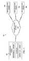
- FIG. 1is a schematic block diagram of an embodiment of a videoconferencing infrastructure within which a videoconferencing terminal constructed according to the principles of the disclosure may operate;
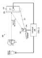
- FIG. 2is a side elevation view of an embodiment of a videoconferencing terminal, e.g., of the videoconferencing infrastructure of FIG. 1 , constructed according to the principles of the disclosure;
- FIG. 3is a flow diagram of one embodiment of a method of videoconferencing carried out according to the principles of the disclosure.
- the disclosed apparatussuch as a computer terminal, employs the front surface or screen of a monitor (e.g., a liquid crystal display (LCD) monitor) as a low efficiency mirror and a camera (e.g., a video camera) located either above, below or to the side of the monitor to capture an image of the user.
- a monitore.g., a liquid crystal display (LCD) monitor
- a camerae.g., a video camera located either above, below or to the side of the monitor to capture an image of the user.
- the light source illumination of the monitoris deactivated when the camera captures images.
- the light source illuminationmay be synchronously strobed with the exposures of the camera.
- the high strobe rate, for example at a frequency of 120 Hz, of the monitor's light sourcecan essentially make the strobe effect undetectable by a user, while timing the exposures of the camera with the “off” state of the light source ensures that the camera images do not include visual data originating from the monitor itself (e.g., a remote image being displayed on the monitor).
- the disclosed apparatusmay be a computer terminal that is used for videoconferencing (i.e., a videoconferencing terminal).
- the cameramay be positioned in front of a user and pointing towards the monitor.
- the monitormay be placed at a normal position in front of the user, pointing slightly downwards.
- the image of the useris displayed on the monitor (i.e., the user image is reflected therefrom) and aligned such that the user appears to be looking directly towards the camera.
- the user's image that is captured by the camerais enhanced by synchronizing the capturing of the reflected image with the deactivation of the light source illumination of the monitor.
- the monitormay be a LCD monitor used with a controller or computing device to effectively time interlace a regular image and a black image.
- a synchronization signal from, for example, the controllermay be used to time the exposures of the camera and the operation of the light source.
- the controllermay be integrated with the monitor, the camera or may be an independent computing device that provides the synchronization signal to the monitor and the camera.
- the synchronization signalcould be transmitted wirelessly and broadcast to multiple monitors and/or other devices in the room, such as environmental light systems.
- the synchronization signalcan be used to control other environmental effects associated with the monitor and camera. For example, the lighting of a user's face can improve the captured image of the user, but the glare of lights in the face is uncomfortable. As such, the lighting of the user's face could be timed to be synchronized with the camera exposures and off at other times. This would improve the efficiency of the lighting and generally reduce the perceived brightness of the lights by around fifty percent. Similarly, the ambient lighting of the room could be synchronized to appear normal to the local viewer, but “off” to the camera.
- FIG. 1is a schematic block diagram of one embodiment of a videoconferencing infrastructure 100 within which a videoconferencing terminal constructed according to the principles of the disclosure may operate.
- This embodiment of the videoconferencing infrastructure 100is centered about a telecommunications network 110 that is employed to interconnect two or more videoconferencing terminals 120 , 130 , 140 , 150 for communication of video signals or information, and perhaps also audio signals or information, therebetween.
- An alternative embodiment of the videoconferencing infrastructure 100is centered about a computer network, such as the Internet.
- Still another embodiment of the videoconferencing infrastructure 100involves a direct connection between two videoconferencing terminals, e.g., connection of the videoconferencing terminals 120 , 130 via a plain old telephone (POTS) network.
- POTSplain old telephone
- the videoconferencing terminals 120 , 130 , 140 , 150may include components typically included in a conventional videoconferencing terminal, such as, a microphone, a speaker, a monitor and controller. Additionally, the videoconferencing terminals 120 , 130 , 140 , 150 , may include a camera located in front of the monitor and positioned to face the monitor and capture an image reflected therefrom. The front or viewing side of the monitor is the screen-side of the monitor where displayed images are viewed.
- the microphonecan be configured to generate an audio signal based on acoustic energy received thereby, and the speaker can be configured to generate acoustic energy based on an audio signal received thereby.
- the monitorcan include a display screen that provides a visual output and the controller can be configured to direct the operation of the terminal. Unlike conventional terminals, the controller may also be configured to provide a synchronization signal to control operation of the camera with the light source of the monitor.
- the videoconferencing terminals 120 , 130 , 140 , 150may be computer terminals, including but not limited to, a personal computer, a laptop, a computing pad, a personal digital assistant (PDQ) or a mobile telephone.
- PDQpersonal digital assistant
- FIG. 2is a side elevation view of an embodiment of a videoconferencing terminal 200 , e.g., of the videoconferencing infrastructure of FIG. 1 , constructed according to the principles of the disclosure.
- the videoconferencing terminal 200includes a monitor 210 , a camera 220 and an exposure controller 230 .
- the monitor 210includes a screen 215 and a light source 217 (e.g., a backlight) and is configured to provide an image for viewing, such as, a remote image communicated over the telecommunications network 110 of FIG. 1 from a remote videoconferencing terminal.
- the remote imagemay be from a first location that is a remote location from the monitor 210 which is at a second location.
- the first location and the second locationmay be located proximate each other.
- the first location and the second locationmay be located in the same building or may be separated by a wall.
- the monitor 210may be a flat panel display (FPD) monitor.
- the monitor 210is a LCD monitor.
- the monitor 210is a liquid-crystal-on-silicon (LCoS) monitor.
- the monitor 210is another conventional or later-developed FPD technology that employs a light source to provide images for viewing.
- FPDflat panel display
- the monitor 210is a LCD monitor.
- the monitor 210is a liquid-crystal-on-silicon (LCoS) monitor.
- the monitor 210is another conventional or later-developed FPD technology that employs a light source to provide images for viewing.
- the monitor 210is configured to switch between a display mode and a reflecting mode.
- the monitor 210provides an image for viewing as in a conventional monitor.
- the light source 217is activated to provide the image on the screen 215 .
- the light source 217 of the monitoris deactivated to provide a black surface at the screen 215 to reflect a user image to be captured by the camera 220 .
- the camera 220is located in front of the monitor 210 and positioned to face the monitor 210 and capture an image reflected therefrom during the reflection mode.
- the camera 220may be a conventional webcam.
- the local imagemay be the face of a local user in front of the monitor 210 .
- the local usermay be, for example, employing the monitor 210 for a videoconferencing session or recording a video blog.
- the camera 220may be coupled to the monitor 210 via conventional audio-video cable (not shown) to transmit the captured image to the monitor 210 for, for example, transmission to another terminal for video conferencing. Wireless connections may also be employed.
- the camera 220includes a base 225 that is designed to support the camera 220 and allow the camera 220 to be tilted to adjust the field of view.
- a base 225that allows the field of view of the camera 220 to be adjusted.
- the field of viewmay be adjusted to align with the angle that the local image is reflected (i.e., the angle of reflection) from the monitor 210 .
- the camera 220may be coupled to a keyboard associated with the monitor 210 .
- the camera 220may be coupled to the keyboard via a conventional means.
- the camera 220may also be fastened to the monitor 210 via an arm 227 as indicated by the dashed line in FIG. 2 .
- the distance the camera 220 is extended from the monitor 210 or positioned in front of the monitor 210may be based on the type of monitor 210 (e.g., the size of the monitor 210 ). The distance may be known based on experimentation. In some embodiments, a particular distance for various types of monitors may be marked on the arm 227 to position the camera 220 .
- the arm 227may be mechanically coupled to the monitor 210 through conventional means and may be attached at various locations on the monitor 210 that allow the camera 220 to be positioned in front of the monitor 210 .
- the arm 227may support the camera 220 from the bottom of the monitor 210 .
- the arm 227may support the camera 210 from sides of the monitor 210 of from the top of the monitor 210 .
- the camera 220may be attached to the top side of the keyboard, to the left side or, as illustrated, to the right side of the keyboard.
- the exposure controller 230is configured to provide a timing signal that synchronizes the camera 220 to capture the reflected image during the reflecting mode. As such, the exposure controller 230 may operate switches to control the illumination of the screen 215 to alternate between the display mode and the reflecting mode.
- the exposure controller 230may be a computing device that is external to the monitor 210 and the camera 220 as illustrated in FIG. 2 . Additionally, as indicated by the dashed boxes in the monitor 210 and the camera 220 , the exposure controller 230 may be integrated with the monitor 210 or the camera 220 . As such, the exposure controller 230 may be integrated with a controller of the monitor 210 or a controller of the camera 220 .
- the exposure controller 230may be a processor typically included in an array-type LCD device that in addition to the various functions typically performed, such as directing the backplane for LCD pixels, is configured to perform the functions described herein.
- the exposure controller 230may be configured to direct the light source 217 to cycle between a display mode (an illumination cycle) and a reflecting mode (a black cycle).
- a display modethe light source 217 is on and the display pixels are illuminated.
- the reflecting modethe light source 217 is off and an image is reflected from the black screen.
- the percentage of time where the light source 217 is on versus when the light source 217 is offcan vary in different embodiments depending on the efficiency of the image sensors. In some embodiments, the light source 217 is cycled off 10% or about 10% of the time. In other embodiments, the light source 217 may cycle off up to or about to 50% of the time.
- the exposure controller 270may direct the light source 217 to cycle off within a range of 10% to 50% of the time. In some embodiments, the exposure controller 270 may direct the light source 217 to cycle off greater than 50% of the time. Increasing the reflection time may improve camera signal-to-noise ratio while decreasing the reflection time may reduce the apparent brightness of any environmental illumination. As such, both increasing and decreasing the reflection time can be beneficial depending on the various environments.
- the exposure controller 230provides the timing signal to switch the monitor 210 between the display mode and the reflecting mode at a frequency of 120 Hertz. In other embodiments, the timing signal may be generated at different frequencies. The switching between the display mode and the reflecting mode, however, is performed to minimize or completely reduce detection of the switching by the user.
- the exposure controller 230may be one of various conventional digital data processors that are programmed or store executable programs of sequences of software instructions to perform one or more of the above functions.
- the software instructions of such programsmay be encoded in machine-executable form on conventional digital data storage media, e.g., magnetic or optical disks, random-access memory (RAM), magnetic hard disks, flash memories, and/or read-only memory (ROM), to enable various types of digital data processors or computers to perform one, multiple or all of the above described functions.
- the timing signal generated by the exposure controller 230may also be employed to control operation of environmental effects associated with the monitor or the camera.
- the environmental effectsmay include ambient lighting wherein the ambient lighting is turned off during the reflecting mode.
- the environmental effects, including the ambient lightingmay be coupled to the exposure controller 230 through a wired connection as indicated in FIG. 2 .
- the connectionmay be wireless. Both the wireless and wired connections, for these and other connections associated with the exposure controller 230 , may be via conventional means.
- the exposure controller 230may alternate on/off images at a frequency of 120 Hz.
- the exposure controller 230may be a video adaptor that generates an electrical synchronization signal as the timing signal to control exposure time of the camera 220 to correspond with the frequency of the images being displayed.
- the video adaptormay be a Nvidia Quadro 570.
- imagesmay be continuously displayed on the monitor 210 and the timing signal may be used to synchronously enable strobing of the light source 217 (e.g., a LCD backlight) with exposures of the camera 220 .
- FIG. 3is a flow diagram of one embodiment of a method of videoconferencing carried out according to the principles of the disclosure.
- a videoconferencing terminal including a monitor and a camera as described with respect to FIG. 1 or FIG. 2may be employed for the method 300 .
- the methodbegins in a step 305 .
- a monitoris switched between a display mode and a reflecting mode. Switching between the modes may be controlled by a timing signal.
- the timing signalmay be generated by an exposure controller.
- the exposure controllermay be integrated with a monitor or a camera.
- a local image reflected from the monitor(i.e., a screen of the monitor) is captured in a step 320 .
- the local imagemay be captured by a camera located in front of the monitor and positioned to face the monitor.
- the local imageis reflected from the monitor at an angle of reflection and the camera captures the local image at the angle of reflection.
- the cameramay be mechanically coupled to the monitor.
- the local imagecan be captured to be displayed at another location.
- users at different locationsmay participate in a video conference.
- the local imagemay be of a local user of the monitor and the camera is positioned between the local user and the monitor.
- the light source of the monitoris deactivated by the timing signal. This reduces or eliminates light originating from the monitor.
- a remote imageis provided on the monitor during the display mode. While providing the remote image, the light source of the monitor is activated by the timing signal. As such, operation of the light source of the monitor is synchronized with the reflecting and display modes. In one embodiment, switching between the display mode and the reflecting mode may occur at a frequency of 120 Hertz.
- step 340operation of environmental effects associated with the monitor or the camera are controlled based on the display mode and the reflecting mode.
- the operation of the environmental effectsmay be controlled by the timing signal.
- the environmental effectsmay include ambient lighting for the monitor and camera.
- the method 300then ends in a step 340 .
Landscapes
- Engineering & Computer Science (AREA)
- Multimedia (AREA)
- Signal Processing (AREA)
- Two-Way Televisions, Distribution Of Moving Picture Or The Like (AREA)
Abstract
Description
Claims (20)
Priority Applications (2)
| Application Number | Priority Date | Filing Date | Title |
|---|---|---|---|
| US12/856,391US8421844B2 (en) | 2010-08-13 | 2010-08-13 | Apparatus for correcting gaze, a method of videoconferencing and a system therefor |
| PCT/US2011/046538WO2012021364A1 (en) | 2010-08-13 | 2011-08-04 | An apparatus for correcting gaze, a method and system of videoconferencing |
Applications Claiming Priority (1)
| Application Number | Priority Date | Filing Date | Title |
|---|---|---|---|
| US12/856,391US8421844B2 (en) | 2010-08-13 | 2010-08-13 | Apparatus for correcting gaze, a method of videoconferencing and a system therefor |
Publications (2)
| Publication Number | Publication Date |
|---|---|
| US20120038741A1 US20120038741A1 (en) | 2012-02-16 |
| US8421844B2true US8421844B2 (en) | 2013-04-16 |
Family
ID=44511548
Family Applications (1)
| Application Number | Title | Priority Date | Filing Date |
|---|---|---|---|
| US12/856,391Expired - Fee RelatedUS8421844B2 (en) | 2010-08-13 | 2010-08-13 | Apparatus for correcting gaze, a method of videoconferencing and a system therefor |
Country Status (2)
| Country | Link |
|---|---|
| US (1) | US8421844B2 (en) |
| WO (1) | WO2012021364A1 (en) |
Cited By (2)
| Publication number | Priority date | Publication date | Assignee | Title |
|---|---|---|---|---|
| US20120140017A1 (en)* | 2010-12-06 | 2012-06-07 | Electronics And Telecommunications Research Institute | Video displaying apparatus and controlling method thereof |
| US20150002609A1 (en)* | 2013-06-26 | 2015-01-01 | Avaya, Inc. | Automated field of view adjustment based on screen size |
Families Citing this family (2)
| Publication number | Priority date | Publication date | Assignee | Title |
|---|---|---|---|---|
| US9113036B2 (en)* | 2013-07-17 | 2015-08-18 | Ebay Inc. | Methods, systems, and apparatus for providing video communications |
| US20250168026A1 (en)* | 2023-11-19 | 2025-05-22 | Charter Communications Operating, Llc | Perceived eye-contact in live video conferencing systems |
Citations (55)
| Publication number | Priority date | Publication date | Assignee | Title |
|---|---|---|---|---|
| EP0385128A2 (en) | 1989-03-02 | 1990-09-05 | Alcatel N.V. | Video terminal |
| US5400069A (en) | 1993-06-16 | 1995-03-21 | Bell Communications Research, Inc. | Eye contact video-conferencing system and screen |
| US5438357A (en) | 1993-11-23 | 1995-08-01 | Mcnelley; Steve H. | Image manipulating teleconferencing system |
| US5500671A (en) | 1994-10-25 | 1996-03-19 | At&T Corp. | Video conference system and method of providing parallax correction and a sense of presence |
| US5537232A (en) | 1993-10-05 | 1996-07-16 | In Focus Systems, Inc. | Reflection hologram multiple-color filter array formed by sequential exposure to a light source |
| EP0812106A2 (en) | 1996-06-07 | 1997-12-10 | NOKIA TECHNOLOGY GmbH | Method for controlling exposure of a video camera in video conference equipment |
| US5801758A (en)* | 1995-06-21 | 1998-09-01 | Apple Computer, Inc. | System and method for image capture and display utilizing time sharing across a single, two-way optical path |
| EP1018041A1 (en) | 1997-01-07 | 2000-07-12 | DaimlerChrysler AG | Screen for front laser projection |
| WO2000047001A1 (en) | 1999-02-03 | 2000-08-10 | Ldt Gmbh & Co. Laser-Display-Technologie Kg | Image representation system |
| US6323984B1 (en) | 2000-10-11 | 2001-11-27 | Silicon Light Machines | Method and apparatus for reducing laser speckle |
| US6340230B1 (en) | 2000-03-10 | 2002-01-22 | Optical Coating Laboratory, Inc. | Method of using a retarder plate to improve contrast in a reflective imaging system |
| EP1176803A1 (en) | 2000-07-27 | 2002-01-30 | Eastman Kodak Company | A method and apparatus for printing images onto a photosensitive media using reflective liquid crystal modulators |
| US6385352B1 (en) | 1994-10-26 | 2002-05-07 | Symbol Technologies, Inc. | System and method for reading and comparing two-dimensional images |
| US20020063774A1 (en) | 2000-11-29 | 2002-05-30 | Hillis William Daniel | Method and apparatus for maintaining eye contact in teleconferencing using reflected images |
| EP1283434A2 (en) | 2001-08-08 | 2003-02-12 | Eastman Kodak Company | Electro-optic despeckling modulator and method of use |
| WO2004064410A1 (en) | 2003-01-08 | 2004-07-29 | Explay Ltd. | An image projecting device and method |
| US20040239880A1 (en) | 2001-07-06 | 2004-12-02 | Yuval Kapellner | Image projecting device and method |
| US6882358B1 (en)* | 2002-10-02 | 2005-04-19 | Terabeam Corporation | Apparatus, system and method for enabling eye-to-eye contact in video conferences |
| US20050099605A1 (en) | 2000-09-15 | 2005-05-12 | Georges Buchner | Interactive audio-visual system |
| US6926850B2 (en) | 2001-07-26 | 2005-08-09 | Lucent Technologies Inc. | Method for making micro lenses |
| EP1571467A2 (en) | 2004-02-27 | 2005-09-07 | Bose Corporation | Selectively reflecting optical component, in particular reflection screen |
| US20050231734A1 (en) | 2004-04-19 | 2005-10-20 | Ivp Integrated Vision Products Ab | Measuring apparatus and method in a distribution system |
| US20060007222A1 (en) | 2004-06-21 | 2006-01-12 | Apple Computer, Inc. | Integrated sensing display |
| EP1640799A1 (en) | 2003-06-06 | 2006-03-29 | Matsushita Electric Industrial Co., Ltd. | Laser projector |
| US7034866B1 (en) | 2000-11-22 | 2006-04-25 | Koninklijke Philips Electronics N.V. | Combined display-camera for an image processing system |
| EP1734771A1 (en) | 2005-06-14 | 2006-12-20 | SONY DEUTSCHLAND GmbH | Illumination optics, illumination unit and image generation unit |
| US20070002130A1 (en) | 2005-06-21 | 2007-01-04 | David Hartkop | Method and apparatus for maintaining eye contact during person-to-person video telecommunication |
| US20070046907A1 (en) | 2005-08-31 | 2007-03-01 | Lg Electronics Inc. | Portable projector |
| WO2007029649A1 (en) | 2005-09-05 | 2007-03-15 | Matsushita Electric Industrial Co., Ltd. | Filter for display device |
| US20070120879A1 (en) | 2005-10-17 | 2007-05-31 | I2Ic Corporation | Combined Video Display and Camera System |
| US7239879B2 (en) | 2003-11-26 | 2007-07-03 | Lucent Technologies Inc. | Opportunistic beamforming and scheduling of users in a communication system |
| US20070247417A1 (en) | 2006-04-25 | 2007-10-25 | Seiko Epson Corporation | Electrophoresis display device, method of driving electrophoresis display device, and electronic apparatus |
| US20070273839A1 (en) | 2006-05-25 | 2007-11-29 | Funai Electric Co., Ltd. | Video Projector |
| WO2007138542A2 (en) | 2006-05-25 | 2007-12-06 | Udayan Kanade | A system of displaying and capturing images using non-planar mirrors |
| US20080012936A1 (en) | 2004-04-21 | 2008-01-17 | White Peter M | 3-D Displays and Telepresence Systems and Methods Therefore |
| US7370972B2 (en) | 2003-12-24 | 2008-05-13 | Matsushita Electric Industrial Co., Ltd. | Two-dimensional image display device |
| US20080212040A1 (en) | 2007-03-02 | 2008-09-04 | Vladimir Anatolyevich Aksyuk | Holographic MEMS operated optical projectors |
| US20080212034A1 (en) | 2007-03-02 | 2008-09-04 | Lucent Technologies Inc. | Speckle reduction in laser-projector images |
| US20080219303A1 (en) | 2007-03-02 | 2008-09-11 | Lucent Technologies Inc. | Color mixing light source and color control data system |
| US7440158B2 (en) | 2007-03-02 | 2008-10-21 | Lucent Technologies Inc. | Direct optical image projectors |
| US20090041298A1 (en) | 2007-08-06 | 2009-02-12 | Sandler Michael S | Image capture system and method |
| US20090122572A1 (en) | 2007-11-08 | 2009-05-14 | The Regents Of The University Of California | Apparatus configured to provide functional and aesthetic lighting from a fan |
| US20090185251A1 (en) | 2008-01-22 | 2009-07-23 | Alcatel-Lucent Usa, Incorporated | Oscillating mirror for image projection |
| US20090185140A1 (en) | 2008-01-22 | 2009-07-23 | Lucent Technologies, Inc. | Multi-color light source |
| US20090184976A1 (en) | 2008-01-22 | 2009-07-23 | Alcatel-Lucent | System and Method for Color-Compensating a Video Signal Having Reduced Computational Requirements |
| US20090185141A1 (en) | 2008-01-22 | 2009-07-23 | Lucent Technologies, Inc. | Diffuser configuration for an image projector |
| US20090184659A1 (en) | 2008-01-22 | 2009-07-23 | Gang Chen | Time division multiplexing a DC-to-DC voltage converter |
| US20100039380A1 (en) | 2004-10-25 | 2010-02-18 | Graphics Properties Holdings, Inc. | Movable Audio/Video Communication Interface System |
| US20100073456A1 (en) | 2008-09-25 | 2010-03-25 | Lucent Technologies Inc. | Videoconferencing terminal and method of operation thereof to maintain eye contact |
| US20100173436A1 (en) | 2009-01-05 | 2010-07-08 | Dalsa Semiconductor Inc. | Method of making biomems devices |
| US20100174443A1 (en) | 2007-06-15 | 2010-07-08 | Honda Motor Co., Ltd. | Maintenance time notification device |
| US7763546B2 (en) | 2006-08-02 | 2010-07-27 | Qualcomm Mems Technologies, Inc. | Methods for reducing surface charges during the manufacture of microelectromechanical systems devices |
| US7808540B2 (en) | 2007-01-09 | 2010-10-05 | Eastman Kodak Company | Image capture and integrated display apparatus |
| US20100302344A1 (en)* | 2009-05-28 | 2010-12-02 | Microsoft Corporation | Establishing eye contact in video conferencing |
| US8154582B2 (en) | 2007-10-19 | 2012-04-10 | Eastman Kodak Company | Display device with capture capabilities |
- 2010
- 2010-08-13USUS12/856,391patent/US8421844B2/ennot_activeExpired - Fee Related
- 2011
- 2011-08-04WOPCT/US2011/046538patent/WO2012021364A1/enactiveApplication Filing
Patent Citations (57)
| Publication number | Priority date | Publication date | Assignee | Title |
|---|---|---|---|---|
| EP0385128A2 (en) | 1989-03-02 | 1990-09-05 | Alcatel N.V. | Video terminal |
| US5400069A (en) | 1993-06-16 | 1995-03-21 | Bell Communications Research, Inc. | Eye contact video-conferencing system and screen |
| US5537232A (en) | 1993-10-05 | 1996-07-16 | In Focus Systems, Inc. | Reflection hologram multiple-color filter array formed by sequential exposure to a light source |
| US5438357A (en) | 1993-11-23 | 1995-08-01 | Mcnelley; Steve H. | Image manipulating teleconferencing system |
| US5500671A (en) | 1994-10-25 | 1996-03-19 | At&T Corp. | Video conference system and method of providing parallax correction and a sense of presence |
| US6385352B1 (en) | 1994-10-26 | 2002-05-07 | Symbol Technologies, Inc. | System and method for reading and comparing two-dimensional images |
| US5801758A (en)* | 1995-06-21 | 1998-09-01 | Apple Computer, Inc. | System and method for image capture and display utilizing time sharing across a single, two-way optical path |
| EP0812106A2 (en) | 1996-06-07 | 1997-12-10 | NOKIA TECHNOLOGY GmbH | Method for controlling exposure of a video camera in video conference equipment |
| EP1018041A1 (en) | 1997-01-07 | 2000-07-12 | DaimlerChrysler AG | Screen for front laser projection |
| US6392766B1 (en) | 1997-01-07 | 2002-05-21 | Daimlerchrysler Ag | Screen for front laser projection |
| WO2000047001A1 (en) | 1999-02-03 | 2000-08-10 | Ldt Gmbh & Co. Laser-Display-Technologie Kg | Image representation system |
| US6340230B1 (en) | 2000-03-10 | 2002-01-22 | Optical Coating Laboratory, Inc. | Method of using a retarder plate to improve contrast in a reflective imaging system |
| EP1176803A1 (en) | 2000-07-27 | 2002-01-30 | Eastman Kodak Company | A method and apparatus for printing images onto a photosensitive media using reflective liquid crystal modulators |
| US20050099605A1 (en) | 2000-09-15 | 2005-05-12 | Georges Buchner | Interactive audio-visual system |
| US6323984B1 (en) | 2000-10-11 | 2001-11-27 | Silicon Light Machines | Method and apparatus for reducing laser speckle |
| US7034866B1 (en) | 2000-11-22 | 2006-04-25 | Koninklijke Philips Electronics N.V. | Combined display-camera for an image processing system |
| US20020063774A1 (en) | 2000-11-29 | 2002-05-30 | Hillis William Daniel | Method and apparatus for maintaining eye contact in teleconferencing using reflected images |
| US20040239880A1 (en) | 2001-07-06 | 2004-12-02 | Yuval Kapellner | Image projecting device and method |
| US6926850B2 (en) | 2001-07-26 | 2005-08-09 | Lucent Technologies Inc. | Method for making micro lenses |
| EP1283434A2 (en) | 2001-08-08 | 2003-02-12 | Eastman Kodak Company | Electro-optic despeckling modulator and method of use |
| US6791739B2 (en) | 2001-08-08 | 2004-09-14 | Eastman Kodak Company | Electro-optic despeckling modulator and method of use |
| US6882358B1 (en)* | 2002-10-02 | 2005-04-19 | Terabeam Corporation | Apparatus, system and method for enabling eye-to-eye contact in video conferences |
| WO2004064410A1 (en) | 2003-01-08 | 2004-07-29 | Explay Ltd. | An image projecting device and method |
| EP1640799A1 (en) | 2003-06-06 | 2006-03-29 | Matsushita Electric Industrial Co., Ltd. | Laser projector |
| US7239879B2 (en) | 2003-11-26 | 2007-07-03 | Lucent Technologies Inc. | Opportunistic beamforming and scheduling of users in a communication system |
| US7370972B2 (en) | 2003-12-24 | 2008-05-13 | Matsushita Electric Industrial Co., Ltd. | Two-dimensional image display device |
| EP1571467A2 (en) | 2004-02-27 | 2005-09-07 | Bose Corporation | Selectively reflecting optical component, in particular reflection screen |
| US20050231734A1 (en) | 2004-04-19 | 2005-10-20 | Ivp Integrated Vision Products Ab | Measuring apparatus and method in a distribution system |
| US20080012936A1 (en) | 2004-04-21 | 2008-01-17 | White Peter M | 3-D Displays and Telepresence Systems and Methods Therefore |
| US20060007222A1 (en) | 2004-06-21 | 2006-01-12 | Apple Computer, Inc. | Integrated sensing display |
| US20100039380A1 (en) | 2004-10-25 | 2010-02-18 | Graphics Properties Holdings, Inc. | Movable Audio/Video Communication Interface System |
| EP1734771A1 (en) | 2005-06-14 | 2006-12-20 | SONY DEUTSCHLAND GmbH | Illumination optics, illumination unit and image generation unit |
| US20070002130A1 (en) | 2005-06-21 | 2007-01-04 | David Hartkop | Method and apparatus for maintaining eye contact during person-to-person video telecommunication |
| US20070046907A1 (en) | 2005-08-31 | 2007-03-01 | Lg Electronics Inc. | Portable projector |
| WO2007029649A1 (en) | 2005-09-05 | 2007-03-15 | Matsushita Electric Industrial Co., Ltd. | Filter for display device |
| US20070120879A1 (en) | 2005-10-17 | 2007-05-31 | I2Ic Corporation | Combined Video Display and Camera System |
| US20070247417A1 (en) | 2006-04-25 | 2007-10-25 | Seiko Epson Corporation | Electrophoresis display device, method of driving electrophoresis display device, and electronic apparatus |
| WO2007138542A2 (en) | 2006-05-25 | 2007-12-06 | Udayan Kanade | A system of displaying and capturing images using non-planar mirrors |
| US20070273839A1 (en) | 2006-05-25 | 2007-11-29 | Funai Electric Co., Ltd. | Video Projector |
| US7763546B2 (en) | 2006-08-02 | 2010-07-27 | Qualcomm Mems Technologies, Inc. | Methods for reducing surface charges during the manufacture of microelectromechanical systems devices |
| US7808540B2 (en) | 2007-01-09 | 2010-10-05 | Eastman Kodak Company | Image capture and integrated display apparatus |
| US20080212040A1 (en) | 2007-03-02 | 2008-09-04 | Vladimir Anatolyevich Aksyuk | Holographic MEMS operated optical projectors |
| US20080212034A1 (en) | 2007-03-02 | 2008-09-04 | Lucent Technologies Inc. | Speckle reduction in laser-projector images |
| US20080219303A1 (en) | 2007-03-02 | 2008-09-11 | Lucent Technologies Inc. | Color mixing light source and color control data system |
| US7440158B2 (en) | 2007-03-02 | 2008-10-21 | Lucent Technologies Inc. | Direct optical image projectors |
| US20100174443A1 (en) | 2007-06-15 | 2010-07-08 | Honda Motor Co., Ltd. | Maintenance time notification device |
| US20090041298A1 (en) | 2007-08-06 | 2009-02-12 | Sandler Michael S | Image capture system and method |
| US8154582B2 (en) | 2007-10-19 | 2012-04-10 | Eastman Kodak Company | Display device with capture capabilities |
| US20090122572A1 (en) | 2007-11-08 | 2009-05-14 | The Regents Of The University Of California | Apparatus configured to provide functional and aesthetic lighting from a fan |
| US20090185140A1 (en) | 2008-01-22 | 2009-07-23 | Lucent Technologies, Inc. | Multi-color light source |
| US20090184659A1 (en) | 2008-01-22 | 2009-07-23 | Gang Chen | Time division multiplexing a DC-to-DC voltage converter |
| US20090185141A1 (en) | 2008-01-22 | 2009-07-23 | Lucent Technologies, Inc. | Diffuser configuration for an image projector |
| US20090184976A1 (en) | 2008-01-22 | 2009-07-23 | Alcatel-Lucent | System and Method for Color-Compensating a Video Signal Having Reduced Computational Requirements |
| US20090185251A1 (en) | 2008-01-22 | 2009-07-23 | Alcatel-Lucent Usa, Incorporated | Oscillating mirror for image projection |
| US20100073456A1 (en) | 2008-09-25 | 2010-03-25 | Lucent Technologies Inc. | Videoconferencing terminal and method of operation thereof to maintain eye contact |
| US20100173436A1 (en) | 2009-01-05 | 2010-07-08 | Dalsa Semiconductor Inc. | Method of making biomems devices |
| US20100302344A1 (en)* | 2009-05-28 | 2010-12-02 | Microsoft Corporation | Establishing eye contact in video conferencing |
Non-Patent Citations (18)
| Title |
|---|
| "DC-DC Converted Basics" published on line at: http://www.powerdesigners.com/InfoWeb /design-center/articles/DC-DC/converter.shtm; 12 pages. |
| "Electrophoresis," Liquid Crystals & Photonics Group-Ghent University (Belgium), http://trappist.elis.ugent.be/elisgroups/lcd/research/elektink.php, Aug. 9, 2010, 12 pages. |
| "How mirasol Displays Work: Micro-electro-mechanical Systems (MEMS) Drive IMOD Reflective Technology," www.mirasoldisplays.com/mobile-display-imod-technology, 1 page. |
| "S-334-Ultra-Long-Range Piezo Tip/Tilt Mirror"; Moving the NanoWorld, www.pi.we; 2 Pages. |
| "TFT LCD Specification," Pixel Qi, Doc No. PQ003, Issued Date: Jun. 28, 2010, Model No. PQ 3Qi-01, Version 1.0, 23 pages. |
| C. Bolle et al, "Imaging Terminal", filed Dec. 8, 2009, U.S. Appl. No. 12/633,656, 22 pages. |
| C. Bolle et al, "Videoconferencing Terminal With a Persistence of Vision Display and a Method of Operation Thereof to Maintain Eye Contact", filed Dec. 17, 2009, U.S. Appl. No. 12/640,998, 36 pages. |
| Greywall, Dennis S., et al.; "Crystalline Silicon Tilting Mirrors for Optical Cross-Connect Switches"; Journal of Microelectromechanical Systems, vol. 12, No. 5, Oct. 2003, pp. 708-712. |
| H. Ishii et al, "ClearBoard: A Seamless Medium for Shared Drawing and Conversation with Eye Contact", CHI '92, (May 3-7, 1992), pp. 525-532. |
| J.W. Goodman, "Some Fundamental Properties of Speckle" Journal of the Optical Society of America, vol. 66, No. 11, pp. 1145-1150, Nov. 1976. |
| K-H Tan et al, "ConnectBoard: A remote collaboration system that supports gaze-aware interaction and sharing", 2009 IEEE International Workshop on Multimedia Signal Processing, MMSP '09, (Oct. 5-7, 2009), 6 pages. |
| M. Gross et al, "blue-c: A Spatially Immersive Display and 3D Video Portal for Telepresence", project webpage: http://bluec.ethz.ch/,ACM 0730-0301/03/0700-0819, (2003) pp. 819-827. |
| M. Kuechler et al, "HoloPort-A Device for Simultaneous Video and Data Conferencing Featuring Gaze Awareness", In Proceedings of the 2006 IEEE Virtual Reality Conference (VR '06). (2006) pp. 81-87. |
| Matthews; U.S. Appl. No. 12/855,186; "A Gaze Correcting Apparatus, a Method of Videoconferencing and a Videoconferencing System"; filed Aug. 12, 2010. |
| Rickers, et al.; "Design and manufacture of spectrally selective reflecting coatings for the use with laser display projection screens;" Applied Optics, OSA, Optical Society of America, Washington, DC; vol. 41, No. 16, Jun. 1, 2002, pp. 3097-3106; XP-002346084. |
| S. Izadi et al, "Going Beyond the Display: A Surface Technology with an Electronically Switchable Diffuser", UIST '08, (Oct. 19-22, 2008), Monterey, CA, pp. 269-278. |
| S. Shiwa et al, "A Large-Screen Visual Telecommunication Device Enabling Eye Contact", SID 91 Digest, ISSN0097-0966x/91/0000-327 (1991), pp. 327-328. |
| SC Kerigan, et al, "Perceived Speckle Reduction in Projection Display Systems" IP.com Journal, IP.com Inc., West Henrietta, NY, pp. 9-11, Jul. 1, 1997, XP-013106711. |
Cited By (4)
| Publication number | Priority date | Publication date | Assignee | Title |
|---|---|---|---|---|
| US20120140017A1 (en)* | 2010-12-06 | 2012-06-07 | Electronics And Telecommunications Research Institute | Video displaying apparatus and controlling method thereof |
| US8760493B2 (en)* | 2010-12-06 | 2014-06-24 | Electronics And Telecommunications Research Institute | Video displaying apparatus and controlling method thereof |
| US20150002609A1 (en)* | 2013-06-26 | 2015-01-01 | Avaya, Inc. | Automated field of view adjustment based on screen size |
| US9088689B2 (en)* | 2013-06-26 | 2015-07-21 | Avaya, Inc. | Automated field of view adjustment based on screen size |
Also Published As
| Publication number | Publication date |
|---|---|
| WO2012021364A1 (en) | 2012-02-16 |
| US20120038741A1 (en) | 2012-02-16 |
Similar Documents
| Publication | Publication Date | Title |
|---|---|---|
| US20070070177A1 (en) | Visual and aural perspective management for enhanced interactive video telepresence | |
| US8638354B2 (en) | Immersive video conference system | |
| EP2308230B1 (en) | Live telepresence system | |
| RU2518218C2 (en) | Telepresence system, telepresence method and video collection device | |
| US20110216153A1 (en) | Digital conferencing for mobile devices | |
| US20110134205A1 (en) | Imaging terminal | |
| US20110096137A1 (en) | Audiovisual Feedback To Users Of Video Conferencing Applications | |
| US9270933B1 (en) | System and method for face-to-face video communication | |
| US9313452B2 (en) | System and method for providing retracting optics in a video conferencing environment | |
| CN103493480A (en) | Video conferencing display device | |
| US9253442B1 (en) | Holopresence system | |
| US20210367985A1 (en) | Immersive telepresence video conference system | |
| US8421844B2 (en) | Apparatus for correcting gaze, a method of videoconferencing and a system therefor | |
| US20120038738A1 (en) | Gaze correcting apparatus, a method of videoconferencing and a videoconferencing system | |
| US7746373B2 (en) | Device for viewing images, such as for videoconference facilities, related system, network and method of use | |
| CN105306872A (en) | Method, apparatus and system for controlling multipoint video conference | |
| US7190388B2 (en) | Communication terminal and system | |
| KR101099369B1 (en) | Multi-party video conferencing system and method | |
| WO2011071700A2 (en) | Imaging terminal | |
| US11972505B2 (en) | Augmented image overlay on external panel | |
| JP2005303683A (en) | Image transceiver | |
| JPH0481088A (en) | Coincident glance type figure picture display image pickup device | |
| CN102685443B (en) | System and method for a multipoint video conference | |
| CN115412702A (en) | Conference terminal and video wall integrated equipment and system | |
| US20250168026A1 (en) | Perceived eye-contact in live video conferencing systems |
Legal Events
| Date | Code | Title | Description |
|---|---|---|---|
| AS | Assignment | Owner name:ALCATEL-LUCENT USA, INCORPORATED, NEW JERSEY Free format text:ASSIGNMENT OF ASSIGNORS INTEREST;ASSIGNOR:MATTHEWS, KIM N.;REEL/FRAME:024836/0841 Effective date:20100813 | |
| AS | Assignment | Owner name:ALCATEL LUCENT, FRANCE Free format text:ASSIGNMENT OF ASSIGNORS INTEREST;ASSIGNOR:ALCATEL-LUCENT USA INC.;REEL/FRAME:027233/0424 Effective date:20111115 | |
| FEPP | Fee payment procedure | Free format text:PAYOR NUMBER ASSIGNED (ORIGINAL EVENT CODE: ASPN); ENTITY STATUS OF PATENT OWNER: LARGE ENTITY | |
| AS | Assignment | Owner name:CREDIT SUISSE AG, NEW YORK Free format text:SECURITY INTEREST;ASSIGNOR:ALCATEL-LUCENT USA INC.;REEL/FRAME:030510/0627 Effective date:20130130 | |
| STCF | Information on status: patent grant | Free format text:PATENTED CASE | |
| FEPP | Fee payment procedure | Free format text:PAYER NUMBER DE-ASSIGNED (ORIGINAL EVENT CODE: RMPN); ENTITY STATUS OF PATENT OWNER: LARGE ENTITY Free format text:PAYOR NUMBER ASSIGNED (ORIGINAL EVENT CODE: ASPN); ENTITY STATUS OF PATENT OWNER: LARGE ENTITY | |
| AS | Assignment | Owner name:SOUND VIEW INNOVATIONS, LLC, NEW JERSEY Free format text:ASSIGNMENT OF ASSIGNORS INTEREST;ASSIGNOR:ALCATEL LUCENT;REEL/FRAME:033416/0763 Effective date:20140630 | |
| AS | Assignment | Owner name:ALCATEL-LUCENT USA INC., NEW JERSEY Free format text:RELEASE BY SECURED PARTY;ASSIGNOR:CREDIT SUISSE AG;REEL/FRAME:033949/0016 Effective date:20140819 | |
| FPAY | Fee payment | Year of fee payment:4 | |
| AS | Assignment | Owner name:PIECE FUTURE PTE LTD, SINGAPORE Free format text:ASSIGNMENT OF ASSIGNORS INTEREST;ASSIGNOR:SOUND VIEW INNOVATIONS, LLC;REEL/FRAME:052519/0440 Effective date:20200301 | |
| FEPP | Fee payment procedure | Free format text:MAINTENANCE FEE REMINDER MAILED (ORIGINAL EVENT CODE: REM.); ENTITY STATUS OF PATENT OWNER: LARGE ENTITY | |
| LAPS | Lapse for failure to pay maintenance fees | Free format text:PATENT EXPIRED FOR FAILURE TO PAY MAINTENANCE FEES (ORIGINAL EVENT CODE: EXP.); ENTITY STATUS OF PATENT OWNER: LARGE ENTITY | |
| STCH | Information on status: patent discontinuation | Free format text:PATENT EXPIRED DUE TO NONPAYMENT OF MAINTENANCE FEES UNDER 37 CFR 1.362 | |
| FP | Lapsed due to failure to pay maintenance fee | Effective date:20210416 |