US8421407B2 - Inductively coupled work surfaces - Google Patents
Inductively coupled work surfacesDownload PDFInfo
- Publication number
- US8421407B2 US8421407B2US12/391,698US39169809AUS8421407B2US 8421407 B2US8421407 B2US 8421407B2US 39169809 AUS39169809 AUS 39169809AUS 8421407 B2US8421407 B2US 8421407B2
- Authority
- US
- United States
- Prior art keywords
- work surface
- work
- primary coil
- inductively coupled
- housing
- Prior art date
- Legal status (The legal status is an assumption and is not a legal conclusion. Google has not performed a legal analysis and makes no representation as to the accuracy of the status listed.)
- Expired - Fee Related
Links
- 239000012780transparent materialSubstances0.000claimsdescription4
- 238000009420retrofittingMethods0.000claimsdescription2
- 229920001690polydopaminePolymers0.000abstractdescription8
- 238000005516engineering processMethods0.000description3
- 238000000034methodMethods0.000description2
- 229920005372Plexiglas®Polymers0.000description1
- 241001310793PodiumSpecies0.000description1
- 230000008878couplingEffects0.000description1
- 238000010168coupling processMethods0.000description1
- 238000005859coupling reactionMethods0.000description1
- 238000005286illuminationMethods0.000description1
- 230000001939inductive effectEffects0.000description1
- 238000009434installationMethods0.000description1
- 239000004926polymethyl methacrylateSubstances0.000description1
Images


Classifications
- A—HUMAN NECESSITIES
- A47—FURNITURE; DOMESTIC ARTICLES OR APPLIANCES; COFFEE MILLS; SPICE MILLS; SUCTION CLEANERS IN GENERAL
- A47B—TABLES; DESKS; OFFICE FURNITURE; CABINETS; DRAWERS; GENERAL DETAILS OF FURNITURE
- A47B96/00—Details of cabinets, racks or shelf units not covered by a single one of groups A47B43/00 - A47B95/00; General details of furniture
- A47B96/18—Tops specially designed for working on
- B—PERFORMING OPERATIONS; TRANSPORTING
- B25—HAND TOOLS; PORTABLE POWER-DRIVEN TOOLS; MANIPULATORS
- B25H—WORKSHOP EQUIPMENT, e.g. FOR MARKING-OUT WORK; STORAGE MEANS FOR WORKSHOPS
- B25H1/00—Work benches; Portable stands or supports for positioning portable tools or work to be operated on thereby
- B25H1/02—Work benches; Portable stands or supports for positioning portable tools or work to be operated on thereby of table type
- H—ELECTRICITY
- H02—GENERATION; CONVERSION OR DISTRIBUTION OF ELECTRIC POWER
- H02J—CIRCUIT ARRANGEMENTS OR SYSTEMS FOR SUPPLYING OR DISTRIBUTING ELECTRIC POWER; SYSTEMS FOR STORING ELECTRIC ENERGY
- H02J50/00—Circuit arrangements or systems for wireless supply or distribution of electric power
- H02J50/10—Circuit arrangements or systems for wireless supply or distribution of electric power using inductive coupling
- H—ELECTRICITY
- H02—GENERATION; CONVERSION OR DISTRIBUTION OF ELECTRIC POWER
- H02J—CIRCUIT ARRANGEMENTS OR SYSTEMS FOR SUPPLYING OR DISTRIBUTING ELECTRIC POWER; SYSTEMS FOR STORING ELECTRIC ENERGY
- H02J7/00—Circuit arrangements for charging or depolarising batteries or for supplying loads from batteries
- H02J7/0042—Circuit arrangements for charging or depolarising batteries or for supplying loads from batteries characterised by the mechanical construction
- H02J7/0044—Circuit arrangements for charging or depolarising batteries or for supplying loads from batteries characterised by the mechanical construction specially adapted for holding portable devices containing batteries
- H—ELECTRICITY
- H01—ELECTRIC ELEMENTS
- H01F—MAGNETS; INDUCTANCES; TRANSFORMERS; SELECTION OF MATERIALS FOR THEIR MAGNETIC PROPERTIES
- H01F38/00—Adaptations of transformers or inductances for specific applications or functions
- H01F38/14—Inductive couplings
Definitions
- This circuitdynamically seeks resonance and optimizes power transfer from a primary coil to a secondary device with a secondary coil. This power transfer can occur under multiple, varying load conditions.
- the primary supply circuitadapts its operation to match the needs of the secondary devices being supplied with power.
- the circuitalso allows the primary supply circuit to supply power to multiple secondary devices simultaneously.
- Intelligent, inductively coupled power circuitshave been developed to transfer power from a source to a device without the need for a wired connection.
- Primary coilsinductively couple power to secondary coils integrated into devices such as laptop computers, PDAs, cell phones, and power tools.
- Embodiments of the present inventionincorporate this technology into home and industrial work surfaces.
- Primary coils integrated into work surfacesinductively couple power to secondary coils integrated into devices such as laptop computers, PDAs, cell phones, and power tools.
- Work surfacesmay be home work surfaces such as tables and work benches.
- Primary coilsmay also be integrated into industrial work surfaces such as industrial ergonomic work benches.
- Inductively coupled work surfacesmay also be installed in vehicles.
- the vehicle work surfacecould be installed in the interior of the vehicle, or a retractable work surface could be installed such that it is accessible from the exterior of the vehicle.
- Primary coils of low, medium, and high powercan be integrated into work surfaces in any position, number, and combination.
- Indicators, such as LEDs, on a work surfacemay show where devices containing secondary coils should be placed to charge.
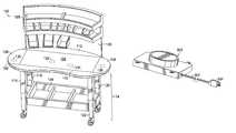
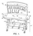
- FIG. 1is a perspective view of an ergonomic work bench
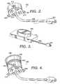
- FIG. 2is a perspective view of an embodiment of a low power primary coil
- FIG. 3is a perspective view of an embodiment of a medium power primary coil
- FIG. 4is a perspective view of an embodiment of a primary coil with an adjustable housing
- FIG. 5is a perspective view of a work bench with low and medium power primary coils installed
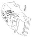
- FIG. 6is a partial perspective view of an inductively coupled work surface installed in a vehicle
- FIG. 7is a partial perspective view with parts broken away of an inductively coupled work surface installed in a vehicle
- FIG. 8is an enlarged partial perspective view of a tool containing a secondary coil charging on the inductively coupled work surface of FIG. 7 ;
- FIG. 9is a perspective view of an inductively coupled work surface charging devices containing secondary coils
- FIG. 10is a partial perspective view with parts broken away of an inductively coupled work surface installed in a vehicle
- FIG. 11is a perspective view of a retractable, inductively coupled work surface installed in a vehicle.
- FIG. 12is a perspective view of a retractable, inductively coupled work surface installed in a vehicle.
- Inductively coupled power circuitsmay be used to power and recharge cordless devices, including cell phones, PDAs, flashlights, laptop computers, and power tools.
- Each cordless devicehas a secondary coil.
- the primary coil required to create the inductively coupled power circuitmay be integrated into an industrial or home work surface. Examples of such surfaces with integrated primary coils include a table, a home work bench, an industrial work bench, an ergonomic work bench, an industrial ergonomic workbench, a mobile work surface in a vehicle, a retractable work surface, and a retractable work surface in a vehicle.
- FIG. 1illustrates an ergonomic work bench 100 .
- Work surface 102 of work bench 100comprises central work surface 104 , work surface side wings 106 and 108 , and work surface front and rear wings 110 and 112 .
- Some embodimentsmay include, in addition to central work surface 104 , only work surface side wing 106 , work surface side wing 108 , work surface front wing 110 , or work surface rear wing 112 . Additional embodiments may include all wings or any combination of wings.
- work surface side wings 106 and 108 and work surface front and rear wings 110 and 112are curved such that they form an ergonomic work surface when attached to central work surface 104 .
- Work surface side wings 106 and 108 and work surface front and rear wings 110 and 112may be attached to central work surface 104 by screws, bolts, or any other connection mechanism.
- work surface side wings 106 and 108 and work surface front and rear wings 110 and 112are thinner than central work surface 104 but have an extended edge substantially as thick as central work surface 104 . This allows the wings to be screwed or bolted through the extended edge into the side of central work surface 104 .
- Other means of connectionsuch as support beams extending beneath central work surface 104 and work surface side wings 106 and 108 and work surface front and rear wings 110 and 112 , are also contemplated.
- Support structure 114comprises support members 116 , 118 , 120 , and 122 .
- support membersmay be attached to wheels.
- support membersmay terminate in a substantially flat base.
- Storage tray 124is attached in the space bounded by support members 116 , 118 , 120 , and 122 .
- storage tray 124may be attached or rest on horizontal support members that run between support members 116 , 118 , 120 , and 122 .
- Work station shield 126may be attached to work surface rear wing 112 , central work surface 104 , or support structure 114 .
- Storage tray 128is attached to work station shield 126 .
- Work station shield 126 and storage tray 128are curved in substantially the same manner as work surface rear wing 112 to create an ergonomic work space.
- the concavity of the curvebrings the furthest portions of work bench 100 nearer to a user than if the concave portions were linear.
- Inductively coupled power circuitsmay be incorporated into a work bench such as work bench 100 of FIG. 1 .
- Integrated primary coils for such power circuitsare indicated by coil location indicators 130 , 132 , 134 , and 136 .
- Coil location indicators 130 , 132 , 134 , and 136do not necessarily indicate coil size or charging area, which depends upon whether a particular primary coil is low, medium, or high power.
- FIG. 2-4illustrate embodiments of primary coils that could be incorporated into a work bench.
- Primary coilsmay be designed to provide a low, medium, or high quantity of power.
- FIG. 2illustrates a low power primary coil 200 .
- Low power primary coil 200is designed to provide up to about approximately 20 watts of power transferred through primary coil 200 to a secondary device coil.
- Low power primary coil 200is connected to an electrical outlet through power cord 202 and plug 203 .
- Tabs 204 , 206 , and 208provide holes 210 , 212 , and 214 , which allow primary coil 200 to be attached to the underside of a work bench via screws, bolts, or other connective methods.
- low power primary coil 200is connected to a battery or other power source through power cord 202 .
- a cylindrical holeis bored in a work surface, such as central work surface 104 of FIG. 1 or wings 106 or 108 , and low power primary coil 200 is attached from underneath the work surface such that the top of low power primary coil 200 is flush with the work surface.
- Low power primary coil 200may include a charging indicator.
- the charging indicatormay be an LED or other light source.
- the charging indicatormay also be a ring of LEDs or light sources that substantially trace the outline of low power primary coil 200 .
- the charging indicatoris illuminated when a secondary coil in a secondary device draws power from the primary coil. Thus, illumination of the charging indicator occurs when a secondary device is placed on low power primary coil 200 and charges.
- a light pipe or electrical connectionmay be used to place a charging indicator anywhere on the work bench.
- the charging indicatormay delineate the approximate area within which a secondary device can be placed and be charged through inductive coupling with the particular primary coil.
- low power primary coil 200may be inserted into a cavity in the underside of a work surface and attached. In such an embodiment, low power primary coil 200 would not be visible from above the work surface. In still other embodiments, low power primary coil 200 and any indicator lights could be embedded below the work surface and covered with Plexiglas or other transparent material that is level with the work surface. Low power primary coil 200 may be installed at any position on a work surface. For example, with additional reference to FIG. 1 , low power primary coil 200 may be installed beneath central work surface 104 , work surface side wings 106 and 108 , or work surface front and rear wings 110 and 112 . Any number of low power primary coils may be installed in a particular work surface.
- FIG. 3illustrates a medium power primary coil 300 .
- Medium power primary coil 300is designed to provide about approximately between 20 and 100 watts of power transferred from primary coil 300 to a secondary device coil, although more or less power could also be provided.
- Medium power primary coil 300is connected to an electrical outlet through power cord 302 and plug 304 .
- low power primary coil 300is connected to a battery or other power source through power cord 302 .
- Medium power primary coil 300provides a similar tab-and-hole connection mechanism to low power primary coil 200 .
- FIG. 4illustrates a primary coil 400 enclosed in an adjustable housing 402 .
- Base portion 404 of housing 402is threaded and screws into top portion 406 of housing 402 .
- Top portion 406can be tightened or loosened to provide more or less distance between lip 408 and attachment tabs 410 , 412 , and 414 .
- Adjustable housing 402allows primary coil 400 to be installed in work surfaces having a range of thicknesses.
- Primary coil 400would be installed in a cylindrical hole drilled or otherwise made in a work surface.
- Lip 408 of top portion 406may be wider than the cylindrical hole and rest on and be slightly higher than the top of the work surface.
- a work surfacemay have a depression along the circumference of the cylindrical hole substantially the same depth as the height of lip 408 such that lip 408 fits in the depression and primary coil 400 is substantially even with the top of the work surface.
- FIG. 5illustrates an ergonomic work bench 500 with low and medium power primary coils installed.
- a medium and low power primary coilare installed beneath central work surface 502 .
- the medium power primary coilis installed beneath laptop computer 504 such that the coil is not visible from above central work surface 502 .
- Laptop computer 504charges when placed over the medium power primary coil.
- a low power primary coilis installed below PDA 506 .
- PDA 506charges when placed above the low power primary coil.
- Cordless drill 508is placed above a second medium power primary coil installed under work surface side wing 510 .
- Cordless drill 508charges when placed over the second medium power primary coil.
- Flashlight 512is placed above a second low power primary coil installed under work surface side wing 514 . Flashlight 512 charges when placed over the second low power primary coil.
- a recharging zoneis created on the top of the work surface. It should be understood that any number of primary coils could be installed, and corresponding recharging zones created, in any position. It should be also be understood that the rechargeable devices shown are merely exemplary, and that a virtually unlimited number and variety of devices could charge through primary coils installed in the work bench, so long as they are provided with a proper secondary coil.
- kitsfor retrofitting existing work benches and other industrial work surfaces with an inductively coupled power circuit.
- the kitcomprises one or more primary coils, for example low power primary coil 200 in FIG. 2 or medium power primary coil 400 in FIG. 4 , means for attaching the coil to a work surface, and installation instructions.
- FIG. 6illustrates an inductively coupled work surface installed in a vehicle.
- Low, medium, or high power primary coilsare integrated into work surface 600 . Any combination of primary coils could be used. The primary coils could be powered through batteries, the vehicle engine, or other means.
- Rechargeable flashlight 602 and cordless drill 604are shown above primary coils integrated into work surface 600 .
- Work surface 600may be suspended from the vehicle walls or ceiling, supported from the vehicle floor, or attached to the sides of the vehicle.
- the support structure supporting work surface 600includes storage compartments 606 .
- Shelves 608may also be installed above work surface 600 .
- FIG. 7Another view of an inductively coupled work surface installed in a vehicle is shown in FIG. 7 .
- FIG. 8is a detailed illustration of rechargeable flashlight 602 , work surface 600 , and storage compartments 606 .
- FIG. 9illustrates an inductively coupled work surface showing charging areas.
- Work surface 900is divided into charging areas 902 , 904 , and 906 .
- a medium power primary coilis located under charging area 902 and charges cordless drill 908 , which contains a secondary coil.
- Placement indicator 910may also be included in work surface 900 .
- Placement indicator 910may be LEDs or other light sources or may be a non-illuminated indicator of where a device containing a secondary coil should be placed for efficient charging.
- Charging area 902may indicate the physical extent within which a device containing a secondary coil is able to be charged by the primary coil integrated in work surface 900 beneath charging area 902 .
- Low power primary coilsare located beneath charging areas 906 and 904 to charge rechargeable flashlight 912 and PDA 914 .
- FIG. 10also illustrates an inductively coupled work surface installed in a vehicle.
- Laptop computer 1002 and PDA 1004are charging on primary coils integrated into work surface 600 .
- Primary coilsmay also be installed in retractable, inductively coupled work surfaces attached to a structure.
- the structuremay be, but is not limited to, a vehicle, office or building interior or exterior wall, desk, podium, or table.
- FIGS. 11 and 12illustrate embodiments where a retractable, inductively coupled work surface is attached to a vehicle and is accessible from the exterior of the vehicle. More specifically, the vehicle is provided with a folding shelf 1102 . Shelf 1102 is hingedly coupled to the vehicle along its bottom edge. Stops are provided to support the shelf in a horizontal orientation when fully open. The shelf 1102 can thus be moved from a storage position flush with the side of the vehicle, to an in-use position that provides a horizontal work surface. The shelf has a locking mechanism to hold it in the storage position.
- Shelf 1102has a charging station 1104 coupled to it.
- Station 1104has a number of primary coils contained within a cover 1106 .
- Station 1104also has a charging template 1108 located directly over the cover 1106 .
- the template 1108preferably has charging areas and charging indicators similar to those shown in FIG. 9 for work surface 900 .
- station 1104may be equipped with indicator lights adjacent the charging areas that illuminate when a device containing a secondary coil is in place and charging.
- Station 1104therefore provides a recharging station with multiple recharging areas on the exterior of the vehicle immediately adjacent an exterior work surface. This allows a user to charge cordless devices (such as the cordless drill, laptop, cell phone and flashlight shown in FIGS. 11 and 12 ) without having to access the interior of the vehicle.
- cordless devicessuch as the cordless drill, laptop, cell phone and flashlight shown in FIGS. 11 and 12
- a single circuitmay control all of the plurality of primary coils.
Landscapes
- Engineering & Computer Science (AREA)
- Power Engineering (AREA)
- Mechanical Engineering (AREA)
- Computer Networks & Wireless Communication (AREA)
- Charge And Discharge Circuits For Batteries Or The Like (AREA)
- Current-Collector Devices For Electrically Propelled Vehicles (AREA)
Abstract
Description
This application claims priority to U.S. provisional applications 61/031,132, filed Feb. 25, 2008, and 61/142,557, filed Jan. 5, 2009, both of which are hereby incorporated by reference.
One of the problems associated with the electronic devices so common in today's world is the necessity for the cords and cables associated with the various electronic devices. Rechargeable cordless devices are a common alternative. These devices still require charging and the associated cords and cables to accommodate this charging.
Technology has been developed to address these limitations by providing an inductively coupled power circuit. This circuit dynamically seeks resonance and optimizes power transfer from a primary coil to a secondary device with a secondary coil. This power transfer can occur under multiple, varying load conditions. By using this circuit, the primary supply circuit adapts its operation to match the needs of the secondary devices being supplied with power. The circuit also allows the primary supply circuit to supply power to multiple secondary devices simultaneously.
Intelligent, inductively coupled power circuits have been developed to transfer power from a source to a device without the need for a wired connection. Primary coils inductively couple power to secondary coils integrated into devices such as laptop computers, PDAs, cell phones, and power tools. Embodiments of the present invention incorporate this technology into home and industrial work surfaces.
Primary coils integrated into work surfaces inductively couple power to secondary coils integrated into devices such as laptop computers, PDAs, cell phones, and power tools. Work surfaces may be home work surfaces such as tables and work benches. Primary coils may also be integrated into industrial work surfaces such as industrial ergonomic work benches. Inductively coupled work surfaces may also be installed in vehicles. The vehicle work surface could be installed in the interior of the vehicle, or a retractable work surface could be installed such that it is accessible from the exterior of the vehicle.
Primary coils of low, medium, and high power can be integrated into work surfaces in any position, number, and combination. Indicators, such as LEDs, on a work surface may show where devices containing secondary coils should be placed to charge.
This Summary is provided to introduce a selection of concepts in a simplified form that are further described below in the Detailed Description. This Summary is not intended to identify key features or essential features of the claimed subject matter, nor is it intended to be used to limit the scope of the claimed subject matter.
The present invention is described in detail below with reference to the attached drawing figures, wherein:
Embodiments of the present invention are described with specificity herein to meet statutory requirements. However, the description itself is not intended to limit the scope of this patent. Rather, the inventor has contemplated that the claimed subject matter might also be embodied in other ways.
As noted in the background section, technology has been developed that provides an intelligent, inductively coupled power circuit. This circuit dynamically seeks resonance and optimizes power transfer from a primary coil to a secondary device with a secondary coil. The circuit allows the primary coil to determine and provide the power needs of the secondary device. By using this circuit, the primary supply circuit adapts its operation to match the needs of the secondary devices being supplied with power. The circuit also allows the primary supply circuit to supply power to multiple secondary devices simultaneously. Examples of the circuit and the operation of the circuit are contained in the following U.S. Patents, all of which are hereby incorporated by reference: U.S. Pat. Nos. 6,436,299; 6,673,250; 6,731,071; 6,806,649; 6,812,645; 6,831,417; 6,917,163; 6,975,198; 7,116,200; 7,118,240; 7,126,450; and 7,132,918.
Inductively coupled power circuits may be used to power and recharge cordless devices, including cell phones, PDAs, flashlights, laptop computers, and power tools. Each cordless device has a secondary coil. The primary coil required to create the inductively coupled power circuit may be integrated into an industrial or home work surface. Examples of such surfaces with integrated primary coils include a table, a home work bench, an industrial work bench, an ergonomic work bench, an industrial ergonomic workbench, a mobile work surface in a vehicle, a retractable work surface, and a retractable work surface in a vehicle.
With continued reference toFIG. 1 , worksurface side wings rear wings central work surface 104. Worksurface side wings rear wings central work surface 104 by screws, bolts, or any other connection mechanism. In one embodiment, worksurface side wings rear wings central work surface 104 but have an extended edge substantially as thick ascentral work surface 104. This allows the wings to be screwed or bolted through the extended edge into the side ofcentral work surface 104. Other means of connection, such as support beams extending beneathcentral work surface 104 and worksurface side wings rear wings
With continued reference toFIG. 1 ,work surface 102 is supported bysupport structure 114.Support structure 114 comprisessupport members Storage tray 124 is attached in the space bounded bysupport members storage tray 124 may be attached or rest on horizontal support members that run betweensupport members Work station shield 126 may be attached to work surfacerear wing 112,central work surface 104, orsupport structure 114.Storage tray 128 is attached to workstation shield 126.Work station shield 126 andstorage tray 128 are curved in substantially the same manner as work surfacerear wing 112 to create an ergonomic work space. The concavity of the curve brings the furthest portions ofwork bench 100 nearer to a user than if the concave portions were linear.
Inductively coupled power circuits may be incorporated into a work bench such aswork bench 100 ofFIG. 1 . Integrated primary coils for such power circuits are indicated bycoil location indicators Coil location indicators
In one embodiment, a cylindrical hole is bored in a work surface, such ascentral work surface 104 ofFIG. 1 orwings primary coil 200 is attached from underneath the work surface such that the top of low powerprimary coil 200 is flush with the work surface. Low powerprimary coil 200 may include a charging indicator. The charging indicator may be an LED or other light source. The charging indicator may also be a ring of LEDs or light sources that substantially trace the outline of low powerprimary coil 200. The charging indicator is illuminated when a secondary coil in a secondary device draws power from the primary coil. Thus, illumination of the charging indicator occurs when a secondary device is placed on low powerprimary coil 200 and charges. In other embodiments, a light pipe or electrical connection may be used to place a charging indicator anywhere on the work bench. In further embodiments, the charging indicator may delineate the approximate area within which a secondary device can be placed and be charged through inductive coupling with the particular primary coil.
With continuing reference toFIG. 2 , in alternative embodiments, low powerprimary coil 200 may be inserted into a cavity in the underside of a work surface and attached. In such an embodiment, low powerprimary coil 200 would not be visible from above the work surface. In still other embodiments, low powerprimary coil 200 and any indicator lights could be embedded below the work surface and covered with Plexiglas or other transparent material that is level with the work surface. Low powerprimary coil 200 may be installed at any position on a work surface. For example, with additional reference toFIG. 1 , low powerprimary coil 200 may be installed beneathcentral work surface 104, worksurface side wings rear wings
In addition to inductively coupled power circuits being included in newly produced work benches, a kit is contemplated for retrofitting existing work benches and other industrial work surfaces with an inductively coupled power circuit. The kit comprises one or more primary coils, for example low powerprimary coil 200 inFIG. 2 or medium powerprimary coil 400 inFIG. 4 , means for attaching the coil to a work surface, and installation instructions.
Primary coils may also be installed in retractable, inductively coupled work surfaces attached to a structure. The structure may be, but is not limited to, a vehicle, office or building interior or exterior wall, desk, podium, or table.FIGS. 11 and 12 illustrate embodiments where a retractable, inductively coupled work surface is attached to a vehicle and is accessible from the exterior of the vehicle. More specifically, the vehicle is provided with afolding shelf 1102.Shelf 1102 is hingedly coupled to the vehicle along its bottom edge. Stops are provided to support the shelf in a horizontal orientation when fully open. Theshelf 1102 can thus be moved from a storage position flush with the side of the vehicle, to an in-use position that provides a horizontal work surface. The shelf has a locking mechanism to hold it in the storage position.Shelf 1102 has a chargingstation 1104 coupled to it.Station 1104 has a number of primary coils contained within acover 1106.Station 1104 also has acharging template 1108 located directly over thecover 1106. Thetemplate 1108 preferably has charging areas and charging indicators similar to those shown inFIG. 9 forwork surface 900. Likeinterior work surface 900,station 1104 may be equipped with indicator lights adjacent the charging areas that illuminate when a device containing a secondary coil is in place and charging.Station 1104 therefore provides a recharging station with multiple recharging areas on the exterior of the vehicle immediately adjacent an exterior work surface. This allows a user to charge cordless devices (such as the cordless drill, laptop, cell phone and flashlight shown inFIGS. 11 and 12 ) without having to access the interior of the vehicle.
In embodiments described herein with a plurality of primary coils, a single circuit may control all of the plurality of primary coils.
It should be understood that all implementations of a primary coil installed in a surface described above are contemplated as either newly manufactured items in which one or more primary coils are installed before sale and as a kit in which one or more primary coils may be installed after sale.
The present invention has been described in relation to particular embodiments, which are intended in all respects to be illustrative rather than restrictive. Alternative embodiments will become apparent to those of ordinary skill in the art to which the present invention pertains without departing from its scope.
From the foregoing, it will be seen that this invention is one well adapted to attain all the ends and objects set forth above, together with other advantages which are obvious and inherent to the system and method. It will be understood that certain features and sub-combinations are of utility and may be employed without reference to other features and sub-combinations. This is contemplated by and is within the scope of the claims.
Claims (17)
1. An inductively coupled work surface, comprising:
an ergonomic work surface having a top surface generally opposed by an underside surface, wherein a hole extends through the underside surface and into the ergonomic work surface;
a primary coil having a housing and an extension member extending generally perpendicular and radially from the housing, wherein the housing is positioned in the hole beneath the top surface and a fastener attaches the extending member to the underside surface of the ergonomic work surface, and wherein the primary coil is capable of inductively powering a device containing a secondary coil positioned on the top surface; and
one or more indicators that positioned beneath the top surface to indicate charging of the primary coil, wherein the one or more indicators are covered by, and viewable through, a transparent material that is substantially flush with the top surface.
2. The inductively coupled work surface ofclaim 1 , wherein the primary coil is substantially flush with the top surface.
3. The inductively coupled work surface ofclaim 1 , wherein the primary coil includes a high power primary coil.
4. The inductively coupled work surface ofclaim 1 , wherein the work surface is installed in a vehicle.
5. The inductively coupled work surface ofclaim 1 further comprising, a plurality of primary coils attached to the ergonomic work surface, wherein the plurality of primary coils is controlled by a single circuit.
6. The inductively coupled work surface ofclaim 1 , further comprising a work station shield extending upwardly from the ergonomic work surface and including a storage tray coupled to the shield, the shield following a curved perimeter of the ergonomic work surface.
7. The inductively coupled work surface ofclaim 1 , wherein the housing includes an adjustable housing that is height adjustable to fit ergonomic work surfaces having a range of thicknesses.
8. A retractable, inductively coupled work surface, comprising:
a retractable work surface having a first surface generally opposed by a second surface, wherein a hole extends through the second surface and into the retractable work surface, and wherein the retractable work surface is hingedly coupled along an exterior surface of a vehicle and forms a portion of the exterior surface of the vehicle when in a closed position;
a primary coil having a housing and a tab extending generally perpendicular and radially from the housing, wherein the housing is positioned in the hole beneath the first surface and a fastener attaches the tab to the second surface of the retractable work surface, and wherein the primary coil is capable of inductively powering a device containing a secondary coil is individually adaptable to power needs of the device being powered, and
one or more indicators that are positioned beneath the top surface to indicate charging of the primary coil, wherein the one or more indicators are covered by, and viewable through, a transparent material that is substantially flush with the top surface.
9. The retractable, inductively coupled work surface ofclaim 8 , further comprising indicators that identify a charging area for the primary coil.
10. The retractable, inductively coupled work surface ofclaim 8 , wherein the work surface hingedly retracts into a storage compartment in the vehicle.
11. A kit for retrofitting a work surface, comprising:
a side surface extension configured to attach to a side of an existing central work surface, wherein the side surface extension includes a first surface generally opposed by a second surface, wherein a hole extends through the second surface and into the side surface extension;
a primary coil having a housing and a tab extending generally perpendicular and radially from the housing, wherein the housing is positioned in the hole beneath the first surface and a fastener attaches the tab to the second surface of the side surface extension, and wherein the primary coil is capable of inductively powering a device containing a secondary coil; and
one or more indicators that are positioned beneath the top surface to indicate charging of the primary coil, wherein the one or or more indicators are covered by, and viewable through, a transparent material that is substantially flush with the top surface.
12. The kit ofclaim 11 , further comprising indicators that show the charging area for each primary coil.
13. The kit ofclaim 11 , wherein a plurality of primary coils is integrated into the existing central work surface, and wherein the plurality of the primary coils is controlled by a single circuit.
14. The kit ofclaim 11 , wherein the housing is includes an adjustable housing that is height adjustable to fit a variety of side surface extensions having a range of thicknesses.
15. The kit ofclaim 11 , wherein the existing central work surface is attached to a surface in the interior of a vehicle.
16. The kit ofclaim 11 further comprising:
an ergonomic front surface extension configured to attach to a front edge of the existing central work surface and with a perimeter curving inwardly toward the central work surface, the ergonomic front surface extension being coplanar with the existing work surface when attached to the existing central work surface; and
an ergonomic rear surface extension configured to attach to a rear edge of the existing central work surface and with a perimeter curving outwardly from the central work surface in a similar arc to that of the front surface extension such that points along the perimeter of the rear surface extension are in equal reach of a user positioned at a center of the front surface extension, the ergonomic rear surface extension being coplanar with the existing central work surface when attached to the existing central work surface.
17. The kit ofclaim 16 , further comprising a work station shield extending upwardly from the perimeter of the rear surface extension and including a storage tray coupled to the shield, the shield following the curved perimeter of the rear surface extension such that- the storage tray coupled thereto is directed toward the center of the front surface extension.
Priority Applications (7)
| Application Number | Priority Date | Filing Date | Title |
|---|---|---|---|
| US12/391,698US8421407B2 (en) | 2008-02-25 | 2009-02-24 | Inductively coupled work surfaces |
| CN2009801103394ACN101978443A (en) | 2009-01-05 | 2009-04-23 | Inductively coupled work surfaces |
| JP2010548948AJP5735805B2 (en) | 2009-01-05 | 2009-04-23 | Inductive coupling work surface |
| CA2716538ACA2716538C (en) | 2008-02-25 | 2009-04-23 | Inductively coupled work surfaces |
| EP09721693.1AEP2248140A4 (en) | 2008-02-25 | 2009-04-23 | Inductively coupled work surfaces |
| PCT/US2009/041503WO2009117744A2 (en) | 2008-02-25 | 2009-04-23 | Inductively coupled work surfaces |
| KR1020107021225AKR101608098B1 (en) | 2009-01-05 | 2009-04-23 | Inductively coupled work surfaces |
Applications Claiming Priority (3)
| Application Number | Priority Date | Filing Date | Title |
|---|---|---|---|
| US3113208P | 2008-02-25 | 2008-02-25 | |
| US14255709P | 2009-01-05 | 2009-01-05 | |
| US12/391,698US8421407B2 (en) | 2008-02-25 | 2009-02-24 | Inductively coupled work surfaces |
Publications (2)
| Publication Number | Publication Date |
|---|---|
| US20090212638A1 US20090212638A1 (en) | 2009-08-27 |
| US8421407B2true US8421407B2 (en) | 2013-04-16 |
Family
ID=40997598
Family Applications (3)
| Application Number | Title | Priority Date | Filing Date |
|---|---|---|---|
| US12/391,698Expired - Fee RelatedUS8421407B2 (en) | 2008-02-25 | 2009-02-24 | Inductively coupled work surfaces |
| US12/391,714AbandonedUS20090212639A1 (en) | 2008-02-25 | 2009-02-24 | Inductively coupled consoles |
| US13/869,600AbandonedUS20130234481A1 (en) | 2008-02-25 | 2013-04-24 | Inductively coupled consoles |
Family Applications After (2)
| Application Number | Title | Priority Date | Filing Date |
|---|---|---|---|
| US12/391,714AbandonedUS20090212639A1 (en) | 2008-02-25 | 2009-02-24 | Inductively coupled consoles |
| US13/869,600AbandonedUS20130234481A1 (en) | 2008-02-25 | 2013-04-24 | Inductively coupled consoles |
Country Status (4)
| Country | Link |
|---|---|
| US (3) | US8421407B2 (en) |
| EP (2) | EP2248243A4 (en) |
| CA (1) | CA2716626A1 (en) |
| WO (2) | WO2009117744A2 (en) |
Cited By (68)
| Publication number | Priority date | Publication date | Assignee | Title |
|---|---|---|---|---|
| US20150244182A1 (en)* | 2008-03-17 | 2015-08-27 | Powermat Technologies, Ltd. | Embedded interface for wireless power transfer to electrical devices |
| US20150340892A1 (en)* | 2014-05-21 | 2015-11-26 | Palmer Hamilton, Llc | Mobile charging table |
| US20150349577A1 (en)* | 2012-12-21 | 2015-12-03 | Robert Bosch Gmbh | Inductive charging device |
| US20160141909A1 (en)* | 2013-06-27 | 2016-05-19 | Lg Innotek Co., Ltd. | Receiving antenna and wireless power receiving device including the same |
| US9438070B2 (en) | 2013-09-30 | 2016-09-06 | Norman R. Byrne | Articles with electrical charging surfaces |
| US9484751B2 (en) | 2013-09-30 | 2016-11-01 | Norman R. Byrne | Wireless power for portable articles |
| US20160372956A1 (en)* | 2013-11-15 | 2016-12-22 | Hanrim Postech Co., Ltd. | Power control method and device in wireless power transmission system |
| US9642219B2 (en) | 2014-06-05 | 2017-05-02 | Steelcase Inc. | Environment optimization for space based on presence and activities |
| US20170317533A1 (en)* | 2016-05-02 | 2017-11-02 | Norman R. Byrne | Worksurface-mounted wireless charging grommet |
| US9852388B1 (en) | 2014-10-03 | 2017-12-26 | Steelcase, Inc. | Method and system for locating resources and communicating within an enterprise |
| USD811759S1 (en) | 2016-12-19 | 2018-03-06 | Kimball International, Inc. | Furniture spine unit with bistro table |
| USD811760S1 (en) | 2016-12-19 | 2018-03-06 | Kimball International, Inc. | Furniture spine unit with work surface |
| USD811756S1 (en) | 2016-12-19 | 2018-03-06 | Kimball International, Inc. | Lounge end |
| US9921726B1 (en) | 2016-06-03 | 2018-03-20 | Steelcase Inc. | Smart workstation method and system |
| USD812949S1 (en) | 2016-12-19 | 2018-03-20 | Kimball International, Inc. | 120 degree furniture spine unit |
| US9955318B1 (en) | 2014-06-05 | 2018-04-24 | Steelcase Inc. | Space guidance and management system and method |
| US10065535B1 (en) | 2017-03-02 | 2018-09-04 | Ford Global Technologies, Llc | Seatback lift mechanism for a supine motor vehicle seating assembly |
| US10081270B1 (en) | 2017-03-03 | 2018-09-25 | Ford Global Technologies, Llc | Front seat sleeper seat and features |
| US10123621B2 (en) | 2015-11-19 | 2018-11-13 | The Lovesac Company | Furniture system recliner assembly with sled rails |
| US20180342895A1 (en)* | 2014-12-09 | 2018-11-29 | Lg Innotek Co., Ltd. | Wireless power transmission device and wireless power charging system |
| US10143307B2 (en) | 2015-11-19 | 2018-12-04 | The Lovesac Company | Furniture system with recliner assembly |
| US10161752B1 (en) | 2014-10-03 | 2018-12-25 | Steelcase Inc. | Method and system for locating resources and communicating within an enterprise |
| US10166900B2 (en) | 2017-02-09 | 2019-01-01 | Ford Global Technologies, Llc | Internal upper seatback support for driving and sleeper seats |
| US10181735B2 (en) | 2015-03-11 | 2019-01-15 | Norman R. Byrne | Portable electrical power unit |
| USD839034S1 (en) | 2016-12-19 | 2019-01-29 | Kimball International, Inc. | Furniture spine unit |
| USD839033S1 (en) | 2016-06-06 | 2019-01-29 | Kimball International, Inc. | Conference table |
| US10212519B2 (en) | 2015-11-19 | 2019-02-19 | The Lovesac Company | Electronic furniture systems with integrated internal speakers |
| US10236643B2 (en) | 2015-11-19 | 2019-03-19 | The Lovesac Company | Electrical hub for furniture assemblies |
| US10232747B2 (en) | 2016-09-08 | 2019-03-19 | Ford Global Technologies, Llc | Mobile office seatback module |
| US10253527B2 (en) | 2016-06-10 | 2019-04-09 | Steelcase Inc. | Smart locker |
| US10264213B1 (en) | 2016-12-15 | 2019-04-16 | Steelcase Inc. | Content amplification system and method |
| US10263437B1 (en)* | 2014-12-18 | 2019-04-16 | Frederick R. Troncone | Tabletop mobile device recharger |
| US10283952B2 (en) | 2017-06-22 | 2019-05-07 | Bretford Manufacturing, Inc. | Rapidly deployable floor power system |
| US10353664B2 (en) | 2014-03-07 | 2019-07-16 | Steelcase Inc. | Method and system for facilitating collaboration sessions |
| US10433646B1 (en) | 2014-06-06 | 2019-10-08 | Steelcaase Inc. | Microclimate control systems and methods |
| US10434905B2 (en) | 2017-03-02 | 2019-10-08 | Ford Global Technologies, Llc | Collapsible lift mechanism for H-point lift |
| US10457170B2 (en) | 2017-07-27 | 2019-10-29 | Ford Global Technologies, Llc | Flexible motor vehicle work surface for laptops and tablets |
| US10457171B2 (en) | 2017-07-27 | 2019-10-29 | Ford Global Technologies, Llc | Flexible motor vehicle work surface for laptops and tablets |
| US10525861B2 (en) | 2017-03-22 | 2020-01-07 | Ford Global Technologies, Llc | Leg support options for sleeper seats |
| US10547188B2 (en) | 2016-03-11 | 2020-01-28 | Norman R. Byrne | Furniture-mounted charging station |
| US20200044468A1 (en)* | 2018-07-31 | 2020-02-06 | Ling Yung LIN | Mobile power supply module with light source |
| US10569674B2 (en) | 2017-03-02 | 2020-02-25 | Ford Global Technologies, Llc | Mechanism for a supine motor vehicle seating assembly |
| US10614694B1 (en) | 2014-06-06 | 2020-04-07 | Steelcase Inc. | Powered furniture assembly |
| US10632933B2 (en) | 2017-07-27 | 2020-04-28 | Ford Global Technologies, Llc | Flexible motor vehicle work surface for laptops and tablets |
| US10680392B2 (en) | 2017-07-24 | 2020-06-09 | Norman R. Byrne | Furniture-mounted electrical charging station |
| US10733371B1 (en) | 2015-06-02 | 2020-08-04 | Steelcase Inc. | Template based content preparation system for use with a plurality of space types |
| US10906446B2 (en) | 2019-04-03 | 2021-02-02 | Ford Global Technologies, Llc | Convenience assembly |
| US10979241B2 (en) | 2015-11-19 | 2021-04-13 | The Lovesac Company | Electronic furniture systems with integrated artificial intelligence |
| US10988940B2 (en) | 2016-06-03 | 2021-04-27 | Norman R. Byrne | Surface-mounted resonators for wireless power |
| US11007908B2 (en) | 2019-06-25 | 2021-05-18 | Ford Global Technologies, Llc | Upper thoracic support paddle attachment assembly |
| US11178487B2 (en) | 2015-11-19 | 2021-11-16 | The Lovesac Company | Electronic furniture systems with integrated induction charger |
| US11178486B2 (en) | 2015-11-19 | 2021-11-16 | The Lovesac Company | Modular furniture speaker assembly with reconfigurable transverse members |
| US11284715B2 (en)* | 2018-10-26 | 2022-03-29 | Aeon Gold, LLC | Portable, convertible, and modular lap desk |
| US11321643B1 (en) | 2014-03-07 | 2022-05-03 | Steelcase Inc. | Method and system for facilitating collaboration sessions |
| US11387688B2 (en) | 2008-07-02 | 2022-07-12 | Powermat Technologies, Ltd. | System and method for coded communication signals regulating inductive power transmissions |
| USRE49300E1 (en) | 2008-12-12 | 2022-11-15 | Ge Hybrid Technologies, Llc | Non-contact charging station with power transmission planar spiral core, non-contact power-receiving apparatus, and method for controlling the same |
| USD979280S1 (en) | 2019-05-28 | 2023-02-28 | Norman R. Byrne | Drape-over article with storage |
| US11647840B2 (en) | 2021-06-16 | 2023-05-16 | The Lovesac Company | Furniture console and methods of using the same |
| US11689856B2 (en) | 2015-11-19 | 2023-06-27 | The Lovesac Company | Electronic furniture systems with integrated induction charger |
| US11699921B2 (en) | 2017-12-27 | 2023-07-11 | Samsung Electronics Co., Ltd | System and method for charging mobile device in vehicle |
| US11744376B2 (en) | 2014-06-06 | 2023-09-05 | Steelcase Inc. | Microclimate control systems and methods |
| US11832039B2 (en) | 2021-04-12 | 2023-11-28 | The Lovesac Company | Tuning calibration technology for systems and methods for acoustically correcting sound loss through fabric |
| US11837399B2 (en) | 2008-03-17 | 2023-12-05 | Powermat Technologies, Ltd. | Transmission-guard system and method for an inductive power supply |
| US11979201B2 (en) | 2008-07-02 | 2024-05-07 | Powermat Technologies Ltd. | System and method for coded communication signals regulating inductive power transmissions |
| US11984739B1 (en) | 2020-07-31 | 2024-05-14 | Steelcase Inc. | Remote power systems, apparatus and methods |
| US12118178B1 (en) | 2020-04-08 | 2024-10-15 | Steelcase Inc. | Wayfinding services method and apparatus |
| US12119664B2 (en) | 2022-05-20 | 2024-10-15 | Snap-On Incorporated | Systems, tool storage units, and methods for providing electrical power |
| US12396557B2 (en) | 2022-04-11 | 2025-08-26 | The Lovesac Company | Modular furniture and reclining assemblies |
Families Citing this family (91)
| Publication number | Priority date | Publication date | Assignee | Title |
|---|---|---|---|---|
| US20130198867A1 (en)* | 2011-12-09 | 2013-08-01 | Z124 | A Docking Station for Portable Devices Providing Authorized Power Transfer and Facility Access |
| US20160174715A1 (en) | 2005-06-10 | 2016-06-23 | Sac Acquisition Llc | Modular furniture assembly with dual coupling mechanisms |
| USD1076494S1 (en) | 2005-06-10 | 2025-05-27 | The Lovesac Company | Modular furniture assembly with base and upright member |
| US11201500B2 (en) | 2006-01-31 | 2021-12-14 | Mojo Mobility, Inc. | Efficiencies and flexibilities in inductive (wireless) charging |
| US7952322B2 (en) | 2006-01-31 | 2011-05-31 | Mojo Mobility, Inc. | Inductive power source and charging system |
| US8169185B2 (en) | 2006-01-31 | 2012-05-01 | Mojo Mobility, Inc. | System and method for inductive charging of portable devices |
| US11329511B2 (en) | 2006-06-01 | 2022-05-10 | Mojo Mobility Inc. | Power source, charging system, and inductive receiver for mobile devices |
| US7948208B2 (en) | 2006-06-01 | 2011-05-24 | Mojo Mobility, Inc. | Power source, charging system, and inductive receiver for mobile devices |
| CN101802942A (en) | 2007-01-29 | 2010-08-11 | 普迈公司 | Pinless power coupling |
| EP3975372B1 (en) | 2007-03-22 | 2024-01-31 | Powermat Technologies Ltd. | Efficiency monitor for inductive power transmission |
| US10068701B2 (en) | 2007-09-25 | 2018-09-04 | Powermat Technologies Ltd. | Adjustable inductive power transmission platform |
| KR20100061845A (en) | 2007-09-25 | 2010-06-09 | 파우워매트 엘티디. | Adjustable inductive power transmission platform |
| US8193769B2 (en) | 2007-10-18 | 2012-06-05 | Powermat Technologies, Ltd | Inductively chargeable audio devices |
| US8536737B2 (en) | 2007-11-19 | 2013-09-17 | Powermat Technologies, Ltd. | System for inductive power provision in wet environments |
| US20100219183A1 (en) | 2007-11-19 | 2010-09-02 | Powermat Ltd. | System for inductive power provision within a bounding surface |
| US8228026B2 (en)* | 2008-02-25 | 2012-07-24 | L & P Property Management Company | Inductively coupled shelving and storage containers |
| US8421407B2 (en)* | 2008-02-25 | 2013-04-16 | L & P Property Management Company | Inductively coupled work surfaces |
| US9960640B2 (en) | 2008-03-17 | 2018-05-01 | Powermat Technologies Ltd. | System and method for regulating inductive power transmission |
| US9337902B2 (en) | 2008-03-17 | 2016-05-10 | Powermat Technologies Ltd. | System and method for providing wireless power transfer functionality to an electrical device |
| US9331750B2 (en) | 2008-03-17 | 2016-05-03 | Powermat Technologies Ltd. | Wireless power receiver and host control interface thereof |
| US8320143B2 (en) | 2008-04-15 | 2012-11-27 | Powermat Technologies, Ltd. | Bridge synchronous rectifier |
| US20110050164A1 (en) | 2008-05-07 | 2011-03-03 | Afshin Partovi | System and methods for inductive charging, and improvements and uses thereof |
| AU2009254785A1 (en) | 2008-06-02 | 2009-12-10 | Powermat Technologies Ltd. | Appliance mounted power outlets |
| US8188619B2 (en) | 2008-07-02 | 2012-05-29 | Powermat Technologies Ltd | Non resonant inductive power transmission system and method |
| WO2010004560A1 (en) | 2008-07-08 | 2010-01-14 | Powermat Ltd. | Display device |
| EP2342797A2 (en) | 2008-09-23 | 2011-07-13 | Powermat Ltd | Combined antenna and inductive power receiver |
| US9601261B2 (en)* | 2008-09-27 | 2017-03-21 | Witricity Corporation | Wireless energy transfer using repeater resonators |
| US9124308B2 (en) | 2009-05-12 | 2015-09-01 | Kimball International, Inc. | Furniture with wireless power |
| WO2010132578A1 (en) | 2009-05-12 | 2010-11-18 | Kimball International, Inc. | Furniture with wireless power |
| US8482160B2 (en)* | 2009-09-16 | 2013-07-09 | L & P Property Management Company | Inductively coupled power module and circuit |
| CA2715706C (en)* | 2009-09-24 | 2017-07-11 | Byrne Electrical Specialists, Inc. | Worksurface power transfer |
| EP2519424A2 (en)* | 2009-12-28 | 2012-11-07 | Toyoda Gosei Co., Ltd. | Recharging or connection tray for portable electronic devices |
| US8400104B2 (en)* | 2010-04-06 | 2013-03-19 | L & P Property Management Company | Gangable inductive battery charger |
| US20130076308A1 (en)* | 2010-06-03 | 2013-03-28 | Powerkiss Oy | Arrangement for a charger |
| WO2011156768A2 (en) | 2010-06-11 | 2011-12-15 | Mojo Mobility, Inc. | System for wireless power transfer that supports interoperability, and multi-pole magnets for use therewith |
| CA2802236C (en)* | 2010-06-11 | 2016-11-15 | Norman R. Byrne | Retractable power tap with low voltage cordless capability |
| DE102010033847B4 (en)* | 2010-08-11 | 2013-12-05 | Abb Ag | Installation switch with remote control |
| US8981714B2 (en)* | 2010-09-15 | 2015-03-17 | Toyoda Gosei Co. Ltd. | Storage tray with charging |
| LT2454969T (en)* | 2010-11-23 | 2018-05-10 | Kih-Utveckling Ab | Height-adjustable table stand |
| WO2012093398A2 (en)* | 2011-01-05 | 2012-07-12 | Powermat Technologies Ltd. | System and method for integrating inductive power functionality into furniture |
| US11342777B2 (en) | 2011-01-18 | 2022-05-24 | Mojo Mobility, Inc. | Powering and/or charging with more than one protocol |
| US9496732B2 (en) | 2011-01-18 | 2016-11-15 | Mojo Mobility, Inc. | Systems and methods for wireless power transfer |
| US9178369B2 (en) | 2011-01-18 | 2015-11-03 | Mojo Mobility, Inc. | Systems and methods for providing positioning freedom, and support of different voltages, protocols, and power levels in a wireless power system |
| US10115520B2 (en) | 2011-01-18 | 2018-10-30 | Mojo Mobility, Inc. | Systems and method for wireless power transfer |
| JP5264974B2 (en)* | 2011-02-01 | 2013-08-14 | 本田技研工業株式会社 | Non-contact power transmission device |
| DE102012213418A1 (en)* | 2011-11-22 | 2013-05-23 | Robert Bosch Gmbh | Hand tool battery charger |
| LT2625985T (en)* | 2012-02-07 | 2017-10-10 | Kih-Utveckling Ab | Power distribution control of a furniture arrangment |
| US9184619B2 (en)* | 2012-03-13 | 2015-11-10 | Nokia Technologies Oy | Accessory speaker with wireless charger for mobile device |
| US9722447B2 (en) | 2012-03-21 | 2017-08-01 | Mojo Mobility, Inc. | System and method for charging or powering devices, such as robots, electric vehicles, or other mobile devices or equipment |
| US20130271069A1 (en)* | 2012-03-21 | 2013-10-17 | Mojo Mobility, Inc. | Systems and methods for wireless power transfer |
| CN203135506U (en)* | 2013-03-12 | 2013-08-14 | 白明远 | Desk Embedded Charger |
| US9837846B2 (en) | 2013-04-12 | 2017-12-05 | Mojo Mobility, Inc. | System and method for powering or charging receivers or devices having small surface areas or volumes |
| CN206004326U (en)* | 2013-07-31 | 2017-03-08 | 奇姿设计(私人)有限公司 | Display module |
| US20150069965A1 (en)* | 2013-09-12 | 2015-03-12 | E I Du Pont De Nemours And Company | Embeddable wireless charger |
| US10286862B2 (en)* | 2013-11-22 | 2019-05-14 | Adient Luxembourg Holding S.à.r.l. | Charging integration system for a vehicle |
| GB2528022A (en)* | 2014-02-28 | 2016-01-13 | Qiconnect Ltd | Charging station |
| US20150249343A1 (en)* | 2014-03-03 | 2015-09-03 | The Wiremold Company | Wireless power stations |
| US9698632B2 (en) | 2014-05-09 | 2017-07-04 | Otter Products, Llc | Wireless battery charger and charge-receiving device |
| US9819211B2 (en) | 2014-06-26 | 2017-11-14 | Nissan North America, Inc. | Wireless charging assembly for a vehicle |
| US10063107B2 (en) | 2014-09-05 | 2018-08-28 | The Wiremold Company | Portable wireless power charging system for a table with charging dock |
| US11984731B2 (en)* | 2014-12-22 | 2024-05-14 | The Wiremold Company | Ecosystem for surface-based wireless charging system |
| USD769187S1 (en) | 2014-09-23 | 2016-10-18 | Samsung Electro-Mechanics Co., Ltd. | Charger for mobile devices for use in automobile |
| US10381856B2 (en)* | 2014-10-03 | 2019-08-13 | Robert Bosch Tool Corporation | Inductive charging holster for power tool |
| US20160179140A1 (en)* | 2014-12-20 | 2016-06-23 | Intel Corporation | Chassis Design for Wireless-Charging Coil Integration for Computing Systems |
| US10003218B2 (en)* | 2014-12-20 | 2018-06-19 | Intel Corporation | Chassis design for wireless-charging coil integration for computing systems |
| US10326488B2 (en) | 2015-04-01 | 2019-06-18 | Otter Products, Llc | Electronic device case with inductive coupling features |
| DE102015208254A1 (en)* | 2015-05-05 | 2016-11-10 | Robert Bosch Gmbh | Akkuinduktivladevorrichtung |
| US10164468B2 (en) | 2015-06-16 | 2018-12-25 | Otter Products, Llc | Protective cover with wireless charging feature |
| DE102015121891A1 (en) | 2015-12-15 | 2017-06-22 | Wagner Spraytech (UK) Ltd. | System comprising a hot air handler and a transport case for the hot air handler, carrying case and method for operating a hot air handler |
| US9729187B1 (en) | 2016-02-01 | 2017-08-08 | Otter Products, Llc | Case with electrical multiplexing |
| MX375985B (en) | 2016-05-02 | 2025-03-07 | Norman R Byrne | POWER SUPPLY UNIT WITH WIRELESS CHARGING. |
| US9941719B2 (en)* | 2016-05-18 | 2018-04-10 | International Business Machines Corporation | Wireless charging surface |
| US20180004840A1 (en)* | 2016-06-29 | 2018-01-04 | Mario L. Herbelin | Interactive mobile multimedia service kiosk |
| MX2017017070A (en) | 2016-12-28 | 2018-11-09 | Norman R Byrne | Storage tote with electrical outlets. |
| US10476216B2 (en) | 2016-12-30 | 2019-11-12 | Norman R. Byrne | Drape-over article with electrical outlets |
| GB201704864D0 (en)* | 2017-03-27 | 2017-05-10 | Frank Olsen Furniture Ltd | Wireless power transfer unit |
| US11374412B2 (en) | 2017-04-14 | 2022-06-28 | Parker House Mfg. Co., Inc. | Furniture power management system |
| US10337705B2 (en) | 2017-06-07 | 2019-07-02 | Glori, Llc | Lamp for supporting a speaker assembly or inductive charger |
| US10873167B2 (en) | 2017-06-12 | 2020-12-22 | Norman R. Byrne | Electrical receptacle for furniture |
| BR112020002347A2 (en)* | 2017-09-13 | 2020-09-01 | Inventio Ag | installation of continuous transportable people, passable, with the possibility of loading mobile devices |
| CN108015726A (en)* | 2017-12-15 | 2018-05-11 | 昆山万马五金有限公司 | A kind of water pump pliers processing workbench |
| US11620886B2 (en) | 2018-02-19 | 2023-04-04 | Invue Security Products Inc. | Merchandise security system with inductive charging |
| US10337703B1 (en)* | 2018-03-20 | 2019-07-02 | Coast Cutlery Co. | Quick-disconnect flashlight |
| TW201944975A (en)* | 2018-04-26 | 2019-12-01 | 鄭仲盛 | Smart chair |
| MX2020013277A (en)* | 2018-06-06 | 2021-05-12 | Patrick Ney | Static structure having a plurality of detachable mobile components. |
| US10958103B2 (en) | 2018-08-14 | 2021-03-23 | Otter Products, Llc | Stackable battery pack system with wireless charging |
| US11444485B2 (en) | 2019-02-05 | 2022-09-13 | Mojo Mobility, Inc. | Inductive charging system with charging electronics physically separated from charging coil |
| USD906958S1 (en) | 2019-05-13 | 2021-01-05 | Otter Products, Llc | Battery charger |
| FR3102384B1 (en)* | 2019-10-24 | 2021-10-15 | Renault Georges Ets | Industrial device for recharging an electromechanical tool when it is attached to a support |
| FR3110784B1 (en)* | 2020-05-20 | 2022-06-03 | Ipan Ipan | Wireless charging or power supply system |
| US12070131B2 (en) | 2020-06-30 | 2024-08-27 | The Lovesac Company | Reconfigurable modular furniture assembly with overlapping geometry |
Citations (70)
| Publication number | Priority date | Publication date | Assignee | Title |
|---|---|---|---|---|
| US2861855A (en)* | 1957-01-23 | 1958-11-25 | Falco Products Co | Folding table made of removable table top sections |
| US4210859A (en) | 1978-04-18 | 1980-07-01 | Technion Research & Development Foundation Ltd. | Inductive device having orthogonal windings |
| US4301494A (en) | 1979-09-28 | 1981-11-17 | Wescom, Inc. | Printed circuit board faceplate assembly |
| US4379988A (en)* | 1981-01-19 | 1983-04-12 | Patricio Mattatall | Molded hearing aid and battery charger |
| US4591777A (en) | 1984-12-17 | 1986-05-27 | Solid State Chargers Research & Development | Multi-station modular charging system for cordless tools and appliances |
| US4647831A (en) | 1986-04-04 | 1987-03-03 | John Zink Company | Rechargeable battery operated appliance system |
| US4672292A (en) | 1985-05-14 | 1987-06-09 | Black & Decker Inc. | System for charging sets of rechargeable batteries |
| US4739242A (en) | 1984-12-17 | 1988-04-19 | Solid State Chargers Research And Development Limited Partnership | Multistation modular charging system for cordless units |
| US5266881A (en) | 1989-04-11 | 1993-11-30 | Solid State Chargers Research And Development Limited | Universal high current battery charger |
| US5329979A (en)* | 1992-05-12 | 1994-07-19 | Miller Geoffrey S | Method of removing inserting a portable table from and into a storage compartment of a vehicle |
| US5536979A (en) | 1994-06-30 | 1996-07-16 | Mceachern; Alexander | Charger for hand-held rechargeable electric apparatus with switch for reduced magnetic field |
| US5686809A (en) | 1995-05-12 | 1997-11-11 | Fuji Photo Film Co., Ltd. | Combination solar and external battery powered camera battery charger |
| US5730066A (en)* | 1996-06-05 | 1998-03-24 | Auten; Christopher L. | Portable table |
| US5736837A (en) | 1996-01-18 | 1998-04-07 | Makita Corporation | Battery charging device for battery driven tool |
| US5959433A (en)* | 1997-08-22 | 1999-09-28 | Centurion Intl., Inc. | Universal inductive battery charger system |
| US5963014A (en) | 1998-07-15 | 1999-10-05 | E. Lead Electronic Co., Ltd. | Serially connected charger |
| US6041722A (en)* | 1998-10-08 | 2000-03-28 | Baker; Gary | Event tables |
| US6055911A (en)* | 1999-03-04 | 2000-05-02 | Krenzer; Donald L. | Work table for motor vehicles |
| US6104162A (en) | 1999-09-11 | 2000-08-15 | Sainsbury; Simon R. | Method and apparatus for multi-power source for power tools |
| US6162071A (en) | 1997-09-25 | 2000-12-19 | Nienkamper Furniture & Accessories, Inc. | Recessed electric receptacle and work surface |
| US6204744B1 (en) | 1995-07-18 | 2001-03-20 | Vishay Dale Electronics, Inc. | High current, low profile inductor |
| US6331744B1 (en) | 1998-02-10 | 2001-12-18 | Light Sciences Corporation | Contactless energy transfer apparatus |
| US20020008044A1 (en) | 2000-06-05 | 2002-01-24 | Burrus, Iv Philip H. | Power toolbox |
| US6379182B1 (en) | 1998-11-27 | 2002-04-30 | Norman R. Byrne | Energy center with interchangeable support bases |
| US6586909B1 (en)* | 2001-12-21 | 2003-07-01 | Ron Trepka | Parallel battery charging device |
| US6641190B2 (en)* | 2001-10-22 | 2003-11-04 | Michael R. Kirchhoff | Method and apparatus for providing a work station at a tailgate of a truck |
| WO2004038888A2 (en) | 2002-10-28 | 2004-05-06 | Splashpower Limited | Unit and system for contactless power transfer |
| US20040195767A1 (en) | 2002-12-10 | 2004-10-07 | Mitch Randall | Systems and methods for providing electric power to mobile and arbitrarily positioned devices |
| US6803744B1 (en)* | 1999-11-01 | 2004-10-12 | Anthony Sabo | Alignment independent and self aligning inductive power transfer system |
| US6811233B1 (en)* | 2001-04-06 | 2004-11-02 | Canam Marketing Corporation | Foldable workstation and shelving system |
| US20050007067A1 (en) | 1999-06-21 | 2005-01-13 | Baarman David W. | Vehicle interface |
| US20050140482A1 (en) | 2002-05-13 | 2005-06-30 | Cheng Lily K. | Contact-less power transfer |
| US20050156560A1 (en) | 2002-04-08 | 2005-07-21 | Motohiro Shimaoka | Charging apparatus by non-contact dielectric feeding |
| WO2005086313A2 (en) | 2004-03-08 | 2005-09-15 | Beghelli S.P.A. | Battery-recharging device |
| US6975198B2 (en) | 2003-02-04 | 2005-12-13 | Access Business Group International Llc | Inductive coil assembly |
| US20060043927A1 (en) | 2002-09-27 | 2006-03-02 | Splashpower Limited | Retention of rechargeable devices |
| US20060075862A1 (en)* | 1998-02-13 | 2006-04-13 | James Parks | Table saw |
| US20060100764A1 (en) | 2004-11-08 | 2006-05-11 | Adams Robert J | Adjustable automotive center console |
| US20060131193A1 (en) | 2004-12-17 | 2006-06-22 | Depuy Products, Inc. | System for recharging medical instruments |
| US7077179B1 (en) | 2003-07-29 | 2006-07-18 | Abc Product Development, L.L.C. | Cordless power tool and multi-purpose workstation system |
| US7083421B1 (en) | 2005-05-25 | 2006-08-01 | Belkin Corporation | Electrical connectivity system capable of being mounted to an object, and method of manufacturing same |
| US20060202665A1 (en)* | 2005-03-10 | 2006-09-14 | Microsoft Corporation | Inductive powering surface for powering portable devices |
| US7109682B2 (en) | 2003-11-05 | 2006-09-19 | Seiko Epson Corporation | Contactless power transmitting device |
| US7132918B2 (en) | 2003-02-04 | 2006-11-07 | Access Business Group International Llc | Inductive coil assembly |
| US7164255B2 (en) | 2002-06-10 | 2007-01-16 | City University Of Hong Kong | Inductive battery charger system with primary transformer windings formed in a multi-layer structure |
| US7211986B1 (en)* | 2004-07-01 | 2007-05-01 | Plantronics, Inc. | Inductive charging system |
| US7239110B2 (en) | 2002-05-13 | 2007-07-03 | Splashpower Limited | Primary units, methods and systems for contact-less power transfer |
| US20070182367A1 (en) | 2006-01-31 | 2007-08-09 | Afshin Partovi | Inductive power source and charging system |
| US7271569B2 (en) | 2004-09-21 | 2007-09-18 | Motorola Inc. | Contact less charger with alignment indicator |
| US20070236174A1 (en) | 2006-04-09 | 2007-10-11 | Evan John Kaye | Point-Of-Sale Non-Contact Charging |
| US20070247005A1 (en) | 2004-06-17 | 2007-10-25 | Harding Electronic Systems Limited | Apparatus and Method for inductive Power Transfer |
| US20070279002A1 (en) | 2006-06-01 | 2007-12-06 | Afshin Partovi | Power source, charging system, and inductive receiver for mobile devices |
| US7375492B2 (en) | 2003-12-12 | 2008-05-20 | Microsoft Corporation | Inductively charged battery pack |
| US7375493B2 (en) | 2003-12-12 | 2008-05-20 | Microsoft Corporation | Inductive battery charger |
| US7378817B2 (en) | 2003-12-12 | 2008-05-27 | Microsoft Corporation | Inductive power adapter |
| US20080129246A1 (en) | 2006-11-10 | 2008-06-05 | Mitsubishi Heavy Industries, Ltd. | Non-contact type power feeder system for mobile object and protecting apparatus thereof |
| US7405536B2 (en) | 2003-10-08 | 2008-07-29 | Black & Decker Inc. | Battery pack-detecting charger |
| US7408324B2 (en) | 2004-10-27 | 2008-08-05 | Access Business Group International Llc | Implement rack and system for energizing implements |
| US20090072782A1 (en) | 2002-12-10 | 2009-03-19 | Mitch Randall | Versatile apparatus and method for electronic devices |
| US20090079387A1 (en) | 2007-09-26 | 2009-03-26 | Seiko Epson Corporation | Power transmission control device, power transmitting device, power-transmitting-side device, and non-contact power transmission system |
| WO2009047768A2 (en) | 2007-10-09 | 2009-04-16 | Powermat Ltd. | Inductive power providing system |
| US7522878B2 (en) | 1999-06-21 | 2009-04-21 | Access Business Group International Llc | Adaptive inductive power supply with communication |
| US20090153098A1 (en) | 2007-12-18 | 2009-06-18 | Shoichi Toya | Battery charger cradle |
| US20090158971A1 (en) | 2006-05-31 | 2009-06-25 | Carter Mark C | Modular folding table |
| US20090179611A1 (en) | 2006-10-06 | 2009-07-16 | Apple Inc. | Portable devices having multiple power interfaces |
| US20090212637A1 (en) | 2008-02-22 | 2009-08-27 | Access Business Group International Llc | Magnetic positioning for inductive coupling |
| US20090212639A1 (en) | 2008-02-25 | 2009-08-27 | L & P Property Management Company | Inductively coupled consoles |
| WO2009108959A1 (en) | 2008-02-25 | 2009-09-03 | L & P Property Management Company | Inductively coupled shelving and storage containers |
| US20100038970A1 (en) | 2008-04-21 | 2010-02-18 | Nigel Power, Llc | Short Range Efficient Wireless Power Transfer |
| US20100164298A1 (en) | 2008-09-27 | 2010-07-01 | Aristeidis Karalis | Wireless energy transfer using magnetic materials to shape field and reduce loss |
Family Cites Families (16)
| Publication number | Priority date | Publication date | Assignee | Title |
|---|---|---|---|---|
| US5106153A (en)* | 1990-11-05 | 1992-04-21 | Durling Walter E | Unit of furniture |
| US6203088B1 (en)* | 1999-01-19 | 2001-03-20 | Johnson Controls Technology Company' | Sliding console system |
| JP4240748B2 (en)* | 2000-04-25 | 2009-03-18 | パナソニック電工株式会社 | Contactless power supply device |
| US6382745B1 (en)* | 2000-09-08 | 2002-05-07 | Avis V. Adkins | Laptop workstation |
| CA2492448A1 (en)* | 2002-07-15 | 2004-01-29 | Bretford Manufacturing, Inc. | Modular system of power and data delivery components and method of setting up and utilizing the components in a work space environment |
| US20040061943A1 (en)* | 2002-09-26 | 2004-04-01 | Bosch John P. | Vehicle accessory system |
| DE10319204A1 (en) | 2003-04-29 | 2004-11-25 | Knorr, Rüdiger | Placement area for fixing in the interior of a motor vehicle, in particular for items such as computer laptops etc., is fastened to holders of headrest and is arranged between driver's and passenger's seats |
| US20050024021A1 (en)* | 2003-05-07 | 2005-02-03 | Milwaukee Electric Tool Corporation | Battery charger and assembly |
| US6851736B1 (en)* | 2003-09-16 | 2005-02-08 | Honda Motor Co., Ltd. | Vehicle console |
| US7233137B2 (en)* | 2003-09-30 | 2007-06-19 | Sharp Kabushiki Kaisha | Power supply system |
| JP4036813B2 (en) | 2003-09-30 | 2008-01-23 | シャープ株式会社 | Non-contact power supply system |
| US7293507B2 (en)* | 2004-04-02 | 2007-11-13 | International Automotive Components Group North America, Inc. | Portable tray for vehicle interior |
| US7566984B2 (en)* | 2005-09-13 | 2009-07-28 | Nissan Technical Center North America, Inc. | Vehicle cabin power transfer arrangement |
| USD547087S1 (en)* | 2006-04-11 | 2007-07-24 | Natuzzi S.P.A. | Sofa |
| CA2660245C (en)* | 2006-08-09 | 2015-11-24 | Mbda Uk Limited | Inductive power system |
| US20100055928A1 (en)* | 2008-07-24 | 2010-03-04 | Mitch Randall | Connector for providing power to a mobile electronic device |
- 2009
- 2009-02-24USUS12/391,698patent/US8421407B2/ennot_activeExpired - Fee Related
- 2009-02-24USUS12/391,714patent/US20090212639A1/ennot_activeAbandoned
- 2009-04-23CACA2716626Apatent/CA2716626A1/ennot_activeAbandoned
- 2009-04-23EPEP09715525.3Apatent/EP2248243A4/ennot_activeWithdrawn
- 2009-04-23WOPCT/US2009/041503patent/WO2009117744A2/enactiveApplication Filing
- 2009-04-23EPEP09721693.1Apatent/EP2248140A4/ennot_activeWithdrawn
- 2009-04-23WOPCT/US2009/041508patent/WO2009108958A1/enactiveApplication Filing
- 2013
- 2013-04-24USUS13/869,600patent/US20130234481A1/ennot_activeAbandoned
Patent Citations (73)
| Publication number | Priority date | Publication date | Assignee | Title |
|---|---|---|---|---|
| US2861855A (en)* | 1957-01-23 | 1958-11-25 | Falco Products Co | Folding table made of removable table top sections |
| US4210859A (en) | 1978-04-18 | 1980-07-01 | Technion Research & Development Foundation Ltd. | Inductive device having orthogonal windings |
| US4301494A (en) | 1979-09-28 | 1981-11-17 | Wescom, Inc. | Printed circuit board faceplate assembly |
| US4379988A (en)* | 1981-01-19 | 1983-04-12 | Patricio Mattatall | Molded hearing aid and battery charger |
| US4739242A (en) | 1984-12-17 | 1988-04-19 | Solid State Chargers Research And Development Limited Partnership | Multistation modular charging system for cordless units |
| US4591777A (en) | 1984-12-17 | 1986-05-27 | Solid State Chargers Research & Development | Multi-station modular charging system for cordless tools and appliances |
| US4672292A (en) | 1985-05-14 | 1987-06-09 | Black & Decker Inc. | System for charging sets of rechargeable batteries |
| US4647831A (en) | 1986-04-04 | 1987-03-03 | John Zink Company | Rechargeable battery operated appliance system |
| US5266881A (en) | 1989-04-11 | 1993-11-30 | Solid State Chargers Research And Development Limited | Universal high current battery charger |
| US5329979A (en)* | 1992-05-12 | 1994-07-19 | Miller Geoffrey S | Method of removing inserting a portable table from and into a storage compartment of a vehicle |
| US5536979A (en) | 1994-06-30 | 1996-07-16 | Mceachern; Alexander | Charger for hand-held rechargeable electric apparatus with switch for reduced magnetic field |
| US5686809A (en) | 1995-05-12 | 1997-11-11 | Fuji Photo Film Co., Ltd. | Combination solar and external battery powered camera battery charger |
| US6204744B1 (en) | 1995-07-18 | 2001-03-20 | Vishay Dale Electronics, Inc. | High current, low profile inductor |
| US5736837A (en) | 1996-01-18 | 1998-04-07 | Makita Corporation | Battery charging device for battery driven tool |
| US5730066A (en)* | 1996-06-05 | 1998-03-24 | Auten; Christopher L. | Portable table |
| US5959433A (en)* | 1997-08-22 | 1999-09-28 | Centurion Intl., Inc. | Universal inductive battery charger system |
| US6162071A (en) | 1997-09-25 | 2000-12-19 | Nienkamper Furniture & Accessories, Inc. | Recessed electric receptacle and work surface |
| US6331744B1 (en) | 1998-02-10 | 2001-12-18 | Light Sciences Corporation | Contactless energy transfer apparatus |
| US20060075862A1 (en)* | 1998-02-13 | 2006-04-13 | James Parks | Table saw |
| US5963014A (en) | 1998-07-15 | 1999-10-05 | E. Lead Electronic Co., Ltd. | Serially connected charger |
| US6041722A (en)* | 1998-10-08 | 2000-03-28 | Baker; Gary | Event tables |
| US6379182B1 (en) | 1998-11-27 | 2002-04-30 | Norman R. Byrne | Energy center with interchangeable support bases |
| US6055911A (en)* | 1999-03-04 | 2000-05-02 | Krenzer; Donald L. | Work table for motor vehicles |
| US7522878B2 (en) | 1999-06-21 | 2009-04-21 | Access Business Group International Llc | Adaptive inductive power supply with communication |
| US20050007067A1 (en) | 1999-06-21 | 2005-01-13 | Baarman David W. | Vehicle interface |
| US6104162A (en) | 1999-09-11 | 2000-08-15 | Sainsbury; Simon R. | Method and apparatus for multi-power source for power tools |
| US6803744B1 (en)* | 1999-11-01 | 2004-10-12 | Anthony Sabo | Alignment independent and self aligning inductive power transfer system |
| US20020008044A1 (en) | 2000-06-05 | 2002-01-24 | Burrus, Iv Philip H. | Power toolbox |
| US6811233B1 (en)* | 2001-04-06 | 2004-11-02 | Canam Marketing Corporation | Foldable workstation and shelving system |
| US6641190B2 (en)* | 2001-10-22 | 2003-11-04 | Michael R. Kirchhoff | Method and apparatus for providing a work station at a tailgate of a truck |
| US6586909B1 (en)* | 2001-12-21 | 2003-07-01 | Ron Trepka | Parallel battery charging device |
| US20050156560A1 (en) | 2002-04-08 | 2005-07-21 | Motohiro Shimaoka | Charging apparatus by non-contact dielectric feeding |
| US7248017B2 (en) | 2002-05-13 | 2007-07-24 | Spashpower Limited | Portable contact-less power transfer devices and rechargeable batteries |
| US20050140482A1 (en) | 2002-05-13 | 2005-06-30 | Cheng Lily K. | Contact-less power transfer |
| US7239110B2 (en) | 2002-05-13 | 2007-07-03 | Splashpower Limited | Primary units, methods and systems for contact-less power transfer |
| US7164255B2 (en) | 2002-06-10 | 2007-01-16 | City University Of Hong Kong | Inductive battery charger system with primary transformer windings formed in a multi-layer structure |
| US20060043927A1 (en) | 2002-09-27 | 2006-03-02 | Splashpower Limited | Retention of rechargeable devices |
| WO2004038888A2 (en) | 2002-10-28 | 2004-05-06 | Splashpower Limited | Unit and system for contactless power transfer |
| US20060061323A1 (en) | 2002-10-28 | 2006-03-23 | Cheng Lily K | Contact-less power transfer |
| US20040195767A1 (en) | 2002-12-10 | 2004-10-07 | Mitch Randall | Systems and methods for providing electric power to mobile and arbitrarily positioned devices |
| US20090072782A1 (en) | 2002-12-10 | 2009-03-19 | Mitch Randall | Versatile apparatus and method for electronic devices |
| US7132918B2 (en) | 2003-02-04 | 2006-11-07 | Access Business Group International Llc | Inductive coil assembly |
| US6975198B2 (en) | 2003-02-04 | 2005-12-13 | Access Business Group International Llc | Inductive coil assembly |
| US7077179B1 (en) | 2003-07-29 | 2006-07-18 | Abc Product Development, L.L.C. | Cordless power tool and multi-purpose workstation system |
| US7405536B2 (en) | 2003-10-08 | 2008-07-29 | Black & Decker Inc. | Battery pack-detecting charger |
| US7109682B2 (en) | 2003-11-05 | 2006-09-19 | Seiko Epson Corporation | Contactless power transmitting device |
| US7375492B2 (en) | 2003-12-12 | 2008-05-20 | Microsoft Corporation | Inductively charged battery pack |
| US7375493B2 (en) | 2003-12-12 | 2008-05-20 | Microsoft Corporation | Inductive battery charger |
| US7378817B2 (en) | 2003-12-12 | 2008-05-27 | Microsoft Corporation | Inductive power adapter |
| WO2005086313A2 (en) | 2004-03-08 | 2005-09-15 | Beghelli S.P.A. | Battery-recharging device |
| US20070247005A1 (en) | 2004-06-17 | 2007-10-25 | Harding Electronic Systems Limited | Apparatus and Method for inductive Power Transfer |
| US7211986B1 (en)* | 2004-07-01 | 2007-05-01 | Plantronics, Inc. | Inductive charging system |
| US7271569B2 (en) | 2004-09-21 | 2007-09-18 | Motorola Inc. | Contact less charger with alignment indicator |
| US7408324B2 (en) | 2004-10-27 | 2008-08-05 | Access Business Group International Llc | Implement rack and system for energizing implements |
| US20060100764A1 (en) | 2004-11-08 | 2006-05-11 | Adams Robert J | Adjustable automotive center console |
| US20060131193A1 (en) | 2004-12-17 | 2006-06-22 | Depuy Products, Inc. | System for recharging medical instruments |
| US7262700B2 (en) | 2005-03-10 | 2007-08-28 | Microsoft Corporation | Inductive powering surface for powering portable devices |
| US20060202665A1 (en)* | 2005-03-10 | 2006-09-14 | Microsoft Corporation | Inductive powering surface for powering portable devices |
| US7083421B1 (en) | 2005-05-25 | 2006-08-01 | Belkin Corporation | Electrical connectivity system capable of being mounted to an object, and method of manufacturing same |
| US20070182367A1 (en) | 2006-01-31 | 2007-08-09 | Afshin Partovi | Inductive power source and charging system |
| US20070236174A1 (en) | 2006-04-09 | 2007-10-11 | Evan John Kaye | Point-Of-Sale Non-Contact Charging |
| US20090158971A1 (en) | 2006-05-31 | 2009-06-25 | Carter Mark C | Modular folding table |
| US20070279002A1 (en) | 2006-06-01 | 2007-12-06 | Afshin Partovi | Power source, charging system, and inductive receiver for mobile devices |
| US20090179611A1 (en) | 2006-10-06 | 2009-07-16 | Apple Inc. | Portable devices having multiple power interfaces |
| US20080129246A1 (en) | 2006-11-10 | 2008-06-05 | Mitsubishi Heavy Industries, Ltd. | Non-contact type power feeder system for mobile object and protecting apparatus thereof |
| US20090079387A1 (en) | 2007-09-26 | 2009-03-26 | Seiko Epson Corporation | Power transmission control device, power transmitting device, power-transmitting-side device, and non-contact power transmission system |
| WO2009047768A2 (en) | 2007-10-09 | 2009-04-16 | Powermat Ltd. | Inductive power providing system |
| US20090153098A1 (en) | 2007-12-18 | 2009-06-18 | Shoichi Toya | Battery charger cradle |
| US20090212637A1 (en) | 2008-02-22 | 2009-08-27 | Access Business Group International Llc | Magnetic positioning for inductive coupling |
| US20090212639A1 (en) | 2008-02-25 | 2009-08-27 | L & P Property Management Company | Inductively coupled consoles |
| WO2009108959A1 (en) | 2008-02-25 | 2009-09-03 | L & P Property Management Company | Inductively coupled shelving and storage containers |
| US20100038970A1 (en) | 2008-04-21 | 2010-02-18 | Nigel Power, Llc | Short Range Efficient Wireless Power Transfer |
| US20100164298A1 (en) | 2008-09-27 | 2010-07-01 | Aristeidis Karalis | Wireless energy transfer using magnetic materials to shape field and reduce loss |
Non-Patent Citations (15)
| Title |
|---|
| EIC 2800 Search Report provided by the Examiner in U.S. Appl. No. 12/391,735, 18 pages. |
| Final Office Action mailed Feb. 15, 2011 re U.S. Appl. No. 12/391,735, filed Feb. 24, 2009, 15 pages. |
| Final Office Action mailed Feb. 4, 2011 re U.S. Appl. No. 12/391,714, filed Feb. 24, 2009, 12 pages. |
| International Search Report, mailed Jul. 7, 2009 re Appl. No. PCT/US09/41508, (11 pages). |
| Non final Office Action mailed Apr. 25, 2012, in U.S. Appl. 12/391,714, 34 pp. |
| Non-final OA mailed Oct. 18, 2011, U.S. Appl. No. 12/391,735, 11 Pages. |
| Non-Final Office Action mailed Aug. 18, 2010 re U.S. Appl. No. 12/391,735, filed Feb. 24, 2009, including Scientific and Technical Information Center, EIC 2800 Search Report (44 pages). |
| Non-Final Office Action mailed Aug. 19, 2010 re U.S. Appl. No. 12/391,714, filed Feb. 24, 2009, (20 pages). |
| Notice of Allowance mailed Apr. 5, 2012, in U.S. Appl. No. 12/391,735, 17 pp. |
| PCT Notification of Transmittal of International Preliminary Report on Patentability mailed Aug. 13, 2010 re Appl. No. PCT/US09/41513 (56 pages). |
| PCT Notification of Transmittal of International Preliminary Report on Patentability, Mail Date: Jan. 11, 2011, PCT/US09/41508, Applicant: L & P Property Management Company, 12 pages. |
| PCT Notification of Transmittal of International Search Report and the Written Opinion of the International Searching Authority, or the Declaration mailed Nov. 4, 2010 regarding Appl. No. PCT/US2010/048053. |
| PCT Notification of Transmittal of the International Search Report and the Written Opinion mailed 07-06-2009-re-Appl. No. PCT-US09-41513- (11 pages). |
| PCT Notification of Transmittal of the International Search Report and the Written Opinion mailed 07—06—2009—re—Appl. No. PCT—US09—41513— (11 pages). |
| Wo 200403888 A2 Cheng et. al. May 6, 2004.* |
Cited By (128)
| Publication number | Priority date | Publication date | Assignee | Title |
|---|---|---|---|---|
| US11837399B2 (en) | 2008-03-17 | 2023-12-05 | Powermat Technologies, Ltd. | Transmission-guard system and method for an inductive power supply |
| US20150244182A1 (en)* | 2008-03-17 | 2015-08-27 | Powermat Technologies, Ltd. | Embedded interface for wireless power transfer to electrical devices |
| US9960642B2 (en)* | 2008-03-17 | 2018-05-01 | Powermat Technologies Ltd. | Embedded interface for wireless power transfer to electrical devices |
| US11979201B2 (en) | 2008-07-02 | 2024-05-07 | Powermat Technologies Ltd. | System and method for coded communication signals regulating inductive power transmissions |
| US11387688B2 (en) | 2008-07-02 | 2022-07-12 | Powermat Technologies, Ltd. | System and method for coded communication signals regulating inductive power transmissions |
| USRE49300E1 (en) | 2008-12-12 | 2022-11-15 | Ge Hybrid Technologies, Llc | Non-contact charging station with power transmission planar spiral core, non-contact power-receiving apparatus, and method for controlling the same |
| US20150349577A1 (en)* | 2012-12-21 | 2015-12-03 | Robert Bosch Gmbh | Inductive charging device |
| US9923402B2 (en)* | 2012-12-21 | 2018-03-20 | Robert Bosch Gmbh | Inductive charging device |
| US20160141909A1 (en)* | 2013-06-27 | 2016-05-19 | Lg Innotek Co., Ltd. | Receiving antenna and wireless power receiving device including the same |
| US10075009B2 (en)* | 2013-06-27 | 2018-09-11 | Lg Innotek Co., Ltd. | Receiving antenna and wireless power receiving device including the same |
| US9608455B2 (en) | 2013-09-30 | 2017-03-28 | Norman R. Byrne | Wireless power for portable articles |
| US10050473B2 (en) | 2013-09-30 | 2018-08-14 | Norman R. Byrne | Articles with electrical charging surfaces |
| US9438070B2 (en) | 2013-09-30 | 2016-09-06 | Norman R. Byrne | Articles with electrical charging surfaces |
| US9484751B2 (en) | 2013-09-30 | 2016-11-01 | Norman R. Byrne | Wireless power for portable articles |
| US20160372956A1 (en)* | 2013-11-15 | 2016-12-22 | Hanrim Postech Co., Ltd. | Power control method and device in wireless power transmission system |
| US11722006B2 (en)* | 2013-11-15 | 2023-08-08 | Ge Hybrid Technologies, Llc | Power control method and device in wireless power transmission system |
| US10727696B2 (en)* | 2013-11-15 | 2020-07-28 | Ge Hybrid Technologies, Llc | Power control method and device in wireless power transmission system |
| US9871400B2 (en)* | 2013-11-15 | 2018-01-16 | Hanrim Postech Co., Ltd. | Power control method and device in wireless power transmission system |
| US20190190316A1 (en)* | 2013-11-15 | 2019-06-20 | Ge Hybrid Technologies, Llc | Power control method and device in wireless power transmission system |
| US20210143674A1 (en)* | 2013-11-15 | 2021-05-13 | Ge Hybrid Technologies, Llc | Power control method and device in wireless power transmission system |
| US20200112201A1 (en)* | 2013-11-15 | 2020-04-09 | Ge Hybrid Technologies, Llc | Power control method and device in wireless power transmission system |
| US10938240B2 (en)* | 2013-11-15 | 2021-03-02 | Ge Hybrid Technologies, Llc | Power control method and device in wireless power transmission system |
| US10236719B2 (en)* | 2013-11-15 | 2019-03-19 | Ge Hybrid Technologies, Llc | Power control method and device in wireless power transmission system |
| US10541560B2 (en)* | 2013-11-15 | 2020-01-21 | Ge Hybrid Technologies, Llc | Power control method and device in wireless power transmission system |
| US12170446B2 (en)* | 2013-11-15 | 2024-12-17 | Ge Hybrid Technologies, Llc | Power control method and device in wireless power transmission system |
| US12001976B1 (en) | 2014-03-07 | 2024-06-04 | Steelcase Inc. | Method and system for facilitating collaboration sessions |
| US11150859B2 (en) | 2014-03-07 | 2021-10-19 | Steelcase Inc. | Method and system for facilitating collaboration sessions |
| US10353664B2 (en) | 2014-03-07 | 2019-07-16 | Steelcase Inc. | Method and system for facilitating collaboration sessions |
| US11321643B1 (en) | 2014-03-07 | 2022-05-03 | Steelcase Inc. | Method and system for facilitating collaboration sessions |
| US9755446B2 (en)* | 2014-05-21 | 2017-09-05 | Palmer Hamilton, Llc | Mobile charging table with hinged tabletop and selectively accessible battery compartment opening |
| US20150340892A1 (en)* | 2014-05-21 | 2015-11-26 | Palmer Hamilton, Llc | Mobile charging table |
| US11212898B2 (en) | 2014-06-05 | 2021-12-28 | Steelcase Inc. | Environment optimization for space based on presence and activities |
| US12375874B1 (en) | 2014-06-05 | 2025-07-29 | Steelcase Inc. | Space guidance and management system and method |
| US10561006B2 (en) | 2014-06-05 | 2020-02-11 | Steelcase Inc. | Environment optimization for space based on presence and activities |
| US11402216B1 (en) | 2014-06-05 | 2022-08-02 | Steelcase Inc. | Space guidance and management system and method |
| US12324072B2 (en) | 2014-06-05 | 2025-06-03 | Steelcase Inc. | Environment optimization for space based on presence and activities |
| US9642219B2 (en) | 2014-06-05 | 2017-05-02 | Steelcase Inc. | Environment optimization for space based on presence and activities |
| US11307037B1 (en) | 2014-06-05 | 2022-04-19 | Steelcase Inc. | Space guidance and management system and method |
| US11280619B1 (en) | 2014-06-05 | 2022-03-22 | Steelcase Inc. | Space guidance and management system and method |
| US10225707B1 (en) | 2014-06-05 | 2019-03-05 | Steelcase Inc. | Space guidance and management system and method |
| US11979959B1 (en) | 2014-06-05 | 2024-05-07 | Steelcase Inc. | Environment optimization for space based on presence and activities |
| US10057963B2 (en) | 2014-06-05 | 2018-08-21 | Steelcase Inc. | Environment optimization for space based on presence and activities |
| US9955318B1 (en) | 2014-06-05 | 2018-04-24 | Steelcase Inc. | Space guidance and management system and method |
| US11085771B1 (en) | 2014-06-05 | 2021-08-10 | Steelcase Inc. | Space guidance and management system and method |
| US11402217B1 (en) | 2014-06-05 | 2022-08-02 | Steelcase Inc. | Space guidance and management system and method |
| US11744376B2 (en) | 2014-06-06 | 2023-09-05 | Steelcase Inc. | Microclimate control systems and methods |
| US10433646B1 (en) | 2014-06-06 | 2019-10-08 | Steelcaase Inc. | Microclimate control systems and methods |
| US10614694B1 (en) | 2014-06-06 | 2020-04-07 | Steelcase Inc. | Powered furniture assembly |
| US11143510B1 (en) | 2014-10-03 | 2021-10-12 | Steelcase Inc. | Method and system for locating resources and communicating within an enterprise |
| US10970662B2 (en) | 2014-10-03 | 2021-04-06 | Steelcase Inc. | Method and system for locating resources and communicating within an enterprise |
| US9852388B1 (en) | 2014-10-03 | 2017-12-26 | Steelcase, Inc. | Method and system for locating resources and communicating within an enterprise |
| US11168987B2 (en) | 2014-10-03 | 2021-11-09 | Steelcase Inc. | Method and system for locating resources and communicating within an enterprise |
| US11713969B1 (en) | 2014-10-03 | 2023-08-01 | Steelcase Inc. | Method and system for locating resources and communicating within an enterprise |
| US11687854B1 (en) | 2014-10-03 | 2023-06-27 | Steelcase Inc. | Method and system for locating resources and communicating within an enterprise |
| US10121113B1 (en) | 2014-10-03 | 2018-11-06 | Steelcase Inc. | Method and system for locating resources and communicating within an enterprise |
| US10161752B1 (en) | 2014-10-03 | 2018-12-25 | Steelcase Inc. | Method and system for locating resources and communicating within an enterprise |
| US20180342895A1 (en)* | 2014-12-09 | 2018-11-29 | Lg Innotek Co., Ltd. | Wireless power transmission device and wireless power charging system |
| US10340736B2 (en)* | 2014-12-09 | 2019-07-02 | Lg Innotek Co., Ltd. | Wireless power transmission device and wireless power charging system including the same |
| US10263437B1 (en)* | 2014-12-18 | 2019-04-16 | Frederick R. Troncone | Tabletop mobile device recharger |
| USD846498S1 (en) | 2015-03-11 | 2019-04-23 | Norman R. Byrne | Portable electrical power unit |
| US10181735B2 (en) | 2015-03-11 | 2019-01-15 | Norman R. Byrne | Portable electrical power unit |
| US10733371B1 (en) | 2015-06-02 | 2020-08-04 | Steelcase Inc. | Template based content preparation system for use with a plurality of space types |
| US11100282B1 (en) | 2015-06-02 | 2021-08-24 | Steelcase Inc. | Template based content preparation system for use with a plurality of space types |
| US11178486B2 (en) | 2015-11-19 | 2021-11-16 | The Lovesac Company | Modular furniture speaker assembly with reconfigurable transverse members |
| US11172301B2 (en) | 2015-11-19 | 2021-11-09 | The Lovesac Company | Electronic furniture systems with integrated internal speakers |
| US11805363B2 (en) | 2015-11-19 | 2023-10-31 | The Lovesac Company | Electronic furniture assembly with integrated internal speaker system including downward oriented speaker |
| US11689856B2 (en) | 2015-11-19 | 2023-06-27 | The Lovesac Company | Electronic furniture systems with integrated induction charger |
| US10979241B2 (en) | 2015-11-19 | 2021-04-13 | The Lovesac Company | Electronic furniture systems with integrated artificial intelligence |
| US10212519B2 (en) | 2015-11-19 | 2019-02-19 | The Lovesac Company | Electronic furniture systems with integrated internal speakers |
| US10236643B2 (en) | 2015-11-19 | 2019-03-19 | The Lovesac Company | Electrical hub for furniture assemblies |
| US10123621B2 (en) | 2015-11-19 | 2018-11-13 | The Lovesac Company | Furniture system recliner assembly with sled rails |
| US10143307B2 (en) | 2015-11-19 | 2018-12-04 | The Lovesac Company | Furniture system with recliner assembly |
| US12052555B2 (en) | 2015-11-19 | 2024-07-30 | The Lovesac Company | Electronic furniture systems with integrated induction charger |
| US11178487B2 (en) | 2015-11-19 | 2021-11-16 | The Lovesac Company | Electronic furniture systems with integrated induction charger |
| US10972838B2 (en) | 2015-11-19 | 2021-04-06 | The Lovesac Company | Electronic furniture systems with speaker tuning |
| US11146083B2 (en) | 2016-03-11 | 2021-10-12 | Norman R. Byrne | Furniture-mounted charging station |
| US10547188B2 (en) | 2016-03-11 | 2020-01-28 | Norman R. Byrne | Furniture-mounted charging station |
| US10720795B2 (en)* | 2016-05-02 | 2020-07-21 | Norman R. Byrne | Worksurface-mounted wireless charging grommet |
| US20170317533A1 (en)* | 2016-05-02 | 2017-11-02 | Norman R. Byrne | Worksurface-mounted wireless charging grommet |
| US11956838B1 (en) | 2016-06-03 | 2024-04-09 | Steelcase Inc. | Smart workstation method and system |
| US11330647B2 (en) | 2016-06-03 | 2022-05-10 | Steelcase Inc. | Smart workstation method and system |
| US10988940B2 (en) | 2016-06-03 | 2021-04-27 | Norman R. Byrne | Surface-mounted resonators for wireless power |
| US11690111B1 (en) | 2016-06-03 | 2023-06-27 | Steelcase Inc. | Smart workstation method and system |
| US10459611B1 (en) | 2016-06-03 | 2019-10-29 | Steelcase Inc. | Smart workstation method and system |
| US9921726B1 (en) | 2016-06-03 | 2018-03-20 | Steelcase Inc. | Smart workstation method and system |
| US12213191B1 (en) | 2016-06-03 | 2025-01-28 | Steelcase Inc. | Smart workstation method and system |
| USD839033S1 (en) | 2016-06-06 | 2019-01-29 | Kimball International, Inc. | Conference table |
| US10253527B2 (en) | 2016-06-10 | 2019-04-09 | Steelcase Inc. | Smart locker |
| US10232747B2 (en) | 2016-09-08 | 2019-03-19 | Ford Global Technologies, Llc | Mobile office seatback module |
| US10897598B1 (en) | 2016-12-15 | 2021-01-19 | Steelcase Inc. | Content amplification system and method |
| US11190731B1 (en) | 2016-12-15 | 2021-11-30 | Steelcase Inc. | Content amplification system and method |
| US10264213B1 (en) | 2016-12-15 | 2019-04-16 | Steelcase Inc. | Content amplification system and method |
| US12231810B1 (en) | 2016-12-15 | 2025-02-18 | Steelcase Inc. | Content amplification system and method |
| US10638090B1 (en) | 2016-12-15 | 2020-04-28 | Steelcase Inc. | Content amplification system and method |
| US11652957B1 (en) | 2016-12-15 | 2023-05-16 | Steelcase Inc. | Content amplification system and method |
| USD811756S1 (en) | 2016-12-19 | 2018-03-06 | Kimball International, Inc. | Lounge end |
| USD811760S1 (en) | 2016-12-19 | 2018-03-06 | Kimball International, Inc. | Furniture spine unit with work surface |
| USD839034S1 (en) | 2016-12-19 | 2019-01-29 | Kimball International, Inc. | Furniture spine unit |
| USD821764S1 (en) | 2016-12-19 | 2018-07-03 | Kimball International, Inc. | Furniture spine unit with work surface |
| USD821765S1 (en) | 2016-12-19 | 2018-07-03 | Kimball International, Inc. | Furniture spine unit with bistro table |
| USD812949S1 (en) | 2016-12-19 | 2018-03-20 | Kimball International, Inc. | 120 degree furniture spine unit |
| USD821763S1 (en) | 2016-12-19 | 2018-07-03 | Kimball International, Inc. | Lounge end |
| USD811759S1 (en) | 2016-12-19 | 2018-03-06 | Kimball International, Inc. | Furniture spine unit with bistro table |
| US10166900B2 (en) | 2017-02-09 | 2019-01-01 | Ford Global Technologies, Llc | Internal upper seatback support for driving and sleeper seats |
| US10569674B2 (en) | 2017-03-02 | 2020-02-25 | Ford Global Technologies, Llc | Mechanism for a supine motor vehicle seating assembly |
| US10065535B1 (en) | 2017-03-02 | 2018-09-04 | Ford Global Technologies, Llc | Seatback lift mechanism for a supine motor vehicle seating assembly |
| US10434905B2 (en) | 2017-03-02 | 2019-10-08 | Ford Global Technologies, Llc | Collapsible lift mechanism for H-point lift |
| US10081270B1 (en) | 2017-03-03 | 2018-09-25 | Ford Global Technologies, Llc | Front seat sleeper seat and features |
| US10525861B2 (en) | 2017-03-22 | 2020-01-07 | Ford Global Technologies, Llc | Leg support options for sleeper seats |
| US10283952B2 (en) | 2017-06-22 | 2019-05-07 | Bretford Manufacturing, Inc. | Rapidly deployable floor power system |
| US10680392B2 (en) | 2017-07-24 | 2020-06-09 | Norman R. Byrne | Furniture-mounted electrical charging station |
| US10632933B2 (en) | 2017-07-27 | 2020-04-28 | Ford Global Technologies, Llc | Flexible motor vehicle work surface for laptops and tablets |
| US10457170B2 (en) | 2017-07-27 | 2019-10-29 | Ford Global Technologies, Llc | Flexible motor vehicle work surface for laptops and tablets |
| US10457171B2 (en) | 2017-07-27 | 2019-10-29 | Ford Global Technologies, Llc | Flexible motor vehicle work surface for laptops and tablets |
| US11699921B2 (en) | 2017-12-27 | 2023-07-11 | Samsung Electronics Co., Ltd | System and method for charging mobile device in vehicle |
| US20200044468A1 (en)* | 2018-07-31 | 2020-02-06 | Ling Yung LIN | Mobile power supply module with light source |
| US11284715B2 (en)* | 2018-10-26 | 2022-03-29 | Aeon Gold, LLC | Portable, convertible, and modular lap desk |
| US10906446B2 (en) | 2019-04-03 | 2021-02-02 | Ford Global Technologies, Llc | Convenience assembly |
| USD979280S1 (en) | 2019-05-28 | 2023-02-28 | Norman R. Byrne | Drape-over article with storage |
| US11007908B2 (en) | 2019-06-25 | 2021-05-18 | Ford Global Technologies, Llc | Upper thoracic support paddle attachment assembly |
| US12118178B1 (en) | 2020-04-08 | 2024-10-15 | Steelcase Inc. | Wayfinding services method and apparatus |
| US12341360B1 (en) | 2020-07-31 | 2025-06-24 | Steelcase Inc. | Remote power systems, apparatus and methods |
| US11984739B1 (en) | 2020-07-31 | 2024-05-14 | Steelcase Inc. | Remote power systems, apparatus and methods |
| US11832039B2 (en) | 2021-04-12 | 2023-11-28 | The Lovesac Company | Tuning calibration technology for systems and methods for acoustically correcting sound loss through fabric |
| US11871853B2 (en) | 2021-06-16 | 2024-01-16 | The Lovesac Company | Furniture console and methods of using the same |
| US11647840B2 (en) | 2021-06-16 | 2023-05-16 | The Lovesac Company | Furniture console and methods of using the same |
| US12396557B2 (en) | 2022-04-11 | 2025-08-26 | The Lovesac Company | Modular furniture and reclining assemblies |
| US12119664B2 (en) | 2022-05-20 | 2024-10-15 | Snap-On Incorporated | Systems, tool storage units, and methods for providing electrical power |
Also Published As
| Publication number | Publication date |
|---|---|
| EP2248243A4 (en) | 2014-06-04 |
| EP2248140A4 (en) | 2015-06-03 |
| WO2009117744A3 (en) | 2010-11-04 |
| US20090212639A1 (en) | 2009-08-27 |
| US20090212638A1 (en) | 2009-08-27 |
| US20130234481A1 (en) | 2013-09-12 |
| WO2009108958A1 (en) | 2009-09-03 |
| EP2248243A1 (en) | 2010-11-10 |
| EP2248140A2 (en) | 2010-11-10 |
| CA2716626A1 (en) | 2009-09-03 |
| WO2009117744A2 (en) | 2009-09-24 |
Similar Documents
| Publication | Publication Date | Title |
|---|---|---|
| US8421407B2 (en) | Inductively coupled work surfaces | |
| CA2716538C (en) | Inductively coupled work surfaces | |
| US8228026B2 (en) | Inductively coupled shelving and storage containers | |
| KR101556027B1 (en) | Inductively coupled shelving and storage containers | |
| US7470036B2 (en) | Lighting system | |
| US8061864B2 (en) | Furniture with wireless power | |
| US20040026998A1 (en) | Low voltage electrified furniture unit | |
| US20080239715A1 (en) | Lighting system | |
| US8403524B2 (en) | Lighting system for vehicle maintenance platform | |
| US10879713B2 (en) | Wireless charging device having fiber optic illuminated visual indicator | |
| US20110063821A1 (en) | Lighting System for Vehice Maintenance Platform | |
| CN100458270C (en) | Multifunctional emergency light | |
| CN202480083U (en) | Movable tool box | |
| JP2013048016A (en) | Portable lighting tool | |
| JP6756789B2 (en) | Under-shelf lighting fixtures | |
| KR200474169Y1 (en) | portable led lamp | |
| CN212587782U (en) | Multifunctional office power supply device | |
| KR200280611Y1 (en) | Portable lighting fixtures | |
| CN217928369U (en) | Multifunctional camping lamp | |
| CN206475158U (en) | A Multifunctional Exploration Toolbox | |
| CN218178831U (en) | Multifunctional lamp | |
| CN202915062U (en) | Portable solar lamp | |
| CN214381288U (en) | Intelligent sound box power supply base |
Legal Events
| Date | Code | Title | Description |
|---|---|---|---|
| AS | Assignment | Owner name:L & P PROPERTY MANAGEMENT COMPANY, CALIFORNIA Free format text:ASSIGNMENT OF ASSIGNORS INTEREST;ASSIGNOR:JOHNSON, LEROY;REEL/FRAME:022303/0507 Effective date:20090220 | |
| STCF | Information on status: patent grant | Free format text:PATENTED CASE | |
| FPAY | Fee payment | Year of fee payment:4 | |
| FEPP | Fee payment procedure | Free format text:MAINTENANCE FEE REMINDER MAILED (ORIGINAL EVENT CODE: REM.); ENTITY STATUS OF PATENT OWNER: LARGE ENTITY | |
| LAPS | Lapse for failure to pay maintenance fees | Free format text:PATENT EXPIRED FOR FAILURE TO PAY MAINTENANCE FEES (ORIGINAL EVENT CODE: EXP.); ENTITY STATUS OF PATENT OWNER: LARGE ENTITY | |
| STCH | Information on status: patent discontinuation | Free format text:PATENT EXPIRED DUE TO NONPAYMENT OF MAINTENANCE FEES UNDER 37 CFR 1.362 | |
| FP | Lapsed due to failure to pay maintenance fee | Effective date:20210416 |