US8421391B2 - Electric motor stator winding temperature estimation systems and methods - Google Patents
Electric motor stator winding temperature estimation systems and methodsDownload PDFInfo
- Publication number
- US8421391B2 US8421391B2US12/778,733US77873310AUS8421391B2US 8421391 B2US8421391 B2US 8421391B2US 77873310 AUS77873310 AUS 77873310AUS 8421391 B2US8421391 B2US 8421391B2
- Authority
- US
- United States
- Prior art keywords
- stator winding
- temperature
- stator
- coolant
- motor
- Prior art date
- Legal status (The legal status is an assumption and is not a legal conclusion. Google has not performed a legal analysis and makes no representation as to the accuracy of the status listed.)
- Expired - Fee Related, expires
Links
- 238000004804windingMethods0.000titleclaimsabstractdescription148
- 238000000034methodMethods0.000titleclaimsdescription36
- 239000002826coolantSubstances0.000claimsabstractdescription98
- 230000001105regulatory effectEffects0.000claimsabstractdescription15
- 230000004044responseEffects0.000claimsabstractdescription9
- 238000001816coolingMethods0.000claimsabstractdescription4
- 230000008859changeEffects0.000claimsdescription9
- 238000013016dampingMethods0.000claimsdescription7
- 239000011162core materialSubstances0.000description28
- XEEYBQQBJWHFJM-UHFFFAOYSA-NIronChemical compound[Fe]XEEYBQQBJWHFJM-UHFFFAOYSA-N0.000description18
- 230000006870functionEffects0.000description15
- 238000010586diagramMethods0.000description11
- 230000001360synchronised effectEffects0.000description10
- 229910052742ironInorganic materials0.000description9
- 238000012545processingMethods0.000description8
- RYGMFSIKBFXOCR-UHFFFAOYSA-NCopperChemical compound[Cu]RYGMFSIKBFXOCR-UHFFFAOYSA-N0.000description5
- 229910052771TerbiumInorganic materials0.000description5
- 229910052802copperInorganic materials0.000description5
- 239000010949copperSubstances0.000description5
- 229910052715tantalumInorganic materials0.000description5
- 229910052713technetiumInorganic materials0.000description5
- 230000001419dependent effectEffects0.000description4
- 230000007704transitionEffects0.000description4
- 229910052774ProactiniumInorganic materials0.000description3
- 229910052745leadInorganic materials0.000description3
- 238000013021overheatingMethods0.000description3
- 238000004364calculation methodMethods0.000description2
- 238000005516engineering processMethods0.000description2
- 239000000446fuelSubstances0.000description2
- 230000007935neutral effectEffects0.000description2
- 238000012360testing methodMethods0.000description2
- 238000012546transferMethods0.000description2
- XLYOFNOQVPJJNP-UHFFFAOYSA-NwaterSubstancesOXLYOFNOQVPJJNP-UHFFFAOYSA-N0.000description2
- 230000005355Hall effectEffects0.000description1
- UFHFLCQGNIYNRP-UHFFFAOYSA-NHydrogenChemical compound[H][H]UFHFLCQGNIYNRP-UHFFFAOYSA-N0.000description1
- 230000005540biological transmissionEffects0.000description1
- 238000009529body temperature measurementMethods0.000description1
- 239000003990capacitorSubstances0.000description1
- 238000012512characterization methodMethods0.000description1
- 238000007796conventional methodMethods0.000description1
- 239000002283diesel fuelSubstances0.000description1
- 230000004907fluxEffects0.000description1
- 229910052739hydrogenInorganic materials0.000description1
- 239000001257hydrogenSubstances0.000description1
- 230000006698inductionEffects0.000description1
- 238000012423maintenanceMethods0.000description1
- 238000005259measurementMethods0.000description1
- 239000010705motor oilSubstances0.000description1
Images


Classifications
- G—PHYSICS
- G01—MEASURING; TESTING
- G01K—MEASURING TEMPERATURE; MEASURING QUANTITY OF HEAT; THERMALLY-SENSITIVE ELEMENTS NOT OTHERWISE PROVIDED FOR
- G01K7/00—Measuring temperature based on the use of electric or magnetic elements directly sensitive to heat ; Power supply therefor, e.g. using thermoelectric elements
- G01K7/42—Circuits effecting compensation of thermal inertia; Circuits for predicting the stationary value of a temperature
- G—PHYSICS
- G01—MEASURING; TESTING
- G01K—MEASURING TEMPERATURE; MEASURING QUANTITY OF HEAT; THERMALLY-SENSITIVE ELEMENTS NOT OTHERWISE PROVIDED FOR
- G01K13/00—Thermometers specially adapted for specific purposes
- G01K13/04—Thermometers specially adapted for specific purposes for measuring temperature of moving solid bodies
- G01K13/08—Thermometers specially adapted for specific purposes for measuring temperature of moving solid bodies in rotary movement
- H—ELECTRICITY
- H02—GENERATION; CONVERSION OR DISTRIBUTION OF ELECTRIC POWER
- H02K—DYNAMO-ELECTRIC MACHINES
- H02K11/00—Structural association of dynamo-electric machines with electric components or with devices for shielding, monitoring or protection
- H02K11/20—Structural association of dynamo-electric machines with electric components or with devices for shielding, monitoring or protection for measuring, monitoring, testing, protecting or switching
- H—ELECTRICITY
- H02—GENERATION; CONVERSION OR DISTRIBUTION OF ELECTRIC POWER
- H02P—CONTROL OR REGULATION OF ELECTRIC MOTORS, ELECTRIC GENERATORS OR DYNAMO-ELECTRIC CONVERTERS; CONTROLLING TRANSFORMERS, REACTORS OR CHOKE COILS
- H02P29/00—Arrangements for regulating or controlling electric motors, appropriate for both AC and DC motors
- H02P29/60—Controlling or determining the temperature of the motor or of the drive
- H02P29/64—Controlling or determining the temperature of the winding
Definitions
- the present inventiongenerally relates to electric motor systems, and more particularly relates to methods and systems for estimating the temperature of stator windings in an electric motor.
- Hybrid electric vehiclestypically include an alternating current (AC) electric motor driven by a direct current (DC) power source, such as a battery.
- ACalternating current
- DCdirect current
- Stator windings of the electric motormay be coupled to a power inverter module that performs a rapid switching function to convert the DC power to AC power to drive the electric motor, which in turn drives a drivetrain shaft of the HEV.
- stator winding temperaturesmay be an input in various motor control algorithms, particularly algorithms that utilize stator resistance as a control variable. Additionally, stator winding temperatures can also be used to detect high motor temperatures to prevent overheating. Conventionally, the temperatures of the stator windings are measured by a temperature measurement sensor, such as a thermistor or thermocouple, installed or mounted on one of the stator windings. However, in some systems, there may be large temperature gradients between the temperature sensor and the high temperature areas of the stator winding, which may result in accuracy issues. More than one sensor may be used, although each additional sensor raises issues with placement, cost, reliability, service, and maintenance.
- sensorless stator winding temperature estimation techniqueshave also been developed. These temperature estimation techniques may employ complex motor thermal models based on machine geometry and thermal and electrical properties. However, in many cases, information regarding such motor geometry or thermal or electrical properties may not be readily available, and the resulting assumptions may result in inaccuracies. Other sensorless stator winding temperature estimation techniques have been developed that work well for zero or low speed temperature estimation (e.g., below 75 rpm); however, these techniques may not yield accurate results at higher motor speeds.
- an electric motor systemincludes an electric motor comprising a stator with windings and a rotor configured to operate at a motor speed; a cooling system comprising coolant configured to cool the rotor and the stator, the coolant having a coolant flow rate and a coolant temperature; an inverter module coupled to the electric motor and configured to provide current to the windings based on inverter control signals; a current regulated torque controller coupled to the inverter module and configured to generate the inverter control signals in response to a derated torque command; and a temperature estimation controller coupled to the current regulated torque controller and configured to generate the derated torque command based on an initial torque command and an estimated stator winding temperature.
- the temperature estimation controlleris configured to estimate the estimated stator winding temperature based on the motor speed and the coolant flow rate.
- a methodfor estimating stator winding temperatures in a motor having a stator with a plurality of windings and a rotor configured to operate at a motor speed.
- the motoris further configured to be cooled by a coolant at a coolant flow rate.
- the methodincludes comparing the motor speed to a speed threshold; generating estimated total power losses of the electric motor; calculating combined thermal impedances between the plurality of windings and the coolant based on the motor speed and the coolant flow rate; and estimating, when motor speed is greater than the speed threshold, first estimated stator winding temperatures for each of the plurality of stator windings based on the combined thermal impedances and the total power losses.
- FIG. 1is a block diagram of an electric motor system in accordance with an exemplary embodiment
- FIG. 2is a circuit diagram representation of a thermal impedance model associated with the system of FIG. 1 in accordance with an exemplary embodiment
- FIG. 3is a block diagram of a high speed temperature estimation module of the electric motor system of FIG. 1 in accordance with an exemplary embodiment
- FIG. 4is a block diagram of a high speed stator winding temperature estimator of the high speed temperature estimation module of FIG. 3 in accordance with an exemplary embodiment
- FIG. 5is a block diagram of a low speed temperature estimation module of the electric motor system of FIG. 1 in accordance with an exemplary embodiment
- FIG. 6is a flowchart of the operation of the system of FIG. 1 in accordance with an exemplary embodiment.
- Exemplary embodiments discussed hereinrelate to methods and systems for estimating the temperature of stator windings in an electric motor.
- the disclosed methods and systemsmay be implemented in operating environments where it is necessary to estimate the temperature of stator windings over low and high speeds, including in a hybrid and electric vehicle power system of a hybrid electric vehicle (HEV).
- HEVhybrid electric vehicle
- the systems and methodsestimate the high speed stator winding temperatures as a function of motor speed and coolant flow rates for a more accurate estimation relative to conventional techniques.
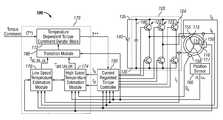
- FIG. 1illustrates a simplified block diagram of a three-phase electric motor system 100 architecture that may be implemented in a hybrid electric vehicle (HEV).
- the system 100includes a three-phase AC electric motor 110 , a three-phase pulse width modulated (PWM) inverter module 120 , a DC power source 140 , a current regulated torque controller 150 , a coolant temperature sensor 156 , a coolant flow rate sensor 158 , a rotor position sensor 160 , and a temperature estimation controller 170 .
- PWMpulse width modulated
- the system 100receives a torque command (T*) based on, for example, inputs from a driver.
- T*torque command
- the temperature estimation controller 170derates or limits the torque command (T*) based on the estimated temperature of the motor 110 to produce a derated torque command (T**).
- This derated torque command (T**)corresponds to the acceptable torque output of the motor 110 given the torque command (T*) and the current temperature of the motor 110 .
- the current regulated torque controller 150receives the derated torque command (T**) and, in response, controls the inverter module 120 to drive the motor 110 .
- the motor 110produces a torque on the drive shaft (not shown) of the HEV.
- the motor 110generally includes a stator with stator windings 115 , 116 , 117 that, when supplied with alternating current, produce a rotating magnetic field that causes a rotor (not shown) to rotate and generate torque.
- the three stator windings 115 , 116 , 117define a three-phase motor.
- the motor 110may be a permanent magnet synchronous motor, including an interior permanent magnet motor; an induction motor; a synchronous reluctance motor; or any other type of suitable electric motor.
- the inverter module 120drives the operation of the motor 110 .
- the inverter module 120generally includes a capacitor 180 and three inverter sub-modules 122 , 123 , 124 , each corresponding to a switching device respectively coupled to the stator windings 115 , 116 , 117 .
- Each switching device 122 , 123 , 124includes two switches (e.g., transistors such as Insulated Gate Bipolar Transistors (IGBTs)) that operate in an alternating manner with antiparallel diodes (not shown) to appropriately switch an input voltage and provide three-phase energization of the stator windings 115 , 116 , 117 of the motor 110 .
- IGBTsInsulated Gate Bipolar Transistors
- the inverter module 120is connected between direct current (DC) bus lines 135 of the DC power source 140 (e.g., one or more batteries or fuel cells) that supplies a DC input voltage (V DC ).
- DCdirect current
- the switching devices 122 , 123 , 124supply alternating current (Ia, Ib, Ic) to drive the three-phases corresponding to the stator windings 115 , 116 , 117 of the motor 110 at varying speeds based on the DC input voltage (V DC ) and control signals from the current regulated torque controller 150 . Additional details of the current regulated torque controller 150 may be found in U.S.
- the coolant temperature sensor 156determines the temperature of the coolant and provides a digital signal representation of the coolant temperature (T COOLANT ).
- the coolant flow rate sensor 158determines the flow rates (Q COOLANT ) of the coolant in the rotor and/or stator.
- the coolant temperature (T COOLANT ) and the coolant flow rates (Q COOLANT )are provided to the temperature estimation controller 170 for use in estimating the temperature of the stator windings 115 , 116 , 117 .
- the coolant flow rate (Q COOLANT )may be measured directly.
- the coolant flow rate(Q COOLANT ) may be derived as a function of the flow pressure, coolant and motor temperatures, motor torque, and motor speed.
- the coolant flow rate sensor 158may for a part of, or otherwise communicate with, a transmission control module and/or a hybrid control processor.
- the rotor position sensor 160is positioned to generate absolute angular position information and/or angular velocity information that correspond to the mechanical angle ( ⁇ r ) of the rotor and the angular velocity or speed ( ⁇ r ) of the rotor.
- the rotor position sensor 160may be implemented as a resolver and a resolver-to-digital converter, but can generally be any type of physical position sensor or transducer or virtual software implementation thereof, including a Hall Effect sensor or any other similar sensing device or encoder that senses the angular position or angular velocity of the rotor.
- the rotor position sensor 160provides the angular position ( ⁇ r ) and speed ( ⁇ r ) to the current regulated torque controller 150 and the temperature estimation controller 170 .
- the temperature estimation controller 170includes a temperature dependent torque command derater block 172 , a high speed temperature estimation module 174 , a low speed temperature estimation module 176 , and a transition module 180 .
- the high speed temperature estimation module 174receives synchronous frame currents (I d , I q ) from the current regulated torque controller 150 and estimates the phase temperatures (T aH , T bH , T cH ) of the stator windings 115 , 116 , 117 at high speeds.
- the estimated temperatures (T aH , T bH , T cH )are generated based on the synchronous frame currents (I d , I q ), rotor speed ( ⁇ r ), the DC voltage (V DC ), the coolant temperature (T COOLANT ), and the coolant flow rates (Q COOLANT ).
- the low speed temperature estimation module 176receives the detected current values (I a , I b , I c ) and estimates the phase temperatures (T aL , T bL , T cL ) of the stator windings 115 , 116 , 117 at low temperatures based on the current values (I a , I b , I c ) and the coolant temperature (T COOLANT ).
- the estimated phase temperatures (T aH , T bH , T cH ) from the high speed temperature estimation module 174 and the estimated phase temperatures (T aL , T bL , T cL ) from the low speed temperature estimation module 176are provided to the transition module 180 .
- the transition module 180provides one set of the estimated phase temperatures (T a , T b , T c ) to temperature dependent torque command derater block 172 .
- high speedscorrespond to rotor speeds ( ⁇ r ) greater than 75 rpm
- low speedscorrespond to rotor speeds ( ⁇ r ) less than 75 rpm, although the selection of the threshold between high and low speed may vary.
- the temperature dependent torque command derater block 172modifies the torque command (T*) in response to the selected set of phase temperatures (T a , T b , T c ) to generate a temperature derated torque command (T**).
- the current regulated torque controller 150controls the operation of the inverter module 120 , and thus the motor 110 , to produce the output torque based on the derated torque command (T**).
- the operational control signalsapply the gain represented by the temperature derated torque control signal (T**) to the command signals applied to the inverter module 120 .
- T**temperature derated torque control signal
- the currents at each of the stator windings 115 , 116 , 117are received and modified by the current regulated torque controller 150 in response to the temperature derated torque control signal (T**) to provide appropriate gain to the operational control signals while integrating a temperature dependent torque derating into the control structure at all speeds.
- Accurate estimation of the temperature of each stator winding 115 , 116 , 117may prevent overheating of the motor 110 while providing efficient operation.
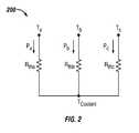
- FIG. 2is a circuit diagram representation of a thermal impedance model 200 in accordance with an exemplary embodiment.
- the thermal impedance model 200may be used by the high speed temperature estimation module 174 in accordance with an exemplary embodiment to determine the estimated winding temperatures (T aH , T bH , T cH ) at high speeds.
- the thermal impedance model 200is described more fully below with reference to Equations (4) through (6).
- the estimated winding temperatures (T aH , T bH , T cH )may be calculated based on a thermal impedance (R th ) between the stator windings 115 , 116 , 117 and coolant.
- the thermal impedance (R tha )is the thermal impedance between the temperature (T a ) of the first winding 115 and the coolant temperature of the motor coolant (T COOLANT )
- the thermal impedance (R thb )is the thermal impedance between the temperature (T b ) of the second winding 116 and the coolant temperature (T COOLANT )
- the thermal impedance (R tbc )is the thermal impedance between the temperature (T c ) of a third winding 117 and the coolant temperature (T COOLANT ).
- R DCis the DC resistance per phase
- i xis the stator current in a particular phase x
- N cis the number of coils in a series
- Nis the number of turns per coil
- l turnis the length of one turn
- a turnis the area of one turn
- ⁇ cuis the conductivity of copper
- P ironis the core (or iron) power loss
- P his the power dissipation due to hysteresis losses
- P eis the power dissipation due to eddy current losses
- B and B mare the peak flux density
- ⁇ , ⁇ h , and ⁇ eare constants for the particular core material
- fis the operating frequency of the motor
- f nis the fundamental nominal frequency of the motor.
- Equation (3)As shown in Equation (3), at low motor operating speeds, core losses (P iron ) are negligible since operating frequency (f) is a function of rotor speed ( ⁇ r ). However, at higher operating speeds, the operating frequency (f) increases and core losses (P iron ) become more significant. Accordingly, these core losses (P iron ) should be accounted for at high operating speeds to improve accuracy of the estimation.
- heat generated in the motor 110includes heat generated due to winding losses (P cu ) and core losses (P iron ) when using the high speed temperature estimation module 174 .
- the heat generated by windings losses (P cu )may be calculated using the stator currents and stator resistances described above with reference to Equation (2).
- the thermal impedance in each phaseincludes thermal impedance between the stator winding and the stator core and the thermal impedance between the stator core and the motor coolant.
- R thxis the thermal impedance between the stator winding and the motor coolant
- R wcxis the thermal impedance between the stator winding and stator core
- R ccxis the thermal impedance between the stator core and motor coolant
- the estimated temperature of the stator windings 115 , 116 , 117may be estimated using the thermal impedances (R tha , R thb , R thc ) and Equations (5), (6) and (7) as follows:
- T aR tha ⁇ ( 1 + T za ⁇ s 1 + 2 ⁇ ⁇ a ⁇ T wa ⁇ s + ( T wa ⁇ s ) 2 ) ⁇ ( I s 2 ⁇ R sa + P core ) + T coolant ( 5 )
- T bR thb ⁇ ( 1 + T zb ⁇ s 1 + 2 ⁇ ⁇ b ⁇ T wb ⁇ s + ( T wb ⁇ s ) 2 ) ⁇ ( I s 2 ⁇ R sb + P core ) + T coolant ( 6 )
- T cR thc ⁇ ( 1 + T zc ⁇ s 1 + 2 ⁇ ⁇ c ⁇ T wc ⁇ s + ( T wc ⁇ s ) 2 ) ⁇ ( I s 2 ⁇ R sc + P core ) + T coolant ( 7 )
- T zxis the lead time constant [seconds]
- T wxis the natural damped frequency [seconds]
- ⁇ xis the damping factor
- I sis the RMS stator current value [Amps] computed based on the synchronous reference frame current signals (I qs e , I ds e )
- R sxis the stator resistance [ ⁇ ]
- P coreis the stator core/iron loss [Watts]
- T COOLANTis the motor coolant temperature [°C.]
- xrepresents a, b, or c.
- stator currents(I a , I b , I c ) may not be the same because there will be instances in which only two phases are carrying current and the third phase has zero current flowing. As such, at low speeds, the actual stator currents may be used to compute stator winding losses. However, for high speed estimation, the stator currents (I a , I b , I c ) in all three phases should be the same. As such, stator winding power loss in each phase can be computed using the RMS value (I s ) of the motor currents.
- the thermal impedance model 200is represented in Equations (5), (6), and (7) by the combination of stator resistance (R thx ) and a 2 nd order transfer function model that is used to estimate the winding temperatures (T a , T b , T c ).
- the bracketed terms in Equations (5), (6) and (7)represent the total power loss (P x ) between the stator winding and the motor coolant due to the thermal impedance of each phase.
- the power loss (P x )takes into account the winding power loss (I s 2 R sx ) and the core power loss (P core ).
- the thermal impedancesmay be developed empirically offline from measured test data. This typically includes measuring phase currents, the temperature of each phase winding (e.g., with a thermistor or thermocouple), the coolant temperature (T COOLANT ) and the coolant flow rates (Q COOLANT ). This thermal model characterization may be performed using an instrumented motor, and the resulting model may be used for online temperature estimation with the same class of motor that does not have any temperature sensors directly on the stator windings.
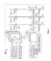
- FIG. 3is a block diagram of the high speed temperature estimation module 174 of the system 100 of FIG. 1 in accordance with an exemplary embodiment.
- the synchronous reference frame current signals (I d , I q )are received from the current regulated torque controller 150 ( FIG. 1 ) by a stator current square magnitude calculator 330 .
- the stator current square magnitude calculator 330uses the synchronous reference frame current signals (I d , I q ) to compute a squared RMS value (I s 2 ) of the stator current, which is then provided to the power loss calculators 332 , 334 , 336 .
- R sa , R sb , and R sc .are the stator winding resistances; T a , T b , T c are the estimated stator winding temperatures; R 25 designates the stator winding resistance at ambient temperature (25° C.); and ⁇ represents the temperature coefficient of resistance (typically 0.0039/° C. for copper winding).
- the power loss calculators 332 , 334 , 336use the estimated stator winding temperatures (T aL , T bL , T cL ) from the low speed stator phase temperature estimator 325 , discussed below, or the coolant temperature (T COOLANT ) to determine the stator winding resistances (R sa , R sb , R sc ).
- the power loss calculators 332 , 334 , 336use the previously estimated high speed stator winding temperature (T aH , T bH , T cH ) provided via a feedback loop to determine the stator winding resistances (R sa , R sb , R sc ).
- the power loss calculators 332 , 334 , 336then multiply the squared RMS value (I s 2 ) of the stator currents by the stator winding resistances (R sa , R sb , R sc ) to produce outputs representing stator winding power losses (P SWLA , P SWLB , P SWLC ), which are then provided to the high speed stator winding temperature estimator 348 .
- the input voltage (V DC ) of the DC voltage source, the temperature (T COOLANT ) of the coolant, the flow rate (Q COOLANT ) of the coolant, and the rotor speed ( ⁇ r )are provided as inputs to the high speed stator winding temperature estimator 348 .
- the high speed stator winding temperature estimator 348uses these inputs to estimate the high temperature stator winding temperatures (T aH , T bH , T cH ), as described in greater detail below with reference to FIG. 4 .
- FIG. 4illustrates a functional block diagram for describing the high speed stator winding temperature estimator 348 in accordance with an exemplary embodiment.
- the stator winding power losses (P SWLA , P SWLB , P SWLC ) for each phaseare calculated based the squared RMS stator current value (I s 2 ) and stator resistance value (R sa , R sb , R sc ).
- the stator winding power losses (P SWLA , P SWLB , P SWLC ) for each phaseare then added to the motor core loss (P core ), which is a function of the motor speed ( ⁇ r ), RMS stator winding current (I s ), and DC voltage (V DC ).
- a number of lookup tables (LUTs) 510 - 1 . . . 510 - n in the high speed stator winding temperature estimator 348may provide the motor core losses (P core ) at various DC voltages (V DC ), motor speeds ( ⁇ r ) and RMS currents (I s ). Interpolation (e.g., linear interpolation or other known interpolation techniques) may be used to further refine the resulting core losses (P core ) between LUT values.
- V DCDC voltages
- ⁇ rmotor speeds
- I sRMS currents
- the combination of the stator winding power losses (P SWLA , P SWLB , P SWLC ) and the core power losses (P core )result in total power losses (P a , P b , P c ).
- the total power losses (P a , P b , P c )represent the (I s 2 R sx +P core ) term of Equations (5), (6), and (7).
- the total power losses (P a , P b , P c )are subsequently provided as inputs to thermal impedance models 514 .
- the thermal impedance model 514determines the
- the thermal impedance model 514calculates the appropriate lead time constants (T za , T zb , T zc ), natural damped frequencies (T wa , T wb , T wc ), damping factors ( ⁇ a , ⁇ b , ⁇ c ), and thermal impedances (R tha , R thb , R thc ).
- the natural damped frequencies (T wa , T wb , T wc ), the damping factors ( ⁇ a , ⁇ b , ⁇ c ), and the thermal impedances (R tha , R thb , R thc )are each a function of the motor speed ( ⁇ r ) and/or the flow rates (Q COOLANT ) of the coolant.
- the natural damped frequencies (T wa , T wb , T wc )are a function of the flow rates (Q COOLANT ) of the coolant.
- the damping factors ( ⁇ a , ⁇ b , ⁇ c )are a function of the flow rates (Q COOLANT ) of the coolant.
- the thermal impedances (R tha , R thb , R thc )are a function of the motor speed ( ⁇ r ) and the flow rates (Q COOLANT ) of the coolant.
- the lead time constants (T za , T zb , T zc )may be a function of flow rates (Q COOLANT ).
- a number of lookup tables (LUTs) 512 - 1 . . . 512 - nare provided to provide the lead time constants (T za , T zb , T zc ), the natural damped frequencies (T wa , T wb , T wc ), the damping factors ( ⁇ a , ⁇ b , ⁇ c ), and the thermal impedances (R tha , R thb , R thc ) based on the inputs of the motor speed ( ⁇ r ) and the coolant flow rates (Q COOLANT ).
- interpolationmay be used to further refine the resulting LUT values. These values may be developed empirically off-line from measured test data. This generally involves various measurements over a number of motor speed ( ⁇ r ) and the flow rates (Q COOLANT ) in an instrumented motor to provide thermal models that may be used for temperature estimation without winding temperature sensors.
- the thermal impedance models 514calculate a change in temperature ( ⁇ T an , ⁇ T bn , ⁇ T cn ) for each phase.
- the change in temperature ( ⁇ T an , ⁇ T bn , ⁇ T cn )is then added to the motor coolant temperature (T COOLANT ) to obtain the high speed estimated stator winding temperature (T aH , T bH , T cH ) for each phase.
- FIG. 5is a block diagram of the low speed temperature estimation module 176 of the system 100 of FIG. 1 in accordance with an exemplary embodiment.
- stator currentsI a , I b , I c
- combiners 302 , 304 , 306that generate waveforms equivalent to the AC RMS currents (I a 2 , I b 2 , I c 2 ) for each of the stator windings 115 , 116 , 117 .
- These waveformsare provided to blocks 308 , 310 and 312 , respectively.
- Blocks 308 , 310 , 312respectively calculate the stator phase resistance (R sa , R sb , R sc ) for each phase in response to a feedback low speed estimated temperature (T aL , T bL , T cL ), similar to the description above with reference to Equations (8), (9), and (10), and multiply the stator phase resistance (R sa , R sb , R sc ) with the AC RMS currents (I a 2 , I b 2 , I c 2 ) from the output of the combiners 302 , 304 , 306 .
- the resulting productsare provided to blocks 314 , 316 , 318 for calculation of the temperature rise ( ⁇ T an , ⁇ T bn , ⁇ T cn ) due to the thermal impedance (Z ⁇ — an , Z ⁇ — bn , Z ⁇ — cn ).
- Outputs of blocks 308 , 310 , 312are also provided to block 320 for calculation of the temperature rise ( ⁇ T nc ) due to the thermal impedance (Z ⁇ — nc ) between the thermal neutral and the coolant.
- the outputs of blocks 314 , 316 , 318 , 320 , as well coolant temperature (T COOLANT ),are provided as inputs to a low speed stator phase temperature estimator 325 for estimation of the low speed temperature estimates (T aL , T bL , T cL ).
- the low speed temperature estimates(T aL , T bL , T cL ) are used by the transition module 180 to determine the appropriate temperature estimates (T a , T b , T c ). Additional techniques for estimating stator temperature at low speeds are described in United States Patent Application Publication Number 2009/0189561 A1, filed Jan. 24, 2008 and assigned to the assignee of the present invention, which is incorporated by reference herein in its entirety.
- FIGS. 1-5depict the temperature estimation controller 170 including identifiable modules and blocks, it will be appreciated that these blocks or modules may be implemented as software modules that execute on a microprocessor, and therefore operation of the temperature estimation controller 170 may alternately be represented as steps of a method, as will now be described with reference to FIG. 6 .
- FIG. 6illustrates a flowchart of a method 600 for the operation of a temperature estimation controller 170 of the system 100 of FIG. 1 in accordance with an exemplary embodiment.
- FIG. 1is referenced in the description below.
- Processingbegins when the motor 110 is turned on at step 602 .
- an alternating current (AC) root mean square (RMS) current valueis calculated 604 .
- the copper loss of each of the stator windings 115 , 116 , 117 of the motor 110is then calculated at step 606 , and first thermal impedances for each of the stator windings 115 , 116 , 117 of the motor 110 are calculated at step 608 in response to the copper loss calculated at step 606 .
- step 610temperature increases in the stator windings 115 , 116 , 117 due to corresponding thermal impedances are determined.
- step 612the temperature of the coolant is determined, for example, by the coolant temperature sensor 156 .
- step 614the temperature increases due to the thermal impedance of the thermal neutral with respect to the temperature of the coolant is determined, and at step 616 , low speed stator winding temperatures are estimated for each phase based on results generated at steps, 610 , 612 , and 614 .
- processingdetermines whether the speed of the motor 110 is greater than a threshold speed (e.g., 75 rpms). When the speed is less than the threshold speed, at step 620 the stator winding temperatures are set equal to the estimated low speed stator temperatures from step 616 . The torque command is then derated at step 622 to prevent overheating of one or more of the stator windings 115 , 116 , 117 . Processing then returns to step 602 .
- a threshold speede.g. 75 rpms
- step 624When the speed is determined to be greater than or equal to the threshold speed at step 618 , processing proceeds to step 624 .
- the high speed stator winding temperaturesare estimated.
- stator winding resistances of the stator windings 115 , 116 , 117are determined.
- the stator winding resistancesmay be estimated, for example, using the estimated stator winding temperatures from the low speed stator phase temperature estimator.
- the stator winding resistancesmay be estimated, for example, using the previously estimated high speed stator winding temperatures.
- processingdetermines stator winding power losses based on stator winding resistances and the RMS stator currents.
- processingdetermines total power loss in each phase based on stator winding power losses and core power losses.
- processingestimates a stator winding temperature for each phase based on total power losses, motor speed, coolant temperature, and coolant flow rate. For reference, one exemplary implementation of steps 628 and 630 are described above with reference to FIG. 4 .
- the stator winding temperaturesare set equal to the high speed estimated stator winding temperatures.
- the estimated stator winding temperatures computed at step 632are provided to the derater block 172 and used to derate the torque command. The method 600 then loops back to step 602 .
- exemplary embodiments discussed aboveprovide systems and methods for estimating the stator winding temperatures without requiring a temperature sensor directly on the stator winding.
- the estimation systems and methodsaccurately estimate stator winding temperatures over low speed and high speeds.
- the systems and methodsestimate the high speed stator winding temperatures as a function of motor speed and coolant flow rates for a more accurate estimation.
- the disclosed embodimentsmay be applied to a permanent magnet synchronous AC motor (PMSM), such as an Interior Permanent Magnet Synchronous Motor (IPMSM) and a Surface Mount Permanent Magnet Synchronous Motor (SMPMSM).
- PMSMpermanent magnet synchronous AC motor
- IPMSMInterior Permanent Magnet Synchronous Motor
- SMPMSMSurface Mount Permanent Magnet Synchronous Motor
- an AC machinecan be an AC motor (i.e., apparatus used to convert AC electrical energy power at its input to produce to mechanical energy or power)
- an AC machineis not limited to being an AC motor, but can also encompass generators that are used to convert mechanical energy or power into electrical AC energy or power.
- the disclosed embodimentscan be implemented in operating environments such as a hybrid electric vehicle (HEV), it will be appreciated by those skilled in the art that the same or similar techniques and technologies can be applied in the context of other systems. In this regard, any of the concepts disclosed here can be applied generally to vehicles.
- HEVhybrid electric vehicle
- vehiclesexamples include automobiles such as buses, cars, trucks, sport utility vehicles, vans, vehicles that do not travel on land such as mechanical water vehicles including watercraft, hovercraft, sailcraft, boats and ships, mechanical under water vehicles including submarines, mechanical air vehicles including aircraft and spacecraft, mechanical rail vehicles such as trains, trams and trolleys, etc.
- vehicleis not limited by any specific propulsion technology such as gasoline or diesel fuel. Rather, vehicles also include hybrid vehicles, battery electric vehicles, hydrogen vehicles, and vehicles which operate using various other alternative fuels.
- a software modulemay reside in RAM memory, flash memory, ROM memory, EPROM memory, EEPROM memory, registers, hard disk, a removable disk, a CD-ROM, or any other form of storage medium known in the art.
- An exemplary storage mediumis coupled to the processor such the processor can read information from, and write information to, the storage medium.
- the storage mediummay be integral to the processor.
- the processor and the storage mediummay reside in an ASIC.
Landscapes
- Engineering & Computer Science (AREA)
- Power Engineering (AREA)
- Physics & Mathematics (AREA)
- General Physics & Mathematics (AREA)
- Microelectronics & Electronic Packaging (AREA)
- Control Of Ac Motors In General (AREA)
- Control Of Electric Motors In General (AREA)
Abstract
Description
Temperature Change=Thermal Impedance*Total Power Dissipation (1)
For example, the temperature difference (ΔTx) between the temperature (Tx) of the stator winding and coolant temperature (TCOOLANT) is equal to the product of the thermal impedance (Rthx) and power dissipation (Px) for a particular phase. The
Rthx=Rwcx+Rccx (4)
Rsa=R25(1+α(Ta−25)) (8)
Rsb=R25(1+α(Tb−25)) (9)
Rsc=R25(1+α(Tc−25)) 10)
term Equations (5), (6), and (7). In particular, the
Claims (20)
Priority Applications (3)
| Application Number | Priority Date | Filing Date | Title |
|---|---|---|---|
| US12/778,733US8421391B2 (en) | 2010-05-12 | 2010-05-12 | Electric motor stator winding temperature estimation systems and methods |
| DE102011075605.1ADE102011075605B4 (en) | 2010-05-12 | 2011-05-10 | Electric motor stator winding temperature estimation systems |
| CN201110122349.9ACN102255435B (en) | 2010-05-12 | 2011-05-12 | Electric motor stator winding temperature estimation systems and methods |
Applications Claiming Priority (1)
| Application Number | Priority Date | Filing Date | Title |
|---|---|---|---|
| US12/778,733US8421391B2 (en) | 2010-05-12 | 2010-05-12 | Electric motor stator winding temperature estimation systems and methods |
Publications (2)
| Publication Number | Publication Date |
|---|---|
| US20110279074A1 US20110279074A1 (en) | 2011-11-17 |
| US8421391B2true US8421391B2 (en) | 2013-04-16 |
Family
ID=44911179
Family Applications (1)
| Application Number | Title | Priority Date | Filing Date |
|---|---|---|---|
| US12/778,733Expired - Fee RelatedUS8421391B2 (en) | 2010-05-12 | 2010-05-12 | Electric motor stator winding temperature estimation systems and methods |
Country Status (3)
| Country | Link |
|---|---|
| US (1) | US8421391B2 (en) |
| CN (1) | CN102255435B (en) |
| DE (1) | DE102011075605B4 (en) |
Cited By (15)
| Publication number | Priority date | Publication date | Assignee | Title |
|---|---|---|---|---|
| US20120242272A1 (en)* | 2011-03-23 | 2012-09-27 | Toyota Jidosha Kabushiki Kaisha | Rotating electrical machine system |
| US20120326650A1 (en)* | 2011-06-24 | 2012-12-27 | Honda Motor Co., Ltd. | Rotating electrical machine control apparatus |
| US20140125268A1 (en)* | 2010-12-02 | 2014-05-08 | Mercedes Herranz Gracia | Method and device for operating an electrical machine having separate excitation |
| US20150155802A1 (en)* | 2012-09-11 | 2015-06-04 | Toyota Jidosha Kabushiki Kaisha | Control Device for Rotating Electrical Machine, and Rotating Electrical Machine Drive System Including Control Device |
| US20160065112A1 (en)* | 2014-08-29 | 2016-03-03 | General Electric Company | Magnet management in electric machines |
| US20160359445A1 (en)* | 2014-02-17 | 2016-12-08 | Kevin Lee | Control and protection apparatus for electric motor |
| US20170077848A1 (en)* | 2015-09-15 | 2017-03-16 | GM Global Technology Operations LLC | Method and apparatus for a position sensor for a transmission integrated synchronous motor |
| US20170141716A1 (en)* | 2015-11-13 | 2017-05-18 | Denso Corporation | Rotary electric machine control apparatus |
| US9698660B2 (en) | 2013-10-25 | 2017-07-04 | General Electric Company | System and method for heating ferrite magnet motors for low temperatures |
| US20170214358A1 (en)* | 2014-09-11 | 2017-07-27 | Panasonic Intellectual Property Management Co., Ltd. | Brushless motor and washing machine provided with same |
| US10411566B2 (en)* | 2016-04-20 | 2019-09-10 | Toyota Jidosha Kabushiki Kaisha | Motor temperature estimating device |
| US11114968B2 (en)* | 2017-11-24 | 2021-09-07 | Mitsubishi Electric Corporation | Rotating electric machine device and rotating electric machine device control method |
| US11408839B2 (en)* | 2018-07-03 | 2022-08-09 | Omron Corporation | Processing device |
| US11652428B2 (en) | 2021-07-14 | 2023-05-16 | General Electric Company | Method and apparatus for controlling a motor |
| US12068641B2 (en) | 2022-06-15 | 2024-08-20 | Livewire Ev, Llc | Motor hotspot identification |
Families Citing this family (51)
| Publication number | Priority date | Publication date | Assignee | Title |
|---|---|---|---|---|
| KR101261946B1 (en)* | 2010-12-02 | 2013-05-09 | 현대자동차주식회사 | Cooling system for cooling driving motor of hybrid vehicle and method for controlling the same |
| US9166518B2 (en)* | 2011-06-27 | 2015-10-20 | GM Global Technology Operations LLC | Rotor temperature estimation for an electric vehicle |
| JP5149431B2 (en)* | 2011-07-29 | 2013-02-20 | ファナック株式会社 | Temperature detection device that detects the temperature of the mover of the motor |
| DE102011121272A1 (en) | 2011-12-15 | 2013-06-20 | Audi Ag | Method and device for temperature-dependent control of an electric motor |
| CN102545764A (en)* | 2012-01-04 | 2012-07-04 | 郑州飞机装备有限责任公司 | Pure electric vehicle driving motor stator resistance real-time on-line compensation method |
| CN102522930A (en)* | 2012-01-04 | 2012-06-27 | 郑州飞机装备有限责任公司 | Torque control method for motor of pure electric vehicle |
| US9490682B2 (en) | 2012-06-01 | 2016-11-08 | General Electric Company | Method and system for alternator thermal protection |
| US9018878B2 (en)* | 2012-07-23 | 2015-04-28 | Caterpillar Inc. | Derating vehicle electric drive motor and generator components |
| JP5607698B2 (en)* | 2012-10-18 | 2014-10-15 | ファナック株式会社 | Temperature estimation device for estimating the temperature of an electric motor |
| US10161660B2 (en)* | 2012-10-19 | 2018-12-25 | Obshchestvo S Ogranichennoy Otvetstvennostyu “Kompaniya Rmt” | Measurement path of a temperature controller for a thermoelectric module |
| FR3001343B1 (en)* | 2013-01-18 | 2015-03-13 | Thales Sa | MODULAR BAY OF INVERTERS AND ITS CONTROL METHOD FOR A SET OF ELECTRIC MACHINES HAVING POSITION SENSORS |
| JP5667242B2 (en)* | 2013-06-10 | 2015-02-12 | ファナック株式会社 | Temperature estimation device for estimating temperature of power semiconductor chip and motor control device including the same |
| ES2439633A1 (en)* | 2013-07-23 | 2014-01-23 | Universidad Politécnica de Madrid | Protection method and system for electric motors with increased safety induction by measuring rotor speed |
| JP5900434B2 (en)* | 2013-08-09 | 2016-04-06 | トヨタ自動車株式会社 | Rotating electrical machine temperature estimation system for vehicles |
| EP2894782B1 (en)* | 2014-01-13 | 2018-08-29 | Nissan Motor Co., Ltd. | Torque estimating system for synchronous electric motor |
| JP5877860B2 (en)* | 2014-03-12 | 2016-03-08 | ファナック株式会社 | Temperature detector for motor mover and overheat protection device for motor |
| KR101542994B1 (en)* | 2014-04-14 | 2015-08-07 | 현대자동차 주식회사 | Method of estimating temperature of rotor of motor |
| CN104864980B (en)* | 2014-05-19 | 2019-03-12 | 北京宝沃汽车有限公司 | A kind of motor stator temperature detection device and method, device for monitoring temperature and method |
| CN106464194B (en)* | 2014-06-27 | 2019-06-18 | 本田技研工业株式会社 | Winding temperature estimation device for rotating electrical machine and method for estimating winding temperature of rotating electrical machine |
| US9242576B1 (en)* | 2014-07-25 | 2016-01-26 | GM Global Technology Operations LLC | Method and apparatus for controlling an electric machine |
| US9444389B2 (en)* | 2015-01-29 | 2016-09-13 | GM Global Technology Operations LLC | Derating control of a power inverter module |
| KR101856431B1 (en)* | 2015-03-30 | 2018-05-09 | 미쓰비시덴키 가부시키가이샤 | Protective Devices and Servo Motors |
| JP6427805B2 (en)* | 2015-05-19 | 2018-11-28 | 本田技研工業株式会社 | Temperature estimation device for rotating electrical machines |
| US9496817B1 (en)* | 2015-06-21 | 2016-11-15 | Freescale Semiconductor, Inc. | Electric motor thermal management |
| JP6402701B2 (en)* | 2015-10-29 | 2018-10-10 | トヨタ自動車株式会社 | Motor temperature estimation device |
| US9762146B2 (en)* | 2015-10-30 | 2017-09-12 | Faraday&Future Inc. | Methods and systems for interconnecting parallel IGBT modules |
| US9647602B1 (en)* | 2015-11-04 | 2017-05-09 | GM Global Technology Operations LLC | Determination of stator winding resistance in an electric machine |
| JP6360032B2 (en)* | 2015-12-24 | 2018-07-18 | ファナック株式会社 | Machine tool control device having function of changing operation according to motor temperature and amplifier temperature |
| CN105844030B (en)* | 2016-03-29 | 2018-12-11 | 中国第一汽车股份有限公司 | A kind of permanent-magnetic synchronous motor rotor temperature online evaluation method |
| US10556485B2 (en) | 2016-05-31 | 2020-02-11 | Ge Global Sourcing Llc | Systems and methods for blower control |
| JP6638637B2 (en)* | 2016-12-14 | 2020-01-29 | トヨタ自動車株式会社 | Temperature estimation system for rotating electric machines |
| KR102290819B1 (en)* | 2017-02-27 | 2021-08-17 | 도시바 미쓰비시덴키 산교시스템 가부시키가이샤 | controller |
| DE102017212191A1 (en)* | 2017-07-17 | 2019-01-17 | Audi Ag | heater |
| FR3073685B1 (en)* | 2017-11-16 | 2022-05-27 | Valeo Equip Electr Moteur | ELECTRIC MACHINE FOR A MOTOR VEHICLE COMPRISING A TEMPERATURE ESTIMATOR |
| US10965240B2 (en) | 2018-08-30 | 2021-03-30 | Texas Instruments Incorporated | Method and circuit for detecting motor winding over temperature |
| DE102018130495A1 (en)* | 2018-11-30 | 2020-06-04 | Schaeffler Technologies AG & Co. KG | Procedure for the current condition monitoring of an electric motor |
| EP3672007A1 (en)* | 2018-12-17 | 2020-06-24 | Siemens Aktiengesellschaft | Determination of the flow speed in a coolant circuit |
| US10700632B1 (en)* | 2019-01-11 | 2020-06-30 | GM Global Technology Operations LLC | Method for motor and inverter temperature control |
| CN110474574B (en)* | 2019-09-19 | 2021-05-25 | 上海元城汽车技术有限公司 | Control method and device of permanent magnet synchronous motor and motor controller |
| JP7388158B2 (en)* | 2019-11-29 | 2023-11-29 | オムロン株式会社 | Processing device and method for determining winding temperature calculation model |
| CN111277200B (en)* | 2020-02-12 | 2021-10-22 | 杭州电子科技大学 | A kind of motor winding temperature estimation and protection method |
| US11804799B2 (en)* | 2020-03-31 | 2023-10-31 | Steering Solutions Ip Holding Corporation | Detection of unbalanced phase resistances in synchronous motor drives |
| EP3952102B1 (en)* | 2020-08-06 | 2025-03-05 | Siemens Aktiengesellschaft | Overload-proof motor control |
| MX2022001398A (en)* | 2021-05-17 | 2023-01-24 | Nissan Motor | METHOD TO CONTROL ENGINE, DEVICE TO CONTROL ENGINE. |
| US12091027B2 (en)* | 2021-07-15 | 2024-09-17 | Fca Us Llc | Vehicle electric motor temperature estimation using neural network model |
| CN115771394A (en)* | 2021-09-07 | 2023-03-10 | 本田技研工业株式会社 | Vehicle with a steering wheel |
| WO2023099485A1 (en)* | 2021-11-30 | 2023-06-08 | Robert Bosch Gmbh | Method for monitoring a drive unit of a vehicle |
| EP4441885A1 (en)* | 2021-11-30 | 2024-10-09 | Robert Bosch GmbH | Method for monitoring a drive unit of a vehicle |
| CN116238306B (en)* | 2021-12-08 | 2025-09-05 | 纬湃汽车电子(天津)有限公司 | All-in-one power system and temperature estimation method thereof |
| CN115219055A (en)* | 2022-07-28 | 2022-10-21 | 中国商用飞机有限责任公司北京民用飞机技术研究中心 | Internal temperature prediction method and system for aviation three-stage generator |
| US12296693B2 (en) | 2023-07-12 | 2025-05-13 | GM Global Technology Operations LLC | System and method for temperature estimation of inverter AC power bus |
Citations (20)
| Publication number | Priority date | Publication date | Assignee | Title |
|---|---|---|---|---|
| US4958116A (en) | 1984-06-18 | 1990-09-18 | Mitsubishi Denki Kabushiki Kaisha | Method for controlling AC induction motor |
| US5043649A (en) | 1988-12-28 | 1991-08-27 | Nippondenso Co., Ltd. | Stepping motor unit and rotary control valve incorporating the same |
| US5144216A (en) | 1991-10-02 | 1992-09-01 | General Electric Company | High speed flux feedback for tuning a universal field oriented controller capable of operating in direct and indirect field orientation modes |
| US5334923A (en) | 1990-10-01 | 1994-08-02 | Wisconsin Alumni Research Foundation | Motor torque control method and apparatus |
| US5936820A (en) | 1997-05-30 | 1999-08-10 | Aisin Seiki Co., Ltd. | Overheating protection system of switching module |
| US6433506B1 (en) | 2001-03-29 | 2002-08-13 | Ford Global Technologies, Inc. | Sensorless control system for induction motor employing direct torque and flux regulation |
| US6683428B2 (en) | 2002-01-30 | 2004-01-27 | Ford Global Technologies, Llc | Method for controlling torque in a rotational sensorless induction motor control system with speed and rotor flux estimation |
| US6854881B2 (en) | 2000-05-09 | 2005-02-15 | Toyota Jidosha Kabushiki Kaisha | Method of estimating temperature and device for the effecting same |
| US6870348B2 (en) | 2003-08-06 | 2005-03-22 | General Motors Corporation | Rotor resistance adaptation for indirect field oriented control of induction machine |
| CN101261162A (en) | 2008-04-29 | 2008-09-10 | 重庆长安汽车股份有限公司 | Hybrid power automobile start-up energy production integrated electric motor temperature field measuring systems |
| US20090066283A1 (en) | 2006-09-08 | 2009-03-12 | Gm Global Technology Operations, Inc. | Method and system for limiting the operating temperature of an electric motor |
| US7560895B2 (en) | 2007-03-16 | 2009-07-14 | Azure Dynamics, Inc. | Indirect rotor resistance estimation system and method |
| CN201281637Y (en) | 2008-04-29 | 2009-07-29 | 重庆长安汽车股份有限公司 | System for measuring temperature field of startup and electrification integrated motor |
| US20090189561A1 (en) | 2008-01-24 | 2009-07-30 | Gm Global Technology Operations, Inc. | Electric motor stator winding temperature estimation |
| US7570074B2 (en) | 2005-05-09 | 2009-08-04 | Square D Company | Electronic overload relay for mains-fed induction motors |
| US7746013B2 (en) | 2005-06-08 | 2010-06-29 | Siemens Vdo Automotive Ag | Method and device for controlling a brushless direct-current motor |
| US20100236502A1 (en)* | 2007-11-21 | 2010-09-23 | Toyota Jidosha Kabushiki Kaisha | Vehicle cooling controller and cooling control method |
| US20110050141A1 (en) | 2009-08-31 | 2011-03-03 | Gm Global Technology Operations, Inc. | Electric motor stator winding temperature estimation |
| US8013565B2 (en) | 2007-03-29 | 2011-09-06 | Toyota Jidosha Kabushiki Kaisha | Motor control device, control method, and control program |
| US8384338B2 (en) | 2009-01-30 | 2013-02-26 | Eaton Corporation | System and method for determining stator winding resistance in an AC motor using motor drives |
Family Cites Families (1)
| Publication number | Priority date | Publication date | Assignee | Title |
|---|---|---|---|---|
| JP4410078B2 (en)* | 2004-10-13 | 2010-02-03 | 本田技研工業株式会社 | Electric motor overheat prevention device |
- 2010
- 2010-05-12USUS12/778,733patent/US8421391B2/ennot_activeExpired - Fee Related
- 2011
- 2011-05-10DEDE102011075605.1Apatent/DE102011075605B4/ennot_activeExpired - Fee Related
- 2011-05-12CNCN201110122349.9Apatent/CN102255435B/ennot_activeExpired - Fee Related
Patent Citations (21)
| Publication number | Priority date | Publication date | Assignee | Title |
|---|---|---|---|---|
| US4958116A (en) | 1984-06-18 | 1990-09-18 | Mitsubishi Denki Kabushiki Kaisha | Method for controlling AC induction motor |
| US5043649A (en) | 1988-12-28 | 1991-08-27 | Nippondenso Co., Ltd. | Stepping motor unit and rotary control valve incorporating the same |
| US5334923A (en) | 1990-10-01 | 1994-08-02 | Wisconsin Alumni Research Foundation | Motor torque control method and apparatus |
| US5144216A (en) | 1991-10-02 | 1992-09-01 | General Electric Company | High speed flux feedback for tuning a universal field oriented controller capable of operating in direct and indirect field orientation modes |
| US5936820A (en) | 1997-05-30 | 1999-08-10 | Aisin Seiki Co., Ltd. | Overheating protection system of switching module |
| US6854881B2 (en) | 2000-05-09 | 2005-02-15 | Toyota Jidosha Kabushiki Kaisha | Method of estimating temperature and device for the effecting same |
| US6433506B1 (en) | 2001-03-29 | 2002-08-13 | Ford Global Technologies, Inc. | Sensorless control system for induction motor employing direct torque and flux regulation |
| US6683428B2 (en) | 2002-01-30 | 2004-01-27 | Ford Global Technologies, Llc | Method for controlling torque in a rotational sensorless induction motor control system with speed and rotor flux estimation |
| US6870348B2 (en) | 2003-08-06 | 2005-03-22 | General Motors Corporation | Rotor resistance adaptation for indirect field oriented control of induction machine |
| US7570074B2 (en) | 2005-05-09 | 2009-08-04 | Square D Company | Electronic overload relay for mains-fed induction motors |
| US7746013B2 (en) | 2005-06-08 | 2010-06-29 | Siemens Vdo Automotive Ag | Method and device for controlling a brushless direct-current motor |
| US20090066283A1 (en) | 2006-09-08 | 2009-03-12 | Gm Global Technology Operations, Inc. | Method and system for limiting the operating temperature of an electric motor |
| US7615951B2 (en) | 2006-09-08 | 2009-11-10 | Gm Global Technology Operations, Inc. | Method and system for limiting the operating temperature of an electric motor |
| US7560895B2 (en) | 2007-03-16 | 2009-07-14 | Azure Dynamics, Inc. | Indirect rotor resistance estimation system and method |
| US8013565B2 (en) | 2007-03-29 | 2011-09-06 | Toyota Jidosha Kabushiki Kaisha | Motor control device, control method, and control program |
| US20100236502A1 (en)* | 2007-11-21 | 2010-09-23 | Toyota Jidosha Kabushiki Kaisha | Vehicle cooling controller and cooling control method |
| US20090189561A1 (en) | 2008-01-24 | 2009-07-30 | Gm Global Technology Operations, Inc. | Electric motor stator winding temperature estimation |
| CN201281637Y (en) | 2008-04-29 | 2009-07-29 | 重庆长安汽车股份有限公司 | System for measuring temperature field of startup and electrification integrated motor |
| CN101261162A (en) | 2008-04-29 | 2008-09-10 | 重庆长安汽车股份有限公司 | Hybrid power automobile start-up energy production integrated electric motor temperature field measuring systems |
| US8384338B2 (en) | 2009-01-30 | 2013-02-26 | Eaton Corporation | System and method for determining stator winding resistance in an AC motor using motor drives |
| US20110050141A1 (en) | 2009-08-31 | 2011-03-03 | Gm Global Technology Operations, Inc. | Electric motor stator winding temperature estimation |
Non-Patent Citations (15)
| Title |
|---|
| Al-Tayie, J.K., et al. "Estimation of speed, stator temperature and rotor temperature in cage induction motor drive using the extended kalman filter algorithm," IEEE Proceedings in Electric Power Applications, Sep. 1997, pp. 301-309, vol. 144, No. 5. |
| Asaii, B., et al. "A new thermal model for EV induction machine drives," IEEE Power Electronics in Transportation, Oct. 1996, pp. 175-182. |
| Briz, F., et al. "Temperature estimation in inverter-fed machines using high-frequency carrier signal injection," IEEE Transactions on Industry Applications, May/Jun. 2008, pp. 799-808, vol. 44, No. 3. |
| Campbell, M., et al. "Methods and Systems for Induction Machine Control," U.S. Appl. No. 12/635,313, filed Dec. 10, 2009. |
| Chinese Patent & Trademark Office. Chinese Office Action dated Dec. 21, 2012 for Application No. 201010269361.8. |
| Chinese Patent & Trademark Office. Chinese Office Action dated Jan. 30, 2013 for Application No. 201110122349.9. |
| Colby, R.S., et al. "A model reduction perspective on thermal models for induction machine overload relays," IEEE Transactions on Industrial Electronics, Oct. 2008, pp. 3525-3534, vol. 55, No. 10. |
| Gao, Z., et al. "A sensorless adaptive stator winding temperature estimator for mains-fed induction machines with continuous-operation periodic duty cycles," IEEE Transactions on Industry Applications, Sep./Oct. 2008, pp. 1533-1542, vol. 44, No. 5. |
| Mellor, P.H., et al. "Lumped parameter thermal model for electrical machines of TEFC design," IEEE Proceedings on Electric Power Applications, Sep. 1991, pp. 205-218, vol. 138, No. 5. |
| U.S. Notice of Allowance, dated Aug. 8, 2012, for U.S. Appl. No. 12/784,873. |
| U.S. Notice of Allowance, dated Feb. 26, 2013, for U.S. Appl. No. 12/568,002. |
| U.S. Office Action, dated Aug. 16, 2012, for U.S. Appl. No. 12/568,002. |
| U.S. Office Action, dated Aug. 9, 2012, for U.S. Appl. No. 12/635,313. |
| United States Patent and Trademark Office, U.S. Office Action dated Mar. 28, 2012 for U.S. Appl. No. 12/568,002. |
| Yeh, C-C., et al. "Electric Motor Stator Winding Temperature Estimation," U.S. Appl. No. 12/568,002, filed Sep. 28, 2009. |
Cited By (24)
| Publication number | Priority date | Publication date | Assignee | Title |
|---|---|---|---|---|
| US20140125268A1 (en)* | 2010-12-02 | 2014-05-08 | Mercedes Herranz Gracia | Method and device for operating an electrical machine having separate excitation |
| US9531304B2 (en)* | 2010-12-02 | 2016-12-27 | Robert Bosch Gmbh | Method and device for operating an electrical machine having separate excitation |
| US8680801B2 (en)* | 2011-03-23 | 2014-03-25 | Toyota Jidosha Kabushiki Kaisha | Rotating electrical machine system |
| US20120242272A1 (en)* | 2011-03-23 | 2012-09-27 | Toyota Jidosha Kabushiki Kaisha | Rotating electrical machine system |
| US20120326650A1 (en)* | 2011-06-24 | 2012-12-27 | Honda Motor Co., Ltd. | Rotating electrical machine control apparatus |
| US9065373B2 (en)* | 2011-06-24 | 2015-06-23 | Honda Motor Co., Ltd. | Rotating electrical machine control apparatus |
| US20150155802A1 (en)* | 2012-09-11 | 2015-06-04 | Toyota Jidosha Kabushiki Kaisha | Control Device for Rotating Electrical Machine, and Rotating Electrical Machine Drive System Including Control Device |
| US9698660B2 (en) | 2013-10-25 | 2017-07-04 | General Electric Company | System and method for heating ferrite magnet motors for low temperatures |
| US9966897B2 (en) | 2013-10-25 | 2018-05-08 | General Electric Company | System and method for heating ferrite magnet motors for low temperatures |
| US20160359445A1 (en)* | 2014-02-17 | 2016-12-08 | Kevin Lee | Control and protection apparatus for electric motor |
| US9876461B2 (en)* | 2014-02-17 | 2018-01-23 | Eaton Corporation | Control and protection apparatus for electric motor |
| US20160065112A1 (en)* | 2014-08-29 | 2016-03-03 | General Electric Company | Magnet management in electric machines |
| US9602043B2 (en)* | 2014-08-29 | 2017-03-21 | General Electric Company | Magnet management in electric machines |
| US20170214358A1 (en)* | 2014-09-11 | 2017-07-27 | Panasonic Intellectual Property Management Co., Ltd. | Brushless motor and washing machine provided with same |
| US9973138B2 (en)* | 2014-09-11 | 2018-05-15 | Panasonic Intellectual Property Management Co., Ltd. | Brushless motor and washing machine provided with same |
| US9866157B2 (en)* | 2015-09-15 | 2018-01-09 | GM Global Technology Operations LLC | Method and apparatus for a position sensor for a transmission integrated synchronous motor |
| US20170077848A1 (en)* | 2015-09-15 | 2017-03-16 | GM Global Technology Operations LLC | Method and apparatus for a position sensor for a transmission integrated synchronous motor |
| US20170141716A1 (en)* | 2015-11-13 | 2017-05-18 | Denso Corporation | Rotary electric machine control apparatus |
| US9806663B2 (en)* | 2015-11-13 | 2017-10-31 | Denso Corporation | Rotary electric machine control apparatus |
| US10411566B2 (en)* | 2016-04-20 | 2019-09-10 | Toyota Jidosha Kabushiki Kaisha | Motor temperature estimating device |
| US11114968B2 (en)* | 2017-11-24 | 2021-09-07 | Mitsubishi Electric Corporation | Rotating electric machine device and rotating electric machine device control method |
| US11408839B2 (en)* | 2018-07-03 | 2022-08-09 | Omron Corporation | Processing device |
| US11652428B2 (en) | 2021-07-14 | 2023-05-16 | General Electric Company | Method and apparatus for controlling a motor |
| US12068641B2 (en) | 2022-06-15 | 2024-08-20 | Livewire Ev, Llc | Motor hotspot identification |
Also Published As
| Publication number | Publication date |
|---|---|
| DE102011075605B4 (en) | 2019-11-14 |
| DE102011075605A1 (en) | 2012-03-15 |
| CN102255435A (en) | 2011-11-23 |
| CN102255435B (en) | 2014-03-12 |
| US20110279074A1 (en) | 2011-11-17 |
Similar Documents
| Publication | Publication Date | Title |
|---|---|---|
| US8421391B2 (en) | Electric motor stator winding temperature estimation systems and methods | |
| US8487575B2 (en) | Electric motor stator winding temperature estimation | |
| US8339082B2 (en) | Methods and systems for induction motor control | |
| US7839108B2 (en) | Electric motor stator winding temperature estimation | |
| CN103931096B (en) | Method and system with function of temperature compensation control motor | |
| Jung et al. | Non-invasive magnet temperature estimation of IPMSM based on high-frequency inductance with a pulsating high-frequency voltage signal injection | |
| Sung et al. | Energy-efficient and robust control for high-performance induction motor drive with an application in electric vehicles | |
| EP2990254B1 (en) | Apparatus and method for compensating for torque for current order of driving motor | |
| Wu et al. | Induction-motor stator and rotor winding temperature estimation using signal injection method | |
| US8786244B2 (en) | System and method for current estimation for operation of electric motors | |
| CN105227019A (en) | Apparatus and method for minimizing influence of motor temperature variation | |
| Boseniuk et al. | Parameterization of transient thermal models for permanent magnet synchronous machines exclusively based on measurements | |
| Jung et al. | A torque compensation method considering temperature variation of SPMSM | |
| Mongellaz et al. | Co-energy-based lookup table model for DC-excited flux-switching motor: Study at vehicle level | |
| Malyshev et al. | Simulation and physical modelling of synchronous electric drive for electric and hybrid vehicles | |
| Poletto et al. | Real time modelling of automotive electric drives for hardware-in-the-loop applications | |
| JP2018046615A (en) | Temperature estimation device, flux linkage estimation device, and motor control device | |
| Jun et al. | A maximum power control of IPMSM with real-time parameter identification | |
| CN101090251A (en) | On-Line Copper Loss Minimization Control of Internal Permanent Magnet Synchronous Motors for Automotive Applications | |
| Lee et al. | Design and experimental evaluation of motor control unit for a series heavy-duty diesel hybrid electric truck | |
| Aymen et al. | Online PMSM parameters estimation for 32000rpm | |
| Wang et al. | Design of Axial-flux Integrated Starter Generator Drive System for Hybrid Electric Vehicles | |
| Korta | Advanced Electric Drive System Design and Control for Electric Propulsion | |
| Kawashima et al. | Torque Feedback MTPA Control using an Estimated Torque Approximation Equation | |
| Nilsson et al. | Electric Drivetrain for Gas Turbines in Aviation Applications |
Legal Events
| Date | Code | Title | Description |
|---|---|---|---|
| AS | Assignment | Owner name:GM GLOBAL TECHNOLOGY OPERATIONS, INC., MICHIGAN Free format text:ASSIGNMENT OF ASSIGNORS INTEREST;ASSIGNORS:YEH, CHIA-CHOU;SCHULZ, STEVEN E.;REEL/FRAME:024375/0495 Effective date:20100505 | |
| AS | Assignment | Owner name:WILMINGTON TRUST COMPANY, DELAWARE Free format text:SECURITY AGREEMENT;ASSIGNOR:GM GLOBAL TECHNOLOGY OPERATIONS, INC.;REEL/FRAME:025327/0156 Effective date:20101027 | |
| AS | Assignment | Owner name:GM GLOBAL TECHNOLOGY OPERATIONS LLC, MICHIGAN Free format text:CHANGE OF NAME;ASSIGNOR:GM GLOBAL TECHNOLOGY OPERATIONS, INC.;REEL/FRAME:025781/0333 Effective date:20101202 | |
| FEPP | Fee payment procedure | Free format text:PAYOR NUMBER ASSIGNED (ORIGINAL EVENT CODE: ASPN); ENTITY STATUS OF PATENT OWNER: LARGE ENTITY | |
| STCF | Information on status: patent grant | Free format text:PATENTED CASE | |
| AS | Assignment | Owner name:GM GLOBAL TECHNOLOGY OPERATIONS LLC, MICHIGAN Free format text:RELEASE BY SECURED PARTY;ASSIGNOR:WILMINGTON TRUST COMPANY;REEL/FRAME:034287/0001 Effective date:20141017 | |
| FPAY | Fee payment | Year of fee payment:4 | |
| FEPP | Fee payment procedure | Free format text:MAINTENANCE FEE REMINDER MAILED (ORIGINAL EVENT CODE: REM.); ENTITY STATUS OF PATENT OWNER: LARGE ENTITY | |
| LAPS | Lapse for failure to pay maintenance fees | Free format text:PATENT EXPIRED FOR FAILURE TO PAY MAINTENANCE FEES (ORIGINAL EVENT CODE: EXP.); ENTITY STATUS OF PATENT OWNER: LARGE ENTITY | |
| STCH | Information on status: patent discontinuation | Free format text:PATENT EXPIRED DUE TO NONPAYMENT OF MAINTENANCE FEES UNDER 37 CFR 1.362 | |
| FP | Lapsed due to failure to pay maintenance fee | Effective date:20210416 |