US8421267B2 - Packaging and details of a wireless power device - Google Patents
Packaging and details of a wireless power deviceDownload PDFInfo
- Publication number
- US8421267B2 US8421267B2US12/400,703US40070309AUS8421267B2US 8421267 B2US8421267 B2US 8421267B2US 40070309 AUS40070309 AUS 40070309AUS 8421267 B2US8421267 B2US 8421267B2
- Authority
- US
- United States
- Prior art keywords
- current
- power
- antenna
- signal
- frequency
- Prior art date
- Legal status (The legal status is an assumption and is not a legal conclusion. Google has not performed a legal analysis and makes no representation as to the accuracy of the status listed.)
- Active, expires
Links
- 238000004806packaging method and processMethods0.000titledescription2
- 238000000034methodMethods0.000claimsdescription20
- 230000008859changeEffects0.000claimsdescription15
- 230000001360synchronised effectEffects0.000claimsdescription14
- 230000008878couplingEffects0.000claimsdescription8
- 238000010168coupling processMethods0.000claimsdescription8
- 238000005859coupling reactionMethods0.000claimsdescription8
- 230000003044adaptive effectEffects0.000claimsdescription7
- 230000005540biological transmissionEffects0.000claimsdescription4
- 238000010586diagramMethods0.000description7
- 239000003990capacitorSubstances0.000description6
- 241000699666Mus <mouse, genus>Species0.000description4
- 230000008901benefitEffects0.000description2
- 239000000463materialSubstances0.000description2
- 241000699670Mus sp.Species0.000description1
- 230000006978adaptationEffects0.000description1
- 230000003247decreasing effectEffects0.000description1
- 238000001514detection methodMethods0.000description1
- 230000005684electric fieldEffects0.000description1
- 238000005516engineering processMethods0.000description1
- 230000002452interceptive effectEffects0.000description1
- 230000007246mechanismEffects0.000description1
- 230000004048modificationEffects0.000description1
- 238000012986modificationMethods0.000description1
- 230000002093peripheral effectEffects0.000description1
- 238000010248power generationMethods0.000description1
- 230000005855radiationEffects0.000description1
Images


Classifications
- H—ELECTRICITY
- H02—GENERATION; CONVERSION OR DISTRIBUTION OF ELECTRIC POWER
- H02J—CIRCUIT ARRANGEMENTS OR SYSTEMS FOR SUPPLYING OR DISTRIBUTING ELECTRIC POWER; SYSTEMS FOR STORING ELECTRIC ENERGY
- H02J50/00—Circuit arrangements or systems for wireless supply or distribution of electric power
- H02J50/10—Circuit arrangements or systems for wireless supply or distribution of electric power using inductive coupling
- H02J50/12—Circuit arrangements or systems for wireless supply or distribution of electric power using inductive coupling of the resonant type
- H—ELECTRICITY
- H02—GENERATION; CONVERSION OR DISTRIBUTION OF ELECTRIC POWER
- H02J—CIRCUIT ARRANGEMENTS OR SYSTEMS FOR SUPPLYING OR DISTRIBUTING ELECTRIC POWER; SYSTEMS FOR STORING ELECTRIC ENERGY
- H02J50/00—Circuit arrangements or systems for wireless supply or distribution of electric power
- H02J50/40—Circuit arrangements or systems for wireless supply or distribution of electric power using two or more transmitting or receiving devices
- H02J50/402—Circuit arrangements or systems for wireless supply or distribution of electric power using two or more transmitting or receiving devices the two or more transmitting or the two or more receiving devices being integrated in the same unit, e.g. power mats with several coils or antennas with several sub-antennas
- H—ELECTRICITY
- H02—GENERATION; CONVERSION OR DISTRIBUTION OF ELECTRIC POWER
- H02J—CIRCUIT ARRANGEMENTS OR SYSTEMS FOR SUPPLYING OR DISTRIBUTING ELECTRIC POWER; SYSTEMS FOR STORING ELECTRIC ENERGY
- H02J50/00—Circuit arrangements or systems for wireless supply or distribution of electric power
- H02J50/005—Mechanical details of housing or structure aiming to accommodate the power transfer means, e.g. mechanical integration of coils, antennas or transducers into emitting or receiving devices
- H—ELECTRICITY
- H02—GENERATION; CONVERSION OR DISTRIBUTION OF ELECTRIC POWER
- H02J—CIRCUIT ARRANGEMENTS OR SYSTEMS FOR SUPPLYING OR DISTRIBUTING ELECTRIC POWER; SYSTEMS FOR STORING ELECTRIC ENERGY
- H02J50/00—Circuit arrangements or systems for wireless supply or distribution of electric power
- H02J50/60—Circuit arrangements or systems for wireless supply or distribution of electric power responsive to the presence of foreign objects, e.g. detection of living beings
Definitions
- the transmit and receiving antennasare preferably resonant antennas, which are substantially resonant, e.g., within 10% of resonance, 15% of resonance, or 20% of resonance.
- the antennais preferably of a small size to allow it to fit into a mobile, handheld device where the available space for the antenna may be limited.
- An embodimentdescribes a high efficiency antenna for the specific characteristics and environment for the power being transmitted and received.
- One embodimentuses an efficient power transfer between two antennas by storing energy in the near field of the transmitting antenna, rather than sending the energy into free space in the form of a travelling electromagnetic wave.
- This embodimentincreases the quality factor (Q) of the antennas. This can reduce radiation resistance (R r ) and loss resistance (R l ).
- Wireless poweravoids the tangle and clutter of wires. It also can allow the automatic recharge of a rechargeable system. Computer systems have used wireless keyboards and mice, to avoid the clutter of wires on a user's desk. However, users still need to occasionally change the batteries in such devices. The changing of batteries can be disruptive, and inconvenient.
- wireless poweris integrated into elements on a user desktop such as a keyboard, mouse, speakers, and other similar components.
- FIG. 1shows an embodiment of a wireless power system
- FIG. 2shows a block diagram of a wireless power transmit circuit
- FIG. 3shows a block diagram of an antenna system
- FIG. 4shows a block diagram of a wireless power system with additional component parts
- FIG. 5shows a block diagram of the receiver device.
- Another advantage of wireless power on the desktopis that many parts already exist on the desktop which have the right form factor for transmission of wireless power, including, but not limited to, the mouse station, and the base for a display.
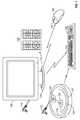
- FIG. 1shows an embodiment of a wireless power system in which a power base 100 is integrated into the base of a display 105 .
- the displayreceives its power through an electrical socket shown as 110 . That electrical power is also used to transmit wireless power from the base.
- the baseis preferably in a circular form to hold the monitor.
- the circular formhouses a circular loop coil.
- the size of the baseis large enough so that a sufficiently large coil diameter can be used.
- the poweris transmitted to a corresponding receiver and a number of different items.
- a wireless keyboard 130includes a wireless receiver 131 .
- the wireless mouse 140includes a corresponding receiver 141 .
- Wireless speakers shown as 150may also correspondingly include wireless power.
- the systemcan use a high frequency band of 13.56 MHz for transmission of power, or a low frequency band around 135 kHz.
- the baseeither the base of the PC screen or the discrete power base, each include a coil shown as 121 in parallel with a high voltage capacitor.
- the coilis connected to receive power from a power supply system that is powered by the AC power cord 123 .
- the power supply systemalso drives auxiliary structure including an antenna current sense circuit shown as 125 .
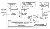
- FIG. 2illustrates a block diagram of a wireless power transmit circuit which can be formed in either the power base 100 or the discrete power base 120 .
- AC power 200is converted by a converter 205 e.g. a transformer or switched power supply, to another voltage level.
- the voltage level 210is then used to create a signal in a power amplifier 215 .
- the power amplifier 215produces an output 220 at a frequency which is resonant with the resonant value of the antenna 230 .
- the antenna 230can include an inductor 235 , and a high-voltage capacitor 240 .
- the current flowing through the antenna 230is sensed by a current sensor 245 . The amount of current will depend on coupling of the load, decoupling by external items, or others.
- the sensed amount of currentcan be returned to the controller 250 .
- the controller 250can control parameters of the power amplifier 215 , including changing its frequency and changing the amount of power it transmits.
- the controlcan be based, at least in part, on the sensed current sensed by the current indicator 245 .
- a signal indicative of the sensed currentis used by said transmit system to change the driving signal to the magnetically resonant antenna, based on an external characteristic of the medium into which transmission occurs. For example, this may be based on the number of interfering elements close to the phone, or based on the amount of loading by said magnetically resonant antenna.
- the characteristics of the way that the current changes when other detuning items are close and/or when multiple items are loading the devicemay be monitored and used to create a table or ruleset. That ruleset can then be used to set the way that the controller reacts to items being close.
- the rulesetcan be created by experimentation for any specific circuit and configuration.
- the antenna 300includes a tuning, matching and load control assembly 310 that carries out tuning, matching and also carries out load control.
- the tuning and matchingcan include one or both of switching in an additional capacitance and/or inductance; or removing some capacitance and/or inductance to better match the frequency the resonant frequency of the loaded antenna to the driving frequency. This may be done based on a detection that the dielectric objects are close enough to detune the antenna.
- the antennaincludes a coil 320 in series with a high-voltage capacitor 325 .
- the tuning and matchingmay also be responsive to a power indicator meter 315 .
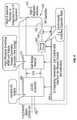
- the additional componentsmay include the parts as shown in FIG. 4 .
- the input AC power 400is input to an AC to DC converter 405 that can produce a variable DC output at 410 .
- a half bridge inverter 415can be controllable in various ways, including pulse width and supply voltage controlled electronic fine-tuning. By changing the characteristics of the inverter, matching to the antenna can be improved. The matching can also be carried out using a tuning circuit 420 .
- the antenna 430includes a coil 431 in series with a high-voltage capacitor 432 . The current through the antenna is also sensed by a current sensor 435 .
- a control unit 440creates frequencies and interfaces, to control the AC to DC converter, half bridge inverter 415 , and tuning circuit.
- the antenna 430may use the antenna of FIG. 3 that has overload protection built in.
- the overload protectionmay operate based on the current flow from current sensor 435 .
- the components in the devicemay be sized for specific levels of reactive and other voltage and current.
- the capacitor(s) in the antennacan have a specified voltage rating. These levels, especially the level of reactive voltage, can become very high during the power generation and reception.
- the overload protectioncan sense these levels and prevent the levels from exceeding the rated levels by more than a specified amount.
- FIG. 5shows a block diagram of the receiver device.
- a magnetic field induced by a transmittere.g. the transmitter 430 , is received into the receiving antenna 500 .
- the antennacan be formed of a coil 501 in series with a capacitor 502 .
- a receive control unit 510is powered by the received power and also may have a rechargeable battery that is charged by the power, to allow operation when the received power, and changes characteristics to improve the coupling and to optimize either or both of efficiency and/or power that is received.
- Received current 520is sensed, and a signal indicative thereof is sent to the control unit 510 .
- the control unitcorrespondingly controls a tuning unit 530 , rectifier 540 , and a DC to DC converter 550 .
- the rectifiercarries out synchronous rectification, with an adaptive load. This can avoid the diode voltage drop that would otherwise occur across a conventional diode rectifier.
- an electronic switchsuch as a MOSFET forms a half-bridge configuration that clamps the switching node to ⁇ 0.1V or less.
- the synchronous rectifierimproves the efficiency by placing a low-resistance conduction path across the diode rectifier.
- a load formed by the antennacan be changed by the control unit in order to improve the matching based on characteristics sensed by the control unit. For example, this can change capacitance and/ or inductance.
- the controllercan also change the characteristics of the rectifier, e.g, the frequency of the synchronous rectification, or the characteristics of the adaptive load presented by the rectifier.
- the DC to DC converter 550can carry out load adaptation based on specific sensed characteristics. Both the rectifier and the DC to DC converter 550 are controlled by the control unit 510 .
- the DC to DC converteralso carries out charging current control to the device battery, 560 , to avoid overcharging that battery or charging it too aggressively.
- the adaptive controlcan allow more aggressive control of the battery charging during low power times than during high-powered times. For example, if the receiver is receiving low amounts of current, then rectifier more aggressively steps up the power. This causes the DC to DC converter to step up the power to a sufficiently high voltage to drive the battery. Sensing the current through the antenna can be used to control the different items in the circuit and to determine how these different items should operate.
Landscapes
- Engineering & Computer Science (AREA)
- Computer Networks & Wireless Communication (AREA)
- Power Engineering (AREA)
- Charge And Discharge Circuits For Batteries Or The Like (AREA)
Abstract
Description
Claims (53)
Priority Applications (1)
| Application Number | Priority Date | Filing Date | Title |
|---|---|---|---|
| US12/400,703US8421267B2 (en) | 2008-03-10 | 2009-03-09 | Packaging and details of a wireless power device |
Applications Claiming Priority (2)
| Application Number | Priority Date | Filing Date | Title |
|---|---|---|---|
| US3534008P | 2008-03-10 | 2008-03-10 | |
| US12/400,703US8421267B2 (en) | 2008-03-10 | 2009-03-09 | Packaging and details of a wireless power device |
Publications (2)
| Publication Number | Publication Date |
|---|---|
| US20090224609A1 US20090224609A1 (en) | 2009-09-10 |
| US8421267B2true US8421267B2 (en) | 2013-04-16 |
Family
ID=41052876
Family Applications (1)
| Application Number | Title | Priority Date | Filing Date |
|---|---|---|---|
| US12/400,703Active2029-07-14US8421267B2 (en) | 2008-03-10 | 2009-03-09 | Packaging and details of a wireless power device |
Country Status (1)
| Country | Link |
|---|---|
| US (1) | US8421267B2 (en) |
Cited By (3)
| Publication number | Priority date | Publication date | Assignee | Title |
|---|---|---|---|---|
| WO2016050156A1 (en)* | 2014-10-02 | 2016-04-07 | 陈念祖 | Wireless charging system and device |
| US10183870B2 (en) | 2015-05-22 | 2019-01-22 | Access Business Group International Llc | Point-of-use water treatment system |
| US20250030274A1 (en)* | 2020-07-24 | 2025-01-23 | Nucurrent, Inc. | Area-Apportioned Wireless Power Antenna for Maximized Charging Volume |
Families Citing this family (153)
| Publication number | Priority date | Publication date | Assignee | Title |
|---|---|---|---|---|
| CN101860089B (en) | 2005-07-12 | 2013-02-06 | 麻省理工学院 | wireless non-radiative energy transfer |
| US7825543B2 (en) | 2005-07-12 | 2010-11-02 | Massachusetts Institute Of Technology | Wireless energy transfer |
| US11201500B2 (en) | 2006-01-31 | 2021-12-14 | Mojo Mobility, Inc. | Efficiencies and flexibilities in inductive (wireless) charging |
| US7952322B2 (en) | 2006-01-31 | 2011-05-31 | Mojo Mobility, Inc. | Inductive power source and charging system |
| US8169185B2 (en) | 2006-01-31 | 2012-05-01 | Mojo Mobility, Inc. | System and method for inductive charging of portable devices |
| US7948208B2 (en) | 2006-06-01 | 2011-05-24 | Mojo Mobility, Inc. | Power source, charging system, and inductive receiver for mobile devices |
| US11329511B2 (en) | 2006-06-01 | 2022-05-10 | Mojo Mobility Inc. | Power source, charging system, and inductive receiver for mobile devices |
| US8115448B2 (en) | 2007-06-01 | 2012-02-14 | Michael Sasha John | Systems and methods for wireless power |
| US9421388B2 (en) | 2007-06-01 | 2016-08-23 | Witricity Corporation | Power generation for implantable devices |
| US20110050164A1 (en) | 2008-05-07 | 2011-03-03 | Afshin Partovi | System and methods for inductive charging, and improvements and uses thereof |
| US20090284369A1 (en) | 2008-05-13 | 2009-11-19 | Qualcomm Incorporated | Transmit power control for a wireless charging system |
| US8878393B2 (en) | 2008-05-13 | 2014-11-04 | Qualcomm Incorporated | Wireless power transfer for vehicles |
| CN102099958B (en) | 2008-05-14 | 2013-12-25 | 麻省理工学院 | Wireless power transfer including interference enhancement |
| US8901779B2 (en) | 2008-09-27 | 2014-12-02 | Witricity Corporation | Wireless energy transfer with resonator arrays for medical applications |
| US8587153B2 (en) | 2008-09-27 | 2013-11-19 | Witricity Corporation | Wireless energy transfer using high Q resonators for lighting applications |
| US8569914B2 (en) | 2008-09-27 | 2013-10-29 | Witricity Corporation | Wireless energy transfer using object positioning for improved k |
| US8957549B2 (en) | 2008-09-27 | 2015-02-17 | Witricity Corporation | Tunable wireless energy transfer for in-vehicle applications |
| US9160203B2 (en) | 2008-09-27 | 2015-10-13 | Witricity Corporation | Wireless powered television |
| US8497601B2 (en) | 2008-09-27 | 2013-07-30 | Witricity Corporation | Wireless energy transfer converters |
| US9744858B2 (en) | 2008-09-27 | 2017-08-29 | Witricity Corporation | System for wireless energy distribution in a vehicle |
| US8410636B2 (en) | 2008-09-27 | 2013-04-02 | Witricity Corporation | Low AC resistance conductor designs |
| US8552592B2 (en) | 2008-09-27 | 2013-10-08 | Witricity Corporation | Wireless energy transfer with feedback control for lighting applications |
| US9105959B2 (en) | 2008-09-27 | 2015-08-11 | Witricity Corporation | Resonator enclosure |
| US8643326B2 (en) | 2008-09-27 | 2014-02-04 | Witricity Corporation | Tunable wireless energy transfer systems |
| US8471410B2 (en) | 2008-09-27 | 2013-06-25 | Witricity Corporation | Wireless energy transfer over distance using field shaping to improve the coupling factor |
| US8598743B2 (en) | 2008-09-27 | 2013-12-03 | Witricity Corporation | Resonator arrays for wireless energy transfer |
| US8686598B2 (en) | 2008-09-27 | 2014-04-01 | Witricity Corporation | Wireless energy transfer for supplying power and heat to a device |
| US8487480B1 (en) | 2008-09-27 | 2013-07-16 | Witricity Corporation | Wireless energy transfer resonator kit |
| US8772973B2 (en) | 2008-09-27 | 2014-07-08 | Witricity Corporation | Integrated resonator-shield structures |
| US8324759B2 (en) | 2008-09-27 | 2012-12-04 | Witricity Corporation | Wireless energy transfer using magnetic materials to shape field and reduce loss |
| US8947186B2 (en) | 2008-09-27 | 2015-02-03 | Witricity Corporation | Wireless energy transfer resonator thermal management |
| US8400017B2 (en) | 2008-09-27 | 2013-03-19 | Witricity Corporation | Wireless energy transfer for computer peripheral applications |
| US9318922B2 (en) | 2008-09-27 | 2016-04-19 | Witricity Corporation | Mechanically removable wireless power vehicle seat assembly |
| US9601261B2 (en) | 2008-09-27 | 2017-03-21 | Witricity Corporation | Wireless energy transfer using repeater resonators |
| US8937408B2 (en) | 2008-09-27 | 2015-01-20 | Witricity Corporation | Wireless energy transfer for medical applications |
| US8304935B2 (en) | 2008-09-27 | 2012-11-06 | Witricity Corporation | Wireless energy transfer using field shaping to reduce loss |
| US8629578B2 (en) | 2008-09-27 | 2014-01-14 | Witricity Corporation | Wireless energy transfer systems |
| US8461722B2 (en) | 2008-09-27 | 2013-06-11 | Witricity Corporation | Wireless energy transfer using conducting surfaces to shape field and improve K |
| US9515494B2 (en) | 2008-09-27 | 2016-12-06 | Witricity Corporation | Wireless power system including impedance matching network |
| US8963488B2 (en) | 2008-09-27 | 2015-02-24 | Witricity Corporation | Position insensitive wireless charging |
| US9544683B2 (en) | 2008-09-27 | 2017-01-10 | Witricity Corporation | Wirelessly powered audio devices |
| US9246336B2 (en) | 2008-09-27 | 2016-01-26 | Witricity Corporation | Resonator optimizations for wireless energy transfer |
| US9601266B2 (en) | 2008-09-27 | 2017-03-21 | Witricity Corporation | Multiple connected resonators with a single electronic circuit |
| US9093853B2 (en) | 2008-09-27 | 2015-07-28 | Witricity Corporation | Flexible resonator attachment |
| US8461720B2 (en) | 2008-09-27 | 2013-06-11 | Witricity Corporation | Wireless energy transfer using conducting surfaces to shape fields and reduce loss |
| US8901778B2 (en) | 2008-09-27 | 2014-12-02 | Witricity Corporation | Wireless energy transfer with variable size resonators for implanted medical devices |
| US8912687B2 (en) | 2008-09-27 | 2014-12-16 | Witricity Corporation | Secure wireless energy transfer for vehicle applications |
| EP3179640A1 (en) | 2008-09-27 | 2017-06-14 | WiTricity Corporation | Wireless energy transfer systems |
| US8466583B2 (en) | 2008-09-27 | 2013-06-18 | Witricity Corporation | Tunable wireless energy transfer for outdoor lighting applications |
| US8692412B2 (en) | 2008-09-27 | 2014-04-08 | Witricity Corporation | Temperature compensation in a wireless transfer system |
| US8692410B2 (en) | 2008-09-27 | 2014-04-08 | Witricity Corporation | Wireless energy transfer with frequency hopping |
| US9184595B2 (en) | 2008-09-27 | 2015-11-10 | Witricity Corporation | Wireless energy transfer in lossy environments |
| US8476788B2 (en) | 2008-09-27 | 2013-07-02 | Witricity Corporation | Wireless energy transfer with high-Q resonators using field shaping to improve K |
| US8933594B2 (en) | 2008-09-27 | 2015-01-13 | Witricity Corporation | Wireless energy transfer for vehicles |
| US9577436B2 (en) | 2008-09-27 | 2017-02-21 | Witricity Corporation | Wireless energy transfer for implantable devices |
| US8461721B2 (en) | 2008-09-27 | 2013-06-11 | Witricity Corporation | Wireless energy transfer using object positioning for low loss |
| US9601270B2 (en) | 2008-09-27 | 2017-03-21 | Witricity Corporation | Low AC resistance conductor designs |
| US8946938B2 (en) | 2008-09-27 | 2015-02-03 | Witricity Corporation | Safety systems for wireless energy transfer in vehicle applications |
| US8482158B2 (en) | 2008-09-27 | 2013-07-09 | Witricity Corporation | Wireless energy transfer using variable size resonators and system monitoring |
| US8669676B2 (en) | 2008-09-27 | 2014-03-11 | Witricity Corporation | Wireless energy transfer across variable distances using field shaping with magnetic materials to improve the coupling factor |
| US9396867B2 (en) | 2008-09-27 | 2016-07-19 | Witricity Corporation | Integrated resonator-shield structures |
| US9035499B2 (en) | 2008-09-27 | 2015-05-19 | Witricity Corporation | Wireless energy transfer for photovoltaic panels |
| US9065423B2 (en) | 2008-09-27 | 2015-06-23 | Witricity Corporation | Wireless energy distribution system |
| US8441154B2 (en) | 2008-09-27 | 2013-05-14 | Witricity Corporation | Multi-resonator wireless energy transfer for exterior lighting |
| US8723366B2 (en) | 2008-09-27 | 2014-05-13 | Witricity Corporation | Wireless energy transfer resonator enclosures |
| US8587155B2 (en) | 2008-09-27 | 2013-11-19 | Witricity Corporation | Wireless energy transfer using repeater resonators |
| US8907531B2 (en) | 2008-09-27 | 2014-12-09 | Witricity Corporation | Wireless energy transfer with variable size resonators for medical applications |
| US8922066B2 (en) | 2008-09-27 | 2014-12-30 | Witricity Corporation | Wireless energy transfer with multi resonator arrays for vehicle applications |
| US9106203B2 (en) | 2008-09-27 | 2015-08-11 | Witricity Corporation | Secure wireless energy transfer in medical applications |
| US8928276B2 (en) | 2008-09-27 | 2015-01-06 | Witricity Corporation | Integrated repeaters for cell phone applications |
| US8362651B2 (en) | 2008-10-01 | 2013-01-29 | Massachusetts Institute Of Technology | Efficient near-field wireless energy transfer using adiabatic system variations |
| US20100201311A1 (en)* | 2009-02-10 | 2010-08-12 | Qualcomm Incorporated | Wireless charging with separate process |
| US20100201312A1 (en) | 2009-02-10 | 2010-08-12 | Qualcomm Incorporated | Wireless power transfer for portable enclosures |
| US8854224B2 (en) | 2009-02-10 | 2014-10-07 | Qualcomm Incorporated | Conveying device information relating to wireless charging |
| US20100201201A1 (en)* | 2009-02-10 | 2010-08-12 | Qualcomm Incorporated | Wireless power transfer in public places |
| US9312924B2 (en) | 2009-02-10 | 2016-04-12 | Qualcomm Incorporated | Systems and methods relating to multi-dimensional wireless charging |
| US9013141B2 (en)* | 2009-04-28 | 2015-04-21 | Qualcomm Incorporated | Parasitic devices for wireless power transfer |
| US9318897B2 (en)* | 2009-07-21 | 2016-04-19 | Texas Instruments Incorporated | Reducing corruption of communication in a wireless power transmission system |
| JP5577896B2 (en)* | 2009-10-07 | 2014-08-27 | Tdk株式会社 | Wireless power supply apparatus and wireless power transmission system |
| JP5476917B2 (en)* | 2009-10-16 | 2014-04-23 | Tdk株式会社 | Wireless power feeding device, wireless power receiving device, and wireless power transmission system |
| JP5471283B2 (en)* | 2009-10-19 | 2014-04-16 | Tdk株式会社 | Wireless power feeding device, wireless power receiving device, and wireless power transmission system |
| US8829727B2 (en)* | 2009-10-30 | 2014-09-09 | Tdk Corporation | Wireless power feeder, wireless power transmission system, and table and table lamp using the same |
| EP2367263B1 (en) | 2010-03-19 | 2019-05-01 | TDK Corporation | Wireless power feeder, wireless power receiver, and wireless power transmission system |
| WO2011156768A2 (en) | 2010-06-11 | 2011-12-15 | Mojo Mobility, Inc. | System for wireless power transfer that supports interoperability, and multi-pole magnets for use therewith |
| US8829726B2 (en) | 2010-07-02 | 2014-09-09 | Tdk Corporation | Wireless power feeder and wireless power transmission system |
| US8729736B2 (en) | 2010-07-02 | 2014-05-20 | Tdk Corporation | Wireless power feeder and wireless power transmission system |
| JP5177187B2 (en)* | 2010-08-10 | 2013-04-03 | 株式会社村田製作所 | Power transmission system |
| US8829729B2 (en) | 2010-08-18 | 2014-09-09 | Tdk Corporation | Wireless power feeder, wireless power receiver, and wireless power transmission system |
| US8772977B2 (en) | 2010-08-25 | 2014-07-08 | Tdk Corporation | Wireless power feeder, wireless power transmission system, and table and table lamp using the same |
| US9602168B2 (en) | 2010-08-31 | 2017-03-21 | Witricity Corporation | Communication in wireless energy transfer systems |
| US8551163B2 (en) | 2010-10-07 | 2013-10-08 | Everheart Systems Inc. | Cardiac support systems and methods for chronic use |
| US9496924B2 (en) | 2010-12-10 | 2016-11-15 | Everheart Systems, Inc. | Mobile wireless power system |
| US9058928B2 (en) | 2010-12-14 | 2015-06-16 | Tdk Corporation | Wireless power feeder and wireless power transmission system |
| US8664803B2 (en) | 2010-12-28 | 2014-03-04 | Tdk Corporation | Wireless power feeder, wireless power receiver, and wireless power transmission system |
| US8669677B2 (en) | 2010-12-28 | 2014-03-11 | Tdk Corporation | Wireless power feeder, wireless power receiver, and wireless power transmission system |
| US8800738B2 (en) | 2010-12-28 | 2014-08-12 | Tdk Corporation | Wireless power feeder and wireless power receiver |
| US9143010B2 (en) | 2010-12-28 | 2015-09-22 | Tdk Corporation | Wireless power transmission system for selectively powering one or more of a plurality of receivers |
| KR101171938B1 (en)* | 2010-12-30 | 2012-08-07 | 전자부품연구원 | Multi-node wireless power transmission system and charging method therof using magnetic resonance induction |
| CN102907087B (en)* | 2011-01-13 | 2015-09-09 | 海尔集团公司 | Remote control system for tailless TV and corresponding tailless TV |
| US9496732B2 (en) | 2011-01-18 | 2016-11-15 | Mojo Mobility, Inc. | Systems and methods for wireless power transfer |
| US11342777B2 (en) | 2011-01-18 | 2022-05-24 | Mojo Mobility, Inc. | Powering and/or charging with more than one protocol |
| US9178369B2 (en) | 2011-01-18 | 2015-11-03 | Mojo Mobility, Inc. | Systems and methods for providing positioning freedom, and support of different voltages, protocols, and power levels in a wireless power system |
| US10115520B2 (en) | 2011-01-18 | 2018-10-30 | Mojo Mobility, Inc. | Systems and method for wireless power transfer |
| US9118357B2 (en) | 2011-02-17 | 2015-08-25 | Qualcomm Incorporated | Systems and methods for controlling output power of a wireless power transmitter |
| US8742627B2 (en) | 2011-03-01 | 2014-06-03 | Tdk Corporation | Wireless power feeder |
| US9356449B2 (en) | 2011-03-01 | 2016-05-31 | Tdk Corporation | Wireless power receiver, wireless power transmission system, and power controller |
| US8970069B2 (en) | 2011-03-28 | 2015-03-03 | Tdk Corporation | Wireless power receiver and wireless power transmission system |
| JP2012217228A (en)* | 2011-03-31 | 2012-11-08 | Equos Research Co Ltd | Power transmission system |
| US9948145B2 (en) | 2011-07-08 | 2018-04-17 | Witricity Corporation | Wireless power transfer for a seat-vest-helmet system |
| CN108110907B (en) | 2011-08-04 | 2022-08-02 | 韦特里西提公司 | Tunable wireless power supply architecture |
| EP2754222B1 (en) | 2011-09-09 | 2015-11-18 | Witricity Corporation | Foreign object detection in wireless energy transfer systems |
| US20130062966A1 (en) | 2011-09-12 | 2013-03-14 | Witricity Corporation | Reconfigurable control architectures and algorithms for electric vehicle wireless energy transfer systems |
| US9812902B2 (en)* | 2011-09-13 | 2017-11-07 | Samsung Electronics Co., Ltd. | Wireless electromagnetic receiver and wireless power transfer system |
| US9479227B2 (en)* | 2011-09-13 | 2016-10-25 | Samsung Electronics Co., Ltd. | Wireless electromagnetic receiver and wireless power transfer system |
| US9509179B2 (en)* | 2011-09-13 | 2016-11-29 | Samsung Electronics Co., Ltd. | Wireless electromagnetic receiver and wireless power transfer system |
| US9318257B2 (en) | 2011-10-18 | 2016-04-19 | Witricity Corporation | Wireless energy transfer for packaging |
| CA2853824A1 (en) | 2011-11-04 | 2013-05-10 | Witricity Corporation | Wireless energy transfer modeling tool |
| DE102011086904A1 (en)* | 2011-11-23 | 2013-05-23 | Robert Bosch Gmbh | Device and method for inductive energy transmission |
| US9537324B2 (en) | 2011-12-14 | 2017-01-03 | Fleetwood Group, Inc. | Audience response system with batteryless response units |
| JP2015508987A (en) | 2012-01-26 | 2015-03-23 | ワイトリシティ コーポレーションWitricity Corporation | Wireless energy transmission with reduced field |
| US9722447B2 (en) | 2012-03-21 | 2017-08-01 | Mojo Mobility, Inc. | System and method for charging or powering devices, such as robots, electric vehicles, or other mobile devices or equipment |
| US20130271069A1 (en) | 2012-03-21 | 2013-10-17 | Mojo Mobility, Inc. | Systems and methods for wireless power transfer |
| US9343922B2 (en) | 2012-06-27 | 2016-05-17 | Witricity Corporation | Wireless energy transfer for rechargeable batteries |
| US9287607B2 (en) | 2012-07-31 | 2016-03-15 | Witricity Corporation | Resonator fine tuning |
| US9735701B2 (en)* | 2012-08-03 | 2017-08-15 | Mediatek Singapore Ptd. Ltd. | Circuit and method for measuring available power in a wireless power system |
| US9859956B2 (en) | 2012-08-24 | 2018-01-02 | Qualcomm Incorporated | Power supply control in wireless power transfer systems |
| US9595378B2 (en) | 2012-09-19 | 2017-03-14 | Witricity Corporation | Resonator enclosure |
| EP2909912B1 (en) | 2012-10-19 | 2022-08-10 | WiTricity Corporation | Foreign object detection in wireless energy transfer systems |
| US9842684B2 (en) | 2012-11-16 | 2017-12-12 | Witricity Corporation | Systems and methods for wireless power system with improved performance and/or ease of use |
| US9837846B2 (en) | 2013-04-12 | 2017-12-05 | Mojo Mobility, Inc. | System and method for powering or charging receivers or devices having small surface areas or volumes |
| GB2517679A (en) | 2013-06-25 | 2015-03-04 | Bombardier Transp Gmbh | Object detection system and method for operating an object detection system |
| US9857821B2 (en) | 2013-08-14 | 2018-01-02 | Witricity Corporation | Wireless power transfer frequency adjustment |
| US9780573B2 (en) | 2014-02-03 | 2017-10-03 | Witricity Corporation | Wirelessly charged battery system |
| US9952266B2 (en) | 2014-02-14 | 2018-04-24 | Witricity Corporation | Object detection for wireless energy transfer systems |
| US9892849B2 (en) | 2014-04-17 | 2018-02-13 | Witricity Corporation | Wireless power transfer systems with shield openings |
| US9842687B2 (en) | 2014-04-17 | 2017-12-12 | Witricity Corporation | Wireless power transfer systems with shaped magnetic components |
| US9837860B2 (en) | 2014-05-05 | 2017-12-05 | Witricity Corporation | Wireless power transmission systems for elevators |
| JP2017518018A (en) | 2014-05-07 | 2017-06-29 | ワイトリシティ コーポレーションWitricity Corporation | Foreign object detection in wireless energy transmission systems |
| FR3021824B1 (en)* | 2014-05-30 | 2016-07-01 | Thales Sa | ANTENNA ADAPTER |
| US9954375B2 (en) | 2014-06-20 | 2018-04-24 | Witricity Corporation | Wireless power transfer systems for surfaces |
| CN107258046B (en) | 2014-07-08 | 2020-07-17 | 无线电力公司 | Resonator equalization in wireless power transfer systems |
| US10574091B2 (en) | 2014-07-08 | 2020-02-25 | Witricity Corporation | Enclosures for high power wireless power transfer systems |
| US9843217B2 (en) | 2015-01-05 | 2017-12-12 | Witricity Corporation | Wireless energy transfer for wearables |
| US10248899B2 (en) | 2015-10-06 | 2019-04-02 | Witricity Corporation | RFID tag and transponder detection in wireless energy transfer systems |
| US9929721B2 (en) | 2015-10-14 | 2018-03-27 | Witricity Corporation | Phase and amplitude detection in wireless energy transfer systems |
| WO2017070227A1 (en) | 2015-10-19 | 2017-04-27 | Witricity Corporation | Foreign object detection in wireless energy transfer systems |
| WO2017070009A1 (en) | 2015-10-22 | 2017-04-27 | Witricity Corporation | Dynamic tuning in wireless energy transfer systems |
| US10075019B2 (en) | 2015-11-20 | 2018-09-11 | Witricity Corporation | Voltage source isolation in wireless power transfer systems |
| WO2017136491A1 (en) | 2016-02-02 | 2017-08-10 | Witricity Corporation | Controlling wireless power transfer systems |
| CN114123540B (en) | 2016-02-08 | 2024-08-20 | 韦特里西提公司 | Variable capacitance device and high-power wireless energy transmission system |
| WO2019006376A1 (en) | 2017-06-29 | 2019-01-03 | Witricity Corporation | Protection and control of wireless power systems |
| US11444485B2 (en) | 2019-02-05 | 2022-09-13 | Mojo Mobility, Inc. | Inductive charging system with charging electronics physically separated from charging coil |
| CN113036938A (en)* | 2021-03-09 | 2021-06-25 | 奇瑞商用车(安徽)有限公司 | Wireless charging system that electric automobile can regulate and control |
Citations (15)
| Publication number | Priority date | Publication date | Assignee | Title |
|---|---|---|---|---|
| US5301358A (en)* | 1988-12-05 | 1994-04-05 | Seiko Corp. | Automatic antenna tuning method and apparatus |
| US5929598A (en) | 1996-07-03 | 1999-07-27 | Uniden Corporation | Noncontact charging device, charger, cordless electric equipment, and noncontact charger |
| US6028413A (en) | 1997-09-19 | 2000-02-22 | Perdix Oy | Charging device for batteries in a mobile electrical device |
| US20030015479A1 (en) | 1999-06-21 | 2003-01-23 | Kuennen Roy W. | Inductively coupled ballast circuit |
| US20040130916A1 (en)* | 1999-06-21 | 2004-07-08 | Baarman David W. | Adaptive inductive power supply |
| US20050131495A1 (en) | 2002-06-28 | 2005-06-16 | Jordi Parramon | Systems and methods for providing power to a battery in an implantable stimulator |
| US20050127867A1 (en) | 2003-12-12 | 2005-06-16 | Microsoft Corporation | Inductively charged battery pack |
| US6972543B1 (en) | 2003-08-21 | 2005-12-06 | Stryker Corporation | Series resonant inductive charging circuit |
| US20070222542A1 (en) | 2005-07-12 | 2007-09-27 | Joannopoulos John D | Wireless non-radiative energy transfer |
| US7385357B2 (en) | 1999-06-21 | 2008-06-10 | Access Business Group International Llc | Inductively coupled ballast circuit |
| US20080191897A1 (en) | 2005-11-16 | 2008-08-14 | Mccollough Norman D | Photoelectric controller for electric street lighting |
| US20090212636A1 (en) | 2008-01-10 | 2009-08-27 | Nigel Power Llc | Wireless desktop IT environment |
| US20090284245A1 (en) | 2008-05-13 | 2009-11-19 | Qualcomm Incorporated | Wireless power transfer for appliances and equipments |
| US20100165667A1 (en)* | 2006-12-01 | 2010-07-01 | Artusi Daniel A | Power System with Power Converters Having an Adaptive Controller |
| US7825543B2 (en) | 2005-07-12 | 2010-11-02 | Massachusetts Institute Of Technology | Wireless energy transfer |
Family Cites Families (1)
| Publication number | Priority date | Publication date | Assignee | Title |
|---|---|---|---|---|
| US7638383B2 (en)* | 2006-09-19 | 2009-12-29 | Intel Corporation | Faceted catalytic dots for directed nanotube growth |
- 2009
- 2009-03-09USUS12/400,703patent/US8421267B2/enactiveActive
Patent Citations (18)
| Publication number | Priority date | Publication date | Assignee | Title |
|---|---|---|---|---|
| US5301358A (en)* | 1988-12-05 | 1994-04-05 | Seiko Corp. | Automatic antenna tuning method and apparatus |
| US5929598A (en) | 1996-07-03 | 1999-07-27 | Uniden Corporation | Noncontact charging device, charger, cordless electric equipment, and noncontact charger |
| US6028413A (en) | 1997-09-19 | 2000-02-22 | Perdix Oy | Charging device for batteries in a mobile electrical device |
| US20070171681A1 (en) | 1999-06-21 | 2007-07-26 | Access Business Group International Llc | Adaptive inductive power supply |
| US20030015479A1 (en) | 1999-06-21 | 2003-01-23 | Kuennen Roy W. | Inductively coupled ballast circuit |
| US7385357B2 (en) | 1999-06-21 | 2008-06-10 | Access Business Group International Llc | Inductively coupled ballast circuit |
| US20040130916A1 (en)* | 1999-06-21 | 2004-07-08 | Baarman David W. | Adaptive inductive power supply |
| US20050131495A1 (en) | 2002-06-28 | 2005-06-16 | Jordi Parramon | Systems and methods for providing power to a battery in an implantable stimulator |
| US6972543B1 (en) | 2003-08-21 | 2005-12-06 | Stryker Corporation | Series resonant inductive charging circuit |
| US20050127867A1 (en) | 2003-12-12 | 2005-06-16 | Microsoft Corporation | Inductively charged battery pack |
| US20070222542A1 (en) | 2005-07-12 | 2007-09-27 | Joannopoulos John D | Wireless non-radiative energy transfer |
| US7741734B2 (en) | 2005-07-12 | 2010-06-22 | Massachusetts Institute Of Technology | Wireless non-radiative energy transfer |
| US7825543B2 (en) | 2005-07-12 | 2010-11-02 | Massachusetts Institute Of Technology | Wireless energy transfer |
| US20100327661A1 (en)* | 2005-07-12 | 2010-12-30 | Aristeidis Karalis | Packaging and details of a wireless power device |
| US20080191897A1 (en) | 2005-11-16 | 2008-08-14 | Mccollough Norman D | Photoelectric controller for electric street lighting |
| US20100165667A1 (en)* | 2006-12-01 | 2010-07-01 | Artusi Daniel A | Power System with Power Converters Having an Adaptive Controller |
| US20090212636A1 (en) | 2008-01-10 | 2009-08-27 | Nigel Power Llc | Wireless desktop IT environment |
| US20090284245A1 (en) | 2008-05-13 | 2009-11-19 | Qualcomm Incorporated | Wireless power transfer for appliances and equipments |
Non-Patent Citations (4)
| Title |
|---|
| "Efficient wireless non-radiative mid-range energy transfer", MITpaper, publication and date unknown, believed to be 2007. |
| "Wireless Non-Radiative Energy Transfer", MIT paper, publication and date unknown, believed to be 2007. |
| "Wireless Power Transfer via Strongly Coupled Magnetic Resonances", Kurs et al, Science Express, Jun. 7, 2007. |
| "Wireless Power Transfer via Strongly Coupled Magnetic Resonances", Kurs et al, scimag.org, Jul. 6, 2007. |
Cited By (4)
| Publication number | Priority date | Publication date | Assignee | Title |
|---|---|---|---|---|
| WO2016050156A1 (en)* | 2014-10-02 | 2016-04-07 | 陈念祖 | Wireless charging system and device |
| US10183870B2 (en) | 2015-05-22 | 2019-01-22 | Access Business Group International Llc | Point-of-use water treatment system |
| US20250030274A1 (en)* | 2020-07-24 | 2025-01-23 | Nucurrent, Inc. | Area-Apportioned Wireless Power Antenna for Maximized Charging Volume |
| US12316137B2 (en)* | 2020-07-24 | 2025-05-27 | Nucurrent, Inc. | Area-apportioned wireless power antenna for maximized charging volume |
Also Published As
| Publication number | Publication date |
|---|---|
| US20090224609A1 (en) | 2009-09-10 |
Similar Documents
| Publication | Publication Date | Title |
|---|---|---|
| US8421267B2 (en) | Packaging and details of a wireless power device | |
| US9812893B2 (en) | Wireless power receiver | |
| US10205353B2 (en) | Apparatus and method for charging control in wireless charging system | |
| US9203475B2 (en) | Wireless power transmission system, wireless power receiving apparatus, and wireless power receiving method | |
| US10069340B2 (en) | Wireless power receiver for adjusting magnitude of wireless power | |
| JP5759388B2 (en) | System and method for multi-dimensional wireless charging | |
| US9847675B2 (en) | Power receiving device and power feeding system | |
| KR102042685B1 (en) | Wireless power transmission apparatus and wireless power reception apparatus | |
| US20160056641A1 (en) | Wireless power transmission system and method of controlling the same | |
| US20090243397A1 (en) | Packaging and Details of a Wireless Power device | |
| US20130257167A1 (en) | Apparatuses, systems, and methods for power transfer adjustment in wireless power transfer systems | |
| US12074462B2 (en) | Wireless charging device, a receiver device, and an associated method thereof | |
| EP2745412A1 (en) | Wireless power receiver with multiple receiver coils | |
| KR20140031783A (en) | Wireless power transmitter for excluding cross connected wireless power receiver and method for controlling thereof | |
| US20090309550A1 (en) | Auto-rechargeable wireless computer peripheral | |
| CN107646162A (en) | Wireless Power Transfer Using Field Changing Circuits | |
| KR102198935B1 (en) | Apparatus and method for detecting foreign object in wireless power transmitting system | |
| KR20140071233A (en) | Method and apparatus for charging control in wireless charge system | |
| KR20210086589A (en) | Apparatus and method for detecting foreign object in wireless power transmitting system | |
| KR20150045602A (en) | Remote Controlled Charging Device based on Resonant Method | |
| KR101712647B1 (en) | Auxiliary battery for wirelessly charging and discharging | |
| KR101839527B1 (en) | Power apparatus with adjusting the rectified voltage for high efficiency wireless power transfer | |
| KR20190083584A (en) | Noise Reduction Wireless Power Transmission Method and Apparatus | |
| US11962175B2 (en) | Electronic device to wirelessly receive power and operating method thereof | |
| KR20170005589A (en) | Apparatus for transmitting wireless power and system for transmitting wireless power |
Legal Events
| Date | Code | Title | Description |
|---|---|---|---|
| AS | Assignment | Owner name:NIGEL POWER LLC, CALIFORNIA Free format text:ASSIGNMENT OF ASSIGNORS INTEREST;ASSIGNORS:COOK, NIGEL P;SIEBER, LUKAS;WIDMER, HANSPETER;REEL/FRAME:022687/0307;SIGNING DATES FROM 20090326 TO 20090330 Owner name:NIGEL POWER LLC, CALIFORNIA Free format text:ASSIGNMENT OF ASSIGNORS INTEREST;ASSIGNORS:COOK, NIGEL P;SIEBER, LUKAS;WIDMER, HANSPETER;SIGNING DATES FROM 20090326 TO 20090330;REEL/FRAME:022687/0307 | |
| AS | Assignment | Owner name:QUALCOMM INCORPORATED, CALIFORNIA Free format text:ASSIGNMENT OF ASSIGNORS INTEREST;ASSIGNOR:NIGEL POWER LLC;REEL/FRAME:023445/0266 Effective date:20090519 Owner name:QUALCOMM INCORPORATED,CALIFORNIA Free format text:ASSIGNMENT OF ASSIGNORS INTEREST;ASSIGNOR:NIGEL POWER LLC;REEL/FRAME:023445/0266 Effective date:20090519 | |
| AS | Assignment | Owner name:QUALCOMM INCORPORATED, CALIFORNIA Free format text:ASSIGNMENT OF ASSIGNORS INTEREST;ASSIGNORS:COOK, NIGEL P;SIEBER, LUKAS;WIDMER, HANSPETER;SIGNING DATES FROM 20091214 TO 20091215;REEL/FRAME:025491/0571 | |
| FEPP | Fee payment procedure | Free format text:PAYOR NUMBER ASSIGNED (ORIGINAL EVENT CODE: ASPN); ENTITY STATUS OF PATENT OWNER: LARGE ENTITY | |
| STCF | Information on status: patent grant | Free format text:PATENTED CASE | |
| FPAY | Fee payment | Year of fee payment:4 | |
| MAFP | Maintenance fee payment | Free format text:PAYMENT OF MAINTENANCE FEE, 8TH YEAR, LARGE ENTITY (ORIGINAL EVENT CODE: M1552); ENTITY STATUS OF PATENT OWNER: LARGE ENTITY Year of fee payment:8 | |
| MAFP | Maintenance fee payment | Free format text:PAYMENT OF MAINTENANCE FEE, 12TH YEAR, LARGE ENTITY (ORIGINAL EVENT CODE: M1553); ENTITY STATUS OF PATENT OWNER: LARGE ENTITY Year of fee payment:12 |