US8419787B2 - Implantable intraluminal device and method of using same in treating aneurysms - Google Patents
Implantable intraluminal device and method of using same in treating aneurysmsDownload PDFInfo
- Publication number
- US8419787B2 US8419787B2US12/709,483US70948310AUS8419787B2US 8419787 B2US8419787 B2US 8419787B2US 70948310 AUS70948310 AUS 70948310AUS 8419787 B2US8419787 B2US 8419787B2
- Authority
- US
- United States
- Prior art keywords
- filaments
- intraluminal device
- aneurysm
- vessel
- tubular body
- Prior art date
- Legal status (The legal status is an assumption and is not a legal conclusion. Google has not performed a legal analysis and makes no representation as to the accuracy of the status listed.)
- Expired - Fee Related
Links
Images


Classifications
- A—HUMAN NECESSITIES
- A61—MEDICAL OR VETERINARY SCIENCE; HYGIENE
- A61F—FILTERS IMPLANTABLE INTO BLOOD VESSELS; PROSTHESES; DEVICES PROVIDING PATENCY TO, OR PREVENTING COLLAPSING OF, TUBULAR STRUCTURES OF THE BODY, e.g. STENTS; ORTHOPAEDIC, NURSING OR CONTRACEPTIVE DEVICES; FOMENTATION; TREATMENT OR PROTECTION OF EYES OR EARS; BANDAGES, DRESSINGS OR ABSORBENT PADS; FIRST-AID KITS
- A61F2/00—Filters implantable into blood vessels; Prostheses, i.e. artificial substitutes or replacements for parts of the body; Appliances for connecting them with the body; Devices providing patency to, or preventing collapsing of, tubular structures of the body, e.g. stents
- A61F2/82—Devices providing patency to, or preventing collapsing of, tubular structures of the body, e.g. stents
- A61F2/86—Stents in a form characterised by the wire-like elements; Stents in the form characterised by a net-like or mesh-like structure
- A61F2/90—Stents in a form characterised by the wire-like elements; Stents in the form characterised by a net-like or mesh-like structure characterised by a net-like or mesh-like structure
- A—HUMAN NECESSITIES
- A61—MEDICAL OR VETERINARY SCIENCE; HYGIENE
- A61F—FILTERS IMPLANTABLE INTO BLOOD VESSELS; PROSTHESES; DEVICES PROVIDING PATENCY TO, OR PREVENTING COLLAPSING OF, TUBULAR STRUCTURES OF THE BODY, e.g. STENTS; ORTHOPAEDIC, NURSING OR CONTRACEPTIVE DEVICES; FOMENTATION; TREATMENT OR PROTECTION OF EYES OR EARS; BANDAGES, DRESSINGS OR ABSORBENT PADS; FIRST-AID KITS
- A61F2/00—Filters implantable into blood vessels; Prostheses, i.e. artificial substitutes or replacements for parts of the body; Appliances for connecting them with the body; Devices providing patency to, or preventing collapsing of, tubular structures of the body, e.g. stents
- A61F2/02—Prostheses implantable into the body
- A61F2/04—Hollow or tubular parts of organs, e.g. bladders, tracheae, bronchi or bile ducts
- A61F2/06—Blood vessels
- A61F2/07—Stent-grafts
- A—HUMAN NECESSITIES
- A61—MEDICAL OR VETERINARY SCIENCE; HYGIENE
- A61F—FILTERS IMPLANTABLE INTO BLOOD VESSELS; PROSTHESES; DEVICES PROVIDING PATENCY TO, OR PREVENTING COLLAPSING OF, TUBULAR STRUCTURES OF THE BODY, e.g. STENTS; ORTHOPAEDIC, NURSING OR CONTRACEPTIVE DEVICES; FOMENTATION; TREATMENT OR PROTECTION OF EYES OR EARS; BANDAGES, DRESSINGS OR ABSORBENT PADS; FIRST-AID KITS
- A61F2/00—Filters implantable into blood vessels; Prostheses, i.e. artificial substitutes or replacements for parts of the body; Appliances for connecting them with the body; Devices providing patency to, or preventing collapsing of, tubular structures of the body, e.g. stents
- A61F2/82—Devices providing patency to, or preventing collapsing of, tubular structures of the body, e.g. stents
- A—HUMAN NECESSITIES
- A61—MEDICAL OR VETERINARY SCIENCE; HYGIENE
- A61F—FILTERS IMPLANTABLE INTO BLOOD VESSELS; PROSTHESES; DEVICES PROVIDING PATENCY TO, OR PREVENTING COLLAPSING OF, TUBULAR STRUCTURES OF THE BODY, e.g. STENTS; ORTHOPAEDIC, NURSING OR CONTRACEPTIVE DEVICES; FOMENTATION; TREATMENT OR PROTECTION OF EYES OR EARS; BANDAGES, DRESSINGS OR ABSORBENT PADS; FIRST-AID KITS
- A61F2/00—Filters implantable into blood vessels; Prostheses, i.e. artificial substitutes or replacements for parts of the body; Appliances for connecting them with the body; Devices providing patency to, or preventing collapsing of, tubular structures of the body, e.g. stents
- A61F2/02—Prostheses implantable into the body
- A61F2/04—Hollow or tubular parts of organs, e.g. bladders, tracheae, bronchi or bile ducts
- A61F2/06—Blood vessels
- A61F2002/065—Y-shaped blood vessels
- A—HUMAN NECESSITIES
- A61—MEDICAL OR VETERINARY SCIENCE; HYGIENE
- A61F—FILTERS IMPLANTABLE INTO BLOOD VESSELS; PROSTHESES; DEVICES PROVIDING PATENCY TO, OR PREVENTING COLLAPSING OF, TUBULAR STRUCTURES OF THE BODY, e.g. STENTS; ORTHOPAEDIC, NURSING OR CONTRACEPTIVE DEVICES; FOMENTATION; TREATMENT OR PROTECTION OF EYES OR EARS; BANDAGES, DRESSINGS OR ABSORBENT PADS; FIRST-AID KITS
- A61F2/00—Filters implantable into blood vessels; Prostheses, i.e. artificial substitutes or replacements for parts of the body; Appliances for connecting them with the body; Devices providing patency to, or preventing collapsing of, tubular structures of the body, e.g. stents
- A61F2/02—Prostheses implantable into the body
- A61F2/04—Hollow or tubular parts of organs, e.g. bladders, tracheae, bronchi or bile ducts
- A61F2/06—Blood vessels
- A61F2002/068—Modifying the blood flow model, e.g. by diffuser or deflector
- A—HUMAN NECESSITIES
- A61—MEDICAL OR VETERINARY SCIENCE; HYGIENE
- A61F—FILTERS IMPLANTABLE INTO BLOOD VESSELS; PROSTHESES; DEVICES PROVIDING PATENCY TO, OR PREVENTING COLLAPSING OF, TUBULAR STRUCTURES OF THE BODY, e.g. STENTS; ORTHOPAEDIC, NURSING OR CONTRACEPTIVE DEVICES; FOMENTATION; TREATMENT OR PROTECTION OF EYES OR EARS; BANDAGES, DRESSINGS OR ABSORBENT PADS; FIRST-AID KITS
- A61F2/00—Filters implantable into blood vessels; Prostheses, i.e. artificial substitutes or replacements for parts of the body; Appliances for connecting them with the body; Devices providing patency to, or preventing collapsing of, tubular structures of the body, e.g. stents
- A61F2/82—Devices providing patency to, or preventing collapsing of, tubular structures of the body, e.g. stents
- A61F2002/821—Ostial stents
- A—HUMAN NECESSITIES
- A61—MEDICAL OR VETERINARY SCIENCE; HYGIENE
- A61F—FILTERS IMPLANTABLE INTO BLOOD VESSELS; PROSTHESES; DEVICES PROVIDING PATENCY TO, OR PREVENTING COLLAPSING OF, TUBULAR STRUCTURES OF THE BODY, e.g. STENTS; ORTHOPAEDIC, NURSING OR CONTRACEPTIVE DEVICES; FOMENTATION; TREATMENT OR PROTECTION OF EYES OR EARS; BANDAGES, DRESSINGS OR ABSORBENT PADS; FIRST-AID KITS
- A61F2/00—Filters implantable into blood vessels; Prostheses, i.e. artificial substitutes or replacements for parts of the body; Appliances for connecting them with the body; Devices providing patency to, or preventing collapsing of, tubular structures of the body, e.g. stents
- A61F2/82—Devices providing patency to, or preventing collapsing of, tubular structures of the body, e.g. stents
- A61F2002/823—Stents, different from stent-grafts, adapted to cover an aneurysm
- A—HUMAN NECESSITIES
- A61—MEDICAL OR VETERINARY SCIENCE; HYGIENE
- A61F—FILTERS IMPLANTABLE INTO BLOOD VESSELS; PROSTHESES; DEVICES PROVIDING PATENCY TO, OR PREVENTING COLLAPSING OF, TUBULAR STRUCTURES OF THE BODY, e.g. STENTS; ORTHOPAEDIC, NURSING OR CONTRACEPTIVE DEVICES; FOMENTATION; TREATMENT OR PROTECTION OF EYES OR EARS; BANDAGES, DRESSINGS OR ABSORBENT PADS; FIRST-AID KITS
- A61F2250/00—Special features of prostheses classified in groups A61F2/00 - A61F2/26 or A61F2/82 or A61F9/00 or A61F11/00 or subgroups thereof
- A61F2250/0014—Special features of prostheses classified in groups A61F2/00 - A61F2/26 or A61F2/82 or A61F9/00 or A61F11/00 or subgroups thereof having different values of a given property or geometrical feature, e.g. mechanical property or material property, at different locations within the same prosthesis
- A61F2250/0023—Special features of prostheses classified in groups A61F2/00 - A61F2/26 or A61F2/82 or A61F9/00 or A61F11/00 or subgroups thereof having different values of a given property or geometrical feature, e.g. mechanical property or material property, at different locations within the same prosthesis differing in porosity
- Y—GENERAL TAGGING OF NEW TECHNOLOGICAL DEVELOPMENTS; GENERAL TAGGING OF CROSS-SECTIONAL TECHNOLOGIES SPANNING OVER SEVERAL SECTIONS OF THE IPC; TECHNICAL SUBJECTS COVERED BY FORMER USPC CROSS-REFERENCE ART COLLECTIONS [XRACs] AND DIGESTS
- Y10—TECHNICAL SUBJECTS COVERED BY FORMER USPC
- Y10S—TECHNICAL SUBJECTS COVERED BY FORMER USPC CROSS-REFERENCE ART COLLECTIONS [XRACs] AND DIGESTS
- Y10S623/00—Prosthesis, i.e. artificial body members, parts thereof, or aids and accessories therefor
- Y10S623/909—Method or apparatus for assembling prosthetic
Definitions
- the present inventionrelates to intraluminal devices implantable in a blood vessel for the treatment of aneurysms especially basal apex aneurysms.
- the inventionalso relates to methods of treating aneurysms using such intraluminal devices.
- Intracranial aneurysmsare the main cause of nontraumatic subarachnoid hemorrhage and are responsible for about 25% of all deaths relating to cerebrovascular events. Autopsy studies show that the overall frequency of intracranial aneurysms in the general population is approximately 5 percent and suggest that 10 to 15 million persons in the United States have or will have intracranial aneurysms [1]. In approximately 15,000 cases (6 cases per 100,000 persons per year), intracranial aneurysms rupture every year in North America [2].
- SAHsubarachnoid aneurysmal hemorrhage
- the primary goal of treatments for intracranial aneurysmis prevention of the rupture of the aneurysms, thereby preventing bleeding or rebleeding.
- the extravascular approachinvolves surgery or microsurgery of the aneurysm.
- One surgical procedureis to apply a metallic clip or a suture-ligation across the artery feeding the aneurysm (neck), thereby allowing the aneurysm to clot off and hopefully shrink.
- Another surgical procedureis to “surgically reconstruct” the aneurysmal portion of the artery, by surgically cut out the aneurysm and repairing the vessel by using a natural or synthetic vessel graft. Both of these surgical procedures typically require general anesthesia, craniotomy, brain retraction, and dissection of the arachnoid around the neck of the aneurysm.
- Surgical treatment of vascular intracranial aneurysmis accompanied by a mortality rate of 3.8% and a morbidity rate of 10.9% [3]. Because of the high mortality and morbidity rates, and because the condition of many patients does not permit them to undergo an open operation, the surgical procedure is often delayed or not practical. For this reason the prior art has sought alternative means of treatment.
- microcathetersmade possible the use of endovascular (catheter-based) procedures.
- the major advantage of the endovascular proceduresis that they do not require the use of open surgery. They are generally more beneficial and have much lower mortality and morbidity rates than the extravascular procedures.
- the methodhas 4% morbidity and 1% mortality rate and achieves complete aneurysm occlusion in only 52% to 78% of the cases in which it is employed.
- the relatively low success rateis due to technical limitations (e.g., coil flexibility, shape, and dimensions) which prevent tight packing of the sac of the aneurysm, especially aneurysms with wide necks [3].
- Other difficultiesare associated with the presence of preexisting thrombus within the aneurysm cavity, which may be sheared off into the parent trunk leading to parent artery occlusion.
- aneurysm perforationmay occur during placement of coils into the aneurysm. Additionally, occurrence of coil movement and compaction may foster aneurysm revascularization or growth.
- detachable balloonswhen inflated, typically do not conform to the interior configuration of the aneurysm sac. Instead, the aneurysm sac is forced to conform to the exterior surface of the detachable balloon. Thus, there is an increased risk that the detachable balloon will rupture the sac of the aneurysm.
- Stents having portions of different permeabilitiesare disclosed, for example, in McCrory U.S. Pat. No. 5,951,599, Brown et al U.S. Pat. No. 6,093,199, Wallsten U.S. Pat. No. 4,954,126, and Dubrul U.S. Pat. No. 6,258,115.
- the McCrory patentdiscloses a braided stent having a first portion with a relatively high porosity index so as to be highly permeable to blood flow, and a second portion of lower porosity index so as to be less permeable to blood flow.
- the portion of low permeabilityis located to overlie the neck of the aneurysm, and the portion of high permeability is spaced from the neck of the aneurysm.
- a braided stent construction with different porositiesis also disclosed in the Dubrul patent.
- Brown et aldiscloses an intraluminal device or stent comprising a diverter, in the form of a low-permeability foam pad, to overlie the neck of the aneurysm, straddled on its opposite sides by a pair of high-permeability coil elements for anchoring the device in the blood vessel.
- Wallsten U.S. Pat. No. 4,954,126discloses a braided tube intraluminal device for use in various applications, one of which applications is to apply a graft to treat an aneurysm ( FIG. 9 ).
- the complete braided tubewould have high permeability with respect to blood flow therethrough since its function is to mount the grafts, but the graft would have low-permeability to decrease the possibility of rupture of the aneurysm.
- Delivery devices for stents for use in the intracranial vasculatureare well known at the art. Typical devices are disclosed, for example, in the following U.S. Pat. Nos. 5,496,275; 5,676,659; and 6,254,628.
- the blood vessels in the brainare frequently as small as several millimeters, requiring that the catheters have an outside diameter as small as 2-8 French (0.66 mm to 2.64 mm).
- Another object of the inventionis to provide an implantable intraluminal device for treating aneurysms in the intracranial vasculature that is sufficiently flexible and pliable so that it can be delivered easily to an intracranial site, deployed accurately, and then left in position to accomplish its purpose.
- a further object of the inventionis to provide a method of treating aneurysms by using intraluminal devices having the above features.
- the present inventionprovides an intraluminal device implantable in the vicinity of a blood vessel bifurcation, the bifurcation having a source blood vessel a first branch vessel and a second branch vessel, an aneurysm being located proximate to the bifurcation, the device comprising: a mesh-like tube of bio-compatible material having an expanded condition in which the tube diameter is larger than the diameter of the blood vessel in which it is to be implanted, the mesh-like tube having a length sufficient to be anchored to both the source blood vessel and the first branch vessel thereby straddling the opening of the second branch vessel; the mesh-like tube also having a length such that, when placed and anchored to straddle the opening of the second branch vessel, it also straddles said aneurysm; the mesh-like tube being dimensioned and configured to have in its implanted condition a porosity index such as to skew the flow of blood away from the aneurysm sufficiently to decrease the possibility of rupture of the aneurysm but not to unduly
- the mesh-like tubeis designed to have, in its expanded condition, a porosity index of 60-75%; windows having an inscribed diameter of 30-480 microns, preferably 50-320 microns; and/or a diameter of wire filaments of 10-60 microns, preferably 20-40 microns; but when the filaments are of rectangular cross-section, a circumference 40-200 microns.
- the foregoing parametersare significantly different from stents that have heretofore been used.
- the windows in the mesh-like tubeproduce a porosity index of preferably 60%-75%.
- the porosity index(P.I.) is defined by the relation:
- S mis the actual surface covered by the mesh-like tube
- S tis the total surface area of the mesh-like tube.
- the porosity index of the existing typical stentsis well above 80%. In the tube devices of the present invention, however, the porosity index is not more than 80%, preferably 55-80%, more preferably 60-75%.
- the mesh-like tubeincludes windows having an inscribed diameter of 30-480 ⁇ m, preferably 50-320 ⁇ m, in the implanted condition of the mesh-like tube.
- the mesh-like tubeincludes a plurality of filaments of bio-compatible material extending helically in an interlaced manner in opposite directions so as to form a braided tube. It is contemplated, however, that other mesh-like structures could be used, such as woven or knitted tubes.
- a maximum porosity indexis attained when the braiding angle, in the implanted condition of the braided tube, is 90°. Decreasing the implanted braiding angle below 90° increases the radial force applied by the braided tube against the inner surface of the blood vessel and decreases the P.I. Increasing the implanted braiding angle above 90° decreases the radial force applied by the braided tube against the inner surface of the blood vessel and decreases the P.I. In cases, where low radial force is needed, the desirable P.I. can thus be achieved by increasing the implanted braiding angle, as described below with respect to specific examples.
- the braided tubehas a braiding angle in the range of 20%-150% in the implanted condition of the braided tube.
- the filamentsare of circular cross-section and have a diameter of 10-50 ⁇ m, preferably 20-40 ⁇ m.
- the filamentscould also be of non-circular cross-section, such as of square or rectangular cross-section, in which case it is preferred that they have a circumference of 40-200 ⁇ m. It is also possible to use combination of several filament diameters and filament materials in one device to achieve structural stability and/or desired radio opacity characteristic.
- the braidis formed of 24-144 filaments, more preferably 62-120 filaments.
- the filamentsmay be of a suitable bio-compatible material, metal or plastic, and may include a drug or other biological coating or cladding.
- an intraluminal deviceimplantable in the vicinity of a blood vessel bifurcation, the bifurcation having a source blood vessel a first branch vessel and a second branch vessel, the aneurysm being located proximate to the bifurcation
- the devicecomprising: a mesh-like tube of bio-compatible material having an expanded condition in which the tube diameter is slightly larger than the diameter of the blood vessel in which it is to be implanted, the mesh-like tube having a length sufficient to be anchored to both the source blood vessel and the first branch vessel thereby straddling the opening of the second branch vessel; the mesh-like tube also having a contracted condition wherein it is sufficiently flexible so as to be easily manipulatable through the blood vessel so as to be placed proximate to the bifurcation; the mesh-like tube being dimensioned and configured to have in its implanted condition a porosity index of 55-80% so as to skew the flow of blood away from the aneurysm sufficiently to decrease the possibility of
- an intraluminal deviceimplantable in the vicinity of a blood vessel bifurcation, the bifurcation having a source blood vessel a first branch vessel and a second branch vessel, the aneurysm being located proximate to the bifurcation
- the devicecomprising: a mesh-like tube of bio-compatible material having an expanded condition in which the tube diameter is slightly larger than the diameter of the blood vessel in which it is to be implanted, said mesh-like tube having a length sufficient to be anchored to both the source blood vessel and the first branch vessel thereby straddling the opening of the second branch vessel; said mesh-like tube also having a contracted condition wherein it is sufficiently flexible so as to be easily manipulatable through the blood vessel so as to be placed proximate to the bifurcation; said mesh-like tube being dimensioned and configured to have in its implanted condition a porosity index of 55-80% so as to skew the flow of blood away from the aneurysm sufficiently to decrease the possibility
- an intraluminal deviceimplantable in the vicinity of a blood vessel bifurcation, the bifurcation having a source blood vessel a first branch vessel and a second branch vessel, the aneurysm being located proximate to the bifurcation
- the devicecomprising: a mesh-like tube of bio-compatible material having an expanded condition in which the tube diameter is slightly larger than the diameter of the blood vessel in which it is to be implanted, the mesh-like tube having a length sufficient to be anchored to both the source blood vessel and the first branch vessel thereby straddling the opening of the second branch vessel; the mesh-like tube also having a contracted condition wherein it is sufficiently flexible so as to be easily manipulatable through the blood vessel so as to be placed proximate to the bifurcation; the mesh-like tube being dimensioned and configured to have in its implanted condition a porosity index of 55-80% so as to skew the flow of blood away from the aneurysm sufficiently to decrease the possibility
- intraluminal devices constructed in accordance with the foregoing featuresshow great promise in the treatment of aneurysms in general, and brain aneurysms in particular, since they are relatively easily manipulatable through the blood vessel to the implantation site, and when deployed in their expanded condition in the implantation site, they redirect/skew the flow of blood away from the aneurysm sufficiently to decrease the possibility of rupture thereof, while maintaining blood flow to the branch vessels in the vicinity of the aneurysm.
- FIGS. 1 a and 1 bare side and end view, respectively, illustrating one form of intraluminal device constructed in accordance with the present invention, the device being shown in its implanted, expanded condition;
- FIGS. 2 a and 2 bare corresponding views but illustrating the device in its contracted, stressed condition
- FIG. 3more particularly illustrates the braid pattern of FIGS. 1 a , 1 b and 2 a , 2 b in the expanded condition of the braided tube;
- FIG. 4illustrates another braid pattern, wherein one filament extending in one helical direction is interwoven over and under two filaments extending in the opposite helical direction;
- FIG. 5illustrates a further braid pattern in which two (or more) contiguous filaments extending helically in one direction are interwoven over and under two (or more) contiguous filaments extending in the opposite direction;
- FIG. 6schematically shows the relationship between the bending rigidity of the braided tube with respect to the diameter of the filaments producing the braided tube
- FIG. 7schematically illustrates an intraluminal device implanted in a blood vessel having a plurality of perforating vessels in the vicinity of an aneurysm
- FIGS. 8 , 9 , 10 , 11 and 12illustrate various manners in which an intraluminal device constructed in accordance with the present invention may be implanted in a blood vessel having an aneurysm at or proximate to a bifurcation leading to one or more branch vessels.
- FIGS. 1 a and 1 billustrate an intraluminal device, therein generally designated 2 , constructed in accordance with the present invention in its implanted condition which it assumes in a blood vessel after deployment therein; whereas FIGS. 2 a and 2 b illustrate the intraluminal device 2 of FIGS. 1 a and 1 b in the contracted or stressed condition of the device which it assumes to facilitate its manipulation through the blood vessel to the deployment site.
- the intraluminal deviceincludes a plurality of filaments of elastic or non-elastic bio-compatible material, metal or plastic, extending helically in an interlaced manner to define a braided tube.
- filaments of elastic or non-elastic bio-compatible materialmetal or plastic
- FIG. 1 ashow a first group of filaments 3 extending helically in one direction, and a second group of filaments 4 extending helically in the opposite direction, with the two groups of filaments being interwoven such that a filament 3 overlies a filament 4 at some points as shown at 5 , and underlies a filament 4 at other points as shown at 6 .
- Filaments 3 and 4thus define a braided tube having a plurality of windows 7 .
- the inscribed diameter and the length of each windoware shown at W d and W L , respectively, in the implanted condition of the braided tube. These characteristics depend on, among other factors including: the number of filaments; the cross section of the filaments; and the implanted angle “ ⁇ ” at the cross-over points of the two groups of filaments 3 , 4 . It is understood by those skilled in the art that the above dimensions describe the dimensions in the implanted condition of the braided tube. The dimensions in the fully expanded unimplanted condition will be somewhat different, with the angle “ ⁇ ” and W L typically being larger than, and W d typically being smaller than, the equivalent respective dimensions in the implanted state.
- FIG. 3more particularly illustrates the above-described braid pattern in the fully expanded condition of the braided tube.
- each filament 3 a extending helically in one directionis interwoven with one filament 4 a extending helically in the opposite direction.
- Such a braid patternis sometimes called a “one over one” pattern.
- FIG. 4illustrates a “one over two” pattern, in which each filament 3 b extending helically in one direction is interwoven with two filaments 4 b extending helically in the opposite direction.
- FIG. 5illustrates a further braid pattern that may be used, in which two (or more) contiguous filaments 3 c extending helically in one direction are interwoven with two (or more) contiguous filaments 4 c extending helically in the opposite direction.
- the braid pattern illustrated in FIG. 3is of highest flexibility, whereas that illustrated in FIG. 5 is of lower flexibility but of higher strength.
- braided-tube intraluminal devicesare well-known, for example as described in Wallsten et al, U.S. Pat. No. 5,061,275 and Wallsten U.S. Pat. No. 4,954,126, the contents of which are incorporated herein by reference. They are generally used as stents for providing support to a wall of a blood vessel, for implanting a graft, e.g., to treat an aneurysm ( FIG. 9 of the latter patent), or for other purposes.
- the braided tubenormally exhibits an expanded unimplanted condition having a diameter slightly larger than the diameter of the intended blood vessel in which it is to be implanted so that when the device is deployed it becomes firmly embedded in the wall of blood vessel.
- the braided tubeis capable of being stressed into a contracted condition, as shown in FIGS. 2 a and 2 b , wherein the diameter of the braided tube is decreased, and its length increased, to permit manipulation of the braided tube through the blood vessel to the site of implantation.
- the filaments forming the braided tubeare generally of a diameter exceeding 60 ⁇ m and define windows producing a porosity index significantly exceeding 80%.
- Such constructionsdo not have the combination of flexibility to enable them to be easily manipulated through the tortuous blood vessels of the intracranial vascular system for preventing intracranial aneurysm ruptures, and the appropriate P.I. to enable them to skew the blood flow away form an aneurysm at or proximate to a bifurcation leading to a plurality of branch vessel.
- the constituent element making up the mesh-like tubeare of a sufficiently small size in cross-section and define windows of a size such that the mesh-like tube, when in its contracted condition, is sufficiently flexible so as to be easily manipulatable through the blood vessel to be implanted at the bifurcation; and when in its implanted condition anchoring itself to both the source blood vessel and at least one of the branch vessels thereby skewing flow of blood away from the aneurysm sufficiently to decrease the possibility of rupture of the aneurysm.
- the skewingis caused by the flow of blood through the walls of the mesh-like tube, and the amount of skew is a function of the pre-determined implanted porosity index.
- the windows defined by the filaments of the braided tubeare such as to reduce the flow of blood therethrough to the aneurysm to decrease the possibility of rupturing it, but not to unduly reduce the blood flow to the branch vessels to the degree likely to cause damage to tissues supplied with blood by such vessels.
- experimental evidenceindicates that patency can be maintained, and ischemia and infarction can be prevented, if less than 50% of the ostial diameter of the branch vessel is occluded.
- the ostial diameter of intercranial branch vesselsare typically on the order of 80-800 ⁇ m, thus to ensure patency of the intercranial branch vessels, filaments of the braided tube must be less than 50 ⁇ m in diameter for round filaments, and preferably less than or equal to 40 ⁇ m. For non-round filaments, a similar dimensional limitation is necessary.
- FIG. 6schematically illustrates how the bending rigidity or flexibility of a braided tube varies with the diameter of the filaments.
- Region A in FIG. 6illustrates typical diameters in conventional stents used for supporting blood vessels, which region usually starts above 60 ⁇ m and extends to several hundred ⁇ m.
- Region B in FIG. 6illustrates the region of filament diameters for use in constructing braided tubes in accordance with the present invention.
- the filament diameters in this regionwould be significantly smaller than in region A, preferably being 10-50 ⁇ m, more preferably 20-40 ⁇ m.
- the foregoing dimensionsapply to the diameters of filaments of circular cross-section.
- the filamentsare of non-circular cross-section, such as of rectangular or square cross-section, the filaments would preferably have a circumference of 40-200 ⁇ m.
- the circumferenceis defined in macro scale.
- the circumferencecan be enlarged at the micro-scale level by adding roughness to the wire, in order to control the neointimal growth and making the circumference in micro scale longer while keeping the macro scale the same.
- the surface cross section of the filamentwould be in the range 75-3000 ⁇ m ⁇ 2 preferably 300-1300 ⁇ m ⁇ 2 .
- the windows formed in the braided tubewould also be preferably within a pre-determined range such as to skew the blood-flow away from the aneurysm, but maintain sufficient blood flow in the or branch vessels.
- the length of the windowi.e., its long dimension as shown at W L in FIG. 1 a
- the implanted angle⁇ , FIG. 1 a
- the braid angle in the implanted conditionis approximately 90°, preferably in the range of 70°-110°.
- the diameter and length of the braided tube in its normal, implanted conditionwill vary according to the location and anatomical dimensions at the particular site of the implantation.
- the windowsare preferably globally (but not necessary locally) uniform in size such that any portion of the device can be placed across the opening of the branch vessel to skew the blood flow away from the aneurysm located proximate thereto, while the remaining portions of the device firmly contact the walls of the source blood vessel and at least one branch vessel thereby securely anchoring the device.
- the filaments of the exemplary braided embodimentcan be made of any suitable material which are bio-compatible and which can be worked into a braid.
- Bio-compatibleherein includes any material that can be safely introduced and implanted in human or animal bodies for indefinite periods of time without causing any significant physiological damage.
- the filamentsare made of a material selected from among the 316L stainless steel, tantalum, and super elastic Nitinol, cobalt base alloy, polymer or any other suitable metal or metal combination.
- the filamentcan be coated with bio-compatible coatings [Ulrich Sigwart, “Endoluminal Stenting”, W. B. Saunders Company Ltd., London, 1996]. It is possible to use a combination of several filament materials in one device and combinations of several materials in one filament.
- the above embodimentshave been described in relation to a braid mesh tube, however this is not meant to be limiting in any way. Other mesh-like structures, such as woven or knitted tubes exhibiting similar porosity and flexibility can be used without exceeding the scope of
- a portion of a lumene.g., an artery, varying significantly in diameter along its length.
- a constant diameter braided tube deviceis inserted into such a variable-diameter lumen, this may result in a defective anchoring of the device at the larger diameter portion of the lumen, and in a possible risk of the migration of the device within the lumen.
- This problemcan be easily overcome in several ways, e.g., by creating braided devices with variable diameters along their longitudinal axis, or varying the pitch along the longitudinal axis, as described in the above-cited U.S. patent application Ser. No. 10/311,876 incorporated herein by reference.
- FIG. 7diagrammatically illustrates the mesh-like tube device, therein generally designated 20 , implanted in a blood vessel 22 having side wall aneurysm 29 in a region of a blood vessel 22 having a plurality of perforating vessels 26 .
- Mesh-like tube device 20is introduced, in its contracted condition, into blood vessel 22 and is manipulated to the implantation site by a microcatheter 28 where it is expanded such that it overlies neck 30 of aneurysm sac 29 and perforating vessels 26 .
- Mesh-like tube 20is thus firmly bonded, by its expansion to an implanted state, to the inner surfaces of blood vessel 22 .
- braided tube device 20is constructed such that, in its expanded implanted condition as shown in FIG.
- the porosity index of braided tube device 20 overlying neck 30 of aneurysm sac 29is between 55-80%, preferably 60-75%.
- FIGS. 8 , 9 and 10illustrate the use of the braided tube device, generally designated 30 , to treat an aneurysm in a blood vessel at or proximate to a bifurcation leading to two or more branch vessels.
- FIG. 8illustrates the braided tube device 30 implanted in a blood vessel 32 having an aneurysm 34 at the bifurcation leading to two branch vessels 36 , 38 .
- the braided tube device 30is deployed with one end embedded in the blood vessel 32 and the opposite end embedded within first branch vessel 36 , so as to skew the blood flow away from the aneurysm sac 34 , illustrated by flow lines 40 without unduly impeding blood flow to second branch vessel 38 .
- the reduced blood flow to the aneurysm sac 34is sufficient to reduce the possibility of rupture of the sac, the reduced blood flow to second branch 38 is not sufficient so as to be likely to cause damage to the tissues supplied by that branch vessel.
- braided tube device 30does not directly overly aneurysm sac 34 .
- Flow lines 40illustrate the blood flow exiting braided tube device 30 substantially bypassing aneurysm sac 34 .
- Reducing the porosity index of braided tube device 30increases the skew of blood flow from its normal path against inner wall 42 of second branch vessel 38 , and redirects the flow towards outer wall 44 of second branch vessel 38 . Further skewing of blood flow towards outer wall 44 , thus bypassing aneurysm sac 34 , is accomplished by increasing the pore density, defined as the number of pores per unit area. An increase in pore density is accomplished for the same porosity index by reducing the filament size, thus increasing the contact between blood particles and filaments.
- the porosity indexis between 55-80%, preferably 60-75%.
- FIG. 9illustrates a variation wherein the opposite ends of the braided tube 30 are embedded in two branch vessels 36 and 38 at the bifurcation.
- the blood supply to the aneurysm sac 34will also be reduced, and blood supply to both branch vessels 36 , 38 will be reduced but not sufficient to cause damage to the tissues supplied by those branch vessels.
- FIG. 10illustrates an embodiment in which aneurysm sac 34 occupies the basal apex of bifurcation of blood vessel 32 into first branch vessel 36 and second branch vessel 38 .
- Normal stenting of such a basal apex aneurysm sacis quite difficult, since the only approach to such an aneurysm in many cases is from blood vessel 32 or through the anterior vessels via the communication posterior arteries. This is particularly difficult in an intracranial embodiment, for which access must be accomplished through torturous blood vessels.
- Mesh-like tube device 30is inserted through blood vessel 32 into first branch vessel 36 , and expanded to its implanted state thus being securely embedded against the walls blood vessel 32 and first branch vessel 36 .
- mesh-like tube device 30is of the self-expanding type.
- mesh-like tube device 30is a braided self-expanding type. In an important aspect of the arrangement of FIG. 10 , mesh-like tube device 30 does not directly overly aneurysm sac 34 .
- Blood flow from source blood vessel 32 to branch vessel 36is unimpeded. Blood flow from source blood vessel 32 to branch vessel 38 is reduced due to a P.I. of less than 100%, however not sufficient to cause damage to the tissues supplied by branch vessel 38 .
- the P.I.is selected to skew the blood flow away from aneurysm sack 34 towards branch vessel 38 as shown by flow lines 40 .
- the blood flow which normally would directly impact aneurysm sack 34is redirected away from aneurysm sack 34 and vessel wall 44 of branch vessel 38 , to flow towards vessel wall 42 of branch vessel 38 .
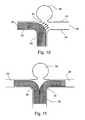
- FIG. 11shows another embodiment in which aneurysm sac 34 occupies the basal apex of bifurcation of source blood vessel 32 into first branch vessel 36 and second branch vessel 38 .
- Two mesh-like tube devices 30are inserted through blood vessel 32 into branch vessels 36 and 38 , respectively and are expanded to their implanted state thus being securely embedded against the walls of source blood vessel 32 , and branch vessels 36 and 38 , respectively.
- both mesh-like tube devices 30are of the self-expanding type.
- mesh-like tube devices 30are a braided self-expanding type. The P.I. is selected to skew the blood flow away from aneurysm sack 34 .
- mesh-like tube devices 30do not directly overly aneurysm sac 34 .
- FIG. 12shows another embodiment in which aneurysm sac 34 occupies the basal apex of bifurcation of blood vessel 32 into first branch vessel 36 and second branch vessel 38 .
- a mesh-like tube device 30is inserted through source blood vessel 32 into branch vessel 36 and expanded to its implanted state thereby being securely embedded against source blood vessel 32 and branch vessel 36 .
- a mesh-like tube device 50is inserted through mesh-like tube device 30 into branch vessel 38 and is expanded to its implanted state thus being securely embedded against the walls of source blood vessel 32 and branch vessel 38 .
- mesh-like tube devices 30 and 50are of the self-expanding type.
- mesh-like tube devices 30 and 50are a braided self-expanding type.
- Reducing the PI of braided tube device 30 to 74%increased the skew of the blood flow near aneurysm 34 to approximately 55° from the axis of blood vessel 32 .
- a reduced PIsuccessfully skewed the blood flow from directly impacting aneurysm 34 .
- the devicecould be composed of multiple tubular meshes, lying one above the other in layer-like formations.
- the devicecould include a plurality of groups of filaments in the longitudinal and/or circumferential direction.
- the inventioncould be implemented with respect to many of the other variations and applications described in the above-cited International Application PCT/IL01/00624, equivalent to U.S. patent application Ser. No. 10/311,876, published as U.S. Patent Application Publication No. 2004/0024416 incorporated herein by reference.
Landscapes
- Health & Medical Sciences (AREA)
- Engineering & Computer Science (AREA)
- Biomedical Technology (AREA)
- Cardiology (AREA)
- Oral & Maxillofacial Surgery (AREA)
- Transplantation (AREA)
- Heart & Thoracic Surgery (AREA)
- Vascular Medicine (AREA)
- Life Sciences & Earth Sciences (AREA)
- Animal Behavior & Ethology (AREA)
- General Health & Medical Sciences (AREA)
- Public Health (AREA)
- Veterinary Medicine (AREA)
- Gastroenterology & Hepatology (AREA)
- Pulmonology (AREA)
- Prostheses (AREA)
- Media Introduction/Drainage Providing Device (AREA)
- Surgical Instruments (AREA)
Abstract
Description
- 1. Placement of embolic material, such as metallic microcoils or spherical beads, inside the aneurysm sac in order to form a mass within this sac which will slow the blood flow and generally encourage the aneurysm to clot off and to shrink. To accomplish this procedure, a microcatheter is guided through the cerebral arteries until the site of the aneurysm is reached. The distal tip of the microcatheter is then placed within the sac of the aneurysm, and the embolic material is injected into the sac of the aneurysm. Typical microcatheters suitable for this procedure are disclosed in U.S. Pat. Nos. 5,853,418; 6,066,133; 6,165,198 and 6,168,592.
- 2. Another endovascular technique for treating aneurysms involves inserting a detachable balloon into the sac of the aneurysm using a microcatheter. The detachable balloon is then inflated using embolic material, such as a liquid polymer material or microcoils. The balloon is then detached from the microcatheter and left within the sac of the aneurysm in an attempt to fill the sac and to form a thrombotic mass inside the aneurysm.
- 3. Stent technology has been applied to the intracranial vasculature. The use of this technology has been limited until recently by the lack of available stents and stent delivery systems capable of safe and effective navigation through the intercranial vessels. The use of such stents is particularly difficult with respect to aneurysms in head blood vessels because of the number of perforating vessels in such blood vessels, and thereby the increased danger that one or more perforating vessels may be in the vicinity of such an aneurysm. The same is true with respect to bifurcations of a blood vessel splitting into one or more branch vessels, which may also be in the vicinity of an aneurysm. Where the blood supply to an aneurysm is to be reduced, it is critical that the blood supply to such perforating vessel or branch vessels, in the vicinity of the aneurysm not be unduly reduced to the degree causing damage to the tissues supplied with blood by such perforating or branch vessels.
- 1. An International Study of Unruptured Intracranial Aneurysms Investigators. N Engl J. Med. 1998 Dec. 10; 339(24):1725-33: International study of unruptured intracranial aneurysms investigators; Unruptured intracranial aneurysms—risk of rupture and risks of surgical intervention.
- 2. Bederson J B, Awad I A, Wiebers D O, Piepgras D, Haley E C Jr, Brott T, Hademenos G, Chyatte D, Rosenwasser R, Caroselli C.; Recommendations for the management of patients with unruptured intracranial aneurysms: A Statement for healthcare professionals from the Stroke Council of the American Heart Association. Stroke. 2000 November; 31(11): 2742-50. No abstract available.
- 3. Wardlaw J M, White P M. The detection and management of unruptured intracranial aneurysms. Brain. 2000 February; 123 (Pt 2):205-21. Review.
- 4. Wakhloo A K, Lanzino G, Lieber B B, Hopkins L N. Stents for intracranial aneurysms: the beginning of a new endovascular era? Neurosurgery. 1998 August; 43(2): 377-9.
- 5. Lieber B B, Stancampiano A P, Wakhloo A K. Alteration of hemodynamics in aneurysm models by stenting: influence of stent porosity. Ann Biomed Eng. 1997 May-June; 25(3):460-9.
- 6. Lanzino G, Wakhloo A K, Fessler R D, Hartney M L, Guterman L R, Hopkins L N. Efficacy and current limitations of intravascular stents for intracranial internal carotid, vertebral, and basilar artery aneurysms. J. Neurosurg. 1999 October; 91(4): 538-46.
- 7. Yu S C, Zhao J B. A steady flow analysis on the stented and non-stented sidewall aneurysm models. Med Eng Phys. 1999 April; 21(3):133-41.
- 8. Marinkovic S, Gibo H, Milisavljevic M, Cetkovic M. Anatomic and clinical correlations of the lenticulostriate arteries. Clin Anat. 2001 May; 14(3):190-5.
Claims (28)
Priority Applications (1)
| Application Number | Priority Date | Filing Date | Title |
|---|---|---|---|
| US12/709,483US8419787B2 (en) | 2001-11-23 | 2010-02-21 | Implantable intraluminal device and method of using same in treating aneurysms |
Applications Claiming Priority (6)
| Application Number | Priority Date | Filing Date | Title |
|---|---|---|---|
| US33201301P | 2001-11-23 | 2001-11-23 | |
| US10/216,356US20030100945A1 (en) | 2001-11-23 | 2002-08-12 | Implantable intraluminal device and method of using same in treating aneurysms |
| US10/910,621US7306624B2 (en) | 2001-07-09 | 2004-08-04 | Implantable intraluminal device and method of using same in treating aneurysms |
| US11/907,675US7572290B2 (en) | 2001-07-09 | 2007-10-16 | Implantable intraluminal device and method of using same in treating aneurysms |
| US12/496,672US7942925B2 (en) | 2001-07-09 | 2009-07-02 | Implantable intraluminal device and method of using same in treating aneurysms |
| US12/709,483US8419787B2 (en) | 2001-11-23 | 2010-02-21 | Implantable intraluminal device and method of using same in treating aneurysms |
Related Parent Applications (1)
| Application Number | Title | Priority Date | Filing Date |
|---|---|---|---|
| US12/496,672ContinuationUS7942925B2 (en) | 2001-07-09 | 2009-07-02 | Implantable intraluminal device and method of using same in treating aneurysms |
Publications (2)
| Publication Number | Publication Date |
|---|---|
| US20100198334A1 US20100198334A1 (en) | 2010-08-05 |
| US8419787B2true US8419787B2 (en) | 2013-04-16 |
Family
ID=26910931
Family Applications (5)
| Application Number | Title | Priority Date | Filing Date |
|---|---|---|---|
| US10/216,356AbandonedUS20030100945A1 (en) | 2001-07-09 | 2002-08-12 | Implantable intraluminal device and method of using same in treating aneurysms |
| US10/910,621Expired - LifetimeUS7306624B2 (en) | 2001-07-09 | 2004-08-04 | Implantable intraluminal device and method of using same in treating aneurysms |
| US11/907,675Expired - LifetimeUS7572290B2 (en) | 2001-07-09 | 2007-10-16 | Implantable intraluminal device and method of using same in treating aneurysms |
| US12/496,672Expired - Fee RelatedUS7942925B2 (en) | 2001-07-09 | 2009-07-02 | Implantable intraluminal device and method of using same in treating aneurysms |
| US12/709,483Expired - Fee RelatedUS8419787B2 (en) | 2001-11-23 | 2010-02-21 | Implantable intraluminal device and method of using same in treating aneurysms |
Family Applications Before (4)
| Application Number | Title | Priority Date | Filing Date |
|---|---|---|---|
| US10/216,356AbandonedUS20030100945A1 (en) | 2001-07-09 | 2002-08-12 | Implantable intraluminal device and method of using same in treating aneurysms |
| US10/910,621Expired - LifetimeUS7306624B2 (en) | 2001-07-09 | 2004-08-04 | Implantable intraluminal device and method of using same in treating aneurysms |
| US11/907,675Expired - LifetimeUS7572290B2 (en) | 2001-07-09 | 2007-10-16 | Implantable intraluminal device and method of using same in treating aneurysms |
| US12/496,672Expired - Fee RelatedUS7942925B2 (en) | 2001-07-09 | 2009-07-02 | Implantable intraluminal device and method of using same in treating aneurysms |
Country Status (6)
| Country | Link |
|---|---|
| US (5) | US20030100945A1 (en) |
| EP (2) | EP1455679B1 (en) |
| AU (1) | AU2002349793A1 (en) |
| ES (2) | ES2401426T3 (en) |
| IL (1) | IL162088A0 (en) |
| WO (1) | WO2003043527A2 (en) |
Cited By (13)
| Publication number | Priority date | Publication date | Assignee | Title |
|---|---|---|---|---|
| US8715317B1 (en) | 2013-07-29 | 2014-05-06 | Insera Therapeutics, Inc. | Flow diverting devices |
| US8721676B1 (en) | 2013-03-15 | 2014-05-13 | Insera Therapeutics, Inc. | Slotted vascular treatment devices |
| US9034007B2 (en) | 2007-09-21 | 2015-05-19 | Insera Therapeutics, Inc. | Distal embolic protection devices with a variable thickness microguidewire and methods for their use |
| US9179931B2 (en) | 2013-03-15 | 2015-11-10 | Insera Therapeutics, Inc. | Shape-set textile structure based mechanical thrombectomy systems |
| US9314324B2 (en) | 2013-03-15 | 2016-04-19 | Insera Therapeutics, Inc. | Vascular treatment devices and methods |
| US9358140B1 (en) | 2009-11-18 | 2016-06-07 | Aneuclose Llc | Stent with outer member to embolize an aneurysm |
| US10028747B2 (en) | 2008-05-01 | 2018-07-24 | Aneuclose Llc | Coils with a series of proximally-and-distally-connected loops for occluding a cerebral aneurysm |
| US10390926B2 (en) | 2013-07-29 | 2019-08-27 | Insera Therapeutics, Inc. | Aspiration devices and methods |
| US10716573B2 (en) | 2008-05-01 | 2020-07-21 | Aneuclose | Janjua aneurysm net with a resilient neck-bridging portion for occluding a cerebral aneurysm |
| US11013833B2 (en) | 2015-08-03 | 2021-05-25 | Advanced Endovascular Therapeutics | Coatings for medical devices |
| US11291566B2 (en) | 2010-12-13 | 2022-04-05 | Terumo Corporation | Stent |
| US11564819B2 (en) | 2012-03-16 | 2023-01-31 | Terumo Corporation | Stent and stent delivery device |
| US12419764B2 (en) | 2018-03-12 | 2025-09-23 | Fluid Biomed Inc. | Bioabsorbable flow diverting scaffold |
Families Citing this family (157)
| Publication number | Priority date | Publication date | Assignee | Title |
|---|---|---|---|---|
| US20030100945A1 (en)* | 2001-11-23 | 2003-05-29 | Mindguard Ltd. | Implantable intraluminal device and method of using same in treating aneurysms |
| US7147661B2 (en) | 2001-12-20 | 2006-12-12 | Boston Scientific Santa Rosa Corp. | Radially expandable stent |
| US6866679B2 (en) | 2002-03-12 | 2005-03-15 | Ev3 Inc. | Everting stent and stent delivery system |
| US20100196345A1 (en)* | 2003-04-27 | 2010-08-05 | Protalix | Production of high mannose proteins in plant culture |
| US7951557B2 (en)* | 2003-04-27 | 2011-05-31 | Protalix Ltd. | Human lysosomal proteins from plant cell culture |
| DE10335649A1 (en)* | 2003-07-30 | 2005-02-24 | Jotec Gmbh | Braid stent for implantation in a blood vessel |
| DE10351220A1 (en)* | 2003-10-28 | 2005-06-02 | Deutsche Institute für Textil- und Faserforschung Stuttgart - Stiftung des öffentlichen Rechts | Tubular implant |
| US8715340B2 (en)* | 2004-03-31 | 2014-05-06 | Merlin Md Pte Ltd. | Endovascular device with membrane |
| WO2005094725A1 (en)* | 2004-03-31 | 2005-10-13 | Merlin Md Pte Ltd | A method for treating aneurysms |
| US8500751B2 (en)* | 2004-03-31 | 2013-08-06 | Merlin Md Pte Ltd | Medical device |
| US20060206200A1 (en) | 2004-05-25 | 2006-09-14 | Chestnut Medical Technologies, Inc. | Flexible vascular occluding device |
| CA2758946C (en) | 2004-05-25 | 2014-10-21 | Tyco Healthcare Group Lp | Vascular stenting for aneurysms |
| CA2565106C (en) | 2004-05-25 | 2013-11-05 | Chestnut Medical Technologies, Inc. | Flexible vascular occluding device |
| US8617234B2 (en)* | 2004-05-25 | 2013-12-31 | Covidien Lp | Flexible vascular occluding device |
| US8623067B2 (en) | 2004-05-25 | 2014-01-07 | Covidien Lp | Methods and apparatus for luminal stenting |
| US8267985B2 (en) | 2005-05-25 | 2012-09-18 | Tyco Healthcare Group Lp | System and method for delivering and deploying an occluding device within a vessel |
| US20060206198A1 (en)* | 2005-03-12 | 2006-09-14 | Churchwell Stacey D | Aneurysm treatment devices and methods |
| US20060206199A1 (en)* | 2005-03-12 | 2006-09-14 | Churchwell Stacey D | Aneurysm treatment devices |
| US8961586B2 (en) | 2005-05-24 | 2015-02-24 | Inspiremd Ltd. | Bifurcated stent assemblies |
| US8043323B2 (en) | 2006-10-18 | 2011-10-25 | Inspiremd Ltd. | In vivo filter assembly |
| CA2609687C (en) | 2005-05-24 | 2014-04-22 | Inspire M.D Ltd. | Stent apparatuses for treatment via body lumens and methods of use |
| US8273101B2 (en) | 2005-05-25 | 2012-09-25 | Tyco Healthcare Group Lp | System and method for delivering and deploying an occluding device within a vessel |
| AU2005332044B2 (en)* | 2005-05-25 | 2012-01-19 | Covidien Lp | System and method for delivering and deploying and occluding device within a vessel |
| US20070060994A1 (en)* | 2005-09-12 | 2007-03-15 | Gobran Riad H | Blood flow diverters for the treatment of intracranial aneurysms |
| US20090054966A1 (en)* | 2006-02-13 | 2009-02-26 | Merlin Md Pte Ltd. | Endovascular device with membrane |
| US8152833B2 (en) | 2006-02-22 | 2012-04-10 | Tyco Healthcare Group Lp | Embolic protection systems having radiopaque filter mesh |
| US20080033341A1 (en)* | 2006-08-04 | 2008-02-07 | Bay Holdings Ltd. | Methods and devices for reducing or blocking blood flow to a selected blood vessel or part thereof |
| CA2660851A1 (en)* | 2006-08-17 | 2008-02-21 | Nfocus Neuromedical, Inc. | Isolation devices for the treatment of aneurysms |
| US20100324664A1 (en)* | 2006-10-18 | 2010-12-23 | Asher Holzer | Bifurcated Stent Assemblies |
| WO2008047369A2 (en)* | 2006-10-18 | 2008-04-24 | Inspiremd Ltd. | Knitted stent jackets |
| GB0621048D0 (en)* | 2006-10-23 | 2006-11-29 | Anson Medical Ltd | Helical stent graft |
| US9622888B2 (en) | 2006-11-16 | 2017-04-18 | W. L. Gore & Associates, Inc. | Stent having flexibly connected adjacent stent elements |
| EP3292837B1 (en) | 2006-11-22 | 2022-11-09 | Inspire M.D Ltd | Optimized stent jacket |
| DE102007012964A1 (en) | 2007-03-06 | 2008-09-11 | Phenox Gmbh | Implant for influencing blood flow |
| WO2008135991A2 (en)* | 2007-05-07 | 2008-11-13 | Protalix Ltd. | Large scale disposable bioreactor |
| US20110022149A1 (en) | 2007-06-04 | 2011-01-27 | Cox Brian J | Methods and devices for treatment of vascular defects |
| US20080319533A1 (en)* | 2007-06-22 | 2008-12-25 | Neurovasx, Inc. | Aneurysm occlusion assist device |
| US20090082803A1 (en) | 2007-09-26 | 2009-03-26 | Aga Medical Corporation | Braided vascular devices having no end clamps |
| WO2009076515A1 (en) | 2007-12-11 | 2009-06-18 | Cornell University | Method and apparatus for sealing an opening in the side wall of a body lumen |
| US8926688B2 (en) | 2008-01-11 | 2015-01-06 | W. L. Gore & Assoc. Inc. | Stent having adjacent elements connected by flexible webs |
| EP2633823B1 (en)* | 2008-04-21 | 2016-06-01 | Covidien LP | Braid-ball embolic devices and delivery systems |
| US8974487B2 (en) | 2008-05-01 | 2015-03-10 | Aneuclose Llc | Aneurysm occlusion device |
| AU2009242528B2 (en)* | 2008-05-02 | 2015-12-10 | Microvention, Inc. | Filamentary devices for treatment of vascular defects |
| WO2009140437A1 (en) | 2008-05-13 | 2009-11-19 | Nfocus Neuromedical, Inc. | Braid implant delivery systems |
| US8401681B2 (en)* | 2008-06-08 | 2013-03-19 | Apple Inc. | System and method for placeshifting media playback |
| US9179918B2 (en)* | 2008-07-22 | 2015-11-10 | Covidien Lp | Vascular remodeling device |
| US20100063578A1 (en) | 2008-09-05 | 2010-03-11 | Aga Medical Corporation | Bifurcated medical device for treating a target site and associated method |
| US20100131002A1 (en)* | 2008-11-24 | 2010-05-27 | Connor Robert A | Stent with a net layer to embolize and aneurysm |
| JP5750051B2 (en) | 2009-01-22 | 2015-07-15 | コーネル ユニヴァーシティー | Method and apparatus for restricting flow through a lumen wall |
| CA2753853C (en) | 2009-03-06 | 2017-04-25 | Daniel S. Levi | Thin film vascular stent and biocompatible surface treatment |
| BRPI1014915A2 (en)* | 2009-04-17 | 2016-04-26 | Tyco Healthcare | vascular stent implantation for aneurysms |
| US8409269B2 (en) | 2009-12-21 | 2013-04-02 | Covidien Lp | Procedures for vascular occlusion |
| CN101991477B (en)* | 2009-08-27 | 2014-03-26 | 上海微创医疗器械(集团)有限公司 | Vascular reconstructive support frame |
| US20110087252A1 (en) | 2009-10-08 | 2011-04-14 | Wilson-Cook Medical Inc. | Biliary decompression and anastomosis stent |
| BR112012010758A2 (en) | 2009-11-05 | 2019-09-24 | Sequent Medical Inc | multilayer filament devices for treatment of vascular defects |
| US9095342B2 (en) | 2009-11-09 | 2015-08-04 | Covidien Lp | Braid ball embolic device features |
| US8906057B2 (en) | 2010-01-04 | 2014-12-09 | Aneuclose Llc | Aneurysm embolization by rotational accumulation of mass |
| JP4499831B1 (en)* | 2010-01-22 | 2010-07-07 | 規方 田熊 | Aneurysm embolizer |
| WO2011094638A1 (en)* | 2010-01-28 | 2011-08-04 | Micro Therapeutics, Inc. | Vascular remodeling device |
| WO2011094634A1 (en)* | 2010-01-28 | 2011-08-04 | Micro Therapeutics, Inc. | Vascular remodeling device |
| WO2011150118A2 (en) | 2010-05-25 | 2011-12-01 | The Regents Of The University Of California | Ultra-low fractional area coverage flow diverter for treating aneurysms and vascular diseases |
| US8425548B2 (en) | 2010-07-01 | 2013-04-23 | Aneaclose LLC | Occluding member expansion and then stent expansion for aneurysm treatment |
| JP5868432B2 (en) | 2011-02-11 | 2016-02-24 | コヴィディエン リミテッド パートナーシップ | Two-stage deployed aneurysm embolization device |
| US20120245674A1 (en) | 2011-03-25 | 2012-09-27 | Tyco Healthcare Group Lp | Vascular remodeling device |
| WO2012135859A2 (en) | 2011-04-01 | 2012-10-04 | Cornell University | Method and apparatus for restricting flow through an opening in the side wall of a body lumen, and/or for reinforcing a weakness in the side wall of a body lumen, while still maintaining substantially normal flow through the body lumen |
| CN103547222B (en) | 2011-05-11 | 2016-02-10 | 柯惠有限合伙公司 | Vascular remodeling device |
| US9138232B2 (en) | 2011-05-24 | 2015-09-22 | Aneuclose Llc | Aneurysm occlusion by rotational dispensation of mass |
| KR101480514B1 (en)* | 2011-05-26 | 2015-01-09 | 재단법인 아산사회복지재단 | Stent for cerebral aneurysm coil embolization |
| US9060886B2 (en) | 2011-09-29 | 2015-06-23 | Covidien Lp | Vascular remodeling device |
| EP2763601B1 (en) | 2011-10-07 | 2020-03-25 | Cornell University | Apparatus for restricting flow through an opening in a body lumen while maintaining normal flow |
| US8771341B2 (en) | 2011-11-04 | 2014-07-08 | Reverse Medical Corporation | Protuberant aneurysm bridging device and method of use |
| US9072620B2 (en) | 2011-11-04 | 2015-07-07 | Covidien Lp | Protuberant aneurysm bridging device deployment method |
| AU2013221777B2 (en)* | 2012-02-13 | 2016-10-13 | Board Of Regents, The University Of Texas System | Scaffold system for tissue repair |
| US9072624B2 (en) | 2012-02-23 | 2015-07-07 | Covidien Lp | Luminal stenting |
| US20130226278A1 (en) | 2012-02-23 | 2013-08-29 | Tyco Healthcare Group Lp | Methods and apparatus for luminal stenting |
| US9005270B2 (en) | 2012-03-27 | 2015-04-14 | Medtronic Vascular, Inc. | High metal to vessel ratio stent and method |
| US8911490B2 (en) | 2012-03-27 | 2014-12-16 | Medtronic Vascular, Inc. | Integrated mesh high metal to vessel ratio stent and method |
| US9393136B2 (en) | 2012-03-27 | 2016-07-19 | Medtronic Vascular, Inc. | Variable zone high metal to vessel ratio stent and method |
| US10987208B2 (en) | 2012-04-06 | 2021-04-27 | Merlin Md Pte Ltd. | Devices and methods for treating an aneurysm |
| US9078659B2 (en) | 2012-04-23 | 2015-07-14 | Covidien Lp | Delivery system with hooks for resheathability |
| EP2854700B1 (en) | 2012-05-31 | 2021-07-07 | Javelin Medical Ltd. | Devices for embolic protection |
| WO2014111911A1 (en)* | 2013-01-18 | 2014-07-24 | Javelin Medical Ltd. | Monofilament implants and systems for delivery thereof |
| US9155647B2 (en) | 2012-07-18 | 2015-10-13 | Covidien Lp | Methods and apparatus for luminal stenting |
| US9724222B2 (en) | 2012-07-20 | 2017-08-08 | Covidien Lp | Resheathable stent delivery system |
| US9301831B2 (en) | 2012-10-30 | 2016-04-05 | Covidien Lp | Methods for attaining a predetermined porosity of a vascular device |
| US9452070B2 (en) | 2012-10-31 | 2016-09-27 | Covidien Lp | Methods and systems for increasing a density of a region of a vascular device |
| US9943427B2 (en) | 2012-11-06 | 2018-04-17 | Covidien Lp | Shaped occluding devices and methods of using the same |
| US9314248B2 (en) | 2012-11-06 | 2016-04-19 | Covidien Lp | Multi-pivot thrombectomy device |
| US20140180377A1 (en)* | 2012-12-20 | 2014-06-26 | Penumbra, Inc. | Aneurysm occlusion system and method |
| US9295571B2 (en) | 2013-01-17 | 2016-03-29 | Covidien Lp | Methods and apparatus for luminal stenting |
| US9157174B2 (en) | 2013-02-05 | 2015-10-13 | Covidien Lp | Vascular device for aneurysm treatment and providing blood flow into a perforator vessel |
| US20140257362A1 (en)* | 2013-03-07 | 2014-09-11 | St. Jude Medical, Cardiology Division, Inc. | Filtering and removing particulates from bloodstream |
| EP2967824B1 (en) | 2013-03-12 | 2020-11-04 | Carnegie Mellon University | Coated vaso-occlusive device for treatment of aneurysms |
| US20140277397A1 (en) | 2013-03-12 | 2014-09-18 | DePuy Synthes Products, LLC | Variable porosity intravascular implant and manufacturing method |
| US10561509B2 (en) | 2013-03-13 | 2020-02-18 | DePuy Synthes Products, Inc. | Braided stent with expansion ring and method of delivery |
| US9463105B2 (en) | 2013-03-14 | 2016-10-11 | Covidien Lp | Methods and apparatus for luminal stenting |
| US9545301B2 (en) | 2013-03-15 | 2017-01-17 | Covidien Lp | Coated medical devices and methods of making and using same |
| US10736758B2 (en) | 2013-03-15 | 2020-08-11 | Covidien | Occlusive device |
| US9320592B2 (en)* | 2013-03-15 | 2016-04-26 | Covidien Lp | Coated medical devices and methods of making and using same |
| US9907684B2 (en) | 2013-05-08 | 2018-03-06 | Aneuclose Llc | Method of radially-asymmetric stent expansion |
| GB2514135B (en) | 2013-05-14 | 2015-04-15 | Cook Medical Technologies Llc | Implantable flow diverter |
| US20160151141A1 (en)* | 2013-07-17 | 2016-06-02 | Lake Region Manufacturing, Inc. | High Flow Embolic Protection Device |
| US10130500B2 (en) | 2013-07-25 | 2018-11-20 | Covidien Lp | Methods and apparatus for luminal stenting |
| GB2519932B (en) | 2013-08-13 | 2015-10-21 | Cook Medical Technologies Llc | Implantable flow adjuster |
| US9078658B2 (en) | 2013-08-16 | 2015-07-14 | Sequent Medical, Inc. | Filamentary devices for treatment of vascular defects |
| US9955976B2 (en) | 2013-08-16 | 2018-05-01 | Sequent Medical, Inc. | Filamentary devices for treatment of vascular defects |
| US10045867B2 (en) | 2013-08-27 | 2018-08-14 | Covidien Lp | Delivery of medical devices |
| US9782186B2 (en) | 2013-08-27 | 2017-10-10 | Covidien Lp | Vascular intervention system |
| US9668890B2 (en) | 2013-11-22 | 2017-06-06 | Covidien Lp | Anti-thrombogenic medical devices and methods |
| US9592110B1 (en) | 2013-12-06 | 2017-03-14 | Javelin Medical, Ltd. | Systems and methods for implant delivery |
| JP6661539B2 (en) | 2013-12-20 | 2020-03-11 | テルモ株式会社 | Vessel closure |
| US9629635B2 (en) | 2014-04-14 | 2017-04-25 | Sequent Medical, Inc. | Devices for therapeutic vascular procedures |
| EP3177237A4 (en) | 2014-08-07 | 2018-03-14 | Perflow Medical Ltd. | Aneurysm treatment device and method |
| US10206796B2 (en) | 2014-08-27 | 2019-02-19 | DePuy Synthes Products, Inc. | Multi-strand implant with enhanced radiopacity |
| US10299948B2 (en) | 2014-11-26 | 2019-05-28 | W. L. Gore & Associates, Inc. | Balloon expandable endoprosthesis |
| US9789228B2 (en) | 2014-12-11 | 2017-10-17 | Covidien Lp | Antimicrobial coatings for medical devices and processes for preparing such coatings |
| US11147699B2 (en) | 2015-07-24 | 2021-10-19 | Route 92 Medical, Inc. | Methods of intracerebral implant delivery |
| CA2995407A1 (en)* | 2015-09-09 | 2017-03-16 | Frid Mind Technologies | Bifurcated 3d filter assembly for prevention of stroke |
| US10478194B2 (en) | 2015-09-23 | 2019-11-19 | Covidien Lp | Occlusive devices |
| US10568752B2 (en) | 2016-05-25 | 2020-02-25 | W. L. Gore & Associates, Inc. | Controlled endoprosthesis balloon expansion |
| WO2018017981A1 (en)* | 2016-07-22 | 2018-01-25 | Route 92 Medical, Inc. | Endovascular interventions in neurovascular anatomy |
| US10076428B2 (en) | 2016-08-25 | 2018-09-18 | DePuy Synthes Products, Inc. | Expansion ring for a braided stent |
| US10292851B2 (en) | 2016-09-30 | 2019-05-21 | DePuy Synthes Products, Inc. | Self-expanding device delivery apparatus with dual function bump |
| EP4331536A3 (en) | 2016-10-21 | 2024-05-22 | Javelin Medical Ltd. | Systems, methods and devices for embolic protection |
| US10376396B2 (en) | 2017-01-19 | 2019-08-13 | Covidien Lp | Coupling units for medical device delivery systems |
| US11191976B2 (en) | 2017-05-19 | 2021-12-07 | Prometheus Therapeutics Inc. | Devices and methods for repair of a selected blood vessel or part thereof and rapid healing of injured internal body cavity walls |
| EP3629945A4 (en) | 2017-05-25 | 2021-03-03 | Terumo Corporation | ADHESIVE LOCKING SYSTEMS |
| US11103252B2 (en)* | 2018-01-23 | 2021-08-31 | Swaminathan Jayaraman | Device to treat vascular defect and method of making the same |
| US11065009B2 (en)* | 2018-02-08 | 2021-07-20 | Covidien Lp | Vascular expandable devices |
| US11065136B2 (en)* | 2018-02-08 | 2021-07-20 | Covidien Lp | Vascular expandable devices |
| CN108210134B (en)* | 2018-02-27 | 2024-05-10 | 北京航空航天大学 | Vascular stent |
| US10786377B2 (en) | 2018-04-12 | 2020-09-29 | Covidien Lp | Medical device delivery |
| US11413176B2 (en) | 2018-04-12 | 2022-08-16 | Covidien Lp | Medical device delivery |
| US11071637B2 (en) | 2018-04-12 | 2021-07-27 | Covidien Lp | Medical device delivery |
| US11123209B2 (en) | 2018-04-12 | 2021-09-21 | Covidien Lp | Medical device delivery |
| AU2019204522A1 (en) | 2018-07-30 | 2020-02-13 | DePuy Synthes Products, Inc. | Systems and methods of manufacturing and using an expansion ring |
| US10278848B1 (en) | 2018-08-06 | 2019-05-07 | DePuy Synthes Products, Inc. | Stent delivery with expansion assisting delivery wire |
| US10456280B1 (en) | 2018-08-06 | 2019-10-29 | DePuy Synthes Products, Inc. | Systems and methods of using a braided implant |
| WO2020093012A1 (en) | 2018-11-01 | 2020-05-07 | Terumo Corporation | Occlusion systems |
| US11039944B2 (en) | 2018-12-27 | 2021-06-22 | DePuy Synthes Products, Inc. | Braided stent system with one or more expansion rings |
| CN113573765B (en) | 2019-03-15 | 2024-08-13 | 美科微先股份有限公司 | Silk device for treating vascular defects |
| CN113573650B (en) | 2019-03-15 | 2024-05-28 | 后续医疗股份有限公司 | Silk device with flexible connector for treating vascular defects |
| US11559309B2 (en) | 2019-03-15 | 2023-01-24 | Sequent Medical, Inc. | Filamentary devices for treatment of vascular defects |
| CN110025414B (en)* | 2019-04-16 | 2021-07-20 | 吉林大学中日联谊医院 | Braided vascular stent and preparation method thereof |
| US11413174B2 (en) | 2019-06-26 | 2022-08-16 | Covidien Lp | Core assembly for medical device delivery systems |
| US12070220B2 (en) | 2020-03-11 | 2024-08-27 | Microvention, Inc. | Devices having multiple permeable shells for treatment of vascular defects |
| US20210282789A1 (en) | 2020-03-11 | 2021-09-16 | Microvention, Inc. | Multiple layer devices for treatment of vascular defects |
| US12023034B2 (en) | 2020-03-11 | 2024-07-02 | Microvention, Inc. | Devices for treatment of vascular defects |
| CA3175525A1 (en) | 2020-04-28 | 2021-11-04 | Terumo Corporation | Occlusion systems |
| CN113967113B (en)* | 2020-07-06 | 2023-05-16 | 上海启功医疗科技有限公司 | Support, support external member and support delivery system |
| CN113893071B (en)* | 2020-07-06 | 2025-03-11 | 上海启功医疗科技有限公司 | A bare stent compressible in the axial direction |
| CN113893070B (en)* | 2020-07-06 | 2025-03-18 | 上海启功医疗科技有限公司 | A bare stent that can be compressed and stretched along the axial direction |
| CN113967114B (en)* | 2020-07-22 | 2025-09-16 | 上海启功医疗科技有限公司 | Quick aortic repair stent, stent kit and delivery system |
| US12042413B2 (en) | 2021-04-07 | 2024-07-23 | Covidien Lp | Delivery of medical devices |
| US12109137B2 (en) | 2021-07-30 | 2024-10-08 | Covidien Lp | Medical device delivery |
| US11944558B2 (en) | 2021-08-05 | 2024-04-02 | Covidien Lp | Medical device delivery devices, systems, and methods |
| CN117898867A (en)* | 2022-12-02 | 2024-04-19 | 上海励楷科技有限公司 | Braided stent |
Citations (186)
| Publication number | Priority date | Publication date | Assignee | Title |
|---|---|---|---|---|
| US467993A (en) | 1892-02-02 | Alfred jorgensen | ||
| US2147271A (en) | 1937-07-16 | 1939-02-14 | Schwarz Lab Inc | Pure yeast culture apparatus |
| US2341259A (en) | 1941-01-22 | 1944-02-08 | Lummus Co | Inoculating method and apparatus |
| US2836434A (en) | 1952-08-21 | 1958-05-27 | Separator Ab | Arrangement for sterile interconnection and sealing of apparatuses in a plant for instance for cultivation of bacteria |
| US3201327A (en) | 1962-08-21 | 1965-08-17 | Sun Oil Co | Fermentation apparatus and process |
| US3468520A (en) | 1967-05-12 | 1969-09-23 | American Cyanamid Co | Combination agitation and transfer unit for suspended cells |
| US3504185A (en) | 1968-05-09 | 1970-03-31 | Univ Syracuse Res Corp | Apparatus for measuring and controlling cell population density in a liquid medium |
| US3540700A (en) | 1969-01-24 | 1970-11-17 | New Brunswick Scientific Co | Rotary processing apparatus |
| US3705082A (en) | 1968-10-18 | 1972-12-05 | British Petroleum Co | Cultivation and recovery of micro-organisms |
| US3743582A (en) | 1966-10-06 | 1973-07-03 | Sanraku Ocean Co | Method of fermentation utilizing a multi-stage fermenting device |
| US3793154A (en) | 1970-12-21 | 1974-02-19 | Univ St Johns | Apparatus for gaseous environmental control of batch cultures of micro-organisms |
| US3806423A (en) | 1970-12-05 | 1974-04-23 | Knapsack Ag | Method and apparatus for controlling foam formation in aeration reactors |
| US3950227A (en) | 1970-12-21 | 1976-04-13 | St. John's University | Batch method of establishing and maintaining a controlled aerobic environment for a microbial culture |
| DE2654725A1 (en) | 1975-12-02 | 1977-06-08 | Bioveta N P | UNIVERSAL SEPARATION BLOOD BAG FOR THE STERILE PREPARATION OF BLOOD SERUM FOR SINGLE USE |
| US4179339A (en) | 1977-03-02 | 1979-12-18 | Olympus Optical Company, Ltd. | Liquid feeder for automatic culture apparatus |
| US4228243A (en) | 1978-07-13 | 1980-10-14 | Toray Industries, Inc. | Cell culture propagation apparatus |
| US4328317A (en) | 1980-03-31 | 1982-05-04 | Solargizer International, Inc. | Continuous chemical conversion or fermentation apparatus |
| US4425908A (en) | 1981-10-22 | 1984-01-17 | Beth Israel Hospital | Blood clot filter |
| US4491549A (en) | 1981-08-22 | 1985-01-01 | Hoechst Aktiengesellschaft | Device for dispersing a second phase in a first phase |
| US4519984A (en) | 1982-01-18 | 1985-05-28 | Phillips Petroleum Company | Apparatus for carrying out sparged reaction |
| US4577631A (en) | 1984-11-16 | 1986-03-25 | Kreamer Jeffry W | Aneurysm repair apparatus and method |
| EP0183372A1 (en) | 1984-10-19 | 1986-06-04 | RAYCHEM CORPORATION (a Delaware corporation) | Prosthetic stent |
| US4619246A (en) | 1984-05-23 | 1986-10-28 | William Cook, Europe A/S | Collapsible filter basket |
| US4643184A (en) | 1982-09-29 | 1987-02-17 | Mobin Uddin Kazi | Embolus trap |
| US4655771A (en) | 1982-04-30 | 1987-04-07 | Shepherd Patents S.A. | Prosthesis comprising an expansible or contractile tubular body |
| US4668632A (en) | 1985-02-06 | 1987-05-26 | Vxr, Inc. | Sparger and apparatus for and method of growing cells |
| US4708938A (en) | 1984-04-30 | 1987-11-24 | Hickinbotham Winemakers Pty. Ltd. | Alcoholic fermentation |
| US4713345A (en) | 1985-07-29 | 1987-12-15 | Grain Processing Corporation | Fermentation methods and apparatus |
| US4717668A (en) | 1986-12-12 | 1988-01-05 | Baxter Travenol Laboratories, Inc. | Plastic roller bottle for suspension cultures |
| US4725548A (en) | 1982-05-27 | 1988-02-16 | Chemap Ag | Method and fermenter for growing tissue cells |
| US4760849A (en) | 1985-04-10 | 1988-08-02 | Medinvent S.A. | Planar blank and a coil spring manufactured therefrom |
| GB2202549A (en) | 1987-03-20 | 1988-09-28 | Philip John Whitney | Foldable fermenter |
| EP0343885A1 (en) | 1988-05-19 | 1989-11-29 | P.B. Ind. Plant Biotech Industries Ltd. | Air lift fermentor formed from flexible plastic sheets |
| US4888294A (en) | 1985-11-25 | 1989-12-19 | Nederlanden Vertegenwoordigd | Apparatus and method for the continuous cultivation of microorganisms in a culture liquid |
| US4908315A (en) | 1987-03-04 | 1990-03-13 | Agristar, Inc. | Integument and method for micropropagation and tissue culturing |
| EP0200792B1 (en) | 1985-02-01 | 1990-05-09 | Herbert Prof. Dr.-Ing. Märkl | Foil fermenter |
| US4931401A (en) | 1988-09-01 | 1990-06-05 | La Societe De Recherche Snc Inc. | Bioreactor |
| US5061275A (en) | 1986-04-21 | 1991-10-29 | Medinvent S.A. | Self-expanding prosthesis |
| US5073491A (en) | 1988-12-23 | 1991-12-17 | Hoffman-La Roche Inc. | Immobilization of cells in alginate beads containing cavities for growth of cells in airlift bioreactors |
| US5081036A (en) | 1987-01-23 | 1992-01-14 | Hoffmann-La Roche Inc. | Method and apparatus for cell culture |
| US5100801A (en) | 1989-01-26 | 1992-03-31 | Biocontrol Systems, Inc. | Device for sequential microbial enrichment in a single apparatus |
| US5166072A (en) | 1986-06-26 | 1992-11-24 | Bayer Aktiengesellschaft | Apparatus for the cultivation of immobilized micro-organisms |
| US5188946A (en) | 1989-01-26 | 1993-02-23 | Biocontrol Systems Incorporated | Process and device for sequential microbial enrichment in a single apparatus |
| US5225346A (en) | 1990-06-29 | 1993-07-06 | Sekisui Chemical Co., Ltd. | Culture bag |
| US5240598A (en) | 1990-09-18 | 1993-08-31 | Board Of Supervisors Of Louisiana State University And Agricultural And Mechanical College | Microbubble generator for the transfer of oxygen to microbial inocula and microbubble generator immobilized cell reactor |
| US5246855A (en) | 1991-01-16 | 1993-09-21 | Vogelbusch Gesellschaft M.B.H. | Reactor for carrying out biological reactions by means of biocatalysts |
| US5267791A (en) | 1991-12-13 | 1993-12-07 | Corning Incorporated | Suspended cell culture stirring vessel closure and apparatus |
| US5324304A (en) | 1992-06-18 | 1994-06-28 | William Cook Europe A/S | Introduction catheter set for a collapsible self-expandable implant |
| EP0350723B1 (en) | 1988-07-13 | 1994-08-10 | B. BRAUN BIOTECH INTERNATIONAL GmbH | Valve for connecting objects to container or ducts to be sterilised in situ |
| US5342781A (en) | 1993-07-15 | 1994-08-30 | Su Wei Wen W | External-loop perfusion air-lift bioreactor |
| US5350398A (en) | 1991-05-13 | 1994-09-27 | Dusan Pavcnik | Self-expanding filter for percutaneous insertion |
| US5367110A (en) | 1990-11-13 | 1994-11-22 | Yeda Research And Development Co. Ltd. | Transgenic plants overproducing threonine and lysine |
| US5372945A (en) | 1985-06-06 | 1994-12-13 | Alchas; Paul G. | Device and method for collecting and processing fat tissue and procuring microvessel endothelial cells to produce endothelial cell product |
| US5383392A (en) | 1993-03-16 | 1995-01-24 | Ward Holding Company, Inc. | Sheet registration control |
| US5409833A (en) | 1993-07-01 | 1995-04-25 | Baxter International Inc. | Microvessel cell isolation apparatus |
| US5415630A (en) | 1991-07-17 | 1995-05-16 | Gory; Pierre | Method for removably implanting a blood filter in a vein of the human body |
| US5443497A (en) | 1993-11-22 | 1995-08-22 | The Johns Hopkins University | Percutaneous prosthetic by-pass graft and method of use |
| US5456712A (en) | 1991-07-03 | 1995-10-10 | Maginot; Thomas J. | Graft and stent assembly |
| US5464449A (en) | 1993-07-08 | 1995-11-07 | Thomas J. Fogarty | Internal graft prosthesis and delivery system |
| US5534417A (en) | 1992-06-12 | 1996-07-09 | Ben-Gurion University Of The Negev | Microorganism growth apparatus |
| US5549892A (en) | 1988-12-23 | 1996-08-27 | Genzyme Corporation | Enhanced in vivo uptake of glucocerebrosidase |
| US5549626A (en) | 1994-12-23 | 1996-08-27 | New York Society For The Ruptured And Crippled Maintaining The Hospital For Special Surgery | Vena caval filter |
| US5562725A (en) | 1992-09-14 | 1996-10-08 | Meadox Medicals Inc. | Radially self-expanding implantable intraluminal device |
| US5565015A (en) | 1992-02-14 | 1996-10-15 | Kobayashi; Fumiko | Disposable fermenter and fermentation method |
| US5612188A (en) | 1991-11-25 | 1997-03-18 | Cornell Research Foundation, Inc. | Automated, multicompartmental cell culture system |
| US5725568A (en) | 1995-06-27 | 1998-03-10 | Scimed Life Systems, Inc. | Method and device for recanalizing and grafting arteries |
| US5769816A (en) | 1995-11-07 | 1998-06-23 | Embol-X, Inc. | Cannula with associated filter |
| US5800514A (en) | 1996-05-24 | 1998-09-01 | Meadox Medicals, Inc. | Shaped woven tubular soft-tissue prostheses and methods of manufacturing |
| US5807330A (en) | 1996-12-16 | 1998-09-15 | University Of Southern California | Angioplasty catheter |
| US5817126A (en) | 1997-03-17 | 1998-10-06 | Surface Genesis, Inc. | Compound stent |
| US5843089A (en) | 1990-12-28 | 1998-12-01 | Boston Scientific Corporation | Stent lining |
| US5843172A (en) | 1997-04-15 | 1998-12-01 | Advanced Cardiovascular Systems, Inc. | Porous medicated stent |
| US5853419A (en) | 1997-03-17 | 1998-12-29 | Surface Genesis, Inc. | Stent |
| US5855599A (en) | 1997-09-02 | 1999-01-05 | Sitek, Inc. | Silicon micro machined occlusion implant |
| US5871537A (en) | 1996-02-13 | 1999-02-16 | Scimed Life Systems, Inc. | Endovascular apparatus |
| US5876367A (en) | 1996-12-05 | 1999-03-02 | Embol-X, Inc. | Cerebral protection during carotid endarterectomy and downstream vascular protection during other surgeries |
| US5891191A (en) | 1996-04-30 | 1999-04-06 | Schneider (Usa) Inc | Cobalt-chromium-molybdenum alloy stent and stent-graft |
| US5922019A (en) | 1995-11-27 | 1999-07-13 | Schneider (Europe) A.G. | Conical stent |
| US5928260A (en) | 1997-07-10 | 1999-07-27 | Scimed Life Systems, Inc. | Removable occlusion system for aneurysm neck |
| US5928261A (en) | 1998-06-29 | 1999-07-27 | Ruiz; Carlos E. | Removable vascular filter, catheter system and methods of use |
| US5941896A (en) | 1997-09-08 | 1999-08-24 | Montefiore Hospital And Medical Center | Filter and method for trapping emboli during endovascular procedures |
| US5951599A (en) | 1997-07-09 | 1999-09-14 | Scimed Life Systems, Inc. | Occlusion system for endovascular treatment of an aneurysm |
| US5964798A (en) | 1997-12-16 | 1999-10-12 | Cardiovasc, Inc. | Stent having high radial strength |
| US5976169A (en) | 1997-12-16 | 1999-11-02 | Cardiovasc, Inc. | Stent with silver coating and method |
| US6022374A (en) | 1997-12-16 | 2000-02-08 | Cardiovasc, Inc. | Expandable stent having radiopaque marker and method |
| JP2000053549A (en) | 1998-08-06 | 2000-02-22 | Lotte Co Ltd | Agent for accelerating recalcification of dental enamel, composition for oral cavity, and food and drink |
| US6027529A (en) | 1997-04-15 | 2000-02-22 | Schneider (Usa) Inc | Protheses with selectively welded crossing strands |
| US6030414A (en) | 1997-11-13 | 2000-02-29 | Taheri; Syde A. | Variable stent and method for treatment of arterial disease |
| US6053932A (en) | 1997-03-06 | 2000-04-25 | Scimed Life Systems, Inc. | Distal protection device |
| US6054637A (en) | 1990-06-15 | 2000-04-25 | Novartis Finance Corporation | Signal sequences for vacuolar sorting |
| JP2000128752A (en) | 1998-10-20 | 2000-05-09 | Lotte Co Ltd | Tooth enamel recalcification promoter and composition for oral cavity and food/drink |
| US6071306A (en) | 1995-03-09 | 2000-06-06 | University Of Bristol | Externally stented vein segment and its use in an arteriovenous bypass grafting procedure |
| US6086577A (en) | 1997-08-13 | 2000-07-11 | Scimed Life Systems, Inc. | Detachable aneurysm neck bridge (III) |
| US6093199A (en) | 1998-08-05 | 2000-07-25 | Endovascular Technologies, Inc. | Intra-luminal device for treatment of body cavities and lumens and method of use |
| US6096546A (en) | 1998-01-30 | 2000-08-01 | Board Of Trustees, Rutgers, The State University Of New Jersey | Methods for recovering polypeptides from plants and portions thereof |
| US6146370A (en) | 1999-04-07 | 2000-11-14 | Coaxia, Inc. | Devices and methods for preventing distal embolization from the internal carotid artery using flow reversal by partial occlusion of the external carotid artery |
| US6190913B1 (en) | 1997-08-12 | 2001-02-20 | Vijay Singh | Method for culturing cells using wave-induced agitation |
| US6193748B1 (en) | 1997-02-12 | 2001-02-27 | Schneider (Usa) Inc | Occlusion device |
| US6193708B1 (en) | 1997-08-05 | 2001-02-27 | Scimed Life Systems, Inc. | Detachable aneurysm neck bridge (I) |
| US6258120B1 (en) | 1997-12-23 | 2001-07-10 | Embol-X, Inc. | Implantable cerebral protection device and methods of use |
| US6258115B1 (en) | 1997-04-23 | 2001-07-10 | Artemis Medical, Inc. | Bifurcated stent and distal protection system |
| US6261305B1 (en) | 1998-02-12 | 2001-07-17 | Eclips Systems Inc. | Endovascular prothesis with expandable leaf portion |
| US20010020175A1 (en) | 1998-06-16 | 2001-09-06 | Yuval Yassour | Implantable blood filtering device |
| US6309413B1 (en) | 1993-10-21 | 2001-10-30 | Corvita Corporation | Expandable supportive endoluminal grafts |
| US6312463B1 (en) | 2000-02-01 | 2001-11-06 | Endotex Interventional Systems, Inc. | Micro-porous mesh stent with hybrid structure |
| US6344052B1 (en) | 1999-09-27 | 2002-02-05 | World Medical Manufacturing Corporation | Tubular graft with monofilament fibers |
| US20020015708A1 (en) | 1999-01-04 | 2002-02-07 | Yehuda Stram | Recombinant vaccines against ibdv |
| US6348063B1 (en) | 1999-03-11 | 2002-02-19 | Mindguard Ltd. | Implantable stroke treating device |
| US6371980B1 (en) | 1999-08-30 | 2002-04-16 | Cardiovasc, Inc. | Composite expandable device with impervious polymeric covering and bioactive coating thereon, delivery apparatus and method |
| US6383171B1 (en) | 1999-10-12 | 2002-05-07 | Allan Will | Methods and devices for protecting a passageway in a body when advancing devices through the passageway |
| US6383174B1 (en) | 1997-08-05 | 2002-05-07 | Scimed Life Systems, Inc. | Detachable aneurysm neck bridge (II) |
| US6391638B1 (en) | 1996-09-26 | 2002-05-21 | Metabogal, Ltd. | Cell/tissue culturing device and method |
| US6409750B1 (en) | 1999-02-01 | 2002-06-25 | Board Of Regents, The University Of Texas System | Woven bifurcated and trifurcated stents and methods for making the same |
| US6409757B1 (en) | 1999-09-15 | 2002-06-25 | Eva Corporation | Method and apparatus for supporting a graft assembly |
| US20020088024A1 (en) | 2000-07-26 | 2002-07-04 | Garger Stephen J. | Production of lysosomal enzymes in plants by transient expression |
| US6432698B1 (en) | 1999-01-06 | 2002-08-13 | Rutgers, The State University | Disposable bioreactor for culturing microorganisms and cells |
| US6451050B1 (en) | 2000-04-28 | 2002-09-17 | Cardiovasc, Inc. | Stent graft and method |
| US6454780B1 (en) | 2001-06-21 | 2002-09-24 | Scimed Life Systems, Inc. | Aneurysm neck obstruction device |
| US6458152B1 (en) | 1997-03-18 | 2002-10-01 | Endotex Interventional Systems, Inc. | Coiled sheet graft for single and bifurcated lumens and methods of making and use |
| US6475208B2 (en) | 1998-08-24 | 2002-11-05 | Advanced Cardiovascular Systems, Inc. | Bifurcated catheter assembly |
| US6488704B1 (en) | 2001-05-07 | 2002-12-03 | Biomed Solutions, Llc | Implantable particle measuring apparatus |
| US6520984B1 (en) | 2000-04-28 | 2003-02-18 | Cardiovasc, Inc. | Stent graft assembly and method |
| US6540780B1 (en) | 1998-11-23 | 2003-04-01 | Medtronic, Inc. | Porous synthetic vascular grafts with oriented ingrowth channels |
| US20030100940A1 (en) | 2001-11-23 | 2003-05-29 | Mindguard Ltd. | Implantable intraluminal protector device and method of using same for stabilizing atheromas |
| US20030100939A1 (en) | 2001-11-23 | 2003-05-29 | Mindguard Ltd. | Expandable delivery appliance particularly for delivering intravascular devices |
| US20030100945A1 (en) | 2001-11-23 | 2003-05-29 | Mindguard Ltd. | Implantable intraluminal device and method of using same in treating aneurysms |
| US6576009B2 (en) | 1995-12-01 | 2003-06-10 | Medtronic Ave, Inc. | Bifurcated intraluminal prostheses construction and methods |
| US6579308B1 (en) | 2000-11-28 | 2003-06-17 | Scimed Life Systems, Inc. | Stent devices with detachable distal or proximal wires |
| US20030114918A1 (en) | 2000-04-28 | 2003-06-19 | Garrison Michi E. | Stent graft assembly and method |
| US20030125801A1 (en) | 1999-03-11 | 2003-07-03 | Ofer Yodfat | Implantable stroke treating device |
| CA2470824A1 (en) | 2001-12-21 | 2003-08-28 | Cardiovasc, Inc. | Composite stent with polymeric covering and bioactive coating |
| US6626939B1 (en) | 1997-12-18 | 2003-09-30 | Boston Scientific Scimed, Inc. | Stent-graft with bioabsorbable structural support |
| US6638294B1 (en) | 2001-08-30 | 2003-10-28 | Advanced Cardiovascular Systems, Inc. | Self furling umbrella frame for carotid filter |
| US6663607B2 (en) | 1999-07-12 | 2003-12-16 | Scimed Life Systems, Inc. | Bioactive aneurysm closure device assembly and kit |
| US20040010308A1 (en) | 2000-01-18 | 2004-01-15 | Mindguard Ltd. | Implantable composite device and corresponding method for deflecting embolic material in blood flowing at an arterial bifurcation |
| US20040010307A1 (en) | 2000-01-18 | 2004-01-15 | Mindguard Ltd. | Implantable integral device and corresponding method for deflecting embolic material in blood flowing at an arterial bifurcation |
| US20040024416A1 (en) | 2000-07-17 | 2004-02-05 | Ofer Yodfat | Implantable braided stroke preventing device and method of manufacturing |
| CN1139480C (en) | 2000-08-14 | 2004-02-25 | 江宫商事股份有限公司 | Method for manufacturing heavy shoe outsole |
| US20040049204A1 (en) | 2001-01-11 | 2004-03-11 | Eran Harari | System and corresponding method for deploying an implantable intraluminal device |
| US6709862B2 (en) | 1998-09-01 | 2004-03-23 | The Penn State Research Foundation | Growing cells in a reservoir formed of a flexible sterile plastic liner |
| US20040122468A1 (en) | 2002-11-29 | 2004-06-24 | Mindguard Ltd. | Braided intraluminal device for stroke prevention |
| US20040133266A1 (en) | 1997-05-27 | 2004-07-08 | Clerc Claude O. | Stent and stent-graft for treating branched vessels |
| US20040133129A1 (en) | 2003-01-03 | 2004-07-08 | Mindguard Ltd. | Measurements in a body lumen using guidewire with spaced markers |
| US20040167613A1 (en) | 1999-03-11 | 2004-08-26 | Ofer Yodfat | Implantable stroke prevention device |
| US20040199243A1 (en) | 2001-07-09 | 2004-10-07 | Ofer Yodfat | Filtering device and method for a venous furcation |
| US6815184B2 (en) | 2000-07-31 | 2004-11-09 | Biolex, Inc. | Expression of biologically active polypeptide in duckweed |
| US20040267281A1 (en) | 2003-06-25 | 2004-12-30 | Eran Harari | Delivery system for self-expandable diverter |
| US20050032211A1 (en) | 1996-09-26 | 2005-02-10 | Metabogal Ltd. | Cell/tissue culturing device, system and method |
| US20050150370A1 (en) | 2004-01-12 | 2005-07-14 | Boaz Nishri | Striped braided element |
| US20050267568A1 (en) | 2004-05-25 | 2005-12-01 | Chestnut Medical Technologies, Inc. | Flexible vascular occluding device |
| US20050272146A1 (en) | 2004-06-04 | 2005-12-08 | Geoffrey Hodge | Disposable bioreactor systems and methods |
| US20050282269A1 (en) | 2004-06-02 | 2005-12-22 | Millipore Corporation | Disposable bioreactor/fermenter |
| US7018401B1 (en) | 1999-02-01 | 2006-03-28 | Board Of Regents, The University Of Texas System | Woven intravascular devices and methods for making the same and apparatus for delivery of the same |
| CA2509083A1 (en) | 2004-12-22 | 2006-06-22 | Merlin Md Pte Ltd | A medical device |
| US7093527B2 (en) | 2003-06-10 | 2006-08-22 | Surpass Medical Ltd. | Method and apparatus for making intraluminal implants and construction particularly useful in such method and apparatus |
| US20060190070A1 (en) | 2005-02-23 | 2006-08-24 | Dieck Martin S | Rail stent and methods of use |
| US20060206199A1 (en) | 2005-03-12 | 2006-09-14 | Churchwell Stacey D | Aneurysm treatment devices |
| US20060204487A1 (en) | 2003-04-27 | 2006-09-14 | Protalix Ltd. | Production of high mannose proteins in plant culture |
| US20060206201A1 (en) | 2004-05-25 | 2006-09-14 | Chestnut Medical Technologies, Inc. | Flexible vascular occluding device |
| US20060206198A1 (en) | 2005-03-12 | 2006-09-14 | Churchwell Stacey D | Aneurysm treatment devices and methods |
| US20060206200A1 (en) | 2004-05-25 | 2006-09-14 | Chestnut Medical Technologies, Inc. | Flexible vascular occluding device |
| US7128736B1 (en) | 1998-09-04 | 2006-10-31 | Boston Scientific Scimed, Inc. | Detachable aneurysm neck closure patch |
| US20060271153A1 (en) | 2005-05-25 | 2006-11-30 | Chestnut Medical Technologies, Inc. | System and method for delivering and deploying an occluding device within a vessel |
| US20060271149A1 (en) | 2005-05-25 | 2006-11-30 | Chestnut Medical Technologies, Inc. | System and method for delivering and deploying an occluding device within a vessel |
| US7153323B1 (en) | 2000-06-30 | 2006-12-26 | Boston Scientific Scimed, Inc. | Aneurysm liner with multi-segment extender |
| CA2618776A1 (en) | 2005-08-10 | 2007-02-22 | Martin S. Dieck | Anti-restenotic therapeutic device |
| US20070067009A1 (en) | 2003-11-07 | 2007-03-22 | Deepak Gandhi | Implantable medical devices with enhanced visibility, mechanical properties and biocompatability |
| US20070100426A1 (en) | 2004-03-31 | 2007-05-03 | Leon Rudakov | Medical device |
| US20070100430A1 (en) | 2004-03-30 | 2007-05-03 | Leon Rudakov | Medical device |
| CA2627554A1 (en) | 2005-10-27 | 2007-05-03 | Martin S. Dieck | Partially covered stent devices and methods of use |
| EP1797844A1 (en) | 2005-12-13 | 2007-06-20 | Merlin MD PTE Ltd | An endovascular device with membrane having permanently attached agents |
| US20070185457A1 (en) | 2006-02-03 | 2007-08-09 | Starfire Medical, Inc. | Vascular occlusion delivery |
| US20070185443A1 (en) | 2006-02-03 | 2007-08-09 | Starfire Medical, Inc. | Vascular therapy delivery system |
| CA2642250A1 (en) | 2006-02-13 | 2007-08-23 | Merlin Md Pte Ltd | Endovascular device with membrane |
| US7275471B2 (en) | 2003-12-29 | 2007-10-02 | Surpass Medical Ltd. | Mixed wire braided device with structural integrity |
| US20070239261A1 (en) | 2006-04-07 | 2007-10-11 | Arani Bose | Aneurysm occlusion system and method |
| US20070255388A1 (en) | 2004-03-31 | 2007-11-01 | Merlin Md Pte Ltd | Endovascular device with membrane |
| US20080038232A1 (en) | 2003-04-27 | 2008-02-14 | Protalix Ltd. | Production of high mannose proteins in plant culture |
| CA2660851A1 (en) | 2006-08-17 | 2008-02-21 | Nfocus Neuromedical, Inc. | Isolation devices for the treatment of aneurysms |
| US20080114436A1 (en) | 2006-08-17 | 2008-05-15 | Dieck Martin S | Aneurysm covering devices and delivery devices |
| USD569976S1 (en) | 2005-12-22 | 2008-05-27 | Merlin Md Pte. Ltd. | Stent |
| US20080132743A1 (en) | 2006-12-01 | 2008-06-05 | Albemarle Corporation | Production of high purity decabromodiphenylalkanes |
| US20090030400A1 (en) | 2007-07-25 | 2009-01-29 | Arani Bose | System and method for intracranial access |
| US7485122B2 (en) | 2002-06-27 | 2009-02-03 | Boston Scientific Scimed, Inc. | Integrated anchor coil in stretch-resistant vaso-occlusive coils |
| US20090053743A1 (en) | 2007-08-20 | 2009-02-26 | Link William F | Anti-antibody reagent |
| US7569066B2 (en) | 1997-07-10 | 2009-08-04 | Boston Scientific Scimed, Inc. | Methods and devices for the treatment of aneurysms |
Family Cites Families (11)
| Publication number | Priority date | Publication date | Assignee | Title |
|---|---|---|---|---|
| DE1415406B1 (en)* | 1958-04-30 | 1970-08-20 | Siemens Ag | Ceramic resistor with a high positive temperature coefficient of its total resistance value |
| US6083220A (en) | 1990-03-13 | 2000-07-04 | The Regents Of The University Of California | Endovascular electrolytically detachable wire and tip for the formation of thrombus in arteries, veins, aneurysms, vascular malformations and arteriovenous fistulas |
| CA2068483A1 (en) | 1991-05-15 | 1992-11-16 | Motasim Mahmoud Sirhan | Low profile dilatation catheter |
| WO1995013110A1 (en) | 1993-11-12 | 1995-05-18 | Micro Interventional Systems | Small diameter, high torque catheter |
| US5690671A (en) | 1994-12-13 | 1997-11-25 | Micro Interventional Systems, Inc. | Embolic elements and methods and apparatus for their delivery |
| US5853418A (en) | 1995-06-30 | 1998-12-29 | Target Therapeutics, Inc. | Stretch resistant vaso-occlusive coils (II) |
| US5980514A (en) | 1996-07-26 | 1999-11-09 | Target Therapeutics, Inc. | Aneurysm closure device assembly |
| US6254628B1 (en) | 1996-12-09 | 2001-07-03 | Micro Therapeutics, Inc. | Intracranial stent |
| CH691846A5 (en) | 1997-06-20 | 2001-11-15 | Ecole Polytech | intravascular implant expansion deflector. |
| IL140869A0 (en) | 2001-01-11 | 2002-02-10 | Mind Guard Ltd | Implantable expanding stroke preventing device and method of maufacturing |
| IL140871A0 (en) | 2001-01-11 | 2002-02-10 | Mind Guard Ltd | Implantable composite stroke preventing device and method of manufacturing |
- 2002
- 2002-08-12USUS10/216,356patent/US20030100945A1/ennot_activeAbandoned
- 2002-11-06AUAU2002349793Apatent/AU2002349793A1/ennot_activeAbandoned
- 2002-11-06ESES02785876Tpatent/ES2401426T3/ennot_activeExpired - Lifetime
- 2002-11-06ESES11185045Tpatent/ES2530873T3/ennot_activeExpired - Lifetime
- 2002-11-06ILIL16208802Apatent/IL162088A0/enunknown
- 2002-11-06WOPCT/IL2002/000886patent/WO2003043527A2/ennot_activeApplication Discontinuation
- 2002-11-06EPEP02785876Apatent/EP1455679B1/ennot_activeExpired - Lifetime
- 2002-11-06EPEP11185045.9Apatent/EP2425800B8/ennot_activeExpired - Lifetime
- 2004
- 2004-08-04USUS10/910,621patent/US7306624B2/ennot_activeExpired - Lifetime
- 2007
- 2007-10-16USUS11/907,675patent/US7572290B2/ennot_activeExpired - Lifetime
- 2009
- 2009-07-02USUS12/496,672patent/US7942925B2/ennot_activeExpired - Fee Related
- 2010
- 2010-02-21USUS12/709,483patent/US8419787B2/ennot_activeExpired - Fee Related
Patent Citations (248)
| Publication number | Priority date | Publication date | Assignee | Title |
|---|---|---|---|---|
| US467993A (en) | 1892-02-02 | Alfred jorgensen | ||
| US2147271A (en) | 1937-07-16 | 1939-02-14 | Schwarz Lab Inc | Pure yeast culture apparatus |
| US2341259A (en) | 1941-01-22 | 1944-02-08 | Lummus Co | Inoculating method and apparatus |
| US2836434A (en) | 1952-08-21 | 1958-05-27 | Separator Ab | Arrangement for sterile interconnection and sealing of apparatuses in a plant for instance for cultivation of bacteria |
| US3201327A (en) | 1962-08-21 | 1965-08-17 | Sun Oil Co | Fermentation apparatus and process |
| US3743582A (en) | 1966-10-06 | 1973-07-03 | Sanraku Ocean Co | Method of fermentation utilizing a multi-stage fermenting device |
| US3468520A (en) | 1967-05-12 | 1969-09-23 | American Cyanamid Co | Combination agitation and transfer unit for suspended cells |
| US3504185A (en) | 1968-05-09 | 1970-03-31 | Univ Syracuse Res Corp | Apparatus for measuring and controlling cell population density in a liquid medium |
| US3705082A (en) | 1968-10-18 | 1972-12-05 | British Petroleum Co | Cultivation and recovery of micro-organisms |
| US3540700A (en) | 1969-01-24 | 1970-11-17 | New Brunswick Scientific Co | Rotary processing apparatus |
| US3806423A (en) | 1970-12-05 | 1974-04-23 | Knapsack Ag | Method and apparatus for controlling foam formation in aeration reactors |
| US3950227A (en) | 1970-12-21 | 1976-04-13 | St. John's University | Batch method of establishing and maintaining a controlled aerobic environment for a microbial culture |
| US3793154A (en) | 1970-12-21 | 1974-02-19 | Univ St Johns | Apparatus for gaseous environmental control of batch cultures of micro-organisms |
| DE2654725A1 (en) | 1975-12-02 | 1977-06-08 | Bioveta N P | UNIVERSAL SEPARATION BLOOD BAG FOR THE STERILE PREPARATION OF BLOOD SERUM FOR SINGLE USE |
| US4179339A (en) | 1977-03-02 | 1979-12-18 | Olympus Optical Company, Ltd. | Liquid feeder for automatic culture apparatus |
| US4228243A (en) | 1978-07-13 | 1980-10-14 | Toray Industries, Inc. | Cell culture propagation apparatus |
| US4328317A (en) | 1980-03-31 | 1982-05-04 | Solargizer International, Inc. | Continuous chemical conversion or fermentation apparatus |
| US4491549A (en) | 1981-08-22 | 1985-01-01 | Hoechst Aktiengesellschaft | Device for dispersing a second phase in a first phase |
| US4425908A (en) | 1981-10-22 | 1984-01-17 | Beth Israel Hospital | Blood clot filter |
| US4519984A (en) | 1982-01-18 | 1985-05-28 | Phillips Petroleum Company | Apparatus for carrying out sparged reaction |
| US4954126B1 (en) | 1982-04-30 | 1996-05-28 | Ams Med Invent S A | Prosthesis comprising an expansible or contractile tubular body |
| US4655771B1 (en) | 1982-04-30 | 1996-09-10 | Medinvent Ams Sa | Prosthesis comprising an expansible or contractile tubular body |
| US4655771A (en) | 1982-04-30 | 1987-04-07 | Shepherd Patents S.A. | Prosthesis comprising an expansible or contractile tubular body |
| US4954126A (en) | 1982-04-30 | 1990-09-04 | Shepherd Patents S.A. | Prosthesis comprising an expansible or contractile tubular body |
| US4725548A (en) | 1982-05-27 | 1988-02-16 | Chemap Ag | Method and fermenter for growing tissue cells |
| US4643184A (en) | 1982-09-29 | 1987-02-17 | Mobin Uddin Kazi | Embolus trap |
| US4708938A (en) | 1984-04-30 | 1987-11-24 | Hickinbotham Winemakers Pty. Ltd. | Alcoholic fermentation |
| US4619246A (en) | 1984-05-23 | 1986-10-28 | William Cook, Europe A/S | Collapsible filter basket |
| EP0183372A1 (en) | 1984-10-19 | 1986-06-04 | RAYCHEM CORPORATION (a Delaware corporation) | Prosthetic stent |
| US4577631A (en) | 1984-11-16 | 1986-03-25 | Kreamer Jeffry W | Aneurysm repair apparatus and method |
| EP0200792B1 (en) | 1985-02-01 | 1990-05-09 | Herbert Prof. Dr.-Ing. Märkl | Foil fermenter |
| US4668632A (en) | 1985-02-06 | 1987-05-26 | Vxr, Inc. | Sparger and apparatus for and method of growing cells |
| US4760849A (en) | 1985-04-10 | 1988-08-02 | Medinvent S.A. | Planar blank and a coil spring manufactured therefrom |
| US5372945A (en) | 1985-06-06 | 1994-12-13 | Alchas; Paul G. | Device and method for collecting and processing fat tissue and procuring microvessel endothelial cells to produce endothelial cell product |
| US4713345A (en) | 1985-07-29 | 1987-12-15 | Grain Processing Corporation | Fermentation methods and apparatus |
| US4888294A (en) | 1985-11-25 | 1989-12-19 | Nederlanden Vertegenwoordigd | Apparatus and method for the continuous cultivation of microorganisms in a culture liquid |
| US5061275A (en) | 1986-04-21 | 1991-10-29 | Medinvent S.A. | Self-expanding prosthesis |
| US5166072A (en) | 1986-06-26 | 1992-11-24 | Bayer Aktiengesellschaft | Apparatus for the cultivation of immobilized micro-organisms |
| US4717668A (en) | 1986-12-12 | 1988-01-05 | Baxter Travenol Laboratories, Inc. | Plastic roller bottle for suspension cultures |
| US5081036A (en) | 1987-01-23 | 1992-01-14 | Hoffmann-La Roche Inc. | Method and apparatus for cell culture |
| US4908315A (en) | 1987-03-04 | 1990-03-13 | Agristar, Inc. | Integument and method for micropropagation and tissue culturing |
| GB2202549A (en) | 1987-03-20 | 1988-09-28 | Philip John Whitney | Foldable fermenter |
| EP0343885A1 (en) | 1988-05-19 | 1989-11-29 | P.B. Ind. Plant Biotech Industries Ltd. | Air lift fermentor formed from flexible plastic sheets |
| EP0350723B1 (en) | 1988-07-13 | 1994-08-10 | B. BRAUN BIOTECH INTERNATIONAL GmbH | Valve for connecting objects to container or ducts to be sterilised in situ |
| US4931401A (en) | 1988-09-01 | 1990-06-05 | La Societe De Recherche Snc Inc. | Bioreactor |
| US5549892A (en) | 1988-12-23 | 1996-08-27 | Genzyme Corporation | Enhanced in vivo uptake of glucocerebrosidase |
| US5073491A (en) | 1988-12-23 | 1991-12-17 | Hoffman-La Roche Inc. | Immobilization of cells in alginate beads containing cavities for growth of cells in airlift bioreactors |
| US5100801A (en) | 1989-01-26 | 1992-03-31 | Biocontrol Systems, Inc. | Device for sequential microbial enrichment in a single apparatus |
| US5188946A (en) | 1989-01-26 | 1993-02-23 | Biocontrol Systems Incorporated | Process and device for sequential microbial enrichment in a single apparatus |
| US6054637A (en) | 1990-06-15 | 2000-04-25 | Novartis Finance Corporation | Signal sequences for vacuolar sorting |
| US5225346A (en) | 1990-06-29 | 1993-07-06 | Sekisui Chemical Co., Ltd. | Culture bag |
| US5240598A (en) | 1990-09-18 | 1993-08-31 | Board Of Supervisors Of Louisiana State University And Agricultural And Mechanical College | Microbubble generator for the transfer of oxygen to microbial inocula and microbubble generator immobilized cell reactor |
| US5367110A (en) | 1990-11-13 | 1994-11-22 | Yeda Research And Development Co. Ltd. | Transgenic plants overproducing threonine and lysine |
| US5843089A (en) | 1990-12-28 | 1998-12-01 | Boston Scientific Corporation | Stent lining |
| US5246855A (en) | 1991-01-16 | 1993-09-21 | Vogelbusch Gesellschaft M.B.H. | Reactor for carrying out biological reactions by means of biocatalysts |
| US5350398A (en) | 1991-05-13 | 1994-09-27 | Dusan Pavcnik | Self-expanding filter for percutaneous insertion |
| US5456712A (en) | 1991-07-03 | 1995-10-10 | Maginot; Thomas J. | Graft and stent assembly |
| US5415630A (en) | 1991-07-17 | 1995-05-16 | Gory; Pierre | Method for removably implanting a blood filter in a vein of the human body |
| US5612188A (en) | 1991-11-25 | 1997-03-18 | Cornell Research Foundation, Inc. | Automated, multicompartmental cell culture system |
| US5267791A (en) | 1991-12-13 | 1993-12-07 | Corning Incorporated | Suspended cell culture stirring vessel closure and apparatus |
| US5565015A (en) | 1992-02-14 | 1996-10-15 | Kobayashi; Fumiko | Disposable fermenter and fermentation method |
| US5534417A (en) | 1992-06-12 | 1996-07-09 | Ben-Gurion University Of The Negev | Microorganism growth apparatus |
| US5324304A (en) | 1992-06-18 | 1994-06-28 | William Cook Europe A/S | Introduction catheter set for a collapsible self-expandable implant |
| US5562725A (en) | 1992-09-14 | 1996-10-08 | Meadox Medicals Inc. | Radially self-expanding implantable intraluminal device |
| US5383392A (en) | 1993-03-16 | 1995-01-24 | Ward Holding Company, Inc. | Sheet registration control |
| US5409833A (en) | 1993-07-01 | 1995-04-25 | Baxter International Inc. | Microvessel cell isolation apparatus |
| US5464449A (en) | 1993-07-08 | 1995-11-07 | Thomas J. Fogarty | Internal graft prosthesis and delivery system |
| US6533811B1 (en) | 1993-07-08 | 2003-03-18 | Medtronic, Inc. | Internal graft prosthesis and delivery system |
| US5342781A (en) | 1993-07-15 | 1994-08-30 | Su Wei Wen W | External-loop perfusion air-lift bioreactor |
| US6309413B1 (en) | 1993-10-21 | 2001-10-30 | Corvita Corporation | Expandable supportive endoluminal grafts |
| US5443497A (en) | 1993-11-22 | 1995-08-22 | The Johns Hopkins University | Percutaneous prosthetic by-pass graft and method of use |
| US5549626A (en) | 1994-12-23 | 1996-08-27 | New York Society For The Ruptured And Crippled Maintaining The Hospital For Special Surgery | Vena caval filter |
| US6071306A (en) | 1995-03-09 | 2000-06-06 | University Of Bristol | Externally stented vein segment and its use in an arteriovenous bypass grafting procedure |
| US5725568A (en) | 1995-06-27 | 1998-03-10 | Scimed Life Systems, Inc. | Method and device for recanalizing and grafting arteries |
| US5769816A (en) | 1995-11-07 | 1998-06-23 | Embol-X, Inc. | Cannula with associated filter |
| US5980555A (en) | 1995-11-07 | 1999-11-09 | Embol-X, Inc. | Method of using cannula with associated filter during cardiac surgery |
| US5922019A (en) | 1995-11-27 | 1999-07-13 | Schneider (Europe) A.G. | Conical stent |
| US6576009B2 (en) | 1995-12-01 | 2003-06-10 | Medtronic Ave, Inc. | Bifurcated intraluminal prostheses construction and methods |
| US7255711B2 (en) | 1996-02-13 | 2007-08-14 | Scimed Life Systems, Inc. | Endovascular apparatus |
| US7491230B2 (en) | 1996-02-13 | 2009-02-17 | Boston Scientific Scimed, Inc. | Endovascular apparatus |
| US5871537A (en) | 1996-02-13 | 1999-02-16 | Scimed Life Systems, Inc. | Endovascular apparatus |
| US6319276B1 (en) | 1996-02-13 | 2001-11-20 | Scimed Life Systems, Inc. | Endovascular apparatus |
| US6692523B2 (en) | 1996-02-13 | 2004-02-17 | Scimed Life Systems, Inc. | Endovascular apparatus |
| US6059823A (en) | 1996-02-13 | 2000-05-09 | Scimed Life Systems, Inc. | Endovascular apparatus |
| US5891191A (en) | 1996-04-30 | 1999-04-06 | Schneider (Usa) Inc | Cobalt-chromium-molybdenum alloy stent and stent-graft |
| US6821294B2 (en) | 1996-05-24 | 2004-11-23 | Scimed Life Systems, Inc. | Shaped woven tubular soft-tissue prostheses and method of manufacturing the same |
| US5800514A (en) | 1996-05-24 | 1998-09-01 | Meadox Medicals, Inc. | Shaped woven tubular soft-tissue prostheses and methods of manufacturing |
| US5904714A (en) | 1996-05-24 | 1999-05-18 | Meadox Medicals, Inc. | Shaped woven tubular soft-tissue prostheses and methods of manufacturing |
| US6840958B2 (en) | 1996-05-24 | 2005-01-11 | Scimed Life Systems, Inc. | Shaped woven tubular soft-tissue prostheses and method of manufacturing the same |
| US6136022A (en) | 1996-05-24 | 2000-10-24 | Meadox Medicals, Inc. | Shaped woven tubular soft-tissue prostheses and methods of manufacturing the same |
| US6596023B1 (en) | 1996-05-24 | 2003-07-22 | Meadox Medicals, Inc. | Shaped woven tubular soft-tissue prostheses and method of manufacturing the same |
| US7550006B2 (en) | 1996-05-24 | 2009-06-23 | Boston Scientific Scimed, Inc. | Shaped woven tubular soft-tissue prostheses and method of manufacturing the same |
| US6391638B1 (en) | 1996-09-26 | 2002-05-21 | Metabogal, Ltd. | Cell/tissue culturing device and method |
| US20020110915A1 (en) | 1996-09-26 | 2002-08-15 | Metabogal Ltd. | Cell/tissue culturing device and method |
| US20090053762A1 (en) | 1996-09-26 | 2009-02-26 | Protalix Ltd. | Cell/tissue culturing device, system and method |
| EP0938544B1 (en) | 1996-09-26 | 2003-01-29 | Metabogal Ltd. | Cell/tissue culturing device and method |
| DE69718812T2 (en) | 1996-09-26 | 2004-01-22 | Metabogal Ltd. | CELL / TISSUE CULTURE SYSTEM AND METHOD |
| US20050032211A1 (en) | 1996-09-26 | 2005-02-10 | Metabogal Ltd. | Cell/tissue culturing device, system and method |
| US5876367A (en) | 1996-12-05 | 1999-03-02 | Embol-X, Inc. | Cerebral protection during carotid endarterectomy and downstream vascular protection during other surgeries |
| US5807330A (en) | 1996-12-16 | 1998-09-15 | University Of Southern California | Angioplasty catheter |
| US6193748B1 (en) | 1997-02-12 | 2001-02-27 | Schneider (Usa) Inc | Occlusion device |
| US6053932A (en) | 1997-03-06 | 2000-04-25 | Scimed Life Systems, Inc. | Distal protection device |
| US5853419A (en) | 1997-03-17 | 1998-12-29 | Surface Genesis, Inc. | Stent |
| US5817126A (en) | 1997-03-17 | 1998-10-06 | Surface Genesis, Inc. | Compound stent |
| US6458152B1 (en) | 1997-03-18 | 2002-10-01 | Endotex Interventional Systems, Inc. | Coiled sheet graft for single and bifurcated lumens and methods of making and use |
| US6027529A (en) | 1997-04-15 | 2000-02-22 | Schneider (Usa) Inc | Protheses with selectively welded crossing strands |
| US5843172A (en) | 1997-04-15 | 1998-12-01 | Advanced Cardiovascular Systems, Inc. | Porous medicated stent |
| US6258115B1 (en) | 1997-04-23 | 2001-07-10 | Artemis Medical, Inc. | Bifurcated stent and distal protection system |
| US20040133266A1 (en) | 1997-05-27 | 2004-07-08 | Clerc Claude O. | Stent and stent-graft for treating branched vessels |
| US6860900B2 (en) | 1997-05-27 | 2005-03-01 | Schneider (Usa) Inc. | Stent and stent-graft for treating branched vessels |
| EP0880948B1 (en) | 1997-05-27 | 2004-10-27 | Schneider (Usa) Inc. | Stent and stent-graft for treating branched vessels |
| US5951599A (en) | 1997-07-09 | 1999-09-14 | Scimed Life Systems, Inc. | Occlusion system for endovascular treatment of an aneurysm |
| US6780196B2 (en) | 1997-07-10 | 2004-08-24 | Scimed Life Systems, Inc. | Removable occlusion system for aneurysm neck |
| US7229461B2 (en) | 1997-07-10 | 2007-06-12 | Boston Scientific Scimed, Inc. | Removable occlusion system for aneurysm neck |
| US5928260A (en) | 1997-07-10 | 1999-07-27 | Scimed Life Systems, Inc. | Removable occlusion system for aneurysm neck |
| US7569066B2 (en) | 1997-07-10 | 2009-08-04 | Boston Scientific Scimed, Inc. | Methods and devices for the treatment of aneurysms |
| US6344048B1 (en) | 1997-07-10 | 2002-02-05 | Scimed Life Systems, Inc. | Removable occlusion system for aneurysm neck |
| US6193708B1 (en) | 1997-08-05 | 2001-02-27 | Scimed Life Systems, Inc. | Detachable aneurysm neck bridge (I) |
| US6383174B1 (en) | 1997-08-05 | 2002-05-07 | Scimed Life Systems, Inc. | Detachable aneurysm neck bridge (II) |
| US6190913B1 (en) | 1997-08-12 | 2001-02-20 | Vijay Singh | Method for culturing cells using wave-induced agitation |
| US6086577A (en) | 1997-08-13 | 2000-07-11 | Scimed Life Systems, Inc. | Detachable aneurysm neck bridge (III) |
| US5855599A (en) | 1997-09-02 | 1999-01-05 | Sitek, Inc. | Silicon micro machined occlusion implant |
| US5941896A (en) | 1997-09-08 | 1999-08-24 | Montefiore Hospital And Medical Center | Filter and method for trapping emboli during endovascular procedures |
| US6030414A (en) | 1997-11-13 | 2000-02-29 | Taheri; Syde A. | Variable stent and method for treatment of arterial disease |
| US5964798A (en) | 1997-12-16 | 1999-10-12 | Cardiovasc, Inc. | Stent having high radial strength |
| US5976169A (en) | 1997-12-16 | 1999-11-02 | Cardiovasc, Inc. | Stent with silver coating and method |
| US6022374A (en) | 1997-12-16 | 2000-02-08 | Cardiovasc, Inc. | Expandable stent having radiopaque marker and method |
| US6626939B1 (en) | 1997-12-18 | 2003-09-30 | Boston Scientific Scimed, Inc. | Stent-graft with bioabsorbable structural support |
| US6499487B1 (en) | 1997-12-23 | 2002-12-31 | Embol-X, Inc. | Implantable cerebral protection device and methods of use |
| US6258120B1 (en) | 1997-12-23 | 2001-07-10 | Embol-X, Inc. | Implantable cerebral protection device and methods of use |
| US6096546A (en) | 1998-01-30 | 2000-08-01 | Board Of Trustees, Rutgers, The State University Of New Jersey | Methods for recovering polypeptides from plants and portions thereof |
| US6261305B1 (en) | 1998-02-12 | 2001-07-17 | Eclips Systems Inc. | Endovascular prothesis with expandable leaf portion |
| US20010020175A1 (en) | 1998-06-16 | 2001-09-06 | Yuval Yassour | Implantable blood filtering device |
| US5928261A (en) | 1998-06-29 | 1999-07-27 | Ruiz; Carlos E. | Removable vascular filter, catheter system and methods of use |
| US6093199A (en) | 1998-08-05 | 2000-07-25 | Endovascular Technologies, Inc. | Intra-luminal device for treatment of body cavities and lumens and method of use |
| JP2000053549A (en) | 1998-08-06 | 2000-02-22 | Lotte Co Ltd | Agent for accelerating recalcification of dental enamel, composition for oral cavity, and food and drink |
| US6475208B2 (en) | 1998-08-24 | 2002-11-05 | Advanced Cardiovascular Systems, Inc. | Bifurcated catheter assembly |
| US6709862B2 (en) | 1998-09-01 | 2004-03-23 | The Penn State Research Foundation | Growing cells in a reservoir formed of a flexible sterile plastic liner |
| US7128736B1 (en) | 1998-09-04 | 2006-10-31 | Boston Scientific Scimed, Inc. | Detachable aneurysm neck closure patch |
| JP2000128752A (en) | 1998-10-20 | 2000-05-09 | Lotte Co Ltd | Tooth enamel recalcification promoter and composition for oral cavity and food/drink |
| US6540780B1 (en) | 1998-11-23 | 2003-04-01 | Medtronic, Inc. | Porous synthetic vascular grafts with oriented ingrowth channels |
| US20020015708A1 (en) | 1999-01-04 | 2002-02-07 | Yehuda Stram | Recombinant vaccines against ibdv |
| US6432698B1 (en) | 1999-01-06 | 2002-08-13 | Rutgers, The State University | Disposable bioreactor for culturing microorganisms and cells |
| US7018401B1 (en) | 1999-02-01 | 2006-03-28 | Board Of Regents, The University Of Texas System | Woven intravascular devices and methods for making the same and apparatus for delivery of the same |
| US6409750B1 (en) | 1999-02-01 | 2002-06-25 | Board Of Regents, The University Of Texas System | Woven bifurcated and trifurcated stents and methods for making the same |
| US6348063B1 (en) | 1999-03-11 | 2002-02-19 | Mindguard Ltd. | Implantable stroke treating device |
| US20030125801A1 (en) | 1999-03-11 | 2003-07-03 | Ofer Yodfat | Implantable stroke treating device |
| US6866680B2 (en) | 1999-03-11 | 2005-03-15 | Mindguard Ltd. | Implantable stroke preventing device |
| US6740112B2 (en) | 1999-03-11 | 2004-05-25 | Mindguard Ltd. | Implantable stroke risk reduction device |
| US6673089B1 (en) | 1999-03-11 | 2004-01-06 | Mindguard Ltd. | Implantable stroke treating device |
| US20040167613A1 (en) | 1999-03-11 | 2004-08-26 | Ofer Yodfat | Implantable stroke prevention device |
| US6146370A (en) | 1999-04-07 | 2000-11-14 | Coaxia, Inc. | Devices and methods for preventing distal embolization from the internal carotid artery using flow reversal by partial occlusion of the external carotid artery |
| US6663607B2 (en) | 1999-07-12 | 2003-12-16 | Scimed Life Systems, Inc. | Bioactive aneurysm closure device assembly and kit |
| US6371980B1 (en) | 1999-08-30 | 2002-04-16 | Cardiovasc, Inc. | Composite expandable device with impervious polymeric covering and bioactive coating thereon, delivery apparatus and method |
| US20090043375A1 (en) | 1999-08-30 | 2009-02-12 | Nfocus Neuromedical, Inc. | Composite expandable device with impervious polymeric covering and bioactive coating thereon, delivery apparatus and method |
| US20020062145A1 (en) | 1999-08-30 | 2002-05-23 | Cardiovasc, Inc. | Composite expandable device with polymeric covering and bioactive coating thereon, delivery apparatus and method |
| US6409757B1 (en) | 1999-09-15 | 2002-06-25 | Eva Corporation | Method and apparatus for supporting a graft assembly |
| US6344052B1 (en) | 1999-09-27 | 2002-02-05 | World Medical Manufacturing Corporation | Tubular graft with monofilament fibers |
| US6712842B1 (en) | 1999-10-12 | 2004-03-30 | Allan Will | Methods and devices for lining a blood vessel and opening a narrowed region of a blood vessel |
| US6383171B1 (en) | 1999-10-12 | 2002-05-07 | Allan Will | Methods and devices for protecting a passageway in a body when advancing devices through the passageway |
| US20040010307A1 (en) | 2000-01-18 | 2004-01-15 | Mindguard Ltd. | Implantable integral device and corresponding method for deflecting embolic material in blood flowing at an arterial bifurcation |
| US20040010308A1 (en) | 2000-01-18 | 2004-01-15 | Mindguard Ltd. | Implantable composite device and corresponding method for deflecting embolic material in blood flowing at an arterial bifurcation |
| US6676701B2 (en) | 2000-02-01 | 2004-01-13 | Endotex Interventional Systems, Inc. | Micro-porous mesh stent with hybrid structure |
| US7041129B2 (en) | 2000-02-01 | 2006-05-09 | Endotex Interventional Systems, Inc | Micro-porous mesh stent with hybrid structure |
| US6312463B1 (en) | 2000-02-01 | 2001-11-06 | Endotex Interventional Systems, Inc. | Micro-porous mesh stent with hybrid structure |
| US20080125852A1 (en) | 2000-04-28 | 2008-05-29 | Garrison Michi E | Stent graft assembly and method |
| US6451050B1 (en) | 2000-04-28 | 2002-09-17 | Cardiovasc, Inc. | Stent graft and method |
| US20030114918A1 (en) | 2000-04-28 | 2003-06-19 | Garrison Michi E. | Stent graft assembly and method |
| US6520984B1 (en) | 2000-04-28 | 2003-02-18 | Cardiovasc, Inc. | Stent graft assembly and method |
| US7153323B1 (en) | 2000-06-30 | 2006-12-26 | Boston Scientific Scimed, Inc. | Aneurysm liner with multi-segment extender |
| US20040024416A1 (en) | 2000-07-17 | 2004-02-05 | Ofer Yodfat | Implantable braided stroke preventing device and method of manufacturing |
| US20020088024A1 (en) | 2000-07-26 | 2002-07-04 | Garger Stephen J. | Production of lysosomal enzymes in plants by transient expression |
| US6815184B2 (en) | 2000-07-31 | 2004-11-09 | Biolex, Inc. | Expression of biologically active polypeptide in duckweed |
| CN1139480C (en) | 2000-08-14 | 2004-02-25 | 江宫商事股份有限公司 | Method for manufacturing heavy shoe outsole |
| US6579308B1 (en) | 2000-11-28 | 2003-06-17 | Scimed Life Systems, Inc. | Stent devices with detachable distal or proximal wires |
| US7063719B2 (en) | 2000-11-28 | 2006-06-20 | Boston Scientific Scimed, Inc. | Stent devices with detachable distal or proximal wires |
| US20040049204A1 (en) | 2001-01-11 | 2004-03-11 | Eran Harari | System and corresponding method for deploying an implantable intraluminal device |
| US6488704B1 (en) | 2001-05-07 | 2002-12-03 | Biomed Solutions, Llc | Implantable particle measuring apparatus |
| US6454780B1 (en) | 2001-06-21 | 2002-09-24 | Scimed Life Systems, Inc. | Aneurysm neck obstruction device |
| US7572290B2 (en) | 2001-07-09 | 2009-08-11 | Surpass Medical Ltd. | Implantable intraluminal device and method of using same in treating aneurysms |
| US20050010281A1 (en) | 2001-07-09 | 2005-01-13 | Ofer Yodfat | Implantable intraluminal device and method of using same in treating aneurysms |
| US20040199243A1 (en) | 2001-07-09 | 2004-10-07 | Ofer Yodfat | Filtering device and method for a venous furcation |
| US6638294B1 (en) | 2001-08-30 | 2003-10-28 | Advanced Cardiovascular Systems, Inc. | Self furling umbrella frame for carotid filter |
| US20030100945A1 (en) | 2001-11-23 | 2003-05-29 | Mindguard Ltd. | Implantable intraluminal device and method of using same in treating aneurysms |
| US20030100940A1 (en) | 2001-11-23 | 2003-05-29 | Mindguard Ltd. | Implantable intraluminal protector device and method of using same for stabilizing atheromas |
| US20030100939A1 (en) | 2001-11-23 | 2003-05-29 | Mindguard Ltd. | Expandable delivery appliance particularly for delivering intravascular devices |
| US20090062899A1 (en) | 2001-12-21 | 2009-03-05 | Nfocus Neuromedical, Inc. | Composite stent with polymeric covering and bioactive coating |
| JP2005517490A (en) | 2001-12-21 | 2005-06-16 | カルディオバスク, インコーポレイテッド | Composite stent with polymeric covering and bioactive coating |
| US20060034883A1 (en) | 2001-12-21 | 2006-02-16 | Dang Mai H | Composite stent with polymeric covering and bioactive coating |
| CA2470824A1 (en) | 2001-12-21 | 2003-08-28 | Cardiovasc, Inc. | Composite stent with polymeric covering and bioactive coating |
| US7485122B2 (en) | 2002-06-27 | 2009-02-03 | Boston Scientific Scimed, Inc. | Integrated anchor coil in stretch-resistant vaso-occlusive coils |
| CA2515019A1 (en) | 2002-09-26 | 2004-04-08 | Cardiovasc, Inc. | Stent graft assembly with attached security rings and method of use |
| US20040122468A1 (en) | 2002-11-29 | 2004-06-24 | Mindguard Ltd. | Braided intraluminal device for stroke prevention |
| US20040133129A1 (en) | 2003-01-03 | 2004-07-08 | Mindguard Ltd. | Measurements in a body lumen using guidewire with spaced markers |
| US20060204487A1 (en) | 2003-04-27 | 2006-09-14 | Protalix Ltd. | Production of high mannose proteins in plant culture |
| US20080038232A1 (en) | 2003-04-27 | 2008-02-14 | Protalix Ltd. | Production of high mannose proteins in plant culture |
| US7093527B2 (en) | 2003-06-10 | 2006-08-22 | Surpass Medical Ltd. | Method and apparatus for making intraluminal implants and construction particularly useful in such method and apparatus |
| US20040267281A1 (en) | 2003-06-25 | 2004-12-30 | Eran Harari | Delivery system for self-expandable diverter |
| US20070067009A1 (en) | 2003-11-07 | 2007-03-22 | Deepak Gandhi | Implantable medical devices with enhanced visibility, mechanical properties and biocompatability |
| US7275471B2 (en) | 2003-12-29 | 2007-10-02 | Surpass Medical Ltd. | Mixed wire braided device with structural integrity |
| US20050150370A1 (en) | 2004-01-12 | 2005-07-14 | Boaz Nishri | Striped braided element |
| US20070191924A1 (en) | 2004-03-21 | 2007-08-16 | Leon Rudakov | Method for treating aneurysms |
| US20070100430A1 (en) | 2004-03-30 | 2007-05-03 | Leon Rudakov | Medical device |
| US20070255388A1 (en) | 2004-03-31 | 2007-11-01 | Merlin Md Pte Ltd | Endovascular device with membrane |
| JP2007530213A (en) | 2004-03-31 | 2007-11-01 | マーリン エムディー ピーティーイー リミテッド | Medical device |
| US20070100426A1 (en) | 2004-03-31 | 2007-05-03 | Leon Rudakov | Medical device |
| US20050267568A1 (en) | 2004-05-25 | 2005-12-01 | Chestnut Medical Technologies, Inc. | Flexible vascular occluding device |
| US20060206201A1 (en) | 2004-05-25 | 2006-09-14 | Chestnut Medical Technologies, Inc. | Flexible vascular occluding device |
| JP2008502378A (en) | 2004-05-25 | 2008-01-31 | チェストナット メディカル テクノロジーズ インコーポレイテッド | Flexible vascular closure device |
| CA2565106A1 (en) | 2004-05-25 | 2005-12-08 | Chestnut Medical Technologies, Inc. | Flexible vascular occluding device |
| US20060206200A1 (en) | 2004-05-25 | 2006-09-14 | Chestnut Medical Technologies, Inc. | Flexible vascular occluding device |
| US20050282269A1 (en) | 2004-06-02 | 2005-12-22 | Millipore Corporation | Disposable bioreactor/fermenter |
| US20050272146A1 (en) | 2004-06-04 | 2005-12-08 | Geoffrey Hodge | Disposable bioreactor systems and methods |
| CA2509083A1 (en) | 2004-12-22 | 2006-06-22 | Merlin Md Pte Ltd | A medical device |
| US20070100321A1 (en) | 2004-12-22 | 2007-05-03 | Leon Rudakov | Medical device |
| US20060190070A1 (en) | 2005-02-23 | 2006-08-24 | Dieck Martin S | Rail stent and methods of use |
| US20060206199A1 (en) | 2005-03-12 | 2006-09-14 | Churchwell Stacey D | Aneurysm treatment devices |
| US20060206198A1 (en) | 2005-03-12 | 2006-09-14 | Churchwell Stacey D | Aneurysm treatment devices and methods |
| US20060271153A1 (en) | 2005-05-25 | 2006-11-30 | Chestnut Medical Technologies, Inc. | System and method for delivering and deploying an occluding device within a vessel |
| US20060271149A1 (en) | 2005-05-25 | 2006-11-30 | Chestnut Medical Technologies, Inc. | System and method for delivering and deploying an occluding device within a vessel |
| US20090192536A1 (en) | 2005-05-25 | 2009-07-30 | Chestnut Medical Technologies, Inc. | System and method for delivering and deploying an occluding device within a vessel |
| US20090198318A1 (en) | 2005-05-25 | 2009-08-06 | Chestnut Medical Technologies, Inc. | System and method for delivering and deploying an occluding device within a vessel |
| CA2618776A1 (en) | 2005-08-10 | 2007-02-22 | Martin S. Dieck | Anti-restenotic therapeutic device |
| JP2009506802A (en) | 2005-08-10 | 2009-02-19 | エヌフォーカス ニューロメディカル, インコーポレイテッド | Restenosis prevention treatment device |
| US20080200979A1 (en) | 2005-08-10 | 2008-08-21 | Nfocus Neuromedical, Inc. | Anti-restenotic therapeutic device |
| JP2009513288A (en) | 2005-10-27 | 2009-04-02 | エヌフォーカス ニューロメディカル, インコーポレイテッド | Partially covered stent device and method of use |
| US20070219619A1 (en) | 2005-10-27 | 2007-09-20 | Cardiovasc, Inc. | Partially covered stent devices and methods of use |
| CA2627554A1 (en) | 2005-10-27 | 2007-05-03 | Martin S. Dieck | Partially covered stent devices and methods of use |
| SG133420A1 (en) | 2005-12-13 | 2007-07-30 | Merlin Md Pte Ltd | An endovascular device with membrane having permanently attached agents |
| US20070203573A1 (en) | 2005-12-13 | 2007-08-30 | Leon Rudakov | Endovascular device with membrane having permanently attached agents |
| EP1797844A1 (en) | 2005-12-13 | 2007-06-20 | Merlin MD PTE Ltd | An endovascular device with membrane having permanently attached agents |
| USD569976S1 (en) | 2005-12-22 | 2008-05-27 | Merlin Md Pte. Ltd. | Stent |
| US20070185457A1 (en) | 2006-02-03 | 2007-08-09 | Starfire Medical, Inc. | Vascular occlusion delivery |
| US20070185443A1 (en) | 2006-02-03 | 2007-08-09 | Starfire Medical, Inc. | Vascular therapy delivery system |
| US20090054966A1 (en) | 2006-02-13 | 2009-02-26 | Merlin Md Pte Ltd. | Endovascular device with membrane |
| JP2009526563A (en) | 2006-02-13 | 2009-07-23 | マーリン エムディー ピーティーイー リミテッド | Intravascular device having a membrane |
| CA2642250A1 (en) | 2006-02-13 | 2007-08-23 | Merlin Md Pte Ltd | Endovascular device with membrane |
| US20070239261A1 (en) | 2006-04-07 | 2007-10-11 | Arani Bose | Aneurysm occlusion system and method |
| CA2651991A1 (en) | 2006-05-24 | 2007-12-06 | Chestnut Medical Technologies, Inc. | System and method for delivering and deploying an occluding device within a vessel |
| CA2652176C (en) | 2006-05-24 | 2013-04-02 | Chestnut Medical Technologies, Inc. | Flexible vascular occluding device |
| CA2652022A1 (en) | 2006-05-24 | 2007-12-06 | Chestnut Medical Technologies, Inc. | Flexible vascular occluding device |
| US20080221600A1 (en) | 2006-08-17 | 2008-09-11 | Dieck Martin S | Isolation devices for the treatment of aneurysms |
| CA2660851A1 (en) | 2006-08-17 | 2008-02-21 | Nfocus Neuromedical, Inc. | Isolation devices for the treatment of aneurysms |
| US20080114391A1 (en) | 2006-08-17 | 2008-05-15 | Dieck Martin S | Aneurysm covering devices and delivery devices |
| US20080114436A1 (en) | 2006-08-17 | 2008-05-15 | Dieck Martin S | Aneurysm covering devices and delivery devices |
| US20080132743A1 (en) | 2006-12-01 | 2008-06-05 | Albemarle Corporation | Production of high purity decabromodiphenylalkanes |
| US20090030400A1 (en) | 2007-07-25 | 2009-01-29 | Arani Bose | System and method for intracranial access |
| US20090053743A1 (en) | 2007-08-20 | 2009-02-26 | Link William F | Anti-antibody reagent |
Non-Patent Citations (132)
| Title |
|---|
| Barnett et al. "Causes and Severtity of Ischemic Stroke in Patients With Internal Carotid Artery Stenosis", JAMA, 283: 1429-1436, 2000. |
| Berg-Fussman et al. "Human Acid beta-Glucosidase. N-Glycosylation Site Occupancy and the Effect of Glycosylation on Enzymatic Activity", The Journal of Biological Chemistry, 268(20): 14861-14866, Jul. 15, 1993. |
| Berg-Fussman et al. "Human Acid β-Glucosidase. N-Glycosylation Site Occupancy and the Effect of Glycosylation on Enzymatic Activity", The Journal of Biological Chemistry, 268(20): 14861-14866, Jul. 15, 1993. |
| Boller et al. "DNA Sequence Encoding Vacuole Targetting Peptide-Esp. Signal Region of Tobacco Chitinase or Glucanase Gene, and Derived Recombinant DNA, Vectors, Etc. Functional in Plants", Database GenBank, US National Library of Medicine, No. AAR15823, 2003. |
| Branden et al. "Prediction, Engineering, and Design of Protein Structures", Introduction to Protein Structure, Garland Publishing, p. 247, 1991. |
| Caplan "Multiple Potential Risks for Stroke", JAMA, 283(11): 1479-1480, 2000. |
| Chica et al. "Semi-Rational Approaches to Engineering Enzyme Activity: Combining the Benefits of Directed Evolution and Rational Design", Current Opinion in Biotechnology, 16: 378-384, 2005. |
| Communication Pursuant to Article 94(3) EPC Dated Feb. 12, 2009 From the European Patent Office Re.: Application No. 04713966.2. |
| Communication Pursuant to Article 94(3) EPC Dated May 3, 2010 From the European Patent Office Re.: Application No. 02785876.0. |
| Communication Pursuant to Article 94(3) EPC Dated Oct. 16, 2009 From the European Patent Office Re.: Application No. 02785876.0. |
| Communication Pursuant to Article 96(2) EPC Dated Oct. 31, 2007 From the European Patent Office Re.: Application No. 04713966.2. |
| Communication Pursuant to Rule 69 EPC—Reminder Concerning Payment of the Designation Fee and of the Examination Fee—and Invitation Pursuant to Rule 70a(1) EPC Dated Sep. 24, 2012 From the European Patent Office Re. Application No. 11185045.9. |
| Communication Under Rule 71(3) EPC Dated Jun. 11, 2012 From the European Patent Office Re.: Application No. 02785876.0. |
| Cramer et al. "Transgenic Plants for Therapeutic Proteins: Linking Upstream and Downstream Strategies", Current Topics in Microbiology and Immunology, 240: 95-118, 1999. p. 109-112, § 1. |
| Crooy et al. "Recombinant Glucocerebrosidase and Lyme Disease Vaccine Made by Genetic Engineering (No. 11 in a Series of Articles to Promote a Better Understanding of the Use of Genetic Engineering", Journal of Biotechnology, 76: 259-263, 2000. |
| Decision of Rejection and Decision of Dismissal of Amendment Dated Sep. 25, 2009 From the Japanese Patent Office Re.: Application No. 2000603610 and Its Translation Into English. |
| Dulk-Ra et al. "Electroporation of Agrobacterium tumefaciens", Methods in Molecular Biology, 55: 63-72, 1995. Abstract. |
| Erickson et al. "Biosynthesis of the Lysosomal Enzyme Glucocerebrosidase", The Journal of Biological Chemistry, 260(26): 14319-14324, 1985. |
| European Search Report and the European Search Opinion Dated Aug. 20, 2012 From the European Patent Office Re. Application No. 11185045.9. |
| Examination as to Formal Requirements Invitation to Remedy Deficiencies (R. 58 EPC) Dated Oct. 27, 2011 From the European Patent Office Re. Application No. 11185045.9. |
| Examination Report Dated Aug. 12, 2005 From the Government of India, Patent Office Re.: Application No. 631/del/2001. |
| Examination Report Dated Aug. 31, 2009 From the Australian Government, IP Australia Re.: Application No. 2005214181. |
| Examination Report Dated Jun. 12, 2007 From the Government of India, Patent Office Re.: Application No. 3150/CHENP/2005. |
| Examination Request Dated Aug. 16, 2007 to the Australian Government, IP Australia Re.: Application No. 2005214181. |
| Examiner's Report Dated Dec. 1, 2008 From the Australian Government, IP Australia Re.: Application No. 2004234635. |
| ExPASy "NiceZyme View of Enzyme: EC 3.2.1.45", UniProtKB/Swiss-Prot, ExPASy, 2008. |
| Fischer et al. "Molecular Farming of Pharmaceutical Proteins", Transgenic Research, 9: 279-299, 2000. |
| Giddings et al. "Transgenic Plants as Factories for Biopharmaceuticals", Nature Biotechnology, 18(11): 1151-1155, Nov. 2000. |
| Gomord et al. "Posttranslational Modification of Therapeutic Proteins in Plants", Current Opinion in Plant Biology, 7: 171-181, 2004. |
| Hart et al. "Crystal Structure of an Endochitinase From Hordeum vulgare L. Seeds", Journal of Molecular Biology, 229: 189-193, 1993. |
| Hein et al. "Evaluation of Immunoglobulins From Plant Cells", Biotechnology Progress, 7(5): 455-461, 1991. |
| Hellens et al. "PGreen: A Versatile and Flexible Binary Ti Vector for Agrobacterium-Mediated Plant Transformation", Plant Molecular Biology, 42(6): 819-832, 2000. |
| Indication of Defiencies in a Request Under Rule 20 EPC Dated Jan. 23, 2007 From the European Patent Office Re.: Application No. 02785875.2. |
| International Preliminary Examination Report Dated Jun. 19, 2001 From the International Preliminary Examining Authority Re.: Application No. PCT/IL00/00147. |
| International Preliminary Report on Patentability Dated Apr. 12, 2007 From the International Preliminary Examining Authority Re.: Application No. PCT/IL04/00181. |
| International Preliminary Report on Patentability Dated Apr. 21, 2006 From the International Preliminary Examining Authority Re.: Application No. PCT/IL2005/000228. |
| International Preliminary Report on Patentability Dated Mar. 23, 2006 From the International Bureau of WIPO Re.: Application No. PCT/IL2004/000181. |
| International Preliminary Report on Patentability Dated Nov. 19, 2009 From the International Bureau of WIPO Re.: Application No. PCT/IL2008/000614. |
| International Search Report and the Written Opinion Dated Dec. 15, 2005 From the International Searching Authority Re.: Application No. PCT/IL2005/000228. |
| International Search Report Dated Feb. 17, 2006 From the International Searching Authority Re.: Application No. PCT/IL04/00181. |
| International Search Report Dated May 27, 2009 From the International Searching Authority Re.: Application No. PCT/IL2008/000614. |
| James et al. "The Production of Foreign Proteins From Genetically Modified Plant Cells", Advances in Biochemical Engineering/Biotechnology, 72: 127-156, 2001. |
| Ko et al. "Function and Glycosylation of Plant-Derived Antiviral Monoclonal Antibody", Proc. Natl. Acad. Sci. USA, 100(13): 8013-8018, 2003. p. 8013. |
| Lacmmli "Relevant Page on Gel Electrophoresis", Nature, 227: 681, 1970. |
| Lanzino et al. "Efficacy and Current Limitations of Intravascular Stents for Intracranial Internal Carotid, Vertebral, and Basilar Artery Aneurysms", Journal of Neurosurgery, 91: 538-546, 1999. |
| Lee et al. "High-Density Algal Photobioreactors Using Light-Emitting Diodes", Biotechnology and Bioengineering, 44: 1161-1167, 1994. |
| Lerouge et al. "N-Glycoprotein Biosynthesis in Plants: Recent Developments and Future Trends", Plant Molecular Biology, 38: 31-48, 1998. |
| Lieber et al. "Alteration of Hemodynamics in Aneurysm Models by Stenting: Influence of Stent Porosity", Annals of Biomedical Engineering, 25(3): 460-469, 1997. Abstract. |
| Ma et al. "Genetic Modification: The Production of Recombinant Pharmaceutical Proteins in Plants", Nature Reviews Genetics 4: 794-805, 2003. Abstract. |
| Marinkovic et al. "Anatomic and Clinical Correlations of the Lenticulostriate Arteries", Clinical Anatomy, 14: 190-195, 2001. |
| Martin et al. "Glycosylation and Processing of High Levels of Active Human Glucoceerebrosidase in Invertebrate Cells Using a Baculovirus Expression Vector", DNA, 7(2): 99-106, 1988. |
| Notice of Allowance Dated Apr. 3, 2009 From the US Patent and Trademark Office Re.: U.S. Appl. No. 11/907,675. |
| Notice of Allowance Dated Feb. 3, 2011 From the US Patent and Trademark Office Re.: U.S. Appl. No. 12/496,672. |
| Notice of Allowance of Oct. 16, 2009 From the US Patent and Trademark Office Re.: U.S. Appl. No. 10/554,387. |
| Notification of the Results of the Examination Dated Oct. 14, 2008 From the Patent Office of the Russian Federation Re.: Application No. 2005136874 and Its Translation Into English. |
| Office Action Dated Dec. 10, 2008 From the Israeli Patent Office Re.: Application No. 171561 and Its Translation Into English. |
| Office Action Dated Feb. 4, 2005 From the Patent Office of the People's Republic of China Re.: Application No. 01815497.2. |
| Office Action Dated Feb. 6, 2009 From the State intellectual Property Office of the People's Republic of China Re.: Application No. 200480017916.2. |
| Office Action Dated Jan. 10, 2007 From the Israeli Patent Office Re.: Application No. 145138. |
| Office Action Dated Jan. 27, 2005 From the Israeli Patent Office Re.: Application No. 137326. |
| Office Action Dated Jun. 6, 2011 From the Israeli Patent Office Re.: Application No. 162088 and Its Translation Into English. |
| Office Action Dated Mar. 25, 2010 From the Israeli Patent Office Re.: Application No. 162088 and Its Translation Into English. |
| Office Action Dated May 10, 2006 From the Israeli Patent Office Re.: Application No. 140871. |
| Office Action Dated Nov. 1, 2005 From the Israeli Patent Office Re.: Application No. 145137. |
| Office Action Dated Nov. 12, 2006 From the Israeli Patent Office Re.: Application No. 145137. |
| Office Action Dated Nov. 12, 2006 From the Israeli Patent Office Re.: Application No. 145138. |
| Office Action Dated Sep. 23, 2009 From the Israeli Patent Office Re.: Application No. 182888 and Its Translation Into English. |
| Office Letter Dated Jan. 14, 2008 From the Government of India, Patent Office Re.: Application No. 3150/CHENP/2005. |
| Official Action Dated Apr. 12, 2007 From the US Patent and Trademark Office Re.: U.S. Appl. No. 10/910,621. |
| Official Action Dated Apr. 8, 2009 From the US Patent and Trademark Office Re.: U.S. Appl. No. 10/554,387. |
| Official Action Dated Aug. 23, 2006 From the US Patent and Trademark Office Re.: U.S. Appl. No. 10/615,945. |
| Official Action Dated Dec. 7, 2007 From the US Patent and Trademark Office Re.: U.S. Appl. No. 10/311,876. |
| Official Action Dated Feb. 25, 2009 From the US Patent and Trademark Office Re.: U.S. Appl. No. 10/311,876. |
| Official Action Dated Jan. 29, 2008 From the US Patent and Trademark Office Re.: U.S. Appl. No. 11/790,991. |
| Official Action Dated Jan. 8, 2008 From the US Patent and Trademark Office Re.: U.S. Appl. No. 10/784,295. |
| Official Action Dated Jan. 9, 2008 From the US Patent and Trademark Office Re.: U.S. Appl. No. 10/554,387. |
| Official Action Dated Jul. 1, 2008 From the US Patent and Trademark Office Re.: U.S. Appl. No. 10/311,876. |
| Official Action Dated Jul. 10, 2008 From the US Patent and Trademark Office Re.: U.S. Appl. No. 11/907,675. |
| Official Action Dated Jul. 21, 2008 From the US Patent and Trademark Office Re.: U.S. Appl. No. 10/554,387. |
| Official Action Dated Jul. 22, 2009 From the US Patent and Trademark Office Re.: U.S. Appl. No. 10/784,295. |
| Official Action Dated Jun. 18, 2007 From the US Patent and Trademark Office Re.: U.S. Appl. No. 10/784,295. |
| Official Action Dated Jun. 29, 2005 From the US Patent and Trademark Office Re.: U.S. Appl. No. 10/311,876. |
| Official Action Dated Jun. 6, 2007 From the US Patent and Trademark Office Re.: U.S. Appl. No. 10/216,356. |
| Official Action Dated Jun. 6, 2008 From the US Patent and Trademark Office Re.: U.S. Appl. No. 11/790,991. |
| Official Action Dated Mar. 12, 2007 From the US Patent and Trademark Office Re.: U.S. Appl. No. 10/311,876. |
| Official Action Dated Nov. 1, 2006 From the US Patent and Trademark Office Re.: U.S. Appl. No. 10/311,876. |
| Official Action Dated Nov. 14, 2008 From the US Patent and Trademark Office Re.: U.S. Appl. No. 10/784,295. |
| Official Action Dated Oct. 14, 2009 From the US Patent and Trademark Office Re.: U.S. Appl. No. 11/790,991. |
| Official Action Dated Oct. 31, 2008 From Patent Office of the Russian Federation Re.: 2007147328/15(051871). |
| Official Action Dated Oct. 4, 2004 From the US Patent and Trademark Office Re.: U.S. Appl. No. 10/311,876. |
| Official Action Dated Oct. 8, 2010 From the US Patent and Trademark Office Re.: U.S. Appl. No. 12/496,672. |
| Official Action Dated Oct. 9, 2008 From the US Patent and Trademark Office Re.: U.S. Appl. No. 10/311,876. |
| Official Action Dated Sep. 26, 2008 From the US Patent and Trademark Office Re.: U.S. Appl. No. 11/790,991. |
| Petty "Ischemic Stroke Subtypes, A Populatation-Based Study of Incidence and Risk Factors", Stroke, p. 1513-1516, 1999. |
| Protocol Dated Jun. 17, 2009 From the Patent Office of the Russian Federation Re.: Application No. 2005136874 and a Summary in English. |
| Rayon et al. "The Protein N-Glycosylation in Plants", Journal of Experimental Botany, 49(326): 1463-1472, Sep. 1998. |
| Requisition by the Examiner Dated Aug. 3, 2006 From the Canadian Intellectual Property Office Re.: Application No. 2,266,851. |
| Response Dated Dec. 16, 2010 to Official Action of Oct. 8, 2010 From the US Patent and Trademark Office Re.: U.S. Appl. No. 12/496,672. |
| Response Dated Feb. 9, 2010 to Communication Pursuant to Article 94(3) EPC of Oct. 16, 2009 From the European Patent Office Re.: Application No. 02785876.0. |
| Response Dated Jul. 27, 2009 to Official Action of Apr. 8, 2009 From the US Patent and Trademark Office Re.: U.S. Appl. No. 10/554,387. |
| Response Dated Jul. 28, 2003 to Official Action of Apr. 1, 2003 From the US Patent and Trademark Office Re.: U.S. Appl. No. 10/216,356. |
| Response Dated Jul. 5, 2010 to Office Action of Mar. 25, 2010 From the Israeli Patent Office Re.: Application No. 162088. |
| Response Dated Nov. 3, 2010 to Communication Pursuant to Article 94(3) EPC of May 3, 2010 From the European Patent Office Re.: Application No. 02785876.0. |
| Response Dated Nov. 30, 2009 to Examiner's Report of Dec. 1, 2008 From the Australian Government, IP Australia Re.: Application No. 2004234635. |
| Schähs et al. "Production of a Monoclonal Antibody in Plants With a Humanized N-Glycosylation Pattern", Plant Biotechnology Journal, 5(5): 657-663, Sep. 2007. Abstract. |
| Search Report Dated Dec. 23, 2008 From the Intellectual Property Office of Singapore Issued by the Australian Patent Office Re.: Application No. SG 200800359-2. |
| Seffernick et al. "Melamine Deaminase and Atrazine Chlorohydrolase: 98 Percent Identical But Functionally Different", Journal of Bacteriology, 183(8): 2405-2410, Apr. 2001. |
| Sharp et al. "Characterization of Monoclonal Antibody Fragments Produced by Plant Cells", Biotechnology and Bioengineering, 73(5): 338-346, 2001. p. 345, col. 2, § 2. |
| Sorge et al. Alignments, Sequence List, U.S. Appl. No. 10/554,387 SEQ ID No. 8. |
| Stroke Editorial Office "Major Ongoing Stroke Trials", p. 557-562, 2003. |
| Summons to Attend Oral Proceedings Pursuant to Rule 115(1) EPC Dated Dec. 9, 2008 From the European Patent Office Re.: Application No. 00909599.3. |
| Summons to Attend Oral Proceedings Pursuant to Rule 115(1) EPC Dated Oct. 10, 2011 From the European Patent Office Re. Application No. 02785876.0. |
| Supplementary Partial European Search Report Dated Jun. 23, 2009 From the European Patent Office Re.: Application No. 02785876.0. |
| Supplementary Partial European Search Report Dated Mar. 7, 2007 From the European Patent Office Re.: Application No. 04713966.2. |
| Syrkin Wurtele et al. "A Simple, Efficient Method for the Agrobacterium-Mediated Transformation of Carrot Callus Cells", Plant Science, 61(2): 253-262, 1989. |
| Translation of Notice of Reason for Rejection Dated Jul. 27, 2012 From the Japanese Patent Office Re. Application No. 2002-511669. |
| Translation of Notice of Reason for Rejection Dated Jul. 29, 2011 From the Japanese Patent Office Re. Application No. 2002-511669. |
| Translation of Notification of Reason for Rejection Dated Apr. 11, 2008 From the Japanese Patent Office Re.: Application No. 2000-603610. |
| Translation of Office Action Dated Nov. 6, 2009 From the State Intellectual Property Office of the People's Republic of China Re.: Application No. 200480017916.2. |
| Translation of Request Dated Mar. 24, 2009 From the Patent Office of Ukraine Re.: Application No. 200511193. |
| Translation of the Office Action Dated Aug. 31, 2007 Form the Patent Office of the People's Republic of China Re.: Application No. 200480017916.2. |
| Translation of the Official Action Dated Jan. 16, 2007 From the Japanese Patent Office Re.: Application No. 515465/98. |
| Tsuji et al. "Nucleotide Sequence of cDNA Containing the Complete Cosing Sequence for Human Lysosomal Glucocerebrosidase", The Journal of Biological Chemistry, 261(1): 50-53, Jan. 5, 1986. |
| Van Patten et al. "Effect of Mannose Chain length on Targeting of Glucocerebrosidase for Enzyme Replacement Therapy of Gaucher Disease", Glycobiology, 17(5): 467-478, 2007. |
| Van Weely et al. "Function of Oligosaccharide Modifications in Glucocerebrebrosidase, A Membrane-Associated Lysosomal Hydrolase", European Journal of Biochemistry, 191(3): 669-677, 1990. |
| Wakhloo et al. "Stents for Intracranial Aneurysms: The Beginning of a New Endovascular Era?", Neurosurgery, 43(2): 377-379, 1998. |
| Witkowski et al. "Conversion of a β-Ketoacyl Synthase to a Malonyl Decarboxylase by Replacement of the Active-Site Cysteine With Glutamine", Biochemistry, 38(36): 11643-11650, 1999. |
| Written Opinion Dated Dec. 23, 2008 From the Intellectual Property Office of Singapore issued by the Australian Patent Office Re.: Application No. SG 200800359-2. |
| Written Opinion Dated Feb. 17, 2006 From the International Searching Authority Re.: Application No. PCT/IL04/00181. |
| Written Opinion Dated May 27, 2009 From the International Searching Authority Re.: Application No. PCT/IL2008/000614. |
| Yu et al. "A Steady Flow Analysis on the Stented and Non-Stented Sidewall Aneurysm Models", Medical Engineering & Physics, 21(3): 133-141, 1999. Abstract. |
| Zhu et al. "Novel Polynucleic Acid Segment Useful for Modulating Gene Expression Within a Cell by Posttranscriptional Gene Silencing, and for Augmenting a Plant Cell Genome", Database GenBank, US National Library of Medicine, No. ABP81239, 2003. |
Cited By (59)
| Publication number | Priority date | Publication date | Assignee | Title |
|---|---|---|---|---|
| US9034007B2 (en) | 2007-09-21 | 2015-05-19 | Insera Therapeutics, Inc. | Distal embolic protection devices with a variable thickness microguidewire and methods for their use |
| US10716573B2 (en) | 2008-05-01 | 2020-07-21 | Aneuclose | Janjua aneurysm net with a resilient neck-bridging portion for occluding a cerebral aneurysm |
| US10028747B2 (en) | 2008-05-01 | 2018-07-24 | Aneuclose Llc | Coils with a series of proximally-and-distally-connected loops for occluding a cerebral aneurysm |
| US9358140B1 (en) | 2009-11-18 | 2016-06-07 | Aneuclose Llc | Stent with outer member to embolize an aneurysm |
| US11980554B2 (en) | 2010-12-13 | 2024-05-14 | Terumo Corporation | Stent |
| US11351046B2 (en) | 2010-12-13 | 2022-06-07 | Terumo Corporation | Stent |
| US11291566B2 (en) | 2010-12-13 | 2022-04-05 | Terumo Corporation | Stent |
| US12167975B2 (en) | 2012-03-16 | 2024-12-17 | Terumo Corporation | Stent and stent delivery device |
| US11564819B2 (en) | 2012-03-16 | 2023-01-31 | Terumo Corporation | Stent and stent delivery device |
| US9833251B2 (en) | 2013-03-15 | 2017-12-05 | Insera Therapeutics, Inc. | Variably bulbous vascular treatment devices |
| US10342655B2 (en) | 2013-03-15 | 2019-07-09 | Insera Therapeutics, Inc. | Methods of treating a thrombus in an artery using cyclical aspiration patterns |
| US8789452B1 (en) | 2013-03-15 | 2014-07-29 | Insera Therapeutics, Inc. | Methods of manufacturing woven vascular treatment devices |
| US8721676B1 (en) | 2013-03-15 | 2014-05-13 | Insera Therapeutics, Inc. | Slotted vascular treatment devices |
| US8721677B1 (en) | 2013-03-15 | 2014-05-13 | Insera Therapeutics, Inc. | Variably-shaped vascular devices |
| US11298144B2 (en) | 2013-03-15 | 2022-04-12 | Insera Therapeutics, Inc. | Thrombus aspiration facilitation systems |
| US8733618B1 (en) | 2013-03-15 | 2014-05-27 | Insera Therapeutics, Inc. | Methods of coupling parts of vascular treatment systems |
| US10463468B2 (en) | 2013-03-15 | 2019-11-05 | Insera Therapeutics, Inc. | Thrombus aspiration with different intensity levels |
| US10335260B2 (en) | 2013-03-15 | 2019-07-02 | Insera Therapeutics, Inc. | Methods of treating a thrombus in a vein using cyclical aspiration patterns |
| US10251739B2 (en) | 2013-03-15 | 2019-04-09 | Insera Therapeutics, Inc. | Thrombus aspiration using an operator-selectable suction pattern |
| US9901435B2 (en) | 2013-03-15 | 2018-02-27 | Insera Therapeutics, Inc. | Longitudinally variable vascular treatment devices |
| US8852227B1 (en) | 2013-03-15 | 2014-10-07 | Insera Therapeutics, Inc. | Woven radiopaque patterns |
| US9750524B2 (en) | 2013-03-15 | 2017-09-05 | Insera Therapeutics, Inc. | Shape-set textile structure based mechanical thrombectomy systems |
| US9592068B2 (en) | 2013-03-15 | 2017-03-14 | Insera Therapeutics, Inc. | Free end vascular treatment systems |
| US8753371B1 (en) | 2013-03-15 | 2014-06-17 | Insera Therapeutics, Inc. | Woven vascular treatment systems |
| US9314324B2 (en) | 2013-03-15 | 2016-04-19 | Insera Therapeutics, Inc. | Vascular treatment devices and methods |
| US9179995B2 (en) | 2013-03-15 | 2015-11-10 | Insera Therapeutics, Inc. | Methods of manufacturing slotted vascular treatment devices |
| US9179931B2 (en) | 2013-03-15 | 2015-11-10 | Insera Therapeutics, Inc. | Shape-set textile structure based mechanical thrombectomy systems |
| US8783151B1 (en) | 2013-03-15 | 2014-07-22 | Insera Therapeutics, Inc. | Methods of manufacturing vascular treatment devices |
| US8882797B2 (en) | 2013-03-15 | 2014-11-11 | Insera Therapeutics, Inc. | Methods of embolic filtering |
| US8895891B2 (en) | 2013-03-15 | 2014-11-25 | Insera Therapeutics, Inc. | Methods of cutting tubular devices |
| US8904914B2 (en) | 2013-03-15 | 2014-12-09 | Insera Therapeutics, Inc. | Methods of using non-cylindrical mandrels |
| US8910555B2 (en) | 2013-03-15 | 2014-12-16 | Insera Therapeutics, Inc. | Non-cylindrical mandrels |
| US8845678B1 (en) | 2013-07-29 | 2014-09-30 | Insera Therapeutics Inc. | Two-way shape memory vascular treatment methods |
| US8790365B1 (en) | 2013-07-29 | 2014-07-29 | Insera Therapeutics, Inc. | Fistula flow disruptor methods |
| US8870901B1 (en) | 2013-07-29 | 2014-10-28 | Insera Therapeutics, Inc. | Two-way shape memory vascular treatment systems |
| US8872068B1 (en) | 2013-07-29 | 2014-10-28 | Insera Therapeutics, Inc. | Devices for modifying hypotubes |
| US8870910B1 (en) | 2013-07-29 | 2014-10-28 | Insera Therapeutics, Inc. | Methods of decoupling joints |
| US8869670B1 (en) | 2013-07-29 | 2014-10-28 | Insera Therapeutics, Inc. | Methods of manufacturing variable porosity devices |
| US8866049B1 (en) | 2013-07-29 | 2014-10-21 | Insera Therapeutics, Inc. | Methods of selectively heat treating tubular devices |
| US8863631B1 (en) | 2013-07-29 | 2014-10-21 | Insera Therapeutics, Inc. | Methods of manufacturing flow diverting devices |
| US8859934B1 (en) | 2013-07-29 | 2014-10-14 | Insera Therapeutics, Inc. | Methods for slag removal |
| US8715317B1 (en) | 2013-07-29 | 2014-05-06 | Insera Therapeutics, Inc. | Flow diverting devices |
| US8845679B1 (en) | 2013-07-29 | 2014-09-30 | Insera Therapeutics, Inc. | Variable porosity flow diverting devices |
| US8784446B1 (en) | 2013-07-29 | 2014-07-22 | Insera Therapeutics, Inc. | Circumferentially offset variable porosity devices |
| US8932321B1 (en) | 2013-07-29 | 2015-01-13 | Insera Therapeutics, Inc. | Aspiration systems |
| US8932320B1 (en) | 2013-07-29 | 2015-01-13 | Insera Therapeutics, Inc. | Methods of aspirating thrombi |
| US8735777B1 (en) | 2013-07-29 | 2014-05-27 | Insera Therapeutics, Inc. | Heat treatment systems |
| US10390926B2 (en) | 2013-07-29 | 2019-08-27 | Insera Therapeutics, Inc. | Aspiration devices and methods |
| US8813625B1 (en) | 2013-07-29 | 2014-08-26 | Insera Therapeutics, Inc. | Methods of manufacturing variable porosity flow diverting devices |
| US8816247B1 (en) | 2013-07-29 | 2014-08-26 | Insera Therapeutics, Inc. | Methods for modifying hypotubes |
| US10751159B2 (en) | 2013-07-29 | 2020-08-25 | Insera Therapeutics, Inc. | Systems for aspirating thrombus during neurosurgical procedures |
| US8715316B1 (en) | 2013-07-29 | 2014-05-06 | Insera Therapeutics, Inc. | Offset vascular treatment devices |
| US8728116B1 (en) | 2013-07-29 | 2014-05-20 | Insera Therapeutics, Inc. | Slotted catheters |
| US8803030B1 (en) | 2013-07-29 | 2014-08-12 | Insera Therapeutics, Inc. | Devices for slag removal |
| US8728117B1 (en) | 2013-07-29 | 2014-05-20 | Insera Therapeutics, Inc. | Flow disrupting devices |
| US8795330B1 (en) | 2013-07-29 | 2014-08-05 | Insera Therapeutics, Inc. | Fistula flow disruptors |
| US8828045B1 (en) | 2013-07-29 | 2014-09-09 | Insera Therapeutics, Inc. | Balloon catheters |
| US11013833B2 (en) | 2015-08-03 | 2021-05-25 | Advanced Endovascular Therapeutics | Coatings for medical devices |
| US12419764B2 (en) | 2018-03-12 | 2025-09-23 | Fluid Biomed Inc. | Bioabsorbable flow diverting scaffold |
Also Published As
| Publication number | Publication date |
|---|---|
| WO2003043527A3 (en) | 2004-03-18 |
| ES2401426T3 (en) | 2013-04-19 |
| AU2002349793A8 (en) | 2003-06-10 |
| EP1455679A2 (en) | 2004-09-15 |
| EP2425800B1 (en) | 2014-12-17 |
| EP1455679B1 (en) | 2013-01-02 |
| US7572290B2 (en) | 2009-08-11 |
| US7942925B2 (en) | 2011-05-17 |
| IL162088A0 (en) | 2005-11-20 |
| US7306624B2 (en) | 2007-12-11 |
| EP2425800A2 (en) | 2012-03-07 |
| AU2002349793A1 (en) | 2003-06-10 |
| EP1455679A4 (en) | 2009-07-22 |
| US20080039933A1 (en) | 2008-02-14 |
| US20100198334A1 (en) | 2010-08-05 |
| US20030100945A1 (en) | 2003-05-29 |
| US20050010281A1 (en) | 2005-01-13 |
| WO2003043527A2 (en) | 2003-05-30 |
| ES2530873T3 (en) | 2015-03-06 |
| EP2425800B8 (en) | 2015-01-28 |
| US20090270970A1 (en) | 2009-10-29 |
| EP2425800A3 (en) | 2012-09-19 |
Similar Documents
| Publication | Publication Date | Title |
|---|---|---|
| US8419787B2 (en) | Implantable intraluminal device and method of using same in treating aneurysms | |
| US7811314B2 (en) | Methods and apparatus for stenting comprising enhanced embolic protection coupled with improved protections against restenosis and thrombus formation | |
| JP2021000552A (en) | Medical device | |
| US6953472B2 (en) | Intrasaccular embolic device | |
| US8500751B2 (en) | Medical device | |
| US20110054589A1 (en) | Stent with variable cross section braiding filament and method for making same | |
| US20030100940A1 (en) | Implantable intraluminal protector device and method of using same for stabilizing atheromas | |
| JPH10328216A (en) | Stent for treating bifurcate vessel and stent graft | |
| EP1750619A2 (en) | Flexible vascular occluding device | |
| US20220280165A1 (en) | Medical set for treating aneurysms, production process, and medical system for treating aneurysms | |
| AU2011213729B2 (en) | Flexible vascular occluding device |
Legal Events
| Date | Code | Title | Description |
|---|---|---|---|
| FEPP | Fee payment procedure | Free format text:PAYOR NUMBER ASSIGNED (ORIGINAL EVENT CODE: ASPN); ENTITY STATUS OF PATENT OWNER: LARGE ENTITY | |
| STCF | Information on status: patent grant | Free format text:PATENTED CASE | |
| AS | Assignment | Owner name:STRYKER CORPORATION, MICHIGAN Free format text:ASSIGNMENT OF ASSIGNORS INTEREST;ASSIGNOR:SURPASS MEDICAL LTD.;REEL/FRAME:030385/0075 Effective date:20130506 Owner name:STRYKER NV OPERATIONS LIMITED, IRELAND Free format text:ASSIGNMENT OF ASSIGNORS INTEREST;ASSIGNOR:SURPASS MEDICAL LTD.;REEL/FRAME:030385/0075 Effective date:20130506 | |
| AS | Assignment | Owner name:STRYKER CORPORATION, MICHIGAN Free format text:ASSIGNMENT OF ASSIGNORS INTEREST;ASSIGNOR:SURPASS MEDICAL LTD;REEL/FRAME:032223/0302 Effective date:20140207 | |
| FPAY | Fee payment | Year of fee payment:4 | |
| MAFP | Maintenance fee payment | Free format text:PAYMENT OF MAINTENANCE FEE, 8TH YEAR, LARGE ENTITY (ORIGINAL EVENT CODE: M1552); ENTITY STATUS OF PATENT OWNER: LARGE ENTITY Year of fee payment:8 | |
| AS | Assignment | Owner name:STRYKER CORPORATION, MICHIGAN Free format text:NUNC PRO TUNC ASSIGNMENT;ASSIGNOR:SURPASS MEDICAL LTD.;REEL/FRAME:057067/0625 Effective date:20210714 | |
| FEPP | Fee payment procedure | Free format text:MAINTENANCE FEE REMINDER MAILED (ORIGINAL EVENT CODE: REM.); ENTITY STATUS OF PATENT OWNER: LARGE ENTITY | |
| LAPS | Lapse for failure to pay maintenance fees | Free format text:PATENT EXPIRED FOR FAILURE TO PAY MAINTENANCE FEES (ORIGINAL EVENT CODE: EXP.); ENTITY STATUS OF PATENT OWNER: LARGE ENTITY | |
| STCH | Information on status: patent discontinuation | Free format text:PATENT EXPIRED DUE TO NONPAYMENT OF MAINTENANCE FEES UNDER 37 CFR 1.362 | |
| FP | Lapsed due to failure to pay maintenance fee | Effective date:20250416 |