US8419464B2 - Coaxial connector with integrated molded substrate and method of use thereof - Google Patents
Coaxial connector with integrated molded substrate and method of use thereofDownload PDFInfo
- Publication number
- US8419464B2 US8419464B2US12/966,113US96611310AUS8419464B2US 8419464 B2US8419464 B2US 8419464B2US 96611310 AUS96611310 AUS 96611310AUS 8419464 B2US8419464 B2US 8419464B2
- Authority
- US
- United States
- Prior art keywords
- coaxial cable
- cable connector
- connector
- conductor contact
- molded substrate
- Prior art date
- Legal status (The legal status is an assumption and is not a legal conclusion. Google has not performed a legal analysis and makes no representation as to the accuracy of the status listed.)
- Expired - Fee Related, expires
Links
- 239000000758substrateSubstances0.000titleclaimsabstractdescription111
- 238000000034methodMethods0.000titleclaimsdescription21
- 239000004020conductorSubstances0.000claimsdescription52
- 239000000463materialSubstances0.000claimsdescription6
- 230000008569processEffects0.000claimsdescription6
- 238000012545processingMethods0.000claimsdescription6
- 229920010524Syndiotactic polystyrenePolymers0.000claimsdescription3
- 238000007772electroless platingMethods0.000claimsdescription3
- 229920000106Liquid crystal polymerPolymers0.000claimsdescription2
- 239000004977Liquid-crystal polymers (LCPs)Substances0.000claimsdescription2
- 238000001994activationMethods0.000claimsdescription2
- 238000001746injection mouldingMethods0.000claimsdescription2
- 230000013011matingEffects0.000description84
- 239000012212insulatorSubstances0.000description23
- 230000008859changeEffects0.000description14
- 125000006850spacer groupChemical group0.000description13
- 230000033001locomotionEffects0.000description9
- 238000004891communicationMethods0.000description8
- 230000005540biological transmissionEffects0.000description7
- 230000000875corresponding effectEffects0.000description5
- 238000003306harvestingMethods0.000description5
- 238000003780insertionMethods0.000description5
- 230000037431insertionEffects0.000description5
- 238000005452bendingMethods0.000description4
- 230000008878couplingEffects0.000description4
- 238000010168coupling processMethods0.000description4
- 238000005859coupling reactionMethods0.000description4
- 238000001514detection methodMethods0.000description4
- 238000007639printingMethods0.000description4
- 239000000654additiveSubstances0.000description3
- 230000000996additive effectEffects0.000description3
- 239000003990capacitorSubstances0.000description3
- 239000003989dielectric materialSubstances0.000description3
- 238000012986modificationMethods0.000description3
- 230000004048modificationEffects0.000description3
- RYGMFSIKBFXOCR-UHFFFAOYSA-NCopperChemical compound[Cu]RYGMFSIKBFXOCR-UHFFFAOYSA-N0.000description2
- 230000008901benefitEffects0.000description2
- 239000010949copperSubstances0.000description2
- 229910052802copperInorganic materials0.000description2
- 238000013461designMethods0.000description2
- 230000006870functionEffects0.000description2
- 230000003993interactionEffects0.000description2
- 238000004519manufacturing processMethods0.000description2
- 239000002184metalSubstances0.000description2
- 229910052751metalInorganic materials0.000description2
- 239000004033plasticSubstances0.000description2
- 229920003023plasticPolymers0.000description2
- 230000001902propagating effectEffects0.000description2
- 230000009467reductionEffects0.000description2
- 230000004044responseEffects0.000description2
- 239000004065semiconductorSubstances0.000description2
- 238000012360testing methodMethods0.000description2
- 229910001369BrassInorganic materials0.000description1
- 229910000831SteelInorganic materials0.000description1
- RTAQQCXQSZGOHL-UHFFFAOYSA-NTitaniumChemical compound[Ti]RTAQQCXQSZGOHL-UHFFFAOYSA-N0.000description1
- 239000010951brassSubstances0.000description1
- 230000001413cellular effectEffects0.000description1
- 239000002131composite materialSubstances0.000description1
- 230000002596correlated effectEffects0.000description1
- 230000003247decreasing effectEffects0.000description1
- 230000007812deficiencyEffects0.000description1
- 230000000694effectsEffects0.000description1
- 230000005489elastic deformationEffects0.000description1
- 230000005672electromagnetic fieldEffects0.000description1
- 239000004519greaseSubstances0.000description1
- 238000009434installationMethods0.000description1
- 238000002955isolationMethods0.000description1
- 238000007726management methodMethods0.000description1
- 239000007769metal materialSubstances0.000description1
- 150000002739metalsChemical class0.000description1
- 230000037361pathwayEffects0.000description1
- 230000000737periodic effectEffects0.000description1
- 230000002441reversible effectEffects0.000description1
- 239000010959steelSubstances0.000description1
- 239000000126substanceSubstances0.000description1
- 239000010936titaniumSubstances0.000description1
- 229910052719titaniumInorganic materials0.000description1
- 238000012546transferMethods0.000description1
- 238000013024troubleshootingMethods0.000description1
- 230000035899viabilityEffects0.000description1
Images


Classifications
- H—ELECTRICITY
- H01—ELECTRIC ELEMENTS
- H01R—ELECTRICALLY-CONDUCTIVE CONNECTIONS; STRUCTURAL ASSOCIATIONS OF A PLURALITY OF MUTUALLY-INSULATED ELECTRICAL CONNECTING ELEMENTS; COUPLING DEVICES; CURRENT COLLECTORS
- H01R13/00—Details of coupling devices of the kinds covered by groups H01R12/70 or H01R24/00 - H01R33/00
- H01R13/66—Structural association with built-in electrical component
- H01R13/665—Structural association with built-in electrical component with built-in electronic circuit
- H01R13/6683—Structural association with built-in electrical component with built-in electronic circuit with built-in sensor
- H—ELECTRICITY
- H01—ELECTRIC ELEMENTS
- H01R—ELECTRICALLY-CONDUCTIVE CONNECTIONS; STRUCTURAL ASSOCIATIONS OF A PLURALITY OF MUTUALLY-INSULATED ELECTRICAL CONNECTING ELEMENTS; COUPLING DEVICES; CURRENT COLLECTORS
- H01R24/00—Two-part coupling devices, or either of their cooperating parts, characterised by their overall structure
- H01R24/38—Two-part coupling devices, or either of their cooperating parts, characterised by their overall structure having concentrically or coaxially arranged contacts
- H01R24/40—Two-part coupling devices, or either of their cooperating parts, characterised by their overall structure having concentrically or coaxially arranged contacts specially adapted for high frequency
- H01R24/42—Two-part coupling devices, or either of their cooperating parts, characterised by their overall structure having concentrically or coaxially arranged contacts specially adapted for high frequency comprising impedance matching means or electrical components, e.g. filters or switches
- H—ELECTRICITY
- H01—ELECTRIC ELEMENTS
- H01R—ELECTRICALLY-CONDUCTIVE CONNECTIONS; STRUCTURAL ASSOCIATIONS OF A PLURALITY OF MUTUALLY-INSULATED ELECTRICAL CONNECTING ELEMENTS; COUPLING DEVICES; CURRENT COLLECTORS
- H01R13/00—Details of coupling devices of the kinds covered by groups H01R12/70 or H01R24/00 - H01R33/00
- H01R13/62—Means for facilitating engagement or disengagement of coupling parts or for holding them in engagement
- H01R13/622—Screw-ring or screw-casing
- H—ELECTRICITY
- H01—ELECTRIC ELEMENTS
- H01R—ELECTRICALLY-CONDUCTIVE CONNECTIONS; STRUCTURAL ASSOCIATIONS OF A PLURALITY OF MUTUALLY-INSULATED ELECTRICAL CONNECTING ELEMENTS; COUPLING DEVICES; CURRENT COLLECTORS
- H01R2103/00—Two poles
Definitions
- the present inventionrelates generally to coaxial connectors. More particularly, the present invention relates to a coaxial connector having an integrated interconnect device and related method of use.
- Cable communicationshave become an increasingly prevalent form of electromagnetic information exchange and coaxial cables are common conduits for transmission of electromagnetic communications.
- various coaxial cable connectorsare provided to facilitate connection of cables to various devices. It is important that a coaxial cable connector be properly connected or mated to an interface port of a device for cable communications to be exchanged accurately.
- One way to help verify whether a proper connection of a coaxial cable connector is madeis to determine and report mating force in the connection.
- common coaxial cable connectorshave not been provided, whereby mating force can be efficiently determined by the coaxial cable connectors. Ordinary attempts at determining mating force have generally been inefficient, costly, and impractical involving multiple devices and complex applications. Accordingly, there is a need for an improved connector for determining mating force.
- the present inventionaddresses the abovementioned deficiencies and provides numerous other advantages.
- the present inventionprovides an apparatus for use with coaxial cable connections that offers improved reliability.
- a first aspect of the present inventionprovides A coaxial cable connector for connecting a coaxial cable to a mating component, the mating component having a conductive interface sleeve, the coaxial cable connector comprising: a connector body having an internal passageway defined therein; a first insulator component disposed within the internal passageway of the connector body; a capacitive circuit positioned on a face of the first insulator component, the first insulator component at least partially defining a first plate of a capacitor; and a flexible member in immediate proximity with the face of the first insulator component, the flexible member at least partially defining a capacitive space between the face of the first insulator and the flexible member, wherein the flexible member is movable upon the application of mating forces created as the conductive interface sleeve interacts with the flexible member.
- a second aspect of the present inventionprovides a coaxial cable connector comprising: a connector body; a capacitive circuit positioned on a face of a first insulator component, the first insulator component located within the connector body; a flexible member located proximate the face of the first insulator component, the flexible member being movable due to mating forces when the connector is connected to a mating component; and a capacitive space located between the face of the first insulator component and the flexible member; wherein the flexible member forms at least one boundary surface of the capacitive space, and the face of the first insulator forms at least another boundary surface of the capacitive space.
- a third aspect of the present inventionprovides a mating force sensing coaxial cable connector comprising: a sensing circuit printed on the face of a first spacer component positioned to rigidly suspend a center conductor contact within an outer conducting housing; and a capacitive space in immediate proximity with the sensing circuit, said capacitive space having at least one defining wall configured to undergo elastic deformation as a result of mating forces.
- a fourth aspect of the present inventionprovides a coaxial cable connector comprising: a connector body; an insulator component and an interface sleeve housed by a connector body; a capacitive space formed between the insulator component and the interface sleeve; and means for sensing proper mating by determining a change in size of the capacitive space due to mating forces.
- a fifth aspect of the present inventionprovides a method for detecting mating force of a mated coaxial cable connector, said method comprising: providing a coaxial cable connector including: a sensing circuit positioned on a face of a spacer component located within a connector body; a capacitive space in immediate proximity with the sensing circuit; and an interface component having a flexible member forming at least one boundary surface of the capacitive, said flexible member being movable due to mating forces; mating the connector with a connecting device; bending the flexible member of the interface component due to contact with the connecting device during mating, thereby reducing the size of capacitive space; and detecting mating force by sensing the reduction of size of the capacitive space by the sensing circuit.
- a sixth aspect of the present inventionprovides a connector body having a first end and a second end, the first end having a first bore; a first insulator located within the first bore, the first insulator having a first face; a mount portion defined on the first face; a capacitive circuit positioned on the mount portion; and, an interface member, having a first section and a second section, the interface member located within the first bore in immediate proximity to the mount portion to define a capacitive space, the first section having a first section bore, the first and second sections being movable between a first position and a second position upon the application of an axial force on the first section.
- a seventh aspect of the present inventionprovides a substrate structure comprising: a molded substrate located within a connector body of a coaxial cable connector; and an electrical structure mechanically connected to the molded substrate, wherein the electrical structure is located in a position that is external to a signal path of a radio frequency (RF) signal flowing through the coaxial cable connector.
- RFradio frequency
- An eighth aspect of the present inventionprovides a coaxial cable connector for connection to a coaxial cable, the connector comprising: a connector body; and a molded substrate structure located within the connector body, wherein the molded substrate structure comprises an electrical structure mechanically connected to the molded substrate structure, wherein the electrical structure is located in a position that is external to a signal path of a radio frequency (RF) signal flowing through the coaxial cable connector.
- RFradio frequency
- a ninth aspect of the present inventionprovides a method comprising:
- substrate structurecomprising a molded substrate located within a connector body of a coaxial cable connector and an electrical structure mechanically connected to the molded substrate, wherein the electrical structure is located in a position that is external to a signal path of a radio frequency (RF) signal flowing through the coaxial cable connector; and sensing, by the electrical structure, the RF signal flowing through the coaxial cable connector.
- RFradio frequency
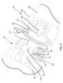
- FIG. 1depicts an exploded cut-away perspective view of an embodiment of a coaxial cable connector with a molded substrate, in accordance with the present invention
- FIG. 2depicts a close-up cut-away perspective view of a first end of an embodiment of a coaxial cable connector with a molded substrate, in accordance with the present invention
- FIG. 3depicts a cut-away perspective view of an embodiment of an assembled coaxial cable connector with a molded substrate, in accordance with the present invention
- FIG. 4depicts a cut-away perspective view of an embodiment of a coaxial cable connector just prior to mating with an embodiment of a male connector, in accordance with the present invention
- FIG. 5depicts a cut-away perspective view of an embodiment of a cable connector during mating with an embodiment of a male connector, in accordance with the present invention
- FIG. 6depicts a cut-away perspective view of an embodiment of a mating force sensing coaxial cable connector mated with an embodiment of a male connector, in accordance with the present invention
- FIG. 7depicts a partial cross-sectional view of a further embodiment of a coaxial cable connector with integrated force mating force sensing circuit, in accordance with the present invention.
- FIGS. 8A and 8Bdepict perspective views of an embodiment of the molded substrate of FIG. 1 , in accordance with the present invention
- FIG. 8Cdepicts a perspective view of an alternative embodiment of a molded substrate 740 , in accordance with the present invention.
- FIG. 8Ddepicts a perspective view of an embodiment of a molded substrate comprising an integrated circuit 504 , in accordance with the present invention.
- FIG. 8Edepicts a top view of an embodiment of a molded substrate, in accordance with the present invention.
- FIG. 8Fdepicts a perspective view of an embodiment of a molded substrate 740 without any components, in accordance with the present invention.
- FIG. 1depicts an exploded cut-away perspective view of an embodiment of a coaxial cable connector 700 , in accordance with the present invention.
- the coaxial cable connector 700may include electrical devices and circuitry including, among other things, a sensing circuit 730 (e.g., an integrated mating force sensing circuit), a coupler 720 , an integrated circuit 504 (illustrated in FIGS. 8C and 8D ), electrical components 562 (e.g., electrical components), conductive interconnects or traces 731 , etc.
- a sensing circuit 730may include, among other things, an integrated mating force sensing circuit, a transducer/sensor (e.g., sensors for generating data regarding a performance, moisture content, temperature, tightness, efficiency, and alarm conditions, etc for the coaxial cable connector 700 ), etc.
- a coupler 720e.g., an antenna
- a coupler 720is configured to: sense a condition or electrical parameter of a signal flowing through a connector at a given time or over a given time period, harvest power from a signal (e.g., an RF signal) flowing through a coaxial connector.
- An electrical parametermay comprise, among other things, an electrical signal (RF) power level, wherein the electrical signal power level may be used for discovering, troubleshooting and eliminating interference issues in a transmission line (e.g., a transmission line used in a cellular telephone system).
- RFelectrical signal
- the coaxial cable connector 700may include internal circuitry that may sense connection conditions, harvest power, store data, and/or determine monitorable variables of physical parameter status such as presence of moisture (humidity detection, as by mechanical, electrical, or chemical means), connection tightness (applied mating force existent between mated components), temperature, pressure, amperage, voltage, signal level, signal frequency, impedance, return path activity, connection location (as to where along a particular signal path a connector 100 is connected), service type, installation date, previous service call date, serial number, etc.
- an insertion of an electrically small low coupling magnetic antennamay be used to harvest power from RF signals and measure an integrity of passing RF signals (i.e., using the electromagnetic fields' fundamental RF behavior).
- the coupler 720may be designed at a very low coupling efficiency in order to avoid insertion loss.
- Harvested powermay be used to power an on board data acquisition structure (e.g., integrated circuit 504 , circuitry 562 , etc).
- Sensed RF signal powermay be fed to an on board data acquisition structure (e.g., integrated circuit 504 ).
- Data gathered by the integrated circuit 504is reported back to a data gathering device (e.g., a transmitter, a receiver, a combiner, etc) through a transmission path (i.e., a coaxial cable) or wirelessly.
- a data gathering devicee.g., a transmitter, a receiver, a combiner, etc
- a transmission pathi.e., a coaxial cable
- the connector 700includes a connector body 750 .
- the connector body 750comprises an outer housing surrounding an internal passageway 755 (shown in FIG. 2 ) accommodating internal components assembled within the connector 700 .
- the connector body 750may be conductive.
- the connector 700comprises a molded substrate 740 being a first insulator component (e.g., as described in detail with respect to FIGS. 8A-8F ).
- a first end 751 of the connector body 750includes a threaded surface 754 .
- the first end 751also includes an axial opening large enough to accommodate the molded substrate 740 and an interface sleeve 760 .
- an opposing second end 752 of the connector body 750includes an axial opening large enough to accommodate a spacer 770 .
- the spacer 770is a second insulator component and is located to operate with an internal surface of the connector body 750 to stabilize a center conductor contact 780 and help retain substantially axial alignment of the center conductor contact 780 with respect to the connector body 750 when the connector 700 is assembled.
- the molded substrate 740is formed of a dielectric material and may be housed within the connector body 750 and positioned to contact and axially align the center conductor 780 .
- the molded substrate 740is positioned to rigidly suspend the inner conductor contact 780 within the outer conducting housing or connector body 750 .
- the molded substrate 740is an insulator component positioned to help facilitate an operable communication connection of the connector 700 .
- the molded substrate 740may include a face 742 (on or within) which a sensing circuit 730 , coupler 720 , conductive interconnects or traces 731 , electrical components 562 , and/or an integrated circuit 504 (e.g., a semiconductor device such as, among other things, a semiconductor chip) that may include any type of data acquisition/transmission/memory circuitry (e.g., an impedance matching circuit, an RF power sensing circuit, a RF power harvesting/power management circuit, etc) may be positioned.
- a sensing circuit 730e.g., coupler 720 , conductive interconnects or traces 731 , electrical components 562 , and/or an integrated circuit 504 (e.g., a semiconductor device such as, among other things, a semiconductor chip) that may include any type of data acquisition/transmission/memory circuitry (e.g., an impedance matching circuit, an RF power sensing circuit, a RF power harvesting/
- the face 742may be the bottom of an annular ring-like channel formed into the molded substrate 740 and the sensing circuit 730 , coupler 720 , conductive interconnects or traces 731 , electrical components 562 , and/or an integrated circuit 504 may be printed onto and/or within the face 742 .
- a capacitive circuitmay be printed on the face 742 of the molded substrate 740 , wherein the capacitive circuit is a sensing circuit 730 .
- Printing the sensing circuit 730 or the aforementioned components onto a face 742 of the molded substrate 740affords efficient connector 700 fabrication because the sensing circuit 730 can be provided on components, such as the molded substrate 740 .
- assembly of the connector 700is made efficient because the various connector components, such as the molded substrate 740 , center conductor 780 , interface sleeve 760 , connector body 750 and spacer 770 are assembled in a manner consistent with typical connector assembly.
- Printing, a sensing circuit 730 , on a typical componentcan also be more efficient than other means because assembly of small non-printed electronic sensors to the interior surfaces of typical connector housings, possibly wiring those sensors to a circuit board within the housing and calibrating the sensors along with any mechanical elements can be difficult and costly steps.
- a printed sensing circuit 730 integrated on a typical connector 700 assembly componentreduces assembly complexity and cost.
- sensing circuits 730 and other associated circuitrymay be desirable to “print” sensing circuits 730 and other associated circuitry in an integrated fashion directly onto structures, such as the face 742 of the molded substrate 740 or other structures already present in a typical connector 700 .
- printing the sensing circuits 730 onto connector 700 componentsallows for mass fabrication, such as batch processing of the first spacers 40 being insulator components having sensing circuits 730 printed thereon.
- Printing the sensing circuit 730may involve providing conductive pathways, or traces, etched from copper sheets or other conductive materials, laminated or otherwise positioned onto a non-conductive substrate, such as the first spacer insulator component 740 .
- An interface sleeve 760 of a connector 700may include a flexible member 762 .
- the flexible member 762is a compliant element of the sleeve 760 . Because the flexible member 762 is compliant, it can bend in response to contact with mechanical elements in the interface of another component, such as a male connector 500 (see FIGS. 4-6 ). Thus, the flexible member 762 may directly experience mating forces when connected to another component, such as a male connector 500 , and undergo movement as a result, as will be discussed further herein below.
- FIG. 2depicts a close-up cut-away perspective view of a first end 751 of an embodiment of a coaxial cable connector 700 with (integrated mating force) sensing circuit 730 , in accordance with the present invention.
- the sensing circuit 730 , coupler 720 , conductive interconnects or traces 731 , electrical components 562 , and/or an integrated circuit 504may be printed on a face 742 of a molded substrate 740 in proximity with a capacitive space 790 , such as a resonant cavity or chamber in the interface between the molded substrate 740 and the interface sleeve 760 .
- the sensing circuit 730may be a capacitive circuit.
- the capacitive space 790 cavitysuch as a cavity or chamber may includes at least one wall or boundary surface movable due to mating forces.
- a surface of the flexible member 762 of the interface sleeve 760may comprise a boundary surface of the capacitive space 790 .
- the flexible member 762is a compliant portion of the interface sleeve 760 operable to endure motion due to movement from mating forces.
- the flexible member 762may be resilient and configured such that motions due to mating forces bend the member 762 within its elastic range so that the member 762 can return to its previous non-motivated position once the mating forces are removed.
- the member 762may also be configured to have some elastic hysteresis in that member 762 may be physically responsive relative to varying motive force and include inherent tendency to return to a previous dynamic physical condition.
- the flexible member 762may be formed such that movement due to motive force is resistive to yielding and/or may also be cable of elastic response only within a specific range of movement. Nevertheless, some embodiments of the flexible member 762 may be designed to yield if moved too far by mating forces.
- the interface sleeve 760may be formed of metals or metal allows such as brass, copper, titanium, or steel, plastics (wherein the plastics may be formed to be conductive), composite materials, or a combination thereof.
- the flexible member 762When the connector 700 is assembled, the flexible member 762 is in immediate proximity with the capacitive space 790 . Movements of the flexible member 762 cause changes in the size associated with the capacitive space 790 .
- the capacitive space 790 sizemay therefore by dynamic. Changes in the size of the capacitive space 790 may produce changes in the capacitance of the printed sensing circuit 730 and are therefore ascertainable as a physical parameter status.
- the face 742 of the insulatormay be or include a fixed electrode, such as a fixed plate 744 , and the flexible member 762 may be or include a movable electrode. The distance between the electrodes, or the size of the capacitive space between the electrodes, may vary inversely with the applied torque.
- the sensing circuit 730translates the changes in capacitance to connector tightness and determines if the connector 700 is too loose.
- the capacitive space 790may be a resonant chamber or capacitive cavity.
- the dimensional space of the capacitive space 790can be easily manufactured to very tight tolerances either by forming at least a portion of the space 790 directly into the molded substrate 740 , forming it into portion of the housing 750 , forming it into a portion of the interface sleeve 760 , or a combination of the above.
- an annular channelmay be formed in molded substrate 740 , wherein a capacitive sensing circuit 730 is positioned on the bottom face 742 of the channel to form an annular diaphragm capacitor responsive to resonant variation due to changes in the size of cavity 790 .
- the capacitive space 790may be filled with air, wherein the air may function as a dielectric.
- the capacitive space 790may be filled with some other material such as dielectric grease.
- portions of the cavity capacitive space 790 boundaries, such as surfaces of the spacer 740 or flexible member 760may be coated with dielectric material.
- the connector 700 assemblycreates a sandwich of parts, the capacitive space or resonant cavity 790 and sensing circuit 730 need not be adjusted or calibrated individually for each connector assembly, making assembly of the connector 700 no different from a similar common coaxial cable connector that has no sensing circuit 730 built in.
- Power for the sensing circuit 730 , electrical components 562 , and/or an integrated circuit 504may be provided through indirect (i.e., via coupler 720 ) or direct (via traces) electrical contact with the center conductor 780 .
- an indirect coupling devicesuch as a directional coupler
- tracesmay be printed on the molded substrate 740 and positioned so that the traces make electrical contact with the center conductor contact 780 at a location 746 .
- a ground pathmay extend through a location 748 between the molded substrate 740 and the interface sleeve 760 .
- a ground isolation circuitmay be provided to generate a negative voltage to be used as a reference signal (i.e., a ground).
- the sensing circuit 730can communicate sensed mating forces.
- the sensing circuit 730such as a capacitive circuit, may be in electrical communication with an output component such as traces or a coupler 720 electrically connected to the center conductor contact 780 .
- sensed conditions due to mating forcessuch as changes in capacitance of the cavity or chamber 790 , may be passed as an output signal from the sensing circuit 730 of the molded substrate 740 through an output component, such as a coupler 720 or traces, electrically linked to the center conductor contact 780 .
- the outputted signal(s)can then travel along the cable line corresponding to the cable connection applicable to the connector 700 .
- the signal(s) from the sensing circuit 730may be accessed at a point along the cable line.
- traces or conductive elements of an output component in communication with a sensing circuit 730may be in electrical contact with output leads available to facilitate connection of the connector 700 with electronic circuitry that can manipulate the sensing circuit 730 operation.
- a portion of the molded substrate 740may be compressible or bendable. As the flexible member 762 of the interface sleeve 760 moves due to mating forces, the flange 747 may compress or bend as it interacts with the flexible member 762 .
- the compressible or bendable nature of a portion of the molded substrate 740may permit more efficient movement of the flexible member 762 .
- the flange 747may contribute resistance to movement of the flexible member 762 , but still allow some bending of the member.
- the molded substrate 740may bend with respect to a rear wall or surface 743 as the flexible member 762 bends due to mating forces and interacts with the molded substrate 740 .
- FIG. 3depicts an embodiment of an assembled coaxial cable connector 700 with integrated mating force sensing circuit 730 .
- the threaded surface 754 of the first end of connector body 750facilitates threadable mating with another coaxial cable component, such as a male connector 500 (see FIGS. 4-6 ).
- the connector 700may be formed without threads and designed to have a tolerance fit with another coaxial cable component, while the sensing circuit 730 is still able to sense mating forces.
- the spacer 770operates with an internal surface of the connector body 750 to stabilize the center conductor contact 780 and help retain substantially axial alignment of the center conductor contact 780 with respect to the connector 700 .
- the molded substrate 740may be seated against an annular ridge 784 located on the center conductor contact 780 . Seating the molded substrate 740 against the annular ridge 784 may help retain the spacer 740 in a substantially fixed position along the axis of connector 700 so that the molded substrate 740 does not axially slip or move due to interaction with the interface sleeve 760 when mating forces are applied.
- the molded substrate 740is located on a spacer portion 782 of the center conductor contact 780 and has a close tolerance fit therewith to help prevent wobbling and/or misalignment of the center conductor contact 780 .
- a connector 700can mate with RF ports of other components or coaxial cable communications devices, such as an RF port 515 of a male connector 500 .
- the RF port 515 of the male connector 500is brought into axial alignment with the mating force sensing connector 700 .
- the two componentsare moved together or apart in a direction 5 , as shown in FIG. 4 .
- the male connector 500may include a connector body 550 including an attached nut 555 having internal threads 554 .
- the male connector 500includes a conductive interface sleeve 560 having a leading edge 562 .
- the interface sleeve 760 of the mating force sensing connector 700may be dimensioned such that during mating the two interface sleeves 760 and 560 slidingly interact.
- the interface sleeve 760may be designed to slidingly interact with the inner surface of the male connector 500 interface sleeve 560 , as shown in FIG. 5 .
- other embodiments of a connector 700may include an interface sleeve 760 designed to slidingly interact with the outside surface of a connector component, such as interface sleeve 560 .
- the sliding interaction of the interface sleeve 760 with the interface sleeve 560may be snug, wherein the tolerance between the parts is close when the mating force sensing connector 700 is being mated to the male connector 500 .
- the female center conductor contact 780 of the force sensing connector 700may include segmented portions 787 .
- the segmented portions 787may facilitate ease of insertion of a male center conductor contact 580 of the male connector 500 .
- the center conductor contact 580 of the male connector 500may include a tapered surface 587 that further eases the insertion of the male center conductor contact 580 into the female center conductor contact 780 .
- a mating force sensing connector 700may include a male center conductor contact 780 configured to mate with a female center conductor contact of another connector component.
- FIG. 5depicts an embodiment of a mating force sensing coaxial cable connector 700 during mating with an embodiment of an RF port 515 of a male connector 500 .
- the interface sleeve 760 of the mating force sensing connector 700may begin to slidingly advance against the inner surface of interface sleeve 560 of the male connector 500 .
- the male center conductor contact 580is axially aligned with the female center conductor contact 780 and readied for insertion therein.
- the leading edge 562 of the interface sleeve 560 of the male connector 500makes contact with the flexible member 762 of the interface sleeve 760 of the mating force sensing connector 700 , as shown in FIG. 6 .
- Contact between the leading edge 562 and the flexible member 762facilitates transfer of force from the interface sleeve 560 to the interface sleeve 760 .
- Mating forcemay be generated by the threading advancement of the nut 555 onto the threaded surface 754 of mating force sensing connector 700 .
- mating forcemay be provided by other means, such as by a user gripping the connector body 550 of the male connector 500 and pushing it in a direction 5 (see FIG. 4 ) into mating condition with the force sensing connector 700 .
- the force placed upon the flexible member 762 by the leading edge 562may cause the flexible member 762 to bend.
- the sensing circuit 730can be calibrated according to the known volume to sense corresponding changes in the volume. For example, if the male connector 500 is not threaded onto the mating force sensing connector 700 enough, then the leading edge 562 of the interface sleeve 560 does not place enough force against the flexible member 762 to bend the flexible member 762 sufficiently enough to create a change in the size of capacitive space 790 that corresponds to a sufficient and appropriate change in capacitance of the space 790 .
- the sensing circuit 730such as a capacitive circuit on the molded substrate 740 , will not sense a change in capacitance sufficient to produce a signal corresponding to a proper mating force attributable to a correct mated condition.
- the leading edge 562 of the interface sleeve 560will place too much force against the flexible member 762 and will bend the flexible member 762 more than is sufficient to create a change in the size of capacitive space 790 that corresponds to a sufficient and appropriate change in capacitance of the space 790 .
- the sensing circuit 730such as a capacitive circuit on the first spacer insulator component 740 , will sense too great a change in capacitance and will produce a signal corresponding to an improper mating force attributable to a too tightly-fitted mated condition.
- Proper mating forcemay be determined when the sensing circuit 730 signals a correct change in electrical capacitance relative to the size of capacitive space 790 .
- the correct change in sizemay correspond to a range of volume or distance, which in turn may correspond to a range of capacitance sensed by the sensing circuit 730 .
- the forcecan be determined to be proper if it causes the flexible member to bend within a range that corresponds to the acceptable range of size change of capacitive space 790 .
- the determination of the range acceptable capacitance changecan be determined through testing and then associated with mating force conditions.
- calibrationmay be attributable to a multitude of mating force sensing connectors 700 having substantially the same configuration.
- the size and material make-up of the various components of the multiple connectors 700can be substantially similar.
- a multitude of mating force connectors 700may be fabricated and assembled to have a regularly defined capacitive space 790 in immediate proximity with a bendable wall or boundary surface, such as flexible member 762 , wherein the capacitive space 790 of each of the multiple connectors 700 is substantially the same size.
- the multiple connectors 700may include a sensing circuit 730 , such as a capacitive circuit, printed on a molded substrate 740 , the molded substrate 740 being an insulator component.
- the sensing circuit 730 on each of the molded substrates 740 of the multiple connectors 700may be substantially similar in electrical layout and function. For instance, the sensing circuit 730 for each of the multiple connectors 700 may sense capacitance substantially similarly. Then, for each of the multitude of connectors 700 , capacitance may predictably change relative to size changes of the capacitive space 790 , attributable to bending of the flexible member 762 corresponding to predictable mating force. Hence, when capacitance falls within a particular range, as sensed by sensing circuit 730 , then mating force can be determined to be proper for each of the multiple connectors 700 having substantially the same design, component make-up, and assembled configuration.
- each connector 700 of the multiple mating force connectors 700 having substantially the same design, component make-up, and assembled configurationdoes not need to be individually calibrated. Calibration can be done for an entire similar product line of connectors 700 . Then periodic testing can assure that the calibration is still accurate for the line. Moreover, because the sensing circuit 730 is integrated into existing connector components, the mating force sensing connector 700 can be assembled in substantially the same way as typical connectors and requires very little, if any, mass assembly modifications.
- FIG. 7depicts a partial cross-sectional view of a further embodiment of a coaxial cable connector 800 with integrated force mating force sensing circuit 830 .
- the mating force sensing circuit 830may be a capacitive circuit positioned on a mount portion 843 of a first face 842 of an embodiment of a molded substrate 840 .
- the capacitive circuit 830may be printed on the mount portion 843 .
- the mount portion 843may protrude somewhat from the first face 842 of the molded substrate 840 to help position the capacitive circuit 830 in immediate proximity with a first section bore 863 of a first section 862 of an interface member 860 to define a capacitive space 890 located between the face 842 and the molded substrate 840 .
- the interface member 860also includes a second section 864 .
- the first section 862 of the interface member 860may be flexible so that it can move between a first non-bent position and a second bent position upon the application of an axial force by a mating component 860 on the first section 862 .
- the first section 862 of the interface member 860may move closer to the first surface 842 of the molded substrate 840 thereby decreasing the volume of the capacitive space 890 existent proximate the capacitive circuit 830 on the mount portion 843 immediately proximate the first section bore 863 of the first section 862 .
- the capacitive circuit 830can detect the decrease in size of the capacitive space 890 and correlate the change in size with mating force exerted on the interface member 860 .
- the connector 800 embodimentmay include a connector body 850 having a threaded portion 854 located proximate a first end of the connector body 850 .
- the first end 751 of the connector 800may axially oppose a second end 852 of the connector 800 (not shown, but similar to second end 752 of connector 700 depicted in FIG. 1 ).
- the connector body 850may include a first bore 856 extending axially from the first end 851 .
- the first bore 856may be large enough to accommodate the first spacing insulator 840 and the interface member 860 so that the connector body 850 may house the molded substrate 840 and the interface member 860 .
- the first end 851including the first bore 851 , may be sized to mate with another coaxial cable component, such as male connector 500 depicted in FIGS. 4-6 .
- FIGS. 1-7An embodiment of a method for detecting an RF signal (or harvesting power) or a mating force of a mated coaxial cable connector 700 , 800 is described with reference to FIGS. 1-7 .
- One step of the mating force detecting methodincludes providing a coaxial cable connector, such as connector 700 or 800 .
- the connector 700 , 800may include a sensing circuit 730 , 830 , coupler 720 , conductive interconnects or traces 731 , electrical components 562 , and/or an integrated circuit 504 positioned on a face 742 , 842 of a spacer component 740 , 840 located within a connector body 750 , 850 .
- the connector 700 , 800may include a capacitive space 790 , 890 in immediate proximity with the sensing circuit 730 , 830 .
- the connector 700 , 800may have an interface component 760 , 860 having a flexible member 762 , 862 forming at least one surface or boundary portion of the capacitive space 790 , 890 .
- the flexible member 762 , 862may be movable due to mating forces.
- Another step of the coaxial cable connector mating force detection methodincludes mating the connector 700 , 800 with a connecting device, such as the male connector 500 , or any other structurally and functionally compatible coaxial cable communications component.
- Yet another mating force detection stepincludes bending the flexible member 762 , 862 of the interface component 760 , 860 due to contact with the connecting device, such as male connector 500 , during mating, thereby reducing the size of the capacitive space 790 , 890 .
- the mating force detection methodologyincludes detecting mating force by sensing the reduction of capacitive space 790 , 890 size by the sensing circuit 730 , 830 . The size change of the space 790 , 890 may then be correlated with the mating force exerted on the interface member 760 , 860 .
- FIGS. 8A and 8Bdepict perspective views of an embodiment of the molded substrate 740 comprising the coupler 720 , integrated circuit 504 , electrical components 562 , and conductive interconnects or traces 731 of FIG. 1 .
- FIGS. 8A and 8Billustrate the coupler 720 mounted to or integrated with the molded substrate 740 .
- Coupler 720 illustrated in FIG. 8Acomprises a loop coupler that includes optional loops 516 a , 516 b , and 516 c for impedance matching, etc.
- the molded substrate 740may comprise a molded interconnect device (e.g., a disk) generated using a laser direct structuring process on syndiotactic polystyrene material with an LDS additive and plated with an electro-less plating process.
- the molded substrate 740is designed to be inserted into a coaxial cable connector housing and provide an electronic sensing and processing platform (i.e., for the sensor 730 , coupler 720 , integrated circuit 504 , electrical components 562 , conductive interconnects or traces 731 ).
- the molded substrate 740may be generated using materials and processes including, among other things, a syndiotactic polystyrene with LDS additive, a liquid crystal polymer with additive, an injection molding process, a laser activation process, an electro-less plating process, etc.
- the molded substrate 740may include multiple sensors defined on its surface to determine a state of a coaxial cable connector and provide information on a status of the connector and quality of an RF signal.
- the molded substrate 740comprises a dielectric material capable of being mechanically inserted into a coaxial cable connector housing without deformation.
- the molded substrate 740acts a platform for mounting sensors used to monitor parameters that measure a viability of RF coaxial cable connectors (e.g., mating tightness, moisture, temperature, impedance, etc.). Additionally, the molded substrate 740 provides a surface for placing micro-antenna structures (e.g., coupler 720 ) used to couple energy from the coaxial cable, measure both the forward and reverse propagating RF voltage signals on a coaxial cable, and provide a coupling connection to the cable for transmitting and receiving data to and from all components on or within the molded substrate 740 .
- micro-antenna structurese.g., coupler 720
- the molded substrate 740may be included in passive transponder system intended to monitor information being sent and received through a transmission line, extract energy from near field RF sources, and sense a state of a remote station over a transmission line such as a coaxial cable.
- the molded substrate 740allows for real time sensing of an RF connector and coaxial cable system reliability.
- FIG. 8Cdepicts a perspective view of an embodiment of a molded substrate 740 a (i.e., an alternative geometry to the geometry of molded substrate 740 ) comprising a top mounted and/or recessed integrated circuit 504 , electrical components 562 , and conductive interconnects or traces 731 .
- the integrated circuit 504 of FIG. 8Cincludes two different versions (either version may be used) of the integrated circuit 504 : a top mounted version 505 a and a recessed mounted version 505 b .
- a combination of the top mounted version 505 a and the recessed mounted version 505 b of the integrated circuit 504may be used in accordance with embodiments of the present invention.
- the molded substrate 740 amay comprise additional electrical components 562 (e.g., transistors, resistors, capacitors, inductors, etc)
- FIG. 8Ddepicts a perspective view of an embodiment of the molded substrate 740 comprising the integrated circuit 504 mounted to or integrated with a side portion of the molded substrate 740 .
- FIG. 8Edepicts a top view of an embodiment of the molded substrate 740 comprising various conductive interconnects or traces 731 (e.g., comprising a metallic material) mounted to or integrated with a top side of the molded substrate 740 .
- various conductive interconnects or traces 731e.g., comprising a metallic material
- FIG. 8Fdepicts a perspective view of an embodiment of the molded substrate 740 without any components.
Landscapes
- Engineering & Computer Science (AREA)
- Microelectronics & Electronic Packaging (AREA)
- Coupling Device And Connection With Printed Circuit (AREA)
Abstract
Description
Claims (22)
Priority Applications (1)
| Application Number | Priority Date | Filing Date | Title |
|---|---|---|---|
| US12/966,113US8419464B2 (en) | 2008-11-17 | 2010-12-13 | Coaxial connector with integrated molded substrate and method of use thereof |
Applications Claiming Priority (2)
| Application Number | Priority Date | Filing Date | Title |
|---|---|---|---|
| US12/271,999US7850482B2 (en) | 2008-11-17 | 2008-11-17 | Coaxial connector with integrated mating force sensor and method of use thereof |
| US12/966,113US8419464B2 (en) | 2008-11-17 | 2010-12-13 | Coaxial connector with integrated molded substrate and method of use thereof |
Related Parent Applications (1)
| Application Number | Title | Priority Date | Filing Date |
|---|---|---|---|
| US12/271,999Continuation-In-PartUS7850482B2 (en) | 2008-11-17 | 2008-11-17 | Coaxial connector with integrated mating force sensor and method of use thereof |
Publications (2)
| Publication Number | Publication Date |
|---|---|
| US20110130034A1 US20110130034A1 (en) | 2011-06-02 |
| US8419464B2true US8419464B2 (en) | 2013-04-16 |
Family
ID=44069237
Family Applications (1)
| Application Number | Title | Priority Date | Filing Date |
|---|---|---|---|
| US12/966,113Expired - Fee RelatedUS8419464B2 (en) | 2008-11-17 | 2010-12-13 | Coaxial connector with integrated molded substrate and method of use thereof |
Country Status (1)
| Country | Link |
|---|---|
| US (1) | US8419464B2 (en) |
Cited By (8)
| Publication number | Priority date | Publication date | Assignee | Title |
|---|---|---|---|---|
| US20110237125A1 (en)* | 2007-09-24 | 2011-09-29 | John Mezzalingua Associates, Inc. | Status sensing and reporting interface |
| US20130183856A1 (en)* | 2012-01-12 | 2013-07-18 | John Mezzalingua Associates, Inc. | Center conductor engagement mechanism |
| US20130288516A1 (en)* | 2012-04-30 | 2013-10-31 | International Business Machines Corporation | An electrical adapter for identifying the connection state to a network |
| US20130303030A1 (en)* | 2012-04-24 | 2013-11-14 | Arteche Lantegi Elkartea, S.A. | High-voltage connector |
| US9368440B1 (en) | 2013-07-31 | 2016-06-14 | Altera Corporation | Embedded coaxial wire and method of manufacture |
| US20160359266A1 (en)* | 2015-06-02 | 2016-12-08 | Pei-Lun Wang | Socket outlet |
| US20180226757A1 (en)* | 2017-01-20 | 2018-08-09 | John Mezzalingua Associates, LLC | Current inhibiting rf connector for coaxial/jumper cables |
| US20210119381A1 (en)* | 2018-04-17 | 2021-04-22 | John Mezzalingua Associates, LLC | Annular abutment/alignment guide for cable connectors |
Families Citing this family (12)
| Publication number | Priority date | Publication date | Assignee | Title |
|---|---|---|---|---|
| US8376774B2 (en) | 2008-11-17 | 2013-02-19 | Rochester Institute Of Technology | Power extracting device and method of use thereof |
| US8414326B2 (en) | 2008-11-17 | 2013-04-09 | Rochester Institute Of Technology | Internal coaxial cable connector integrated circuit and method of use thereof |
| US8303334B2 (en)* | 2008-11-17 | 2012-11-06 | John Mezzalingua Associates, Inc. | Embedded coupler device and method of use thereof |
| US8636522B2 (en)* | 2011-10-28 | 2014-01-28 | Tyco Electronics Corporation | Coaxial connector |
| US8727807B2 (en)* | 2011-10-28 | 2014-05-20 | Tyco Electronics Corporation | Coaxial connector |
| MX340847B (en) | 2012-08-20 | 2016-07-27 | Cooper Technologies Co | LIGHTING APPLICATIONS THAT USE ORGANIC DIODES EMISSING LIGHT. |
| CN103887629A (en)* | 2012-12-22 | 2014-06-25 | 镇江畅远信息科技有限公司 | Radio-frequency coaxial connector |
| US9509146B2 (en)* | 2013-03-05 | 2016-11-29 | Cooper Technologies Company | Inductive power transmission for electrical devices |
| CN106688144A (en)* | 2014-08-12 | 2017-05-17 | 康普技术有限责任公司 | Coaxial cable and connector with capacitive coupling |
| US10811169B2 (en)* | 2016-08-31 | 2020-10-20 | Commscope Technologies Llc | Systems and methods for tamper proof cables |
| DE102020117030A1 (en) | 2020-06-29 | 2021-12-30 | Ims Connector Systems Gmbh | Electrical connector |
| EP4552188A1 (en)* | 2022-07-08 | 2025-05-14 | Samtec, Inc. | Rf connector |
Citations (110)
| Publication number | Priority date | Publication date | Assignee | Title |
|---|---|---|---|---|
| US2640118A (en)* | 1950-12-15 | 1953-05-26 | Edwin G Werner | Coaxial cable connector |
| US3196424A (en) | 1963-09-30 | 1965-07-20 | Thomas K C Hardesty | Cable connector with monitored locking feature |
| US3388590A (en) | 1965-11-29 | 1968-06-18 | Hugh L. Dryden | Connector internal force gauge |
| US3396339A (en) | 1963-11-29 | 1968-08-06 | Varian Associates | Capacitive voltage sensing device including coaxially disposed conductive tubes and electrical discharge inhibition means |
| US3524133A (en) | 1966-09-09 | 1970-08-11 | Gen Electric | Static state voltage and current monitoring device for electric power cable terminations |
| US3657650A (en) | 1969-09-08 | 1972-04-18 | Gen Electric | Current and voltage monitoring module for electric conductor terminations |
| US3686623A (en) | 1968-11-26 | 1972-08-22 | Bunker Ramo | Coaxial cable connector plug |
| US3768089A (en) | 1972-05-18 | 1973-10-23 | Gte Automatic Electric Lab Inc | Jack strip gage |
| US3808580A (en) | 1972-12-18 | 1974-04-30 | Matrix Science Corp | Self-locking coupling nut for electrical connectors |
| US3945704A (en) | 1974-03-28 | 1976-03-23 | Kraus Robert A | Device for detecting an applied compressive load |
| US3960428A (en) | 1975-04-07 | 1976-06-01 | International Telephone And Telegraph Corporation | Electrical connector |
| US3961330A (en) | 1973-12-21 | 1976-06-01 | Ross Alan Davis | Antenna system utilizing currents in conductive body |
| US4034289A (en) | 1976-01-05 | 1977-07-05 | Motorola, Inc. | RF power monitor utilizing bi-directional coupler |
| US4084875A (en) | 1975-01-10 | 1978-04-18 | International Telephone And Telegraph Corporation | Electrical connector |
| US4240445A (en) | 1978-10-23 | 1980-12-23 | University Of Utah | Electromagnetic energy coupler/receiver apparatus and method |
| US4421377A (en) | 1980-09-25 | 1983-12-20 | Georg Spinner | Connector for HF coaxial cable |
| US4489419A (en) | 1981-10-29 | 1984-12-18 | An Wang | Data communication system |
| US4758459A (en)* | 1987-01-28 | 1988-07-19 | Northern Telecom Limited | Molded circuit board |
| US4777381A (en) | 1983-04-13 | 1988-10-11 | Fernandes Roosevelt A | Electrical power line and substation monitoring apparatus and systems |
| US4898759A (en)* | 1988-07-27 | 1990-02-06 | Nidec Corporation | Molded printed circuit board for use with a brushless electric motor |
| US4911655A (en) | 1988-09-19 | 1990-03-27 | Raychem Corporation | Wire connect and disconnect indicator |
| US4915639A (en) | 1988-11-08 | 1990-04-10 | B.A.S.E.C. Industries, Ltd. | "Smart" AC receptacle and complementary plug |
| US4927382A (en) | 1987-11-03 | 1990-05-22 | Siemens Aktiengesellschaft | Electrical function group for a vehicle |
| US5059948A (en) | 1990-07-26 | 1991-10-22 | Tronics 2000, Inc. | Anti-theft security device and alarm |
| US5076797A (en)* | 1990-10-11 | 1991-12-31 | Apple Computer, Inc. | Self-terminating coaxial plug connector for cable end installation |
| US5169329A (en) | 1990-11-28 | 1992-12-08 | Yazaki Corporation | Connector and detector for detecting fitted condition between connector elements |
| EP0527599A1 (en) | 1991-08-12 | 1993-02-17 | Motorola, Inc. | Electrical connector |
| US5194016A (en) | 1990-10-04 | 1993-03-16 | Yazaki Corporation | Connection-condition checkable connectors |
| US5217391A (en) | 1992-06-29 | 1993-06-08 | Amp Incorporated | Matable coaxial connector assembly having impedance compensation |
| US5278525A (en) | 1992-06-11 | 1994-01-11 | John Mezzalingua Assoc. Inc. | Electrical filter with multiple filter sections |
| US5278571A (en) | 1991-10-16 | 1994-01-11 | Tel Instrument Electronics Corp. | RF coupler for measuring RF parameters in the near-field |
| US5345520A (en) | 1993-07-28 | 1994-09-06 | Grile Mark E | Electrical connector with an optical fiber connection detector |
| US5355883A (en) | 1991-12-27 | 1994-10-18 | Gilles Ascher | Electrode connector, in particular for electrocardiogram electrodes, and electrode assembly comprising a connector of this kind |
| US5462450A (en) | 1992-09-07 | 1995-10-31 | Yazaki Corporation | Connector disconnection sensing mechanism |
| US5490033A (en) | 1994-04-28 | 1996-02-06 | Polaroid Corporation | Electrostatic discharge protection device |
| US5491315A (en)* | 1993-09-07 | 1996-02-13 | Raychem Corporation | Switching device with slidable switch |
| US5518420A (en) | 1993-06-01 | 1996-05-21 | Spinner Gmbh Elektrotechnische Fabrik | Electrical connector for a corrugated coaxial cable |
| US5561900A (en) | 1993-05-14 | 1996-10-08 | The Whitaker Corporation | Method of attaching coaxial connector to coaxial cable |
| US5565783A (en) | 1994-09-29 | 1996-10-15 | Pacific Gas And Electric Company | Fault sensor device with radio transceiver |
| US5565784A (en) | 1995-03-20 | 1996-10-15 | Derenne; Lawrence L. | Coaxial cable testing and tracing device |
| US5620330A (en) | 1994-03-15 | 1997-04-15 | Mecaniplast | Connector for coaxial cable |
| US5664962A (en) | 1993-06-14 | 1997-09-09 | Sunx Kabushiki Kaisha | Cable connection for signal processor of separate type sensors |
| US5892430A (en) | 1994-04-25 | 1999-04-06 | Foster-Miller, Inc. | Self-powered powerline sensor |
| US5904578A (en) | 1997-06-05 | 1999-05-18 | Japan Aviation Electronics Industry, Limited | Coaxial receptacle connector having a connection detecting element |
| US5924889A (en) | 1996-12-31 | 1999-07-20 | Wang; Tsan-Chi | Coaxial cable connector with indicator lights |
| US6034521A (en) | 1995-03-23 | 2000-03-07 | Siemens Aktiengesellschaft | Active optical current measuring system |
| US6041644A (en) | 1997-08-25 | 2000-03-28 | Ab Volvo | Device for detection of a defined relative position |
| US6093043A (en) | 1997-04-01 | 2000-07-25 | Itt Manufacturing Enterprises, Inc. | Connector locking mechanism |
| US6134774A (en) | 1995-02-10 | 2000-10-24 | Williams; Deborah | Clamp for clamping coaxial cable connectors to coaxial cables |
| US6193568B1 (en) | 1998-05-22 | 2001-02-27 | Amphenol-Tuchel Electronics Gmbh | Mid connector with extending solder creeping paths |
| US6236551B1 (en) | 1997-10-14 | 2001-05-22 | Polyphaser Corporation | Surge suppressor device |
| US6243654B1 (en) | 1997-10-07 | 2001-06-05 | Telemonitor, Inc. | Transducer assembly with smart connector |
| US6362709B1 (en) | 1999-12-21 | 2002-03-26 | Andrew Corporation | Broadband tap for extracting energy from transmission lines using impedance transformers |
| US6414636B1 (en) | 1999-08-26 | 2002-07-02 | Ball Aerospace & Technologies Corp. | Radio frequency connector for reducing passive inter-modulation effects |
| US20020090958A1 (en) | 1999-03-09 | 2002-07-11 | Ovard David K. | Wireless communication systems, interrogators and methods of communication within a wireless communication system |
| US6490168B1 (en) | 1999-09-27 | 2002-12-03 | Motorola, Inc. | Interconnection of circuit substrates on different planes in electronic module |
| US6549017B2 (en) | 2000-05-04 | 2003-04-15 | Georgia Tech Research Corporation | System and method for on-line impulse frequency response analysis |
| US20030096629A1 (en) | 2001-11-21 | 2003-05-22 | Elliott Brig Barnum | Systems and methods for monitoring RF power |
| US6570373B1 (en) | 2002-03-07 | 2003-05-27 | Visteon Global Technologies, Inc. | Current sensor programmable through connector |
| US20030148660A1 (en) | 2002-02-04 | 2003-08-07 | Devine Edward B. | Watertight device for connecting a transmission line connector to a signal source connector |
| US6618515B2 (en) | 2000-06-21 | 2003-09-09 | Mitsubishi Cable Industries, Ltd. | Connector with a connection detection function, optical fiber cable with a connection detection function, and equipment control mechanism for an optical equipment |
| US6646447B2 (en) | 1999-12-30 | 2003-11-11 | Ambient Corporation | Identifying one of a plurality of wires of a power transmission cable |
| US6650885B2 (en) | 1996-12-06 | 2003-11-18 | Adc Telecommunications, Inc. | RF circuit module |
| US6755681B2 (en) | 2002-05-13 | 2004-06-29 | Delta Electronics, Inc. | Connector with signal detection device |
| US6783389B1 (en) | 2003-08-14 | 2004-08-31 | Hon Hai Precision Ind. Co., Ltd. | Cable connector assembly having detecting contact |
| US20040232919A1 (en) | 2001-06-12 | 2004-11-25 | Glenn Lacey | Fault detection system and method |
| US6859029B2 (en) | 2002-08-06 | 2005-02-22 | Fujitsu Limited | System and method for monitoring high-frequency circuits |
| US6896541B2 (en) | 2003-02-18 | 2005-05-24 | Hewlett-Packard Development Company, L.P. | Interface connector that enables detection of cable connection |
| US6986665B2 (en) | 2002-11-27 | 2006-01-17 | Festo Ag & Co. | Plug connector having a rotatable outgoing cable part |
| US20060019540A1 (en) | 2004-07-26 | 2006-01-26 | Fci Americas Technology, Inc. | Performance indicating electrical connector |
| US7084769B2 (en) | 2002-01-09 | 2006-08-01 | Vue Technology, Inc. | Intelligent station using multiple RF antennae and inventory control system and method incorporating same |
| US7094104B1 (en)* | 2005-05-04 | 2006-08-22 | Andrew Corporation | In-line coaxial circuit assembly |
| US7105982B1 (en) | 2003-03-26 | 2006-09-12 | Polatis Photonics, Inc. | System for optimal energy harvesting and storage from an electromechanical transducer |
| US7173343B2 (en) | 2005-01-28 | 2007-02-06 | Moshe Kugel | EMI energy harvester |
| US7212125B2 (en) | 2001-02-12 | 2007-05-01 | Symbol Technologies, Inc. | Radio frequency identification architecture |
| US20070173367A1 (en) | 2003-10-06 | 2007-07-26 | American Axle & Manufacturing, Inc. | Electronic connector assembly for power transmitting devices |
| US7254511B2 (en) | 2004-01-15 | 2007-08-07 | Bae Systems Information And Electronic Systems Integration Inc. | Method and apparatus for calibrating a frequency domain reflectometer |
| US7253602B2 (en) | 2004-10-12 | 2007-08-07 | Eaton Corporation | Self-powered power bus sensor employing wireless communication |
| US7262626B2 (en) | 2004-04-07 | 2007-08-28 | Agilent Technologies, Inc. | Connection apparatus and cable assembly for semiconductor-device characteristic measurement apparatus |
| US7264493B2 (en)* | 2005-12-07 | 2007-09-04 | Switchcraft, Inc. | High frequency coaxial jack |
| US7266269B2 (en) | 2004-12-16 | 2007-09-04 | General Electric Company | Power harvesting |
| US7268517B2 (en) | 2000-09-27 | 2007-09-11 | Science Applications International Corporation | Method and system for energy reclamation and reuse |
| US7276267B2 (en) | 2002-07-18 | 2007-10-02 | Festo Ag & Co. | Method for the manufacture of an injection molded conductor carrying means |
| US7276703B2 (en) | 2005-11-23 | 2007-10-02 | Lockheed Martin Corporation | System to monitor the health of a structure, sensor nodes, program product, and related methods |
| US7368827B2 (en) | 2006-09-06 | 2008-05-06 | Siemens Power Generation, Inc. | Electrical assembly for monitoring conditions in a combustion turbine operating environment |
| US7413353B2 (en) | 2006-03-29 | 2008-08-19 | Infineon Technologies Ag | Device and method for data transmission between structural units connected by an articulated joint |
| US7440253B2 (en) | 2001-06-15 | 2008-10-21 | Kauffman George M | Protective device |
| US20080258876A1 (en) | 2004-11-05 | 2008-10-23 | Overhultz Gary L | Distributed Antenna Array With Centralized Data Hub For Determining Presence And Location Of RF Tags |
| US7472587B1 (en) | 2007-09-18 | 2009-01-06 | Infineon Technologies Ag | Tire deformation detection |
| US7479886B2 (en) | 2006-08-25 | 2009-01-20 | Intel Corporation | Antenna capacitance for energy storage |
| US20090022067A1 (en) | 2007-07-18 | 2009-01-22 | Acterna Llc | Cable ID Using RFID Devices |
| US7482945B2 (en) | 2006-02-06 | 2009-01-27 | Hall David R | Apparatus for interfacing with a transmission path |
| US7507117B2 (en) | 2007-04-14 | 2009-03-24 | John Mezzalingua Associates, Inc. | Tightening indicator for coaxial cable connector |
| US7513795B1 (en) | 2007-12-17 | 2009-04-07 | Ds Engineering, Llc | Compression type coaxial cable F-connectors |
| US20090096466A1 (en) | 2007-10-10 | 2009-04-16 | Triasx Pty. Ltd. | Passive Intermodulation Test Apparatus |
| US20090115427A1 (en) | 2007-11-07 | 2009-05-07 | Radtke William O | System and Method For Determining The Impedance of a Medium Voltage Power Line |
| US7544086B1 (en) | 2008-03-07 | 2009-06-09 | Evolution Broadband, Llc | Torque indications for coaxial connectors |
| US20090284354A1 (en) | 2008-05-19 | 2009-11-19 | Sirit Technologies Inc. | Multiplexing Radio Frequency Signals |
| US7642611B2 (en) | 2004-04-22 | 2010-01-05 | Panasonic Electric Works Co., Ltd. | Sensor device, sensor system and methods for manufacturing them |
| US20100081324A1 (en) | 2007-09-24 | 2010-04-01 | John Mezzalingua Associates, Inc. | Coaxial cable connector with an internal coupler and method of use thereof |
| US20100124839A1 (en) | 2008-11-17 | 2010-05-20 | John Mezzalingua Associates, Inc. | Coaxial connector with integrated mating force sensor and method of use thereof |
| US20100124838A1 (en) | 2008-11-17 | 2010-05-20 | Noah Montena | Coaxial connector with integrated mating force sensor and method of use thereof |
| US7733236B2 (en) | 2007-09-24 | 2010-06-08 | John Mezzalingua Associates, Inc. | Coaxial cable connector and method of use thereof |
| US7749022B2 (en) | 2007-04-14 | 2010-07-06 | John Mezzalingua Associates, Inc. | Tightening indicator for coaxial cable connector |
| US7775115B2 (en) | 2007-03-14 | 2010-08-17 | Infineon Technologies Ag | Sensor component and method for producing a sensor component |
| US20110077884A1 (en) | 2008-11-17 | 2011-03-31 | Rochester Institute Of Technology | Internal coaxial cable connector integrated circuit and method of use thereof |
| US20110074388A1 (en)* | 2008-11-17 | 2011-03-31 | Rochester Institute Of Technology | Embedded coupler device and method of use thereoff |
| US20110080057A1 (en) | 2008-11-17 | 2011-04-07 | Rochester Institute Of Technology | Power harvesting device and method of use thereof |
| US7930118B2 (en) | 2006-06-13 | 2011-04-19 | Vinden Jonathan Philip | Electricity energy monitor |
| US8092234B2 (en) | 2008-10-30 | 2012-01-10 | Deutsch Engineered Connecting Devices, Inc. | System and method for sensing information that is being communicated through a connector |
- 2010
- 2010-12-13USUS12/966,113patent/US8419464B2/ennot_activeExpired - Fee Related
Patent Citations (115)
| Publication number | Priority date | Publication date | Assignee | Title |
|---|---|---|---|---|
| US2640118A (en)* | 1950-12-15 | 1953-05-26 | Edwin G Werner | Coaxial cable connector |
| US3196424A (en) | 1963-09-30 | 1965-07-20 | Thomas K C Hardesty | Cable connector with monitored locking feature |
| US3396339A (en) | 1963-11-29 | 1968-08-06 | Varian Associates | Capacitive voltage sensing device including coaxially disposed conductive tubes and electrical discharge inhibition means |
| US3388590A (en) | 1965-11-29 | 1968-06-18 | Hugh L. Dryden | Connector internal force gauge |
| US3524133A (en) | 1966-09-09 | 1970-08-11 | Gen Electric | Static state voltage and current monitoring device for electric power cable terminations |
| US3686623A (en) | 1968-11-26 | 1972-08-22 | Bunker Ramo | Coaxial cable connector plug |
| US3657650A (en) | 1969-09-08 | 1972-04-18 | Gen Electric | Current and voltage monitoring module for electric conductor terminations |
| US3768089A (en) | 1972-05-18 | 1973-10-23 | Gte Automatic Electric Lab Inc | Jack strip gage |
| US3808580A (en) | 1972-12-18 | 1974-04-30 | Matrix Science Corp | Self-locking coupling nut for electrical connectors |
| US3961330A (en) | 1973-12-21 | 1976-06-01 | Ross Alan Davis | Antenna system utilizing currents in conductive body |
| US3945704A (en) | 1974-03-28 | 1976-03-23 | Kraus Robert A | Device for detecting an applied compressive load |
| US4084875A (en) | 1975-01-10 | 1978-04-18 | International Telephone And Telegraph Corporation | Electrical connector |
| US3960428A (en) | 1975-04-07 | 1976-06-01 | International Telephone And Telegraph Corporation | Electrical connector |
| US4034289A (en) | 1976-01-05 | 1977-07-05 | Motorola, Inc. | RF power monitor utilizing bi-directional coupler |
| US4240445A (en) | 1978-10-23 | 1980-12-23 | University Of Utah | Electromagnetic energy coupler/receiver apparatus and method |
| US4421377A (en) | 1980-09-25 | 1983-12-20 | Georg Spinner | Connector for HF coaxial cable |
| US4489419A (en) | 1981-10-29 | 1984-12-18 | An Wang | Data communication system |
| US4777381A (en) | 1983-04-13 | 1988-10-11 | Fernandes Roosevelt A | Electrical power line and substation monitoring apparatus and systems |
| US4758459A (en)* | 1987-01-28 | 1988-07-19 | Northern Telecom Limited | Molded circuit board |
| US4927382A (en) | 1987-11-03 | 1990-05-22 | Siemens Aktiengesellschaft | Electrical function group for a vehicle |
| US4898759A (en)* | 1988-07-27 | 1990-02-06 | Nidec Corporation | Molded printed circuit board for use with a brushless electric motor |
| US4911655A (en) | 1988-09-19 | 1990-03-27 | Raychem Corporation | Wire connect and disconnect indicator |
| US4915639A (en) | 1988-11-08 | 1990-04-10 | B.A.S.E.C. Industries, Ltd. | "Smart" AC receptacle and complementary plug |
| US5059948A (en) | 1990-07-26 | 1991-10-22 | Tronics 2000, Inc. | Anti-theft security device and alarm |
| US5194016A (en) | 1990-10-04 | 1993-03-16 | Yazaki Corporation | Connection-condition checkable connectors |
| US5076797A (en)* | 1990-10-11 | 1991-12-31 | Apple Computer, Inc. | Self-terminating coaxial plug connector for cable end installation |
| US5169329A (en) | 1990-11-28 | 1992-12-08 | Yazaki Corporation | Connector and detector for detecting fitted condition between connector elements |
| US5225816A (en) | 1991-08-12 | 1993-07-06 | Motorola, Inc. | Electrical connector with display |
| EP0527599A1 (en) | 1991-08-12 | 1993-02-17 | Motorola, Inc. | Electrical connector |
| US5278571A (en) | 1991-10-16 | 1994-01-11 | Tel Instrument Electronics Corp. | RF coupler for measuring RF parameters in the near-field |
| US5355883A (en) | 1991-12-27 | 1994-10-18 | Gilles Ascher | Electrode connector, in particular for electrocardiogram electrodes, and electrode assembly comprising a connector of this kind |
| US5278525A (en) | 1992-06-11 | 1994-01-11 | John Mezzalingua Assoc. Inc. | Electrical filter with multiple filter sections |
| US5217391A (en) | 1992-06-29 | 1993-06-08 | Amp Incorporated | Matable coaxial connector assembly having impedance compensation |
| US5462450A (en) | 1992-09-07 | 1995-10-31 | Yazaki Corporation | Connector disconnection sensing mechanism |
| US5561900A (en) | 1993-05-14 | 1996-10-08 | The Whitaker Corporation | Method of attaching coaxial connector to coaxial cable |
| US5518420A (en) | 1993-06-01 | 1996-05-21 | Spinner Gmbh Elektrotechnische Fabrik | Electrical connector for a corrugated coaxial cable |
| US5664962A (en) | 1993-06-14 | 1997-09-09 | Sunx Kabushiki Kaisha | Cable connection for signal processor of separate type sensors |
| US5345520A (en) | 1993-07-28 | 1994-09-06 | Grile Mark E | Electrical connector with an optical fiber connection detector |
| US5491315A (en)* | 1993-09-07 | 1996-02-13 | Raychem Corporation | Switching device with slidable switch |
| US5620330A (en) | 1994-03-15 | 1997-04-15 | Mecaniplast | Connector for coaxial cable |
| US5892430A (en) | 1994-04-25 | 1999-04-06 | Foster-Miller, Inc. | Self-powered powerline sensor |
| US5490033A (en) | 1994-04-28 | 1996-02-06 | Polaroid Corporation | Electrostatic discharge protection device |
| US5565783A (en) | 1994-09-29 | 1996-10-15 | Pacific Gas And Electric Company | Fault sensor device with radio transceiver |
| US6134774A (en) | 1995-02-10 | 2000-10-24 | Williams; Deborah | Clamp for clamping coaxial cable connectors to coaxial cables |
| US5565784A (en) | 1995-03-20 | 1996-10-15 | Derenne; Lawrence L. | Coaxial cable testing and tracing device |
| US6034521A (en) | 1995-03-23 | 2000-03-07 | Siemens Aktiengesellschaft | Active optical current measuring system |
| US6650885B2 (en) | 1996-12-06 | 2003-11-18 | Adc Telecommunications, Inc. | RF circuit module |
| US5924889A (en) | 1996-12-31 | 1999-07-20 | Wang; Tsan-Chi | Coaxial cable connector with indicator lights |
| US6093043A (en) | 1997-04-01 | 2000-07-25 | Itt Manufacturing Enterprises, Inc. | Connector locking mechanism |
| US5904578A (en) | 1997-06-05 | 1999-05-18 | Japan Aviation Electronics Industry, Limited | Coaxial receptacle connector having a connection detecting element |
| US6041644A (en) | 1997-08-25 | 2000-03-28 | Ab Volvo | Device for detection of a defined relative position |
| US6243654B1 (en) | 1997-10-07 | 2001-06-05 | Telemonitor, Inc. | Transducer assembly with smart connector |
| US6236551B1 (en) | 1997-10-14 | 2001-05-22 | Polyphaser Corporation | Surge suppressor device |
| US6193568B1 (en) | 1998-05-22 | 2001-02-27 | Amphenol-Tuchel Electronics Gmbh | Mid connector with extending solder creeping paths |
| US20020090958A1 (en) | 1999-03-09 | 2002-07-11 | Ovard David K. | Wireless communication systems, interrogators and methods of communication within a wireless communication system |
| US6414636B1 (en) | 1999-08-26 | 2002-07-02 | Ball Aerospace & Technologies Corp. | Radio frequency connector for reducing passive inter-modulation effects |
| US6490168B1 (en) | 1999-09-27 | 2002-12-03 | Motorola, Inc. | Interconnection of circuit substrates on different planes in electronic module |
| US6362709B1 (en) | 1999-12-21 | 2002-03-26 | Andrew Corporation | Broadband tap for extracting energy from transmission lines using impedance transformers |
| US6646447B2 (en) | 1999-12-30 | 2003-11-11 | Ambient Corporation | Identifying one of a plurality of wires of a power transmission cable |
| US6549017B2 (en) | 2000-05-04 | 2003-04-15 | Georgia Tech Research Corporation | System and method for on-line impulse frequency response analysis |
| US6618515B2 (en) | 2000-06-21 | 2003-09-09 | Mitsubishi Cable Industries, Ltd. | Connector with a connection detection function, optical fiber cable with a connection detection function, and equipment control mechanism for an optical equipment |
| US7268517B2 (en) | 2000-09-27 | 2007-09-11 | Science Applications International Corporation | Method and system for energy reclamation and reuse |
| US7212125B2 (en) | 2001-02-12 | 2007-05-01 | Symbol Technologies, Inc. | Radio frequency identification architecture |
| US20040232919A1 (en) | 2001-06-12 | 2004-11-25 | Glenn Lacey | Fault detection system and method |
| US7440253B2 (en) | 2001-06-15 | 2008-10-21 | Kauffman George M | Protective device |
| US20030096629A1 (en) | 2001-11-21 | 2003-05-22 | Elliott Brig Barnum | Systems and methods for monitoring RF power |
| US7084769B2 (en) | 2002-01-09 | 2006-08-01 | Vue Technology, Inc. | Intelligent station using multiple RF antennae and inventory control system and method incorporating same |
| US20030148660A1 (en) | 2002-02-04 | 2003-08-07 | Devine Edward B. | Watertight device for connecting a transmission line connector to a signal source connector |
| US7029327B2 (en) | 2002-02-04 | 2006-04-18 | Andrew Corporation | Watertight device for connecting a transmission line connector to a signal source connector |
| US6570373B1 (en) | 2002-03-07 | 2003-05-27 | Visteon Global Technologies, Inc. | Current sensor programmable through connector |
| US6755681B2 (en) | 2002-05-13 | 2004-06-29 | Delta Electronics, Inc. | Connector with signal detection device |
| US7276267B2 (en) | 2002-07-18 | 2007-10-02 | Festo Ag & Co. | Method for the manufacture of an injection molded conductor carrying means |
| US6859029B2 (en) | 2002-08-06 | 2005-02-22 | Fujitsu Limited | System and method for monitoring high-frequency circuits |
| US6986665B2 (en) | 2002-11-27 | 2006-01-17 | Festo Ag & Co. | Plug connector having a rotatable outgoing cable part |
| US6896541B2 (en) | 2003-02-18 | 2005-05-24 | Hewlett-Packard Development Company, L.P. | Interface connector that enables detection of cable connection |
| US7105982B1 (en) | 2003-03-26 | 2006-09-12 | Polatis Photonics, Inc. | System for optimal energy harvesting and storage from an electromechanical transducer |
| US6783389B1 (en) | 2003-08-14 | 2004-08-31 | Hon Hai Precision Ind. Co., Ltd. | Cable connector assembly having detecting contact |
| US20070173367A1 (en) | 2003-10-06 | 2007-07-26 | American Axle & Manufacturing, Inc. | Electronic connector assembly for power transmitting devices |
| US7254511B2 (en) | 2004-01-15 | 2007-08-07 | Bae Systems Information And Electronic Systems Integration Inc. | Method and apparatus for calibrating a frequency domain reflectometer |
| US7262626B2 (en) | 2004-04-07 | 2007-08-28 | Agilent Technologies, Inc. | Connection apparatus and cable assembly for semiconductor-device characteristic measurement apparatus |
| US7642611B2 (en) | 2004-04-22 | 2010-01-05 | Panasonic Electric Works Co., Ltd. | Sensor device, sensor system and methods for manufacturing them |
| US20060019540A1 (en) | 2004-07-26 | 2006-01-26 | Fci Americas Technology, Inc. | Performance indicating electrical connector |
| US7253602B2 (en) | 2004-10-12 | 2007-08-07 | Eaton Corporation | Self-powered power bus sensor employing wireless communication |
| US20080258876A1 (en) | 2004-11-05 | 2008-10-23 | Overhultz Gary L | Distributed Antenna Array With Centralized Data Hub For Determining Presence And Location Of RF Tags |
| US7266269B2 (en) | 2004-12-16 | 2007-09-04 | General Electric Company | Power harvesting |
| US7173343B2 (en) | 2005-01-28 | 2007-02-06 | Moshe Kugel | EMI energy harvester |
| US7094104B1 (en)* | 2005-05-04 | 2006-08-22 | Andrew Corporation | In-line coaxial circuit assembly |
| US7276703B2 (en) | 2005-11-23 | 2007-10-02 | Lockheed Martin Corporation | System to monitor the health of a structure, sensor nodes, program product, and related methods |
| US7264493B2 (en)* | 2005-12-07 | 2007-09-04 | Switchcraft, Inc. | High frequency coaxial jack |
| US7482945B2 (en) | 2006-02-06 | 2009-01-27 | Hall David R | Apparatus for interfacing with a transmission path |
| US7413353B2 (en) | 2006-03-29 | 2008-08-19 | Infineon Technologies Ag | Device and method for data transmission between structural units connected by an articulated joint |
| US7930118B2 (en) | 2006-06-13 | 2011-04-19 | Vinden Jonathan Philip | Electricity energy monitor |
| US7479886B2 (en) | 2006-08-25 | 2009-01-20 | Intel Corporation | Antenna capacitance for energy storage |
| US7368827B2 (en) | 2006-09-06 | 2008-05-06 | Siemens Power Generation, Inc. | Electrical assembly for monitoring conditions in a combustion turbine operating environment |
| US7775115B2 (en) | 2007-03-14 | 2010-08-17 | Infineon Technologies Ag | Sensor component and method for producing a sensor component |
| US7749022B2 (en) | 2007-04-14 | 2010-07-06 | John Mezzalingua Associates, Inc. | Tightening indicator for coaxial cable connector |
| US7507117B2 (en) | 2007-04-14 | 2009-03-24 | John Mezzalingua Associates, Inc. | Tightening indicator for coaxial cable connector |
| US20090022067A1 (en) | 2007-07-18 | 2009-01-22 | Acterna Llc | Cable ID Using RFID Devices |
| US7472587B1 (en) | 2007-09-18 | 2009-01-06 | Infineon Technologies Ag | Tire deformation detection |
| US7733236B2 (en) | 2007-09-24 | 2010-06-08 | John Mezzalingua Associates, Inc. | Coaxial cable connector and method of use thereof |
| US8149127B2 (en) | 2007-09-24 | 2012-04-03 | John Mezzalingua Associates, Inc. | Coaxial cable connector with an internal coupler and method of use thereof |
| US20100081324A1 (en) | 2007-09-24 | 2010-04-01 | John Mezzalingua Associates, Inc. | Coaxial cable connector with an internal coupler and method of use thereof |
| US20090096466A1 (en) | 2007-10-10 | 2009-04-16 | Triasx Pty. Ltd. | Passive Intermodulation Test Apparatus |
| US20090115427A1 (en) | 2007-11-07 | 2009-05-07 | Radtke William O | System and Method For Determining The Impedance of a Medium Voltage Power Line |
| US7513795B1 (en) | 2007-12-17 | 2009-04-07 | Ds Engineering, Llc | Compression type coaxial cable F-connectors |
| US7544086B1 (en) | 2008-03-07 | 2009-06-09 | Evolution Broadband, Llc | Torque indications for coaxial connectors |
| US20090284354A1 (en) | 2008-05-19 | 2009-11-19 | Sirit Technologies Inc. | Multiplexing Radio Frequency Signals |
| US8092234B2 (en) | 2008-10-30 | 2012-01-10 | Deutsch Engineered Connecting Devices, Inc. | System and method for sensing information that is being communicated through a connector |
| US20100124839A1 (en) | 2008-11-17 | 2010-05-20 | John Mezzalingua Associates, Inc. | Coaxial connector with integrated mating force sensor and method of use thereof |
| US20100124838A1 (en) | 2008-11-17 | 2010-05-20 | Noah Montena | Coaxial connector with integrated mating force sensor and method of use thereof |
| US7850482B2 (en) | 2008-11-17 | 2010-12-14 | John Mezzalingua Associates, Inc. | Coaxial connector with integrated mating force sensor and method of use thereof |
| US7909637B2 (en) | 2008-11-17 | 2011-03-22 | John Mezzalingua Associates, Inc. | Coaxial connector with integrated mating force sensor and method of use thereof |
| US20110077884A1 (en) | 2008-11-17 | 2011-03-31 | Rochester Institute Of Technology | Internal coaxial cable connector integrated circuit and method of use thereof |
| US20110074388A1 (en)* | 2008-11-17 | 2011-03-31 | Rochester Institute Of Technology | Embedded coupler device and method of use thereoff |
| US20110080057A1 (en) | 2008-11-17 | 2011-04-07 | Rochester Institute Of Technology | Power harvesting device and method of use thereof |
Non-Patent Citations (8)
| Title |
|---|
| International Search Report and Written Opinion. PCT/US2010/052861. Date of Mailing: Jun. 24, 2011. 9 pages. |
| Notice of Allowance (Mail date Jul. 11, 2012) for U.S. Appl. No. 12/960,592, filed Dec. 6, 2010. |
| Office Action (Mail date Jul. 12, 2012) for U.S. Appl. No. 12/961,555, filed Dec. 7, 2010. |
| Office Action (Mail date Jun. 28, 2012) for U.S. Appl. No. 12/965,961, filed Dec. 13, 2010. |
| U.S. Appl. No. 12/271,999, filed Nov. 17, 2008. Customer No. 5417. |
| U.S. Appl. No. 12/960,592, filed Dec. 6, 2010; Confirmation No. 7529. |
| U.S. Appl. No. 12/961,555, filed Dec. 7, 2010; Confirmation No. 9390. |
| U.S. Appl. No. 12/965,961, filed Dec. 13, 2010; Confirmation No. 7882. |
Cited By (15)
| Publication number | Priority date | Publication date | Assignee | Title |
|---|---|---|---|---|
| US8773255B2 (en) | 2007-09-24 | 2014-07-08 | Ppc Broadband, Inc. | Status sensing and reporting interface |
| US20110237125A1 (en)* | 2007-09-24 | 2011-09-29 | John Mezzalingua Associates, Inc. | Status sensing and reporting interface |
| US20130183856A1 (en)* | 2012-01-12 | 2013-07-18 | John Mezzalingua Associates, Inc. | Center conductor engagement mechanism |
| US9099825B2 (en)* | 2012-01-12 | 2015-08-04 | John Mezzalingua Associates, LLC | Center conductor engagement mechanism |
| US20130303030A1 (en)* | 2012-04-24 | 2013-11-14 | Arteche Lantegi Elkartea, S.A. | High-voltage connector |
| US9209575B2 (en)* | 2012-04-24 | 2015-12-08 | Arteche Lantegi Elkartea, S.A. | High-voltage connector |
| US9093774B2 (en)* | 2012-04-30 | 2015-07-28 | International Business Machines Corporation | Electrical adapter for identifying the connection state to a network |
| US20130288516A1 (en)* | 2012-04-30 | 2013-10-31 | International Business Machines Corporation | An electrical adapter for identifying the connection state to a network |
| US9368440B1 (en) | 2013-07-31 | 2016-06-14 | Altera Corporation | Embedded coaxial wire and method of manufacture |
| US20160359266A1 (en)* | 2015-06-02 | 2016-12-08 | Pei-Lun Wang | Socket outlet |
| US9905967B2 (en)* | 2015-06-02 | 2018-02-27 | Pei-Lun Wang | Socket outlet with expansion module |
| US20180226757A1 (en)* | 2017-01-20 | 2018-08-09 | John Mezzalingua Associates, LLC | Current inhibiting rf connector for coaxial/jumper cables |
| US10297960B2 (en)* | 2017-01-20 | 2019-05-21 | John Mezzalingua Associates, LLC | Current inhibiting RF connector for coaxial/jumper cables |
| US20210119381A1 (en)* | 2018-04-17 | 2021-04-22 | John Mezzalingua Associates, LLC | Annular abutment/alignment guide for cable connectors |
| US11695237B2 (en)* | 2018-04-17 | 2023-07-04 | John Mezzalingua Associates, LLC | Annular abutment/alignment guide for cable connectors |
Also Published As
| Publication number | Publication date |
|---|---|
| US20110130034A1 (en) | 2011-06-02 |
Similar Documents
| Publication | Publication Date | Title |
|---|---|---|
| US8419464B2 (en) | Coaxial connector with integrated molded substrate and method of use thereof | |
| US7850482B2 (en) | Coaxial connector with integrated mating force sensor and method of use thereof | |
| US7909637B2 (en) | Coaxial connector with integrated mating force sensor and method of use thereof | |
| US8303334B2 (en) | Embedded coupler device and method of use thereof | |
| US7768461B2 (en) | Antenna device with insert-molded antenna pattern | |
| US10069257B1 (en) | Inline compression RF connector | |
| US20100222105A1 (en) | Wireless data communication card with compact antenna | |
| US20170033511A1 (en) | Electrical connector having good anti-emi perfprmance | |
| US8376774B2 (en) | Power extracting device and method of use thereof | |
| US20100248503A1 (en) | Connector capable of coupling to printed circuit board | |
| JP2002313498A (en) | High speed and high density mutual connection system for use of differential and single end transmission | |
| WO2010008516A1 (en) | Low-profile mounted push-on connector | |
| CN107078445A (en) | Plug-in connectors for capacitive data transfer | |
| US12100905B2 (en) | Multiple coaxial cable connector | |
| JP2009104836A (en) | Connector plug | |
| CN111048959A (en) | Connect the switch | |
| US20070216582A1 (en) | Antenna device with ion-implanted antenna pattern | |
| US7786821B2 (en) | Compact end launch transition including a body with an antenna and an electrical connector | |
| US7724106B2 (en) | Coaxial connecting part | |
| KR20180054230A (en) | Coaxial connector plug and RF connector including the same | |
| JP2010097823A (en) | Coaxial connector assembly | |
| JP2007232678A (en) | Apparatus and method for measuring relative permittivity of dielectric material in printed board | |
| EP3635818B1 (en) | Cable connector to pcb interconnect | |
| KR20120011617A (en) | Coupler for Wireless Communication Equipment | |
| JP6610309B2 (en) | Coaxial connector device |
Legal Events
| Date | Code | Title | Description |
|---|---|---|---|
| AS | Assignment | Owner name:JOHN MEZZALINGUA ASSOCIATES, INC., NEW YORK Free format text:ASSIGNMENT OF ASSIGNORS INTEREST;ASSIGNORS:MONTENA, NOAH;BOWMAN, ROBERT;VAUGHAN, RYAN;SIGNING DATES FROM 20101130 TO 20110128;REEL/FRAME:025801/0321 Owner name:ROCHESTER INSTITUTE OF TECHNOLOGY, NEW YORK Free format text:ASSIGNMENT OF ASSIGNORS INTEREST;ASSIGNORS:MONTENA, NOAH;BOWMAN, ROBERT;VAUGHAN, RYAN;SIGNING DATES FROM 20101130 TO 20110128;REEL/FRAME:025801/0321 | |
| AS | Assignment | Owner name:MR ADVISERS LIMITED, NEW YORK Free format text:CHANGE OF NAME;ASSIGNOR:JOHN MEZZALINGUA ASSOCIATES, INC.;REEL/FRAME:029800/0479 Effective date:20120911 | |
| AS | Assignment | Owner name:PPC BROADBAND, INC., NEW YORK Free format text:CHANGE OF NAME;ASSIGNOR:MR ADVISERS LIMITED;REEL/FRAME:029803/0437 Effective date:20121105 | |
| STCF | Information on status: patent grant | Free format text:PATENTED CASE | |
| FPAY | Fee payment | Year of fee payment:4 | |
| FEPP | Fee payment procedure | Free format text:MAINTENANCE FEE REMINDER MAILED (ORIGINAL EVENT CODE: REM.); ENTITY STATUS OF PATENT OWNER: LARGE ENTITY | |
| LAPS | Lapse for failure to pay maintenance fees | Free format text:PATENT EXPIRED FOR FAILURE TO PAY MAINTENANCE FEES (ORIGINAL EVENT CODE: EXP.); ENTITY STATUS OF PATENT OWNER: LARGE ENTITY | |
| STCH | Information on status: patent discontinuation | Free format text:PATENT EXPIRED DUE TO NONPAYMENT OF MAINTENANCE FEES UNDER 37 CFR 1.362 | |
| FP | Lapsed due to failure to pay maintenance fee | Effective date:20210416 |