US8419429B2 - Implant prosthetic part set and method of manufacturing replication plaster model including abutment using the same - Google Patents
Implant prosthetic part set and method of manufacturing replication plaster model including abutment using the sameDownload PDFInfo
- Publication number
- US8419429B2 US8419429B2US13/254,215US201013254215AUS8419429B2US 8419429 B2US8419429 B2US 8419429B2US 201013254215 AUS201013254215 AUS 201013254215AUS 8419429 B2US8419429 B2US 8419429B2
- Authority
- US
- United States
- Prior art keywords
- impression
- abutment
- attachment part
- fixture
- end portion
- Prior art date
- Legal status (The legal status is an assumption and is not a legal conclusion. Google has not performed a legal analysis and makes no representation as to the accuracy of the status listed.)
- Active - Reinstated
Links
- 239000007943implantSubstances0.000titleclaimsabstractdescription30
- 239000011505plasterSubstances0.000titleclaimsabstractdescription28
- 238000004519manufacturing processMethods0.000titleclaimsabstractdescription15
- 230000010076replicationEffects0.000titleclaimsabstractdescription9
- 210000000988bone and boneAnatomy0.000claimsabstractdescription18
- 210000000214mouthAnatomy0.000claimsabstractdescription16
- 239000000463materialSubstances0.000claimsdescription29
- 210000001519tissueAnatomy0.000claimsdescription6
- 238000000034methodMethods0.000claimsdescription5
- 239000004053dental implantSubstances0.000description5
- 238000001356surgical procedureMethods0.000description4
- 208000035143Bacterial infectionDiseases0.000description2
- 230000000844anti-bacterial effectEffects0.000description2
- 208000022362bacterial infectious diseaseDiseases0.000description2
- 230000008878couplingEffects0.000description2
- 238000010168coupling processMethods0.000description2
- 238000005859coupling reactionMethods0.000description2
- 210000003128headAnatomy0.000description2
- 238000010883osseointegrationMethods0.000description2
- 238000011084recoveryMethods0.000description2
- 229910001316Ag alloyInorganic materials0.000description1
- 208000006389Peri-ImplantitisDiseases0.000description1
- BQCADISMDOOEFD-UHFFFAOYSA-NSilverChemical compound[Ag]BQCADISMDOOEFD-UHFFFAOYSA-N0.000description1
- RTAQQCXQSZGOHL-UHFFFAOYSA-NTitaniumChemical compound[Ti]RTAQQCXQSZGOHL-UHFFFAOYSA-N0.000description1
- 238000005299abrasionMethods0.000description1
- 208000002925dental cariesDiseases0.000description1
- 230000000694effectsEffects0.000description1
- 238000002513implantationMethods0.000description1
- 238000003754machiningMethods0.000description1
- 238000012986modificationMethods0.000description1
- 230000004048modificationEffects0.000description1
- 230000002093peripheral effectEffects0.000description1
- 230000003252repetitive effectEffects0.000description1
- 229910052709silverInorganic materials0.000description1
- 239000004332silverSubstances0.000description1
- 210000004872soft tissueAnatomy0.000description1
- 238000004659sterilization and disinfectionMethods0.000description1
- 229910052719titaniumInorganic materials0.000description1
- 239000010936titaniumSubstances0.000description1
- 210000004746tooth rootAnatomy0.000description1
Images


Classifications
- A—HUMAN NECESSITIES
- A61—MEDICAL OR VETERINARY SCIENCE; HYGIENE
- A61C—DENTISTRY; APPARATUS OR METHODS FOR ORAL OR DENTAL HYGIENE
- A61C8/00—Means to be fixed to the jaw-bone for consolidating natural teeth or for fixing dental prostheses thereon; Dental implants; Implanting tools
- A—HUMAN NECESSITIES
- A61—MEDICAL OR VETERINARY SCIENCE; HYGIENE
- A61C—DENTISTRY; APPARATUS OR METHODS FOR ORAL OR DENTAL HYGIENE
- A61C8/00—Means to be fixed to the jaw-bone for consolidating natural teeth or for fixing dental prostheses thereon; Dental implants; Implanting tools
- A61C8/0001—Impression means for implants, e.g. impression coping
- A—HUMAN NECESSITIES
- A61—MEDICAL OR VETERINARY SCIENCE; HYGIENE
- A61C—DENTISTRY; APPARATUS OR METHODS FOR ORAL OR DENTAL HYGIENE
- A61C13/00—Dental prostheses; Making same
- A61C13/34—Making or working of models, e.g. preliminary castings, trial dentures; Dowel pins [4]
- A—HUMAN NECESSITIES
- A61—MEDICAL OR VETERINARY SCIENCE; HYGIENE
- A61C—DENTISTRY; APPARATUS OR METHODS FOR ORAL OR DENTAL HYGIENE
- A61C8/00—Means to be fixed to the jaw-bone for consolidating natural teeth or for fixing dental prostheses thereon; Dental implants; Implanting tools
- A61C8/0048—Connecting the upper structure to the implant, e.g. bridging bars
- A61C8/005—Connecting devices for joining an upper structure with an implant member, e.g. spacers
- A61C8/0068—Connecting devices for joining an upper structure with an implant member, e.g. spacers with an additional screw
Definitions
- the present inventionrelates to an implant prosthetic part set and a method of manufacturing replication plaster model including an abutment using the same, which can take an impression of the location and the shape of a fixture in an oral cavity without using a typical impression copping, in order to manufacture an upper prosthesis coupled to the fixture implanted into an alveolar bone.
- implantsmean implanting an artificial tooth into a dental bone.
- a dental root formed of titaniumis implanted into an alveolar bone, and then an artificial tooth is fixed thereon to recover the function of the original tooth.
- the implantscan be used semi-permanently.
- implantsmay facilitate the recovery of a single missing tooth and improve the function of an artificial tooth for a partially or completely edentulous patient, and may improve dental prosthesis recovery in terms of aesthetic. Furthermore, implants disperse an excessive stress applied on tissues of a support bone therearound.
- a fixtureis implanted into an alveolar bone, and after a certain period (about three to six months) for osseointegration, an impression copping is screwed into a hole of an upper portion of the fixture. Thereafter, an impression copping fixing screw (guide screw) is inserted into an upper portion of the impression copping to secure the impression copping and the fixture, and then surrounding teeth and the above-described parts are coated with an impression material. The impression copping fixing screw projecting from the impression material is then unscrewed to obtain an impression in which the impression copping separated from the fixture is fixed.
- guide screwguide screw
- the impression copping in the impressionis coupled with a virtual fixture (analog), and is fixed with the impression copping fixing screw.
- plasteris filled in the impression to be hardened, and then the impression copping fixing screw is unscrewed to remove the impression and the impression copping, remaining a plaster model.
- an abutmentis coupled to the plaster model, and a crown (artificial tooth) is formed on the abutment.
- the analogis twice coupled to the impression copping and the abutment, resulting in poor bonding due to abrasion of the analog.
- the prosthetic surgeryis not economical because the disposable impression copping used in the surgery should be discarded.
- Korean Patent Publication No. 10-2009-0014027discloses a dental implant material including a silver or silver alloy layer with a nanometer or micrometer thickness formed on at least a portion of the surface of the dental implant material.
- an abutment screw of the dental implant materialis improved in a unscrew protection function, and can show an anti-bacterial effect that can prevent bacterial infection.
- an abutment of the dental implant materialcan show an anti-bacterial effect that can prevent bacterial infection, and can prevent peri-implantitis.
- Korean Patent Registration No. 10-0671710discloses an implant driver with a free angle, including a power combination unit for mounting a handle or a handpiece to a power shaft delivering a rotation force; a rotation force delivering unit delivering the rotation force to a work shaft of a driver; a driver performing a work on the work shaft; and a path guiding unit for guiding from the power shaft to the work shaft.
- Korean Patent Registration No. 10-0842096discloses a block body becoming an abutment, an upper artificial tooth structure, or a complex body of the abutment and the upper artificial tooth structure through machining, and including a connection part that prevents rotation upon combination with a fixture or a dental prosthesis on one side thereof, in which a connection structure is formed in a dental implant abutment and an upper structure.
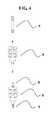
- an impression copping ( 4 ) of FIG. 4has been used, and in order to manufacture an implant crown, the following processes have been performed to manufacture a plaster model in which an abutment is combined at the same place as the oral cavity of a patient.
- An impression copping ( 4 )is inserted in an upper portion of a fixture (not shown).
- a guide screw ( 5 )is then downwardly screwed into the fixture through a central hole of the impression copping ( 4 ).
- An impression materialis filled in an impression tray having holes allowing the guide screw to be exposed.
- the impression copping, surrounding teeth, and oral soft tissuesare covered with the impression tray to be coated with impression material.
- the impression tray including the impression copping in accordance with the shape of the surrounding teeth and the fixtureis removed from the oral cavity of a patient to be sent to a prosthetic dental laboratory.
- An analog(a dental duplication fixture) is aligned with the impression copping fixed in the impression material of the impression tray.
- the guide screwis screwed through the central hole of the impression copping to fix the analog to the lower portion of the impression copping.
- Plasteris filled in a negative mold formed of the impression material and is then hardened.
- An abutment ( 3 )is inserted into the plaster model in which the analog is uprightly implanted in accordance with the condition of the oral cavity of a patient, and the abutment is fixed to the plaster model by an abutment fixing screw ( 1 ) to complete the plaster model.
- the process in the dental laboratoryis complex or error-prone. Also, there is an economic limitation in that the impression copping has to be disposably used.
- the present inventionprovides an implant prosthetic part set and a method of manufacturing replication plaster model including an abutment using the same, which prevents an error generated from deformation of the combination shape (hex screw) of an impression copping with a fixture when the impression copping is reused through sterilization and disinfection.
- an implant prosthetic part setincludes: an abutment adapted to be inserted into an upper portion of a fixture adapted to be implanted into an alveolar bone; an impression attachment part screwed into an upper portion of the abutment; and an abutment fixing screw for fixing a combination body of the abutment and the impression attachment part to the fixture, wherein: the abutment has a cylindrical shape and a through hole vertically passing therethrough and has a female screw thread on an inner circumferential surface of an upper end portion thereof; a diameter of the abutment becomes narrower as getting closer to a lower end portion thereof; and the lower end portion thereof has a hexagonal shape.
- the present inventiondoes not use an impression copping, it is economic. Also, since a plaster model is manufactured in a state where an abutment is mounted, the plaster model can be more exactly manufactured, and the dental laboratory work is simpler. In addition, since an appropriate abutment can be selected in the oral cavity of a patient, it is possible to manufacture an upper prosthesis that further matches an actual oral cavity, and solve a reduction of accuracy generated from repetitive use of the impression copping.
- FIG. 1is a view illustrating an implant prosthesis set according to an embodiment of the present invention.
- FIG. 2is an exploded view illustrating an exemplary implant prosthesis set according to an embodiment of the present invention.
- FIG. 3is a view illustrating another exemplary implant prosthesis set according to an embodiment of the present invention.
- FIG. 4is a view illustrating a conventional implant prosthesis set.
- a fixtureis implanted into an alveolar bone of a patient. After a certain period (about 3 months to about 6 months) for osseointegration of the fixture, a replication plaster model for dental laboratory may be manufactured to have the same shape as the surrounding shape of the position where the fixture is implanted in the oral cavity to manufacture an upper prosthesis (artificial tooth).
- a complex body of an impression material combination part and an abutment fit for the fixture and matching the oral environmentmay be inserted into the fixture.
- a hex driver(such as a head hole of an abutment fixing screw) may be loaded in the central hole of the complex body, and then the abutment fixing screw may be fastened to fix the complex body and the fixture (here, the hex driver is left intact).
- Impression materialmay be loaded in an impression tray having a hole that can expose the impression material using the hex driver.
- the impression traymay cover the complex body and parts including surrounding teeth and oral tissues, and impression material may be coated thereon.
- the abutment fixing screw fastened on the fixturemay be unscrewed using the hex driver.
- the tray including the impression material with the complex bodymay be carefully removed from the oral cavity (here, the inside of the tray may have a negative mold according to the lower portion of the abutment coupled to the fixture, surrounding teeth, and surrounding tissues).
- an analog(replication fixture for dental laboratory work, having the same shape as the fixture, hereinafter, referred to as analog) may be fitted to the lower portion of the complex body of abutment and impression attachment part buried in the impression material.
- the analog and the lower portion of the abutmentmay be fixed by an abutment fixing screw, and then plaster may be poured into the inner surface of the impression tray and be hardened. Thereafter, the impression material may be removed, and then the impression attachment part may be turned to be removed from the abutment.
- a plaster model in which the abutment is connected in the oral cavitymay be manufactured.
- An artificial crownmay be formed on the abutment of the plaster model.
- the abutment and the artificial crownmay be removed from the plaster model for dental laboratory work, and may be fixed on the fixture in the oral cavity of a patient.
- the plaster model for dental laboratory work, in which the analog is implanted,may be discarded.
- the present inventionrelates to an implant prosthetic part set and a method of manufacturing replication plaster model including an abutment using the same, which can take an impression of the location and the shape of a fixture in an oral cavity without using a typical impression copping, in order to manufacture an upper prosthesis coupled to the fixture implanted into an alveolar bone.
- FIG. 1is a view illustrating an implant prosthesis set according to an embodiment of the present invention.
- FIG. 2is an exploded view illustrating an exemplary implant prosthesis set according to an embodiment of the present invention.
- FIG. 3is a view illustrating another exemplary implant prosthesis set according to an embodiment of the present invention.
- FIG. 4is a view illustrating a conventional implant prosthesis set. There are shown an abutment fixing screw 1 , an impression attachment part 2 and 2 - 1 , an abutment 3 and 3 - 1 , an impression copping fixing screw (guide screw) 5 , and an impression copping 4 .
- the implant prosthetic part setmay include an abutment 3 and 3 - 1 inserted into an upper portion of a fixture implanted into an alveolar bone, an impression attachment screwed into an upper portion of the abutment 3 and 3 - 1 , and an abutment fixing screw 1 for fixing a combination body of the abutment 3 and 3 - 1 and the impression attachment part 2 and 2 - 1 to the fixture.
- the abutment 3may be formed to have a cylindrical shape and a through hole vertically passing therethrough.
- the abutment 3may have a female screw thread on the inner circumferential surface of the upper end thereof.
- the diameter of the abutment 3may be narrowed as it gets closer to a lower end thereof.
- the lower end of the abutment 3may have a hexagonal screw shape.
- the impression attachment part 2may be screwed into the through hole of the abutment 3 , and may have a male screw thread on the outer circumferential surface of the lower end thereof.
- the impression attachment part 2may have a plurality of flanges and a plurality of holes in the edges of each flange to prevent impression material from being separated from the impression attachment part 2 when taking an impression using impression material.
- the plurality of flangesmay be spaced from each other by a certain distance.
- the abutment fixing screw 1may have a hexagonal hole in the upper portion thereof, and may have a male screw thread engaging with the female screw thread in the inside of the fixture.
- the head of the abutment fixing screw 1may have a hexagonal hole when viewed from top.
- FIG. 3illustrates another combination of an abutment and an impression attachment part.
- An abutment 3 - 1may have a male screw thread on the outer circumferential surface of the upper portion thereof instead of the female screw thread on the inner circumferential surface of the upper portion of the abutment 3 .
- An impression attachment part 2 - 1may have a female screw thread on the inner circumferential surface of the lower portion thereof instead of the male screw thread on the outer circumferential of the lower portion of the impression attachment part 2 .
- the abutment 3 - 1may have a cylindrical shape, and may have a through hole vertically passing therethrough.
- the diameter of the abutment 3 - 1may be narrowed as it gets closer to the end portion thereof.
- the end portion of the abutment 3may have a hexagonal screw shape.
- the abutment 3 - 1may have a male screw thread on the outer circumferential surface of the upper portion thereof.
- the impression attachment part 2 - 1may be formed to have a through hole vertically passing therethrough, and may have a female screw thread on the inner circumferential surface of the end portion thereof.
- the impression attachment part 2 - 1may include a plurality of flanges and a plurality of holes in edges of each flange to facilitate removal of an impression when taking the impression using impression material.
- the plurality of flangesmay be spaced from each other by a certain distance.
- the present inventionrelates to an implant prosthetic part set and a method of manufacturing replication plaster model including an abutment using the same, which uses a complex body of an abutment and an impression attachment part without using an impression copping.
Landscapes
- Health & Medical Sciences (AREA)
- Oral & Maxillofacial Surgery (AREA)
- Dentistry (AREA)
- Epidemiology (AREA)
- Life Sciences & Earth Sciences (AREA)
- Animal Behavior & Ethology (AREA)
- General Health & Medical Sciences (AREA)
- Public Health (AREA)
- Veterinary Medicine (AREA)
- Orthopedic Medicine & Surgery (AREA)
- Dental Prosthetics (AREA)
Abstract
Description
Claims (4)
Applications Claiming Priority (3)
| Application Number | Priority Date | Filing Date | Title |
|---|---|---|---|
| KR20090024632 | 2009-03-23 | ||
| KR10-2009-0024632 | 2009-03-23 | ||
| PCT/KR2010/001477WO2010110541A2 (en) | 2009-03-23 | 2010-03-10 | Prosthetic implant components set, and production method for replication plaster model with abutment post using said set |
Publications (2)
| Publication Number | Publication Date |
|---|---|
| US20110318711A1 US20110318711A1 (en) | 2011-12-29 |
| US8419429B2true US8419429B2 (en) | 2013-04-16 |
Family
ID=42183426
Family Applications (1)
| Application Number | Title | Priority Date | Filing Date |
|---|---|---|---|
| US13/254,215Active - ReinstatedUS8419429B2 (en) | 2009-03-23 | 2010-03-10 | Implant prosthetic part set and method of manufacturing replication plaster model including abutment using the same |
Country Status (5)
| Country | Link |
|---|---|
| US (1) | US8419429B2 (en) |
| EP (1) | EP2412334A4 (en) |
| KR (1) | KR100948074B1 (en) |
| CN (1) | CN102341058B (en) |
| WO (1) | WO2010110541A2 (en) |
Cited By (8)
| Publication number | Priority date | Publication date | Assignee | Title |
|---|---|---|---|---|
| US20140011155A1 (en)* | 2011-03-18 | 2014-01-09 | Elos Medtech Pinol A/S | Dental abutment for oral scanning |
| US10258434B1 (en) | 2017-05-14 | 2019-04-16 | Evollution IP Holding, Inc. | CIP for scanned and embedded low profile snap-in winged dual use dental impression post |
| US10441387B2 (en) | 2012-07-09 | 2019-10-15 | Nobel Biocare Services Ag | Abutment system and dental methods |
| USD868257S1 (en)* | 2017-08-25 | 2019-11-26 | Gc Corporation | Jig for dental prosthesis |
| USD868256S1 (en)* | 2017-08-25 | 2019-11-26 | Gc Corporation | Jig for dental prosthesis |
| USD868255S1 (en)* | 2017-08-25 | 2019-11-26 | Gc Corporation | JIG for dental prosthesis |
| USD928323S1 (en)* | 2016-01-13 | 2021-08-17 | Ivoclar Vivadent Ag | Dental abutment |
| US20240261069A1 (en)* | 2021-09-17 | 2024-08-08 | Elos Medtech Pinol A/S | A dental abutment for inter-oral scanning or for extra-oral scanning |
Families Citing this family (9)
| Publication number | Priority date | Publication date | Assignee | Title |
|---|---|---|---|---|
| CN102659375A (en)* | 2012-04-23 | 2012-09-12 | 湖南顶春新型建材科技有限公司 | Production method of super-strong dental model gypsum powder |
| TW201318604A (en)* | 2012-11-14 | 2013-05-16 | Chen Yi Lin | Dental molding suite and dental molding method |
| CN103054655A (en)* | 2012-12-05 | 2013-04-24 | 林振义 | Intraoral die-taking set and intraoral die-taking method |
| CN106017253A (en)* | 2016-07-01 | 2016-10-12 | 沪东中华造船(集团)有限公司 | Internal thread sampling tool and sampling method |
| CN106618769B (en)* | 2017-01-24 | 2022-06-24 | 上海景堂医疗器械有限公司 | Dental implant tractor |
| EP3727186B1 (en)* | 2017-12-22 | 2022-02-02 | Elos Medtech Pinol A/S | A dental implant analog |
| FR3102354B1 (en)* | 2019-10-23 | 2022-10-21 | Creadent Montauban | Gum healing abutment around an implant for the placement of a prosthetic tooth. |
| IL296381A (en)* | 2022-09-11 | 2024-04-01 | Doron Bar Chen Dr | Dental implant assembly |
| USD1092739S1 (en)* | 2023-03-03 | 2025-09-09 | Abanza Tecnomed, S.L. | Medical implant |
Citations (9)
| Publication number | Priority date | Publication date | Assignee | Title |
|---|---|---|---|---|
| US5904483A (en) | 1995-11-17 | 1999-05-18 | Wade; Curtis K. | Dental implant systems and methods |
| US6227856B1 (en)* | 1997-01-27 | 2001-05-08 | Implant Innovations, Inc. | Abutment and coping system for use with dental implants |
| US6358050B1 (en)* | 1997-08-19 | 2002-03-19 | Astra Aktiebolag | Dental implant systems |
| US6488501B1 (en)* | 1998-06-02 | 2002-12-03 | Osteo-Ti Ltd | Transfer jig for dental implants and method for making a model |
| US6508650B2 (en)* | 1999-05-10 | 2003-01-21 | Neal B. Gittleman | Winged impression cap for reduced height dental impression post |
| US6951460B2 (en)* | 2001-11-01 | 2005-10-04 | Astra Tech Ab | Components and method for improved impression making |
| KR100841218B1 (en) | 2007-03-30 | 2008-06-26 | 이상직 | Implant device |
| US7632096B2 (en)* | 2004-10-18 | 2009-12-15 | Gittleman Neal B | Rotating winged low profile impression transfer cap |
| US7654824B2 (en)* | 2003-02-05 | 2010-02-02 | Straumann Holding Ag | Extension piece for a dental implant, transfer aid for transferring the position of an implant and of an extension piece, and method for producing a basis for a retention element |
Family Cites Families (6)
| Publication number | Priority date | Publication date | Assignee | Title |
|---|---|---|---|---|
| US6068478A (en)* | 1996-02-08 | 2000-05-30 | Institut Straumann Ag | Impression system for an end of an implant projecting from a human tissue structure |
| US6283752B1 (en)* | 1998-07-13 | 2001-09-04 | Nobel Biocare Ab | Universal impression coping system |
| KR100671710B1 (en) | 2006-01-03 | 2007-02-12 | 이종호 | Free angle implant driver and free angle insertion hole implant abutment |
| KR20090014027A (en) | 2007-08-03 | 2009-02-06 | 쿱케앤볼프주식회사 코리아 | Dental implant members and methods of manufacturing the same, and dental implants comprising dental implant members |
| CN201308547Y (en)* | 2008-12-08 | 2009-09-16 | 威海威高生物技术有限公司 | Conical-surface block-button type oral impression transfer device |
| CN201316324Y (en)* | 2008-12-25 | 2009-09-30 | 武汉大学 | Detachable windowing tray used for restoring implant teeth |
- 2009
- 2009-05-04KRKR1020090038895Apatent/KR100948074B1/enactiveActive
- 2010
- 2010-03-10WOPCT/KR2010/001477patent/WO2010110541A2/enactiveApplication Filing
- 2010-03-10CNCN201080009941.1Apatent/CN102341058B/ennot_activeExpired - Fee Related
- 2010-03-10USUS13/254,215patent/US8419429B2/enactiveActive - Reinstated
- 2010-03-10EPEP10756296.9Apatent/EP2412334A4/ennot_activeWithdrawn
Patent Citations (9)
| Publication number | Priority date | Publication date | Assignee | Title |
|---|---|---|---|---|
| US5904483A (en) | 1995-11-17 | 1999-05-18 | Wade; Curtis K. | Dental implant systems and methods |
| US6227856B1 (en)* | 1997-01-27 | 2001-05-08 | Implant Innovations, Inc. | Abutment and coping system for use with dental implants |
| US6358050B1 (en)* | 1997-08-19 | 2002-03-19 | Astra Aktiebolag | Dental implant systems |
| US6488501B1 (en)* | 1998-06-02 | 2002-12-03 | Osteo-Ti Ltd | Transfer jig for dental implants and method for making a model |
| US6508650B2 (en)* | 1999-05-10 | 2003-01-21 | Neal B. Gittleman | Winged impression cap for reduced height dental impression post |
| US6951460B2 (en)* | 2001-11-01 | 2005-10-04 | Astra Tech Ab | Components and method for improved impression making |
| US7654824B2 (en)* | 2003-02-05 | 2010-02-02 | Straumann Holding Ag | Extension piece for a dental implant, transfer aid for transferring the position of an implant and of an extension piece, and method for producing a basis for a retention element |
| US7632096B2 (en)* | 2004-10-18 | 2009-12-15 | Gittleman Neal B | Rotating winged low profile impression transfer cap |
| KR100841218B1 (en) | 2007-03-30 | 2008-06-26 | 이상직 | Implant device |
Cited By (10)
| Publication number | Priority date | Publication date | Assignee | Title |
|---|---|---|---|---|
| US20140011155A1 (en)* | 2011-03-18 | 2014-01-09 | Elos Medtech Pinol A/S | Dental abutment for oral scanning |
| US9357927B2 (en)* | 2011-03-18 | 2016-06-07 | Elos Medtech Pinol A/S | Dental abutment for oral scanning |
| US10441387B2 (en) | 2012-07-09 | 2019-10-15 | Nobel Biocare Services Ag | Abutment system and dental methods |
| US12390309B2 (en) | 2012-07-09 | 2025-08-19 | Nobel Biocare Services Ag | Abutment system and dental methods |
| USD928323S1 (en)* | 2016-01-13 | 2021-08-17 | Ivoclar Vivadent Ag | Dental abutment |
| US10258434B1 (en) | 2017-05-14 | 2019-04-16 | Evollution IP Holding, Inc. | CIP for scanned and embedded low profile snap-in winged dual use dental impression post |
| USD868257S1 (en)* | 2017-08-25 | 2019-11-26 | Gc Corporation | Jig for dental prosthesis |
| USD868256S1 (en)* | 2017-08-25 | 2019-11-26 | Gc Corporation | Jig for dental prosthesis |
| USD868255S1 (en)* | 2017-08-25 | 2019-11-26 | Gc Corporation | JIG for dental prosthesis |
| US20240261069A1 (en)* | 2021-09-17 | 2024-08-08 | Elos Medtech Pinol A/S | A dental abutment for inter-oral scanning or for extra-oral scanning |
Also Published As
| Publication number | Publication date |
|---|---|
| EP2412334A2 (en) | 2012-02-01 |
| EP2412334A4 (en) | 2014-12-24 |
| US20110318711A1 (en) | 2011-12-29 |
| CN102341058A (en) | 2012-02-01 |
| WO2010110541A2 (en) | 2010-09-30 |
| CN102341058B (en) | 2015-04-29 |
| KR100948074B1 (en) | 2010-03-16 |
| WO2010110541A3 (en) | 2011-01-20 |
Similar Documents
| Publication | Publication Date | Title |
|---|---|---|
| US8419429B2 (en) | Implant prosthetic part set and method of manufacturing replication plaster model including abutment using the same | |
| US10335254B2 (en) | Method and apparatus for recording spatial gingival soft tissue relationship to implant placement within alveolar bone for immediate-implant placement | |
| US5915962A (en) | Dental implant and prosthesis positioning | |
| US20020039718A1 (en) | Dental implant system and additional methods of attachment | |
| US8425231B1 (en) | Soft-tissue preservation temporary (shell) immediate-implant abutment method and device | |
| US9901425B2 (en) | Universal digital dental implant scanning code and method | |
| US20150173864A1 (en) | Abutment assembly for dental implants | |
| Assaf et al. | Screw-retained crown restorations of single implants: A step-by-step clinical guide | |
| KR20100120178A (en) | Universal transitional abutment | |
| US20160324602A1 (en) | Abutment system for immediate implants | |
| US20170348072A1 (en) | Ascertaining the spatial positions and orientations of implants anchored in a jaw of a patient | |
| US20160184057A1 (en) | Dental Restoration System for Installing Bridge Prostheses on Miniature Dental Implants | |
| KR20160095260A (en) | Dental implant having enhanced adaptation | |
| KR101435551B1 (en) | Separated type healing abutment | |
| WO2024177594A1 (en) | A healing cap with increased compliancy to gingiva for use in implant treatment | |
| WO2012080999A1 (en) | An abutment system for immediate loading | |
| Prasad et al. | Beyond osseointegration: Clearing the prosthetic dilemma | |
| Singh | Implant impressions and prosthetics | |
| Neuendorff et al. | Use of bars with IMZ implants to support complete prostheses. |
Legal Events
| Date | Code | Title | Description |
|---|---|---|---|
| AS | Assignment | Owner name:INNOBIOSURG CORPORATION, KOREA, REPUBLIC OF Free format text:ASSIGNMENT OF ASSIGNORS INTEREST;ASSIGNOR:WANG, JE-WON;REEL/FRAME:026842/0526 Effective date:20110816 | |
| REMI | Maintenance fee reminder mailed | ||
| FEPP | Fee payment procedure | Free format text:PETITION RELATED TO MAINTENANCE FEES FILED (ORIGINAL EVENT CODE: PMFP); ENTITY STATUS OF PATENT OWNER: SMALL ENTITY Free format text:PETITION RELATED TO MAINTENANCE FEES GRANTED (ORIGINAL EVENT CODE: PMFG); ENTITY STATUS OF PATENT OWNER: SMALL ENTITY | |
| LAPS | Lapse for failure to pay maintenance fees | ||
| REIN | Reinstatement after maintenance fee payment confirmed | ||
| FP | Lapsed due to failure to pay maintenance fee | Effective date:20170416 | |
| PRDP | Patent reinstated due to the acceptance of a late maintenance fee | Effective date:20170809 | |
| FPAY | Fee payment | Year of fee payment:4 | |
| STCF | Information on status: patent grant | Free format text:PATENTED CASE | |
| SULP | Surcharge for late payment | ||
| MAFP | Maintenance fee payment | Free format text:PAYMENT OF MAINTENANCE FEE, 8TH YR, SMALL ENTITY (ORIGINAL EVENT CODE: M2552); ENTITY STATUS OF PATENT OWNER: SMALL ENTITY Year of fee payment:8 | |
| MAFP | Maintenance fee payment | Free format text:PAYMENT OF MAINTENANCE FEE, 12TH YR, SMALL ENTITY (ORIGINAL EVENT CODE: M2553); ENTITY STATUS OF PATENT OWNER: SMALL ENTITY Year of fee payment:12 |