US8418928B2 - Wireless IC device component and wireless IC device - Google Patents
Wireless IC device component and wireless IC deviceDownload PDFInfo
- Publication number
- US8418928B2 US8418928B2US13/241,823US201113241823AUS8418928B2US 8418928 B2US8418928 B2US 8418928B2US 201113241823 AUS201113241823 AUS 201113241823AUS 8418928 B2US8418928 B2US 8418928B2
- Authority
- US
- United States
- Prior art keywords
- wireless
- coupling electrode
- radiation plate
- pair
- coupling
- Prior art date
- Legal status (The legal status is an assumption and is not a legal conclusion. Google has not performed a legal analysis and makes no representation as to the accuracy of the status listed.)
- Active
Links
Images


Classifications
- G—PHYSICS
- G06—COMPUTING OR CALCULATING; COUNTING
- G06K—GRAPHICAL DATA READING; PRESENTATION OF DATA; RECORD CARRIERS; HANDLING RECORD CARRIERS
- G06K19/00—Record carriers for use with machines and with at least a part designed to carry digital markings
- G06K19/06—Record carriers for use with machines and with at least a part designed to carry digital markings characterised by the kind of the digital marking, e.g. shape, nature, code
- G06K19/067—Record carriers with conductive marks, printed circuits or semiconductor circuit elements, e.g. credit or identity cards also with resonating or responding marks without active components
- G06K19/07—Record carriers with conductive marks, printed circuits or semiconductor circuit elements, e.g. credit or identity cards also with resonating or responding marks without active components with integrated circuit chips
- G06K19/077—Constructional details, e.g. mounting of circuits in the carrier
- G06K19/07749—Constructional details, e.g. mounting of circuits in the carrier the record carrier being capable of non-contact communication, e.g. constructional details of the antenna of a non-contact smart card
- G06K19/0775—Constructional details, e.g. mounting of circuits in the carrier the record carrier being capable of non-contact communication, e.g. constructional details of the antenna of a non-contact smart card arrangements for connecting the integrated circuit to the antenna
- G06K19/07754—Constructional details, e.g. mounting of circuits in the carrier the record carrier being capable of non-contact communication, e.g. constructional details of the antenna of a non-contact smart card arrangements for connecting the integrated circuit to the antenna the connection being galvanic
- G—PHYSICS
- G06—COMPUTING OR CALCULATING; COUNTING
- G06K—GRAPHICAL DATA READING; PRESENTATION OF DATA; RECORD CARRIERS; HANDLING RECORD CARRIERS
- G06K19/00—Record carriers for use with machines and with at least a part designed to carry digital markings
- G06K19/06—Record carriers for use with machines and with at least a part designed to carry digital markings characterised by the kind of the digital marking, e.g. shape, nature, code
- G06K19/067—Record carriers with conductive marks, printed circuits or semiconductor circuit elements, e.g. credit or identity cards also with resonating or responding marks without active components
- G06K19/07—Record carriers with conductive marks, printed circuits or semiconductor circuit elements, e.g. credit or identity cards also with resonating or responding marks without active components with integrated circuit chips
- G06K19/077—Constructional details, e.g. mounting of circuits in the carrier
- G06K19/07749—Constructional details, e.g. mounting of circuits in the carrier the record carrier being capable of non-contact communication, e.g. constructional details of the antenna of a non-contact smart card
- G06K19/0775—Constructional details, e.g. mounting of circuits in the carrier the record carrier being capable of non-contact communication, e.g. constructional details of the antenna of a non-contact smart card arrangements for connecting the integrated circuit to the antenna
- G06K19/07756—Constructional details, e.g. mounting of circuits in the carrier the record carrier being capable of non-contact communication, e.g. constructional details of the antenna of a non-contact smart card arrangements for connecting the integrated circuit to the antenna the connection being non-galvanic, e.g. capacitive
- H—ELECTRICITY
- H01—ELECTRIC ELEMENTS
- H01Q—ANTENNAS, i.e. RADIO AERIALS
- H01Q1/00—Details of, or arrangements associated with, antennas
- H01Q1/12—Supports; Mounting means
- H01Q1/22—Supports; Mounting means by structural association with other equipment or articles
- H01Q1/2208—Supports; Mounting means by structural association with other equipment or articles associated with components used in interrogation type services, i.e. in systems for information exchange between an interrogator/reader and a tag/transponder, e.g. in Radio Frequency Identification [RFID] systems
- H01Q1/2225—Supports; Mounting means by structural association with other equipment or articles associated with components used in interrogation type services, i.e. in systems for information exchange between an interrogator/reader and a tag/transponder, e.g. in Radio Frequency Identification [RFID] systems used in active tags, i.e. provided with its own power source or in passive tags, i.e. deriving power from RF signal
- H—ELECTRICITY
- H01—ELECTRIC ELEMENTS
- H01Q—ANTENNAS, i.e. RADIO AERIALS
- H01Q7/00—Loop antennas with a substantially uniform current distribution around the loop and having a directional radiation pattern in a plane perpendicular to the plane of the loop
- H—ELECTRICITY
- H01—ELECTRIC ELEMENTS
- H01Q—ANTENNAS, i.e. RADIO AERIALS
- H01Q9/00—Electrically-short antennas having dimensions not more than twice the operating wavelength and consisting of conductive active radiating elements
- H01Q9/04—Resonant antennas
- H01Q9/16—Resonant antennas with feed intermediate between the extremities of the antenna, e.g. centre-fed dipole
- H01Q9/26—Resonant antennas with feed intermediate between the extremities of the antenna, e.g. centre-fed dipole with folded element or elements, the folded parts being spaced apart a small fraction of operating wavelength
- H—ELECTRICITY
- H01—ELECTRIC ELEMENTS
- H01Q—ANTENNAS, i.e. RADIO AERIALS
- H01Q9/00—Electrically-short antennas having dimensions not more than twice the operating wavelength and consisting of conductive active radiating elements
- H01Q9/04—Resonant antennas
- H01Q9/16—Resonant antennas with feed intermediate between the extremities of the antenna, e.g. centre-fed dipole
- H01Q9/28—Conical, cylindrical, cage, strip, gauze, or like elements having an extended radiating surface; Elements comprising two conical surfaces having collinear axes and adjacent apices and fed by two-conductor transmission lines
- H01Q9/285—Planar dipole
- H—ELECTRICITY
- H01—ELECTRIC ELEMENTS
- H01L—SEMICONDUCTOR DEVICES NOT COVERED BY CLASS H10
- H01L2224/00—Indexing scheme for arrangements for connecting or disconnecting semiconductor or solid-state bodies and methods related thereto as covered by H01L24/00
- H01L2224/01—Means for bonding being attached to, or being formed on, the surface to be connected, e.g. chip-to-package, die-attach, "first-level" interconnects; Manufacturing methods related thereto
- H01L2224/10—Bump connectors; Manufacturing methods related thereto
- H01L2224/15—Structure, shape, material or disposition of the bump connectors after the connecting process
- H01L2224/16—Structure, shape, material or disposition of the bump connectors after the connecting process of an individual bump connector
- H01L2224/161—Disposition
- H01L2224/16151—Disposition the bump connector connecting between a semiconductor or solid-state body and an item not being a semiconductor or solid-state body, e.g. chip-to-substrate, chip-to-passive
- H01L2224/16221—Disposition the bump connector connecting between a semiconductor or solid-state body and an item not being a semiconductor or solid-state body, e.g. chip-to-substrate, chip-to-passive the body and the item being stacked
- H01L2224/16225—Disposition the bump connector connecting between a semiconductor or solid-state body and an item not being a semiconductor or solid-state body, e.g. chip-to-substrate, chip-to-passive the body and the item being stacked the item being non-metallic, e.g. insulating substrate with or without metallisation
Definitions
- the present inventionrelates to wireless integrated circuit (IC) device components and wireless IC devices. More particularly, the present invention relates to a wireless IC device component and a wireless IC device preferably for use in a Radio Frequency Identification (RFID) system.
- RFIDRadio Frequency Identification
- RFID systemshave been developed as article management systems.
- a reader-writer producing an induction electromagnetic-fieldcommunicates with an IC chip (also referred to as an IC tag or a wireless IC chip) in a non-contact manner.
- the IC chipis attached to, for example, an article or a container and stores certain information to be transmitted.
- the IC chipis coupled to an antenna, that is, a radiation plate to enable communication with the reader-writer.
- Japanese Registered Utility Model No. 3148168discloses a wireless IC device which includes a wireless IC, an annular electrode including a pair of ends, and a matching portion provided on the pair of ends of the annular electrode and in which a dipole radiation plate is connected to a current maximum point of the annular electrode.
- the wireless ICis coupled to the matching portion and the annular electrode is electromagnetically coupled to the radiation plate.
- the wireless ICis coupled to the radiation plate via the annular electrode.
- the use of the annular electrode (coupling electrode)enables the mounting accuracy of the wireless IC to be reduced so as to improve the radiation characteristics.
- an annular electrode (coupling electrode)has an inductive reactance complementing the impedance and there is a problem in that a long electrical length increases the value of the inductive reactance so as to deteriorate impedance matching between the wireless IC and the radiation plate.
- preferred embodiments of the present inventionprovide a wireless IC device component and a wireless IC device that are capable of increasing the electrical length of a coupling electrode and achieving satisfactory impedance matching between a wireless IC and a radiation plate to more satisfactorily couple the coupling electrode to the radiation plate.
- a wireless IC device componentpreferably includes a wireless IC, and a coupling electrode including at least one coupling portion to be coupled to the wireless IC directly or via a feed circuit and a pair of ends that are capacitively coupled to each other.
- a wireless IC device of a second preferred embodiment of the present inventionpreferably includes a wireless IC, a coupling electrode including at least one coupling portion to be coupled to the wireless IC directly or via a feed circuit and a pair of ends that are capacitively coupled to each other, and a radiation plate coupled to the coupling electrode.
- a wireless IC device of a third preferred embodiment of the present inventionpreferably includes a wireless IC, a coupling electrode including at least one coupling portion to be coupled to the wireless IC directly or via a feed circuit and a pair of opposing ends defined by a cutout of the coupling electrode, and a radiation plate that is opposed to the opposing ends in the coupling electrode so as to be capacitively coupled to the opposing ends.
- the coupling electrodeis preferably defined by an annular electrode via the pair of ends that are capacitively coupled to each other.
- the coupling electrodehas an inductive reactance (XL: j ⁇ L) caused by the electrical length and a capacitive reactance (XC: 1/j ⁇ C) caused by the pair of ends that are capacitively coupled to each other. Since the inductive reactance has a phase opposite to that of the capacitive reactance, the impedance does not significantly increase because of the increase in the electrical length of the coupling electrode. In other words, it is possible to achieve the impedance matching between the wireless IC and the radiation plate even if the electrical length of the coupling electrode is increased.
- the coupling electrodesince the paired ends in the coupling electrode are capacitively coupled to each other to provide the capacitive reactance, it is necessary for the coupling electrode to have an increased inductive reactance in order to achieve certain impedance and the electrical length of the coupling electrode is increased.
- the increased electrical lengthcauses the coupling electrode to receive an increased amount of magnetic field from the radiation plate and, thus, the magnetic coupling between the coupling electrode and the radiation plate is further strengthened.
- the capacitive and magnetic coupling between the coupling electrode and the radiation platecauses the wireless IC to be coupled to the radiation plate so as to establish communication between the wireless IC and an RFID system in a non-contact manner.
- the coupling electrodehas an inductive reactance (XL: j ⁇ L) caused by the electrical length and a capacitive reactance (XC: 1/j ⁇ C) caused by the coupling electrode and the radiation plate. Since the inductive reactance has a phase opposite to that of the capacitive reactance, the impedance does not significantly increase because of the increase in the electrical length of the coupling electrode.
- the coupling electrodeis capacitively coupled to the radiation plate to provide the capacitive reactance, it is necessary for the coupling electrode to have an increased inductive reactance in order to achieve certain impedance and the electrical length of the coupling electrode is increased.
- the increased electrical lengthcauses the coupling electrode to receive an increased amount of magnetic field from the radiation plate and, thus, the magnetic coupling between the coupling electrode and the radiation plate is further strengthened.
- the coupling electrodepreferably performs the impedance matching between the wireless IC chip and the radiation plate.
- the wireless ICmay be indirectly coupled to the coupling electrode via a feed circuit board including a feed circuit, i.e., a resonant circuit and/or a matching circuit.
- the feed circuitpreferably performs the impedance matching with the wireless IC and the coupling electrode preferably performs the impedance matching between the feed circuit and the radiation plate.
- the mounting accuracy of the coupling electrode in the wireless IC on the radiation plateis not strictly limited. The same applies to the case in which the wireless IC is mounted on the feed circuit board.
- the frequency of a signal used in the communication with a reader-writeris substantially determined by the feed circuit including the resonant circuit and/or the matching circuit which have a certain resonant frequency.
- the feed circuitis preferably designed in accordance with the impedances of the wireless IC and the radiation plate to be used to adapt to various impedances and to broaden the frequency band in which the impedance matching is enabled. Furthermore, arranging the coupling electrode so that the coupling electrode is coupled to the feed circuit and the radiation plate enables a signal to be efficiently transmitted from the radiation plate via the coupling electrode, so as to improve the radiation characteristics of the signal.
- FIG. 1is a perspective view showing a wireless IC device according to a first preferred embodiment of the present invention.
- FIG. 2schematically illustrates an example of electromagnetic-field distribution in the wireless IC device.
- FIGS. 3A and 3Bare diagrams showing a wireless IC device component according to a second preferred embodiment of the present invention, where FIG. 3A is a front view and FIG. 3B is a perspective view.
- FIG. 4is a perspective view showing a wireless IC device component according to a third preferred embodiment of the present invention.
- FIGS. 5A and 5Bare diagrams showing a wireless IC device according to a fourth preferred embodiment of the present invention, where FIG. 5A is a plan view and FIG. 5B is an exploded perspective view.
- FIG. 6is a cross-sectional view showing the main portion of the wireless IC device according to the fourth preferred embodiment of the present invention.
- FIG. 7is a plan view showing a modification of a coupling electrode according to a preferred embodiment of the present invention.
- FIG. 8is an elevation view showing another arrangement of the coupling electrode on a radiation plate.
- FIGS. 9A and 9Bare diagrams showing a coupling electrode of a wireless IC device according to a fifth preferred embodiment of the present invention, where FIG. 9A is a plan view showing a state in which a feed circuit board is installed and FIG. 9B is a plan view showing a state in which the feed circuit board is removed.
- FIG. 10is an equivalent circuit showing a feed circuit in the wireless IC device according to the fifth preferred embodiment of the present invention.
- FIG. 11is a perspective view showing a state in which a wireless IC chip is installed on the feed circuit board included in the wireless IC device according to the fifth preferred embodiment of the present invention.
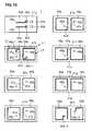
- FIG. 12includes plan views showing a layered structure of the feed circuit board.
- FIG. 13is a perspective view of an example in which the coupling electrode is provided on the feed circuit board.
- FIG. 14is a perspective view schematically showing the structure of a wireless IC device according to a sixth preferred embodiment of the present invention.
- FIG. 15is a perspective view showing the wireless IC device according to the sixth preferred embodiment of the present invention.
- FIG. 16is a cross-sectional view showing a modification of the wireless IC device according to a preferred embodiment of the present invention.
- FIGS. 17A and 17Bare diagrams showing a wireless IC device component according to a seventh preferred embodiment of the present invention, where FIG. 17A is a perspective view and FIG. 17B is a developed view of a coupling electrode.
- FIG. 18is a perspective view showing a wireless IC device component according to an eighth preferred embodiment of the present invention.
- FIGS. 19A and 19Bare diagrams showing a wireless IC device component according to a ninth preferred embodiment of the present invention, where FIG. 19A is a cross-sectional view and FIG. 19B is a perspective view of a coupling electrode.
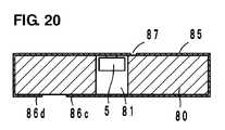
- FIG. 20is a cross-sectional view showing a wireless IC device component according to a tenth preferred embodiment.
- the wireless IC devicepreferably includes a radiation plate and the wireless IC device component is defined as the wireless IC device with the radiation plate being omitted.
- the radiation plateis preferably provided at the side of an article and the wireless IC device component is coupled to the radiation plate to define the wireless IC device.
- the same reference numeralsare used in the drawings to identify the same or substantially the same components and portions. A duplicated description of such components and portions is omitted herein.
- a wireless IC devicepreferably includes a wireless IC chip 5 arranged to process transmission and reception signals having certain frequencies, a radiation plate 115 provided on a base 110 , such as a polyethylene terephthalate (PET) film, for example, and a coupling electrode 125 provided on a base (not shown), such as a PET film, for example, as shown in FIG. 1 .
- a radiation plate 115provided on a base 110 , such as a polyethylene terephthalate (PET) film, for example
- PETpolyethylene terephthalate
- the coupling electrode 125preferably includes a pair of coupling portions 126 a and 126 b to be coupled to the wireless IC chip 5 and a pair of opposing ends 126 c and 126 d defined by a cutout of the coupling electrode 125 .
- the wireless IC chip 5preferably includes, for example, a clock circuit, a logic circuit, and a memory circuit. Necessary information is stored in the wireless IC chip 5 .
- a pair of input-output terminal electrodes(not shown) is provided on the rear surface of the wireless IC chip 5 .
- the pair of input-output terminal electrodesis mounted on the pair of coupling portions 126 a and 126 b of the coupling electrode 125 via a conductive adhesive or other suitable adhesive, for example.
- the radiation plate 115preferably includes, for example, a metal laminate made of a conductive material, such as an aluminum foil or a copper foil, that is provided on substantially the entire surface of the base 110 .
- the coupling electrode 125is preferably arranged so as to be substantially perpendicular to the radiation plate 115 with the opposing ends 126 c and 126 d being opposed to the radiation plate 115 .
- the opposing end 126 cis opposed to the opposing end 126 d so as to be capacitively coupled to the opposing end 126 d , so that the coupling electrode 125 electrically forms an annular electrode.
- a lower-side portion of the coupling electrode 125 including the opposing ends 126 c and 126 dis capacitively and magnetically coupled to the radiation plate 115 .
- the radiation plate 115may preferably be provided as a portion of an article, for example, without being combined with the coupling electrode 125 in advance.
- the coupling electrode 125has a certain length from the coupling portions 126 a and 126 b to the opposing ends 126 c and 126 d , has a certain resonant frequency corresponding to the electrical length, and also functions as a matching portion arranged to perform phase matching.
- the coupling electrode 125performs impedance matching between the wireless IC chip 5 and the radiation plate 115 .
- a transmission signal that is sent from the wireless IC chip 5 and that has a certain frequencyis transmitted to the radiation plate 115 via the coupling electrode 125 , and a signal having a certain frequency is selected by the coupling electrode 125 from signals received by the radiation plate 115 and the selected signal is supplied to the wireless IC chip 5 . Accordingly, in the wireless IC device, the wireless IC chip 5 is operated with the signal received by the radiation plate 115 and the response signal from the wireless IC chip 5 is externally radiated from the radiation plate 115 .
- the capacitive and magnetic coupling between the coupling electrode 125 and the radiation plate 115causes the wireless IC chip 5 to be coupled to the radiation plate 115 so as to establish communication between the wireless IC chip 5 and an RFID system in a non-contact manner.
- Energyis transmitted between the coupling electrode 125 and the radiation plate 115 primarily through the magnetic coupling.
- the opposing ends 126 c and 126 d of the coupling electrode 125are opposed to the radiation plate so as to be capacitively coupled to the radiation plate. Such capacitive coupling causes the opposing ends 126 c and 126 d of the coupling electrode 125 to be electrically connected to each other via the radiation plate 115 to electrically form an annular electrode.
- the coupling electrode 125has an inductive reactance (XL: j ⁇ L) caused by the electrical length and a capacitive reactance (XC: 1/j ⁇ C) caused by the coupling electrode 125 and the radiation plate 115 . Since the inductive reactance has a phase opposite to that of the capacitive reactance, the impedance does not significantly increase because of the increase in the electrical length of the coupling electrode 125 . In other words, it is possible to achieve the impedance matching between the wireless IC chip 5 and the radiation plate 115 even if the electrical length of the coupling electrode 125 is increased. Thus, the electrical length of the coupling electrode 125 can be increased to strengthen the magnetic coupling between the coupling electrode 125 and the radiation plate 115 .
- the coupling electrode 125is preferably arranged such that a loop surface of the coupling electrode 125 , that is, a surface of the coupling electrode 125 on which the wireless IC chip 5 is disposed, is perpendicular or substantially perpendicular to the radiation plate 115 so as to produce a magnetic field parallel to the radiation plate 115 . Consequently, an electric field perpendicular or substantially perpendicular to the radiation plate 115 is produced, a magnetic field is induced by the electric-field loop, and this chain expands the electromagnetic-field distribution. As a result, the wireless IC device is functional even if the wireless IC device is arranged on the metal surface. In addition, it is also possible to cause the metal surface to function as the radiation plate.
- FIG. 2schematically illustrates an example of the electromagnetic-field distribution produced by the coupling electrode 125 (magnetic fields H are indicated by broken lines and electric fields E are indicated by fine lines).
- the annular coupling electrode 125functions as a magnetic-field antenna.
- the coupling electrode 125causes the magnetic fields H to induce the electric fields E perpendicular or substantially perpendicular to the radiation plate 115 , the electric fields E induce the magnetic fields H, and this chain expands the electromagnetic-field distribution.
- the coupling electrode 125is described as the transmission antenna, the coupling electrode 125 similarly operates as a reception antenna due to the reversibility of the antenna.
- an electromagnetic fieldinduces a magnetic field H
- the magnetic field Hinduces an electric field E perpendicular or substantially perpendicular to the surface of the radiation plate 115
- the electric field Eproduce a magnetic field H parallel or substantially parallel to the surface of the radiation plate 115 , which are coupled to the coupling electrode 125 .
- the wireless IC device componentis functional even if a component on which the wireless IC device component is mounted is made of a metal, and the wireless IC device component similarly operates even if a component on which the wireless IC device component is mounted is an article made of a material other than metal, for example, an electrolyte such as blood, soybean paste, saline solution, or soapy water.
- an electrolytesuch as blood, soybean paste, saline solution, or soapy water.
- the wireless IC devicecan preferably use, for example, frequencies within an ultra high frequency (UHF) band (850 MHz to 970 MHz).
- UHFultra high frequency
- the wireless IC devicesince the resonant frequency of a signal is set by the coupling electrode 125 in the wireless IC device of the first preferred embodiment, the wireless IC device operates as it is even if the wireless IC device is mounted on various articles. Accordingly, variations in the radiation characteristics are prevented or minimized and it is not necessary to change the design of, for example, the radiation plate 115 for each article upon which the wireless IC device is to be mounted.
- the frequency of a transmission signal radiated from the radiation plate 115 and the frequency of a reception signal to be supplied to the wireless IC chip 5substantially correspond to the resonant frequency of the coupling electrode 125 .
- the frequencies of the transmission and reception signalsare determined in the coupling electrode 125 , the frequency characteristics do not vary such that stable frequency characteristics are achieved, regardless of the shape, the size, and/or the arrangement relationship of the radiation plate 115 , for example, even if the wireless IC device is rounded or is sandwiched between dielectric materials.
- a wireless IC device componentpreferably includes a coupling electrode 135 , as shown in FIGS. 3A and 3B .
- the coupling electrode 135preferably includes a pair of coupling portions 136 a and 136 b arranged to be coupled to the wireless IC chip 5 and a pair of opposing ends 136 c and 136 d .
- the opposing ends 136 c and 136 dare capacitively coupled to each other.
- the opposing end 136 cis capacitively coupled to the opposing end 136 d , so that the coupling electrode 135 electrically forms an annular electrode and functions as a magnetic-field antenna.
- the wireless IC device componentfunctions as a wireless IC device with the coupling electrode 135 being coupled to the radiation plate 115 , similarly to the coupling electrode 125 shown in the first preferred embodiment.
- the coupling electrode 135has an inductive reactance (XL: j ⁇ L) caused by the electrical length and a capacitive reactance (XC: 1/j ⁇ C) caused by the paired opposing ends 136 c and 136 d that are capacitively coupled to each other. Since the inductive reactance has a phase opposite to that of the capacitive reactance, the impedance does not significantly increase because of the increase in the electrical length of the coupling electrode 135 . In other words, it is possible to achieve the impedance matching between the wireless IC chip 5 and the radiation plate 115 even if the electrical length of the coupling electrode 135 is increased. Thus, the electrical length of the coupling electrode 135 may be increased to strengthen the magnetic coupling between the coupling electrode 135 and the radiation plate 115 .
- the wireless IC device componentfunctions as the wireless IC device even if the wireless IC device component is arranged on the metal surface.
- a wireless IC device componentpreferably includes a coupling electrode 145 having a U-shape in a side view, as shown in FIG. 4 .
- the coupling electrode 145is preferably provided from the front surface of a base (not shown) made of resin, for example, to the rear surface thereof and includes an opening 147 and a slit 148 extending to the opening 147 on its surface.
- the opening 147 and the slit 148define a pair of coupling portions 146 a and 146 b to be coupled to the wireless IC chip 5 .
- the coupling electrode 145includes opposing ends 146 c and 146 d .
- the opposing ends 146 c and 146 dare capacitively coupled to each other.
- the opposing end 146 cis capacitively coupled to the opposing end 146 d , so that the coupling electrode 145 electrically forms an annular electrode, functions as a magnetic-field antenna, and is coupled to the radiation plate 115 .
- the operational effects of the third preferred embodimentare similar to those of the second preferred embodiment.
- the difference in voltage between the opposing ends 146 c and 146 dis relatively large in the coupling electrode 145 of the third preferred embodiment, such that the opposing end 146 c can be capacitively coupled to the opposing end 146 d even if the opposing end 146 c is a certain distance apart from the opposing end 146 d.
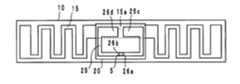
- a wireless IC devicepreferably includes the wireless IC chip 5 arranged to process transmission and reception signals having certain frequencies, a radiation plate 15 provided on a base 10 , such as a PET film, for example, and a coupling electrode 25 provided on a base 20 , such as a PET film, for example, as shown in FIGS. 5A and 5B .
- the coupling electrode 25preferably includes a pair of coupling portions 26 a and 26 b arranged to be coupled to the wireless IC chip 5 and a pair of opposing ends 26 c and 26 d defined by a cutout of the coupling electrode 25 .
- the wireless IC chip 5preferably includes, for example, a clock circuit, a logic circuit, and a memory circuit. Necessary information is stored in the wireless IC chip 5 .
- a pair of input-output terminal electrodes(not shown) is provided on the rear surface of the wireless IC chip 5 .
- the pair of input-output terminal electrodesis mounted on the pair of coupling portions 26 a and 26 b of the coupling electrode 25 via a conductive adhesive 6 in a manner shown in FIG. 6 .
- the radiation plate 15preferably has a dipole shape extending toward both ends in a meandering pattern, for example, and includes a midsection 15 a of the radiation plate 15 is overlapped with the opposing ends 26 c and 26 d of the coupling electrode 25 to be capacitively coupled to the opposing ends 26 c and 26 d .
- the capacitive coupling between the opposing ends 26 c and 26 d and the radiation plate 15causes the opposing ends 26 c and 26 d to be electrically connected to each other via the radiation plate 15 and, thus, the coupling electrode 25 defines an annular electrode.
- the radiation plate 15 and the coupling electrode 25are each preferably provided by attaching a metal thin film made of a conductive material, such as an aluminum foil or a copper foil, for example, on the bases 10 and 20 to form a pattern, applying a conductive paste made of, for example, Al, Cu, or Ag on the bases 10 and 20 , or forming a pattern on a film provided by plating.
- a metal thin film made of a conductive materialsuch as an aluminum foil or a copper foil
- the coupling electrode 25preferably has a certain length from the coupling portions 26 a and 26 b to the opposing ends 26 c and 26 d , has a certain resonant frequency corresponding to the electrical length, and also functions as a matching portion arranged to perform the phase matching.
- the radiation plate 15also has a certain resonant frequency corresponding to the electrical length of the radiation plate 15 .
- the coupling electrode 25performs the impedance matching between the wireless IC chip 5 and the radiation plate 15 .
- a transmission signal that is sent from the wireless IC chip 5 and that has a certain frequencyis transmitted to the radiation plate 15 via the coupling electrode 25 , and a signal having a certain frequency is selected by the coupling electrode 25 from signals received by the radiation plate 15 and the selected signal is supplied to the wireless IC chip 5 .
- the wireless IC chip 5is operated with the signal received by the radiation plate 15 and the response signal from the wireless IC chip 5 is externally radiated from the radiation plate 15 .
- the capacitive coupling between the coupling electrode 25 and the radiation plate 15causes the wireless IC chip 5 to be coupled to the radiation plate 15 to establish the communication between the wireless IC chip 5 and an RFID system in a non-contact manner.
- Energyis transmitted between the coupling electrode 25 and the radiation plate 15 primarily through the magnetic coupling.
- the coupling electrode 25has an inductive reactance (XL: j ⁇ L) caused by the electrical length and a capacitive reactance (XC: 1/j ⁇ C) caused by the coupling electrode 25 and the radiation plate 15 . Since the inductive reactance has a phase opposite to that of the capacitive reactance, the impedance does not significantly increase because of the increase in the electrical length of the coupling electrode 25 . In other words, it is possible to achieve the impedance matching between the wireless IC chip 5 and the radiation plate 15 even if the electrical length of the coupling electrode 25 is increased.
- the impedance matchingis preferably performed by setting a reactance between the wireless IC chip 5 and one terminal of the coupling electrode 25 and also setting a reactance between the other terminal of the coupling electrode 25 and the radiation plate 15 so as to have a complex conjugate relationship.
- the coupling electrode 25is capacitively coupled to the radiation plate 15 to provide the capacitive reactance, it is necessary for the coupling electrode 25 to have a relatively larger inductive reactance in order to achieve a certain impedance and the electrical length of the coupling electrode 25 is increased.
- the longer electrical lengthcauses the coupling electrode 25 to receive an increased amount of magnetic field from the radiation plate 15 and, thus, the magnetic coupling between the coupling electrode 25 and the radiation plate 15 is further strengthened.
- the coupling electrode 25is capacitively coupled to the radiation plate 15 via the opposing ends 26 c and 26 d , the mounting accuracy of the coupling electrode 25 on the radiation plate 15 is not strictly limited.
- a portion of the signals from the coupling electrodeis externally radiated from the wireless IC device as the magnetic field and signals are also externally radiated from the radiation plate 15 as the electric field.
- Designing the coupling electrode 25 so as to have a resonant frequency lower than the resonant frequency of the radiation plate 15enables the radiation characteristics to be broadened.
- the radiation plate 15is capable of long-range communication by using the electric field and the coupling electrode 25 is capable of short-range communication by using the magnetic field.
- the coupling electrode 25since three sides of the coupling electrode 25 are preferably arranged relatively close to the radiation plate 15 and secondary electromagnetic coupling occurs at the proximity portion, the coupling between the coupling electrode 25 and the radiation plate 15 can be further strengthened. Consequently, it is possible to improve the radiation gain of the wireless IC device and to further broaden the radiation characteristics thereof.
- the wireless IC devicesince the resonant frequency of a signal is set in the coupling electrode 25 in the wireless IC device, the wireless IC device operates properly even if the wireless IC device is mounted on various articles. Accordingly, variations in the radiation characteristics are prevented or minimized and it is not necessary to change the design of, for example, the radiation plate 15 for each article upon which the wireless IC device is to be mounted.
- the frequency of a transmission signal radiated from the radiation plate 15 and the frequency of a reception signal to be supplied to the wireless IC chip 5substantially correspond to the resonant frequency of the coupling electrode 25 .
- the frequencies of transmission and reception signalsare determined in the coupling electrode 25 , the frequency characteristics do not vary to achieve stable frequency characteristics, regardless of the shape, the size, and/or the arrangement relationship of the radiation plate 15 , for example, even if the wireless IC device is rounded or is sandwiched between dielectric materials.
- the shape of the radiation plate 15is not limited to the dipole shape and a radiation plate 65 having an increased area shown in a sixth preferred embodiment of the present invention described below (refer to FIGS. 14 and 15 ) may be used.
- the base 20is attached on the radiation plate 65 .
- the radiation plate 65may be a portion of an article.
- the midsection 15 a of the radiation plate 15may be narrower or wider than the width shown in FIG. 5 .
- the coupling electrode 25may be shifted leftward or rightward with respect to the central portion of the radiation plate 15 .
- the coupling electrode 25may have various shapes including an elliptical or substantially elliptical shape, for example, instead of the rectangular or substantially rectangular shape in the fourth preferred embodiment.
- the coupling electrode 25may be bent into multiple portions, for example, as shown in FIG. 7 . The same applies to other preferred embodiments of the present invention described herein.
- the coupling electrode 25may be arranged so as to be perpendicular or substantially perpendicular to the radiation plate 15 , as shown in FIG. 8 , and the pair of opposing ends 26 c and 26 d may be capacitively coupled to the radiation plate 15 .
- the arrangement of the loop surface of the coupling electrode 25 so as to be perpendicular or substantially perpendicular to the radiation plate 15 in the above mannercauses a magnetic field parallel or substantially parallel to the radiation plate 15 to be produced. Consequently, an electric field perpendicular or substantially perpendicular to the radiation plate 15 is produced, a magnetic-field loop is induced by the electric-field loop, and this chain expands the electromagnetic-field distribution.
- the wireless IC deviceis functional even if the wireless IC device is arranged on the metal surface.
- the opposing ends 26 c and 26 d of the coupling electrode 25may be opposed to the metal surface to be capacitively coupled to the metal surface so as to cause the metal surface to function as the radiation plate 15 .
- the wireless IC chip 5may preferably be installed on a feed circuit board 1 , as shown in FIGS. 9A and 9B .
- An example in which the wireless IC chip 5 is installed on the feed circuit board 1is described as a fifth preferred embodiment of the present invention.
- the radiation plate 15preferably including the meandering pattern described in the fourth preferred embodiment or the radiation plate 65 having a larger area described below in the sixth preferred embodiment, for example, may preferably be used as the radiation plate, although not shown.
- the opposing ends of the coupling electrode 25are capacitively coupled to the radiation plate 15 or 65 .
- the feed circuit board 1preferably includes a feed circuit 11 (described in detail below with reference to FIG. 12 ) including a resonant circuit and/or a matching circuit including inductance elements L 1 and L 2 that have opposite phases and that are magnetically coupled to each other (denoted by a mutual inductance M), as shown as an equivalent circuit in FIG. 10 .
- a feed circuit 11(described in detail below with reference to FIG. 12 ) including a resonant circuit and/or a matching circuit including inductance elements L 1 and L 2 that have opposite phases and that are magnetically coupled to each other (denoted by a mutual inductance M), as shown as an equivalent circuit in FIG. 10 .
- input-output terminal electrodesare preferably electrically connected to one end of a feed terminal electrode 42 a provided on the feed circuit board 1 and to one end of a feed terminal electrode 42 b provided thereon, and mounting terminal electrodes are preferably electrically connected to mounting electrodes 43 a and 43 b via metallic bumps or other suitable structure, for example, as shown in FIG. 11 .
- the inductance elements L 1 and L 2 included in the feed circuit 11have opposite phases and are magnetically coupled to each other to resonate with the frequency processed by the wireless IC chip 5 and to be electromagnetically coupled to the coupling portions 26 a and 26 b of the coupling electrode 25 .
- the feed circuit 11performs the impedance matching between the wireless IC chip 5 and the radiation plate 15 .
- the feed circuit 11transmits a transmission signal that is sent from the wireless IC chip 5 and that has a certain frequency to the radiation plate 15 via the coupling electrode 25 , and the feed circuit 11 selects a signal having a certain frequency from signals that are received by the radiation plate 15 and that are supplied via the coupling electrode 25 and supplies the selected signal to the wireless IC chip 5 .
- the wireless IC chip 5is operated with the signal received by the radiation plate 15 and the response signal from the wireless IC chip 5 is externally radiated from the radiation plate 15 .
- the resonant frequency of the feed circuit 11substantially corresponds to the frequency of a signal transmitted or received via the radiation plate 15 .
- the effects of the coupling electrode 25are the same or substantially the same as those described in the fourth preferred embodiment, and the operational effects of the fifth preferred embodiment are similar to those of the fourth preferred embodiment.
- the feed circuit board 1is preferably manufactured by stacking, pressure-bonding, and firing ceramic sheets 41 a to 41 h , each of which is made of a dielectric material or a magnetic material, for example.
- the top sheet 41 aincludes the feed terminal electrodes 42 a and 42 b , the mounting electrodes 43 a and 43 b , via-hole conductors 44 a , 44 b , 45 a , and 45 b provided thereon.
- the second to eight sheets 41 b to 41 heach include line electrodes 46 a and 46 b provided thereon, which define the inductance elements L 1 and L 2 .
- the second to eighth sheets 41 b to 41 heach include via-hole conductors 47 a , 47 b , 48 a , and 48 b , as required.
- Stacking the sheets 41 a to 41 hprovides the inductance element L 1 in which the line electrodes 46 a are spirally connected via the via-hole conductor 47 a and provides the inductance element L 2 in which the line electrodes 46 b are spirally connected via the via-hole conductor 47 b .
- a capacitanceis produced between the line electrodes 46 a and 46 b.
- An end 46 a - 1 of the line electrode 46 a on the sheet 41 bis connected to the feed terminal electrode 42 a via the via-hole conductor 45 a
- an end 46 a - 2 of the line electrode 46 a on the sheet 41 his connected to the feed terminal electrode 42 b via the via-hole conductors 48 a and 45 b
- An end 46 b - 1 of the line electrode 46 b on the sheet 41 bis connected to the feed terminal electrode 42 b via the via-hole conductor 44 b
- an end 46 b - 2 of the line electrode 46 b on the sheet 41 his connected to the feed terminal electrode 42 a via the via-hole conductors 48 b and 44 a.
- the magnetic field produced in the inductance element L 1is offset by the magnetic field produced in the inductance element L 2 . Since the magnetic fields are offset, it is necessary for the line electrodes 46 a and 46 b to have an increased length in order to achieve a desired inductance value. Increasing the length of the line electrodes 46 a and 46 b decreases the Q value so as to eliminate or reduce the steepness of the resonance characteristics, thus broadening the resonant characteristics near the resonant frequency.
- the inductance elements L 1 and L 2are provided at different leftward and rightward positions in a perspective plan view of the feed circuit board 1 .
- the magnetic fields produced by the inductance elements L 1 and L 2have opposite directions. Accordingly, coupling the feed circuit to the coupling portions 26 a and 26 b of the coupling electrode 25 causes currents in opposite directions to be excited in the coupling portions 26 a and 26 b to allow transmission and reception of signals to and from the radiation plate 15 via the coupling electrode 25 .
- the coupling electrode 25may preferably be provided on the rear surface of the feed circuit board 1 , as shown in FIG. 13 .
- the coupling electrode 25is arranged so as to be opposed to the radiation plate 15 or the radiation plate 65 to capacitively couple the opposing ends 26 c and 26 d to the radiation plate 15 .
- the coupling electrode 25may be arranged so as to be perpendicular or substantially perpendicular to the radiation plate 15 or 65 .
- the feed circuit board 1may preferably be a flexible board, for example.
- the flexible board 1may be used to attach the board 1 along a curved surface of an article.
- the radiation plate 15is provided as a portion of an article, it is possible to couple the coupling electrode 25 without flexure even if the board 1 is attached along a curved surface of an article because the opposing ends 26 c and 26 d opposing the radiation plate 15 are spaced apart from each other on one surface of the feed circuit board 1 .
- a coupling electrode 55is provided along surfaces of a flexible dielectric substrate 50 preferably made of polyurethane, for example, which is a wide band, as schematically shown in FIG. 14 and as shown in detail in FIG. 15 .
- the wireless IC chip 5(or the feed circuit board 1 on which the wireless IC chip 5 is mounted) is preferably mounted on a pair of coupling portions 56 a and 56 b .
- a pair of opposing portions 56 c and 56 doppose the broad radiation plate 65 provided on the rear surface of a base 60 preferably made of a dielectric material, for example, to be capacitively coupled to the radiation plate 65 .
- the capacitive coupling between the opposing ends 56 c and 56 d and the radiation plate 65causes the opposing ends 56 c and 56 d to be electrically connected to each other via the radiation plate 65 and, thus, the coupling electrode 55 defines an annular electrode.
- arranging the loop surface of the coupling electrode 55 so as to be perpendicular or substantially perpendicular to the radiation plate 65enables the wireless IC device to be arranged on the metal surface.
- the metal surfacemay be caused to function as the radiation plate.
- the opposing ends 56 c and 56 d of the coupling electrode 55oppose the radiation plate 65 via the base 60 preferably made of a dielectric material, for example, to be capacitively coupled to the radiation plate 65 .
- the operational effects of the sixth preferred embodimentare the same or substantially the same as the ones described in the first preferred embodiment.
- the base 60 and the radiation plateare not necessarily defined by dedicated components of the wireless IC device and may be defined by portions of an article to which the dielectric substrate 50 of the coupling electrode 55 is attached.
- the radiation plate 65may be, for example, a ground electrode of an electric device or an electronic device made of metal.
- the coupling electrode 55can be easily curved and, thus, can be attached along a curved surface of an article.
- the coupling electrode 55may preferably be incorporated into the feed circuit board 1 shown in the fifth preferred embodiment, along with the feed circuit 11 , as shown in FIG. 16 .
- the coupling electrode 55may preferably be provided on the rear surface of the feed circuit board 1 .
- the opposing ends 56 c and 56 d of the coupling electrode 55are capacitively coupled to the radiation plate 65 via the dielectric layers of the board 1 .
- the coupling electrode 55may be adhered to the radiation plate 65 with a non-conductive adhesive, for example, to capacitively couple the coupling electrode 55 to the radiation plate 65 .
- a coupling electrode 75is preferably provided along a flexible dielectric substrate (not shown) made of polyurethane, for example, which is a wide band, as shown in FIGS. 17A and 17B .
- the wireless IC chip 5(or the feed circuit board on which the wireless IC chip 5 is mounted) is preferably mounted on a pair of coupling portions 76 a and 76 b .
- the coupling electrode 75includes a pair of opposing ends 76 c and 76 d . The opposing ends 76 c and 76 d are overlapped with each other on the rear surface of a base to be capacitively coupled to each other.
- the opposing end 76 cis capacitively coupled to the opposing end 76 d , so that the coupling electrode 75 electrically forms an annular electrode and functions as a magnetic-field antenna.
- the wireless IC device componentfunctions as a wireless IC device with the coupling electrode 75 being coupled to the radiation plate.
- the operational effects of the seventh preferred embodimentare similar to those of the second preferred embodiment.
- arranging the loop surface of the coupling electrode 75 so as to be perpendicular or substantially perpendicular to the radiation plateenables the wireless IC device to be arranged on the metal surface.
- the metal surfacemay function as the radiation plate.
- a coupling electrode 85is preferably provided along a flexible dielectric substrate 80 from the top surface of the substrate 80 to the bottom surface thereof via left and right end surfaces thereof, as shown in FIG. 18 .
- the coupling electrode 85has a longitudinal direction and a latitudinal direction in a plan view, and a slit 87 having a flexion is provided at a substantially central portion of the top surface.
- a pair of coupling portions 86 a and 86 bis preferably opposed to each other in the latitudinal direction at a central portion of the slit 87 , and the feed circuit board 1 (refer to FIG. 11 and FIG.
- the wireless IC chip 5is preferably sealed with a resin material 7 , for example.
- the wireless IC chip 5may be directly mounted on the coupling portions 86 a and 86 b.
- a pair of opposing ends 86 c and 86 dis adjacent to a slit 88 at a central portion of the bottom surface of the dielectric substrate 80 .
- the opposing end 86 cis capacitively coupled to the opposing end 86 d , so that the coupling electrode 85 electrically forms an annular electrode and functions as a magnetic-field antenna.
- the wireless IC device componentfunctions as a wireless IC device with the coupling electrode 85 being coupled to the radiation plate.
- the coupling electrode 85includes the longitudinal direction and the latitudinal direction in a plan view and the coupling portion 86 a opposes the coupling portion 86 b in the latitudinal direction in the eighth preferred embodiment. Accordingly, even if the coupling electrode 85 is flexed (the flexible dielectric substrate 80 is likely to be flexed in the longitudinal direction), it is possible to prevent the board 1 and the wireless IC chip 5 from being destroyed or separated from one another due to the flexural stress applied to the feed circuit board 1 and the wireless IC chip 5 .
- a wireless IC device component according to a ninth preferred embodiment of the present inventionhas the same or substantially the same configuration as that of the eighth preferred embodiment, as shown in FIGS. 19A and 19B .
- the wireless IC device component of the ninth preferred embodimentdiffers from the wireless IC device component of the eighth preferred embodiment in that the coupling portions 86 a and 86 b are preferably arranged at positions different from those of the pair of opposing ends 86 c and 86 d in a plan view.
- the wireless IC chip 5may be directly mounted on the coupling portions 86 a and 86 b or the feed circuit board 1 on which the wireless IC chip 5 is mounted may be mounted on the coupling portions 86 a and 86 b , as shown in the eighth preferred embodiment.
- the operational effects of the ninth preferred embodimentare similar to those of the eighth preferred embodiment. Since the opposing ends 86 c and 86 d are defined by a cutout portion of the coupling electrode 85 , the dielectric substrate 80 is likely to be bent at this cutout portion. In the ninth preferred embodiment, since the opposing ends 86 c and 86 d are arranged at positions different from those of the coupling portions 86 a and 86 b in a plan view, the bending stress occurring at the opposing ends 86 c and 86 d is prevented from being transmitted to the coupling portions 86 a and 86 b . Accordingly, it is possible to suppress the effect of the bending stress on the wireless IC chip 5 and the feed circuit board 1 mounted on the coupling portions 86 a and 86 b.
- a through hole 81is preferably provided at a substantially central portion of the dielectric substrate 80 , the wireless IC chip 5 is disposed in the hole 81 , and the wireless IC chip 5 is coupled to the coupling portions 86 a and 86 b bordering on the hole 81 , as shown in FIG. 20 .
- the feed circuit board 1may be mounted in the coupling portions 86 a and 86 b in a state in which the feed circuit board 1 is disposed in the hole 81 .
- the structure of the coupling electrode 85 in the tenth preferred embodimentis similar to the structure thereof in the ninth preferred embodiment. Accordingly, the operational effects of the tenth preferred embodiment are similar to those of the ninth preferred embodiment.
- the wireless IC chip 5is incorporated in the dielectric substrate 80 , it is possible to protect the wireless IC chip 5 from an external impact and to reduce the size of the wireless IC device component.
- the opposing ends 86 c and 86 dare preferably arranged at positions different from those of the coupling portions 86 a and 86 b in a plan view, the bottom face side of the hole 81 on which the coupling portions 86 a and 86 b border is sealed with the coupling electrode 85 .
- the holemay be a cavity (a housing portion) having a size sufficient to house the wireless IC chip 5 , instead of the through hole.
- the wireless IC device component and the wireless IC device according to the present inventionare not limited to the preferred embodiments described above, and various changes and modifications may be made to the present invention without departing from the spirit and scope thereof.
- the materials of the radiation plate and the base shown in the above preferred embodimentsare only examples, and the radiation plate and the base may be made of an arbitrary material as long as the material has necessary characteristics. Processing other than the metal bumping may be used to connect the wireless IC chip to the electrodes.
- the wireless ICmay be manufactured as an element in the feed circuit board.
- the provision of the wireless IC in the feed circuit boardeliminates parasitic components in the portion in which the wireless IC is connected to the feed circuit to improve the characteristics of the wireless IC device.
- the height of the wireless IC devicecan be reduced.
- the shape and/or arrangement of the portion at which the feed circuit is coupled to the coupling electrodecan be changed to cause the feed circuit to be coupled to the coupling electrode only through the electric field or the magnetic field.
- the coupling portionsmay not be defined by a pair of ends and may be linear portions as long as the wireless IC or the feed circuit can be coupled to the coupling portions.
- the pair of opposing ends of the coupling electrode or the opposing ends opposing the radiation platemay be capacitively coupled to each other via another electrode.
- preferred embodiments of the present inventionare useful for the wireless IC device components and the wireless IC devices and, in particular, preferred embodiments of the present invention are excellent in that the coupling electrode can be more satisfactorily coupled to the radiation plate.
Landscapes
- Engineering & Computer Science (AREA)
- Microelectronics & Electronic Packaging (AREA)
- Computer Hardware Design (AREA)
- Physics & Mathematics (AREA)
- General Physics & Mathematics (AREA)
- Theoretical Computer Science (AREA)
- Details Of Aerials (AREA)
Abstract
Description
Claims (14)
Priority Applications (2)
| Application Number | Priority Date | Filing Date | Title |
|---|---|---|---|
| US13/794,929US8690070B2 (en) | 2009-04-14 | 2013-03-12 | Wireless IC device component and wireless IC device |
| US14/151,852US8876010B2 (en) | 2009-04-14 | 2014-01-10 | Wireless IC device component and wireless IC device |
Applications Claiming Priority (5)
| Application Number | Priority Date | Filing Date | Title |
|---|---|---|---|
| JP2009-098437 | 2009-04-14 | ||
| JP2009098437 | 2009-04-14 | ||
| JP2009-187318 | 2009-08-12 | ||
| JP2009187318 | 2009-08-12 | ||
| PCT/JP2010/056559WO2010119854A1 (en) | 2009-04-14 | 2010-04-13 | Component for wireless ic device and wireless ic device |
Related Parent Applications (1)
| Application Number | Title | Priority Date | Filing Date |
|---|---|---|---|
| PCT/JP2010/056559ContinuationWO2010119854A1 (en) | 2009-04-14 | 2010-04-13 | Component for wireless ic device and wireless ic device |
Related Child Applications (1)
| Application Number | Title | Priority Date | Filing Date |
|---|---|---|---|
| US13/794,929ContinuationUS8690070B2 (en) | 2009-04-14 | 2013-03-12 | Wireless IC device component and wireless IC device |
Publications (2)
| Publication Number | Publication Date |
|---|---|
| US20120006904A1 US20120006904A1 (en) | 2012-01-12 |
| US8418928B2true US8418928B2 (en) | 2013-04-16 |
Family
ID=42982516
Family Applications (3)
| Application Number | Title | Priority Date | Filing Date |
|---|---|---|---|
| US13/241,823ActiveUS8418928B2 (en) | 2009-04-14 | 2011-09-23 | Wireless IC device component and wireless IC device |
| US13/794,929ActiveUS8690070B2 (en) | 2009-04-14 | 2013-03-12 | Wireless IC device component and wireless IC device |
| US14/151,852ActiveUS8876010B2 (en) | 2009-04-14 | 2014-01-10 | Wireless IC device component and wireless IC device |
Family Applications After (2)
| Application Number | Title | Priority Date | Filing Date |
|---|---|---|---|
| US13/794,929ActiveUS8690070B2 (en) | 2009-04-14 | 2013-03-12 | Wireless IC device component and wireless IC device |
| US14/151,852ActiveUS8876010B2 (en) | 2009-04-14 | 2014-01-10 | Wireless IC device component and wireless IC device |
Country Status (3)
| Country | Link |
|---|---|
| US (3) | US8418928B2 (en) |
| JP (4) | JP5510450B2 (en) |
| WO (1) | WO2010119854A1 (en) |
Cited By (3)
| Publication number | Priority date | Publication date | Assignee | Title |
|---|---|---|---|---|
| US20130200163A1 (en)* | 2009-04-14 | 2013-08-08 | Murata Manufacturing Co., Ltd. | Wireless ic device component and wireless ic device |
| US20180123242A1 (en)* | 2016-10-28 | 2018-05-03 | Samsung Electronics Co., Ltd. | Antenna device and electronic device including the same |
| US11101561B2 (en)* | 2017-09-08 | 2021-08-24 | Murata Manufacturing Co., Ltd. | Dual band compatible antenna device |
Families Citing this family (57)
| Publication number | Priority date | Publication date | Assignee | Title |
|---|---|---|---|---|
| US8235299B2 (en) | 2007-07-04 | 2012-08-07 | Murata Manufacturing Co., Ltd. | Wireless IC device and component for wireless IC device |
| CN102915462B (en) | 2007-07-18 | 2017-03-01 | 株式会社村田制作所 | Wireless IC device |
| EP2251934B1 (en) | 2008-03-03 | 2018-05-02 | Murata Manufacturing Co. Ltd. | Wireless ic device and wireless communication system |
| EP2284949B1 (en) | 2008-05-21 | 2016-08-03 | Murata Manufacturing Co. Ltd. | Wireless ic device |
| WO2009145007A1 (en) | 2008-05-26 | 2009-12-03 | 株式会社村田製作所 | Wireless ic device system and method for authenticating wireless ic device |
| JP4605318B2 (en) | 2008-11-17 | 2011-01-05 | 株式会社村田製作所 | Antenna and wireless IC device |
| EP2385580B1 (en) | 2009-01-30 | 2014-04-09 | Murata Manufacturing Co., Ltd. | Antenna and wireless ic device |
| EP2568534A3 (en) | 2009-04-21 | 2014-05-14 | Murata Manufacturing Co., Ltd. | Antenna devie and method of setting resonant frequency of antenna device |
| JP5201270B2 (en) | 2009-09-30 | 2013-06-05 | 株式会社村田製作所 | Circuit board and manufacturing method thereof |
| JP5304580B2 (en) | 2009-10-02 | 2013-10-02 | 株式会社村田製作所 | Wireless IC device |
| JP5327334B2 (en) | 2009-11-04 | 2013-10-30 | 株式会社村田製作所 | Communication terminal and information processing system |
| US8484395B2 (en)* | 2010-01-27 | 2013-07-09 | Broadcom Corporation | System and method for dynamically configuring processing resources and memory resources of wireless-enabled components |
| WO2011108340A1 (en) | 2010-03-03 | 2011-09-09 | 株式会社村田製作所 | Wireless communication module and wireless communication device |
| JP5370581B2 (en) | 2010-03-24 | 2013-12-18 | 株式会社村田製作所 | RFID system |
| WO2011122163A1 (en) | 2010-03-31 | 2011-10-06 | 株式会社村田製作所 | Antenna and wireless communication device |
| GB2537773A (en) | 2010-07-28 | 2016-10-26 | Murata Manufacturing Co | Antenna apparatus and communication terminal instrument |
| WO2012093541A1 (en) | 2011-01-05 | 2012-07-12 | 株式会社村田製作所 | Wireless communication device |
| CN103299325B (en) | 2011-01-14 | 2016-03-02 | 株式会社村田制作所 | RFID chip packaging and RFID tags |
| CN103119786B (en) | 2011-02-28 | 2015-07-22 | 株式会社村田制作所 | Wireless communication device |
| WO2012121185A1 (en) | 2011-03-08 | 2012-09-13 | 株式会社村田製作所 | Antenna device and communication terminal apparatus |
| JP5724671B2 (en)* | 2011-03-22 | 2015-05-27 | 株式会社村田製作所 | Antenna device, RFID tag, and communication terminal device |
| WO2012141070A1 (en) | 2011-04-13 | 2012-10-18 | 株式会社村田製作所 | Wireless ic device and wireless communication terminal |
| WO2012157596A1 (en) | 2011-05-16 | 2012-11-22 | 株式会社村田製作所 | Wireless ic device |
| KR101338173B1 (en) | 2011-07-14 | 2013-12-06 | 가부시키가이샤 무라타 세이사쿠쇼 | Wireless communication device |
| WO2013011856A1 (en) | 2011-07-15 | 2013-01-24 | 株式会社村田製作所 | Wireless communication device |
| CN204189963U (en) | 2011-07-19 | 2015-03-04 | 株式会社村田制作所 | Antenna assembly and communication terminal |
| WO2013035821A1 (en) | 2011-09-09 | 2013-03-14 | 株式会社村田製作所 | Antenna device and wireless device |
| TWI453677B (en)* | 2011-12-01 | 2014-09-21 | Mutual Pak Technology Co Ltd | Radio frequency identification tag and cloth having the same |
| JP5344108B1 (en) | 2011-12-01 | 2013-11-20 | 株式会社村田製作所 | Wireless IC device and manufacturing method thereof |
| EP2688145A1 (en) | 2012-01-30 | 2014-01-22 | Murata Manufacturing Co., Ltd. | Wireless ic device |
| JP5464307B2 (en) | 2012-02-24 | 2014-04-09 | 株式会社村田製作所 | ANTENNA DEVICE AND WIRELESS COMMUNICATION DEVICE |
| CN104487985B (en) | 2012-04-13 | 2020-06-26 | 株式会社村田制作所 | RFID tag inspection method and inspection device |
| CN103682604B (en)* | 2012-09-24 | 2017-11-28 | 深圳光启智能光子技术有限公司 | Antenna element, multi-antenna component and radio interconnected equipment |
| WO2014026573A1 (en)* | 2012-08-13 | 2014-02-20 | 深圳光启创新技术有限公司 | Antenna unit, antenna assembly, multi-antenna assembly, and wireless connection device |
| USD707682S1 (en)* | 2012-12-05 | 2014-06-24 | Logomotion, S.R.O. | Memory card |
| JP6283164B2 (en)* | 2013-01-15 | 2018-02-21 | オムロン株式会社 | RF tag and manufacturing method thereof |
| JP6061035B2 (en)* | 2013-07-31 | 2017-01-18 | 富士通株式会社 | RFID tag and RFID system |
| TWI536674B (en)* | 2013-11-25 | 2016-06-01 | 智易科技股份有限公司 | Antenna structure |
| JP6209981B2 (en)* | 2014-01-30 | 2017-10-11 | 株式会社村田製作所 | Wireless communication device and article provided with the wireless communication device |
| JP6079932B2 (en)* | 2014-04-28 | 2017-02-15 | 株式会社村田製作所 | Wireless IC device, clip-shaped RFID tag, and article with RFID tag |
| USD773442S1 (en)* | 2014-09-26 | 2016-12-06 | Megabyte Limited | RFID tag inlay |
| JP6672886B2 (en)* | 2015-04-28 | 2020-03-25 | 富士通株式会社 | Loop antenna and wireless tag |
| US9563838B2 (en)* | 2015-04-28 | 2017-02-07 | Fujitsu Limited | Loop antenna and radio frequency tag |
| US20160370210A1 (en)* | 2015-06-18 | 2016-12-22 | Amphenol Thermometrics, Inc. | Modular flexible sensor array |
| JP6288317B2 (en) | 2015-07-21 | 2018-03-07 | 株式会社村田製作所 | Wireless communication device and article provided with the same |
| JP6187728B1 (en)* | 2016-02-17 | 2017-08-30 | 株式会社村田製作所 | Wireless communication device and manufacturing method thereof |
| CN209199150U (en)* | 2016-07-14 | 2019-08-02 | 株式会社村田制作所 | Notice labels for retail articles and retail articles bearing the notice labels |
| US10373045B2 (en) | 2016-12-01 | 2019-08-06 | Avery Dennison Retail Information Services, Llc | Coupling of RFID straps to antennae using a combination of magnetic and electric fields |
| DE112018000033T5 (en)* | 2017-04-20 | 2019-01-24 | Murata Manufacturing Co., Ltd. | Wireless communication device |
| JP6872266B2 (en)* | 2017-07-18 | 2021-05-19 | 株式会社フェニックスソリューション | RF tag antenna, RF tag and RF tag antenna manufacturing method |
| WO2019031534A1 (en)* | 2017-08-09 | 2019-02-14 | 株式会社フェニックスソリューション | Rf tag antenna and rf tag |
| CN209980290U (en) | 2017-12-15 | 2020-01-21 | 株式会社村田制作所 | RFID tag and article having RFID tag attached thereto |
| IT201900002337A1 (en)* | 2019-02-18 | 2020-08-18 | Bridgestone Europe Nv Sa | PERFECTED RFID DEVICE FOR TIRES |
| JP7312355B2 (en) | 2019-03-27 | 2023-07-21 | 大日本印刷株式会社 | IC tag, method for manufacturing IC tag, and method for manufacturing IC holding part |
| US11404786B2 (en)* | 2019-07-03 | 2022-08-02 | City University Of Hong Kong | Planar complementary antenna and related antenna array |
| JP7537165B2 (en)* | 2020-08-03 | 2024-08-21 | 東洋製罐グループホールディングス株式会社 | RFID tags |
| JP7572068B2 (en)* | 2022-08-23 | 2024-10-23 | 明 渡辺 | RFID tag, passive RFID tag light sensor, and method for determining light irradiance - Patents.com |
Citations (316)
| Publication number | Priority date | Publication date | Assignee | Title |
|---|---|---|---|---|
| US3364564A (en) | 1965-06-28 | 1968-01-23 | Gregory Ind Inc | Method of producing welding studs dischargeable in end-to-end relationship |
| US4794397A (en) | 1984-10-13 | 1988-12-27 | Toyota Jidosha Kabushiki Kaisha | Automobile antenna |
| NL9100347A (en) | 1991-02-26 | 1992-03-02 | Nedap Nv | Integrated transformer circuit for ID or credit card - is interrogated via contactless inductive coupling using capacitor to form tuned circuit |
| NL9100176A (en) | 1991-02-01 | 1992-03-02 | Nedap Nv | Antenna configuration for contactless identification label - forms part of tuned circuit of ID or credit card interrogated via inductive coupling |
| US5232765A (en) | 1990-07-25 | 1993-08-03 | Ngk Insulators, Ltd. | Distributed constant circuit board using ceramic substrate material |
| US5253969A (en) | 1989-03-10 | 1993-10-19 | Sms Schloemann-Siemag Aktiengesellschaft | Feeding system for strip material, particularly in treatment plants for metal strips |
| US5337063A (en) | 1991-04-22 | 1994-08-09 | Mitsubishi Denki Kabushiki Kaisha | Antenna circuit for non-contact IC card and method of manufacturing the same |
| US5374937A (en) | 1991-07-08 | 1994-12-20 | Nippon Telegraph And Telephone Corporation | Retractable antenna system |
| EP0694874A2 (en) | 1994-07-25 | 1996-01-31 | Toppan Printing Co., Ltd. | Biodegradable cards |
| US5491483A (en) | 1994-01-05 | 1996-02-13 | Texas Instruments Incorporated | Single loop transponder system and method |
| US5528222A (en) | 1994-09-09 | 1996-06-18 | International Business Machines Corporation | Radio frequency circuit and memory in thin flexible package |
| GB2305075A (en) | 1995-09-05 | 1997-03-26 | Ibm | Radio Frequency Tag for Electronic Apparatus |
| US5757074A (en) | 1995-07-07 | 1998-05-26 | Hughes Electronics Corporation | Microwave/millimeter wave circuit structure with discrete flip-chip mounted elements |
| CA2279176A1 (en) | 1997-01-28 | 1998-07-30 | Amatech Advanced Micromechanic & Automation Technology Gmbh & Co. Kg | Transmission module for a transponder device, and also a transponder device and method of operating a transponder device |
| US5854480A (en) | 1995-07-18 | 1998-12-29 | Oki Electric Indusry Co., Ltd. | Tag with IC capacitively coupled to antenna |
| US5903239A (en) | 1994-08-11 | 1999-05-11 | Matsushita Electric Industrial Co., Ltd. | Micro-patch antenna connected to circuits chips |
| US5936150A (en) | 1998-04-13 | 1999-08-10 | Rockwell Science Center, Llc | Thin film resonant chemical sensor with resonant acoustic isolator |
| US5955723A (en) | 1995-05-03 | 1999-09-21 | Siemens Aktiengesellschaft | Contactless chip card |
| WO1999067754A1 (en) | 1998-06-23 | 1999-12-29 | Motorola Inc. | Radio frequency identification tag having a printed antenna and method |
| JP2000022421A (en) | 1998-07-03 | 2000-01-21 | Murata Mfg Co Ltd | Chip antenna and radio device mounted with it |
| JP2000021639A (en) | 1998-07-02 | 2000-01-21 | Sharp Corp | Inductor, resonance circuit, matching circuit, antenna circuit and oscillation circuit using the same |
| EP0977145A2 (en) | 1998-07-28 | 2000-02-02 | Kabushiki Kaisha Toshiba | Radio IC card |
| WO2000010122A2 (en) | 1998-08-14 | 2000-02-24 | 3M Innovative Properties Company | Radio frequency identification systems applications |
| JP2000059260A (en) | 1998-08-04 | 2000-02-25 | Sony Corp | Storage device |
| JP2000085283A (en) | 1998-09-16 | 2000-03-28 | Dainippon Printing Co Ltd | Non-contact IC card and method of manufacturing the same |
| JP2000090207A (en) | 1998-09-08 | 2000-03-31 | Toppan Printing Co Ltd | Non-contact IC card inspection apparatus and inspection method |
| JP2000132643A (en) | 1998-10-23 | 2000-05-12 | Toppan Printing Co Ltd | Inspection apparatus and inspection method for non-contact IC card |
| JP2000137779A (en) | 1998-10-30 | 2000-05-16 | Hitachi Maxell Ltd | Non-contact information medium and its manufacturing method |
| JP2000137778A (en) | 1998-10-30 | 2000-05-16 | Denso Corp | Id tag for dish type article |
| JP2000137785A (en) | 1998-10-30 | 2000-05-16 | Sony Corp | Manufacture of noncontact type ic card and noncontact type ic card |
| JP2000148948A (en) | 1998-11-05 | 2000-05-30 | Sony Corp | Non-contact ic label and its manufacture |
| EP1010543A1 (en) | 1996-12-27 | 2000-06-21 | Rohm Co., Ltd. | Card mounted with circuit chip and circuit chip module |
| JP2000172812A (en) | 1998-12-08 | 2000-06-23 | Hitachi Maxell Ltd | Noncontact information medium |
| JP2000209013A (en) | 1999-01-14 | 2000-07-28 | Nec Saitama Ltd | Mobile radio terminal and built-in antenna |
| JP2000222540A (en) | 1999-02-03 | 2000-08-11 | Hitachi Maxell Ltd | Non-contact type semiconductor tag |
| US6104311A (en) | 1996-08-26 | 2000-08-15 | Addison Technologies | Information storage and identification tag |
| US6107920A (en) | 1998-06-09 | 2000-08-22 | Motorola, Inc. | Radio frequency identification tag having an article integrated antenna |
| JP2000242754A (en) | 1999-02-23 | 2000-09-08 | Toshiba Corp | IC card |
| JP2000243797A (en) | 1999-02-18 | 2000-09-08 | Sanken Electric Co Ltd | Semiconductor wafer, and cutting method thereof, and semiconductor wafer assembly and cutting method thereof |
| JP2000251049A (en) | 1999-03-03 | 2000-09-14 | Konica Corp | Card and production thereof |
| JP2000261230A (en) | 1999-03-05 | 2000-09-22 | Smart Card Technologies:Kk | Coil unit, antenna device and printed circuit board using the same |
| JP2000276569A (en) | 1999-03-26 | 2000-10-06 | Dainippon Printing Co Ltd | IC chip and memory medium incorporating the same |
| JP2000286760A (en) | 1999-03-31 | 2000-10-13 | Toyota Autom Loom Works Ltd | Coupler for mobile communication, mobile object and communication method for mobile object |
| JP2000286634A (en) | 1999-03-30 | 2000-10-13 | Ngk Insulators Ltd | Antenna system and its manufacture |
| JP2000311226A (en) | 1998-07-28 | 2000-11-07 | Toshiba Corp | Wireless IC card, manufacturing method thereof, and wireless IC card read / write system |
| JP2000321984A (en) | 1999-05-12 | 2000-11-24 | Hitachi Ltd | Label with RF-ID tag |
| JP2000349680A (en) | 1999-03-30 | 2000-12-15 | Ngk Insulators Ltd | Transmitter-receiver |
| US6172608B1 (en) | 1996-06-19 | 2001-01-09 | Integrated Silicon Design Pty. Ltd. | Enhanced range transponder system |
| US6181287B1 (en) | 1997-03-10 | 2001-01-30 | Precision Dynamics Corporation | Reactively coupled elements in circuits on flexible substrates |
| JP2001028036A (en) | 1999-07-14 | 2001-01-30 | Shinko Electric Ind Co Ltd | Semiconductor device and its manufacture |
| JP2001043340A (en) | 1999-07-29 | 2001-02-16 | Toppan Printing Co Ltd | Composite IC card |
| JP3075400U (en) | 2000-08-03 | 2001-02-16 | 昌栄印刷株式会社 | Non-contact IC card |
| US6190942B1 (en) | 1996-10-09 | 2001-02-20 | Pav Card Gmbh | Method and connection arrangement for producing a smart card |
| JP2001101369A (en) | 1999-10-01 | 2001-04-13 | Matsushita Electric Ind Co Ltd | RF tag |
| US6249258B1 (en) | 1995-09-15 | 2001-06-19 | Aeg Identifikationssysteme | Transponder arrangement |
| JP2001168628A (en) | 1999-12-06 | 2001-06-22 | Smart Card Technologies:Kk | Auxiliary antenna for IC card |
| US6259369B1 (en) | 1999-09-30 | 2001-07-10 | Moore North America, Inc. | Low cost long distance RFID reading |
| JP2001188890A (en) | 2000-01-05 | 2001-07-10 | Omron Corp | Non-contact tag |
| JP2001240046A (en) | 2000-02-25 | 2001-09-04 | Toppan Forms Co Ltd | Container and manufacturing method thereof |
| JP2001256457A (en) | 2000-03-13 | 2001-09-21 | Toshiba Corp | Semiconductor device, manufacturing method thereof, and IC card communication system |
| JP2001257292A (en) | 2000-03-10 | 2001-09-21 | Hitachi Maxell Ltd | Semiconductor device |
| JP2001319380A (en) | 2000-05-11 | 2001-11-16 | Mitsubishi Materials Corp | Optical disk with rfid |
| JP2001332923A (en) | 2000-05-19 | 2001-11-30 | Dx Antenna Co Ltd | Film antenna |
| JP2001331976A (en) | 2000-05-17 | 2001-11-30 | Casio Comput Co Ltd | Optical recording type recording medium |
| EP1160915A2 (en) | 2000-05-30 | 2001-12-05 | Mitsubishi Materials Corporation | Antenna device of interrogator |
| JP2001339226A (en) | 2000-05-26 | 2001-12-07 | Nec Saitama Ltd | Antenna system |
| WO2001095242A2 (en) | 2000-06-06 | 2001-12-13 | Battelle Memorial Institute | Remote communication system |
| JP2001352176A (en) | 2000-06-05 | 2001-12-21 | Fuji Xerox Co Ltd | Multilayer printed wiring board and manufacturing method of multilayer printed wiring board |
| JP2001351084A (en) | 2000-04-04 | 2001-12-21 | Dainippon Printing Co Ltd | Non-contact data carrier device and auxiliary antenna |
| US6335686B1 (en) | 1998-08-14 | 2002-01-01 | 3M Innovative Properties Company | Application for a radio frequency identification system |
| EP1170795A2 (en) | 2000-07-06 | 2002-01-09 | Murata Manufacturing Co., Ltd. | Electronic component with side contacts and associated method of fabrication |
| JP2002024776A (en) | 2000-07-07 | 2002-01-25 | Nippon Signal Co Ltd:The | Ic card reader/writer |
| US20020015002A1 (en) | 2000-06-23 | 2002-02-07 | Hidenori Yasukawa | Antenna coil for IC card and manufacturing method thereof |
| JP2002042076A (en) | 2000-07-21 | 2002-02-08 | Dainippon Printing Co Ltd | Non-contact data carrier and booklet having non-contact data carrier |
| JP2002505645A (en) | 1998-04-14 | 2002-02-19 | リバティ・カートン・カンパニー−テキサス | Container for compressors and other goods |
| JP2002063557A (en) | 2000-08-21 | 2002-02-28 | Mitsubishi Materials Corp | Tag for rfid |
| JP2002076750A (en) | 2000-08-24 | 2002-03-15 | Murata Mfg Co Ltd | Antenna device and radio equipment equipped with it |
| US6362784B1 (en) | 1998-03-31 | 2002-03-26 | Matsuda Electric Industrial Co., Ltd. | Antenna unit and digital television receiver |
| US6367143B1 (en) | 1998-03-10 | 2002-04-09 | Smart Card Technologies Co. Ltd. | Coil element and method for manufacturing thereof |
| US6378774B1 (en) | 1997-11-14 | 2002-04-30 | Toppan Printing Co., Ltd. | IC module and smart card |
| JP2002150245A (en) | 2000-10-19 | 2002-05-24 | Samsung Sds Co Ltd | IC module for IC card and IC card using the same |
| JP2002158529A (en) | 2000-11-20 | 2002-05-31 | Murata Mfg Co Ltd | Surface-mounted antenna structure and communications equipment provided with the same |
| JP2002157564A (en) | 2000-11-21 | 2002-05-31 | Toyo Aluminium Kk | Antenna coil for ic card and its manufacturing method |
| US20020067316A1 (en) | 2000-10-27 | 2002-06-06 | Mitsubishi Materials Corporation | Antenna |
| US6406990B1 (en) | 1999-11-24 | 2002-06-18 | Omron Corporation | Method of mounting a semiconductor chip, circuit board for flip-chip connection and method of manufacturing the same, electromagnetic wave readable data carrier and method of manufacturing the same, and electronic component module for an electromagnetic wave readable data carrier |
| WO2002048980A1 (en) | 2000-12-15 | 2002-06-20 | Electrox Corp. | Process for the manufacture of novel, inexpensive radio frequency identification devices |
| JP2002175508A (en) | 2000-12-07 | 2002-06-21 | Dainippon Printing Co Ltd | Non-contact data carrier device and wiring member for booster antenna |
| JP2002183690A (en) | 2000-12-11 | 2002-06-28 | Hitachi Maxell Ltd | Non-contact IC tag device |
| JP2002185358A (en) | 2000-11-24 | 2002-06-28 | Supersensor Pty Ltd | Method for fitting rf transponder to container |
| US20020093457A1 (en) | 2001-01-12 | 2002-07-18 | Hiroki Hamada | Antenna device |
| EP1227540A1 (en) | 2001-01-30 | 2002-07-31 | Alps Electric Co., Ltd. | Partial ground connection of a metal housing for realising certain electrical lenghts for the ground connection of a chip antenna |
| WO2002061675A1 (en) | 2001-01-31 | 2002-08-08 | Hitachi, Ltd. | Non-contact identification medium |
| JP2002230128A (en) | 2001-02-05 | 2002-08-16 | Dainippon Printing Co Ltd | Article with coil-on-chip type semiconductor module and sales system |
| JP2002252117A (en) | 2000-12-19 | 2002-09-06 | Murata Mfg Co Ltd | Laminated coil component and its manufacturing method |
| US6448874B1 (en) | 1999-02-08 | 2002-09-10 | Alps Electric Co., Ltd. | Resonant line constructed by microstrip line which is easy to be trimmed |
| JP2002259934A (en) | 2001-03-06 | 2002-09-13 | Dainippon Printing Co Ltd | Liquid container with RFID tag |
| JP2002280821A (en) | 2001-01-12 | 2002-09-27 | Furukawa Electric Co Ltd:The | Antenna device and terminal equipment |
| JP2002298109A (en) | 2001-03-30 | 2002-10-11 | Toppan Forms Co Ltd | Non-contact IC media and method of manufacturing the same |
| JP2002308437A (en) | 2001-04-16 | 2002-10-23 | Dainippon Printing Co Ltd | Inspection system using RFID tag |
| JP2002319009A (en) | 2001-04-23 | 2002-10-31 | Hanex Chuo Kenkyusho:Kk | RFID tag structure and electromagnetic coupler of RFID tag |
| JP2002319812A (en) | 2001-04-20 | 2002-10-31 | Oji Paper Co Ltd | Data carrier attachment method |
| JP2002319008A (en) | 2001-04-23 | 2002-10-31 | Hanex Chuo Kenkyusho:Kk | Rfid tag structure and method of manufacturing it |
| WO2002097723A1 (en) | 2001-05-31 | 2002-12-05 | Rafsec Oy | A smart label and a smart label web |
| JP2002362613A (en) | 2001-06-07 | 2002-12-18 | Toppan Printing Co Ltd | Laminated packaging material in which non-contact IC is laminated, packaging container using the same, and method for detecting opening of packaging container |
| JP2002366917A (en) | 2001-06-07 | 2002-12-20 | Hitachi Ltd | IC card with built-in antenna |
| JP2002374139A (en) | 2001-06-13 | 2002-12-26 | Murata Mfg Co Ltd | Balance type lc filter |
| JP2002373323A (en) | 2001-06-18 | 2002-12-26 | Dainippon Printing Co Ltd | Card-integrated foam with non-contact IC chip |
| JP2002373029A (en) | 2001-06-18 | 2002-12-26 | Hitachi Ltd | How to prevent unauthorized copying of software using IC tags |
| US20030006901A1 (en) | 2000-07-04 | 2003-01-09 | Ji-Tae Kim | Passive transponder identification and credit-card type transponder |
| JP2003006599A (en) | 2001-06-19 | 2003-01-10 | Teraoka Seiko Co Ltd | Method for mounting ic tag on metal object and marker with built-in ic tag |
| JP2003016412A (en) | 2001-07-03 | 2003-01-17 | Hitachi Chem Co Ltd | Ic module, ic label, and ic card |
| JP2003022912A (en) | 2001-03-30 | 2003-01-24 | Mitsubishi Materials Corp | Antenna coil, identification tag using the same, reader- writer apparatus, reader and writer |
| JP2003026177A (en) | 2001-07-12 | 2003-01-29 | Toppan Printing Co Ltd | Non-contact package with IC chip |
| EP1280232A1 (en) | 2001-07-27 | 2003-01-29 | TDK Corporation | Antenna device capable of being commonly used at a plurality of frequencies and electronic equipment having the same |
| EP1280350A1 (en) | 2001-07-26 | 2003-01-29 | Irdeto Access B.V. | Time validation system |
| JP2003030612A (en) | 2001-07-19 | 2003-01-31 | Oji Paper Co Ltd | Ic chip mounting body |
| US20030045324A1 (en) | 2001-08-30 | 2003-03-06 | Murata Manufacturing Co., Ltd. | Wireless communication apparatus |
| JP2003069335A (en) | 2001-08-28 | 2003-03-07 | Hitachi Kokusai Electric Inc | Auxiliary antenna |
| JP2003067711A (en) | 2001-08-29 | 2003-03-07 | Toppan Forms Co Ltd | Articles with IC chip mounting or antenna part |
| JP2003076947A (en) | 2001-09-05 | 2003-03-14 | Toppan Forms Co Ltd | RF-ID inspection system |
| JP2003078336A (en) | 2001-08-30 | 2003-03-14 | Tokai Univ | Stacked spiral antenna |
| JP2003085501A (en) | 2001-09-07 | 2003-03-20 | Dainippon Printing Co Ltd | Non-contact IC tag |
| JP2003085520A (en) | 2001-09-11 | 2003-03-20 | Oji Paper Co Ltd | IC card manufacturing method |
| US6542050B1 (en) | 1999-03-30 | 2003-04-01 | Ngk Insulators, Ltd. | Transmitter-receiver |
| JP2003099721A (en) | 2001-09-25 | 2003-04-04 | Toppan Forms Co Ltd | RF-ID inspection system |
| JP2003099720A (en) | 2001-09-25 | 2003-04-04 | Toppan Forms Co Ltd | RF-ID inspection system |
| JP2003110344A (en) | 2001-09-26 | 2003-04-11 | Hitachi Metals Ltd | Surface-mounting type antenna and antenna device mounting the same |
| JP2003132330A (en) | 2001-10-25 | 2003-05-09 | Sato Corp | RFID label printer |
| JP2003134007A (en) | 2001-10-30 | 2003-05-09 | Auto Network Gijutsu Kenkyusho:Kk | Signal transmission / reception system between vehicle-mounted devices and signal transmission / reception method between vehicle-mounted devices |
| JP2003155062A (en) | 2001-11-20 | 2003-05-27 | Dainippon Printing Co Ltd | Package with IC tag and method of manufacturing package with IC tag |
| JP2003158414A (en) | 2001-11-20 | 2003-05-30 | Dainippon Printing Co Ltd | Package with IC tag and method of manufacturing package with IC tag |
| JP2003168760A (en) | 2001-11-30 | 2003-06-13 | Toppan Forms Co Ltd | Interposer with conductive connection |
| JP2003188620A (en) | 2001-12-19 | 2003-07-04 | Murata Mfg Co Ltd | Antenna integral with module |
| JP2003187211A (en) | 2001-12-20 | 2003-07-04 | Dainippon Printing Co Ltd | Base material for paper IC card with non-contact communication function |
| JP2003188338A (en) | 2001-12-13 | 2003-07-04 | Sony Corp | Circuit board and its manufacturing method |
| JP2003187207A (en) | 2001-12-17 | 2003-07-04 | Mitsubishi Materials Corp | Electrode structure of tag for rfid and method for adjusting resonance frequency using the same electrode |
| JP2003198230A (en) | 2001-12-28 | 2003-07-11 | Ntn Corp | Integrated dielectric resin antenna |
| JP2003209421A (en) | 2002-01-17 | 2003-07-25 | Dainippon Printing Co Ltd | RFID tag having transparent antenna and method of manufacturing the same |
| JP2003216919A (en) | 2002-01-23 | 2003-07-31 | Toppan Forms Co Ltd | RF-ID media |
| JP2003218624A (en) | 2002-01-21 | 2003-07-31 | Fec Inc | Booster antenna for ic card |
| JP2003233780A (en) | 2002-02-06 | 2003-08-22 | Mitsubishi Electric Corp | Data communication device |
| JP2003242471A (en) | 2002-02-14 | 2003-08-29 | Dainippon Printing Co Ltd | Method of forming antenna pattern on IC chip mounted on web and package with IC tag |
| JP2003243918A (en) | 2002-02-18 | 2003-08-29 | Dainippon Printing Co Ltd | Non-contact IC tag antenna and non-contact IC tag |
| JP2003249813A (en) | 2002-02-25 | 2003-09-05 | Tecdia Kk | RFID tag with loop antenna |
| EP1343223A1 (en) | 2000-07-20 | 2003-09-10 | Samsung Electronics Co., Ltd. | Antenna |
| US20030169153A1 (en) | 2000-03-28 | 2003-09-11 | Philipp Muller | Rfid-label with an element for regulating the resonance frequency |
| WO2003079305A1 (en) | 2002-03-13 | 2003-09-25 | Celis Semiconductor Corporation | Integrated circuit with enhanced coupling |
| JP2003288560A (en) | 2002-03-27 | 2003-10-10 | Toppan Forms Co Ltd | Interposer and inlet sheet having antistatic function |
| US6634564B2 (en) | 2000-10-24 | 2003-10-21 | Dai Nippon Printing Co., Ltd. | Contact/noncontact type data carrier module |
| EP1357511A2 (en) | 2002-04-24 | 2003-10-29 | Smart Card Co., Ltd. | IC tag system |
| JP2003309418A (en) | 2002-04-17 | 2003-10-31 | Alps Electric Co Ltd | Dipole antenna |
| JP2003317060A (en) | 2002-04-22 | 2003-11-07 | Dainippon Printing Co Ltd | IC card |
| JP2003332820A (en) | 2002-05-10 | 2003-11-21 | Fec Inc | Booster antenna for ic card |
| JP2003331246A (en) | 2002-05-14 | 2003-11-21 | Toppan Printing Co Ltd | Non-contact IC medium module and non-contact IC medium |
| US20040001027A1 (en) | 2002-06-27 | 2004-01-01 | Killen William D. | Dipole arrangements using dielectric substrates of meta-materials |
| JP2004040597A (en) | 2002-07-05 | 2004-02-05 | Yokowo-Ube Giga Devices Co Ltd | Antenna with built-in filter |
| US20040026519A1 (en) | 2002-08-08 | 2004-02-12 | Mitsuo Usami | Semiconductor devices and manufacturing method therefor and electronic commerce method and transponder reader |
| JP2004082775A (en) | 2002-08-23 | 2004-03-18 | Yokohama Rubber Co Ltd:The | Pneumatic tire |
| US20040056823A1 (en) | 2002-09-20 | 2004-03-25 | Zuk Philip C. | RFID tag wide bandwidth logarithmic spiral antenna method and system |
| JP2004096566A (en) | 2002-09-02 | 2004-03-25 | Toenec Corp | Inductive communication equipment |
| JP2004140513A (en) | 2002-10-16 | 2004-05-13 | Hitachi Kokusai Electric Inc | Antenna for reader / writer and article management shelf provided with the same |
| JP2004519916A (en) | 2001-03-02 | 2004-07-02 | コーニンクレッカ フィリップス エレクトロニクス エヌ ヴィ | Modules and electronic devices |
| US6763254B2 (en) | 2001-03-30 | 2004-07-13 | Matsushita Electric Industrial Co., Ltd. | Portable information terminal having wireless communication device |
| JP2004213582A (en) | 2003-01-09 | 2004-07-29 | Mitsubishi Materials Corp | Rfid tag, reader/writer and rfid system with tag |
| JP2004234595A (en) | 2003-02-03 | 2004-08-19 | Matsushita Electric Ind Co Ltd | Information recording medium reader |
| JP2004253858A (en) | 2003-02-18 | 2004-09-09 | Minerva:Kk | Booster antenna device for ic tag |
| JP2004282403A (en) | 2003-03-14 | 2004-10-07 | Fuji Electric Holdings Co Ltd | Antenna and data reader |
| JP2004280390A (en) | 2003-03-14 | 2004-10-07 | Toppan Forms Co Ltd | RF-ID media and method for manufacturing RF-ID media |
| JP2004287767A (en) | 2003-03-20 | 2004-10-14 | Hitachi Maxell Ltd | Non-contact communication information carrier |
| JP2004297681A (en) | 2003-03-28 | 2004-10-21 | Toppan Forms Co Ltd | Non-contact information recording medium |
| JP2004297249A (en) | 2003-03-26 | 2004-10-21 | Matsushita Electric Ind Co Ltd | Coupler between different phases and its mounting method, and coupling method between different phases |
| JP2004304370A (en) | 2003-03-28 | 2004-10-28 | Sony Corp | Antenna coil and communication equipment |
| US6812707B2 (en) | 2001-11-27 | 2004-11-02 | Mitsubishi Materials Corporation | Detection element for objects and detection device using the same |
| US20040217915A1 (en) | 2003-05-02 | 2004-11-04 | Tatsuya Imaizumi | Antenna matching circuit, mobile communication device including antenna matching circuit, and dielectric antenna including antenna matching circuit |
| US20040219956A1 (en) | 2003-02-06 | 2004-11-04 | Hiroshi Iwai | Portable radio communication apparatus provided with a boom portion and a part of housing operating as an antenna |
| JP2004319848A (en) | 2003-04-17 | 2004-11-11 | Nippon Micron Kk | Semiconductor device and its manufacturing process |
| JP2004326380A (en) | 2003-04-24 | 2004-11-18 | Dainippon Printing Co Ltd | RFID tag |
| JP2004334268A (en) | 2003-04-30 | 2004-11-25 | Dainippon Printing Co Ltd | Paper IC tags and books / magazines with paper IC tags, books with paper IC tags |
| JP2004343000A (en) | 2003-05-19 | 2004-12-02 | Fujikura Ltd | Semiconductor module, non-contact IC tag having the same, and method of manufacturing semiconductor module |
| US6828881B2 (en) | 2001-07-02 | 2004-12-07 | Ngk Insulators, Ltd. | Stacked dielectric filter |
| US20040252064A1 (en) | 2003-06-10 | 2004-12-16 | Alps Electric Co., Ltd. | Small-sized and high-gained antenna-integrated module |
| JP2004362341A (en) | 2003-06-05 | 2004-12-24 | Toppan Printing Co Ltd | IC tag |
| JP2004362190A (en) | 2003-06-04 | 2004-12-24 | Hitachi Ltd | Semiconductor device |
| JP2004362602A (en) | 2004-07-26 | 2004-12-24 | Hitachi Ltd | RFID tag |
| US6837438B1 (en) | 1998-10-30 | 2005-01-04 | Hitachi Maxell, Ltd. | Non-contact information medium and communication system utilizing the same |
| US20050092836A1 (en) | 2003-10-29 | 2005-05-05 | Kazuhiro Kudo | Loop coilantenna |
| US20050099337A1 (en) | 2003-11-12 | 2005-05-12 | Hitachi, Ltd. | Antenna, method for manufacturing the antenna, and communication apparatus including the antenna |
| JP2005124061A (en) | 2003-10-20 | 2005-05-12 | Toyota Motor Corp | Loop antenna device |
| JP2005128592A (en) | 2003-10-21 | 2005-05-19 | Mitsubishi Electric Corp | Distributed identification information recording apparatus, distributed identification information storage chip, distributed identification information reading apparatus, and distributed identification information recording / reading system |
| JP2005129019A (en) | 2004-09-03 | 2005-05-19 | Sony Chem Corp | Ic card |
| JP2005135132A (en) | 2003-10-30 | 2005-05-26 | Dainippon Printing Co Ltd | External factor change detection detection system |
| US20050125093A1 (en) | 2003-10-01 | 2005-06-09 | Sony Corporation | Relaying apparatus and communication system |
| JP2005167813A (en) | 2003-12-04 | 2005-06-23 | Hitachi Ltd | Wireless IC tag antenna, wireless IC tag, and container with wireless IC tag |
| JP2005167327A (en) | 2003-11-28 | 2005-06-23 | Sharp Corp | Small antenna and wireless tag provided with the same |
| JP2005165839A (en) | 2003-12-04 | 2005-06-23 | Nippon Signal Co Ltd:The | Reader/writer, ic tag, article control device, and optical disk device |
| US20050134506A1 (en) | 2003-12-23 | 2005-06-23 | 3M Innovative Properties Company | Ultra high frequency radio frequency identification tag |
| US20050140512A1 (en) | 2003-12-25 | 2005-06-30 | Isao Sakama | Wireless IC tag, and method and apparatus for manufacturing the same |
| US20050138798A1 (en) | 2003-12-25 | 2005-06-30 | Isao Sakama | Radio IC tag, method for manufacturing radio IC tag, and apparatus for manufacturing radio IC tag |
| JP2005191705A (en) | 2003-12-24 | 2005-07-14 | Sharp Corp | Wireless tag and RFID system using the same |
| JP2005190417A (en) | 2003-12-26 | 2005-07-14 | Taketani Shoji:Kk | Fixed object management system and individual identifier for use therein |
| JP2005210680A (en) | 2003-12-25 | 2005-08-04 | Mitsubishi Materials Corp | Antenna device |
| US6927738B2 (en) | 2001-01-11 | 2005-08-09 | Hanex Co., Ltd. | Apparatus and method for a communication device |
| JP2005217822A (en) | 2004-01-30 | 2005-08-11 | Soshin Electric Co Ltd | Antenna device |
| JP2005229474A (en) | 2004-02-16 | 2005-08-25 | Olympus Corp | Information terminal device |
| JP2005236339A (en) | 2001-07-19 | 2005-09-02 | Oji Paper Co Ltd | IC chip assembly |
| JP2005244778A (en) | 2004-02-27 | 2005-09-08 | Sharp Corp | Small antenna and wireless tag provided with the same |
| JP2005252853A (en) | 2004-03-05 | 2005-09-15 | Fec Inc | RF-ID antenna |
| WO2005091434A1 (en) | 2004-03-24 | 2005-09-29 | Uchida Yoko Co.,Ltd. | Recording medium ic tag sticking sheet and recording medium |
| JP2005275870A (en) | 2004-03-25 | 2005-10-06 | Matsushita Electric Ind Co Ltd | INSERTION TYPE WIRELESS COMMUNICATION MEDIUM DEVICE AND ELECTRONIC DEVICE |
| JP2005284352A (en) | 2004-03-26 | 2005-10-13 | Toshiba Corp | Portable electronic device |
| JP2005295135A (en) | 2004-03-31 | 2005-10-20 | Sharp Corp | Television receiver |
| JP2005293537A (en) | 2004-04-05 | 2005-10-20 | Fuji Xynetics Kk | Cardboard with ic tag |
| US20050232412A1 (en) | 2004-04-16 | 2005-10-20 | Matsushita Electric Industrial Co., Ltd. | Line state detecting apparatus and transmitting apparatus and receiving apparatus of balanced transmission system |
| US20050236623A1 (en) | 2004-04-23 | 2005-10-27 | Nec Corporation | Semiconductor device |
| JP2005322119A (en) | 2004-05-11 | 2005-11-17 | Ic Brains Co Ltd | Device for preventing illegal taking of article equipped with ic tag |
| JP2005321305A (en) | 2004-05-10 | 2005-11-17 | Murata Mfg Co Ltd | Electronic component measurement jig |
| WO2005115849A1 (en) | 2004-05-26 | 2005-12-08 | Iwata Label Co., Ltd. | Rfid label attachment method and attachment device |
| JP2005340759A (en) | 2004-04-27 | 2005-12-08 | Sony Corp | Magnetic core member for antenna module, antenna module, and personal digital assistant equipped with this |
| JP2005345802A (en) | 2004-06-03 | 2005-12-15 | Casio Comput Co Ltd | IMAGING DEVICE, EXCHANGE UNIT USED FOR THIS IMAGING DEVICE, EXCHANGE UNIT USE CONTROL METHOD, AND PROGRAM |
| US20050275539A1 (en) | 2004-06-11 | 2005-12-15 | Isao Sakama | Radio frequency IC tag and method for manufacturing the same |
| JP2005346820A (en) | 2004-06-02 | 2005-12-15 | Funai Electric Co Ltd | Optical disk having radio ic tag and optical disk reproducing device |
| JP2005352858A (en) | 2004-06-11 | 2005-12-22 | Hitachi Maxell Ltd | Communication record carrier |
| US20060001138A1 (en) | 2004-06-30 | 2006-01-05 | Hitachi, Ltd. | IC-tag-bearing wiring board and method of fabricating the same |
| JP2006013976A (en) | 2004-06-28 | 2006-01-12 | Tdk Corp | Soft magnetic substance and antenna unit using same |
| JP2006031766A (en) | 2004-07-13 | 2006-02-02 | Fujitsu Ltd | RFID tag antenna structure for optical recording medium and optical recording medium storage case with RFID tag antenna |
| US20060032926A1 (en) | 2004-08-13 | 2006-02-16 | Fujitsu Limited | Radio frequency identification (RFID) tag and manufacturing method thereof |
| JP2006107296A (en) | 2004-10-08 | 2006-04-20 | Dainippon Printing Co Ltd | Non-contact IC tag and antenna for non-contact IC tag |
| JP2006102953A (en) | 2004-09-30 | 2006-04-20 | Brother Ind Ltd | Print head and tag label producing apparatus |
| WO2006048663A1 (en) | 2004-11-05 | 2006-05-11 | Qinetiq Limited | Detunable rf tags |
| JP2006148518A (en) | 2004-11-19 | 2006-06-08 | Matsushita Electric Works Ltd | Adjuster and adjusting method of non-contact ic card |
| JP2006148462A (en) | 2004-11-18 | 2006-06-08 | Nec Corp | Rfid tag |
| JP2006151402A (en) | 2004-11-25 | 2006-06-15 | Rengo Co Ltd | Corrugated box with radio tag |
| JP2006174151A (en) | 2004-12-16 | 2006-06-29 | Denso Corp | Ic tag and ic tag attaching structure |
| US20060158380A1 (en) | 2004-12-08 | 2006-07-20 | Hae-Won Son | Antenna using inductively coupled feeding method, RFID tag using the same and antenna impedence matching method thereof |
| JP2006195795A (en) | 2005-01-14 | 2006-07-27 | Hitachi Chem Co Ltd | Ic tag inlet, and manufacturing method for ic tag inlet |
| JP2006203187A (en) | 2004-12-24 | 2006-08-03 | Semiconductor Energy Lab Co Ltd | Semiconductor device |
| JP2006203852A (en) | 2004-12-24 | 2006-08-03 | Toppan Forms Co Ltd | Non-contact IC module |
| US20060170606A1 (en) | 2005-02-01 | 2006-08-03 | Fujitsu Limited | Meander line antenna |
| US7088249B2 (en) | 2000-07-19 | 2006-08-08 | Hanex Co., Ltd. | Housing structure for RFID tag, installation structure for RFID tag, and communication using such RFID tag |
| JP2006232292A (en) | 2005-02-22 | 2006-09-07 | Nippon Sheet Glass Co Ltd | Container with RFID tag and RFID system |
| JP2006237674A (en) | 2005-02-22 | 2006-09-07 | Suncall Corp | Patch antenna and rfid inlet |
| EP1703589A1 (en) | 2005-03-17 | 2006-09-20 | Fujitsu Ltd. | Tag antenna |
| US7112952B2 (en) | 2004-01-30 | 2006-09-26 | Semiconductor Energy Laboratory Co., Ltd. | Inspection system, inspection method, and method for manufacturing semiconductor device |
| US20060214801A1 (en) | 2005-03-25 | 2006-09-28 | Nobuo Murofushi | Radio frequency tag and method for regulating the same |
| US20060220871A1 (en) | 2005-04-05 | 2006-10-05 | Fujitsu Limited | RFID tag |
| JP2006270212A (en) | 2005-03-22 | 2006-10-05 | Nec Tokin Corp | Wireless tag |
| US7129834B2 (en) | 2002-03-28 | 2006-10-31 | Kabushiki Kaisha Toshiba | String wireless sensor and its manufacturing method |
| US20060244676A1 (en) | 2005-04-28 | 2006-11-02 | Kouichi Uesaka | Signal processing circuit, and non-contact IC card and tag with the use thereof |
| JP2006302219A (en) | 2005-04-25 | 2006-11-02 | Fujita Denki Seisakusho:Kk | RFID tag communication range setting device |
| WO2006114821A1 (en) | 2005-04-01 | 2006-11-02 | Fujitsu Limited | Rfid tag applicable to metal and rfid tag section of the same |
| JP2006309401A (en) | 2005-04-27 | 2006-11-09 | Hitachi Chem Co Ltd | Ic tag |
| JP2006311239A (en) | 2005-04-28 | 2006-11-09 | Tomozo Ota | Wireless IC tag device and RFID system |
| JP2006323481A (en) | 2005-05-17 | 2006-11-30 | Fujitsu Ltd | Manufacturing method of semiconductor device |
| US20060267138A1 (en) | 2005-05-30 | 2006-11-30 | Semiconductor Energy Laboratory Co., Ltd. | Semiconductor device |
| JP2006339964A (en) | 2005-06-01 | 2006-12-14 | Nippon Telegr & Teleph Corp <Ntt> | Non-contact IC medium and control device |
| US20070004028A1 (en) | 2005-03-10 | 2007-01-04 | Gen-Probe Incorporated | Signal measuring system for conducting real-time amplification assays |
| JP2007007888A (en) | 2005-06-28 | 2007-01-18 | Oji Paper Co Ltd | Non-contact IC chip mounting body mounted cardboard and manufacturing method thereof |
| JP2007043535A (en) | 2005-08-04 | 2007-02-15 | Matsushita Electric Ind Co Ltd | Antenna for RF-ID reader / writer device, RF-ID reader / writer device using the antenna, and RF-ID system |
| JP2007048126A (en) | 2005-08-11 | 2007-02-22 | Brother Ind Ltd | RFID tag IC circuit holder, tag tape roll, RFID tag cartridge |
| US20070040028A1 (en) | 2005-08-18 | 2007-02-22 | Fujitsu Limited | RFID tag |
| US20070052613A1 (en) | 2005-09-06 | 2007-03-08 | Sebastian Gallschuetz | Radio frequency identification transponder antenna |
| US20070057854A1 (en) | 2005-09-13 | 2007-03-15 | Kabushiki Kaisha Toshiba | Mobile transceiver and antenna device |
| US20070069037A1 (en) | 2005-09-29 | 2007-03-29 | Wakahiro Kawai | Antenna unit and noncontact IC tag |
| JP2007102348A (en) | 2005-09-30 | 2007-04-19 | Dainippon Printing Co Ltd | RFID tag |
| JP2007122542A (en) | 2005-10-31 | 2007-05-17 | Sato Corp | RFID label and RFID label attaching method |
| US20070132591A1 (en) | 2005-12-08 | 2007-06-14 | Ncr Corporation | RFID device |
| JP2007150868A (en) | 2005-11-29 | 2007-06-14 | Renesas Technology Corp | Electronic equipment and method of manufacturing the same |
| JP2007150642A (en) | 2005-11-28 | 2007-06-14 | Hitachi Ulsi Systems Co Ltd | Interrogator for wireless tag, antenna for wireless tag, wireless tag system, and wireless tag selector |
| JP2007159083A (en) | 2005-11-09 | 2007-06-21 | Alps Electric Co Ltd | Antenna matching circuit |
| JP2007166133A (en) | 2005-12-13 | 2007-06-28 | Nec Tokin Corp | Wireless tag |
| JP2007172369A (en) | 2005-12-22 | 2007-07-05 | Sato Corp | RFID label and RFID label attaching method |
| JP2007172527A (en) | 2005-12-26 | 2007-07-05 | Dainippon Printing Co Ltd | Non-contact data carrier device |
| US20070164414A1 (en)* | 2006-01-19 | 2007-07-19 | Murata Manufacturing Co., Ltd. | Wireless ic device and component for wireless ic device |
| WO2007083574A1 (en) | 2006-01-19 | 2007-07-26 | Murata Manufacturing Co., Ltd. | Radio ic device and radio ic device part |
| WO2007083575A1 (en) | 2006-01-19 | 2007-07-26 | Murata Manufacturing Co., Ltd. | Radio ic device |
| US7250910B2 (en) | 2003-02-03 | 2007-07-31 | Matsushita Electric Industrial Co., Ltd. | Antenna apparatus utilizing minute loop antenna and radio communication apparatus using the same antenna apparatus |
| WO2007086130A1 (en) | 2006-01-27 | 2007-08-02 | Totoku Electric Co., Ltd. | Tag device, transceiver device and tag system |
| US20070200782A1 (en) | 2006-02-24 | 2007-08-30 | Kosuke Hayama | Antenna and RFID tag |
| WO2007102360A1 (en) | 2006-03-06 | 2007-09-13 | Mitsubishi Electric Corporation | Rfid tag, method for manufacturing rfid tag and method for arranging rfid tag |
| EP1841005A1 (en) | 2006-03-28 | 2007-10-03 | Fujitsu Ltd. | Plane antenna |
| US20070229276A1 (en) | 2006-03-30 | 2007-10-04 | Fujitsu Limited | RFID tag and manufacturing method thereof |
| WO2007119310A1 (en) | 2006-04-14 | 2007-10-25 | Murata Manufacturing Co., Ltd. | Antenna |
| US20070252703A1 (en) | 2006-04-26 | 2007-11-01 | Murata Manufacturing Co., Ltd. | Electromagnetic-coupling-module-attached article |
| JP2007287128A (en) | 2006-03-22 | 2007-11-01 | Orient Sokki Computer Kk | Non-contact ic medium |
| WO2007125683A1 (en) | 2006-04-26 | 2007-11-08 | Murata Manufacturing Co., Ltd. | Article provided with electromagnetically coupled module |
| JP2007312350A (en) | 2006-05-19 | 2007-11-29 | Ind Technol Res Inst | Broadband antenna |
| WO2007138857A1 (en) | 2006-06-01 | 2007-12-06 | Murata Manufacturing Co., Ltd. | Radio frequency ic device and composite component for radio frequency ic device |
| JP2007324865A (en) | 2006-05-31 | 2007-12-13 | Sony Chemical & Information Device Corp | Antenna circuit, and transponder |
| US20070285335A1 (en) | 2003-12-25 | 2007-12-13 | Mitsubishi Materials Corporation | Antenna Device and Communication Apparatus |
| US7317396B2 (en) | 2004-05-26 | 2008-01-08 | Funai Electric Co., Ltd. | Optical disc having RFID tag, optical disc apparatus, and system for preventing unauthorized copying |
| JP2008033716A (en) | 2006-07-31 | 2008-02-14 | Sankyo Kk | Coin-type RFID tag |
| US20080087990A1 (en) | 2004-12-24 | 2008-04-17 | Semiconductor Energy Laboratory Co., Ltd | Semiconductor Device |
| JP2008097426A (en) | 2006-10-13 | 2008-04-24 | Toppan Forms Co Ltd | RFID media |
| US20080106412A1 (en)* | 2006-11-06 | 2008-05-08 | Isao Sakama | Ic tag and method for fabricating the same |
| JP2008107947A (en) | 2006-10-24 | 2008-05-08 | Toppan Printing Co Ltd | RFID tag |
| DE102006057369A1 (en) | 2006-12-04 | 2008-06-05 | Airbus Deutschland Gmbh | Radio frequency identification tag for e.g. identifying metal container, has radio frequency identification scanning antenna with conductor loop that is aligned diagonally or perpendicularly to attachment surface |
| WO2008081699A1 (en) | 2006-12-28 | 2008-07-10 | Philtech Inc. | Base sheet |
| JP2008160874A (en) | 2006-04-14 | 2008-07-10 | Murata Mfg Co Ltd | Wireless ic device |
| US20080169905A1 (en) | 2004-10-29 | 2008-07-17 | Hewlett-Packard Development Company, L.P. | Inductive Coupling in Documents |
| WO2008126458A1 (en) | 2007-04-06 | 2008-10-23 | Murata Manufacturing Co., Ltd. | Radio ic device |
| US20080272885A1 (en) | 2004-01-22 | 2008-11-06 | Mikoh Corporation | Modular Radio Frequency Identification Tagging Method |
| WO2008140037A1 (en) | 2007-05-11 | 2008-11-20 | Murata Manufacturing Co., Ltd. | Wireless ic device |
| WO2008142957A1 (en) | 2007-05-10 | 2008-11-27 | Murata Manufacturing Co., Ltd. | Wireless ic device |
| JP2008288915A (en) | 2007-05-18 | 2008-11-27 | Panasonic Electric Works Co Ltd | Antenna device |
| US20090002130A1 (en) | 2006-04-10 | 2009-01-01 | Murata Manufacturing Co., Ltd. | Wireless ic device |
| US20090009007A1 (en) | 2006-04-26 | 2009-01-08 | Murata Manufacturing Co., Ltd. | Product including power supply circuit board |
| US20090021446A1 (en) | 2007-07-18 | 2009-01-22 | Murata Manufacturing Co., Ltd. | Wireless ic device and electronic device |
| WO2009011376A1 (en) | 2007-07-18 | 2009-01-22 | Murata Manufacturing Co., Ltd. | Wireless ic device |
| WO2009011423A1 (en) | 2007-07-18 | 2009-01-22 | Murata Manufacturing Co., Ltd. | Wireless ic device |
| US20090021352A1 (en) | 2007-07-18 | 2009-01-22 | Murata Manufacturing Co., Ltd. | Radio frequency ic device and electronic apparatus |
| JP3148168U (en) | 2008-10-21 | 2009-02-05 | 株式会社村田製作所 | Wireless IC device |
| US20090109102A1 (en) | 2006-07-11 | 2009-04-30 | Murata Manufacturing Co., Ltd. | Antenna and radio ic device |
| US20090160719A1 (en) | 2007-12-20 | 2009-06-25 | Murata Manufacturing Co., Ltd. | Radio frequency ic device |
| WO2009110381A1 (en) | 2008-03-03 | 2009-09-11 | 株式会社村田製作所 | Wireless ic device and wireless communication system |
| US20090321527A1 (en) | 2008-06-25 | 2009-12-31 | Murata Manufacturing Co., Ltd. | Wireless ic device and manufacturing method thereof |
| US20110253795A1 (en)* | 2009-01-09 | 2011-10-20 | Murata Manufacturing Co., Ltd. | Wireless ic device, wireless ic module and method of manufacturing wireless ic module |
Family Cites Families (262)
| Publication number | Priority date | Publication date | Assignee | Title |
|---|---|---|---|---|
| JPS5754964B2 (en) | 1974-05-08 | 1982-11-20 | ||
| JPS61284102A (en) | 1985-06-11 | 1986-12-15 | Oki Electric Ind Co Ltd | Antenna for portable radio equipment |
| JPS62127140U (en) | 1986-02-03 | 1987-08-12 | ||
| JPH01212035A (en) | 1987-08-13 | 1989-08-25 | Secom Co Ltd | Electromagnetic field diversity reception method |
| ZA89872B (en) | 1988-02-04 | 1990-10-31 | Uniscan Ltd | Concentrator |
| JPH0744114B2 (en) | 1988-12-16 | 1995-05-15 | 株式会社村田製作所 | Multilayer chip coil |
| JPH02164105A (en) | 1988-12-19 | 1990-06-25 | Mitsubishi Electric Corp | spiral antenna |
| JPH03171385A (en) | 1989-11-30 | 1991-07-24 | Sony Corp | Information card |
| JP2662742B2 (en) | 1990-03-13 | 1997-10-15 | 株式会社村田製作所 | Bandpass filter |
| JPH04150011A (en) | 1990-10-12 | 1992-05-22 | Tdk Corp | Composite electronic component |
| JPH04167500A (en) | 1990-10-30 | 1992-06-15 | Omron Corp | Printed-circuit board management system |
| JP2539367Y2 (en) | 1991-01-30 | 1997-06-25 | 株式会社村田製作所 | Multilayer electronic components |
| JP2558330Y2 (en) | 1991-02-06 | 1997-12-24 | オムロン株式会社 | Electromagnetic coupling type electronic equipment |
| JPH0745933Y2 (en) | 1991-06-07 | 1995-10-18 | 太陽誘電株式会社 | Multilayer ceramic inductance element |
| JP2839782B2 (en) | 1992-02-14 | 1998-12-16 | 三菱電機株式会社 | Printed slot antenna |
| JPH05327331A (en) | 1992-05-15 | 1993-12-10 | Matsushita Electric Works Ltd | Printed antenna |
| JP3186235B2 (en) | 1992-07-30 | 2001-07-11 | 株式会社村田製作所 | Resonator antenna |
| JPH0677729A (en) | 1992-08-25 | 1994-03-18 | Mitsubishi Electric Corp | Antenna integrated microwave circuit |
| JP2592328Y2 (en) | 1992-09-09 | 1999-03-17 | 神鋼電機株式会社 | Antenna device |
| JPH06177635A (en) | 1992-12-07 | 1994-06-24 | Mitsubishi Electric Corp | Cross dipole antenna system |
| JPH06260949A (en) | 1993-03-03 | 1994-09-16 | Seiko Instr Inc | Radio equipment |
| JPH07183836A (en) | 1993-12-22 | 1995-07-21 | San'eisha Mfg Co Ltd | Coupling filter device for distribution line carrier communication |
| JP3427527B2 (en) | 1994-12-26 | 2003-07-22 | 凸版印刷株式会社 | Biodegradable laminate and biodegradable card |
| JP2999374B2 (en) | 1994-08-10 | 2000-01-17 | 太陽誘電株式会社 | Multilayer chip inductor |
| DE4431754C1 (en) | 1994-09-06 | 1995-11-23 | Siemens Ag | Carrier element for ic module of chip card |
| JPH0887580A (en) | 1994-09-14 | 1996-04-02 | Omron Corp | Data carrier and ball game |
| JP3064840B2 (en) | 1994-12-22 | 2000-07-12 | ソニー株式会社 | IC card |
| JP2837829B2 (en) | 1995-03-31 | 1998-12-16 | 松下電器産業株式会社 | Inspection method for semiconductor device |
| JPH08279027A (en) | 1995-04-04 | 1996-10-22 | Toshiba Corp | Wireless communication card |
| DE19516227C2 (en) | 1995-05-03 | 2002-02-07 | Infineon Technologies Ag | Data carrier arrangement, in particular chip card |
| JPH08307126A (en) | 1995-05-09 | 1996-11-22 | Kyocera Corp | Antenna storage structure |
| JP3637982B2 (en) | 1995-06-27 | 2005-04-13 | 株式会社荏原電産 | Inverter-driven pump control system |
| JPH0993029A (en) | 1995-09-21 | 1997-04-04 | Matsushita Electric Ind Co Ltd | Antenna device |
| JPH0993019A (en)* | 1995-09-27 | 1997-04-04 | Harada Ind Co Ltd | Vehicle window glass antenna |
| US6104611A (en) | 1995-10-05 | 2000-08-15 | Nortel Networks Corporation | Packaging system for thermally controlling the temperature of electronic equipment |
| JP3882218B2 (en) | 1996-03-04 | 2007-02-14 | ソニー株式会社 | optical disk |
| JP3471160B2 (en) | 1996-03-18 | 2003-11-25 | 株式会社東芝 | Monolithic antenna |
| JPH09270623A (en) | 1996-03-29 | 1997-10-14 | Murata Mfg Co Ltd | Antenna system |
| JPH09284038A (en) | 1996-04-17 | 1997-10-31 | Nhk Spring Co Ltd | Antenna equipment of non-contact data carrier |
| JPH09294374A (en) | 1996-04-26 | 1997-11-11 | Hitachi Ltd | Power supply circuit |
| JP3427663B2 (en) | 1996-06-18 | 2003-07-22 | 凸版印刷株式会社 | Non-contact IC card |
| JP3767030B2 (en) | 1996-09-09 | 2006-04-19 | 三菱電機株式会社 | Foldable wireless communication device |
| JPH10171954A (en) | 1996-12-05 | 1998-06-26 | Hitachi Maxell Ltd | Non-contact IC card |
| JP3279205B2 (en) | 1996-12-10 | 2002-04-30 | 株式会社村田製作所 | Surface mount antenna and communication equipment |
| JPH10193851A (en) | 1997-01-08 | 1998-07-28 | Denso Corp | Non-contact card |
| JPH10242742A (en) | 1997-02-26 | 1998-09-11 | Harada Ind Co Ltd | Transmitting and receiving antenna |
| JPH10293828A (en) | 1997-04-18 | 1998-11-04 | Omron Corp | Data carrier, coil module, reader / writer, and clothing data acquisition method |
| JP3900593B2 (en) | 1997-05-27 | 2007-04-04 | 凸版印刷株式会社 | IC card and IC module |
| JPH11346114A (en) | 1997-06-11 | 1999-12-14 | Matsushita Electric Ind Co Ltd | Antenna device |
| JPH1125244A (en) | 1997-06-27 | 1999-01-29 | Toshiba Chem Corp | Non-contact data carrier package |
| JP3621560B2 (en) | 1997-07-24 | 2005-02-16 | 三菱電機株式会社 | Electromagnetic induction data carrier system |
| JPH1175329A (en) | 1997-08-29 | 1999-03-16 | Hitachi Ltd | Non-contact IC card system |
| JPH1185937A (en) | 1997-09-02 | 1999-03-30 | Nippon Lsi Card Kk | Non-contact lsi card and method for inspecting the same |
| JPH1188241A (en) | 1997-09-04 | 1999-03-30 | Nippon Steel Corp | Data carrier system |
| JP3853930B2 (en) | 1997-09-26 | 2006-12-06 | 株式会社マースエンジニアリング | Non-contact data carrier package and manufacturing method thereof |
| JPH11103209A (en) | 1997-09-26 | 1999-04-13 | Fujitsu Ten Ltd | Radio wave reception equipment |
| JP3800766B2 (en) | 1997-11-14 | 2006-07-26 | 凸版印刷株式会社 | Compound IC module and compound IC card |
| JPH11149536A (en) | 1997-11-14 | 1999-06-02 | Toppan Printing Co Ltd | Composite IC card |
| JP3800765B2 (en) | 1997-11-14 | 2006-07-26 | 凸版印刷株式会社 | Compound IC card |
| JPH11175678A (en) | 1997-12-09 | 1999-07-02 | Toppan Printing Co Ltd | IC module and IC card mounting the module |
| JPH11220319A (en) | 1998-01-30 | 1999-08-10 | Sharp Corp | Antenna device |
| JPH11219420A (en) | 1998-02-03 | 1999-08-10 | Tokin Corp | Ic card module, ic card and their manufacture |
| JP2001084463A (en) | 1999-09-14 | 2001-03-30 | Miyake:Kk | Resonance circuit |
| JP4260917B2 (en) | 1998-03-31 | 2009-04-30 | 株式会社東芝 | Loop antenna |
| JP4030651B2 (en) | 1998-05-12 | 2008-01-09 | 三菱電機株式会社 | Mobile phone |
| JPH11328352A (en) | 1998-05-19 | 1999-11-30 | Tokin Corp | Connection structure between antenna and ic chip, and ic card |
| JP2000021128A (en) | 1998-07-03 | 2000-01-21 | Nippon Steel Corp | Disk-shaped storage medium and its storage case |
| AUPP473898A0 (en) | 1998-07-20 | 1998-08-13 | Integrated Silicon Design Pty Ltd | Metal screened electronic labelling system |
| JP3956172B2 (en) | 1998-07-31 | 2007-08-08 | 吉川アールエフシステム株式会社 | Data carrier and antenna for data carrier |
| WO2000026993A1 (en)* | 1998-10-30 | 2000-05-11 | Intermec Ip Corp. | Radio frequency tag with optimum power transfer |
| FR2787640B1 (en) | 1998-12-22 | 2003-02-14 | Gemplus Card Int | ARRANGEMENT OF AN ANTENNA IN A METALLIC ENVIRONMENT |
| JP4286977B2 (en) | 1999-07-02 | 2009-07-01 | 大日本印刷株式会社 | Non-contact type IC card and its antenna characteristic adjustment method |
| JP2001066990A (en) | 1999-08-31 | 2001-03-16 | Sumitomo Bakelite Co Ltd | Protective filter and protection method of ic tag |
| JP2001209767A (en) | 2000-01-27 | 2001-08-03 | Hitachi Maxell Ltd | Accessee with non-contact IC module |
| US7334734B2 (en) | 2000-01-27 | 2008-02-26 | Hitachi Maxwell, Ltd. | Non-contact IC module |
| JP4514880B2 (en) | 2000-02-28 | 2010-07-28 | 大日本印刷株式会社 | Book delivery, returns and inventory management system |
| JP4624536B2 (en) | 2000-04-04 | 2011-02-02 | 大日本印刷株式会社 | Non-contact data carrier device |
| JP2001291181A (en) | 2000-04-07 | 2001-10-19 | Ricoh Elemex Corp | Sensor and sensor system |
| JP2001358527A (en) | 2000-06-12 | 2001-12-26 | Matsushita Electric Ind Co Ltd | Antenna device |
| JP2001076111A (en) | 2000-07-12 | 2001-03-23 | Hitachi Kokusai Electric Inc | Resonance circuit |
| JP2002032731A (en) | 2000-07-14 | 2002-01-31 | Sony Corp | Non-contact information exchange card |
| JP2002042083A (en) | 2000-07-27 | 2002-02-08 | Hitachi Maxell Ltd | Non-contact communication information carrier |
| US6466007B1 (en) | 2000-08-14 | 2002-10-15 | Teradyne, Inc. | Test system for smart card and indentification devices and the like |
| JP2002143826A (en) | 2000-08-30 | 2002-05-21 | Denso Corp | System for recycling waste and system for detecting unlawful dumping |
| JP3481575B2 (en) | 2000-09-28 | 2003-12-22 | 寛児 川上 | antenna |
| JP2002175920A (en) | 2000-12-08 | 2002-06-21 | Murata Mfg Co Ltd | High-frequency filter element |
| JP2002183676A (en) | 2000-12-08 | 2002-06-28 | Hitachi Ltd | Information reading device |
| JP2002222398A (en) | 2001-01-25 | 2002-08-09 | Jstm Kk | Non-contact data carrier |
| JP2002246828A (en) | 2001-02-15 | 2002-08-30 | Mitsubishi Materials Corp | Antenna for transponder |
| JP4396046B2 (en) | 2001-02-16 | 2010-01-13 | 株式会社デンソー | Reader / writer for ID tag |
| JP2002290130A (en) | 2001-03-28 | 2002-10-04 | Aiwa Co Ltd | Radio communication unit |
| JP2002325013A (en) | 2001-04-26 | 2002-11-08 | Mitsubishi Materials Corp | Antenna coil |
| JP4265114B2 (en) | 2001-04-26 | 2009-05-20 | 三菱マテリアル株式会社 | Antenna coil for tags |
| JP4670195B2 (en) | 2001-07-23 | 2011-04-13 | 凸版印刷株式会社 | Mobile phone case with non-contact IC card |
| US7274285B2 (en) | 2001-07-24 | 2007-09-25 | Hewlett-Packard Development Company, L.P. | System and method for improved object identification |
| JP4731060B2 (en) | 2001-07-31 | 2011-07-20 | トッパン・フォームズ株式会社 | RF-ID inspection method and inspection system |
| JP2003058840A (en) | 2001-08-14 | 2003-02-28 | Hirano Design Sekkei:Kk | Information protection management program utilizing rfid-loaded computer recording medium |
| JP4843885B2 (en) | 2001-08-31 | 2011-12-21 | 凸版印刷株式会社 | Fraud prevention label with IC memory chip |
| JP2003087044A (en) | 2001-09-12 | 2003-03-20 | Mitsubishi Materials Corp | Antenna for rfid and rfid system having the antenna |
| JP2003099184A (en) | 2001-09-25 | 2003-04-04 | Sharp Corp | Information processing system, information processing device and input pen used therein |
| EP1439608A4 (en) | 2001-09-28 | 2008-02-06 | Mitsubishi Materials Corp | Antenna coil and rfid-use tag using it, transponder-use antenna |
| JP4196554B2 (en) | 2001-09-28 | 2008-12-17 | 三菱マテリアル株式会社 | Tag antenna coil and RFID tag using the same |
| FI20012285A0 (en)* | 2001-11-22 | 2001-11-22 | Valtion Teknillinen | Remote Detector (RFID) optimized omnidirectional modified loop antenna |
| JP3896965B2 (en) | 2002-01-17 | 2007-03-22 | 三菱マテリアル株式会社 | Reader / writer antenna and reader / writer equipped with the antenna |
| JP2003308363A (en) | 2002-04-18 | 2003-10-31 | Oki Electric Ind Co Ltd | Product and related information management method |
| US7135974B2 (en) | 2002-04-22 | 2006-11-14 | Symbol Technologies, Inc. | Power source system for RF location/identification tags |
| JP4100993B2 (en) | 2002-08-09 | 2008-06-11 | キヤノン株式会社 | Electronics |
| JP2004088218A (en) | 2002-08-23 | 2004-03-18 | Tokai Univ | Planar antenna |
| JP4273724B2 (en) | 2002-08-29 | 2009-06-03 | カシオ電子工業株式会社 | Consumables unauthorized use prevention system |
| JP3925364B2 (en) | 2002-09-03 | 2007-06-06 | 株式会社豊田中央研究所 | Antenna and diversity receiver |
| JP3645239B2 (en) | 2002-09-06 | 2005-05-11 | シャープ株式会社 | Dipole antenna, tag and moving object identification system using the same |
| JP3975918B2 (en) | 2002-09-27 | 2007-09-12 | ソニー株式会社 | Antenna device |
| JP2004126750A (en) | 2002-09-30 | 2004-04-22 | Toppan Forms Co Ltd | Information writing / reading device, antenna and RF-ID medium |
| JP2004121412A (en) | 2002-09-30 | 2004-04-22 | Toppan Printing Co Ltd | Surgical gauze and its management device |
| KR20050049548A (en) | 2002-10-17 | 2005-05-25 | 앰비언트 코오퍼레이션 | Repeaters sharing a common medium for communications |
| JP4158483B2 (en) | 2002-10-22 | 2008-10-01 | ソニー株式会社 | IC module |
| JP3659956B2 (en) | 2002-11-11 | 2005-06-15 | 松下電器産業株式会社 | Pressure measuring device and pressure measuring system |
| JP3789424B2 (en) | 2002-11-20 | 2006-06-21 | 埼玉日本電気株式会社 | Mobile device |
| US7225992B2 (en) | 2003-02-13 | 2007-06-05 | Avery Dennison Corporation | RFID device tester and method |
| JP4097139B2 (en) | 2003-03-26 | 2008-06-11 | Necトーキン株式会社 | Wireless tag |
| JP4080944B2 (en) | 2003-05-12 | 2008-04-23 | 株式会社ハネックス | Data carrier installation structure |
| JP3596774B1 (en) | 2003-06-12 | 2004-12-02 | 松下電器産業株式会社 | Portable radio |
| JP4210559B2 (en) | 2003-06-23 | 2009-01-21 | 大日本印刷株式会社 | Sheet with IC tag and manufacturing method thereof |
| JP2005033461A (en) | 2003-07-11 | 2005-02-03 | Mitsubishi Materials Corp | Rfid system and structure of antenna therein |
| JP2005050581A (en) | 2003-07-30 | 2005-02-24 | Seiko Epson Corp | Power cord, power cord inspection device and power cord inspection method |
| JP2005064799A (en) | 2003-08-11 | 2005-03-10 | Toppan Printing Co Ltd | RFID antenna for portable information terminal equipment |
| JP2005134942A (en) | 2003-10-28 | 2005-05-26 | Mitsubishi Materials Corp | Rfid reader/writer and structure of antenna |
| JP4916658B2 (en) | 2003-12-19 | 2012-04-18 | 株式会社半導体エネルギー研究所 | Semiconductor device |
| US7494066B2 (en) | 2003-12-19 | 2009-02-24 | Semiconductor Energy Laboratory Co., Ltd. | Semiconductor device |
| JP4218519B2 (en) | 2003-12-26 | 2009-02-04 | 戸田工業株式会社 | Magnetic field antenna, wireless system and communication system using the same |
| JP4174801B2 (en) | 2004-01-15 | 2008-11-05 | 株式会社エフ・イー・シー | Identification tag reader / writer antenna |
| FR2865329B1 (en) | 2004-01-19 | 2006-04-21 | Pygmalyon | PASSIVE RECEIVER-RECEIVER DEVICE POWERED BY AN ELECTROMAGNETIC WAVE |
| JP2005210223A (en) | 2004-01-20 | 2005-08-04 | Tdk Corp | Antenna device |
| JP2005277579A (en) | 2004-03-23 | 2005-10-06 | Kyocera Corp | High frequency module and communication equipment using the same |
| JP2005284455A (en) | 2004-03-29 | 2005-10-13 | Fujita Denki Seisakusho:Kk | RFID system |
| JP2005306696A (en) | 2004-04-26 | 2005-11-04 | Matsushita Electric Ind Co Ltd | Magnetic ferrite, common mode noise filter and chip transformer using the same |
| JP3867085B2 (en) | 2004-05-13 | 2007-01-10 | 東芝テック株式会社 | Wireless communication device, RF tag reader / writer, and printer |
| JP4191088B2 (en) | 2004-05-14 | 2008-12-03 | 株式会社デンソー | Electronic equipment |
| JP2005333244A (en) | 2004-05-18 | 2005-12-02 | Mitsubishi Electric Corp | Mobile phone |
| JP2006033312A (en) | 2004-07-15 | 2006-02-02 | Matsushita Electric Ind Co Ltd | Antenna and antenna mounting method |
| JP2006039947A (en) | 2004-07-27 | 2006-02-09 | Daido Steel Co Ltd | Composite magnetic sheet |
| JP2006039902A (en) | 2004-07-27 | 2006-02-09 | Ntn Corp | Uhf band radio ic tag |
| JP2006042059A (en) | 2004-07-28 | 2006-02-09 | Tdk Corp | Radio communication apparatus and impedance controlling method thereof |
| JP2006042097A (en) | 2004-07-29 | 2006-02-09 | Kyocera Corp | Antenna wiring board |
| JP2006050200A (en) | 2004-08-04 | 2006-02-16 | Matsushita Electric Ind Co Ltd | Reader / writer |
| JP4482403B2 (en) | 2004-08-30 | 2010-06-16 | 日本発條株式会社 | Non-contact information medium |
| JP4186895B2 (en) | 2004-09-01 | 2008-11-26 | 株式会社デンソーウェーブ | Coil antenna for non-contact communication device and manufacturing method thereof |
| JP4125275B2 (en) | 2004-09-02 | 2008-07-30 | 日本電信電話株式会社 | Non-contact IC medium control system |
| JP2006080367A (en) | 2004-09-10 | 2006-03-23 | Brother Ind Ltd | Inductance element, RFID tag circuit element, tag tape roll, and method of manufacturing inductance element |
| US20060055531A1 (en) | 2004-09-14 | 2006-03-16 | Honeywell International, Inc. | Combined RF tag and SAW sensor |
| JP2006092630A (en) | 2004-09-22 | 2006-04-06 | Sony Corp | Optical disk and manufacturing method therefor |
| EP1713022A4 (en) | 2004-11-08 | 2008-02-20 | Matsushita Electric Industrial Co Ltd | ANTENNA MODULE AND WIRELESS COMMUNICATION SYSTEM THEREWITH |
| US7714794B2 (en) | 2005-01-19 | 2010-05-11 | Behzad Tavassoli Hozouri | RFID antenna |
| JP2006238282A (en) | 2005-02-28 | 2006-09-07 | Matsushita Electric Ind Co Ltd | Antenna unit, transmission / reception device, wireless tag reading device, and wireless tag reading system |
| JP4639857B2 (en) | 2005-03-07 | 2011-02-23 | 富士ゼロックス株式会社 | A storage box for storing articles to which RFID tags are attached, an arrangement method thereof, a communication method, a communication confirmation method, and a packaging structure. |
| JP2006270681A (en) | 2005-03-25 | 2006-10-05 | Sony Corp | Portable equipment |
| JP2006287659A (en) | 2005-03-31 | 2006-10-19 | Tdk Corp | Antenna device |
| EP1878089A4 (en) | 2005-04-26 | 2008-07-16 | Emw Antenna Co Ltd | Ultra-wideband antenna having a band notch characteristic |
| US8111143B2 (en) | 2005-04-29 | 2012-02-07 | Hewlett-Packard Development Company, L.P. | Assembly for monitoring an environment |
| JP2007013120A (en) | 2005-05-30 | 2007-01-18 | Semiconductor Energy Lab Co Ltd | Semiconductor device |
| US8565891B2 (en)* | 2005-06-07 | 2013-10-22 | Fractus, S.A. | Wireless implantable medical device |
| JP2007018067A (en) | 2005-07-05 | 2007-01-25 | Kobayashi Kirokushi Co Ltd | Rfid tag and rfid system |
| JP4286813B2 (en) | 2005-07-08 | 2009-07-01 | 富士通株式会社 | Antenna and RFID tag equipped with the same |
| JP2007028002A (en) | 2005-07-13 | 2007-02-01 | Matsushita Electric Ind Co Ltd | Reader / writer antenna and communication system |
| JP2007040702A (en) | 2005-07-29 | 2007-02-15 | Oki Electric Ind Co Ltd | Semiconductor ic, wireless ic tag and sensor |
| CN101228663B (en) | 2005-07-29 | 2011-01-12 | 富士通株式会社 | Radio frequency tag and method of manufacturing radio frequency tag |
| JP2007065822A (en) | 2005-08-30 | 2007-03-15 | Sofueru:Kk | Radio ic tag, intermediate ic tag body, intermediate ic tag body set and method for manufacturing radio ic tag |
| JP2007068073A (en) | 2005-09-02 | 2007-03-15 | Sony Corp | Information processing device |
| JP4725261B2 (en) | 2005-09-12 | 2011-07-13 | オムロン株式会社 | RFID tag inspection method |
| JP2007096655A (en) | 2005-09-28 | 2007-04-12 | Oji Paper Co Ltd | RFID tag antenna and RFID tag |
| JP2007116347A (en) | 2005-10-19 | 2007-05-10 | Mitsubishi Materials Corp | Tag antenna and mobile radio equipment |
| CN101278439B (en) | 2005-11-22 | 2013-06-26 | 株式会社村田制作所 | Coil antenna and portable electronic apparatus |
| JP4899446B2 (en) | 2005-11-24 | 2012-03-21 | Tdk株式会社 | Composite electronic component and manufacturing method thereof |
| KR101346241B1 (en) | 2005-11-29 | 2013-12-31 | 가부시키가이샤 한도오따이 에네루기 켄큐쇼 | Antenna and manufacturing method thereof, semiconductor device including antenna and manufacturing method thereof, and radio communication system |
| JP4696923B2 (en) | 2006-01-19 | 2011-06-08 | 横河電機株式会社 | Antenna, wireless tag device using the antenna, and wireless tag communication device |
| JP4367552B2 (en)* | 2006-01-19 | 2009-11-18 | 株式会社村田製作所 | Wireless IC device |
| EP1988601B1 (en) | 2006-02-19 | 2012-10-10 | Nissha Printing Co., Ltd. | Feeding structure of housing with antenna |
| CN101948025B (en) | 2006-02-22 | 2012-05-30 | 东洋制罐株式会社 | Metal cover with RFID tag and metal article |
| JP4524674B2 (en) | 2006-02-23 | 2010-08-18 | ブラザー工業株式会社 | Interrogator for RFID tag communication system |
| JP4755921B2 (en) | 2006-02-24 | 2011-08-24 | 富士通株式会社 | RFID tag |
| WO2007099602A1 (en) | 2006-02-28 | 2007-09-07 | Matsushita Electric Industrial Co., Ltd. | Portable radio apparatus |
| JP5055478B2 (en) | 2006-02-28 | 2012-10-24 | 凸版印刷株式会社 | IC tag |
| JP3121577U (en) | 2006-03-02 | 2006-05-18 | 株式会社スマート | Eccentric magnetic coil system |
| JP2007241789A (en) | 2006-03-10 | 2007-09-20 | Ic Brains Co Ltd | Wireless tag reader / writer, communication apparatus, and communication system |
| JP3933191B1 (en) | 2006-03-13 | 2007-06-20 | 株式会社村田製作所 | Portable electronic devices |
| JP2007249620A (en) | 2006-03-16 | 2007-09-27 | Nec Tokin Corp | Wireless tag |
| JP4927625B2 (en) | 2006-03-31 | 2012-05-09 | ニッタ株式会社 | Magnetic shield sheet, non-contact IC card communication improving method, and non-contact IC card container |
| JP2007279782A (en) | 2006-04-03 | 2007-10-25 | Dainippon Printing Co Ltd | Non-contact IC tag having IC chip destruction prevention structure, non-contact IC tag connecting body, and manufacturing method of non-contact IC tag connecting body |
| JP4853095B2 (en) | 2006-04-24 | 2012-01-11 | 大日本印刷株式会社 | Non-contact data carrier, wiring board for non-contact data carrier |
| JP2007295395A (en) | 2006-04-26 | 2007-11-08 | Fujitsu Ltd | Tag antenna and tag using the same |
| US20080068132A1 (en) | 2006-05-16 | 2008-03-20 | Georges Kayanakis | Contactless radiofrequency device featuring several antennas and related antenna selection circuit |
| CN101467209B (en) | 2006-06-30 | 2012-03-21 | 株式会社村田制作所 | Optical disc |
| JP4169062B2 (en) | 2006-08-03 | 2008-10-22 | 凸版印刷株式会社 | Wireless tag |
| KR100797172B1 (en) | 2006-08-08 | 2008-01-23 | 삼성전자주식회사 | Loop antenna with integral matching circuit |
| US7981528B2 (en) | 2006-09-05 | 2011-07-19 | Panasonic Corporation | Magnetic sheet with stripe-arranged magnetic grains, RFID magnetic sheet, magnetic shielding sheet and method of manufacturing the same |
| JP4836899B2 (en) | 2006-09-05 | 2011-12-14 | パナソニック株式会社 | Magnetic striped array sheet, RFID magnetic sheet, electromagnetic shielding sheet, and manufacturing method thereof |
| JP4770655B2 (en) | 2006-09-12 | 2011-09-14 | 株式会社村田製作所 | Wireless IC device |
| US8120462B2 (en) | 2006-09-25 | 2012-02-21 | Sensomatic Electronics, LLC | Method and system for standing wave detection for radio frequency identification marker readers |
| JP2008083867A (en) | 2006-09-26 | 2008-04-10 | Matsushita Electric Works Ltd | Memory card socket |
| JP2008092131A (en) | 2006-09-29 | 2008-04-17 | Tdk Corp | Antenna element and mobile information terminal |
| JP2008098993A (en) | 2006-10-12 | 2008-04-24 | Dx Antenna Co Ltd | Antenna |
| JP2008118359A (en) | 2006-11-02 | 2008-05-22 | Nec Corp | Walkie-talkie |
| US7605761B2 (en) | 2006-11-30 | 2009-10-20 | Semiconductor Energy Laboratory Co., Ltd. | Antenna and semiconductor device having the same |
| KR20080061274A (en)* | 2006-12-27 | 2008-07-02 | 가부시키가이샤 한도오따이 에네루기 켄큐쇼 | Antenna and semiconductor device having the antenna |
| JP2008167190A (en) | 2006-12-28 | 2008-07-17 | Philtech Inc | Base body sheet |
| JP2008182438A (en) | 2007-01-24 | 2008-08-07 | Nec Tokin Corp | Radio tag |
| JP2008207875A (en) | 2007-01-30 | 2008-09-11 | Sony Corp | Optical disk case, optical disk tray, card member and manufacturing method |
| US7886315B2 (en) | 2007-01-30 | 2011-02-08 | Sony Corporation | Optical disc case, optical disc tray, card member, and manufacturing method |
| JP2008197714A (en) | 2007-02-08 | 2008-08-28 | Dainippon Printing Co Ltd | Non-contact data carrier device and auxiliary antenna for non-contact data carrier |
| JP4872713B2 (en) | 2007-02-27 | 2012-02-08 | 大日本印刷株式会社 | Non-contact data carrier device |
| JP5061657B2 (en) | 2007-03-05 | 2012-10-31 | 大日本印刷株式会社 | Non-contact data carrier device |
| JP2008226099A (en) | 2007-03-15 | 2008-09-25 | Dainippon Printing Co Ltd | Non-contact data carrier device |
| JP4865614B2 (en) | 2007-03-27 | 2012-02-01 | マグネックス・コーポレーション | RFID chip and antenna with improved range |
| JP4867753B2 (en) | 2007-03-30 | 2012-02-01 | Tdk株式会社 | ANTENNA DEVICE AND RADIO COMMUNICATION DEVICE USING THE SAME |
| JP5170087B2 (en) | 2007-04-13 | 2013-03-27 | 株式会社村田製作所 | Portable electronic devices |
| US7762472B2 (en) | 2007-07-04 | 2010-07-27 | Murata Manufacturing Co., Ltd | Wireless IC device |
| JP4867787B2 (en) | 2007-05-22 | 2012-02-01 | Tdk株式会社 | Antenna device |
| JP4885093B2 (en) | 2007-06-11 | 2012-02-29 | 株式会社タムラ製作所 | Booster antenna coil |
| EP3364501A1 (en) | 2007-07-04 | 2018-08-22 | Murata Manufacturing Co., Ltd. | Wireless ic device and component for wireless ic device |
| JP2009017284A (en) | 2007-07-05 | 2009-01-22 | Panasonic Corp | Antenna device |
| EP2166617B1 (en) | 2007-07-09 | 2015-09-30 | Murata Manufacturing Co. Ltd. | Wireless ic device |
| JP5167709B2 (en) | 2007-07-17 | 2013-03-21 | 株式会社村田製作所 | Wireless IC device, inspection system thereof, and method of manufacturing wireless IC device using the inspection system |
| EP2166490B1 (en) | 2007-07-17 | 2015-04-01 | Murata Manufacturing Co. Ltd. | Wireless ic device and electronic apparatus |
| JP4930236B2 (en)* | 2007-07-18 | 2012-05-16 | 株式会社村田製作所 | Wireless IC device |
| JP4867830B2 (en) | 2007-07-18 | 2012-02-01 | 株式会社村田製作所 | Wireless IC device |
| JP2009037413A (en) | 2007-08-01 | 2009-02-19 | Murata Mfg Co Ltd | Radio ic device |
| JP4702336B2 (en) | 2007-08-10 | 2011-06-15 | 株式会社デンソーウェーブ | Portable RFID tag reader |
| JP4885092B2 (en) | 2007-09-06 | 2012-02-29 | 株式会社タムラ製作所 | Booster antenna coil |
| US8717244B2 (en) | 2007-10-11 | 2014-05-06 | 3M Innovative Properties Company | RFID tag with a modified dipole antenna |
| JP2009110144A (en) | 2007-10-29 | 2009-05-21 | Oji Paper Co Ltd | Coin-type RFID tag |
| TW200919327A (en) | 2007-10-29 | 2009-05-01 | China Steel Corp | Three-dimensional wireless identification label adhered onto metal |
| JP2009111950A (en) | 2007-11-01 | 2009-05-21 | Dainippon Printing Co Ltd | Non-contact type IC tag and method of manufacturing non-contact type IC tag |
| JP5155642B2 (en) | 2007-11-28 | 2013-03-06 | ルネサスエレクトロニクス株式会社 | ID tag |
| JP2009135166A (en) | 2007-11-29 | 2009-06-18 | Nikon Corp | Exposure method and apparatus, exposure unit, and device manufacturing method |
| JP2009181246A (en) | 2008-01-29 | 2009-08-13 | Toppan Forms Co Ltd | RFID inspection system |
| JP2009182630A (en) | 2008-01-30 | 2009-08-13 | Dainippon Printing Co Ltd | Booster antenna substrate, booster antenna substrate sheet and non-contact type data carrier device |
| WO2009110382A1 (en) | 2008-03-03 | 2009-09-11 | 株式会社村田製作所 | Composite antenna |
| EP2256861B1 (en) | 2008-03-26 | 2018-12-05 | Murata Manufacturing Co., Ltd. | Radio ic device |
| EP2264831B1 (en) | 2008-04-14 | 2020-05-27 | Murata Manufacturing Co. Ltd. | Radio ic device, electronic device, and method for adjusting resonance frequency of radio ic device |
| JP2009260758A (en) | 2008-04-18 | 2009-11-05 | Murata Mfg Co Ltd | Radio ic device |
| US20090284369A1 (en) | 2008-05-13 | 2009-11-19 | Qualcomm Incorporated | Transmit power control for a wireless charging system |
| JP4927781B2 (en) | 2008-05-15 | 2012-05-09 | 株式会社東海理化電機製作所 | Portable machine |
| EP2284949B1 (en) | 2008-05-21 | 2016-08-03 | Murata Manufacturing Co. Ltd. | Wireless ic device |
| JP5078022B2 (en) | 2008-05-22 | 2012-11-21 | Necトーキン株式会社 | Wireless tag and method of using wireless tag |
| JP2010015342A (en) | 2008-07-03 | 2010-01-21 | Dainippon Printing Co Ltd | Antenna sheet, inlet, and ic tag |
| JP2010050844A (en) | 2008-08-22 | 2010-03-04 | Sony Corp | Loop antenna and communication device |
| JP5319313B2 (en) | 2008-08-29 | 2013-10-16 | 峰光電子株式会社 | Loop antenna |
| JP4618459B2 (en) | 2008-09-05 | 2011-01-26 | オムロン株式会社 | RFID tag, RFID tag set and RFID system |
| JP5195275B2 (en) | 2008-10-22 | 2013-05-08 | 株式会社村田製作所 | Wireless communication system |
| JP4525869B2 (en) | 2008-10-29 | 2010-08-18 | 株式会社村田製作所 | Wireless IC device |
| JP5287289B2 (en) | 2009-01-26 | 2013-09-11 | 株式会社村田製作所 | Antenna device |
| EP2408063B1 (en) | 2009-03-13 | 2018-04-18 | Murata Manufacturing Co., Ltd. | Antenna apparatus |
| JP5510450B2 (en) | 2009-04-14 | 2014-06-04 | 株式会社村田製作所 | Wireless IC device |
| JP5535752B2 (en) | 2009-04-30 | 2014-07-02 | ニッタ株式会社 | Wireless communication improving sheet body, wireless tag with wireless communication improving sheet body, and wireless tag communication system |
| JP4883136B2 (en) | 2009-05-15 | 2012-02-22 | 株式会社村田製作所 | Coil antenna |
| JP2011015395A (en) | 2009-06-03 | 2011-01-20 | Nippon Information System:Kk | Cloth with rfid tag, and system for managing cloth with rfid tag |
| JP5304580B2 (en) | 2009-10-02 | 2013-10-02 | 株式会社村田製作所 | Wireless IC device |
| JP2010051012A (en) | 2009-11-06 | 2010-03-04 | Tdk Corp | Antenna, and radio ic memory |
| WO2011062274A1 (en) | 2009-11-20 | 2011-05-26 | 日立金属株式会社 | Antenna |
| JP5521686B2 (en) | 2010-03-25 | 2014-06-18 | 株式会社村田製作所 | Antenna apparatus and wireless communication device |
| JP5558960B2 (en) | 2010-07-30 | 2014-07-23 | トッパン・フォームズ株式会社 | RF-ID media inspection device |
| JP4894960B2 (en) | 2011-03-15 | 2012-03-14 | 株式会社村田製作所 | Electronics |
- 2010
- 2010-04-13JPJP2011509291Apatent/JP5510450B2/enactiveActive
- 2010-04-13WOPCT/JP2010/056559patent/WO2010119854A1/enactiveApplication Filing
- 2011
- 2011-09-23USUS13/241,823patent/US8418928B2/enactiveActive
- 2013
- 2013-03-12USUS13/794,929patent/US8690070B2/enactiveActive
- 2014
- 2014-01-10USUS14/151,852patent/US8876010B2/enactiveActive
- 2014-03-26JPJP2014063079Apatent/JP5725225B2/enactiveActive
- 2015
- 2015-03-31JPJP2015071210Apatent/JP5896065B2/enactiveActive
- 2016
- 2016-02-23JPJP2016031576Apatent/JP6137362B2/enactiveActive
Patent Citations (403)
| Publication number | Priority date | Publication date | Assignee | Title |
|---|---|---|---|---|
| US3364564A (en) | 1965-06-28 | 1968-01-23 | Gregory Ind Inc | Method of producing welding studs dischargeable in end-to-end relationship |
| US4794397A (en) | 1984-10-13 | 1988-12-27 | Toyota Jidosha Kabushiki Kaisha | Automobile antenna |
| US5253969A (en) | 1989-03-10 | 1993-10-19 | Sms Schloemann-Siemag Aktiengesellschaft | Feeding system for strip material, particularly in treatment plants for metal strips |
| US5399060A (en) | 1989-03-10 | 1995-03-21 | Sms Schloemann-Siemag Aktiengesellschaft | Feeding system for strip material, particularly in treatment plants for metal strip |
| US5232765A (en) | 1990-07-25 | 1993-08-03 | Ngk Insulators, Ltd. | Distributed constant circuit board using ceramic substrate material |
| NL9100176A (en) | 1991-02-01 | 1992-03-02 | Nedap Nv | Antenna configuration for contactless identification label - forms part of tuned circuit of ID or credit card interrogated via inductive coupling |
| NL9100347A (en) | 1991-02-26 | 1992-03-02 | Nedap Nv | Integrated transformer circuit for ID or credit card - is interrogated via contactless inductive coupling using capacitor to form tuned circuit |
| US5337063A (en) | 1991-04-22 | 1994-08-09 | Mitsubishi Denki Kabushiki Kaisha | Antenna circuit for non-contact IC card and method of manufacturing the same |
| US5374937A (en) | 1991-07-08 | 1994-12-20 | Nippon Telegraph And Telephone Corporation | Retractable antenna system |
| US5491483A (en) | 1994-01-05 | 1996-02-13 | Texas Instruments Incorporated | Single loop transponder system and method |
| EP0694874A2 (en) | 1994-07-25 | 1996-01-31 | Toppan Printing Co., Ltd. | Biodegradable cards |
| US5903239A (en) | 1994-08-11 | 1999-05-11 | Matsushita Electric Industrial Co., Ltd. | Micro-patch antenna connected to circuits chips |
| US5528222A (en) | 1994-09-09 | 1996-06-18 | International Business Machines Corporation | Radio frequency circuit and memory in thin flexible package |
| US5955723A (en) | 1995-05-03 | 1999-09-21 | Siemens Aktiengesellschaft | Contactless chip card |
| US5757074A (en) | 1995-07-07 | 1998-05-26 | Hughes Electronics Corporation | Microwave/millimeter wave circuit structure with discrete flip-chip mounted elements |
| US5854480A (en) | 1995-07-18 | 1998-12-29 | Oki Electric Indusry Co., Ltd. | Tag with IC capacitively coupled to antenna |
| GB2305075A (en) | 1995-09-05 | 1997-03-26 | Ibm | Radio Frequency Tag for Electronic Apparatus |
| US5995006A (en) | 1995-09-05 | 1999-11-30 | Intermec Ip Corp. | Radio frequency tag |
| JP3653099B2 (en) | 1995-09-05 | 2005-05-25 | インターメック・アイ・ピー・コーポレイション | High frequency tagging |
| US6249258B1 (en) | 1995-09-15 | 2001-06-19 | Aeg Identifikationssysteme | Transponder arrangement |
| US6172608B1 (en) | 1996-06-19 | 2001-01-09 | Integrated Silicon Design Pty. Ltd. | Enhanced range transponder system |
| US6104311A (en) | 1996-08-26 | 2000-08-15 | Addison Technologies | Information storage and identification tag |
| JP2001505682A (en) | 1996-10-09 | 2001-04-24 | ペーアーファウ カード ゲームベーハ | Smart card manufacturing method and connection arrangement for manufacturing |
| US6190942B1 (en) | 1996-10-09 | 2001-02-20 | Pav Card Gmbh | Method and connection arrangement for producing a smart card |
| EP1010543A1 (en) | 1996-12-27 | 2000-06-21 | Rohm Co., Ltd. | Card mounted with circuit chip and circuit chip module |
| WO1998033142A1 (en) | 1997-01-28 | 1998-07-30 | Amatech Advanced Micromechanic & Automation Technology Gmbh & Co. Kg | Transmission module for a transponder device, transponder device and method for operating said device |
| CA2279176A1 (en) | 1997-01-28 | 1998-07-30 | Amatech Advanced Micromechanic & Automation Technology Gmbh & Co. Kg | Transmission module for a transponder device, and also a transponder device and method of operating a transponder device |
| JP2000510271A (en) | 1997-01-28 | 2000-08-08 | アマテック アドヴァンスト マイクロメカニック アンド オートメーション テクノロジー ゲゼルシャフト ミット ベシュレンクテル ハフツング ウント コンパニー.コマンディト ゲゼルシャフト | Transmission module for transponder device, transponder device, and method of operating transponder device |
| US6181287B1 (en) | 1997-03-10 | 2001-01-30 | Precision Dynamics Corporation | Reactively coupled elements in circuits on flexible substrates |
| JP2001514777A (en) | 1997-03-10 | 2001-09-11 | プレシジョン ダイナミクス コーポレイション | Reactively connected elements of a circuit provided on a flexible substrate |
| US6378774B1 (en) | 1997-11-14 | 2002-04-30 | Toppan Printing Co., Ltd. | IC module and smart card |
| US6367143B1 (en) | 1998-03-10 | 2002-04-09 | Smart Card Technologies Co. Ltd. | Coil element and method for manufacturing thereof |
| US6362784B1 (en) | 1998-03-31 | 2002-03-26 | Matsuda Electric Industrial Co., Ltd. | Antenna unit and digital television receiver |
| US5936150A (en) | 1998-04-13 | 1999-08-10 | Rockwell Science Center, Llc | Thin film resonant chemical sensor with resonant acoustic isolator |
| JP2002505645A (en) | 1998-04-14 | 2002-02-19 | リバティ・カートン・カンパニー−テキサス | Container for compressors and other goods |
| US6107920A (en) | 1998-06-09 | 2000-08-22 | Motorola, Inc. | Radio frequency identification tag having an article integrated antenna |
| WO1999067754A1 (en) | 1998-06-23 | 1999-12-29 | Motorola Inc. | Radio frequency identification tag having a printed antenna and method |
| JP2000021639A (en) | 1998-07-02 | 2000-01-21 | Sharp Corp | Inductor, resonance circuit, matching circuit, antenna circuit and oscillation circuit using the same |
| US6271803B1 (en) | 1998-07-03 | 2001-08-07 | Murata Manufacturing Co., Ltd. | Chip antenna and radio equipment including the same |
| JP2000022421A (en) | 1998-07-03 | 2000-01-21 | Murata Mfg Co Ltd | Chip antenna and radio device mounted with it |
| JP2000311226A (en) | 1998-07-28 | 2000-11-07 | Toshiba Corp | Wireless IC card, manufacturing method thereof, and wireless IC card read / write system |
| EP0977145A2 (en) | 1998-07-28 | 2000-02-02 | Kabushiki Kaisha Toshiba | Radio IC card |
| JP2000059260A (en) | 1998-08-04 | 2000-02-25 | Sony Corp | Storage device |
| WO2000010122A2 (en) | 1998-08-14 | 2000-02-24 | 3M Innovative Properties Company | Radio frequency identification systems applications |
| US20020011967A1 (en) | 1998-08-14 | 2002-01-31 | 3M Innovative Properties Company | Application for a radio frequency identification system |
| JP2002522849A (en) | 1998-08-14 | 2002-07-23 | スリーエム イノベイティブ プロパティズ カンパニー | Radio Frequency Identification System Applications |
| US6335686B1 (en) | 1998-08-14 | 2002-01-01 | 3M Innovative Properties Company | Application for a radio frequency identification system |
| JP2000090207A (en) | 1998-09-08 | 2000-03-31 | Toppan Printing Co Ltd | Non-contact IC card inspection apparatus and inspection method |
| JP2000085283A (en) | 1998-09-16 | 2000-03-28 | Dainippon Printing Co Ltd | Non-contact IC card and method of manufacturing the same |
| JP2000132643A (en) | 1998-10-23 | 2000-05-12 | Toppan Printing Co Ltd | Inspection apparatus and inspection method for non-contact IC card |
| JP2000137778A (en) | 1998-10-30 | 2000-05-16 | Denso Corp | Id tag for dish type article |
| US6837438B1 (en) | 1998-10-30 | 2005-01-04 | Hitachi Maxell, Ltd. | Non-contact information medium and communication system utilizing the same |
| JP2000137785A (en) | 1998-10-30 | 2000-05-16 | Sony Corp | Manufacture of noncontact type ic card and noncontact type ic card |
| JP2000137779A (en) | 1998-10-30 | 2000-05-16 | Hitachi Maxell Ltd | Non-contact information medium and its manufacturing method |
| JP2000148948A (en) | 1998-11-05 | 2000-05-30 | Sony Corp | Non-contact ic label and its manufacture |
| JP2000172812A (en) | 1998-12-08 | 2000-06-23 | Hitachi Maxell Ltd | Noncontact information medium |
| JP2000209013A (en) | 1999-01-14 | 2000-07-28 | Nec Saitama Ltd | Mobile radio terminal and built-in antenna |
| JP2000222540A (en) | 1999-02-03 | 2000-08-11 | Hitachi Maxell Ltd | Non-contact type semiconductor tag |
| US6448874B1 (en) | 1999-02-08 | 2002-09-10 | Alps Electric Co., Ltd. | Resonant line constructed by microstrip line which is easy to be trimmed |
| JP2000243797A (en) | 1999-02-18 | 2000-09-08 | Sanken Electric Co Ltd | Semiconductor wafer, and cutting method thereof, and semiconductor wafer assembly and cutting method thereof |
| JP2000242754A (en) | 1999-02-23 | 2000-09-08 | Toshiba Corp | IC card |
| JP2000251049A (en) | 1999-03-03 | 2000-09-14 | Konica Corp | Card and production thereof |
| JP2000261230A (en) | 1999-03-05 | 2000-09-22 | Smart Card Technologies:Kk | Coil unit, antenna device and printed circuit board using the same |
| JP2000276569A (en) | 1999-03-26 | 2000-10-06 | Dainippon Printing Co Ltd | IC chip and memory medium incorporating the same |
| JP2000349680A (en) | 1999-03-30 | 2000-12-15 | Ngk Insulators Ltd | Transmitter-receiver |
| JP2000286634A (en) | 1999-03-30 | 2000-10-13 | Ngk Insulators Ltd | Antenna system and its manufacture |
| US6542050B1 (en) | 1999-03-30 | 2003-04-01 | Ngk Insulators, Ltd. | Transmitter-receiver |
| JP2000286760A (en) | 1999-03-31 | 2000-10-13 | Toyota Autom Loom Works Ltd | Coupler for mobile communication, mobile object and communication method for mobile object |
| JP2000321984A (en) | 1999-05-12 | 2000-11-24 | Hitachi Ltd | Label with RF-ID tag |
| JP2001028036A (en) | 1999-07-14 | 2001-01-30 | Shinko Electric Ind Co Ltd | Semiconductor device and its manufacture |
| JP2001043340A (en) | 1999-07-29 | 2001-02-16 | Toppan Printing Co Ltd | Composite IC card |
| US6259369B1 (en) | 1999-09-30 | 2001-07-10 | Moore North America, Inc. | Low cost long distance RFID reading |
| JP2001101369A (en) | 1999-10-01 | 2001-04-13 | Matsushita Electric Ind Co Ltd | RF tag |
| US6664645B2 (en) | 1999-11-24 | 2003-12-16 | Omron Corporation | Method of mounting a semiconductor chip, circuit board for flip-chip connection and method of manufacturing the same, electromagnetic wave readable data carrier and method of manufacturing the same, and electronic component module for an electromagnetic wave readable data carrier |
| US6406990B1 (en) | 1999-11-24 | 2002-06-18 | Omron Corporation | Method of mounting a semiconductor chip, circuit board for flip-chip connection and method of manufacturing the same, electromagnetic wave readable data carrier and method of manufacturing the same, and electronic component module for an electromagnetic wave readable data carrier |
| JP2001168628A (en) | 1999-12-06 | 2001-06-22 | Smart Card Technologies:Kk | Auxiliary antenna for IC card |
| JP2001188890A (en) | 2000-01-05 | 2001-07-10 | Omron Corp | Non-contact tag |
| JP2001240046A (en) | 2000-02-25 | 2001-09-04 | Toppan Forms Co Ltd | Container and manufacturing method thereof |
| JP2001257292A (en) | 2000-03-10 | 2001-09-21 | Hitachi Maxell Ltd | Semiconductor device |
| JP2001256457A (en) | 2000-03-13 | 2001-09-21 | Toshiba Corp | Semiconductor device, manufacturing method thereof, and IC card communication system |
| JP2003529163A (en) | 2000-03-28 | 2003-09-30 | ルカトロン アーゲー | RFID label having member for adjusting resonance frequency |
| US20030169153A1 (en) | 2000-03-28 | 2003-09-11 | Philipp Muller | Rfid-label with an element for regulating the resonance frequency |
| JP2001351084A (en) | 2000-04-04 | 2001-12-21 | Dainippon Printing Co Ltd | Non-contact data carrier device and auxiliary antenna |
| JP2001319380A (en) | 2000-05-11 | 2001-11-16 | Mitsubishi Materials Corp | Optical disk with rfid |
| JP2001331976A (en) | 2000-05-17 | 2001-11-30 | Casio Comput Co Ltd | Optical recording type recording medium |
| JP2001332923A (en) | 2000-05-19 | 2001-11-30 | Dx Antenna Co Ltd | Film antenna |
| JP2001339226A (en) | 2000-05-26 | 2001-12-07 | Nec Saitama Ltd | Antenna system |
| EP1160915A2 (en) | 2000-05-30 | 2001-12-05 | Mitsubishi Materials Corporation | Antenna device of interrogator |
| JP2001344574A (en) | 2000-05-30 | 2001-12-14 | Mitsubishi Materials Corp | Antenna device for interrogator |
| US6963729B2 (en) | 2000-05-30 | 2005-11-08 | Mitsubishi Materials Corporation | Antenna device of interrogator |
| JP2001352176A (en) | 2000-06-05 | 2001-12-21 | Fuji Xerox Co Ltd | Multilayer printed wiring board and manufacturing method of multilayer printed wiring board |
| WO2001095242A2 (en) | 2000-06-06 | 2001-12-13 | Battelle Memorial Institute | Remote communication system |
| JP2003536302A (en) | 2000-06-06 | 2003-12-02 | バッテル メモリアル インスティテュート | Telecommunications systems and methods |
| US20020015002A1 (en) | 2000-06-23 | 2002-02-07 | Hidenori Yasukawa | Antenna coil for IC card and manufacturing method thereof |
| US20030006901A1 (en) | 2000-07-04 | 2003-01-09 | Ji-Tae Kim | Passive transponder identification and credit-card type transponder |
| EP1170795A2 (en) | 2000-07-06 | 2002-01-09 | Murata Manufacturing Co., Ltd. | Electronic component with side contacts and associated method of fabrication |
| JP2002026513A (en) | 2000-07-06 | 2002-01-25 | Murata Mfg Co Ltd | Electronic parts, its manufacturing method, assembled electronic parts, electronic parts mounting structure, and electronic device |
| JP2002024776A (en) | 2000-07-07 | 2002-01-25 | Nippon Signal Co Ltd:The | Ic card reader/writer |
| US7088249B2 (en) | 2000-07-19 | 2006-08-08 | Hanex Co., Ltd. | Housing structure for RFID tag, installation structure for RFID tag, and communication using such RFID tag |
| JP2004505481A (en) | 2000-07-20 | 2004-02-19 | サムスン エレクトロニクス カンパニー リミテッド | antenna |
| EP1343223A1 (en) | 2000-07-20 | 2003-09-10 | Samsung Electronics Co., Ltd. | Antenna |
| JP2005137032A (en) | 2000-07-20 | 2005-05-26 | Samsung Electronics Co Ltd | antenna |
| JP2002042076A (en) | 2000-07-21 | 2002-02-08 | Dainippon Printing Co Ltd | Non-contact data carrier and booklet having non-contact data carrier |
| JP3075400U (en) | 2000-08-03 | 2001-02-16 | 昌栄印刷株式会社 | Non-contact IC card |
| JP2002063557A (en) | 2000-08-21 | 2002-02-28 | Mitsubishi Materials Corp | Tag for rfid |
| US20020044092A1 (en) | 2000-08-24 | 2002-04-18 | Yuichi Kushihi | Antenna device and radio equipment having the same |
| JP2002076750A (en) | 2000-08-24 | 2002-03-15 | Murata Mfg Co Ltd | Antenna device and radio equipment equipped with it |
| US6462716B1 (en) | 2000-08-24 | 2002-10-08 | Murata Manufacturing Co., Ltd. | Antenna device and radio equipment having the same |
| JP2002150245A (en) | 2000-10-19 | 2002-05-24 | Samsung Sds Co Ltd | IC module for IC card and IC card using the same |
| US6634564B2 (en) | 2000-10-24 | 2003-10-21 | Dai Nippon Printing Co., Ltd. | Contact/noncontact type data carrier module |
| US20020067316A1 (en) | 2000-10-27 | 2002-06-06 | Mitsubishi Materials Corporation | Antenna |
| JP2002204117A (en) | 2000-10-27 | 2002-07-19 | Mitsubishi Materials Corp | antenna |
| US6600459B2 (en) | 2000-10-27 | 2003-07-29 | Mitsubishi Materials Corporation | Antenna |
| JP2002158529A (en) | 2000-11-20 | 2002-05-31 | Murata Mfg Co Ltd | Surface-mounted antenna structure and communications equipment provided with the same |
| JP2002157564A (en) | 2000-11-21 | 2002-05-31 | Toyo Aluminium Kk | Antenna coil for ic card and its manufacturing method |
| JP2002185358A (en) | 2000-11-24 | 2002-06-28 | Supersensor Pty Ltd | Method for fitting rf transponder to container |
| JP2002175508A (en) | 2000-12-07 | 2002-06-21 | Dainippon Printing Co Ltd | Non-contact data carrier device and wiring member for booster antenna |
| JP2002183690A (en) | 2000-12-11 | 2002-06-28 | Hitachi Maxell Ltd | Non-contact IC tag device |
| US20060071084A1 (en) | 2000-12-15 | 2006-04-06 | Electrox Corporation | Process for manufacture of novel, inexpensive radio frequency identification devices |
| WO2002048980A1 (en) | 2000-12-15 | 2002-06-20 | Electrox Corp. | Process for the manufacture of novel, inexpensive radio frequency identification devices |
| JP2002252117A (en) | 2000-12-19 | 2002-09-06 | Murata Mfg Co Ltd | Laminated coil component and its manufacturing method |
| US6927738B2 (en) | 2001-01-11 | 2005-08-09 | Hanex Co., Ltd. | Apparatus and method for a communication device |
| JP2002280821A (en) | 2001-01-12 | 2002-09-27 | Furukawa Electric Co Ltd:The | Antenna device and terminal equipment |
| US20020093457A1 (en) | 2001-01-12 | 2002-07-18 | Hiroki Hamada | Antenna device |
| EP1227540A1 (en) | 2001-01-30 | 2002-07-31 | Alps Electric Co., Ltd. | Partial ground connection of a metal housing for realising certain electrical lenghts for the ground connection of a chip antenna |
| JP2002232221A (en) | 2001-01-30 | 2002-08-16 | Alps Electric Co Ltd | Transmission and reception unit |
| WO2002061675A1 (en) | 2001-01-31 | 2002-08-08 | Hitachi, Ltd. | Non-contact identification medium |
| JP2002230128A (en) | 2001-02-05 | 2002-08-16 | Dainippon Printing Co Ltd | Article with coil-on-chip type semiconductor module and sales system |
| US6861731B2 (en) | 2001-03-02 | 2005-03-01 | Koninklijke Philips Electronics N.V. | Module and electronic device |
| JP2004519916A (en) | 2001-03-02 | 2004-07-02 | コーニンクレッカ フィリップス エレクトロニクス エヌ ヴィ | Modules and electronic devices |
| JP2002259934A (en) | 2001-03-06 | 2002-09-13 | Dainippon Printing Co Ltd | Liquid container with RFID tag |
| JP2002298109A (en) | 2001-03-30 | 2002-10-11 | Toppan Forms Co Ltd | Non-contact IC media and method of manufacturing the same |
| JP2003022912A (en) | 2001-03-30 | 2003-01-24 | Mitsubishi Materials Corp | Antenna coil, identification tag using the same, reader- writer apparatus, reader and writer |
| US6763254B2 (en) | 2001-03-30 | 2004-07-13 | Matsushita Electric Industrial Co., Ltd. | Portable information terminal having wireless communication device |
| JP2002308437A (en) | 2001-04-16 | 2002-10-23 | Dainippon Printing Co Ltd | Inspection system using RFID tag |
| JP2002319812A (en) | 2001-04-20 | 2002-10-31 | Oji Paper Co Ltd | Data carrier attachment method |
| JP2002319008A (en) | 2001-04-23 | 2002-10-31 | Hanex Chuo Kenkyusho:Kk | Rfid tag structure and method of manufacturing it |
| JP2002319009A (en) | 2001-04-23 | 2002-10-31 | Hanex Chuo Kenkyusho:Kk | RFID tag structure and electromagnetic coupler of RFID tag |
| JP2004527864A (en) | 2001-05-31 | 2004-09-09 | ラフセック オサケ ユキチュア | Smart Label and Smart Label Web |
| WO2002097723A1 (en) | 2001-05-31 | 2002-12-05 | Rafsec Oy | A smart label and a smart label web |
| JP2002362613A (en) | 2001-06-07 | 2002-12-18 | Toppan Printing Co Ltd | Laminated packaging material in which non-contact IC is laminated, packaging container using the same, and method for detecting opening of packaging container |
| JP2002366917A (en) | 2001-06-07 | 2002-12-20 | Hitachi Ltd | IC card with built-in antenna |
| JP2002374139A (en) | 2001-06-13 | 2002-12-26 | Murata Mfg Co Ltd | Balance type lc filter |
| JP2002373323A (en) | 2001-06-18 | 2002-12-26 | Dainippon Printing Co Ltd | Card-integrated foam with non-contact IC chip |
| JP2002373029A (en) | 2001-06-18 | 2002-12-26 | Hitachi Ltd | How to prevent unauthorized copying of software using IC tags |
| JP2003006599A (en) | 2001-06-19 | 2003-01-10 | Teraoka Seiko Co Ltd | Method for mounting ic tag on metal object and marker with built-in ic tag |
| US6828881B2 (en) | 2001-07-02 | 2004-12-07 | Ngk Insulators, Ltd. | Stacked dielectric filter |
| JP2003016412A (en) | 2001-07-03 | 2003-01-17 | Hitachi Chem Co Ltd | Ic module, ic label, and ic card |
| JP2003026177A (en) | 2001-07-12 | 2003-01-29 | Toppan Printing Co Ltd | Non-contact package with IC chip |
| JP2003030612A (en) | 2001-07-19 | 2003-01-31 | Oji Paper Co Ltd | Ic chip mounting body |
| JP2005236339A (en) | 2001-07-19 | 2005-09-02 | Oji Paper Co Ltd | IC chip assembly |
| EP1280350A1 (en) | 2001-07-26 | 2003-01-29 | Irdeto Access B.V. | Time validation system |
| JP2003179565A (en) | 2001-07-26 | 2003-06-27 | Irdeto Access Bv | Time verification system |
| EP1280232A1 (en) | 2001-07-27 | 2003-01-29 | TDK Corporation | Antenna device capable of being commonly used at a plurality of frequencies and electronic equipment having the same |
| US20030020661A1 (en) | 2001-07-27 | 2003-01-30 | Tdk Corporation | Antenna device capable of being commonly used at a plurality of frequencies and electronic equipment having the same |
| JP2003046318A (en) | 2001-07-27 | 2003-02-14 | Tdk Corp | Antenna and electronic device with the same |
| JP2003069335A (en) | 2001-08-28 | 2003-03-07 | Hitachi Kokusai Electric Inc | Auxiliary antenna |
| JP2003067711A (en) | 2001-08-29 | 2003-03-07 | Toppan Forms Co Ltd | Articles with IC chip mounting or antenna part |
| US20030045324A1 (en) | 2001-08-30 | 2003-03-06 | Murata Manufacturing Co., Ltd. | Wireless communication apparatus |
| JP2003078336A (en) | 2001-08-30 | 2003-03-14 | Tokai Univ | Stacked spiral antenna |
| JP2003076947A (en) | 2001-09-05 | 2003-03-14 | Toppan Forms Co Ltd | RF-ID inspection system |
| JP2003085501A (en) | 2001-09-07 | 2003-03-20 | Dainippon Printing Co Ltd | Non-contact IC tag |
| JP2003085520A (en) | 2001-09-11 | 2003-03-20 | Oji Paper Co Ltd | IC card manufacturing method |
| JP2003099721A (en) | 2001-09-25 | 2003-04-04 | Toppan Forms Co Ltd | RF-ID inspection system |
| JP2003099720A (en) | 2001-09-25 | 2003-04-04 | Toppan Forms Co Ltd | RF-ID inspection system |
| JP2003110344A (en) | 2001-09-26 | 2003-04-11 | Hitachi Metals Ltd | Surface-mounting type antenna and antenna device mounting the same |
| JP2003132330A (en) | 2001-10-25 | 2003-05-09 | Sato Corp | RFID label printer |
| JP2003134007A (en) | 2001-10-30 | 2003-05-09 | Auto Network Gijutsu Kenkyusho:Kk | Signal transmission / reception system between vehicle-mounted devices and signal transmission / reception method between vehicle-mounted devices |
| JP2003155062A (en) | 2001-11-20 | 2003-05-27 | Dainippon Printing Co Ltd | Package with IC tag and method of manufacturing package with IC tag |
| JP2003158414A (en) | 2001-11-20 | 2003-05-30 | Dainippon Printing Co Ltd | Package with IC tag and method of manufacturing package with IC tag |
| US6812707B2 (en) | 2001-11-27 | 2004-11-02 | Mitsubishi Materials Corporation | Detection element for objects and detection device using the same |
| JP2003168760A (en) | 2001-11-30 | 2003-06-13 | Toppan Forms Co Ltd | Interposer with conductive connection |
| US20040066617A1 (en) | 2001-12-13 | 2004-04-08 | Takayuki Hirabayashi | Circuit board device and its manufacturing method |
| JP2003188338A (en) | 2001-12-13 | 2003-07-04 | Sony Corp | Circuit board and its manufacturing method |
| JP2003187207A (en) | 2001-12-17 | 2003-07-04 | Mitsubishi Materials Corp | Electrode structure of tag for rfid and method for adjusting resonance frequency using the same electrode |
| JP2003188620A (en) | 2001-12-19 | 2003-07-04 | Murata Mfg Co Ltd | Antenna integral with module |
| JP2003187211A (en) | 2001-12-20 | 2003-07-04 | Dainippon Printing Co Ltd | Base material for paper IC card with non-contact communication function |
| JP2003198230A (en) | 2001-12-28 | 2003-07-11 | Ntn Corp | Integrated dielectric resin antenna |
| JP2003209421A (en) | 2002-01-17 | 2003-07-25 | Dainippon Printing Co Ltd | RFID tag having transparent antenna and method of manufacturing the same |
| JP2003218624A (en) | 2002-01-21 | 2003-07-31 | Fec Inc | Booster antenna for ic card |
| JP2003216919A (en) | 2002-01-23 | 2003-07-31 | Toppan Forms Co Ltd | RF-ID media |
| JP2003233780A (en) | 2002-02-06 | 2003-08-22 | Mitsubishi Electric Corp | Data communication device |
| JP2003242471A (en) | 2002-02-14 | 2003-08-29 | Dainippon Printing Co Ltd | Method of forming antenna pattern on IC chip mounted on web and package with IC tag |
| JP2003243918A (en) | 2002-02-18 | 2003-08-29 | Dainippon Printing Co Ltd | Non-contact IC tag antenna and non-contact IC tag |
| JP2003249813A (en) | 2002-02-25 | 2003-09-05 | Tecdia Kk | RFID tag with loop antenna |
| US7119693B1 (en) | 2002-03-13 | 2006-10-10 | Celis Semiconductor Corp. | Integrated circuit with enhanced coupling |
| WO2003079305A1 (en) | 2002-03-13 | 2003-09-25 | Celis Semiconductor Corporation | Integrated circuit with enhanced coupling |
| JP2003288560A (en) | 2002-03-27 | 2003-10-10 | Toppan Forms Co Ltd | Interposer and inlet sheet having antistatic function |
| US7129834B2 (en) | 2002-03-28 | 2006-10-31 | Kabushiki Kaisha Toshiba | String wireless sensor and its manufacturing method |
| JP2003309418A (en) | 2002-04-17 | 2003-10-31 | Alps Electric Co Ltd | Dipole antenna |
| JP2003317060A (en) | 2002-04-22 | 2003-11-07 | Dainippon Printing Co Ltd | IC card |
| EP1357511A2 (en) | 2002-04-24 | 2003-10-29 | Smart Card Co., Ltd. | IC tag system |
| JP2003332820A (en) | 2002-05-10 | 2003-11-21 | Fec Inc | Booster antenna for ic card |
| JP2003331246A (en) | 2002-05-14 | 2003-11-21 | Toppan Printing Co Ltd | Non-contact IC medium module and non-contact IC medium |
| US20040001027A1 (en) | 2002-06-27 | 2004-01-01 | Killen William D. | Dipole arrangements using dielectric substrates of meta-materials |
| EP1548872A1 (en) | 2002-07-05 | 2005-06-29 | Yokowo Co., Ltd | Antenna with built-in filter |
| JP2004040597A (en) | 2002-07-05 | 2004-02-05 | Yokowo-Ube Giga Devices Co Ltd | Antenna with built-in filter |
| US20060055601A1 (en) | 2002-07-05 | 2006-03-16 | Shozaburo Kameda | Antenna with built-in filter |
| JP2004127230A (en) | 2002-08-08 | 2004-04-22 | Renesas Technology Corp | Semiconductor device, method of manufacturing semiconductor device, method for electronic commerce and transponder reader |
| US20040026519A1 (en) | 2002-08-08 | 2004-02-12 | Mitsuo Usami | Semiconductor devices and manufacturing method therefor and electronic commerce method and transponder reader |
| JP2004082775A (en) | 2002-08-23 | 2004-03-18 | Yokohama Rubber Co Ltd:The | Pneumatic tire |
| JP2004096566A (en) | 2002-09-02 | 2004-03-25 | Toenec Corp | Inductive communication equipment |
| JP2006513594A (en) | 2002-09-20 | 2006-04-20 | フェアチャイルド セミコンダクター コーポレイション | RFID tag wide bandwidth logarithmic spiral antenna method and system |
| US20040056823A1 (en) | 2002-09-20 | 2004-03-25 | Zuk Philip C. | RFID tag wide bandwidth logarithmic spiral antenna method and system |
| JP2004140513A (en) | 2002-10-16 | 2004-05-13 | Hitachi Kokusai Electric Inc | Antenna for reader / writer and article management shelf provided with the same |
| JP2004213582A (en) | 2003-01-09 | 2004-07-29 | Mitsubishi Materials Corp | Rfid tag, reader/writer and rfid system with tag |
| JP2004234595A (en) | 2003-02-03 | 2004-08-19 | Matsushita Electric Ind Co Ltd | Information recording medium reader |
| US7250910B2 (en) | 2003-02-03 | 2007-07-31 | Matsushita Electric Industrial Co., Ltd. | Antenna apparatus utilizing minute loop antenna and radio communication apparatus using the same antenna apparatus |
| US20060109185A1 (en) | 2003-02-06 | 2006-05-25 | Hiroshi Iwai | Portable radio communication apparatus provided with a part of a housing operating as an antenna |
| US20040219956A1 (en) | 2003-02-06 | 2004-11-04 | Hiroshi Iwai | Portable radio communication apparatus provided with a boom portion and a part of housing operating as an antenna |
| US20040227673A1 (en) | 2003-02-06 | 2004-11-18 | Hiroshi Iwai | Portable radio communication apparatus provided with a part of housing operating as an antenna |
| JP2004253858A (en) | 2003-02-18 | 2004-09-09 | Minerva:Kk | Booster antenna device for ic tag |
| JP2004280390A (en) | 2003-03-14 | 2004-10-07 | Toppan Forms Co Ltd | RF-ID media and method for manufacturing RF-ID media |
| JP2004282403A (en) | 2003-03-14 | 2004-10-07 | Fuji Electric Holdings Co Ltd | Antenna and data reader |
| JP2004287767A (en) | 2003-03-20 | 2004-10-14 | Hitachi Maxell Ltd | Non-contact communication information carrier |
| JP2004297249A (en) | 2003-03-26 | 2004-10-21 | Matsushita Electric Ind Co Ltd | Coupler between different phases and its mounting method, and coupling method between different phases |
| JP2004304370A (en) | 2003-03-28 | 2004-10-28 | Sony Corp | Antenna coil and communication equipment |
| JP2004297681A (en) | 2003-03-28 | 2004-10-21 | Toppan Forms Co Ltd | Non-contact information recording medium |
| JP2004319848A (en) | 2003-04-17 | 2004-11-11 | Nippon Micron Kk | Semiconductor device and its manufacturing process |
| JP2004326380A (en) | 2003-04-24 | 2004-11-18 | Dainippon Printing Co Ltd | RFID tag |
| JP2004334268A (en) | 2003-04-30 | 2004-11-25 | Dainippon Printing Co Ltd | Paper IC tags and books / magazines with paper IC tags, books with paper IC tags |
| JP2004336250A (en) | 2003-05-02 | 2004-11-25 | Taiyo Yuden Co Ltd | Antenna matching circuit, and mobile communication apparatus and dielectric antenna having the same |
| US20040217915A1 (en) | 2003-05-02 | 2004-11-04 | Tatsuya Imaizumi | Antenna matching circuit, mobile communication device including antenna matching circuit, and dielectric antenna including antenna matching circuit |
| US7088307B2 (en) | 2003-05-02 | 2006-08-08 | Taiyo Yuden Co., Ltd. | Antenna matching circuit, mobile communication device including antenna matching circuit, and dielectric antenna including antenna matching circuit |
| JP2004343000A (en) | 2003-05-19 | 2004-12-02 | Fujikura Ltd | Semiconductor module, non-contact IC tag having the same, and method of manufacturing semiconductor module |
| JP2004362190A (en) | 2003-06-04 | 2004-12-24 | Hitachi Ltd | Semiconductor device |
| JP2004362341A (en) | 2003-06-05 | 2004-12-24 | Toppan Printing Co Ltd | IC tag |
| US20040252064A1 (en) | 2003-06-10 | 2004-12-16 | Alps Electric Co., Ltd. | Small-sized and high-gained antenna-integrated module |
| US20050125093A1 (en) | 2003-10-01 | 2005-06-09 | Sony Corporation | Relaying apparatus and communication system |
| JP2005124061A (en) | 2003-10-20 | 2005-05-12 | Toyota Motor Corp | Loop antenna device |
| JP2005128592A (en) | 2003-10-21 | 2005-05-19 | Mitsubishi Electric Corp | Distributed identification information recording apparatus, distributed identification information storage chip, distributed identification information reading apparatus, and distributed identification information recording / reading system |
| US20050092836A1 (en) | 2003-10-29 | 2005-05-05 | Kazuhiro Kudo | Loop coilantenna |
| JP2005136528A (en) | 2003-10-29 | 2005-05-26 | Omron Corp | Loop coil antenna |
| JP2005135132A (en) | 2003-10-30 | 2005-05-26 | Dainippon Printing Co Ltd | External factor change detection detection system |
| US20050099337A1 (en) | 2003-11-12 | 2005-05-12 | Hitachi, Ltd. | Antenna, method for manufacturing the antenna, and communication apparatus including the antenna |
| JP2005167327A (en) | 2003-11-28 | 2005-06-23 | Sharp Corp | Small antenna and wireless tag provided with the same |
| JP2005165839A (en) | 2003-12-04 | 2005-06-23 | Nippon Signal Co Ltd:The | Reader/writer, ic tag, article control device, and optical disk device |
| US20050134460A1 (en) | 2003-12-04 | 2005-06-23 | Mitsuo Usami | Antenna for radio frequency identification |
| JP2005167813A (en) | 2003-12-04 | 2005-06-23 | Hitachi Ltd | Wireless IC tag antenna, wireless IC tag, and container with wireless IC tag |
| US20060044192A1 (en) | 2003-12-23 | 2006-03-02 | 3M Innovative Properties Company | Ultra high frequency radio frequency identification tag |
| US20050134506A1 (en) | 2003-12-23 | 2005-06-23 | 3M Innovative Properties Company | Ultra high frequency radio frequency identification tag |
| JP2005191705A (en) | 2003-12-24 | 2005-07-14 | Sharp Corp | Wireless tag and RFID system using the same |
| JP2005210680A (en) | 2003-12-25 | 2005-08-04 | Mitsubishi Materials Corp | Antenna device |
| US20050138798A1 (en) | 2003-12-25 | 2005-06-30 | Isao Sakama | Radio IC tag, method for manufacturing radio IC tag, and apparatus for manufacturing radio IC tag |
| US20070285335A1 (en) | 2003-12-25 | 2007-12-13 | Mitsubishi Materials Corporation | Antenna Device and Communication Apparatus |
| US20050140512A1 (en) | 2003-12-25 | 2005-06-30 | Isao Sakama | Wireless IC tag, and method and apparatus for manufacturing the same |
| JP2005210676A (en) | 2003-12-25 | 2005-08-04 | Hitachi Ltd | Wireless IC tag, wireless IC tag manufacturing method, and wireless IC tag manufacturing apparatus |
| JP2005190417A (en) | 2003-12-26 | 2005-07-14 | Taketani Shoji:Kk | Fixed object management system and individual identifier for use therein |
| US20080272885A1 (en) | 2004-01-22 | 2008-11-06 | Mikoh Corporation | Modular Radio Frequency Identification Tagging Method |
| US20080024156A1 (en) | 2004-01-30 | 2008-01-31 | Semiconductor Energy Laboratory Co., Ltd. | Inspection System, Inspection Method, and Method for Manufacturing Semiconductor Device |
| US7276929B2 (en) | 2004-01-30 | 2007-10-02 | Semiconductor Energy Laboratory Co., Ltd. | Inspection system, inspection method, and method for manufacturing semiconductor device |
| JP2005217822A (en) | 2004-01-30 | 2005-08-11 | Soshin Electric Co Ltd | Antenna device |
| US7112952B2 (en) | 2004-01-30 | 2006-09-26 | Semiconductor Energy Laboratory Co., Ltd. | Inspection system, inspection method, and method for manufacturing semiconductor device |
| JP2005229474A (en) | 2004-02-16 | 2005-08-25 | Olympus Corp | Information terminal device |
| JP2005244778A (en) | 2004-02-27 | 2005-09-08 | Sharp Corp | Small antenna and wireless tag provided with the same |
| JP2005252853A (en) | 2004-03-05 | 2005-09-15 | Fec Inc | RF-ID antenna |
| WO2005091434A1 (en) | 2004-03-24 | 2005-09-29 | Uchida Yoko Co.,Ltd. | Recording medium ic tag sticking sheet and recording medium |
| JP2005275870A (en) | 2004-03-25 | 2005-10-06 | Matsushita Electric Ind Co Ltd | INSERTION TYPE WIRELESS COMMUNICATION MEDIUM DEVICE AND ELECTRONIC DEVICE |
| JP2005284352A (en) | 2004-03-26 | 2005-10-13 | Toshiba Corp | Portable electronic device |
| JP2005295135A (en) | 2004-03-31 | 2005-10-20 | Sharp Corp | Television receiver |
| JP2005293537A (en) | 2004-04-05 | 2005-10-20 | Fuji Xynetics Kk | Cardboard with ic tag |
| US20050232412A1 (en) | 2004-04-16 | 2005-10-20 | Matsushita Electric Industrial Co., Ltd. | Line state detecting apparatus and transmitting apparatus and receiving apparatus of balanced transmission system |
| JP2005311205A (en) | 2004-04-23 | 2005-11-04 | Nec Corp | Semiconductor device |
| US20050236623A1 (en) | 2004-04-23 | 2005-10-27 | Nec Corporation | Semiconductor device |
| EP1744398A1 (en) | 2004-04-27 | 2007-01-17 | Sony Corporation | Antenna module-use magnetic core member, antenna module and portable information terminal provided with it |
| JP2005340759A (en) | 2004-04-27 | 2005-12-08 | Sony Corp | Magnetic core member for antenna module, antenna module, and personal digital assistant equipped with this |
| JP2005321305A (en) | 2004-05-10 | 2005-11-17 | Murata Mfg Co Ltd | Electronic component measurement jig |
| JP2005322119A (en) | 2004-05-11 | 2005-11-17 | Ic Brains Co Ltd | Device for preventing illegal taking of article equipped with ic tag |
| US7317396B2 (en) | 2004-05-26 | 2008-01-08 | Funai Electric Co., Ltd. | Optical disc having RFID tag, optical disc apparatus, and system for preventing unauthorized copying |
| US20070252700A1 (en) | 2004-05-26 | 2007-11-01 | Iwata Label Co., Ltd. | Affixing Method of Rfid Label and its Affixing Apparatus |
| WO2005115849A1 (en) | 2004-05-26 | 2005-12-08 | Iwata Label Co., Ltd. | Rfid label attachment method and attachment device |
| JP2005335755A (en) | 2004-05-26 | 2005-12-08 | Iwata Label Co Ltd | Method and device for attaching rfid label |
| JP2005346820A (en) | 2004-06-02 | 2005-12-15 | Funai Electric Co Ltd | Optical disk having radio ic tag and optical disk reproducing device |
| JP2005345802A (en) | 2004-06-03 | 2005-12-15 | Casio Comput Co Ltd | IMAGING DEVICE, EXCHANGE UNIT USED FOR THIS IMAGING DEVICE, EXCHANGE UNIT USE CONTROL METHOD, AND PROGRAM |
| JP2005352858A (en) | 2004-06-11 | 2005-12-22 | Hitachi Maxell Ltd | Communication record carrier |
| US7405664B2 (en) | 2004-06-11 | 2008-07-29 | Hitachi, Ltd. | Radio frequency IC tag and method for manufacturing the same |
| JP2006025390A (en) | 2004-06-11 | 2006-01-26 | Hitachi Ltd | Wireless IC tag and method of manufacturing wireless IC tag |
| US20050275539A1 (en) | 2004-06-11 | 2005-12-15 | Isao Sakama | Radio frequency IC tag and method for manufacturing the same |
| JP2006013976A (en) | 2004-06-28 | 2006-01-12 | Tdk Corp | Soft magnetic substance and antenna unit using same |
| US20060001138A1 (en) | 2004-06-30 | 2006-01-05 | Hitachi, Ltd. | IC-tag-bearing wiring board and method of fabricating the same |
| US20070018893A1 (en) | 2004-07-13 | 2007-01-25 | Manabu Kai | Radio tag antenna structure for an optical recording medium and a case for an optical recording medium with a radio tag antenna |
| JP2006031766A (en) | 2004-07-13 | 2006-02-02 | Fujitsu Ltd | RFID tag antenna structure for optical recording medium and optical recording medium storage case with RFID tag antenna |
| US7248221B2 (en) | 2004-07-13 | 2007-07-24 | Fujitsu Limited | Radio tag antenna structure for an optical recording medium and a case for an optical recording medium with a radio tag antenna |
| JP2004362602A (en) | 2004-07-26 | 2004-12-24 | Hitachi Ltd | RFID tag |
| JP2006053833A (en) | 2004-08-13 | 2006-02-23 | Fujitsu Ltd | RFID tag and manufacturing method thereof |
| US20060032926A1 (en) | 2004-08-13 | 2006-02-16 | Fujitsu Limited | Radio frequency identification (RFID) tag and manufacturing method thereof |
| JP2005129019A (en) | 2004-09-03 | 2005-05-19 | Sony Chem Corp | Ic card |
| JP2006102953A (en) | 2004-09-30 | 2006-04-20 | Brother Ind Ltd | Print head and tag label producing apparatus |
| JP2006107296A (en) | 2004-10-08 | 2006-04-20 | Dainippon Printing Co Ltd | Non-contact IC tag and antenna for non-contact IC tag |
| US20080169905A1 (en) | 2004-10-29 | 2008-07-17 | Hewlett-Packard Development Company, L.P. | Inductive Coupling in Documents |
| WO2006048663A1 (en) | 2004-11-05 | 2006-05-11 | Qinetiq Limited | Detunable rf tags |
| JP2008519347A (en) | 2004-11-05 | 2008-06-05 | キネテイツク・リミテツド | Detunable radio frequency tag |
| JP2006148462A (en) | 2004-11-18 | 2006-06-08 | Nec Corp | Rfid tag |
| JP2006148518A (en) | 2004-11-19 | 2006-06-08 | Matsushita Electric Works Ltd | Adjuster and adjusting method of non-contact ic card |
| JP2006151402A (en) | 2004-11-25 | 2006-06-15 | Rengo Co Ltd | Corrugated box with radio tag |
| US20060158380A1 (en) | 2004-12-08 | 2006-07-20 | Hae-Won Son | Antenna using inductively coupled feeding method, RFID tag using the same and antenna impedence matching method thereof |
| JP2006174151A (en) | 2004-12-16 | 2006-06-29 | Denso Corp | Ic tag and ic tag attaching structure |
| US20060145872A1 (en) | 2004-12-16 | 2006-07-06 | Denso Corporation | IC tag and IC tag attachment structure |
| US20080087990A1 (en) | 2004-12-24 | 2008-04-17 | Semiconductor Energy Laboratory Co., Ltd | Semiconductor Device |
| JP2006203852A (en) | 2004-12-24 | 2006-08-03 | Toppan Forms Co Ltd | Non-contact IC module |
| JP2006203187A (en) | 2004-12-24 | 2006-08-03 | Semiconductor Energy Lab Co Ltd | Semiconductor device |
| JP2006195795A (en) | 2005-01-14 | 2006-07-27 | Hitachi Chem Co Ltd | Ic tag inlet, and manufacturing method for ic tag inlet |
| JP2006217000A (en) | 2005-02-01 | 2006-08-17 | Fujitsu Ltd | Meander line antenna |
| US20060170606A1 (en) | 2005-02-01 | 2006-08-03 | Fujitsu Limited | Meander line antenna |
| JP2006237674A (en) | 2005-02-22 | 2006-09-07 | Suncall Corp | Patch antenna and rfid inlet |
| JP2006232292A (en) | 2005-02-22 | 2006-09-07 | Nippon Sheet Glass Co Ltd | Container with RFID tag and RFID system |
| US20070004028A1 (en) | 2005-03-10 | 2007-01-04 | Gen-Probe Incorporated | Signal measuring system for conducting real-time amplification assays |
| JP2006295879A (en) | 2005-03-17 | 2006-10-26 | Fujitsu Ltd | Tag antenna |
| EP1703589A1 (en) | 2005-03-17 | 2006-09-20 | Fujitsu Ltd. | Tag antenna |
| JP2006270212A (en) | 2005-03-22 | 2006-10-05 | Nec Tokin Corp | Wireless tag |
| US20060214801A1 (en) | 2005-03-25 | 2006-09-28 | Nobuo Murofushi | Radio frequency tag and method for regulating the same |
| JP2006270766A (en) | 2005-03-25 | 2006-10-05 | Toshiba Tec Corp | Radio tag adjustment method and radio tag |
| EP1865574A1 (en) | 2005-04-01 | 2007-12-12 | Fujitsu Ltd. | Rfid tag applicable to metal and rfid tag section of the same |
| WO2006114821A1 (en) | 2005-04-01 | 2006-11-02 | Fujitsu Limited | Rfid tag applicable to metal and rfid tag section of the same |
| US20060220871A1 (en) | 2005-04-05 | 2006-10-05 | Fujitsu Limited | RFID tag |
| JP2006285911A (en) | 2005-04-05 | 2006-10-19 | Fujitsu Ltd | RFID tag |
| JP2006302219A (en) | 2005-04-25 | 2006-11-02 | Fujita Denki Seisakusho:Kk | RFID tag communication range setting device |
| JP2006309401A (en) | 2005-04-27 | 2006-11-09 | Hitachi Chem Co Ltd | Ic tag |
| JP2006311239A (en) | 2005-04-28 | 2006-11-09 | Tomozo Ota | Wireless IC tag device and RFID system |
| US20060244676A1 (en) | 2005-04-28 | 2006-11-02 | Kouichi Uesaka | Signal processing circuit, and non-contact IC card and tag with the use thereof |
| JP2006323481A (en) | 2005-05-17 | 2006-11-30 | Fujitsu Ltd | Manufacturing method of semiconductor device |
| US20060267138A1 (en) | 2005-05-30 | 2006-11-30 | Semiconductor Energy Laboratory Co., Ltd. | Semiconductor device |
| JP2006339964A (en) | 2005-06-01 | 2006-12-14 | Nippon Telegr & Teleph Corp <Ntt> | Non-contact IC medium and control device |
| JP2007007888A (en) | 2005-06-28 | 2007-01-18 | Oji Paper Co Ltd | Non-contact IC chip mounting body mounted cardboard and manufacturing method thereof |
| JP2007043535A (en) | 2005-08-04 | 2007-02-15 | Matsushita Electric Ind Co Ltd | Antenna for RF-ID reader / writer device, RF-ID reader / writer device using the antenna, and RF-ID system |
| JP2007048126A (en) | 2005-08-11 | 2007-02-22 | Brother Ind Ltd | RFID tag IC circuit holder, tag tape roll, RFID tag cartridge |
| US20070040028A1 (en) | 2005-08-18 | 2007-02-22 | Fujitsu Limited | RFID tag |
| US20070052613A1 (en) | 2005-09-06 | 2007-03-08 | Sebastian Gallschuetz | Radio frequency identification transponder antenna |
| US20070057854A1 (en) | 2005-09-13 | 2007-03-15 | Kabushiki Kaisha Toshiba | Mobile transceiver and antenna device |
| JP2007096768A (en) | 2005-09-29 | 2007-04-12 | Omron Corp | Antenna unit and non-contact ic tag |
| US20070069037A1 (en) | 2005-09-29 | 2007-03-29 | Wakahiro Kawai | Antenna unit and noncontact IC tag |
| JP2007102348A (en) | 2005-09-30 | 2007-04-19 | Dainippon Printing Co Ltd | RFID tag |
| JP2007122542A (en) | 2005-10-31 | 2007-05-17 | Sato Corp | RFID label and RFID label attaching method |
| JP2007159083A (en) | 2005-11-09 | 2007-06-21 | Alps Electric Co Ltd | Antenna matching circuit |
| JP2007150642A (en) | 2005-11-28 | 2007-06-14 | Hitachi Ulsi Systems Co Ltd | Interrogator for wireless tag, antenna for wireless tag, wireless tag system, and wireless tag selector |
| JP2007150868A (en) | 2005-11-29 | 2007-06-14 | Renesas Technology Corp | Electronic equipment and method of manufacturing the same |
| US20070132591A1 (en) | 2005-12-08 | 2007-06-14 | Ncr Corporation | RFID device |
| JP2007159129A (en) | 2005-12-08 | 2007-06-21 | Ncr Internatl Inc | Rfid device |
| JP2007166133A (en) | 2005-12-13 | 2007-06-28 | Nec Tokin Corp | Wireless tag |
| JP2007172369A (en) | 2005-12-22 | 2007-07-05 | Sato Corp | RFID label and RFID label attaching method |
| JP2007172527A (en) | 2005-12-26 | 2007-07-05 | Dainippon Printing Co Ltd | Non-contact data carrier device |
| JP2008148345A (en) | 2006-01-19 | 2008-06-26 | Murata Mfg Co Ltd | Radio ic device and component for radio ic device |
| EP1976056A1 (en) | 2006-01-19 | 2008-10-01 | Murata Manufacturing Co. Ltd. | Radio ic device and radio ic device part |
| WO2007083575A1 (en) | 2006-01-19 | 2007-07-26 | Murata Manufacturing Co., Ltd. | Radio ic device |
| JP4069958B2 (en) | 2006-01-19 | 2008-04-02 | 株式会社村田製作所 | Wireless IC device |
| WO2007083574A1 (en) | 2006-01-19 | 2007-07-26 | Murata Manufacturing Co., Ltd. | Radio ic device and radio ic device part |
| US20070164414A1 (en)* | 2006-01-19 | 2007-07-19 | Murata Manufacturing Co., Ltd. | Wireless ic device and component for wireless ic device |
| US20090231106A1 (en) | 2006-01-27 | 2009-09-17 | Totoku Electric Co., Ltd. | Tag Apparatus,Transceiver Apparatus, and Tag System |
| WO2007086130A1 (en) | 2006-01-27 | 2007-08-02 | Totoku Electric Co., Ltd. | Tag device, transceiver device and tag system |
| JP2007228325A (en) | 2006-02-24 | 2007-09-06 | Omron Corp | Antenna and rfid tag |
| US20070200782A1 (en) | 2006-02-24 | 2007-08-30 | Kosuke Hayama | Antenna and RFID tag |
| EP1993170A1 (en) | 2006-03-06 | 2008-11-19 | Mitsubishi Electric Corporation | Rfid tag, method for manufacturing rfid tag and method for arranging rfid tag |
| WO2007102360A1 (en) | 2006-03-06 | 2007-09-13 | Mitsubishi Electric Corporation | Rfid tag, method for manufacturing rfid tag and method for arranging rfid tag |
| JP2007287128A (en) | 2006-03-22 | 2007-11-01 | Orient Sokki Computer Kk | Non-contact ic medium |
| EP1841005A1 (en) | 2006-03-28 | 2007-10-03 | Fujitsu Ltd. | Plane antenna |
| JP2007266999A (en) | 2006-03-28 | 2007-10-11 | Fujitsu Ltd | Planar antenna |
| US20070229276A1 (en) | 2006-03-30 | 2007-10-04 | Fujitsu Limited | RFID tag and manufacturing method thereof |
| JP2007272264A (en) | 2006-03-30 | 2007-10-18 | Fujitsu Ltd | RFID tag and manufacturing method thereof |
| US20090002130A1 (en) | 2006-04-10 | 2009-01-01 | Murata Manufacturing Co., Ltd. | Wireless ic device |
| JP2008160874A (en) | 2006-04-14 | 2008-07-10 | Murata Mfg Co Ltd | Wireless ic device |
| EP2009738A1 (en) | 2006-04-14 | 2008-12-31 | Murata Manufacturing Co. Ltd. | Antenna |
| WO2007119310A1 (en) | 2006-04-14 | 2007-10-25 | Murata Manufacturing Co., Ltd. | Antenna |
| US20090009007A1 (en) | 2006-04-26 | 2009-01-08 | Murata Manufacturing Co., Ltd. | Product including power supply circuit board |
| US20070252703A1 (en) | 2006-04-26 | 2007-11-01 | Murata Manufacturing Co., Ltd. | Electromagnetic-coupling-module-attached article |
| EP2012258A1 (en) | 2006-04-26 | 2009-01-07 | Murata Manufacturing Co. Ltd. | Article provided with electromagnetically coupled module |
| WO2007125683A1 (en) | 2006-04-26 | 2007-11-08 | Murata Manufacturing Co., Ltd. | Article provided with electromagnetically coupled module |
| JP2007312350A (en) | 2006-05-19 | 2007-11-29 | Ind Technol Res Inst | Broadband antenna |
| US20070290928A1 (en) | 2006-05-19 | 2007-12-20 | Industrial Technology Research Institute | Broadband antenna |
| US20090201116A1 (en) | 2006-05-31 | 2009-08-13 | Sony Chemical & Information Device Corporation | Antenna circuit and transponder |
| JP2007324865A (en) | 2006-05-31 | 2007-12-13 | Sony Chemical & Information Device Corp | Antenna circuit, and transponder |
| WO2007138857A1 (en) | 2006-06-01 | 2007-12-06 | Murata Manufacturing Co., Ltd. | Radio frequency ic device and composite component for radio frequency ic device |
| US20090065594A1 (en)* | 2006-06-01 | 2009-03-12 | Murata Manufacturing Co., Ltd. | Wireless ic device and wireless ic device composite component |
| US20090109102A1 (en) | 2006-07-11 | 2009-04-30 | Murata Manufacturing Co., Ltd. | Antenna and radio ic device |
| JP2008033716A (en) | 2006-07-31 | 2008-02-14 | Sankyo Kk | Coin-type RFID tag |
| JP2008097426A (en) | 2006-10-13 | 2008-04-24 | Toppan Forms Co Ltd | RFID media |
| JP2008107947A (en) | 2006-10-24 | 2008-05-08 | Toppan Printing Co Ltd | RFID tag |
| US20080106412A1 (en)* | 2006-11-06 | 2008-05-08 | Isao Sakama | Ic tag and method for fabricating the same |
| DE102006057369A1 (en) | 2006-12-04 | 2008-06-05 | Airbus Deutschland Gmbh | Radio frequency identification tag for e.g. identifying metal container, has radio frequency identification scanning antenna with conductor loop that is aligned diagonally or perpendicularly to attachment surface |
| US20110063184A1 (en) | 2006-12-28 | 2011-03-17 | Yuji Furumura | Base sheet |
| WO2008081699A1 (en) | 2006-12-28 | 2008-07-10 | Philtech Inc. | Base sheet |
| US20090278687A1 (en) | 2007-04-06 | 2009-11-12 | Murata Manufacturing Co., Ltd. | Wireless ic device |
| WO2008126458A1 (en) | 2007-04-06 | 2008-10-23 | Murata Manufacturing Co., Ltd. | Radio ic device |
| WO2008142957A1 (en) | 2007-05-10 | 2008-11-27 | Murata Manufacturing Co., Ltd. | Wireless ic device |
| US20090224061A1 (en) | 2007-05-10 | 2009-09-10 | Murata Manufacturing Co., Ltd. | Wireless ic device |
| WO2008140037A1 (en) | 2007-05-11 | 2008-11-20 | Murata Manufacturing Co., Ltd. | Wireless ic device |
| EP2148449A1 (en) | 2007-05-11 | 2010-01-27 | Murata Manufacturing Co., Ltd | Wireless ic device |
| JP2008288915A (en) | 2007-05-18 | 2008-11-27 | Panasonic Electric Works Co Ltd | Antenna device |
| US20090021446A1 (en) | 2007-07-18 | 2009-01-22 | Murata Manufacturing Co., Ltd. | Wireless ic device and electronic device |
| US20090262041A1 (en) | 2007-07-18 | 2009-10-22 | Murata Manufacturing Co., Ltd. | Wireless ic device |
| US20100103058A1 (en) | 2007-07-18 | 2010-04-29 | Murata Manufacturing Co., Ltd. | Radio ic device |
| WO2009011144A1 (en) | 2007-07-18 | 2009-01-22 | Murata Manufacturing Co., Ltd. | Wireless ic device and electronic apparatus |
| WO2009011376A1 (en) | 2007-07-18 | 2009-01-22 | Murata Manufacturing Co., Ltd. | Wireless ic device |
| JP2009044715A (en) | 2007-07-18 | 2009-02-26 | Murata Mfg Co Ltd | Wireless ic device and electronic apparatus |
| US20090021352A1 (en) | 2007-07-18 | 2009-01-22 | Murata Manufacturing Co., Ltd. | Radio frequency ic device and electronic apparatus |
| WO2009011423A1 (en) | 2007-07-18 | 2009-01-22 | Murata Manufacturing Co., Ltd. | Wireless ic device |
| US20090160719A1 (en) | 2007-12-20 | 2009-06-25 | Murata Manufacturing Co., Ltd. | Radio frequency ic device |
| WO2009081719A1 (en) | 2007-12-20 | 2009-07-02 | Murata Manufacturing Co., Ltd. | Radio ic device |
| WO2009110381A1 (en) | 2008-03-03 | 2009-09-11 | 株式会社村田製作所 | Wireless ic device and wireless communication system |
| EP2251934A1 (en) | 2008-03-03 | 2010-11-17 | Murata Manufacturing Co. Ltd. | Wireless ic device and wireless communication system |
| US20090321527A1 (en) | 2008-06-25 | 2009-12-31 | Murata Manufacturing Co., Ltd. | Wireless ic device and manufacturing method thereof |
| JP2010009196A (en) | 2008-06-25 | 2010-01-14 | Murata Mfg Co Ltd | Radio ic device and its manufacturing method |
| JP3148168U (en) | 2008-10-21 | 2009-02-05 | 株式会社村田製作所 | Wireless IC device |
| US20110253795A1 (en)* | 2009-01-09 | 2011-10-20 | Murata Manufacturing Co., Ltd. | Wireless ic device, wireless ic module and method of manufacturing wireless ic module |
Non-Patent Citations (117)
| Title |
|---|
| Dokai et al.: "Antenna and Radio IC Device"; U.S. Appl. No. 12/350,307, filed Jan. 8, 2009. |
| Dokai et al.: "Optical Disc"; U.S. Appl. No. 12/326,916, filed Dec. 3, 2008. |
| Dokai et al.: "System for Inspecting Electromagnetic Coupling Modules and Radio IC Devices and Method for Manufacturing Electromagnetic Coupling Modules and Radio IC Devices Using the System"; U.S. Appl. No. 12/274,400, filed Nov. 20, 2008. |
| Dokai et al.: "Test System for Radio Frequency IC Devices and Method of Manufacturing Radio Frequency IC Devices using the Same"; U.S. Appl. No. 12/388,826, filed Feb. 19, 2009. |
| Dokai et al.: "Wireless IC Device and Component for Wireless IC Device"; U.S. Appl. No. 11/624,382, filed Jan. 18, 2007. |
| Dokai et al.: "Wireless IC Device and Component for Wireless IC Device"; U.S. Appl. No. 12/359,690, filed Jan. 26, 2009. |
| Dokai et al.: "Wireless IC Device and Component for Wireless IC Device,"; U.S. Appl. No. 12/543,553, filed Aug. 19, 2009. |
| Dokai et al.: "Wireless IC Device"; U.S. Appl. No. 13/088,480, filed Apr. 18, 2011. |
| Dokai et al.: "Wireless IC Device"; U.S. Appl. No. 13/099,392, filed May 3, 2011. |
| Dokai et al.: "Wireless IC Device, and Component for Wireless IC Device"; U.S. Appl. No. 11/930,818, filed Oct. 31, 2007. |
| English translation of NL9100176, published on Mar. 2, 1992. |
| English translation of NL9100347, published on Mar. 2, 1992. |
| Ikemoto et al.: "Wireless IC Device and Electronic Apparatus"; U.S. Appl. No. 13/022,695, filed Feb. 8, 2011. |
| Ikemoto et al.: "Wireless IC Device and Electronic Apparatus,"; U.S. Appl. No. 12/503,188, filed Jul. 15, 2009. |
| Ikemoto et al.: "Wireless IC Device"; U.S. Appl. No. 11/851,651, filed Sep. 7, 2007. |
| Ikemoto et al.: "Wireless IC Device,"; U.S. Appl. No. 12/496,709; filed Jul. 2, 2009. |
| Ikemoto et al.:"Radio IC Device"; U.S. Appl. No. 12/981,582, filed Dec. 30, 2010. |
| Ikemoto: "Wireless IC Device and Manufacturing Method Thereof,"; U.S. Appl. No. 12/579,672, filed Oct. 15, 2009. |
| Kataya et al.: "Radio Frequency IC Device and Electronic Apparatus"; U.S. Appl. No. 12/959,454, filed Dec. 3, 2010. |
| Kataya et al.: "Wireless IC Device and Electronic Device"; U.S. Appl. No. 11/851,661, filed Sep. 7, 2007. |
| Kataya et al.: "Wireless IC Device, Electronic Apparatus, and Method for Adjusting Resonant Frequency of Wireless IC Device,"; U.S. Appl. No. 12/861,945, filed Aug. 24, 2010. |
| Kato et al.: "Antenna and Wireless IC Device"; U.S. Appl. No. 13/083,626, filed Apr. 11, 2011. |
| Kato et al.: "Antenna and Wireless IC Device"; U.S. Appl. No. 13/190,670, filed Jul. 26, 2011. |
| Kato et al.: "Antenna"; U.S. Appl. No. 11/688,290, filed Mar. 20, 2007. |
| Kato et al.: "Antenna"; U.S. Appl. No. 11/928,502, filed Oct. 30, 2007. |
| Kato et al.: "Article Having Electromagnetic Coupling Module Attached Thereto"; U.S. Appl. No. 12/401,767, filed Mar. 11, 2009. |
| Kato et al.: "Component of Wireless IC Device and Wireless IC Device"; U.S. Appl. No. 12/944,099, filed Nov. 11, 2010. |
| Kato et al.: "Container With Electromagnetic Coupling Module"; U.S. Appl. No. 12/426,369, filed Apr. 20, 2009. |
| Kato et al.: "Data Coupler"; U.S. Appl. No. 12/252,475, filed Oct. 16, 2008. |
| Kato et al.: "Electromagnetic-Coupling-Module-Attached Article"; U.S. Appl. No. 11/740,509, filed Apr. 26, 2007. |
| Kato et al.: "High-Frequency Device and Wireless IC Device"; U.S. Appl. No. 13/094,928, filed Apr. 27, 2011. |
| Kato et al.: "Inductively Coupled Module and Item With Inductively Coupled Module"; U.S. Appl. No. 12/398,497, filed Mar. 5, 2009. |
| Kato et al.: "Product Including Power Supply Circuit Board"; U.S. Appl. No. 12/234,949, filed Sep. 22, 2008. |
| Kato et al.: "Radio Frequency IC Device and Radio Communication System,"; U.S. Appl. No. 12/859,340, filed Aug. 19, 2010. |
| Kato et al.: "Radio Frequency IC Device"; U.S. Appl. No. 12/336,629, filed Dec. 17, 2008. |
| Kato et al.: "Radio Frequency IC Device"; U.S. Appl. No. 13/163,803, filed Jun. 20, 2011. |
| Kato et al.: "Wireless IC Device and Component for Wireless IC Device"; U.S. Appl. No. 12/339,198, filed Dec. 19, 2008. |
| Kato et al.: "Wireless IC Device and Manufacturing Method Thereof,";U.S. Appl. No. 12/432,854, filed Apr. 30, 2009. |
| Kato et al.: "Wireless IC Device and Wireless IC Device Composite Component"; U.S. Appl. No. 12/276,444, filed Nov. 24, 2008. |
| Kato et al.: "Wireless IC Device System and Method of Determining Authenticity of Wireless IC Device"; U.S. Appl. No. 12/940,105, filed Nov. 5, 2010. |
| Kato et al.: "Wireless IC Device"; U.S. Appl. No. 12/042,399, filed Mar. 5, 2008. |
| Kato et al.: "Wireless IC Device"; U.S. Appl. No. 12/211,117, filed Sep. 16, 2008. |
| Kato et al.: "Wireless IC Device"; U.S. Appl. No. 12/390,556, filed Feb. 23, 2009. |
| Kato et al.: "Wireless IC Device"; U.S. Appl. No. 12/902,174, filed Oct. 12, 2010. |
| Kato et al.: "Wireless IC Device"; U.S. Appl. No. 12/903,242, filed Oct. 13, 2010. |
| Kato et al.: "Wireless IC Device"; U.S. Appl. No. 12/940,103, filed Nov. 5, 2010. |
| Kato et al.: "Wireless IC Device,"; U.S. Appl. No. 12/469,896, filed May 21, 2009. |
| Kato et al.: "Wireless IC Device,"; U.S. Appl. No. 12/510,340, filed Jul. 28, 2009. |
| Kato et al.: "Wireless IC Device,"; U.S. Appl. No. 12/510,347, filed Jul. 28, 2009. |
| Kato et al.: "Wireless IC Device,"; U.S. Appl. No. 12/603,608, filed Oct. 22, 2009. |
| Kato et al.: "Wireless IC Device,"; U.S. Appl. No. 12/688,072, filed Jan. 15, 2010. |
| Kato et al.: "Wireless IC Device,"; U.S. Appl. No. 12/859,880, filed Aug. 20, 2010. |
| Kato et al.: Wireless IC Device and Manufacturing Method Thereof; U.S. Appl. No. 12/961,599, filed Dec. 7, 2010. |
| Kato et al.; "Information Terminal Device"; U.S. Appl. No. 12/267,666, filed Nov. 10, 2008. |
| Kato: "Composite Antenna,"; U.S. Appl. No. 12/845,846, filed Jul. 29, 2010. |
| Kato: "Radio IC Device"; U.S. Appl. No. 13/080,775, filed Apr. 6, 2011. |
| Kato: "Wireless IC Device and Electromagnetic Coupling Module,"; U.S. Appl. No. 12/890,895, filed Sep. 27, 2010. |
| Kato: "Wireless IC Device and Method for Manufacturing Same"; U.S. Appl. No. 13/022,693; filed Feb. 8, 2011. |
| Kato: "Wireless IC Device"; U.S. Appl. No. 11/964,185, filed Dec. 26, 2007. |
| Kato: "Wireless IC Device"; U.S. Appl. No. 12/429,346, filed Apr. 24, 2009. |
| Kato: "Wireless IC Device"; U.S. Appl. No. 13/080,781, filed Apr. 6, 2011. |
| Kato: "Wireless IC Device, Wireless IC Module and Method of Manufacturing Wireless IC Module"; U.S. Appl. No. 13/169,067, filed Jun. 27, 2011. |
| Kato: "Wireless IC Device,"; U.S. Appl. No. 12/510,344, filed Jul. 28, 2009. |
| Kimura et al.: "Wireless IC Device,"; U.S. Appl. No. 12/510,338, filed Jul. 28, 2009. |
| Mukku-Sha, "Musen IC Tagu Katsuyo-no Subete" "(All About Wireless IC Tags"), RFID, pp. 112-126. |
| Nagai, "Mounting Technique of RFID by Roll-To-Roll Process", Material Stage, Technical Information Institute Co., LTD, vol. 7, No. 9, 2007, pp. 4-12. |
| Official Communication issued in corresponding Japanese Application No. 2010-501323, mailed on Apr. 6, 2010. |
| Official Communication issued in corresponding Japanese Patent Application No. 2010-506742, mailed on Apr. 6, 2010. |
| Official communication issued in counterpart European Application No. 08 77 7758, dated on Jun. 30, 2009. |
| Official communication issued in counterpart International Application No. PCT/JP2008/051853, mailed Apr. 22, 2008. |
| Official communication issued in counterpart International Application No. PCT/JP2008/055567, mailed May 20, 2008. |
| Official communication issued in counterpart International Application No. PCT/JP2008/056026, mailed Jul. 1, 2008. |
| Official communication issued in counterpart International Application No. PCT/JP2008/057239, mailed Jul. 22, 2008. |
| Official communication issued in counterpart International Application No. PCT/JP2008/058168, mailed Aug. 12, 2008. |
| Official communication issued in counterpart International Application No. PCT/JP2008/062886, mailed Oct. 21, 2008. |
| Official communication issued in counterpart International Application No. PCT/JP2008/062947, mailed Aug. 19, 2008. |
| Official communication issued in counterpart International Application No. PCT/JP2008/071502, mailed Feb. 24, 2009. |
| Official communication issued in counterpart Japanese Application No. 2008-103741, mailed on May 26, 2009. |
| Official communication issued in counterpart Japanese Application No. 2008-103742, mailed on May 26, 2009. |
| Official communication issued in European Application No. 07706650.4, mailed on Nov. 24, 2008. |
| Official Communication issued in International Application No. PCT/JP2007/066007, mailed on Nov. 27, 2007. |
| Official Communication issued in International Application No. PCT/JP2007/066721, mailed on Nov. 27, 2007. |
| Official Communication issued in International Application No. PCT/JP2007/070460, mailed on Dec. 11, 2007. |
| Official communication issued in International Application No. PCT/JP2008/050356, mailed on Mar. 25, 2008. |
| Official communication issued in International Application No. PCT/JP2008/050358, mailed on Mar. 25, 2008. |
| Official communication issued in International Application No. PCT/JP2008/058614, mailed on Jun. 10, 2008. |
| Official Communication issued in International Application No. PCT/JP2008/061955, mailed on Sep. 30, 2008. |
| Official Communication issued in International Patent Application No. PCT/JP2008/050945, mailed on May 1, 2008. |
| Official Communication issued in International Patent Application No. PCT/JP2008/061442, mailed on Jul. 22, 2008. |
| Official Communication issued in International Patent Application No. PCT/JP2008/063025, mailed on Aug. 12, 2008. |
| Official Communication issued in International Patent Application No. PCT/JP2009/053690, mailed on Jun. 2, 2009. |
| Official Communication issued in International Patent Application No. PCT/JP2009/053693, mailed on Jun. 9, 2009. |
| Official Communication issued in International Patent Application No. PCT/JP2009/055758, mailed on Jun. 23, 2009. |
| Official Communication issued in International Patent Application No. PCT/JP2009/056698, mailed on Jul. 7, 2009. |
| Official Communication issued in International Patent Application No. PCT/JP2009/056934, mailed on Jun. 30, 2009. |
| Official Communication issued in International Patent Application No. PCT/JP2009/057482, mailed on Jul. 21, 2009. |
| Official Communication issued in International Patent Application No. PCT/JP2009/059259, mailed on Aug. 11, 2009. |
| Official Communication issued in International Patent Application No. PCT/JP2009/059410, mailed on Aug. 4, 2009. |
| Official Communication issued in International Patent Application No. PCT/JP2009/059669, mailed on Aug. 25, 2009. |
| Official Communication issued in International Patent Application No. PCT/JP2009/062181, mailed on Oct. 13, 2009. |
| Official Communication issued in International Patent Application No. PCT/JP2009/062801, mailed on Oct. 27, 2009. |
| Official Communication issued in International Patent Application No. PCT/JP2009/067778, mailed on Jan. 26, 2010. |
| Official Communication issued in International Patent Application No. PCT/JP2009/069486, mailed on Mar. 2, 2010. |
| Official Communication issued in International Patent Application No. PCT/JP2009/070617, mailed on Mar. 16, 2010. |
| Official Communication issued in International Patent Application No. PCT/JP2010/050170, mailed on Apr. 13, 2010. |
| Official Communication issued in International Patent Application No. PCT/JP2010/051205, mailed on May 11, 2010. |
| Official Communication issued in International Patent Application No. PCT/JP2010/056559, mailed on Jul. 27, 2010. |
| Official communication issued in Japanese Application No. 2007-531524, mailed on Dec. 12, 2007. |
| Official communication issued in Japanese Application No. 2007-531524, mailed on Sep. 11, 2007. |
| Official communication issued in Japanese Application No. 2007-531525, mailed on Sep. 25, 2007. |
| Official communication issued in related U.S. Appl. No. 12/042,399; mailed on Aug. 25, 2008. |
| Osamura et al.: "Packaging Material With Electromagnetic Coupling Module,"; U.S. Appl. No. 12/536,669, filed Aug. 6, 2009. |
| Osamura et al.: "Packaging Material with Electromagnetic Coupling Module,"; U.S. Appl. No. 12/536,669; filed Aug. 6, 2009. |
| Shioya et al.: "Wireless IC Device,"; U.S. Appl. No. 12/551,037, filed Aug. 31, 2009. |
| Shiroki et al.: "RFIC Chip Mounting Structure"; U.S. Appl. No. 13/223,429, filed Sep. 1, 2011. |
| Taniguchi et al.: "Antenna Device and Radio Frequency IC Device"; U.S. Appl. No. 12/326,117, filed Dec. 2, 2008. |
| Taniguchi et al.: "Antenna Device and Radio Frequency IC Device"; U.S. Appl. No. 13/232,102, filed Sep. 14, 2011. |
Cited By (7)
| Publication number | Priority date | Publication date | Assignee | Title |
|---|---|---|---|---|
| US20130200163A1 (en)* | 2009-04-14 | 2013-08-08 | Murata Manufacturing Co., Ltd. | Wireless ic device component and wireless ic device |
| US8690070B2 (en)* | 2009-04-14 | 2014-04-08 | Murata Manufacturing Co., Ltd. | Wireless IC device component and wireless IC device |
| US20140117099A1 (en)* | 2009-04-14 | 2014-05-01 | Murata Manufacturing Co., Ltd. | Wireless ic device component and wireless ic device |
| US8876010B2 (en)* | 2009-04-14 | 2014-11-04 | Murata Manufacturing Co., Ltd | Wireless IC device component and wireless IC device |
| US20180123242A1 (en)* | 2016-10-28 | 2018-05-03 | Samsung Electronics Co., Ltd. | Antenna device and electronic device including the same |
| US10547108B2 (en)* | 2016-10-28 | 2020-01-28 | Samsung Electronics Co., Ltd. | Antenna device and electronic device including the same |
| US11101561B2 (en)* | 2017-09-08 | 2021-08-24 | Murata Manufacturing Co., Ltd. | Dual band compatible antenna device |
Also Published As
| Publication number | Publication date |
|---|---|
| US20140117099A1 (en) | 2014-05-01 |
| WO2010119854A1 (en) | 2010-10-21 |
| US8876010B2 (en) | 2014-11-04 |
| US20130200163A1 (en) | 2013-08-08 |
| US20120006904A1 (en) | 2012-01-12 |
| JP2016105647A (en) | 2016-06-09 |
| JP5896065B2 (en) | 2016-03-30 |
| JP5510450B2 (en) | 2014-06-04 |
| US8690070B2 (en) | 2014-04-08 |
| JP5725225B2 (en) | 2015-05-27 |
| JP2014147097A (en) | 2014-08-14 |
| JPWO2010119854A1 (en) | 2012-10-22 |
| JP2015149753A (en) | 2015-08-20 |
| JP6137362B2 (en) | 2017-05-31 |
Similar Documents
| Publication | Publication Date | Title |
|---|---|---|
| US8876010B2 (en) | Wireless IC device component and wireless IC device | |
| US8009101B2 (en) | Wireless IC device | |
| US8177138B2 (en) | Radio IC device | |
| US9330354B2 (en) | Radio IC device | |
| US8081125B2 (en) | Antenna and radio IC device | |
| US9117157B2 (en) | Wireless IC device and electromagnetic coupling module | |
| CN103119786B (en) | Wireless communication device | |
| US8006910B2 (en) | Wireless IC device | |
| US9104950B2 (en) | Antenna and wireless IC device | |
| JP2014533057A (en) | Antenna structure and RFID transponder system provided with antenna structure | |
| CN102187518A (en) | Antenna and wireless ic device | |
| US8360324B2 (en) | Wireless IC device | |
| JP5092600B2 (en) | Wireless IC device | |
| JP5092599B2 (en) | Wireless IC device | |
| CN102467675B (en) | A kind of radio-frequency (RF) tag and resonant circuit structure thereof |
Legal Events
| Date | Code | Title | Description |
|---|---|---|---|
| AS | Assignment | Owner name:MURATA MANUFACTURING CO., LTD., JAPAN Free format text:ASSIGNMENT OF ASSIGNORS INTEREST;ASSIGNORS:KATO, NOBORU;DOKAI, YUYA;REEL/FRAME:026957/0775 Effective date:20110915 | |
| FEPP | Fee payment procedure | Free format text:PAYOR NUMBER ASSIGNED (ORIGINAL EVENT CODE: ASPN); ENTITY STATUS OF PATENT OWNER: LARGE ENTITY | |
| STCF | Information on status: patent grant | Free format text:PATENTED CASE | |
| FEPP | Fee payment procedure | Free format text:PAYER NUMBER DE-ASSIGNED (ORIGINAL EVENT CODE: RMPN); ENTITY STATUS OF PATENT OWNER: LARGE ENTITY | |
| FPAY | Fee payment | Year of fee payment:4 | |
| MAFP | Maintenance fee payment | Free format text:PAYMENT OF MAINTENANCE FEE, 8TH YEAR, LARGE ENTITY (ORIGINAL EVENT CODE: M1552); ENTITY STATUS OF PATENT OWNER: LARGE ENTITY Year of fee payment:8 | |
| MAFP | Maintenance fee payment | Free format text:PAYMENT OF MAINTENANCE FEE, 12TH YEAR, LARGE ENTITY (ORIGINAL EVENT CODE: M1553); ENTITY STATUS OF PATENT OWNER: LARGE ENTITY Year of fee payment:12 |