US8418887B2 - Fluid product dispenser - Google Patents
Fluid product dispenserDownload PDFInfo
- Publication number
- US8418887B2 US8418887B2US12/519,471US51947107AUS8418887B2US 8418887 B2US8418887 B2US 8418887B2US 51947107 AUS51947107 AUS 51947107AUS 8418887 B2US8418887 B2US 8418887B2
- Authority
- US
- United States
- Prior art keywords
- stroke
- actuator rod
- pusher
- axis
- axially
- Prior art date
- Legal status (The legal status is an assumption and is not a legal conclusion. Google has not performed a legal analysis and makes no representation as to the accuracy of the status listed.)
- Expired - Fee Related, expires
Links
Images


Classifications
- B—PERFORMING OPERATIONS; TRANSPORTING
- B65—CONVEYING; PACKING; STORING; HANDLING THIN OR FILAMENTARY MATERIAL
- B65D—CONTAINERS FOR STORAGE OR TRANSPORT OF ARTICLES OR MATERIALS, e.g. BAGS, BARRELS, BOTTLES, BOXES, CANS, CARTONS, CRATES, DRUMS, JARS, TANKS, HOPPERS, FORWARDING CONTAINERS; ACCESSORIES, CLOSURES, OR FITTINGS THEREFOR; PACKAGING ELEMENTS; PACKAGES
- B65D83/00—Containers or packages with special means for dispensing contents
- B65D83/14—Containers for dispensing liquid or semi-liquid contents by internal gaseous pressure, i.e. aerosol containers comprising propellant
- B65D83/68—Dispensing two or more contents
- B—PERFORMING OPERATIONS; TRANSPORTING
- B05—SPRAYING OR ATOMISING IN GENERAL; APPLYING FLUENT MATERIALS TO SURFACES, IN GENERAL
- B05B—SPRAYING APPARATUS; ATOMISING APPARATUS; NOZZLES
- B05B11/00—Single-unit hand-held apparatus in which flow of contents is produced by the muscular force of the operator at the moment of use
- B05B11/0005—Components or details
- B05B11/0037—Containers
- B05B11/0038—Inner container disposed in an outer shell or outer casing
- B—PERFORMING OPERATIONS; TRANSPORTING
- B05—SPRAYING OR ATOMISING IN GENERAL; APPLYING FLUENT MATERIALS TO SURFACES, IN GENERAL
- B05B—SPRAYING APPARATUS; ATOMISING APPARATUS; NOZZLES
- B05B11/00—Single-unit hand-held apparatus in which flow of contents is produced by the muscular force of the operator at the moment of use
- B05B11/01—Single-unit hand-held apparatus in which flow of contents is produced by the muscular force of the operator at the moment of use characterised by the means producing the flow
- B05B11/10—Pump arrangements for transferring the contents from the container to a pump chamber by a sucking effect and forcing the contents out through the dispensing nozzle
- B05B11/1001—Piston pumps
- B05B11/1005—Piston pumps with means for adjusting or modifying pump stroke
- B05B11/1008—Piston pumps with means for adjusting or modifying pump stroke by adjusting or modifying the pump end-of-dispensing-stroke position
- B—PERFORMING OPERATIONS; TRANSPORTING
- B05—SPRAYING OR ATOMISING IN GENERAL; APPLYING FLUENT MATERIALS TO SURFACES, IN GENERAL
- B05B—SPRAYING APPARATUS; ATOMISING APPARATUS; NOZZLES
- B05B11/00—Single-unit hand-held apparatus in which flow of contents is produced by the muscular force of the operator at the moment of use
- B05B11/01—Single-unit hand-held apparatus in which flow of contents is produced by the muscular force of the operator at the moment of use characterised by the means producing the flow
- B05B11/10—Pump arrangements for transferring the contents from the container to a pump chamber by a sucking effect and forcing the contents out through the dispensing nozzle
- B05B11/1042—Components or details
- B05B11/1059—Means for locking a pump or its actuation means in a fixed position
- B—PERFORMING OPERATIONS; TRANSPORTING
- B05—SPRAYING OR ATOMISING IN GENERAL; APPLYING FLUENT MATERIALS TO SURFACES, IN GENERAL
- B05B—SPRAYING APPARATUS; ATOMISING APPARATUS; NOZZLES
- B05B11/00—Single-unit hand-held apparatus in which flow of contents is produced by the muscular force of the operator at the moment of use
- B05B11/01—Single-unit hand-held apparatus in which flow of contents is produced by the muscular force of the operator at the moment of use characterised by the means producing the flow
- B05B11/10—Pump arrangements for transferring the contents from the container to a pump chamber by a sucking effect and forcing the contents out through the dispensing nozzle
- B05B11/1081—Arrangements for pumping several liquids or other fluent materials from several containers, e.g. for mixing them at the moment of pumping
- B05B11/1083—Arrangements for pumping several liquids or other fluent materials from several containers, e.g. for mixing them at the moment of pumping in adjustable proportion
- B—PERFORMING OPERATIONS; TRANSPORTING
- B05—SPRAYING OR ATOMISING IN GENERAL; APPLYING FLUENT MATERIALS TO SURFACES, IN GENERAL
- B05B—SPRAYING APPARATUS; ATOMISING APPARATUS; NOZZLES
- B05B11/00—Single-unit hand-held apparatus in which flow of contents is produced by the muscular force of the operator at the moment of use
- B05B11/01—Single-unit hand-held apparatus in which flow of contents is produced by the muscular force of the operator at the moment of use characterised by the means producing the flow
- B05B11/10—Pump arrangements for transferring the contents from the container to a pump chamber by a sucking effect and forcing the contents out through the dispensing nozzle
- B05B11/1081—Arrangements for pumping several liquids or other fluent materials from several containers, e.g. for mixing them at the moment of pumping
- B05B11/1084—Arrangements for pumping several liquids or other fluent materials from several containers, e.g. for mixing them at the moment of pumping each liquid or other fluent material being pumped by a separate pump
- B—PERFORMING OPERATIONS; TRANSPORTING
- B65—CONVEYING; PACKING; STORING; HANDLING THIN OR FILAMENTARY MATERIAL
- B65D—CONTAINERS FOR STORAGE OR TRANSPORT OF ARTICLES OR MATERIALS, e.g. BAGS, BARRELS, BOTTLES, BOXES, CANS, CARTONS, CRATES, DRUMS, JARS, TANKS, HOPPERS, FORWARDING CONTAINERS; ACCESSORIES, CLOSURES, OR FITTINGS THEREFOR; PACKAGING ELEMENTS; PACKAGES
- B65D83/00—Containers or packages with special means for dispensing contents
- B65D83/14—Containers for dispensing liquid or semi-liquid contents by internal gaseous pressure, i.e. aerosol containers comprising propellant
- B65D83/38—Details of the container body
- B65D83/384—Details of the container body the container body being an aerosol container located in an outer shell or in an external container
- B—PERFORMING OPERATIONS; TRANSPORTING
- B65—CONVEYING; PACKING; STORING; HANDLING THIN OR FILAMENTARY MATERIAL
- B65D—CONTAINERS FOR STORAGE OR TRANSPORT OF ARTICLES OR MATERIALS, e.g. BAGS, BARRELS, BOTTLES, BOXES, CANS, CARTONS, CRATES, DRUMS, JARS, TANKS, HOPPERS, FORWARDING CONTAINERS; ACCESSORIES, CLOSURES, OR FITTINGS THEREFOR; PACKAGING ELEMENTS; PACKAGES
- B65D83/00—Containers or packages with special means for dispensing contents
- B65D83/14—Containers for dispensing liquid or semi-liquid contents by internal gaseous pressure, i.e. aerosol containers comprising propellant
- B65D83/44—Valves specially adapted for the discharge of contents; Regulating devices
- B—PERFORMING OPERATIONS; TRANSPORTING
- B05—SPRAYING OR ATOMISING IN GENERAL; APPLYING FLUENT MATERIALS TO SURFACES, IN GENERAL
- B05B—SPRAYING APPARATUS; ATOMISING APPARATUS; NOZZLES
- B05B11/00—Single-unit hand-held apparatus in which flow of contents is produced by the muscular force of the operator at the moment of use
- B05B11/01—Single-unit hand-held apparatus in which flow of contents is produced by the muscular force of the operator at the moment of use characterised by the means producing the flow
- B05B11/10—Pump arrangements for transferring the contents from the container to a pump chamber by a sucking effect and forcing the contents out through the dispensing nozzle
- B05B11/1001—Piston pumps
- B—PERFORMING OPERATIONS; TRANSPORTING
- B05—SPRAYING OR ATOMISING IN GENERAL; APPLYING FLUENT MATERIALS TO SURFACES, IN GENERAL
- B05B—SPRAYING APPARATUS; ATOMISING APPARATUS; NOZZLES
- B05B11/00—Single-unit hand-held apparatus in which flow of contents is produced by the muscular force of the operator at the moment of use
- B05B11/01—Single-unit hand-held apparatus in which flow of contents is produced by the muscular force of the operator at the moment of use characterised by the means producing the flow
- B05B11/10—Pump arrangements for transferring the contents from the container to a pump chamber by a sucking effect and forcing the contents out through the dispensing nozzle
- B05B11/1042—Components or details
- B05B11/1073—Springs
- B05B11/1074—Springs located outside pump chambers
Definitions
- the present inventionrelates to a fluid dispenser comprising at least one fluid reservoir, at least one fluid dispenser member, such as a pump or a valve, and a pusher that is axially movable down and up so as to actuate the dispenser member(s).
- a fluid dispensercomprising at least one fluid reservoir, at least one fluid dispenser member, such as a pump or a valve, and a pusher that is axially movable down and up so as to actuate the dispenser member(s).
- Such fluid dispensersare frequently used in the fields of perfumery, cosmetics, or even pharmacy.
- a pump or a valvecomprises a body for mounting in stationary manner in or on an opening of a reservoir, and an actuator rod that is axially movable down and up along an axis over a certain stroke.
- the actuator rodAt rest, the actuator rod is extended to its maximum outside the body under the action of a spring housed inside the body. From this extended rest position, the rod can be depressed to a low position defined by the internal configuration of the body. The stroke of the actuator rod is thus defined between the extended position and the depressed position.
- the actuator rodmoves over its entire stroke. As a result, a constant and complete dose of fluid is dispensed.
- An object of the present inventionis to vary the quantity of fluid that is dispensed each time the dispenser member is actuated.
- the present inventionproposes a fluid dispenser comprising: at least one fluid reservoir provided with an opening; at least one fluid dispenser member, such as a pump or a valve, comprising a body that is mounted in stationary manner on the opening of the reservoir, and an actuator rod that is axially movable down and up along an axis X over a stroke; a pusher that is axially movable down and up along an axis Y so as to move said at least one actuator rod axially; said dispenser being characterized in that it further comprises stroke-variation means for varying the stroke of the actuator rod, said means being disposed between the pusher and said at least one actuator rod, so as to vary the stroke of the stem.
- at least one fluid dispenser membersuch as a pump or a valve
- the inventionapplies to a dispenser having only one reservoir and only one dispenser member, but it also applies to a dispenser of the dual type including two reservoirs and two dispenser members that can be actuated by a single pusher or by two respective pushers.
- the present inventionthus makes provision for modifying the stroke of the actuator rod so as to dispense incomplete doses of fluid.
- the variation meanscomprise at least one movable bearing path that is adapted to bear directly or indirectly against said at least one actuator rod, the path defining axially-offset bearing zones that can, by moving the path, be positioned axially above said at least one actuator rod.
- the stroke-variation meanscomprise a rotary ring that turns about an axis Z that is parallel to, or coincides with, the axis Y, the ring turning about said at least one actuator rod.
- the rotary ringis received in the pusher that does not move relative to said at least one actuator rod.
- said at least one pathextends in a circular arc centered on the axis Z.
- said at least one pathis rectilinear.
- the pathslopes in such a manner as to form a ramp.
- the pathis stepped in such a manner as to form a riser that is axially offset.
- the bearing paththat is movable in turning or in translation, constitutes a force-transmission part for transmitting force between the pusher and the actuator rod(s).
- the ringincludes an actuator member that is accessible through a window formed by the pusher.
- the ringcan thus be turned inside the pusher, thereby moving the bearing path(s), and positioning determined axially-offset zones immediately above the actuator rod(s).
- the ringincludes locking means that are adapted to block the pusher at rest. In the locking position, the ring is not used as a force-transmission part for transmitting force between the pusher and the actuator rod(s), but for transmitting force between the pusher and a stationary portion of the dispenser.
- the devicecomprises two reservoirs, two dispenser members, a pusher, and two respective bearing paths for the two actuator rods.
- the axially-offset bearing zones of the pathsextend with axial slopes that are generally opposite, so that the strokes of the two rods vary in opposite manners while the pusher is being actuated.
- the pusherby actuating the pusher, it is possible to act differently on the two dispenser members of the dispenser. For example, it is possible to actuate one dispenser member fully, and the other not at all, and vice versa. It is also possible to move the actuator rod of one dispenser member over 75% of its stroke, and the actuator rod of the other dispenser member over 25% of its stroke. This depends on the design and on the configuration of the bearing paths.
- the bearing pathsare formed by a rotary ring that turns about an axis Z that extends mid-way between the two axes X of the actuator rods, the paths extending in circular arcs centered on the axis Z.
- the bearing pathsare formed by a slider that is movable in translation perpendicularly to the axes X.
- the two pathsare disposed end to end around a single circle.
- the two pathsare disposed end to end or parallel to each other.
- An advantageous principle of the inventionis to interpose a part between the pusher and the actuator rod(s), said part serving as a force-transmission part that is capable of varying the stroke(s) of the rod(s). To do this, it is necessary for the part to be movable, either in turning, or in translation. In this way, it can depress the actuator rod(s) to a greater or lesser extent.
- FIG. 1is an exploded perspective view of a fluid dispenser of the invention
- FIGS. 2 a and 2 bare front and profile views respectively of the FIG. 1 dispenser in its assembled state
- FIG. 3is a plan view of the FIG. 2 a dispenser
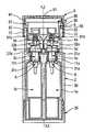
- FIGS. 4 a , 4 b , 4 c , 4 d , and 4 eare vertical-section views through the dispenser in FIGS. 1 to 3 in different dose-variation configurations;
- FIG. 5is a perspective view showing the inside of the rotary ring.
- the fluid dispenseris a “duo-type” dispenser including two reservoirs 1 a and 1 b , and two dispenser members 3 a and 3 b .
- the dispenser membersare pumps, but it is also possible to use valves.
- the present inventionis thus applied to a duo dispenser, but it can also be applied to a more conventional dispenser including only one reservoir and a single dispenser member.
- it has been chosen to describe the invention in a duo dispensersince such a configuration brings additional advantages compared to a conventional dispenser with a single reservoir and a single dispenser member. In particular, it is possible to vary the strokes of the two rods differently.
- the dispensercomprises fourteen component elements, namely: two fluid reservoirs 1 a and 1 b ; a covering shell 2 made of two portions; two dispenser members 3 a and 3 b that are pumps in this embodiment; two connection sleeves 4 a and 4 b ; two flexible ducts 5 a and 5 b ; a dispenser endpiece 6 forming a dispenser orifice 60 ; a return spring 7 ; dose-variation means 8 that are in the form of a rotary ring; and a common pusher 9 on which the user can press so as to actuate the dispenser.
- the two reservoirs 1 a and 1 bare preferably made of plastics material and advantageously they present cross-sections that are half-moon shaped. Thus, disposed in adjacent manner, the two reservoirs are inscribed in a cylinder. Each reservoir includes an opening 11 a , 11 b that is defined by a neck. Instead of the half-moon reservoirs, it is possible to use other reservoirs having different shapes.
- the external covering shell 2defines a main cylinder 20 that is extended upwards by a turret 22 . Internally, the shell 2 forms two reception housings 21 a and 21 b for receiving the dispenser members, as described below. At its bottom end, the shell is provided with a bottom wall 25 that is screw fastenable in this embodiment.
- the reservoirs 1 a and 1 bare disposed inside the shell 2 with their respective openings 11 a and 11 b disposed in the proximity of the reception housings 21 a , 21 b , as can be seen in FIG. 4 a .
- the shell 2is preferably made of plastics material, as is the bottom 25 . However, other materials can be used.
- the dispenser members 3 a and 3 bare pumps, each comprising a pump body 31 a , 31 b inside which an actuator rod 32 a , 32 b is axially movable down and up along axes X that are parallel in this embodiment.
- the actuator rods 32 a , 32 bare urged into their rest position by respective springs housed inside the body 31 a , 31 b . In their rest position, the rods 32 a , 32 b are extended to their maximum outside their respective body. By exerting axial pressure on the rods, said rods can be moved against internal springs (not shown) to an extreme low position. Thus, each actuator rod can be moved over a determined stroke between a high rest position and a low depressed position.
- Pumps 3 a and 3 bare received in stationary manner in the reception housings 21 a , 21 b formed by the shell 2 .
- Fasteningcan advantageously be achieved by snap-fastening the body 31 a , 31 b inside the housings 21 a , 21 b . Consequently, the bodies of the pumps are mounted in stationary manner relative to the reservoirs 1 a , 1 b and relative to the shell 2 .
- the rods 32 a , 32 bare axially movable along the respective axes X.
- each actuator rodis covered by a connection sleeve 4 a , 4 b that is engaged in leaktight manner on the free end of the rod.
- the connection sleeves 4 a , 4 bform an angle relative to the axes X.
- Each sleeveis connected to a flexible connection hose 21 a , 21 b that is capable of deforming when the respective rod is moved axially.
- the two flexible hosesare connected to a dispenser endpiece 6 that is mounted in stationary manner on the shell 2 , as can be seen in FIGS. 1 , 2 a , 2 b , and 3 .
- connection sleeves 4 a , 4 bare axially movable, whereas the dispenser endpiece 6 is stationary.
- the flexible connection hoses 21 a , 21 bmake it possible to connect the sleeves in fluid-flow manner to the endpiece while enabling the actuator rods to be moved axially.
- the sleeves 4 a , 4 b , the flexible hoses 21 a , 21 b , and the dispenser endpiece 6are made from separate parts in this embodiment. However, it is possible to make all of the parts as a single piece by molding the flexible hoses 21 a , 21 b onto the sleeves and the dispenser endpiece. Dual injection molding with different materials is advantageous, since the sleeves and the endpiece need to be substantially rigid, whereas the hoses need to present good flexibility.
- the dispenseris also provided with variation means 8 making it possible to vary the stroke of the actuator rods in such a manner as to dispense varying doses of fluid.
- the variation meansare in the form of a rotary ring 8 that is adapted to turn about an axis Z that advantageously extends parallel to the axes X.
- the axis Zpreferably extends mid-way between the axes X and in the same plane. In other words, the axis Z passes between the two actuator rods 32 a , 32 b .
- the ring 8includes a bottom bushing 82 that is engaged inside the turret 22 formed by the shell 2 . However, the ring 8 is free to turn inside the turret 22 about the axis Z.
- the ringforms a shoulder 83 that serves as anti-turning means by coming to bear against the top end of the turret 22 when the dispenser is in its rest position, as shown in FIG. 4 a .
- the ringforms a crown 84 that is provided with an actuator member 89 that, in this embodiment, is in the form of a small button that can be held by means of one or two fingers.
- the ring 8forms an annular track 81 that is visible in FIG. 5 .
- the track 81defines two bearing paths 81 a and 81 b for coming into contact with the actuator rods 32 a , 32 b , or more precisely with the connection sleeves 4 a , 4 b mounted on the ends of the rods.
- the bearing paths 81 a , 81 bdefine bearing zones that are situated at different axial heights. In order to bring the zones immediately above the actuator rods axially, it suffices to turn the ring 8 about the axis Z. In the embodiment shown in the figures, the paths define bearing zones in the form of sloping ramps and horizontal steps. This is visible in FIG. 5 . As a result, by turning the ring 8 , the distances separating the bearing paths from the connection sleeves vary.
- FIGS. 4 a and 4 eThis can be seen by comparing FIGS. 4 a and 4 e .
- the two paths 81 a and 81 bdefine two horizontal plane steps that are situated at the same axial level. The paths are practically in contact with the sleeves 4 a , 4 b .
- the ring 8In FIG. 4 b , the ring 8 has been turned a little, through approximately 25°, by manipulating the button 89 .
- the shoulder 83is no longer situated above the end of the turret 22 , but the bearing paths 81 a and 81 b remain at the same axial level as in FIG. 4 a .
- FIG. 4 aOn continuing to turn, as shown in FIG.
- the bearing path 81 bmoves away from the sleeve 4 b , whereas the bearing path 81 a remains at the same level as in FIGS. 4 a and 4 b .
- the bearing path 81 bforms a vertical riser 86 , visible in FIG. 5 . Consequently, at least one point along the bearing path is a combination of a sloping ramp, a horizontal flat, and a vertical riser.
- the two bearing pathsare situated once again at the same axial height, but at a distance from the connection sleeve that is greater than the distance in FIGS.
- the pusher 9includes a bearing surface 91 on which the user can press by means of one or more fingers, so as to move the pusher axially down and up along an axis Y that coincides with the axis Z of the ring 8 in this embodiment.
- the pusher 9also includes a substantially-cylindrical peripheral skirt 92 that is provided internally with axial grooves 93 that are engaged with corresponding splines formed on the turret 22 .
- the skirt 92 of the pusherforms an elongate window 98 that extends over nearly 150° in this embodiment. The window is clearly visible in FIGS.
- the actuator member 89 that is secured to the ringextends through the window 98 and can be moved along the window in such a manner as to turn the ring 8 inside the pusher 9 that is itself prevented from turning.
- the crown 84 of the ring 8is engaged inside the skirt 93 of the pusher, without said crown being prevented from turning.
- the actuator member 89is connected to the crown 84 .
- the bearing zone of the path 81 bmoves axially upwards so that it is at a maximum distance from the sleeve 4 b .
- the bearing zone of the path 81 aremains at the same axial height as for positions a and b.
- the path 81 acomes into contact with the sleeve 4 a immediately, and depresses the rod 32 a .
- the path 81 bdoes not come into contact with the sleeve 4 b , or else only comes into contact at the very end of the stroke. Consequently, the pump 3 a dispenses a complete dose, whereas the pump 3 b dispenses nothing at all.
- the usercollects a quantity of fluid that corresponds to 100% of a dose from the pump 3 a , and to 0% of a dose from the pump 3 b .
- position d in FIG. 3is reached, corresponding to FIG. 4 d .
- the bearing zones of the paths 81 a , 81 bare disposed once again at the same axial height, but at a distance from their sleeves that is situated mid-way between the positions in FIG. 4 c .
- the bearing pathsfirstly start to move closer to their corresponding sleeves.
- the bearing pathsthus come into abutment against their respective sleeves, and move the actuator rods over an incomplete stroke.
- the pumps 3 a and 3 bdispense incomplete doses, e.g. corresponding to half a dose.
- the usercollects a quantity of fluid that corresponds to 50% of a complete dose from the pump 3 a , and to 50% of a complete dose from the pump 3 b .
- position e in FIG. 3is reached, corresponding to FIG. 4 e .
- the path 81 bis in the direct proximity of the sleeve 4 b , whereas the path 81 a is at a maximum distance from the sleeve 4 d .
- the pump 3 adispenses nothing at all, whereas the pump 3 b dispenses a complete dose.
- the userthus collects a quantity of fluid that corresponds to 100% of the complete dose from the pump 3 b , and to 0% of the complete dose from the pump 3 a.
- the ring 8fulfils a function of transmitting force between the pusher 9 and the actuator rods. This force-transmission part is used to come into contact with the actuator rods, or more precisely with the connection sleeves mounted on the rods.
- the bearing paths 81 a and 81 bare preferably oriented with slopes that are generally opposite, so as to be able to vary the doses from the pumps in opposite manners, i.e. with one pump emitting 0% to 100% of its complete dose, for the other pump emitting from 100% to 0% of its complete dose.
- Thisis possible by means of the rotary ring 8 that includes two bearing paths that are disposed in a circular arc on a single track 81 , each path extending over substantially half of the track.
- the axis of rotation of the pathsis the axis Z that coincides with the axis Y of the pusher in this embodiment.
- FIG. 1shows a dispenser that incorporates stroke-variation means in the form of a rotary ring
- stroke-variation meansthat move in translation perpendicularly to the axes X of the actuator rods.
- a sliderdefining two bearing paths disposed side by side and movable perpendicularly to the axes X, so as to bring axially-offset bearing zones of the paths immediately above the actuator rods of the pumps.
- the bearing pathsare rectilinear and advantageously disposed in parallel manner. It is also possible to have the two paths in a single line, one behind the other.
Landscapes
- Chemical & Material Sciences (AREA)
- Dispersion Chemistry (AREA)
- Engineering & Computer Science (AREA)
- Mechanical Engineering (AREA)
- Containers And Packaging Bodies Having A Special Means To Remove Contents (AREA)
- Coating Apparatus (AREA)
- Reciprocating Pumps (AREA)
Abstract
Description
Claims (13)
Applications Claiming Priority (3)
| Application Number | Priority Date | Filing Date | Title |
|---|---|---|---|
| FR0655596 | 2006-12-18 | ||
| FR0655596AFR2909982B1 (en) | 2006-12-18 | 2006-12-18 | FLUID PRODUCT DISPENSER |
| PCT/FR2007/052504WO2008078045A2 (en) | 2006-12-18 | 2007-12-13 | Fluid product dispenser |
Publications (2)
| Publication Number | Publication Date |
|---|---|
| US20100044394A1 US20100044394A1 (en) | 2010-02-25 |
| US8418887B2true US8418887B2 (en) | 2013-04-16 |
Family
ID=38268709
Family Applications (1)
| Application Number | Title | Priority Date | Filing Date |
|---|---|---|---|
| US12/519,471Expired - Fee RelatedUS8418887B2 (en) | 2006-12-18 | 2007-12-13 | Fluid product dispenser |
Country Status (6)
| Country | Link |
|---|---|
| US (1) | US8418887B2 (en) |
| EP (1) | EP2102077B1 (en) |
| DE (1) | DE602007012472D1 (en) |
| ES (1) | ES2359129T3 (en) |
| FR (1) | FR2909982B1 (en) |
| WO (1) | WO2008078045A2 (en) |
Cited By (10)
| Publication number | Priority date | Publication date | Assignee | Title |
|---|---|---|---|---|
| US20120298694A1 (en)* | 2009-10-23 | 2012-11-29 | Werner Holzmann | Metering dispenser |
| USD730077S1 (en) | 2013-11-20 | 2015-05-26 | Nse Products, Inc. | Fluid dispenser |
| USD731203S1 (en) | 2013-11-20 | 2015-06-09 | Nse Products, Inc. | Fluid cartridge |
| USD731204S1 (en) | 2013-11-20 | 2015-06-09 | Nse Products, Inc. | Fluid cartridge |
| USD733455S1 (en) | 2013-11-20 | 2015-07-07 | Nse Products, Inc. | Fluid cartridge assembly |
| US10022741B2 (en) | 2014-08-22 | 2018-07-17 | Nse Products, Inc. | Selectively actuated fluid dispenser |
| US10307779B2 (en) | 2015-05-01 | 2019-06-04 | St&T Packaging Pte. Ltd. | Dual-chambered bottles for storing and dispensing of fluid and semi-fluid materials |
| US20190255547A1 (en)* | 2016-07-18 | 2019-08-22 | Rpc Bramlage Gmbh | Dispenser for liquid to pasty compositions |
| US11040364B2 (en)* | 2017-06-30 | 2021-06-22 | Aptar France Sas | Dual dispenser |
| US11484899B2 (en) | 2007-06-08 | 2022-11-01 | Diversey, Inc. | Fluid dispensing apparatus and method |
Families Citing this family (23)
| Publication number | Priority date | Publication date | Assignee | Title |
|---|---|---|---|---|
| NL2001675C2 (en)* | 2008-04-29 | 2009-10-30 | Medner Holding B V | Device for containing and metered delivery of at least one fluid. |
| US20240226935A9 (en)* | 2009-02-19 | 2024-07-11 | Bkb Holdings Llc | Multi-chamber fluid dispenser |
| USD636683S1 (en)* | 2010-05-27 | 2011-04-26 | The Gillette Company | Container |
| US8800818B2 (en)* | 2010-08-04 | 2014-08-12 | Evan Greenberg | Multi-chamber dispenser |
| WO2012032010A1 (en)* | 2010-09-06 | 2012-03-15 | Chiesi Farmaceutici S.P.A. | Metered-dose inhaler and method of using the same |
| USD728376S1 (en) | 2011-05-19 | 2015-05-05 | The Gillette Company | Container |
| DE202012004644U1 (en)* | 2012-05-11 | 2013-05-13 | Gerhard Brugger | Spray dispenser for several components |
| EP2735373A1 (en)* | 2012-10-30 | 2014-05-28 | Spirig Pharma AG | Dispenser device |
| CN104883984A (en)* | 2012-11-05 | 2015-09-02 | 史密夫和内修公司 | Assemblies and methods for fluid delivery |
| KR200476949Y1 (en)* | 2013-08-22 | 2015-04-20 | 펌텍코리아 (주) | A cosmetic container for sotoraging and discharging two contents |
| US9565978B2 (en)* | 2014-04-07 | 2017-02-14 | Dominick Hall | Multiple dispensing assembly |
| DE102014213469A1 (en)* | 2014-07-10 | 2016-01-14 | Aptar Radolfzell Gmbh | Discharge device with intermediate piece |
| USD887279S1 (en)* | 2015-06-05 | 2020-06-16 | Natura Cosméticos S.A. | Flask with cap |
| CN107089437A (en)* | 2016-04-16 | 2017-08-25 | 宁波市鄞州乐可机电科技有限公司 | A kind of cleaning solution bottle of push type |
| TWI730981B (en)* | 2016-08-24 | 2021-06-21 | 侯欣妤 | Structure of liquid container |
| US10584023B2 (en)* | 2018-06-29 | 2020-03-10 | Town & Country Linen Corp. | Multi reservoir dispenser |
| TWI689453B (en)* | 2019-08-01 | 2020-04-01 | 元盛生醫電子股份有限公司 | Distribution device |
| US11226224B2 (en)* | 2019-12-27 | 2022-01-18 | L'oreal | Dual dispensing pack |
| KR102383635B1 (en)* | 2020-08-24 | 2022-04-13 | 주식회사 삼화 | Cosmetic container |
| CN114615911A (en)* | 2020-10-05 | 2022-06-10 | 阿波罗工业株式会社 | Cosmetic container assembly capable of simultaneously discharging multiple contents |
| FR3133326A1 (en)* | 2022-03-08 | 2023-09-15 | Albea Services | Dispensing head for fluid product dispenser and associated dispenser |
| CN117326195A (en)* | 2022-06-23 | 2024-01-02 | 西尔格定量泵(无锡)有限公司 | Locking mechanism, dispensing pump assembly, container system and method of use |
| CN118458071A (en)* | 2024-05-30 | 2024-08-09 | 江苏新美星包装机械股份有限公司 | Anti-rotation device for dispenser |
Citations (13)
| Publication number | Priority date | Publication date | Assignee | Title |
|---|---|---|---|---|
| US4006841A (en)* | 1974-07-24 | 1977-02-08 | Girair Hagop Alticosalian | Perfume dispenser |
| FR2569581A1 (en) | 1984-08-28 | 1986-03-07 | Oreal | VAPORIZER WITH FLOW ADJUSTMENT DEVICE |
| FR2654016A1 (en) | 1989-11-06 | 1991-05-10 | Step Soc Tech Pulverisation | METERING MIXER PUSH BUTTON. |
| FR2658486A1 (en) | 1990-02-22 | 1991-08-23 | Valois | Adjustable travel push-button for manual fluid dispensing pump |
| US5363992A (en)* | 1992-12-31 | 1994-11-15 | Philip Meshberg | Variable spray and dosage pump |
| US5411176A (en)* | 1992-10-22 | 1995-05-02 | Lir-France | Variable dosage distributor for fluid products |
| WO1997007383A1 (en) | 1995-08-18 | 1997-02-27 | Aptargroup, Inc. | Pump mounting systems for fixed or variable dose operation |
| US5833121A (en)* | 1995-08-10 | 1998-11-10 | L'oreal | Packaging and dispensing device |
| US5971230A (en) | 1996-04-04 | 1999-10-26 | Soft 99 Corporation | Spray quantity control nozzle for aerosol container |
| US5971210A (en)* | 1995-07-23 | 1999-10-26 | Brugger; Gerhard | Dispenser for a liquid medium consisting of two components |
| US6464107B1 (en)* | 1998-08-14 | 2002-10-15 | Anton Brugger | Dosage dispenser |
| US20040251274A1 (en)* | 2002-12-20 | 2004-12-16 | L'oreal | Dispenser device including means that enable two substances to be dispensed in varying proportions |
| US6945430B2 (en)* | 2000-09-08 | 2005-09-20 | Rexam Dispensing Systems | Device for selectively dispensing two products |
- 2006
- 2006-12-18FRFR0655596Apatent/FR2909982B1/ennot_activeExpired - Fee Related
- 2007
- 2007-12-13WOPCT/FR2007/052504patent/WO2008078045A2/enactiveApplication Filing
- 2007-12-13USUS12/519,471patent/US8418887B2/ennot_activeExpired - Fee Related
- 2007-12-13DEDE602007012472Tpatent/DE602007012472D1/enactiveActive
- 2007-12-13EPEP07870393Apatent/EP2102077B1/enactiveActive
- 2007-12-13ESES07870393Tpatent/ES2359129T3/enactiveActive
Patent Citations (14)
| Publication number | Priority date | Publication date | Assignee | Title |
|---|---|---|---|---|
| US4006841A (en)* | 1974-07-24 | 1977-02-08 | Girair Hagop Alticosalian | Perfume dispenser |
| FR2569581A1 (en) | 1984-08-28 | 1986-03-07 | Oreal | VAPORIZER WITH FLOW ADJUSTMENT DEVICE |
| FR2654016A1 (en) | 1989-11-06 | 1991-05-10 | Step Soc Tech Pulverisation | METERING MIXER PUSH BUTTON. |
| FR2658486A1 (en) | 1990-02-22 | 1991-08-23 | Valois | Adjustable travel push-button for manual fluid dispensing pump |
| US5411176A (en)* | 1992-10-22 | 1995-05-02 | Lir-France | Variable dosage distributor for fluid products |
| US5363992A (en)* | 1992-12-31 | 1994-11-15 | Philip Meshberg | Variable spray and dosage pump |
| US5971210A (en)* | 1995-07-23 | 1999-10-26 | Brugger; Gerhard | Dispenser for a liquid medium consisting of two components |
| US5833121A (en)* | 1995-08-10 | 1998-11-10 | L'oreal | Packaging and dispensing device |
| WO1997007383A1 (en) | 1995-08-18 | 1997-02-27 | Aptargroup, Inc. | Pump mounting systems for fixed or variable dose operation |
| US5971230A (en) | 1996-04-04 | 1999-10-26 | Soft 99 Corporation | Spray quantity control nozzle for aerosol container |
| US6464107B1 (en)* | 1998-08-14 | 2002-10-15 | Anton Brugger | Dosage dispenser |
| US6945430B2 (en)* | 2000-09-08 | 2005-09-20 | Rexam Dispensing Systems | Device for selectively dispensing two products |
| US20040251274A1 (en)* | 2002-12-20 | 2004-12-16 | L'oreal | Dispenser device including means that enable two substances to be dispensed in varying proportions |
| US7222752B2 (en)* | 2002-12-20 | 2007-05-29 | L'oreal | Dispenser device including means that enable two substances to be dispensed in varying proportions |
Cited By (12)
| Publication number | Priority date | Publication date | Assignee | Title |
|---|---|---|---|---|
| US11484899B2 (en) | 2007-06-08 | 2022-11-01 | Diversey, Inc. | Fluid dispensing apparatus and method |
| US20120298694A1 (en)* | 2009-10-23 | 2012-11-29 | Werner Holzmann | Metering dispenser |
| US9346069B2 (en)* | 2009-10-23 | 2016-05-24 | Werner Holzmann | Metering dispenser |
| USD730077S1 (en) | 2013-11-20 | 2015-05-26 | Nse Products, Inc. | Fluid dispenser |
| USD731203S1 (en) | 2013-11-20 | 2015-06-09 | Nse Products, Inc. | Fluid cartridge |
| USD731204S1 (en) | 2013-11-20 | 2015-06-09 | Nse Products, Inc. | Fluid cartridge |
| USD733455S1 (en) | 2013-11-20 | 2015-07-07 | Nse Products, Inc. | Fluid cartridge assembly |
| US10022741B2 (en) | 2014-08-22 | 2018-07-17 | Nse Products, Inc. | Selectively actuated fluid dispenser |
| US10307779B2 (en) | 2015-05-01 | 2019-06-04 | St&T Packaging Pte. Ltd. | Dual-chambered bottles for storing and dispensing of fluid and semi-fluid materials |
| US20190255547A1 (en)* | 2016-07-18 | 2019-08-22 | Rpc Bramlage Gmbh | Dispenser for liquid to pasty compositions |
| US10618069B2 (en)* | 2016-07-18 | 2020-04-14 | Rpc Bramlage Gmbh | Dispenser for liquid to pasty compositions |
| US11040364B2 (en)* | 2017-06-30 | 2021-06-22 | Aptar France Sas | Dual dispenser |
Also Published As
| Publication number | Publication date |
|---|---|
| WO2008078045A3 (en) | 2008-09-18 |
| ES2359129T3 (en) | 2011-05-18 |
| EP2102077A2 (en) | 2009-09-23 |
| FR2909982A1 (en) | 2008-06-20 |
| DE602007012472D1 (en) | 2011-03-24 |
| WO2008078045A2 (en) | 2008-07-03 |
| US20100044394A1 (en) | 2010-02-25 |
| EP2102077B1 (en) | 2011-02-09 |
| FR2909982B1 (en) | 2011-03-18 |
Similar Documents
| Publication | Publication Date | Title |
|---|---|---|
| US8418887B2 (en) | Fluid product dispenser | |
| US7857174B2 (en) | Fluid dispenser | |
| US8490837B2 (en) | Fluid material dispensing head | |
| US8608031B2 (en) | Lockable dispensing head | |
| EP3509964B1 (en) | Pump dispenser with actuating collar | |
| EP1988798B1 (en) | Dispensers e.g. for cosmetics | |
| CN103517766B (en) | Side actuated fluid product dispensing device | |
| US20140020789A1 (en) | Dropper dispenser | |
| US8096450B2 (en) | Lateral actuation spray device | |
| US20120292344A1 (en) | Head for dispensing fluid material | |
| CZ291850B6 (en) | Locking-stressing-mechanism for a spring-actuated output drive device | |
| US7997451B2 (en) | Fluid product dispensing member and a dispenser provided therewith | |
| CN1471436A (en) | Multi-dose fluid product dispensing device | |
| CN103517857B (en) | Side actuated fluid product dispensing device | |
| US8857671B2 (en) | Device for distributing a fluid product | |
| US8016163B2 (en) | Fluid dispenser head | |
| CA2830775A1 (en) | Dispenser | |
| WO2005030401A1 (en) | A dispensing apparatus | |
| US7828177B2 (en) | Dispenser head | |
| CN110785240B (en) | Double distributor | |
| CN103502113B (en) | Side actuated fluid product dispensing device | |
| US7510100B2 (en) | Dose indicator for a fluid dispenser device | |
| US7708168B2 (en) | Fluid dispenser member | |
| US11318489B2 (en) | Fluid product dispenser | |
| US20030173377A1 (en) | Single-nozzle device for selectively dispensing two products |
Legal Events
| Date | Code | Title | Description |
|---|---|---|---|
| AS | Assignment | Owner name:VALOIS SAS,FRANCE Free format text:ASSIGNMENT OF ASSIGNORS INTEREST;ASSIGNORS:MILIAN, ALEX;POULIAUDE, FLORENT;REEL/FRAME:022832/0495 Effective date:20090610 Owner name:VALOIS SAS, FRANCE Free format text:ASSIGNMENT OF ASSIGNORS INTEREST;ASSIGNORS:MILIAN, ALEX;POULIAUDE, FLORENT;REEL/FRAME:022832/0495 Effective date:20090610 | |
| AS | Assignment | Owner name:APTAR FRANCE SAS, FRANCE Free format text:CHANGE OF NAME;ASSIGNOR:VALOIS;REEL/FRAME:028930/0943 Effective date:20120725 | |
| STCF | Information on status: patent grant | Free format text:PATENTED CASE | |
| FPAY | Fee payment | Year of fee payment:4 | |
| MAFP | Maintenance fee payment | Free format text:PAYMENT OF MAINTENANCE FEE, 8TH YEAR, LARGE ENTITY (ORIGINAL EVENT CODE: M1552); ENTITY STATUS OF PATENT OWNER: LARGE ENTITY Year of fee payment:8 | |
| FEPP | Fee payment procedure | Free format text:MAINTENANCE FEE REMINDER MAILED (ORIGINAL EVENT CODE: REM.); ENTITY STATUS OF PATENT OWNER: LARGE ENTITY | |
| LAPS | Lapse for failure to pay maintenance fees | Free format text:PATENT EXPIRED FOR FAILURE TO PAY MAINTENANCE FEES (ORIGINAL EVENT CODE: EXP.); ENTITY STATUS OF PATENT OWNER: LARGE ENTITY | |
| STCH | Information on status: patent discontinuation | Free format text:PATENT EXPIRED DUE TO NONPAYMENT OF MAINTENANCE FEES UNDER 37 CFR 1.362 | |
| FP | Lapsed due to failure to pay maintenance fee | Effective date:20250416 |