US8418784B2 - Central cutting region of a drilling head assembly - Google Patents
Central cutting region of a drilling head assemblyDownload PDFInfo
- Publication number
- US8418784B2 US8418784B2US12/777,429US77742910AUS8418784B2US 8418784 B2US8418784 B2US 8418784B2US 77742910 AUS77742910 AUS 77742910AUS 8418784 B2US8418784 B2US 8418784B2
- Authority
- US
- United States
- Prior art keywords
- assembly
- blade
- degradation
- degradation element
- cutting region
- Prior art date
- Legal status (The legal status is an assumption and is not a legal conclusion. Google has not performed a legal analysis and makes no representation as to the accuracy of the status listed.)
- Expired - Fee Related, expires
Links
Images


Classifications
- E—FIXED CONSTRUCTIONS
- E21—EARTH OR ROCK DRILLING; MINING
- E21B—EARTH OR ROCK DRILLING; OBTAINING OIL, GAS, WATER, SOLUBLE OR MELTABLE MATERIALS OR A SLURRY OF MINERALS FROM WELLS
- E21B10/00—Drill bits
- E21B10/44—Bits with helical conveying portion, e.g. screw type bits; Augers with leading portion or with detachable parts
Definitions
- the present inventionrelates to a drilling assembly, and more particularly to the central region of a drilling head assembly for boring into formations.
- U.S. Pat. No. 5,366,031 to Richardswhich is herein incorporated by reference for all that it contains, discloses an auger with a boring head having an arrangement for cutting relatively hard earth formations such as rock.
- First and second groups of drill bitsare mounted to the boring head such that when the head is rotated, each bit in those groups cuts a different path at a different height to provide more than 100% coverage of the work surface being cut, while stabilizing the auger by distributing the down force of the auger over the entire bit rotation.
- the drill bitsalso are oriented to ensure bit rotation at relatively large attack angles (the angle the bit forms with the work surface there beneath) of about 50° to 60° to enhance auger penetration rates without detracting from the bit sharpening effect that results from proper bit rotation.
- U.S. Pat. No. 3,821,993 to Kniffwhich is herein incorporated by reference for all that it contains, discloses an auger arrangement for boring holes in earth formations in which the auger comprises a body with a central cutter arrangement including a pilot cutter on the axis and with laterally extending wing portions on the auger, on each of which is pivotally mounted a wing cutter arranged to swing outwardly when the auger rotates in cutting direction and to swing inwardly when the auger is not rotating or when it is rotating in the reverse direction so that the auger can readily be withdrawn from a hole bored thereby.
- U.S. Pat. No. 3,763,942 to Levittwhich is herein incorporated by reference for all that it contains, discloses an auger or boring head, especially for horizontal rock and earth drilling having a circular ring of circumferentially spaced tool bits or teeth, a plurality of spokes or fins with leading ends carrying tool bits or cutting teeth in convex curved or arcuate contours from a central cutting point forwardly of the ring to the periphery of the ring.
- the cutting teeth on the ringproject radially outward from the periphery thereof and are tilted forwardly in the direction of rotation of the auger head.
- the cutting teeth on the spokes or finsproject forwardly, are tilted toward the direction of rotation of the heard and are also tilted backwardly to present the tip end of each tooth in a straight forward direction to the surface while it is cutting.
- the teethare staggered so that successive teeth will not have the same cutting track.
- a head or socketis provided in the center of the auger head for connection to a drill rod or stem. Large open areas are provided through the ring between the spokes or fins, and the earth or rock cut by the head is free to flow through these spaces to a spiral conveyor which preferably has it leading edge behind one of the spokes or fins.
- a drilling assemblycomprises a head located on a rotational axis of the assembly and comprises at least one head element. At least one blade extends distally from the head. A plurality of blade degradation elements are rotationally supported on the blade. Each degradation element comprises an attack angle that affects the penetration rate of each degradation element and a laterally offset angle that primarily affects the rotational rate of each degradation element within their holders fixed to the blade.
- the drilling assemblycomprises a central cutting region on each blade. The blade degradation elements within the central cutting region form an angle between 15 and 20 degrees with the rotational axis of the drilling assembly.
- the central cutting regionmay be defined within a 13 inch radius from the rotational axis of the drilling assembly.
- the central cutting regionmay also be defined within a six inch radius from the rotational axis of the drilling assembly.
- the attack anglemay be between 16 and 18 degrees.
- the blademay comprise at least one degradation element.
- the plurality of blade degradation elementsmay comprise a wear resistant tip comprising a pointed sintered polycrystalline diamond compact supported on a cemented metal carbide support.
- the supportmay be bonded to a cemented metal carbide bolster at a forward diameter, which comprises a cross-sectional thickness less than or substantially equal to a largest diameter of the bolster.
- the supportmay be segmented. At least one segment of the support may be press fitted into a cavity of a body of the degradation element.
- the pointed diamond compactmay comprise a greater axial thickness than an immediately adjacent segment of the support.
- the pointed diamond compactmay comprise a greater axial thickness than the support.
- the pointed diamond compactmay comprise a curvature formed in a plane substantially parallel with a central axis of the tip. The curvature may be between 0.050 and 0.110 inch radius of curvature.
- the assemblymay be an auger assembly.
- the assemblymay be a coring bucket assembly.
- FIG. 1is a perspective diagram of an embodiment of a drilling assembly.
- FIG. 2is a perspective diagram of an embodiment of a drilling head assembly.
- FIG. 3is a perspective diagram of another embodiment of a drilling head assembly.
- FIG. 4is a perspective diagram of an embodiment of a plurality of blade degradation elements.
- FIG. 5is an exploded view of a diagram of an embodiment of a blade degradation element.
- FIG. 6is a cross-sectional diagram of an embodiment of a blade degradation element.
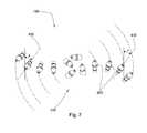
- FIG. 7is an orthogonal diagram of an embodiment of a drilling head assembly.
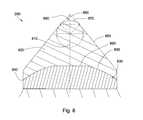
- FIG. 8is a cross-sectional diagram of another embodiment of a tip.
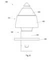
- FIG. 9is an orthogonal diagram of another embodiment of a blade degradation element.
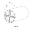
- FIG. 10is a perspective diagram of an embodiment of a drilling assembly.
- FIG. 1is a perspective diagram of an embodiment of a drilling assembly constructed in accordance with the present invention.
- the drilling assemblyis a auger assembly.
- the auger assembly 100comprises an auger shaft 101 , first blade 105 , second blade 110 and a central cutting region 120 .
- the first blade 101 and the second blade 110are arranged in a helical position around the shaft 101 to convey debris to the surface of the area being excavated.
- the central cutting region 120includes a boring head 130 , first and second blade assemblies and a main head 150 .
- the boring head 130is secured to one end of the auger shaft 101 , and an end portion of the first and second blades 105 , 110 .
- the main head 150is releasably secured to the boring head 130 to facilitate replacement of the main head 150 .
- the shaft 101 , boring head 130 , and the main head 150collectively share a common rotational axis 160 .
- Both blades 105 , 110may comprise a plurality of blade degradation elements 200 attached to an edge of the blades 105 , 110 .
- the plurality of blade degradation elements 200may comprise an attack angle ( ⁇ ) of 15 to 20 degrees.
- the attack angleis formed between a central axis of the blade degradation element and the rotational axis of the drilling head assembly.
- a 15 to 20 degree angle for blade degradation elements within the central cutting regionis believed to have an optimal performance when the blade degradation cutting elements are enhanced with tips of comprising sintered polycrystalline diamond.
- the central cutting regionis less than 26 inches in diameter.
- the diametermay be closer to 12 inches.
- the blade degradation elementsmay form an attack angle of 16 to 18 degrees.
- the attack angleis closer to 17 degrees.
- the attack angledetermine penetration rate of the drilling assembly. It is believed that the blade degradation elements or the gauge degradation elements that are not within the central cutting region should have attack angles greater than 20 degrees.
- FIG. 3discloses a drilling head assembly with an overall diameter that is just over the central cutting region's diameter.
- the majority of the blade degradation elementswill form an angle of 15 to 20 degrees.
- only the gauge degradation elementsform an angle greater than 20 degrees.
- FIG. 4discloses an embodiment of blade degradation elements 200 attached to either first blade 105 or second blade 110 .
- the attack angle ( ⁇ ) of each of the degradation elements 200may be between 15 and 20 degrees, which allows greater penetration rates, and thus faster boring rates.
- the attack angle ( ⁇ )is defined as the angle formed between the vertical axis 401 of a formation 400 and a rotational axis 410 of the degradation element 200 .
- FIG. 5discloses an exploded view of an embodiment of a blade degradation element 200 .
- the degradation element 200may comprise a wear resistant tip 260 comprising a pointed sintered polycrystalline diamond compact 420 supported on a cemented metal carbide support 430 .
- the carbide support 430may be segmented. At least one segment of the support 430 may be press fit into a cavity 450 of a body of the degradation element 200 .
- the degradation element 200may comprise a braze joint.
- the support 430may be bonded to a cemented metal carbide bolster 460 at a forward diameter, which comprises a cross-sectional thickness less than or substantially equal to a largest diameter of the bolster 460 .
- the bolster 460may comprise cemented metal carbide, a steel matrix material, or other material and may be press fit or brazed to a drill bit body.
- the pointed diamond compact 420may comprise a greater axial thickness than an immediately adjacent segment of the support 430 . Such composition of the tip 260 of the degradation element 200 may increase the longevity of the degradation elements 200 . In some embodiments, the pointed diamond compact 260 may comprise a greater axial thickness than the support 430 .
- the degradation element 200may be attached to a holder 650 mounted on the blades 105 , 110 .
- Each degradation element 200induces a load into the formation 400 , which in turn imposes a reaction force on the pick.
- the reaction forcesmay depend on WOB, rpm, formation type, torque, or combinations thereof.
- a balance between penetration rate and lifespan of the blade degradation element 200may be obtained when a resultant force vector aligns with an axis 410 of the degradation element 200 .
- the fracturesmay propagate in the formation 400 , resulting in a removal of chips 600 of formation 400 .
- the degradation elements 200may rotate while following a helical path. Each degradation element 200 may follow a separate helical path as the auger assembly 100 drills deeper into a formation. Each degradation element 200 may comprise a laterally offset angle ( ⁇ ), which imposes a lateral force on the pick adapted to cause the pick to rotate. If the rotational axis 410 of the degradation element 200 is tangent to the helical cutting path, the offset angle ( ⁇ ) is generally zero. The degradation elements 200 may continue to rotate in their holders (not shown) for a wide range of offset angle ( ⁇ ).
- the degradation element 200may comprise a sintered polycrystalline diamond compact 420 bonded to a cemented metal carbide substrate 830 at a non-planar interface 840 .
- the degradation element 200may comprise a substantially pointed geometry 850 and an apex 860 .
- the apex 860may comprise a curvature 870 formed in a plane substantially parallel with a central axis of the tip 410 .
- the curvature 870may be between 0.050 and 0.110 inch radius of curvature.
- the curvature 870may comprise a variable radius of curvature, a portion of a parabola, a portion of a hyperbola, a portion of a catenary, or a parametric spline.
- An included angle 880is formed by the walls of the pointed geometry 850 . In some embodiments, the included angle 880 may be between 75 degrees and 90 degrees.
- Non-planar interface 840may comprise an elevated flatted region 890 that connects to a cylindrical portion of the substrate 830 by a tapered section 895 .
- the diamond compact 420may comprise a volume with less than 5 percent catalyst metal concentration, while 95 percent of the interstices in the sintered polycrystalline diamond comprise a catalyst.
- FIG. 9discloses an embodiment of a blade degradation element 990 which may be used in machines in mining, asphalt milling, or trenching industries.
- the element 990may be used in auger assembly 100 .
- the element 990may comprise a shank 900 and a body 910 , the body 910 being divided into first and second segments 920 & 930 .
- the shank 900may be adapted to be attached to a driving mechanism.
- a protective spring sleeve 940may be disposed around the shank 900 both for protection and to allow the degradation element 990 to be press fit into the holder (not shown) while still being able to rotate.
- a washer 950may be disposed around the shank 900 such that when the element 990 is inserted into the holder, the washer 950 protects an upper surface of the holder and also facilitates rotation of the element 990 .
- the washer 950 and sleeve 940may be advantageous since they may protect the holder which may be costly to replace.
- the wear resistant tips 260may comprise a pointed sintered polycrystalline diamond compact supported on a cemented metal carbide support.
- Chemical vapor deposition (CVD) techniquemay be used and may provide precise shapes, but it may not provide as strong bonding between diamond crystals.
- sintered diamondis used, which is subjected to high temperature and high pressure resulting in strong bonds between diamond crystals. Natural diamonds may also be used.
- FIG. 10discloses that the present invention may be incorporated into a coring bucket assembly 1000 as well as other drilling assemblies.
- the assembly 1000may comprise a plurality of degradation elements 200 at one end disposed in a particular order as well as particular orientation as shown in the figure.
- the assembly 1000may be used to drill through clay, soft soil, hard rock, or combinations thereof.
- the picksare rigidly fixed within the holders such that there is no rotation.
- the picksare allowed to rotate, but the assembly comprises a mechanism that restricts free rotation causing the picks to rotate slower. This may be advantageous by reducing the wear between the shank of the pick and the inner bore of the holder.
Landscapes
- Engineering & Computer Science (AREA)
- Life Sciences & Earth Sciences (AREA)
- Geology (AREA)
- Mining & Mineral Resources (AREA)
- Mechanical Engineering (AREA)
- Physics & Mathematics (AREA)
- Environmental & Geological Engineering (AREA)
- Fluid Mechanics (AREA)
- General Life Sciences & Earth Sciences (AREA)
- Geochemistry & Mineralogy (AREA)
- Earth Drilling (AREA)
Abstract
Description
Claims (14)
Priority Applications (1)
| Application Number | Priority Date | Filing Date | Title |
|---|---|---|---|
| US12/777,429US8418784B2 (en) | 2010-05-11 | 2010-05-11 | Central cutting region of a drilling head assembly |
Applications Claiming Priority (1)
| Application Number | Priority Date | Filing Date | Title |
|---|---|---|---|
| US12/777,429US8418784B2 (en) | 2010-05-11 | 2010-05-11 | Central cutting region of a drilling head assembly |
Publications (2)
| Publication Number | Publication Date |
|---|---|
| US20110278072A1 US20110278072A1 (en) | 2011-11-17 |
| US8418784B2true US8418784B2 (en) | 2013-04-16 |
Family
ID=44910763
Family Applications (1)
| Application Number | Title | Priority Date | Filing Date |
|---|---|---|---|
| US12/777,429Expired - Fee RelatedUS8418784B2 (en) | 2010-05-11 | 2010-05-11 | Central cutting region of a drilling head assembly |
Country Status (1)
| Country | Link |
|---|---|
| US (1) | US8418784B2 (en) |
Cited By (1)
| Publication number | Priority date | Publication date | Assignee | Title |
|---|---|---|---|---|
| US10344441B2 (en) | 2015-06-01 | 2019-07-09 | West Virginia University | Fiber-reinforced polymer shell systems and methods for encapsulating piles with concrete columns extending below the earth's surface |
Families Citing this family (3)
| Publication number | Priority date | Publication date | Assignee | Title |
|---|---|---|---|---|
| JP5869348B2 (en)* | 2012-01-25 | 2016-02-24 | 株式会社技研製作所 | Auger head |
| CN103510850B (en)* | 2013-10-16 | 2017-04-05 | 武汉武船机电设备有限责任公司 | A kind of piling drilling rig |
| CN110513065B (en)* | 2019-09-30 | 2024-05-10 | 北京三一智造科技有限公司 | Spiral barrel drill |
Citations (147)
| Publication number | Priority date | Publication date | Assignee | Title |
|---|---|---|---|---|
| US465103A (en) | 1891-12-15 | Combined drill | ||
| US616118A (en) | 1898-12-20 | Ernest kuhne | ||
| US946060A (en) | 1908-10-10 | 1910-01-11 | David W Looker | Post-hole auger. |
| US1116154A (en) | 1913-03-26 | 1914-11-03 | William G Stowers | Post-hole digger. |
| US1183600A (en) | 1915-10-27 | 1916-05-16 | John W Stahl | Antirattler for automobile steering devices. |
| US1188560A (en) | 1915-07-08 | 1916-06-27 | Carleton Ruhe | Automatic stop mechanism. |
| US1360908A (en) | 1920-07-16 | 1920-11-30 | Everson August | Reamer |
| US1387733A (en) | 1921-02-15 | 1921-08-16 | Penelton G Midgett | Well-drilling bit |
| US1460671A (en) | 1920-06-17 | 1923-07-03 | Hebsacker Wilhelm | Excavating machine |
| US1544757A (en) | 1923-02-05 | 1925-07-07 | Hufford | Oil-well reamer |
| US1821474A (en) | 1927-12-05 | 1931-09-01 | Sullivan Machinery Co | Boring tool |
| US1879177A (en) | 1930-05-16 | 1932-09-27 | W J Newman Company | Drilling apparatus for large wells |
| US2054255A (en) | 1934-11-13 | 1936-09-15 | John H Howard | Well drilling tool |
| US2064255A (en) | 1936-06-19 | 1936-12-15 | Hughes Tool Co | Removable core breaker |
| US2169223A (en) | 1937-04-10 | 1939-08-15 | Carl C Christian | Drilling apparatus |
| US2218130A (en) | 1938-06-14 | 1940-10-15 | Shell Dev | Hydraulic disruption of solids |
| US2320136A (en) | 1940-09-30 | 1943-05-25 | Archer W Kammerer | Well drilling bit |
| US2466991A (en) | 1945-06-06 | 1949-04-12 | Archer W Kammerer | Rotary drill bit |
| US2540464A (en) | 1947-05-31 | 1951-02-06 | Reed Roller Bit Co | Pilot bit |
| US2544036A (en) | 1946-09-10 | 1951-03-06 | Edward M Mccann | Cotton chopper |
| US2755071A (en) | 1954-08-25 | 1956-07-17 | Rotary Oil Tool Company | Apparatus for enlarging well bores |
| US2776819A (en) | 1953-10-09 | 1957-01-08 | Philip B Brown | Rock drill bit |
| US2819043A (en) | 1955-06-13 | 1958-01-07 | Homer I Henderson | Combination drilling bit |
| US2838284A (en) | 1956-04-19 | 1958-06-10 | Christensen Diamond Prod Co | Rotary drill bit |
| US2894722A (en) | 1953-03-17 | 1959-07-14 | Ralph Q Buttolph | Method and apparatus for providing a well bore with a deflected extension |
| US2901223A (en) | 1955-11-30 | 1959-08-25 | Hughes Tool Co | Earth boring drill |
| US2963102A (en) | 1956-08-13 | 1960-12-06 | James E Smith | Hydraulic drill bit |
| US3135341A (en) | 1960-10-04 | 1964-06-02 | Christensen Diamond Prod Co | Diamond drill bits |
| US3294186A (en) | 1964-06-22 | 1966-12-27 | Tartan Ind Inc | Rock bits and methods of making the same |
| US3301339A (en) | 1964-06-19 | 1967-01-31 | Exxon Production Research Co | Drill bit with wear resistant material on blade |
| US3379264A (en) | 1964-11-05 | 1968-04-23 | Dravo Corp | Earth boring machine |
| US3429390A (en) | 1967-05-19 | 1969-02-25 | Supercussion Drills Inc | Earth-drilling bits |
| US3493165A (en) | 1966-11-18 | 1970-02-03 | Georg Schonfeld | Continuous tunnel borer |
| US3583504A (en) | 1969-02-24 | 1971-06-08 | Mission Mfg Co | Gauge cutting bit |
| US3720273A (en)* | 1971-03-03 | 1973-03-13 | Kennametal Inc | Mining tool |
| US3764493A (en) | 1972-08-31 | 1973-10-09 | Us Interior | Recovery of nickel and cobalt |
| US3763942A (en)* | 1972-02-25 | 1973-10-09 | Contracting & Material Co | Auger head |
| US3821993A (en) | 1971-09-07 | 1974-07-02 | Kennametal Inc | Auger arrangement |
| US3905432A (en)* | 1971-07-12 | 1975-09-16 | Hughes Tool Co | Auger with rotatable cutters |
| US3955635A (en) | 1975-02-03 | 1976-05-11 | Skidmore Sam C | Percussion drill bit |
| US3960223A (en) | 1974-03-26 | 1976-06-01 | Gebrueder Heller | Drill for rock |
| US4081042A (en) | 1976-07-08 | 1978-03-28 | Tri-State Oil Tool Industries, Inc. | Stabilizer and rotary expansible drill bit apparatus |
| US4096917A (en) | 1975-09-29 | 1978-06-27 | Harris Jesse W | Earth drilling knobby bit |
| US4106577A (en) | 1977-06-20 | 1978-08-15 | The Curators Of The University Of Missouri | Hydromechanical drilling device |
| US4109737A (en) | 1976-06-24 | 1978-08-29 | General Electric Company | Rotary drill bit |
| US4176723A (en) | 1977-11-11 | 1979-12-04 | DTL, Incorporated | Diamond drill bit |
| US4253533A (en) | 1979-11-05 | 1981-03-03 | Smith International, Inc. | Variable wear pad for crossflow drag bit |
| US4280573A (en) | 1979-06-13 | 1981-07-28 | Sudnishnikov Boris V | Rock-breaking tool for percussive-action machines |
| US4304312A (en) | 1980-01-11 | 1981-12-08 | Sandvik Aktiebolag | Percussion drill bit having centrally projecting insert |
| US4307786A (en) | 1978-07-27 | 1981-12-29 | Evans Robert F | Borehole angle control by gage corner removal effects from hydraulic fluid jet |
| US4397361A (en) | 1981-06-01 | 1983-08-09 | Dresser Industries, Inc. | Abradable cutter protection |
| US4416339A (en) | 1982-01-21 | 1983-11-22 | Baker Royce E | Bit guidance device and method |
| US4445580A (en) | 1979-06-19 | 1984-05-01 | Syndrill Carbide Diamond Company | Deep hole rock drill bit |
| US4448269A (en) | 1981-10-27 | 1984-05-15 | Hitachi Construction Machinery Co., Ltd. | Cutter head for pit-boring machine |
| US4499795A (en) | 1983-09-23 | 1985-02-19 | Strata Bit Corporation | Method of drill bit manufacture |
| US4531592A (en) | 1983-02-07 | 1985-07-30 | Asadollah Hayatdavoudi | Jet nozzle |
| US4535853A (en) | 1982-12-23 | 1985-08-20 | Charbonnages De France | Drill bit for jet assisted rotary drilling |
| US4538691A (en) | 1984-01-30 | 1985-09-03 | Strata Bit Corporation | Rotary drill bit |
| US4566545A (en) | 1983-09-29 | 1986-01-28 | Norton Christensen, Inc. | Coring device with an improved core sleeve and anti-gripping collar with a collective core catcher |
| US4574895A (en) | 1982-02-22 | 1986-03-11 | Hughes Tool Company - Usa | Solid head bit with tungsten carbide central core |
| US4640374A (en) | 1984-01-30 | 1987-02-03 | Strata Bit Corporation | Rotary drill bit |
| US4852672A (en) | 1988-08-15 | 1989-08-01 | Behrens Robert N | Drill apparatus having a primary drill and a pilot drill |
| US4889017A (en) | 1984-07-19 | 1989-12-26 | Reed Tool Co., Ltd. | Rotary drill bit for use in drilling holes in subsurface earth formations |
| US4962822A (en) | 1989-12-15 | 1990-10-16 | Numa Tool Company | Downhole drill bit and bit coupling |
| US4981184A (en) | 1988-11-21 | 1991-01-01 | Smith International, Inc. | Diamond drag bit for soft formations |
| US5009273A (en) | 1988-01-08 | 1991-04-23 | Foothills Diamond Coring (1980) Ltd. | Deflection apparatus |
| US5027914A (en) | 1990-06-04 | 1991-07-02 | Wilson Steve B | Pilot casing mill |
| US5038873A (en) | 1989-04-13 | 1991-08-13 | Baker Hughes Incorporated | Drilling tool with retractable pilot drilling unit |
| US5119892A (en) | 1989-11-25 | 1992-06-09 | Reed Tool Company Limited | Notary drill bits |
| US5141063A (en) | 1990-08-08 | 1992-08-25 | Quesenbury Jimmy B | Restriction enhancement drill |
| US5158147A (en)* | 1991-08-09 | 1992-10-27 | Mobile Drilling Company, Inc. | Auger cutter head |
| US5186268A (en) | 1991-10-31 | 1993-02-16 | Camco Drilling Group Ltd. | Rotary drill bits |
| US5222566A (en) | 1991-02-01 | 1993-06-29 | Camco Drilling Group Ltd. | Rotary drill bits and methods of designing such drill bits |
| US5255749A (en) | 1992-03-16 | 1993-10-26 | Steer-Rite, Ltd. | Steerable burrowing mole |
| US5265682A (en) | 1991-06-25 | 1993-11-30 | Camco Drilling Group Limited | Steerable rotary drilling systems |
| US5361859A (en) | 1993-02-12 | 1994-11-08 | Baker Hughes Incorporated | Expandable gage bit for drilling and method of drilling |
| US5366031A (en)* | 1993-05-03 | 1994-11-22 | Pengo Corporation | Auger head assembly and method of drilling hard earth formations |
| US5410303A (en) | 1991-05-15 | 1995-04-25 | Baroid Technology, Inc. | System for drilling deivated boreholes |
| US5417292A (en) | 1993-11-22 | 1995-05-23 | Polakoff; Paul | Large diameter rock drill |
| US5423389A (en) | 1994-03-25 | 1995-06-13 | Amoco Corporation | Curved drilling apparatus |
| US5507357A (en) | 1994-02-04 | 1996-04-16 | Foremost Industries, Inc. | Pilot bit for use in auger bit assembly |
| US5560440A (en) | 1993-02-12 | 1996-10-01 | Baker Hughes Incorporated | Bit for subterranean drilling fabricated from separately-formed major components |
| US5568838A (en) | 1994-09-23 | 1996-10-29 | Baker Hughes Incorporated | Bit-stabilized combination coring and drilling system |
| US5655614A (en) | 1994-12-20 | 1997-08-12 | Smith International, Inc. | Self-centering polycrystalline diamond cutting rock bit |
| US5678644A (en) | 1995-08-15 | 1997-10-21 | Diamond Products International, Inc. | Bi-center and bit method for enhancing stability |
| US5732784A (en) | 1996-07-25 | 1998-03-31 | Nelson; Jack R. | Cutting means for drag drill bits |
| US5794728A (en) | 1995-06-20 | 1998-08-18 | Sandvik Ab | Percussion rock drill bit |
| US5848657A (en) | 1996-12-27 | 1998-12-15 | General Electric Company | Polycrystalline diamond cutting element |
| US5896938A (en) | 1995-12-01 | 1999-04-27 | Tetra Corporation | Portable electrohydraulic mining drill |
| US5947215A (en) | 1997-11-06 | 1999-09-07 | Sandvik Ab | Diamond enhanced rock drill bit for percussive drilling |
| US5950743A (en) | 1997-02-05 | 1999-09-14 | Cox; David M. | Method for horizontal directional drilling of rock formations |
| US5957225A (en) | 1997-07-31 | 1999-09-28 | Bp Amoco Corporation | Drilling assembly and method of drilling for unstable and depleted formations |
| US5957223A (en) | 1997-03-05 | 1999-09-28 | Baker Hughes Incorporated | Bi-center drill bit with enhanced stabilizing features |
| US5967247A (en) | 1997-09-08 | 1999-10-19 | Baker Hughes Incorporated | Steerable rotary drag bit with longitudinally variable gage aggressiveness |
| US5979571A (en) | 1996-09-27 | 1999-11-09 | Baker Hughes Incorporated | Combination milling tool and drill bit |
| US5992548A (en) | 1995-08-15 | 1999-11-30 | Diamond Products International, Inc. | Bi-center bit with oppositely disposed cutting surfaces |
| US5992547A (en) | 1995-10-10 | 1999-11-30 | Camco International (Uk) Limited | Rotary drill bits |
| US6021859A (en) | 1993-12-09 | 2000-02-08 | Baker Hughes Incorporated | Stress related placement of engineered superabrasive cutting elements on rotary drag bits |
| US6039131A (en) | 1997-08-25 | 2000-03-21 | Smith International, Inc. | Directional drift and drill PDC drill bit |
| US6131675A (en) | 1998-09-08 | 2000-10-17 | Baker Hughes Incorporated | Combination mill and drill bit |
| US6150822A (en) | 1994-01-21 | 2000-11-21 | Atlantic Richfield Company | Sensor in bit for measuring formation properties while drilling |
| US6186251B1 (en) | 1998-07-27 | 2001-02-13 | Baker Hughes Incorporated | Method of altering a balance characteristic and moment configuration of a drill bit and drill bit |
| US6202761B1 (en) | 1998-04-30 | 2001-03-20 | Goldrus Producing Company | Directional drilling method and apparatus |
| US6213226B1 (en) | 1997-12-04 | 2001-04-10 | Halliburton Energy Services, Inc. | Directional drilling assembly and method |
| US6223824B1 (en) | 1996-06-17 | 2001-05-01 | Weatherford/Lamb, Inc. | Downhole apparatus |
| US20010004946A1 (en) | 1997-11-28 | 2001-06-28 | Kenneth M. Jensen | Enhanced non-planar drill insert |
| US6269893B1 (en) | 1999-06-30 | 2001-08-07 | Smith International, Inc. | Bi-centered drill bit having improved drilling stability mud hydraulics and resistance to cutter damage |
| US6296069B1 (en) | 1996-12-16 | 2001-10-02 | Dresser Industries, Inc. | Bladed drill bit with centrally distributed diamond cutters |
| US6332503B1 (en) | 1992-01-31 | 2001-12-25 | Baker Hughes Incorporated | Fixed cutter bit with chisel or vertical cutting elements |
| US6340064B2 (en) | 1999-02-03 | 2002-01-22 | Diamond Products International, Inc. | Bi-center bit adapted to drill casing shoe |
| US6364034B1 (en) | 2000-02-08 | 2002-04-02 | William N Schoeffler | Directional drilling apparatus |
| US6394200B1 (en) | 1999-10-28 | 2002-05-28 | Camco International (U.K.) Limited | Drillout bi-center bit |
| US6408959B2 (en) | 1998-09-18 | 2002-06-25 | Kenneth E. Bertagnolli | Polycrystalline diamond compact cutter having a stress mitigating hoop at the periphery |
| US6439326B1 (en) | 2000-04-10 | 2002-08-27 | Smith International, Inc. | Centered-leg roller cone drill bit |
| US6474425B1 (en) | 2000-07-19 | 2002-11-05 | Smith International, Inc. | Asymmetric diamond impregnated drill bit |
| US6484825B2 (en) | 2001-01-27 | 2002-11-26 | Camco International (Uk) Limited | Cutting structure for earth boring drill bits |
| US6484826B1 (en) | 1998-02-13 | 2002-11-26 | Smith International, Inc. | Engineered enhanced inserts for rock drilling bits |
| US6510906B1 (en) | 1999-11-29 | 2003-01-28 | Baker Hughes Incorporated | Impregnated bit with PDC cutters in cone area |
| US6513606B1 (en) | 1998-11-10 | 2003-02-04 | Baker Hughes Incorporated | Self-controlled directional drilling systems and methods |
| US6533050B2 (en) | 1996-02-27 | 2003-03-18 | Anthony Molloy | Excavation bit for a drilling apparatus |
| US6594881B2 (en) | 1997-03-21 | 2003-07-22 | Baker Hughes Incorporated | Bit torque limiting device |
| US6601454B1 (en) | 2001-10-02 | 2003-08-05 | Ted R. Botnan | Apparatus for testing jack legs and air drills |
| US6622803B2 (en) | 2000-03-22 | 2003-09-23 | Rotary Drilling Technology, Llc | Stabilizer for use in a drill string |
| US20030213621A1 (en) | 2002-03-25 | 2003-11-20 | Werner Britten | Guide assembly for a core bit |
| US6668949B1 (en) | 1999-10-21 | 2003-12-30 | Allen Kent Rives | Underreamer and method of use |
| US6672406B2 (en) | 1997-09-08 | 2004-01-06 | Baker Hughes Incorporated | Multi-aggressiveness cuttting face on PDC cutters and method of drilling subterranean formations |
| US6729420B2 (en) | 2002-03-25 | 2004-05-04 | Smith International, Inc. | Multi profile performance enhancing centric bit and method of bit design |
| US6732817B2 (en) | 2002-02-19 | 2004-05-11 | Smith International, Inc. | Expandable underreamer/stabilizer |
| US6822579B2 (en) | 2001-05-09 | 2004-11-23 | Schlumberger Technology Corporation | Steerable transceiver unit for downhole data acquistion in a formation |
| US20040238221A1 (en) | 2001-07-16 | 2004-12-02 | Runia Douwe Johannes | Steerable rotary drill bit assembly with pilot bit |
| US20040256155A1 (en) | 2001-09-20 | 2004-12-23 | Kriesels Petrus Cornelis | Percussion drilling head |
| US6929076B2 (en) | 2002-10-04 | 2005-08-16 | Security Dbs Nv/Sa | Bore hole underreamer having extendible cutting arms |
| US6953096B2 (en) | 2002-12-31 | 2005-10-11 | Weatherford/Lamb, Inc. | Expandable bit with secondary release device |
| US20070114065A1 (en) | 2005-11-21 | 2007-05-24 | Hall David R | Drill Bit Assembly |
| US20080029312A1 (en) | 2006-03-23 | 2008-02-07 | Hall David R | Indenting Member for a Drill Bit |
| US20080035380A1 (en) | 2006-08-11 | 2008-02-14 | Hall David R | Pointed Diamond Working Ends on a Shear Bit |
| US20080035389A1 (en) | 2006-08-11 | 2008-02-14 | Hall David R | Roof Mining Drill Bit |
| US20080115978A1 (en) | 2006-08-11 | 2008-05-22 | Hall David R | Shank Assembly with a Tensioned Element |
| US20080258536A1 (en) | 2006-08-11 | 2008-10-23 | Hall David R | High-impact Resistant Tool |
| US20080309148A1 (en) | 2006-08-11 | 2008-12-18 | Hall David R | Degradation Assembly Shield |
| US20080314647A1 (en) | 2007-06-22 | 2008-12-25 | Hall David R | Rotary Drag Bit with Pointed Cutting Elements |
| US20090051211A1 (en) | 2006-10-26 | 2009-02-26 | Hall David R | Thick Pointed Superhard Material |
| US20090200857A1 (en) | 2006-08-11 | 2009-08-13 | Hall David R | Manually Rotatable Tool |
| US20100059288A1 (en) | 2006-08-11 | 2010-03-11 | Hall David R | Cutting Element Attached to Downhole Fixed Bladed Bit at a Positive Rake |
| US20100059289A1 (en) | 2006-08-11 | 2010-03-11 | Hall David R | Cutting Element with Low Metal Concentration |
| US20100065332A1 (en) | 2006-08-11 | 2010-03-18 | Hall David R | Method for Drilling with a Fixed Bladed Bit |
| US20100089648A1 (en) | 2006-08-11 | 2010-04-15 | Hall David R | Fixed Bladed Bit that Shifts Weight between an Indenter and Cutting Elements |
- 2010
- 2010-05-11USUS12/777,429patent/US8418784B2/ennot_activeExpired - Fee Related
Patent Citations (151)
| Publication number | Priority date | Publication date | Assignee | Title |
|---|---|---|---|---|
| US465103A (en) | 1891-12-15 | Combined drill | ||
| US616118A (en) | 1898-12-20 | Ernest kuhne | ||
| US946060A (en) | 1908-10-10 | 1910-01-11 | David W Looker | Post-hole auger. |
| US1116154A (en) | 1913-03-26 | 1914-11-03 | William G Stowers | Post-hole digger. |
| US1188560A (en) | 1915-07-08 | 1916-06-27 | Carleton Ruhe | Automatic stop mechanism. |
| US1183600A (en) | 1915-10-27 | 1916-05-16 | John W Stahl | Antirattler for automobile steering devices. |
| US1460671A (en) | 1920-06-17 | 1923-07-03 | Hebsacker Wilhelm | Excavating machine |
| US1360908A (en) | 1920-07-16 | 1920-11-30 | Everson August | Reamer |
| US1387733A (en) | 1921-02-15 | 1921-08-16 | Penelton G Midgett | Well-drilling bit |
| US1544757A (en) | 1923-02-05 | 1925-07-07 | Hufford | Oil-well reamer |
| US1821474A (en) | 1927-12-05 | 1931-09-01 | Sullivan Machinery Co | Boring tool |
| US1879177A (en) | 1930-05-16 | 1932-09-27 | W J Newman Company | Drilling apparatus for large wells |
| US2054255A (en) | 1934-11-13 | 1936-09-15 | John H Howard | Well drilling tool |
| US2064255A (en) | 1936-06-19 | 1936-12-15 | Hughes Tool Co | Removable core breaker |
| US2169223A (en) | 1937-04-10 | 1939-08-15 | Carl C Christian | Drilling apparatus |
| US2218130A (en) | 1938-06-14 | 1940-10-15 | Shell Dev | Hydraulic disruption of solids |
| US2320136A (en) | 1940-09-30 | 1943-05-25 | Archer W Kammerer | Well drilling bit |
| US2466991A (en) | 1945-06-06 | 1949-04-12 | Archer W Kammerer | Rotary drill bit |
| US2544036A (en) | 1946-09-10 | 1951-03-06 | Edward M Mccann | Cotton chopper |
| US2540464A (en) | 1947-05-31 | 1951-02-06 | Reed Roller Bit Co | Pilot bit |
| US2894722A (en) | 1953-03-17 | 1959-07-14 | Ralph Q Buttolph | Method and apparatus for providing a well bore with a deflected extension |
| US2776819A (en) | 1953-10-09 | 1957-01-08 | Philip B Brown | Rock drill bit |
| US2755071A (en) | 1954-08-25 | 1956-07-17 | Rotary Oil Tool Company | Apparatus for enlarging well bores |
| US2819043A (en) | 1955-06-13 | 1958-01-07 | Homer I Henderson | Combination drilling bit |
| US2901223A (en) | 1955-11-30 | 1959-08-25 | Hughes Tool Co | Earth boring drill |
| US2838284A (en) | 1956-04-19 | 1958-06-10 | Christensen Diamond Prod Co | Rotary drill bit |
| US2963102A (en) | 1956-08-13 | 1960-12-06 | James E Smith | Hydraulic drill bit |
| US3135341A (en) | 1960-10-04 | 1964-06-02 | Christensen Diamond Prod Co | Diamond drill bits |
| US3301339A (en) | 1964-06-19 | 1967-01-31 | Exxon Production Research Co | Drill bit with wear resistant material on blade |
| US3294186A (en) | 1964-06-22 | 1966-12-27 | Tartan Ind Inc | Rock bits and methods of making the same |
| US3379264A (en) | 1964-11-05 | 1968-04-23 | Dravo Corp | Earth boring machine |
| US3493165A (en) | 1966-11-18 | 1970-02-03 | Georg Schonfeld | Continuous tunnel borer |
| US3429390A (en) | 1967-05-19 | 1969-02-25 | Supercussion Drills Inc | Earth-drilling bits |
| US3583504A (en) | 1969-02-24 | 1971-06-08 | Mission Mfg Co | Gauge cutting bit |
| US3720273A (en)* | 1971-03-03 | 1973-03-13 | Kennametal Inc | Mining tool |
| US3905432A (en)* | 1971-07-12 | 1975-09-16 | Hughes Tool Co | Auger with rotatable cutters |
| US3821993A (en) | 1971-09-07 | 1974-07-02 | Kennametal Inc | Auger arrangement |
| US3763942A (en)* | 1972-02-25 | 1973-10-09 | Contracting & Material Co | Auger head |
| US3764493A (en) | 1972-08-31 | 1973-10-09 | Us Interior | Recovery of nickel and cobalt |
| US3960223A (en) | 1974-03-26 | 1976-06-01 | Gebrueder Heller | Drill for rock |
| US3955635A (en) | 1975-02-03 | 1976-05-11 | Skidmore Sam C | Percussion drill bit |
| US4096917A (en) | 1975-09-29 | 1978-06-27 | Harris Jesse W | Earth drilling knobby bit |
| US4109737A (en) | 1976-06-24 | 1978-08-29 | General Electric Company | Rotary drill bit |
| US4081042A (en) | 1976-07-08 | 1978-03-28 | Tri-State Oil Tool Industries, Inc. | Stabilizer and rotary expansible drill bit apparatus |
| US4106577A (en) | 1977-06-20 | 1978-08-15 | The Curators Of The University Of Missouri | Hydromechanical drilling device |
| US4176723A (en) | 1977-11-11 | 1979-12-04 | DTL, Incorporated | Diamond drill bit |
| US4307786A (en) | 1978-07-27 | 1981-12-29 | Evans Robert F | Borehole angle control by gage corner removal effects from hydraulic fluid jet |
| US4280573A (en) | 1979-06-13 | 1981-07-28 | Sudnishnikov Boris V | Rock-breaking tool for percussive-action machines |
| US4445580A (en) | 1979-06-19 | 1984-05-01 | Syndrill Carbide Diamond Company | Deep hole rock drill bit |
| US4253533A (en) | 1979-11-05 | 1981-03-03 | Smith International, Inc. | Variable wear pad for crossflow drag bit |
| US4304312A (en) | 1980-01-11 | 1981-12-08 | Sandvik Aktiebolag | Percussion drill bit having centrally projecting insert |
| US4397361A (en) | 1981-06-01 | 1983-08-09 | Dresser Industries, Inc. | Abradable cutter protection |
| US4448269A (en) | 1981-10-27 | 1984-05-15 | Hitachi Construction Machinery Co., Ltd. | Cutter head for pit-boring machine |
| US4416339A (en) | 1982-01-21 | 1983-11-22 | Baker Royce E | Bit guidance device and method |
| US4574895A (en) | 1982-02-22 | 1986-03-11 | Hughes Tool Company - Usa | Solid head bit with tungsten carbide central core |
| US4535853A (en) | 1982-12-23 | 1985-08-20 | Charbonnages De France | Drill bit for jet assisted rotary drilling |
| US4531592A (en) | 1983-02-07 | 1985-07-30 | Asadollah Hayatdavoudi | Jet nozzle |
| US4499795A (en) | 1983-09-23 | 1985-02-19 | Strata Bit Corporation | Method of drill bit manufacture |
| US4566545A (en) | 1983-09-29 | 1986-01-28 | Norton Christensen, Inc. | Coring device with an improved core sleeve and anti-gripping collar with a collective core catcher |
| US4640374A (en) | 1984-01-30 | 1987-02-03 | Strata Bit Corporation | Rotary drill bit |
| US4538691A (en) | 1984-01-30 | 1985-09-03 | Strata Bit Corporation | Rotary drill bit |
| US4889017A (en) | 1984-07-19 | 1989-12-26 | Reed Tool Co., Ltd. | Rotary drill bit for use in drilling holes in subsurface earth formations |
| US5009273A (en) | 1988-01-08 | 1991-04-23 | Foothills Diamond Coring (1980) Ltd. | Deflection apparatus |
| US4852672A (en) | 1988-08-15 | 1989-08-01 | Behrens Robert N | Drill apparatus having a primary drill and a pilot drill |
| US4981184A (en) | 1988-11-21 | 1991-01-01 | Smith International, Inc. | Diamond drag bit for soft formations |
| US5038873A (en) | 1989-04-13 | 1991-08-13 | Baker Hughes Incorporated | Drilling tool with retractable pilot drilling unit |
| US5119892A (en) | 1989-11-25 | 1992-06-09 | Reed Tool Company Limited | Notary drill bits |
| US4962822A (en) | 1989-12-15 | 1990-10-16 | Numa Tool Company | Downhole drill bit and bit coupling |
| US5027914A (en) | 1990-06-04 | 1991-07-02 | Wilson Steve B | Pilot casing mill |
| US5141063A (en) | 1990-08-08 | 1992-08-25 | Quesenbury Jimmy B | Restriction enhancement drill |
| US5222566A (en) | 1991-02-01 | 1993-06-29 | Camco Drilling Group Ltd. | Rotary drill bits and methods of designing such drill bits |
| US5410303A (en) | 1991-05-15 | 1995-04-25 | Baroid Technology, Inc. | System for drilling deivated boreholes |
| US5265682A (en) | 1991-06-25 | 1993-11-30 | Camco Drilling Group Limited | Steerable rotary drilling systems |
| US5158147A (en)* | 1991-08-09 | 1992-10-27 | Mobile Drilling Company, Inc. | Auger cutter head |
| US5186268A (en) | 1991-10-31 | 1993-02-16 | Camco Drilling Group Ltd. | Rotary drill bits |
| US6332503B1 (en) | 1992-01-31 | 2001-12-25 | Baker Hughes Incorporated | Fixed cutter bit with chisel or vertical cutting elements |
| US5255749A (en) | 1992-03-16 | 1993-10-26 | Steer-Rite, Ltd. | Steerable burrowing mole |
| US5361859A (en) | 1993-02-12 | 1994-11-08 | Baker Hughes Incorporated | Expandable gage bit for drilling and method of drilling |
| US5560440A (en) | 1993-02-12 | 1996-10-01 | Baker Hughes Incorporated | Bit for subterranean drilling fabricated from separately-formed major components |
| US5366031A (en)* | 1993-05-03 | 1994-11-22 | Pengo Corporation | Auger head assembly and method of drilling hard earth formations |
| US5417292A (en) | 1993-11-22 | 1995-05-23 | Polakoff; Paul | Large diameter rock drill |
| US6021859A (en) | 1993-12-09 | 2000-02-08 | Baker Hughes Incorporated | Stress related placement of engineered superabrasive cutting elements on rotary drag bits |
| US6150822A (en) | 1994-01-21 | 2000-11-21 | Atlantic Richfield Company | Sensor in bit for measuring formation properties while drilling |
| US5507357A (en) | 1994-02-04 | 1996-04-16 | Foremost Industries, Inc. | Pilot bit for use in auger bit assembly |
| US5423389A (en) | 1994-03-25 | 1995-06-13 | Amoco Corporation | Curved drilling apparatus |
| US5568838A (en) | 1994-09-23 | 1996-10-29 | Baker Hughes Incorporated | Bit-stabilized combination coring and drilling system |
| US5655614A (en) | 1994-12-20 | 1997-08-12 | Smith International, Inc. | Self-centering polycrystalline diamond cutting rock bit |
| US5794728A (en) | 1995-06-20 | 1998-08-18 | Sandvik Ab | Percussion rock drill bit |
| US5992548A (en) | 1995-08-15 | 1999-11-30 | Diamond Products International, Inc. | Bi-center bit with oppositely disposed cutting surfaces |
| US5678644A (en) | 1995-08-15 | 1997-10-21 | Diamond Products International, Inc. | Bi-center and bit method for enhancing stability |
| US5992547A (en) | 1995-10-10 | 1999-11-30 | Camco International (Uk) Limited | Rotary drill bits |
| US5896938A (en) | 1995-12-01 | 1999-04-27 | Tetra Corporation | Portable electrohydraulic mining drill |
| US6533050B2 (en) | 1996-02-27 | 2003-03-18 | Anthony Molloy | Excavation bit for a drilling apparatus |
| US6223824B1 (en) | 1996-06-17 | 2001-05-01 | Weatherford/Lamb, Inc. | Downhole apparatus |
| US5732784A (en) | 1996-07-25 | 1998-03-31 | Nelson; Jack R. | Cutting means for drag drill bits |
| US5979571A (en) | 1996-09-27 | 1999-11-09 | Baker Hughes Incorporated | Combination milling tool and drill bit |
| US6296069B1 (en) | 1996-12-16 | 2001-10-02 | Dresser Industries, Inc. | Bladed drill bit with centrally distributed diamond cutters |
| US5848657A (en) | 1996-12-27 | 1998-12-15 | General Electric Company | Polycrystalline diamond cutting element |
| US5950743A (en) | 1997-02-05 | 1999-09-14 | Cox; David M. | Method for horizontal directional drilling of rock formations |
| US5957223A (en) | 1997-03-05 | 1999-09-28 | Baker Hughes Incorporated | Bi-center drill bit with enhanced stabilizing features |
| US6594881B2 (en) | 1997-03-21 | 2003-07-22 | Baker Hughes Incorporated | Bit torque limiting device |
| US5957225A (en) | 1997-07-31 | 1999-09-28 | Bp Amoco Corporation | Drilling assembly and method of drilling for unstable and depleted formations |
| US6039131A (en) | 1997-08-25 | 2000-03-21 | Smith International, Inc. | Directional drift and drill PDC drill bit |
| US5967247A (en) | 1997-09-08 | 1999-10-19 | Baker Hughes Incorporated | Steerable rotary drag bit with longitudinally variable gage aggressiveness |
| US6672406B2 (en) | 1997-09-08 | 2004-01-06 | Baker Hughes Incorporated | Multi-aggressiveness cuttting face on PDC cutters and method of drilling subterranean formations |
| US5947215A (en) | 1997-11-06 | 1999-09-07 | Sandvik Ab | Diamond enhanced rock drill bit for percussive drilling |
| US20010004946A1 (en) | 1997-11-28 | 2001-06-28 | Kenneth M. Jensen | Enhanced non-planar drill insert |
| US6213226B1 (en) | 1997-12-04 | 2001-04-10 | Halliburton Energy Services, Inc. | Directional drilling assembly and method |
| US6484826B1 (en) | 1998-02-13 | 2002-11-26 | Smith International, Inc. | Engineered enhanced inserts for rock drilling bits |
| US6202761B1 (en) | 1998-04-30 | 2001-03-20 | Goldrus Producing Company | Directional drilling method and apparatus |
| US6186251B1 (en) | 1998-07-27 | 2001-02-13 | Baker Hughes Incorporated | Method of altering a balance characteristic and moment configuration of a drill bit and drill bit |
| US6131675A (en) | 1998-09-08 | 2000-10-17 | Baker Hughes Incorporated | Combination mill and drill bit |
| US6408959B2 (en) | 1998-09-18 | 2002-06-25 | Kenneth E. Bertagnolli | Polycrystalline diamond compact cutter having a stress mitigating hoop at the periphery |
| US6513606B1 (en) | 1998-11-10 | 2003-02-04 | Baker Hughes Incorporated | Self-controlled directional drilling systems and methods |
| US6340064B2 (en) | 1999-02-03 | 2002-01-22 | Diamond Products International, Inc. | Bi-center bit adapted to drill casing shoe |
| US6269893B1 (en) | 1999-06-30 | 2001-08-07 | Smith International, Inc. | Bi-centered drill bit having improved drilling stability mud hydraulics and resistance to cutter damage |
| US6668949B1 (en) | 1999-10-21 | 2003-12-30 | Allen Kent Rives | Underreamer and method of use |
| US6394200B1 (en) | 1999-10-28 | 2002-05-28 | Camco International (U.K.) Limited | Drillout bi-center bit |
| US6510906B1 (en) | 1999-11-29 | 2003-01-28 | Baker Hughes Incorporated | Impregnated bit with PDC cutters in cone area |
| US6364034B1 (en) | 2000-02-08 | 2002-04-02 | William N Schoeffler | Directional drilling apparatus |
| US6622803B2 (en) | 2000-03-22 | 2003-09-23 | Rotary Drilling Technology, Llc | Stabilizer for use in a drill string |
| US6439326B1 (en) | 2000-04-10 | 2002-08-27 | Smith International, Inc. | Centered-leg roller cone drill bit |
| US6474425B1 (en) | 2000-07-19 | 2002-11-05 | Smith International, Inc. | Asymmetric diamond impregnated drill bit |
| US6484825B2 (en) | 2001-01-27 | 2002-11-26 | Camco International (Uk) Limited | Cutting structure for earth boring drill bits |
| US6822579B2 (en) | 2001-05-09 | 2004-11-23 | Schlumberger Technology Corporation | Steerable transceiver unit for downhole data acquistion in a formation |
| US20040238221A1 (en) | 2001-07-16 | 2004-12-02 | Runia Douwe Johannes | Steerable rotary drill bit assembly with pilot bit |
| US20040256155A1 (en) | 2001-09-20 | 2004-12-23 | Kriesels Petrus Cornelis | Percussion drilling head |
| US6601454B1 (en) | 2001-10-02 | 2003-08-05 | Ted R. Botnan | Apparatus for testing jack legs and air drills |
| US6732817B2 (en) | 2002-02-19 | 2004-05-11 | Smith International, Inc. | Expandable underreamer/stabilizer |
| US20030213621A1 (en) | 2002-03-25 | 2003-11-20 | Werner Britten | Guide assembly for a core bit |
| US6729420B2 (en) | 2002-03-25 | 2004-05-04 | Smith International, Inc. | Multi profile performance enhancing centric bit and method of bit design |
| US6929076B2 (en) | 2002-10-04 | 2005-08-16 | Security Dbs Nv/Sa | Bore hole underreamer having extendible cutting arms |
| US6953096B2 (en) | 2002-12-31 | 2005-10-11 | Weatherford/Lamb, Inc. | Expandable bit with secondary release device |
| US20070114065A1 (en) | 2005-11-21 | 2007-05-24 | Hall David R | Drill Bit Assembly |
| US20100000799A1 (en) | 2006-03-23 | 2010-01-07 | Hall David R | Indenting Member for a Drill Bit |
| US20080029312A1 (en) | 2006-03-23 | 2008-02-07 | Hall David R | Indenting Member for a Drill Bit |
| US20080309148A1 (en) | 2006-08-11 | 2008-12-18 | Hall David R | Degradation Assembly Shield |
| US20080035389A1 (en) | 2006-08-11 | 2008-02-14 | Hall David R | Roof Mining Drill Bit |
| US20080258536A1 (en) | 2006-08-11 | 2008-10-23 | Hall David R | High-impact Resistant Tool |
| US20080035380A1 (en) | 2006-08-11 | 2008-02-14 | Hall David R | Pointed Diamond Working Ends on a Shear Bit |
| US20100089648A1 (en) | 2006-08-11 | 2010-04-15 | Hall David R | Fixed Bladed Bit that Shifts Weight between an Indenter and Cutting Elements |
| US20100065332A1 (en) | 2006-08-11 | 2010-03-18 | Hall David R | Method for Drilling with a Fixed Bladed Bit |
| US20080115978A1 (en) | 2006-08-11 | 2008-05-22 | Hall David R | Shank Assembly with a Tensioned Element |
| US20100059288A1 (en) | 2006-08-11 | 2010-03-11 | Hall David R | Cutting Element Attached to Downhole Fixed Bladed Bit at a Positive Rake |
| US20090200857A1 (en) | 2006-08-11 | 2009-08-13 | Hall David R | Manually Rotatable Tool |
| US20100059289A1 (en) | 2006-08-11 | 2010-03-11 | Hall David R | Cutting Element with Low Metal Concentration |
| US20100065338A1 (en) | 2006-10-26 | 2010-03-18 | Hall David R | Thick Pointed Superhard Material |
| US20090051211A1 (en) | 2006-10-26 | 2009-02-26 | Hall David R | Thick Pointed Superhard Material |
| US20100065339A1 (en) | 2006-10-26 | 2010-03-18 | Hall David R | Thick Pointed Superhard Material |
| US20100071964A1 (en) | 2006-10-26 | 2010-03-25 | Hall David R | Thick Pointed Superhard Material |
| US20080314647A1 (en) | 2007-06-22 | 2008-12-25 | Hall David R | Rotary Drag Bit with Pointed Cutting Elements |
Cited By (1)
| Publication number | Priority date | Publication date | Assignee | Title |
|---|---|---|---|---|
| US10344441B2 (en) | 2015-06-01 | 2019-07-09 | West Virginia University | Fiber-reinforced polymer shell systems and methods for encapsulating piles with concrete columns extending below the earth's surface |
Also Published As
| Publication number | Publication date |
|---|---|
| US20110278072A1 (en) | 2011-11-17 |
Similar Documents
| Publication | Publication Date | Title |
|---|---|---|
| US11255129B2 (en) | Shaped cutters | |
| US7628233B1 (en) | Carbide bolster | |
| US10920495B2 (en) | Drill bit | |
| US8454096B2 (en) | High-impact resistant tool | |
| US10107041B2 (en) | Drill bit having shear cutters and gouging cutters | |
| CA2826939C (en) | Kerfing hybrid drill bit and other downhole cutting tools | |
| US8033616B2 (en) | Braze thickness control | |
| US7677333B2 (en) | Drill bit with multiple cutter geometries | |
| CA2505710C (en) | Shaped cutter surface | |
| US8794356B2 (en) | Shaped cutting elements on drill bits and other earth-boring tools, and methods of forming same | |
| US11035177B2 (en) | Shaped cutters | |
| US9038752B2 (en) | Rotary drag bit | |
| CN1214102A (en) | Roller cone gage surface cutting elements with multiple ultra hard cutting surfaces | |
| NO340001B1 (en) | Cutters for use on a cutting arm for a well cutting device and cutting tools for use in well cutting | |
| CN104364460A (en) | Gage cutter protection for drilling bits | |
| US8418784B2 (en) | Central cutting region of a drilling head assembly | |
| US7270199B2 (en) | Cutting element with a non-shear stress relieving substrate interface | |
| US20040231894A1 (en) | Rotary tools or bits | |
| US10570664B2 (en) | Wellbore reaming tool having shear cutters and gouging cutters | |
| US20020066600A1 (en) | Rotary tools or bits | |
| GB2512978A (en) | Rotary tool | |
| JP6543297B2 (en) | PDC bit | |
| WO2024151715A1 (en) | Cutters with reduced chamfer angle | |
| US20200102793A1 (en) | Roof drill bit and cutting insert therefor |
Legal Events
| Date | Code | Title | Description |
|---|---|---|---|
| AS | Assignment | Owner name:HALL, DAVID R., MR., UTAH Free format text:ASSIGNMENT OF ASSIGNORS INTEREST;ASSIGNOR:MORRIS, THOMAS, MR.;REEL/FRAME:024364/0786 Effective date:20100510 | |
| STCF | Information on status: patent grant | Free format text:PATENTED CASE | |
| AS | Assignment | Owner name:NOVATEK IP, LLC, UTAH Free format text:ASSIGNMENT OF ASSIGNORS INTEREST;ASSIGNOR:HALL, DAVID R.;REEL/FRAME:036109/0109 Effective date:20150715 | |
| REMI | Maintenance fee reminder mailed | ||
| FPAY | Fee payment | Year of fee payment:4 | |
| SULP | Surcharge for late payment | ||
| MAFP | Maintenance fee payment | Free format text:PAYMENT OF MAINTENANCE FEE, 8TH YEAR, LARGE ENTITY (ORIGINAL EVENT CODE: M1552); ENTITY STATUS OF PATENT OWNER: LARGE ENTITY Year of fee payment:8 | |
| FEPP | Fee payment procedure | Free format text:MAINTENANCE FEE REMINDER MAILED (ORIGINAL EVENT CODE: REM.); ENTITY STATUS OF PATENT OWNER: LARGE ENTITY | |
| LAPS | Lapse for failure to pay maintenance fees | Free format text:PATENT EXPIRED FOR FAILURE TO PAY MAINTENANCE FEES (ORIGINAL EVENT CODE: EXP.); ENTITY STATUS OF PATENT OWNER: LARGE ENTITY | |
| STCH | Information on status: patent discontinuation | Free format text:PATENT EXPIRED DUE TO NONPAYMENT OF MAINTENANCE FEES UNDER 37 CFR 1.362 | |
| FP | Lapsed due to failure to pay maintenance fee | Effective date:20250416 |