US8418782B2 - Method and system for precise drilling guidance of twin wells - Google Patents
Method and system for precise drilling guidance of twin wellsDownload PDFInfo
- Publication number
- US8418782B2 US8418782B2US12/352,288US35228809AUS8418782B2US 8418782 B2US8418782 B2US 8418782B2US 35228809 AUS35228809 AUS 35228809AUS 8418782 B2US8418782 B2US 8418782B2
- Authority
- US
- United States
- Prior art keywords
- well
- casing
- electrode
- drilling
- current
- Prior art date
- Legal status (The legal status is an assumption and is not a legal conclusion. Google has not performed a legal analysis and makes no representation as to the accuracy of the status listed.)
- Expired - Fee Related, expires
Links
Images


Classifications
- E—FIXED CONSTRUCTIONS
- E21—EARTH OR ROCK DRILLING; MINING
- E21B—EARTH OR ROCK DRILLING; OBTAINING OIL, GAS, WATER, SOLUBLE OR MELTABLE MATERIALS OR A SLURRY OF MINERALS FROM WELLS
- E21B7/00—Special methods or apparatus for drilling
- E21B7/04—Directional drilling
- E—FIXED CONSTRUCTIONS
- E21—EARTH OR ROCK DRILLING; MINING
- E21B—EARTH OR ROCK DRILLING; OBTAINING OIL, GAS, WATER, SOLUBLE OR MELTABLE MATERIALS OR A SLURRY OF MINERALS FROM WELLS
- E21B47/00—Survey of boreholes or wells
- E21B47/02—Determining slope or direction
- E21B47/022—Determining slope or direction of the borehole, e.g. using geomagnetism
- E21B47/0228—Determining slope or direction of the borehole, e.g. using geomagnetism using electromagnetic energy or detectors therefor
Definitions
- the present inventionrelates to the field of well drilling guidance and, in particular, to guidance systems that use electromagnetic fields associated with an existing well casing to steer the drilling of a second well proximate to the first well casing.
- a pair of horizontal wellsmay be drilled to extract oil from a deposit of heavy oil or tar.
- a horizontal wellincludes well having a section that is truly horizontal through the earth and wells in which the “horizontal” section is slanted up or downhill to track the interface of an oil (or other resource) the producing formation in the earth.
- the horizontal portion of the wellmay not be geometrically horizontal and rather may follow a path that tracks a formation in the earth.
- an upper wellmay inject steam into a subterranean deposit of heavy oil or tar while the lower well collects liquefied oil from the deposit.
- the pair of wellsare to be positioned within a few meters of each other along their lengths, especially the lateral portions of the wells that typically extend horizontally.
- the wellsare positioned proximate to each other so that, for example, the oil liquefied by the steam from the first well can be collected by the second well.
- drilling path of the second wellmay be specified to be within a few meters, e.g., 4 to 10 meters, of the first well, and held to within a tolerance, for example, of plus or minus 1 meter, of the desired drilling path. Drilling guidance methods and system are needed to ensure that the drilling path of the second well remains properly aligned with the first well along the entire drilling path of the second well.
- Surveying the drilling path at successive points along the pathis a conventional drilling guidance method.
- a difficulty with typical surveyingis that a cumulative error arises in the surveyed well path because small errors made at each successive survey point along the well path are introduced into the survey calculation made at subsequent survey points. The cumulative effect of these small errors may eventually cause the drilling path of the second well to drift outside the specified desired ranges of distance or direction relative to the first well.
- U.S. Pat. Nos. 6,530,154; 5,435,069; 5,230,387; 5,512,830 and 3,725,777, and Published US Patent Application 2002/0112,856disclose various drilling guidance methods and systems to provide drilling path guidance and to compensate for the cumulative effect of conventional survey errors. These known techniques include sensing a magnetic field generated by the magnetic properties of a well casing or a magnetic probe introduced into the well. These methods and systems may require the use a second rig or other device in the first well to push or pump down a magnetic signal source device. The magnetic fields from such a source are subject to magnetic attenuation and distortion by the first well casing, and may also generate a relatively weak magnetic field that is difficult to sense from the desired second well drilling path. In view of these difficulties, there remains a long felt need for a method and system to guide the trajectory of a second well such that it is aligned with an existing well.
- a system and methodhave been developed to precisely guide the drilling trajectory of a second well in a manner that ensures that the second well is properly aligned with a first well.
- a metallic casing in the first wellconducts an alternating current that generates an alternating magnetic field in the earth surrounding the first well. This magnetic field is substantially more predictable in magnitude than would be a magnetic field due solely to the static magnetic properties of the first well.
- the intended drilling trajectory of the second wellis within the measurable magnetic field generated by the current in the first well.
- a magnetic detectoris included within the drilling assembly used for guiding the boring of the second hole. The magnetic detector senses the magnetic field generated by the alternating current in the first well. Values measured of strength and direction of the magnetic field are used to align the trajectory of the drilling assembly drilling the hole for the second well.
- the systemmay be used to guide a second horizontal well being drilled near a first horizontal well to enhance oil production from subterranean reservoirs of heavy oil or tar sands.
- the two parallel wellsmay be positioned one above the other and separated by a certain distance, e.g., within the range of 4 to 10 meters, through a horizontal section of a heavy oil or tar deposit.
- the methodguides a drilling path so that the second horizontal well is a consistent and short distance from the first well by: (1) causing a known electrical current to flow in the metallic casing or liner (collectively “casing”) of the first well to produce a continuous magnetic field in the region about the first well, and (2) using magnetic field sensing instruments in the second well while drilling to measure and calculate accurate distance and direction information relative to the first well so that the driller can correct the trajectory of the second well and position the second well in the desired relationship to the first well.
- casingmetallic casing or liner
- the inventionis a method to guide a drilling path of a second well in proximity to a first well including: applying a time-varying electrical current to a conductor placed inside the casing of the first well; from the drilling path of the second well, sensing an electromagnetic field generated by the current in the conductor, and guiding the drilling path trajectory of the second well using the sensed electromagnetic field.
- the inventive methodmay be a method to guide the drilling path of a second well in proximity to a first well comprising: drilling a third well towards a distal section of the first well and establishing a conductive path along the third well to the distal section of the first well; forming an electrical circuit comprising an electrical generator, a conductive casing of the first well and the conductive path along the third well, wherein said generator applies a time-varying electrical current to the circuit; from the drilling path of the second well, sensing an electromagnetic field generated by the current in the first well, and guiding the drilling path of the second well using the sensed electromagnetic field.
- the inventionmay also be embodied as a drilling guidance system for guiding a drilling path of a second well in proximity to a first well, said system comprising: a first conductive path extending a length of the first well; a generator of electrical current connected to opposite ends of the first well to apply current to the first conductive path, and a magnetic field sensor placed within the drilling assembly of the second well and arranged to detect a field strength and direction of an electromagnetic field generated by the current applied to the first conductive path.
- FIG. 1is a schematic illustration of an elevation of a well plan for drilling twin horizontal wells.
- FIG. 2is a schematic map of locations for twin horizontal boreholes and an acceptable region for the trajectory of the second well.
- FIG. 3is a schematic diagram of an exemplary magnetic sensor array.
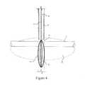
- FIG. 4is a schematic diagram of an exemplary electrode assembly for placement in a third well.
- FIG. 5is a side view of an exemplary drilling guidance system forming an electrical path through earth between an earth ground surface electrode and an electrode extending beyond the end of an existing underground well casing.
- FIG. 6is a side view of an exemplary drilling guidance system in which current flows along a conductor inside the entire length of a casing of a first well, through earth between an electrode extending from the end of the casing and a ground electrode.
- FIG. 7is a side view of an exemplary drilling guidance system in which current flows along the entire length of a casing of a first well, through earth between the distal end of the casing of a first well and an electrode lowered into a third well extending near to but not intersecting with the casing of the first well.
- FIG. 1schematically illustrates a typical well plan for drilling twin horizontal wells 10 , 12 .
- the wellsmay be drilled from a single drilling platform 16 , where the second well is drilled from a second position of the drilling rig, located a short distance from the position from which the first well was drilled.
- the inclination angles of wellsare built until they are horizontal, drilling into a desired deposit of, for example, heavy oil or tar.
- the first well 12is typically drilled and cased before drilling commences on the second horizontal well 10 .
- the casing or slotted liner for a wellis metallic and will conduct electric current.
- the horizontal portion of the first wellmay be below the second well by several meters, e.g., 4 to 10 meters.
- a directional surveyis made of the first well to locate the trajectory of the well and facilitate planning a surface location for a small, vertical borehole 20 which is a third well.
- This small boreholewill preferably nearly intersect 21 the first well at the distal termination end of the first well.
- the small vertical hole of the third wellmay be similar in size to a water well and may extend a few meters deeper than the first well.
- a conductive path between the casing 18 in the first well 10 and the electrode in the third wellmay be enhanced if needed by pumping a suitable conductive fluid into the third well 20 .
- the electrode 22is lowered into the vertical hole to provide a current path through the small well.
- the electrode 22electrically connects the casing or liner 18 (collectively “casing”) of the first well to a conductive path, e.g. a wire, in the small bore hole 20 .
- the conductive pathmay include earth between the electrode 22 extending from the third well and the distal end of the casing 18 of the first well.
- An above ground conductive pathe.g., wires 24 connects the surface ends of the third well 20 and the casing or liner 18 of the first well 10 to an alternating-current (AC) electrical generator 26 , or other source of time varying current.
- a hoist 27may lower and raise the wire and the electrode 22 in the third well.
- the hoistis connected to the insulated surface wire 24 and includes a spool of insulated wire to which the electrode 22 is attached.
- the hoistlowers the electrode 22 is preferably lowered to the depth of the first well casing.
- the electrical power from the generatordrives a current 28 that flows through the wire 24 , the third well 20 , electrode 22 , casing or liner of the first well 18 and is returned to the generator.
- the alternating-current 28produces an electromagnetic field 30 in the earth surrounding the casing 18 of the first well.
- the characteristics of an electromagnetic field from an AC conductive pathare well-known.
- the strength of the electromagnetic field 30is proportional to the alternating current applied by the generator.
- the magnitude of current in the casingmay be measured with precision by an amp meter, for example. Because the strength of the magnetic fields is proportional to the current, there is a well-defined relationship between the current, measured magnetic field strength at the new well and the distance between the new well and casing of the first well.
- the strength and direction of the magnetic fieldare indicative of the distance and direction to the casing of the first well.
- FIG. 2is a schematic view of the first and second wells at a cross-sectional plane along the vertical sections through the wells.
- the electromagnetic field 30emanates from the casing 18 of the first well 10 and into the surrounding earth.
- the second well 12is shown as the upper well however the position of the first and second well may be reversed depending on the drilling application.
- a sensor assembly 40 in the second wellsenses the earth's magnetic and gravity fields, and the electromagnetic field emanating from the first well.
- the acceptable drilling path of the second wellis defined by a typical acceptable zone 32 that is shown in cross-section in FIG. 2 .
- the acceptable zone 32may be a region that is usually centered in the range of 4 to 10 meters from the first well.
- the zone 32may have a short axis along a radius drawn from the upper well and a long axis perpendicular to a vertical plane through the upper well.
- the dimensions of the acceptable zonemay be plus or minus one meter along the short axis and plus or minus two meters along the long axis of the zone.
- the shape and dimensions of the acceptable zoneare known for each drilling application, but may differ depending on the application.
- the drilling trajectory for the second wellshould remain within the acceptable zone 32 for the entire length of the horizontal portion of the two wells.
- the drilling guidance systemwhich includes the sensor assembly 40 , is used to maintain the drilling trajectory of the second well within the acceptable zone. Whether the drilling trajectory of the second well 12 is within the acceptable zone 32 is determined based on the direction and strength of the electromagnetic field 30 along the second well path as sensed by the sensor assembly 40 .
- Measurements of the field intensity and field direction by the sensor assembly 40 , in the second wellprovide information sufficient to determine the direction to the first well and the distance between the two wells. This information is provided to the driller in a convenient form so that he can take appropriate action to maintain the trajectories of the two wells in the proper relationship.
- the sensor assembly 40is incorporated into the down hole probe of a wireline steering tool or MWD system for drilling the second well 12 . The sensor assembly thus guides the drilling of the second well for directional control of the drill path trajectory.
- the magnetic field (B) produced by a long straight conductor, such as the well casing,is proportional to the current (I) in the conductor and inversely proportional to the perpendicular distance (r) from the conductor.
- the distance (r) of the second bore hole from the casing of the first wellcan thus be determined based on the measurement of the current (I) in the casing and the magnetic field strength (B) at the second bore hole.
- FIG. 3is a schematic diagram of a component-type sensor assembly 40 (shown in a cut-away view) having the ability to discriminate field direction.
- Component-type magnetic sensorse.g., magnetometers, and accelerometers, are directional and survey sensors conventionally used in measurement-while-drilling (MWD) measurements.
- MWDmeasurement-while-drilling
- the sensor assembly 40moves through the second bore hole typically a few meters behind the drill bit and associated drilling equipment.
- the sensor assembly 40collects data used to determine the location of the second bore hole. This information issues to guide the drill bit along a desired drilling trajectory of the second well.
- the sensor assembly 40includes both standard orientation sensors, such as three orthogonal magnetometers 48 (to measure the magnetic field of the earth), three orthogonal accelerometers 51 (to measure the gravity field of the earth), and three highly-sensitive orthogonal alternating-field magnetic sensors 44 , 46 , 52 for detection of the electro magnetic field about the first (reference or producer) well.
- the magnetic sensorshave a component response pattern and are most sensitive to alternating magnetic field intensity corresponding to the frequency of the alternating current source. These sensors are mounted in a fixed relative orientation in the housing for the sensor assembly.
- a pair of radial component-magnetic sensors 44 46 and 52are arranged in the sensor assembly 40 such that their magnetically sensitive axes are mutually orthogonal.
- Each component sensor 44 , 46 and 52measures the relative magnetic field (B) strengths at the second well.
- the sensorswill each detect different field strengths due to their orthogonal orientations.
- the direction on the field (B)may be determined by the inverse tangent (tan ⁇ 1 ) of the ratio of the field strength sensed by the radial sensors 44 , 46 .
- the frame of reference for the radial sensors 44 , 46is the earth's gravity and magnetic north, determined by the conventional magnetic sensors 48 and the gravity sensors 51 .
- the direction to the conductor of currentis calculated by adding 90 degrees to the direction of the field at the point of measurement.
- the direction from the sensors to the first well and the perpendicular distance between the sensors and the first wellprovides sufficient information to guide the trajectory of the second well in the acceptable zone 32 .
- FIG. 4is a schematic illustration of an exemplary electrode 22 lowered into the small vertical hole 20 to the zone where conductive fluid has been introduced.
- the electrode 22includes metallic bow springs 50 e.g., an expandable mesh, that expand to contact the walls of the open borehole of the well 20 .
- the spring elements 50also retract to a size which slides through the temporary casing 53 of the vertical well 20 .
- the temporary casinginsures that the material around the borehole does not slough into the hole.
- the electrode 22is positioned near the first casing 18 at the nearest to a point of intersection 21 of the two wells.
- a conductive fluid in the third well 20seeps into the earth 56 surrounding the intersection 21 between wells.
- the conductive fluidenhances the electrical connectivity of the earth between the first casing and the electrode in the third well.
- the electrodeis connected to the insulated conductor wire 54 that extends through the well 20 and to the surface.
- the wire 54is connected via wire 24 to the return side of the generator.
- FIG. 5is a side view of an exemplary drilling guidance system 60 forming an electrical path 62 through a region of earth 63 between an ground surface electrode 64 and an electrode 66 extending beyond the end of an existing underground well casing 68 .
- the electrode 66extends a few meters, e.g., ten or more, beyond the distal end of the well casing 68 .
- the distance between the electrode 66 and the end of the well casingshould be sufficient to avoid current flowing from the electrode 66 , up through the casing of the first well and to the surface electrode.
- Electromagnetic fields generated by the low frequency of the AC current sourcee.g., preferably below 10 Hertz and most preferably at 5 Hertz, are not significantly attenuated by the slotted metallic casings in conventional wells.
- the electromagnetic fields generated by the current in the insulated wirepasses through the slots in the casing and into the earth. Eddy currents on the casing that could interfere with the electromagnetic field are not significant due to the low frequency of the AC source.
- An alternating current (AC) source 70applies an AC current to the return ground electrode 64 and to the underground electrode 66 to form an electrical current path including 62 , e.g., producing a diffuse electrical field, through the earth 63 between the ground electrode 64 at or near the surface and the underground electrode 66 .
- a wire 74 with an insulated coveringextends from the AC power source 70 , through the entire length (S) of the well casing 68 and through the extended borehole a distance past the distal end of the well casing to the electrode 66 , contacting the earth.
- the current path 62 through the earth and to the return ground electrode 64completes an electrical circuit that includes the AC source 70 , wire 74 and electrode 66 .
- the current path 62 through the earth and to the return ground electrode 64completes an electrical circuit that includes the AC source 70 , wire 74 and electrode 66 .
- the wire 74 extending down through the first well casing to the underground electrode 66is insulated and has steel armor to provide mechanical strength to the wire. Electromagnetic fields from the wire 74 pass through insulation, armor and the well casing 68 and into the earth. The steel armor provides mechanical strength to the wire.
- the surface wire 75 to the wire 74 and the surface wire 24 and wire 112 extending down the third wellmay have shielding to prevent electromagnetic fields from these wires from generating spurious electromagnetic fields that enter the earth. Further, the connections between the current source and the wire 74 and the current source and surface wire 78 are established to avoid current leakage to ground. Care is taken in setting up the electrical circuit for the drilling guidance system to ensure that current does not unintentionally leak to ground and that unwanted electromagnetic fields are not created that may affect the data collected by the sensors 88 .
- the alternating current in the wire 74generates an electromagnetic field that extends around and beyond the casing 68 of the first well.
- a known current valueis applied to the wire 74 and electrode 66 . Knowing the current in the wire 74 , a calculation, e.g. an application of Ampere's Law, can be made to estimate the electromagnetic field at any given distance from the wire 74 and the well casing 68 . This calculated distance can be used to guide the drilling of a second well.
- FIG. 6is a side view of the drilling guidance system 60 in which a second well 80 is being drilled parallel to the first well 68 .
- a drilling rig 82which may be the same rig used for the first well, guides a drill head 84 forming the second well along a trajectory 86 that is parallel to the first well casing 68 .
- Electromagnetic sensors 88 in the second well and behind the drill headdetect the electromagnetic field from the first well 68 and wire 80 in the well.
- a current path 90extends from the AC current source 70 , along the wire 74 extending the length of the first well casing 68 and out from the distal end of that casing to the electrode 66 , through the diffuse electrical path 62 in the earth 63 between the electrode 66 and return ground electrode 64 , and from the return ground electrode along the return wire 92 to the source 70 .
- the AC sensors 88are positioned approximately 18 or 20 meters behind the bit, thus will not be affected by the more concentrated current in the region where the current leaves the electrode and becomes more and more diffused as it moves away from the electrode. In practice, the AC sensors in the Injector well will be located some 40 or more meters behind the electrode at the closest point, which will be near the termination of drilling of the (lower) Injector well.
- the calculation of the estimated electromagnetic field strength at a distance from the first well casingis used to estimate the distance from the first well casing of a second well trajectory 86 being drilled parallel to the first well casing 68 . Because the strength of the magnetic field at any distance from first well casing can be calculated, the measured field strength from the sensors 88 can be used to determine the distance between the second well and the first well. This information regarding the distance between the positions of the electromagnetic sensors 88 in the second well will be used to guide the trajectory of the drilling head 84 along a path parallel to the first well casing.
- the calculation of the electromagnetic field around the first well casingmay also account for other elements of the AC circuit that contribute to the magnetic field detected by the sensors 88 in the second well.
- electromagnetic fields that extend into the groundmay be produced by the surface mounted return wire 92 carrying current between the AC power source 70 and the return ground electrode 64 , e.g., a rod.
- the current-conducting wire 74 in the vertical section 94 of the first well casing 68produces an electromagnetic field in the earth.
- Calculations of expected electrical field strength from a variety of current sources, e.g., wire 92 , the vertical portion 84 of wire 74 and the diffuse electrical current 62 in the earth region 63can be accomplished with known computational techniques for calculating electrical field strengths.
- the calculations of the expected field intensity and the measurement of the field intensity by sensors in the second wellare conducted in real time and substantially simultaneously.
- the current 62 in the region of earth 63 between the electrode and the ground rodis so thoroughly diffused that the field resulting from this current will not be detected at by the AC sensors 88 at their positions in the second well. Thus, the current 62 can be ignored for purposes of calculating the electromagnetic field around the casing of the first well.
- the electromagnetic field strength of the current 62 in the earth 63may relatively strong in the vicinity of the distal end of the first well. However, it is not needed to measure the field at the distal end of the first well because this point is at or near the end of the second drilling path 86 . At the end of the path there is likely to much less need, if any, to monitor the field because the drilling path is nearly complete and the trajectory will not significantly change further.
- Deployment of the electrode outside the first well (the Producer well) 68 casing into open holemay be done in a variety of ways.
- the electrodemay be pumped down through whatever tubular is used to run it into the hole, pushed into position with an extension of the tubing or drill pipe used to lower it into the hole, or it may be pushed into place with an extended well tractor. Yet another possibility is the use of coiled tubing to push it into place.
- this methodmay well be more accurate than the three-well method because of the lossless current conduction by the wire inside the pipe, with no loss of accuracy due to poor information about the conductivity of formations surrounding the casing.
- FIG. 7is a side view of another exemplary drilling guidance system 100 in which current flows along the entire length of a conductive casing 102 of a first well, through a region of earth 104 between a distal end 106 of the casing and a return ground electrode 108 lowered into a third well casing 110 extending near to but not intersecting with the casing 102 of the first well.
- a current source 70applies current directly to the conductive casing 102 of the first well and to a conductive return wire 112 extending along the surface from the source 70 to and down the third well 110 to the return ground electrode 108 .
- the return ground electrode 108extends beyond the distal end of the casing of the third well into open borehole in the earth and is connected to the return wire that extends through the casing, which is preferably non-conductive, of the third well.
- a diffuse electrical current path 115is formed in the earth between the return electrode 108 and the casing of the first well. This electrical path is included in the current path 114 extending from the source 70 , casing 102 of the first well, return electrode 108 and return wire 112 .
- the return electrodeis positioned close to the first well casing (and preferably in contact with the casing) to reduce the electrical path through earth between the casing and the return electrode.
- the current path 114includes the current in a horizontal portion of the casing 102 of the first well which generates an electromagnetic field around the casing that is detected by sensors 88 in a second well 80 being drilled by a drill head 84 following a desired drilling trajectory 86 .
- the distance between these sensors in the second well 80can be used to calculate the distance between the first well and the second well, from the location of the sensors.
Landscapes
- Geology (AREA)
- Life Sciences & Earth Sciences (AREA)
- Engineering & Computer Science (AREA)
- Physics & Mathematics (AREA)
- Mining & Mineral Resources (AREA)
- Environmental & Geological Engineering (AREA)
- Fluid Mechanics (AREA)
- General Life Sciences & Earth Sciences (AREA)
- Geochemistry & Mineralogy (AREA)
- Electromagnetism (AREA)
- Geophysics (AREA)
- Geophysics And Detection Of Objects (AREA)
- Earth Drilling (AREA)
Abstract
Description
B=•I/(2πr)
Claims (3)
Priority Applications (4)
| Application Number | Priority Date | Filing Date | Title |
|---|---|---|---|
| US12/352,288US8418782B2 (en) | 2004-11-30 | 2009-01-12 | Method and system for precise drilling guidance of twin wells |
| AU2010200041AAU2010200041B2 (en) | 2009-01-12 | 2010-01-06 | Method and system for precise drilling guidance of twin wells |
| CA2689815ACA2689815C (en) | 2009-01-12 | 2010-01-07 | Method and system for precise drilling guidance of twin wells |
| RU2010100112/03ARU2515930C2 (en) | 2009-01-12 | 2010-01-11 | Method for drilling trajectory control for second well passing close to first well (versions) |
Applications Claiming Priority (2)
| Application Number | Priority Date | Filing Date | Title |
|---|---|---|---|
| US10/998,781US7475741B2 (en) | 2004-11-30 | 2004-11-30 | Method and system for precise drilling guidance of twin wells |
| US12/352,288US8418782B2 (en) | 2004-11-30 | 2009-01-12 | Method and system for precise drilling guidance of twin wells |
Related Parent Applications (1)
| Application Number | Title | Priority Date | Filing Date |
|---|---|---|---|
| US10/998,781Continuation-In-PartUS7475741B2 (en) | 2004-11-30 | 2004-11-30 | Method and system for precise drilling guidance of twin wells |
Publications (2)
| Publication Number | Publication Date |
|---|---|
| US20090178850A1 US20090178850A1 (en) | 2009-07-16 |
| US8418782B2true US8418782B2 (en) | 2013-04-16 |
Family
ID=40849685
Family Applications (1)
| Application Number | Title | Priority Date | Filing Date |
|---|---|---|---|
| US12/352,288Expired - Fee RelatedUS8418782B2 (en) | 2004-11-30 | 2009-01-12 | Method and system for precise drilling guidance of twin wells |
Country Status (1)
| Country | Link |
|---|---|
| US (1) | US8418782B2 (en) |
Cited By (7)
| Publication number | Priority date | Publication date | Assignee | Title |
|---|---|---|---|---|
| CN104265270A (en)* | 2014-07-30 | 2015-01-07 | 中国石油集团钻井工程技术研究院 | Carbonatite fissure cavern drilling track design and control method |
| CN104847263A (en)* | 2015-04-30 | 2015-08-19 | 中煤科工集团西安研究院有限公司 | Coal bed methane far-end butt joint horizontal well drilling method |
| US9938821B2 (en) | 2013-08-29 | 2018-04-10 | Halliburton Energy Services, Inc. | Systems and methods for casing detection using resonant structures |
| WO2019125475A1 (en)* | 2017-12-21 | 2019-06-27 | Halliburton Energy Services, Inc. | Correction method for end-of-pipe effect on magnetic ranging |
| US10408044B2 (en) | 2014-12-31 | 2019-09-10 | Halliburton Energy Services, Inc. | Methods and systems employing fiber optic sensors for ranging |
| US10557960B2 (en)* | 2014-10-10 | 2020-02-11 | Halliburton Energy Services, Inc. | Well ranging apparatus, methods, and systems |
| US10920563B2 (en)* | 2018-04-17 | 2021-02-16 | Timothy B. Mower | Horizontal drilling device and method of using the same |
Families Citing this family (26)
| Publication number | Priority date | Publication date | Assignee | Title |
|---|---|---|---|---|
| US8307915B2 (en) | 2008-04-10 | 2012-11-13 | Schlumberger Technology Corporation | System and method for drilling multilateral wells using magnetic ranging while drilling |
| US8827005B2 (en)* | 2008-04-17 | 2014-09-09 | Schlumberger Technology Corporation | Method for drilling wells in close relationship using magnetic ranging while drilling |
| CA2800148C (en)* | 2010-06-29 | 2015-06-23 | Halliburton Energy Services, Inc. | Method and apparatus for sensing elongated subterranean anomalies |
| US10145231B2 (en) | 2012-12-07 | 2018-12-04 | Halliburton Energy Services, Inc. | Surface excitation ranging system for SAGD application |
| EP2920411B1 (en)* | 2012-12-07 | 2023-12-13 | Halliburton Energy Services, Inc. | Drilling parallel wells for sagd and relief |
| CA2900806C (en) | 2013-03-11 | 2018-01-02 | Halliburton Energy Services, Inc. | Downhole ranging from multiple wellbores |
| US9506326B2 (en)* | 2013-07-11 | 2016-11-29 | Halliburton Energy Services, Inc. | Rotationally-independent wellbore ranging |
| CN103470237B (en)* | 2013-09-06 | 2016-04-06 | 兴和鹏能源技术(北京)股份有限公司 | Unconventional oppositely to the method for wearing and rotating signal omniselector |
| CN105874163B (en)* | 2013-09-30 | 2019-12-31 | 信远达石油服务有限公司 | Drilling Auxiliary System |
| US10520628B2 (en)* | 2013-09-30 | 2019-12-31 | Halliburton Energy Services, Inc. | Downhole gradiometric ranging for T-intersection and well avoidance utilizing transmitters and receivers having magnetic dipoles |
| US10208584B2 (en) | 2013-12-18 | 2019-02-19 | Halliburton Energy Services, Inc. | Fiber optic current monitoring for electromagnetic ranging |
| WO2016022190A1 (en)* | 2014-08-08 | 2016-02-11 | Halliburton Energy Services, Inc. | Well ranging apparatus, methods, and systems |
| CA2954657C (en) | 2014-08-11 | 2019-09-24 | Halliburton Energy Services, Inc. | Well ranging apparatus, systems, and methods |
| WO2016048307A1 (en)* | 2014-09-24 | 2016-03-31 | Halliburton Energy Services Inc. | Surface ranging technique with a surface detector |
| CN104695863B (en)* | 2015-01-27 | 2017-05-10 | 新奥科技发展有限公司 | Method for correcting track of horizontal well |
| CN104895499B (en)* | 2015-05-19 | 2018-07-06 | 新奥科技发展有限公司 | Horizontal well path bearing calibration |
| EP3337953B1 (en) | 2015-10-20 | 2019-09-04 | Halliburton Energy Services, Inc. | Passive ranging to a target well using a fiber optic ranging assembly |
| US9803473B2 (en)* | 2015-10-23 | 2017-10-31 | Schlumberger Technology Corporation | Downhole electromagnetic telemetry receiver |
| EP3359777B1 (en) | 2015-12-18 | 2021-12-22 | Halliburton Energy Services, Inc. | Systems and methods to calibrate individual component measurement |
| CA3033161C (en) | 2016-09-19 | 2021-03-09 | Halliburton Energy Services, Inc. | Directional button excitation for ranging applications |
| US10465496B2 (en) | 2016-09-26 | 2019-11-05 | Halliburton Energy Services, Inc. | Sleeve excitation for ranging measurements using electrode sources |
| CN108316859B (en)* | 2018-02-07 | 2019-07-23 | 中石化江汉石油工程有限公司 | Shale gas horizontal well enters method for controlling trajectory before target with geosteering is bored |
| CN110159244A (en)* | 2019-05-10 | 2019-08-23 | 刘森林 | Sylvite ore solution mining method |
| AU2021107346B4 (en)* | 2020-11-02 | 2022-05-19 | Timothy Mcclure | Method for Installing an Earthing System |
| CN112855103A (en)* | 2021-04-01 | 2021-05-28 | 中国石油天然气股份有限公司 | Recovery method of super heavy oil reservoir and arrangement method of steam injection well |
| CN116066078B (en)* | 2021-11-02 | 2025-08-19 | 中国石油化工集团有限公司 | Electric measurement method for radial horizontal well track |
Citations (41)
| Publication number | Priority date | Publication date | Assignee | Title |
|---|---|---|---|---|
| US3285350A (en)* | 1964-04-23 | 1966-11-15 | Henderson John Keller | Method and apparatus for controllably drilling off-vertical holes |
| US3725777A (en) | 1971-06-07 | 1973-04-03 | Shell Oil Co | Method for determining distance and direction to a cased borehole using measurements made in an adjacent borehole |
| US4072200A (en) | 1976-05-12 | 1978-02-07 | Morris Fred J | Surveying of subterranean magnetic bodies from an adjacent off-vertical borehole |
| US4458767A (en) | 1982-09-28 | 1984-07-10 | Mobil Oil Corporation | Method for directionally drilling a first well to intersect a second well |
| US4465140A (en) | 1982-09-28 | 1984-08-14 | Mobil Oil Corporation | Method for the magnetization of well casing |
| US4593770A (en) | 1984-11-06 | 1986-06-10 | Mobil Oil Corporation | Method for preventing the drilling of a new well into one of a plurality of production wells |
| US4710708A (en) | 1981-04-27 | 1987-12-01 | Develco | Method and apparatus employing received independent magnetic field components of a transmitted alternating magnetic field for determining location |
| US4791373A (en) | 1986-10-08 | 1988-12-13 | Kuckes Arthur F | Subterranean target location by measurement of time-varying magnetic field vector in borehole |
| US4875014A (en) | 1988-07-20 | 1989-10-17 | Tensor, Inc. | System and method for locating an underground probe having orthogonally oriented magnetometers |
| US5064006A (en) | 1988-10-28 | 1991-11-12 | Magrange, Inc | Downhole combination tool |
| US5074365A (en) | 1990-09-14 | 1991-12-24 | Vector Magnetics, Inc. | Borehole guidance system having target wireline |
| US5155916A (en) | 1991-03-21 | 1992-10-20 | Scientific Drilling International | Error reduction in compensation of drill string interference for magnetic survey tools |
| US5218301A (en) | 1991-10-04 | 1993-06-08 | Vector Magnetics | Method and apparatus for determining distance for magnetic and electric field measurements |
| US5230387A (en) | 1988-10-28 | 1993-07-27 | Magrange, Inc. | Downhole combination tool |
| US5343152A (en)* | 1992-11-02 | 1994-08-30 | Vector Magnetics | Electromagnetic homing system using MWD and current having a funamental wave component and an even harmonic wave component being injected at a target well |
| US5398421A (en) | 1990-12-12 | 1995-03-21 | Institut Francais Du Petrole Et Societe | Method for connecting magnetic measurements performed in a well through a measuring device in order to determine the azimuth thereof |
| US5435069A (en) | 1993-01-13 | 1995-07-25 | Shell Oil Company | Method for determining borehole direction |
| US5452518A (en) | 1993-11-19 | 1995-09-26 | Baker Hughes Incorporated | Method of correcting for axial error components in magnetometer readings during wellbore survey operations |
| US5485089A (en) | 1992-11-06 | 1996-01-16 | Vector Magnetics, Inc. | Method and apparatus for measuring distance and direction by movable magnetic field source |
| US5512830A (en) | 1993-11-09 | 1996-04-30 | Vector Magnetics, Inc. | Measurement of vector components of static field perturbations for borehole location |
| US5564193A (en) | 1993-11-17 | 1996-10-15 | Baker Hughes Incorporated | Method of correcting for axial and transverse error components in magnetometer readings during wellbore survey operations |
| US5589775A (en) | 1993-11-22 | 1996-12-31 | Vector Magnetics, Inc. | Rotating magnet for distance and direction measurements from a first borehole to a second borehole |
| US5657826A (en) | 1994-11-15 | 1997-08-19 | Vector Magnetics, Inc. | Guidance system for drilling boreholes |
| US5676212A (en)* | 1996-04-17 | 1997-10-14 | Vector Magnetics, Inc. | Downhole electrode for well guidance system |
| US5725059A (en) | 1995-12-29 | 1998-03-10 | Vector Magnetics, Inc. | Method and apparatus for producing parallel boreholes |
| US5923170A (en) | 1997-04-04 | 1999-07-13 | Vector Magnetics, Inc. | Method for near field electromagnetic proximity determination for guidance of a borehole drill |
| US6152246A (en) | 1998-12-02 | 2000-11-28 | Noble Drilling Services, Inc. | Method of and system for monitoring drilling parameters |
| US20020112856A1 (en) | 2001-02-16 | 2002-08-22 | Van Steenwyk Donald H. | Method for magnetizing wellbore tubulars |
| US6466020B2 (en) | 2001-03-19 | 2002-10-15 | Vector Magnetics, Llc | Electromagnetic borehole surveying method |
| US20030041661A1 (en) | 2001-09-04 | 2003-03-06 | Van Steenwyk Donald H. | Inertially-stabilized magnetometer measuring apparatus for use in a borehole rotary environment |
| US6530154B2 (en) | 2001-07-19 | 2003-03-11 | Scientific Drilling International | Method to detect deviations from a wellplan while drilling in the presence of magnetic interference |
| US6608565B1 (en) | 2000-01-27 | 2003-08-19 | Scientific Drilling International | Downward communication in a borehole through drill string rotary modulation |
| US6626252B1 (en) | 2002-04-03 | 2003-09-30 | Vector Magnetics Llc | Two solenoid guide system for horizontal boreholes |
| US20040020691A1 (en) | 1999-08-05 | 2004-02-05 | Baker Hughes Incorporated | Continuous wellbore drilling system with stationary sensor measurements |
| US6736222B2 (en) | 2001-11-05 | 2004-05-18 | Vector Magnetics, Llc | Relative drill bit direction measurement |
| US20040160223A1 (en) | 2003-02-18 | 2004-08-19 | Pathfinder Energy Services, Inc. | Passive ranging techniques in borehole surveying |
| US20040159466A1 (en) | 2000-05-05 | 2004-08-19 | Weatherford/Lamb, Inc. | Apparatus and methods for forming a lateral wellbore |
| US6927741B2 (en) | 2001-11-15 | 2005-08-09 | Merlin Technology, Inc. | Locating technique and apparatus using an approximated dipole signal |
| US7219749B2 (en) | 2004-09-28 | 2007-05-22 | Vector Magnetics Llc | Single solenoid guide system |
| US7475741B2 (en) | 2004-11-30 | 2009-01-13 | General Electric Company | Method and system for precise drilling guidance of twin wells |
| US20090120691A1 (en) | 2004-11-30 | 2009-05-14 | General Electric Company | Systems and methods for guiding the drilling of a horizontal well |
- 2009
- 2009-01-12USUS12/352,288patent/US8418782B2/ennot_activeExpired - Fee Related
Patent Citations (44)
| Publication number | Priority date | Publication date | Assignee | Title |
|---|---|---|---|---|
| US3285350A (en)* | 1964-04-23 | 1966-11-15 | Henderson John Keller | Method and apparatus for controllably drilling off-vertical holes |
| US3725777A (en) | 1971-06-07 | 1973-04-03 | Shell Oil Co | Method for determining distance and direction to a cased borehole using measurements made in an adjacent borehole |
| US4072200A (en) | 1976-05-12 | 1978-02-07 | Morris Fred J | Surveying of subterranean magnetic bodies from an adjacent off-vertical borehole |
| US4710708A (en) | 1981-04-27 | 1987-12-01 | Develco | Method and apparatus employing received independent magnetic field components of a transmitted alternating magnetic field for determining location |
| US4458767A (en) | 1982-09-28 | 1984-07-10 | Mobil Oil Corporation | Method for directionally drilling a first well to intersect a second well |
| US4465140A (en) | 1982-09-28 | 1984-08-14 | Mobil Oil Corporation | Method for the magnetization of well casing |
| US4593770A (en) | 1984-11-06 | 1986-06-10 | Mobil Oil Corporation | Method for preventing the drilling of a new well into one of a plurality of production wells |
| US4791373A (en) | 1986-10-08 | 1988-12-13 | Kuckes Arthur F | Subterranean target location by measurement of time-varying magnetic field vector in borehole |
| US4875014A (en) | 1988-07-20 | 1989-10-17 | Tensor, Inc. | System and method for locating an underground probe having orthogonally oriented magnetometers |
| US5230387A (en) | 1988-10-28 | 1993-07-27 | Magrange, Inc. | Downhole combination tool |
| US5064006A (en) | 1988-10-28 | 1991-11-12 | Magrange, Inc | Downhole combination tool |
| US5074365A (en) | 1990-09-14 | 1991-12-24 | Vector Magnetics, Inc. | Borehole guidance system having target wireline |
| US5398421A (en) | 1990-12-12 | 1995-03-21 | Institut Francais Du Petrole Et Societe | Method for connecting magnetic measurements performed in a well through a measuring device in order to determine the azimuth thereof |
| US5155916A (en) | 1991-03-21 | 1992-10-20 | Scientific Drilling International | Error reduction in compensation of drill string interference for magnetic survey tools |
| US5218301A (en) | 1991-10-04 | 1993-06-08 | Vector Magnetics | Method and apparatus for determining distance for magnetic and electric field measurements |
| US5343152A (en)* | 1992-11-02 | 1994-08-30 | Vector Magnetics | Electromagnetic homing system using MWD and current having a funamental wave component and an even harmonic wave component being injected at a target well |
| US5485089A (en) | 1992-11-06 | 1996-01-16 | Vector Magnetics, Inc. | Method and apparatus for measuring distance and direction by movable magnetic field source |
| US5435069A (en) | 1993-01-13 | 1995-07-25 | Shell Oil Company | Method for determining borehole direction |
| US5512830A (en) | 1993-11-09 | 1996-04-30 | Vector Magnetics, Inc. | Measurement of vector components of static field perturbations for borehole location |
| US5564193A (en) | 1993-11-17 | 1996-10-15 | Baker Hughes Incorporated | Method of correcting for axial and transverse error components in magnetometer readings during wellbore survey operations |
| US5452518A (en) | 1993-11-19 | 1995-09-26 | Baker Hughes Incorporated | Method of correcting for axial error components in magnetometer readings during wellbore survey operations |
| US5589775A (en) | 1993-11-22 | 1996-12-31 | Vector Magnetics, Inc. | Rotating magnet for distance and direction measurements from a first borehole to a second borehole |
| US5657826A (en) | 1994-11-15 | 1997-08-19 | Vector Magnetics, Inc. | Guidance system for drilling boreholes |
| US5725059A (en) | 1995-12-29 | 1998-03-10 | Vector Magnetics, Inc. | Method and apparatus for producing parallel boreholes |
| US5676212A (en)* | 1996-04-17 | 1997-10-14 | Vector Magnetics, Inc. | Downhole electrode for well guidance system |
| US5923170A (en) | 1997-04-04 | 1999-07-13 | Vector Magnetics, Inc. | Method for near field electromagnetic proximity determination for guidance of a borehole drill |
| US6152246A (en) | 1998-12-02 | 2000-11-28 | Noble Drilling Services, Inc. | Method of and system for monitoring drilling parameters |
| US20040020691A1 (en) | 1999-08-05 | 2004-02-05 | Baker Hughes Incorporated | Continuous wellbore drilling system with stationary sensor measurements |
| US6608565B1 (en) | 2000-01-27 | 2003-08-19 | Scientific Drilling International | Downward communication in a borehole through drill string rotary modulation |
| US20040159466A1 (en) | 2000-05-05 | 2004-08-19 | Weatherford/Lamb, Inc. | Apparatus and methods for forming a lateral wellbore |
| US20020112856A1 (en) | 2001-02-16 | 2002-08-22 | Van Steenwyk Donald H. | Method for magnetizing wellbore tubulars |
| US6466020B2 (en) | 2001-03-19 | 2002-10-15 | Vector Magnetics, Llc | Electromagnetic borehole surveying method |
| US6530154B2 (en) | 2001-07-19 | 2003-03-11 | Scientific Drilling International | Method to detect deviations from a wellplan while drilling in the presence of magnetic interference |
| US6651496B2 (en) | 2001-09-04 | 2003-11-25 | Scientific Drilling International | Inertially-stabilized magnetometer measuring apparatus for use in a borehole rotary environment |
| US20030220743A1 (en) | 2001-09-04 | 2003-11-27 | Scientific Drilling International | Inertially-stabilized magnetometer measuring apparatus for use in a borehole rotary environment |
| US20030041661A1 (en) | 2001-09-04 | 2003-03-06 | Van Steenwyk Donald H. | Inertially-stabilized magnetometer measuring apparatus for use in a borehole rotary environment |
| US6736222B2 (en) | 2001-11-05 | 2004-05-18 | Vector Magnetics, Llc | Relative drill bit direction measurement |
| US6927741B2 (en) | 2001-11-15 | 2005-08-09 | Merlin Technology, Inc. | Locating technique and apparatus using an approximated dipole signal |
| US6626252B1 (en) | 2002-04-03 | 2003-09-30 | Vector Magnetics Llc | Two solenoid guide system for horizontal boreholes |
| US6814163B2 (en) | 2002-04-03 | 2004-11-09 | Vector Magnetics, Llc | Two solenoid guide system for horizontal boreholes |
| US20040160223A1 (en) | 2003-02-18 | 2004-08-19 | Pathfinder Energy Services, Inc. | Passive ranging techniques in borehole surveying |
| US7219749B2 (en) | 2004-09-28 | 2007-05-22 | Vector Magnetics Llc | Single solenoid guide system |
| US7475741B2 (en) | 2004-11-30 | 2009-01-13 | General Electric Company | Method and system for precise drilling guidance of twin wells |
| US20090120691A1 (en) | 2004-11-30 | 2009-05-14 | General Electric Company | Systems and methods for guiding the drilling of a horizontal well |
Non-Patent Citations (2)
| Title |
|---|
| MagTraC Scientific Drilling brochure, (five pages), (prior to Jun. 2004). |
| MagTraC Scientific Drilling brochure, MagTraC, (one page), (Jun. 2003). |
Cited By (9)
| Publication number | Priority date | Publication date | Assignee | Title |
|---|---|---|---|---|
| US9938821B2 (en) | 2013-08-29 | 2018-04-10 | Halliburton Energy Services, Inc. | Systems and methods for casing detection using resonant structures |
| CN104265270A (en)* | 2014-07-30 | 2015-01-07 | 中国石油集团钻井工程技术研究院 | Carbonatite fissure cavern drilling track design and control method |
| CN104265270B (en)* | 2014-07-30 | 2015-10-28 | 中国石油集团钻井工程技术研究院 | A kind of carbonate rock fractured cave wellbore trace design and control method |
| US10557960B2 (en)* | 2014-10-10 | 2020-02-11 | Halliburton Energy Services, Inc. | Well ranging apparatus, methods, and systems |
| US10408044B2 (en) | 2014-12-31 | 2019-09-10 | Halliburton Energy Services, Inc. | Methods and systems employing fiber optic sensors for ranging |
| CN104847263A (en)* | 2015-04-30 | 2015-08-19 | 中煤科工集团西安研究院有限公司 | Coal bed methane far-end butt joint horizontal well drilling method |
| WO2019125475A1 (en)* | 2017-12-21 | 2019-06-27 | Halliburton Energy Services, Inc. | Correction method for end-of-pipe effect on magnetic ranging |
| US11346208B2 (en) | 2017-12-21 | 2022-05-31 | Halliburton Energy Services, Inc. | Correction method for end-of-pipe effect on magnetic ranging |
| US10920563B2 (en)* | 2018-04-17 | 2021-02-16 | Timothy B. Mower | Horizontal drilling device and method of using the same |
Also Published As
| Publication number | Publication date |
|---|---|
| US20090178850A1 (en) | 2009-07-16 |
Similar Documents
| Publication | Publication Date | Title |
|---|---|---|
| US8418782B2 (en) | Method and system for precise drilling guidance of twin wells | |
| US7475741B2 (en) | Method and system for precise drilling guidance of twin wells | |
| US9890629B2 (en) | Method and apparatus for optimizing magnetic signals and detecting casing and resistivity | |
| CA2721443C (en) | Magnetic ranging while drilling using an electric dipole source and a magnetic field sensor | |
| US7782060B2 (en) | Integrated electrode resistivity and EM telemetry tool | |
| US8113298B2 (en) | Wireline communication system for deep wells | |
| US5676212A (en) | Downhole electrode for well guidance system | |
| US20090120691A1 (en) | Systems and methods for guiding the drilling of a horizontal well | |
| US4700142A (en) | Method for determining the location of a deep-well casing by magnetic field sensing | |
| US8810247B2 (en) | Electromagnetic orientation system for deep wells | |
| US8289024B2 (en) | Method and apparatus for locating well casings from an adjacent wellbore | |
| US4372398A (en) | Method of determining the location of a deep-well casing by magnetic field sensing | |
| US10458227B2 (en) | Well completion with single wire guidance system | |
| CA2689815C (en) | Method and system for precise drilling guidance of twin wells | |
| Tarr et al. | Use of new ranging tool to position a vertical well adjacent to a horizontal well | |
| CA2689819A1 (en) | Systems and methods for guiding the drilling of a horizontal well |
Legal Events
| Date | Code | Title | Description |
|---|---|---|---|
| AS | Assignment | Owner name:GENERAL ELECTRIC COMPANY, NEW YORK Free format text:ASSIGNMENT OF ASSIGNORS INTEREST;ASSIGNORS:WATERS, ROBERT L.;MEADOR, EDWIN;REEL/FRAME:022442/0886 Effective date:20090317 | |
| STCF | Information on status: patent grant | Free format text:PATENTED CASE | |
| FPAY | Fee payment | Year of fee payment:4 | |
| AS | Assignment | Owner name:GE ENERGY OIL FIELD TECHNOLOGY INC., LOUISIANA Free format text:ASSIGNMENT OF ASSIGNORS INTEREST;ASSIGNORS:GENERAL ELECTRIC COMPANY;BAKER HUGHES, A GE COMPANY, LLC;REEL/FRAME:049151/0098 Effective date:20190227 Owner name:PRIME DOWNHOLE MANUFACTURING LLC, TEXAS Free format text:ASSIGNMENT OF ASSIGNORS INTEREST;ASSIGNOR:GE ENERGY OILFIELD TECHNOLOGY, INC.;REEL/FRAME:049151/0126 Effective date:20190312 | |
| MAFP | Maintenance fee payment | Free format text:PAYMENT OF MAINTENANCE FEE, 8TH YEAR, LARGE ENTITY (ORIGINAL EVENT CODE: M1552); ENTITY STATUS OF PATENT OWNER: LARGE ENTITY Year of fee payment:8 | |
| AS | Assignment | Owner name:CALLODINE COMMERCIAL FINANCE, LLC, AS ADMINISTRATIVE AGENT, MASSACHUSETTS Free format text:SECURITY INTEREST;ASSIGNOR:BLACK DIAMOND OILFIELD RENTALS LLC;REEL/FRAME:061372/0012 Effective date:20220819 | |
| AS | Assignment | Owner name:CALLODINE COMMERCIAL FINANCE, LLC, AS ADMINISTRATIVE AGENT, MASSACHUSETTS Free format text:SECURITY INTEREST;ASSIGNOR:BLACK DIAMOND OILFIELD RENTALS LLC;REEL/FRAME:061629/0891 Effective date:20220819 | |
| FEPP | Fee payment procedure | Free format text:MAINTENANCE FEE REMINDER MAILED (ORIGINAL EVENT CODE: REM.); ENTITY STATUS OF PATENT OWNER: LARGE ENTITY | |
| LAPS | Lapse for failure to pay maintenance fees | Free format text:PATENT EXPIRED FOR FAILURE TO PAY MAINTENANCE FEES (ORIGINAL EVENT CODE: EXP.); ENTITY STATUS OF PATENT OWNER: LARGE ENTITY | |
| STCH | Information on status: patent discontinuation | Free format text:PATENT EXPIRED DUE TO NONPAYMENT OF MAINTENANCE FEES UNDER 37 CFR 1.362 | |
| FP | Lapsed due to failure to pay maintenance fee | Effective date:20250416 |