US8417493B2 - Scanning dental models - Google Patents
Scanning dental modelsDownload PDFInfo
- Publication number
- US8417493B2 US8417493B2US12/715,999US71599910AUS8417493B2US 8417493 B2US8417493 B2US 8417493B2US 71599910 AUS71599910 AUS 71599910AUS 8417493 B2US8417493 B2US 8417493B2
- Authority
- US
- United States
- Prior art keywords
- scanning
- plate module
- alignment
- physical model
- coordinate system
- Prior art date
- Legal status (The legal status is an assumption and is not a legal conclusion. Google has not performed a legal analysis and makes no representation as to the accuracy of the status listed.)
- Expired - Fee Related, expires
Links
Images


Classifications
- G—PHYSICS
- G06—COMPUTING OR CALCULATING; COUNTING
- G06T—IMAGE DATA PROCESSING OR GENERATION, IN GENERAL
- G06T17/00—Three dimensional [3D] modelling, e.g. data description of 3D objects
- A—HUMAN NECESSITIES
- A61—MEDICAL OR VETERINARY SCIENCE; HYGIENE
- A61C—DENTISTRY; APPARATUS OR METHODS FOR ORAL OR DENTAL HYGIENE
- A61C9/00—Impression cups, i.e. impression trays; Impression methods
- A61C9/004—Means or methods for taking digitized impressions
Definitions
- This applicationrelates in general to a method and apparatus for providing electronic models from scanning physical objects, and more particularly to a method and apparatus for generating an electronic model for a dental impression having a common coordinate system.
- the scanning of the dental impression of a patient's mouthproduces two separate electronic models that need to be integrated into a single frame of reference if the two models are to be used to interact with each other.
- This single frame of referencecorresponds to a single coordinate system in which all known points in the two electronic models for the upper and lower jaws are specified in a single coordinate system.
- a simple mechanism to determine common points in each of the two electronic model coordinate systemssuch that the translation of one coordinate system into the other coordinate system may be performed easily.
- the two electronic modelswere separately generated after which a user would identify common points in the opposing model. Such a system is prone to error of a user in selecting the common points and as such is not readily repeatable.
- This applicationrelates in general to a method and apparatus for generating an electronic model for a dental impression having a common coordinate system.
- One possible embodiment of the present inventionis a system for generating an electronic model for a dental impression having a common coordinate system.
- the systemincludes two scanning apparatus for positioning physical objects within a scanning device when generating an electronic model corresponding to each of the physical objects; a data processing system for processing the electronic models corresponding to each of the physical objects to possess polygonal mesh representations of the physical objects within a common coordinate system.
- the scanning apparatuscomprises a scanning base plate module for coupling the scanning apparatus to the scanning device and a physical model plate module to coupling the physical object to the scanning base plate module within a coordinate system of the scanning device.
- Another aspect of the present inventionis a method for generating an electronic model for a dental impression having a common coordinate system.
- the methodmounts physical models onto corresponding scanning apparatus, the scanning apparatus positions the physical models within a coordinate system of a scanning device; generates an electronic model for each physical model, the electronic models correspond to polygonal mesh representations of scanned position data; positions each of the scanning apparatus into a desired position in which the physical models are positioned relative to each other as the objects corresponding to the physical models interact with each other to generate a composite scanning apparatus; scans a reference point on one or more scanning apparatus within the combined scanning apparatus that are not coupled to the scanning device; and transforms the electronic models corresponding to the objects having scanning apparatus not coupled to the scanning device to generate composite electronic models in a common coordinate system.
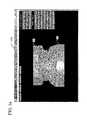
- FIG. 1 aillustrates an example embodiment of an electronic model for an upper and lower jaw impression electronically interacting with each other according to one possible embodiment of the present invention.
- FIG. 1 billustrates an example embodiment of an electronic model of a dental impression used to demonstrate articulation of a jaw and corresponding teeth according to one possible embodiment of the present invention.
- FIG. 2illustrates another example embodiment of an electronic model for an upper and lower jaw impression electronically interacting with each other according to one possible embodiment of the present invention.
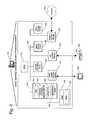
- FIG. 3illustrates a computing system that may be used to construct various computing systems that may be part of a distributed processing and communications system according to one embodiment of the present invention.
- FIG. 4illustrates a lower jaw dental impression physical model scanning plate apparatus according to an example embodiment of the present invention.
- FIG. 5illustrates an upper and a lower jaw dental impression physical model scanning plate apparatus according to an example embodiment of the present invention.
- FIG. 6illustrates a spatial transformation for a point located on an upper electronic model from its own coordinate system to a single coordinate system.
- FIG. 7illustrates an exploded view for the upper and lower jaw dental impression physical model scanning plate apparatus according to an example embodiment of the present invention.
- FIG. 8illustrates a set of processing modules used within a processing system that is part of a system for generating an electronic model for dental impression having a common coordinate system according to another example embodiment of the present invention.
- FIG. 9illustrates an example operation flow for a system for generating an electronic model for a dental impression having a common coordinate system according to one possible embodiment of the present invention.
- FIG. 10illustrates a schematic system in which the approximate location of the registration/alignment spheres can be determined by finding two edge points (E 1 and E 2 ).
- connectionmeans a direct connection between the items connected, without any intermediate devices.
- coupledmeans either a direct connection between the items connected, or an indirect connection through one or more passive or active intermediary devices.
- circuitmeans either a single component or a multiplicity of components, either active and/or passive, that are coupled together to provide a desired function.
- signalmeans at least one current, voltage, or data signal.
- FIG. 1 aillustrates an example embodiment of an electronic model for an upper and lower jaw impression electronically interacting with each other according to one possible embodiment of the present invention.
- a computer-generated image 100 of a pair of electronic models corresponding to a patient's upper jaw 101 and lower jaw 102are shown. These two models are generated separately and then positioned together to allow the interaction of the opposing teeth present in the upper jaw 101 and the lower jaw 102 electronic models. This interaction of the upper jaw 101 and the lower jaw 102 cannot occur until the coordinate systems of the two electronic models are combined into a single coordinate system.
- FIG. 1 billustrates an example embodiment of an electronic model of a dental impression used to demonstrate articulation of a jaw and corresponding teeth according to one possible embodiment of the present invention.
- the electronic models for the upper jaw 101 and the lower jaw 102are super imposed upon an x-ray of the patient's skull 120 to allow the two electronic models to be moved relative to each other about a point of rotation for the jaw 121 in a manner that is consistent with the actual geometry of a patient as shown in the x-ray 120 .
- This movement and interaction of the upper jaw 101 and the lower jaw 102also require the use of a common coordinate system for the electronic models for the upper jaw 101 and the lower jaw 102 .
- FIG. 2illustrates another example embodiment of an electronic model for an upper and lower jaw impression electronically interacting with each other according to one possible embodiment of the present invention.
- the upper jaw 101 and the lower jaw 102are shown in a position that corresponds to the position in which the two physical models may be scanned together.
- the two modelsare shown with a flat surface of the base elements in which the impressions for the teeth are mounted.
- the two flat surfacesare typically shown in a co-planar arrangement with some physical separation for the two models.
- the side surfaces of the base elementscontain a few co-planar surfaces that allow the registration of the models in various dimensions, the vertical Z-axis for the two models is not radially detectable. As such, additional steps must be taken to translate the positions in the two electronic models into a single coordinate system. These operations must occur before the two models 101 - 102 may be manipulated as opposing teeth and jaws.
- FIG. 3illustrates a computing system that may be used to construct various computing systems that may be part of a distributed processing and communications system according to one embodiment of the present invention.
- computing system 301is operative to provide a dental scanning coordinate processing system.
- the dental scanning coordinate processing system 301may include many more components than those shown with reference to a computing system 301 shown in FIG. 3 . However, the components shown are sufficient to disclose an illustrative embodiment for practicing the present invention.
- a network interface unit 310includes the necessary circuitry for connecting dental scanning coordinate system processing system 301 to a network of other computing systems 305 , and is constructed for use with various communication protocols including the TCP/IP protocol.
- network interface unit 310is a card contained within neural network training and data collection system.
- Dental scanning coordinate system processing system 301also includes processing unit 312 , video display adapter 314 , and a mass memory 316 , all connected via bus 322 .
- the mass memorygenerally includes RAM 416 , ROM 432 , and one or more permanent mass storage devices, such as hard disk drive 328 , a tape drive, CD-ROM/DVD-ROM drive 326 , and/or a floppy disk drive.
- the mass memorystores operating system 320 for controlling the operation of dental scanning coordinate processing system 301 . It will be appreciated that this component may comprise a general purpose server operating system as is known to those of ordinary skill in the art, such as UNIX, MAC OSTM, LINUXTM, OR Microsoft WINDOWS NT®.
- BIOSBasic input/output system
- Computer storage mediamay include volatile and nonvolatile, removable and non-removable media implemented in any method or technology for storage of information, such as computer readable instructions, data structures, program modules or other data.
- Examples of computer storage mediainclude RAM, ROM, EEPROM, flash memory or other memory technology, CD-ROM, digital versatile disks (DVD) or other optical storage, magnetic cassettes, magnetic tape, magnetic disk storage or other magnetic storage devices, or any other medium which can be used to store the desired information and which can be accessed by a computing device.
- the mass memoryalso stores program code and data for providing a software development and neural network analysis and training system. More specifically, the mass memory stores applications including common coordinate system application program 330 , programs 343 , and similar data processing applications 336 .
- Common coordinate system application program 330includes computer executable instructions which, when executed by computer 301 to perform the logic desired herein.
- Dental scanning coordinate system processing system 301also comprises input/output interface 324 for communicating with external devices, such as a mouse 304 , keyboard 303 , scanner, or other input devices not shown in FIG. 3 .
- a dental scanning coordinate system processing system 301may further comprise additional mass storage facilities such as CD-ROM/DVD-ROM drive 326 and hard disk drive 328 .
- Hard disk drive 328is utilized by Dental scanning coordinate system processing system 301 to store, among other things, application programs, databases, and program data used by common coordinate system application program 330 .
- FIG. 4illustrates a lower jaw dental impression physical model scanning apparatus according to an example embodiment of the present invention.
- the apparatus 400is used to scan a physical impression model for a jaw.
- a lower jaw 102 physical modelis shown.
- the apparatuscomprises a scanning base plate module 401 and a physical model plate module 402 .
- the scanning base plate module 401is mounted onto a scanning device such that a model that is scanned while attached to the apparatus 400 is located within a known location of the scanning system coordinate system.
- the scanning systemis calibrated to know the position of the scanning base plate 401 .
- the scanning base plate module 401contains an x-axis alignment channel 411 and a y-axis alignment channel 410 .
- These two alignment channelsare located on the scanning base plate module 401 in a perpendicular and a co-planar within the plane defined by the top surface of the scanning base plate module 401 .
- These two alignment channelsare generally v-shaped such that the vertex of the channel defines the deepest point within the channel.
- the physical model plate module 402comprises a y-axis channel alignment sphere 421 , a first x-axis channel alignment sphere 422 , and a second x-axis channel alignment sphere 423 .
- the physical model plate module 402also comprises a set of physical model attachment devices 431 - 433 that are used to secure the physical model 102 into a fixed position on the physical model plate module 402 .
- the y-axis channel alignment sphere 421 , the first x-axis channel alignment sphere 422 , and the second x-axis channel alignment sphere 423are defined by a radius corresponding to the size of the two alignment channels within the scanning base plate module 401 .
- These three spheresengage the two alignment channel to position the physical model plate module 402 at a known and repeatable position relative to the scanning base plate model 401 .
- a scan of a physical model 102will be at a known position relative to the scanning device.
- This aligned positionoccurs because the first x-axis channel alignment sphere 422 and the second x-axis channel alignment sphere 423 position the physical module plate module 402 at a known position relative to the scanning base plate module 401 in the x-axis dimension.
- the y-axis channel alignment sphere 421engaging the y-axis alignment channel 410 to position the physical module plate module 402 at a known position relative to the scanning base plate module 401 in the y-axis dimension.
- the combination of the two alignment channels 410 - 411 and the three alignment spheres 421 - 423allows the physical model plate module 402 to be located at a single position within a plate parallel to the top of the scanning plate module 401 .
- FIG. 5illustrates an upper and lower jaw dental impression physical model scanning plate apparatus according to an example embodiment of the present invention.
- the physical model scanning apparatus 400 discussed in reference to FIG. 4is shown.
- a second physical model scanning apparatus 500 that contains the opposing physical model for an upper jaw 101is also shown.
- the second physical model scanning apparatus 500operates identically to the apparatus 400 discussed in reference to FIG. 4 for a second physical model.
- each apparatus 400 , 500also contain an articulation member 531 , 532 . These two articulation members are coupled together to position the upper apparatus 500 at a position relative to the lower apparatus 400 that simulates the interaction of the upper jaw physical model 101 and the lower jaw physical model 102 .
- the two physical models 101 , 102may be positioned into any desired position relative to each other.
- the desired positionmay be defined by a user who moved the two apparatus 400 , 500 until the two jaw models are in the desired position relative to each other.
- additional itemssuch as a bite wax impression obtained from the patient may be inserted between the two physical models to position them in a desired position corresponding to the geometry of the patient's mouth.
- centric, occlusion centric relation, protrusive, and lateral excursionmight be used to determine jaw motion.
- the systemcould manipulate the jaw image between established positions to obtain an electronic simulation of jaw motion (e.g., digital articulation).
- the combined apparatusmay be scanned while attached to the scanning device within the coordinate system used in generating the electronic model 102 for the lower jaw to determine the position of the upper apparatus 500 within the same coordinate system.
- the scanningis performed for the combined apparatus, only the location of one of the alignment spheres 521 - 523 need to be determined. From this additional information, the location of any point on the electronic model 101 for the upper jaw may be expressed in terms of the coordinate system used to define the electrode model 102 for the lower jaw. This coordinate transformation is illustrated in reference to FIG. 6 below.
- FIG. 6illustrates a spatial transformation for a point located on an upper electronic model from its own coordinate system to a single coordinate system.
- a point Pi 601 on the electronic model for the upper jaw 101is defined in terms of a common coordinate system having an origin O.
- Vk 611is defined in terms of the coordinate system used when the electronic model for the upper jaw was scanned. This vector is known since both the point Pi 601 is known in the coordinate system used when the electronic model for the upper jaw was scanned and the point Pj 602 is known as the top point on the sphere 521 in the same coordinate system. This point is known as a fixed point in the coordinate system when the alignment spheres are engaged with the alignment channels.
- Vector Vj 612is the value for the location of this top point on sphere 521 when the combined apparatus is scanned after the two physical models are moved into the desired position. These two vectors, when added together for each location on the upper electronic model 101 , transforms all of the coordinates from the two separate coordinate systems into a single coordinate system.
- FIG. 7illustrates an exploded view for the upper and lower jaw dental impression physical model scanning plate apparatus according to an example embodiment of the present invention.
- the exploded viewincludes the scanning base plate module 401 corresponding to the electronic model generated for the lower jaw model 102 ; the physical model plate module 402 including its three alignment spheres 421 - 423 , and the physical module corresponding to the lower jaw 102 .
- the exploded view of FIG. 7also includes the physical model corresponding to the upper jaw 101 and the physical model plate module 501 including its three alignment spheres 521 - 523 used to generate the electronic model for the upper jaw 101 .
- These componentswork together as discussed above to generate a composite electronic model for the upper and low jaw of a patient within a common coordinate system.
- FIG. 8illustrates a set of processing modules used within processing system that is part of a system for generating an electronic model for a dental impression having a common coordinate system according to another example embodiment of the present invention.
- a dental scanning common coordinate system processing system 801comprises a set of data processing modules that are used to generate the separate upper and low jaw electronic models and combine the data from these two models into a common coordinate system.
- the dental scanning common coordinate system processing system 801includes a physical model scanning module 811 , a physical model reference point determination module 812 , and an electronic model coordinate system transformation module 813 .
- the dental scanning common coordinate system processing system 801also includes a electronic model database 802 for storing and retrieving electronic model data as needed from data storage. In most embodiments, the database is maintained within mass storage devices attached to a programmable processing system.
- the physical model scanning module 811interacts with a laser scanning device to obtain a set of position data points obtained from the scanning of a physical model.
- This processing system 801performs all of the processing necessary to reduce this data of location points to an electronic model defined in a polygonal mesh.
- These electronic models generated by this processing module 801may be stored within the electronic model database 802 for later use. These electronic models may also be passed to the physical model reference point determination module 812 , for further processing.
- the physical model reference point determination module 812interacts with the laser scanning device to obtain the location of the reference data point Pj 602 as discussed above with respect to FIG. 6 on a composite apparatus.
- This reference data point Pj 602is used to generate the transformation vector Vj 612 that is used to generate the transformed location data when location data points from an upper jaw electronic model are processed to express location information within a common coordinate system.
- the electronic model coordinate system transformation module 813uses the vector Vj 612 determined within the physical model reference point determination module 812 to generate the coordinate data values for each point in an electronic model of an upper jaw 101 within the common coordinate system. This module 813 may be used to transform every data point within an electronic model before the updated electronic model is stored in the electronic model database 802 . Alternatively, this module 813 may be used to transform the data points within an area/region of interest in the electronic model to allow the process to be completed more quickly.
- One skilled in the artwill recognize that many different processing mechanisms for generating and applying the transformation vector Vj 612 without deviating from the spirit and scope of the present invention as recited within the attached claims.
- FIG. 9illustrates an example operation flow for a system for generating an electronic model for a dental impression having a common coordinate system according to one possible embodiment of the present invention.
- the processbegins 901 and proceeds to operation 911 in which the various physical models are mounted on the scanning apparatus that is part of a scanning device.
- the physical modelsare located within the coordinate system of the scanning device for scanning.
- operation 912scans the physical models and then generates the electronic models corresponding to the various physical models.
- These electronic modelsare expressed as a polygonal mesh that corresponds to the outside surface of the physical objects.
- Operation 913positions the various physical models into desired positions in which the physical models interact with each other in the same way that the corresponding physical objects interact with each other.
- the upper and lower physical modelsare positioned into a position that represents the relationship of the upper and lower jaw of a patient. This positioning may occur in different ways as discussed above with reference to FIG. 6 without deviating from the spirit and scope of the present invention as recited in the attached claims.
- operation 914scans one or more reference points on the combined scanning apparatus.
- This scanningmay include the scanning of the alignment spheres on a physical model plate module 502 for an upper object to obtain a point of known position on the upper electronic model that is also known within the coordinate system for the upper object when it was scanned individually.
- This reference point location datais then used to define a transformation vector Vj as discussed above.
- operation 915uses the vector Vj to transform the position location information within the electronic model of the upper object into corresponding position locations within a common coordinate system with the physical objects positioned at a desired location.
- FIG. 10Another feature of the present invention is illustrated in FIG. 10 .
- the systemmay employ an algorithm to locate two edge points E 1 and E 2 of the physical model plate module 402 . By locating these edge points and recalling the geometry between the edge points, then the first sphere A can be found. The second and third sphere's B and C can then subsequently be found.
- the scannerfirst finds the surface of the physical model plate module 402 and then begins scanning along a first scan line designated at 1001 . Once the scanner locates the edge point E 1 , the scanner steps over and performs a second scan along a second scan line designated at 1002 . The scan system stores the distance x between the two scan lines 1001 and 1002 . Once the second edge point E 2 is located, a vector E 1 E 2 is determined and the scanner is able to rapidly move along the vector until it comes to the edge of sphere A. At this time, sphere A is scanned in detail and the location of sphere A is computed. Once vector E 1 E 2 is known and the location of A is known in detail, then spheres B and C can be located more rapidly.
- FIG. 3illustrates an example of a suitable operating environment in which the invention may be implemented.
- the operation environmentis only one example of a suitable operating environment and is not intended to suggest any limitation s to the scope of use or functionality of the invention.
- Other well known computing systems, environments, and/or configurationsthat may be suitable for use with the invention include, but are not limited to, personal computers, server computers, held-held or laptop devices, multiprocessor systems, microprocessor-based systems, programmable consumer electronics, network PCs, minicomputers, mainframe computers, distributed computing environments that include any of the above systems or devices, and the like.
- program modulesinclude routines, programs, objects, components, data structures, etc. that perform particular tasks or implement particular abstract data types.
- functionality of the program modulesmay be combined or distributed in desired various embodiments.
- a processing device attached to a communications networktypically includes at least some form of computer readable media.
- Computer readable mediacan be any available media that can be accessed by these devices.
- Computer readable mediamay comprise computer storage media and communication media.
- Computer storage mediaincludes volatile and non-volatile, removable and non-removable media implemented in any method or technology for storage of information such as computer readable instructions, data structures, program modules or other data.
- Computer storage mediaincludes, but is not limited to, RAM, ROM, EEPROM, flash memory or other memory technology, CD-ROM, digital versatile disks (DVD) or other optical storage, magnetic cassettes, magnetic tape, magnetic disk storage or other magnetic storage devices, or any other medium which can be used to store the desired information and which can be accessed by process devices.
- Communication mediatypically embodies computer readable instructions, data structure, program modules or other data in a modulated data signal such as a carrier wave or other transport mechanism and includes any information delivery media.
- modulated data signalmeans a signal that has one or more of its characteristics set or changed in such a manner as to encode information in a signal.
- communication mediaincludes wired media such as a wired network or direct-wired connection, and wireless media such as an acoustic, RF, infrared and other wireless media. Combinations of any of the above should also be included within the scope of computer readable media.
- the embodiments described hereinare implemented as a logical operation performed by a programmable processing device.
- the logical operation of these various embodiments of the present inventionare implemented (1) as a sequence of computer implemented steps or program modules running on a computing system and/or (2) as interconnected machine modules or hardware logic within the computing system.
- the implementationis a matter of choice dependent on the performance requirements of the computing system implementing the invention. Accordingly, the logical operations making up the embodiments of the invention described herein can be variously referred to as operations, steps, or modules.
Landscapes
- Health & Medical Sciences (AREA)
- Engineering & Computer Science (AREA)
- Physics & Mathematics (AREA)
- Oral & Maxillofacial Surgery (AREA)
- Epidemiology (AREA)
- General Physics & Mathematics (AREA)
- Theoretical Computer Science (AREA)
- Geometry (AREA)
- Computer Graphics (AREA)
- Dentistry (AREA)
- Software Systems (AREA)
- Life Sciences & Earth Sciences (AREA)
- Animal Behavior & Ethology (AREA)
- General Health & Medical Sciences (AREA)
- Public Health (AREA)
- Veterinary Medicine (AREA)
- Dental Tools And Instruments Or Auxiliary Dental Instruments (AREA)
Abstract
Description
Claims (17)
Priority Applications (1)
| Application Number | Priority Date | Filing Date | Title |
|---|---|---|---|
| US12/715,999US8417493B2 (en) | 2004-03-11 | 2010-03-02 | Scanning dental models |
Applications Claiming Priority (2)
| Application Number | Priority Date | Filing Date | Title |
|---|---|---|---|
| US10/799,344US7702492B2 (en) | 2004-03-11 | 2004-03-11 | System and method for generating an electronic model for a dental impression having a common coordinate system |
| US12/715,999US8417493B2 (en) | 2004-03-11 | 2010-03-02 | Scanning dental models |
Related Parent Applications (1)
| Application Number | Title | Priority Date | Filing Date |
|---|---|---|---|
| US10/799,344ContinuationUS7702492B2 (en) | 2004-03-11 | 2004-03-11 | System and method for generating an electronic model for a dental impression having a common coordinate system |
Publications (2)
| Publication Number | Publication Date |
|---|---|
| US20100217567A1 US20100217567A1 (en) | 2010-08-26 |
| US8417493B2true US8417493B2 (en) | 2013-04-09 |
Family
ID=34920492
Family Applications (2)
| Application Number | Title | Priority Date | Filing Date |
|---|---|---|---|
| US10/799,344Active2026-01-11US7702492B2 (en) | 2004-03-11 | 2004-03-11 | System and method for generating an electronic model for a dental impression having a common coordinate system |
| US12/715,999Expired - Fee RelatedUS8417493B2 (en) | 2004-03-11 | 2010-03-02 | Scanning dental models |
Family Applications Before (1)
| Application Number | Title | Priority Date | Filing Date |
|---|---|---|---|
| US10/799,344Active2026-01-11US7702492B2 (en) | 2004-03-11 | 2004-03-11 | System and method for generating an electronic model for a dental impression having a common coordinate system |
Country Status (1)
| Country | Link |
|---|---|
| US (2) | US7702492B2 (en) |
Families Citing this family (35)
| Publication number | Priority date | Publication date | Assignee | Title |
|---|---|---|---|---|
| SE527666C2 (en)* | 2004-09-30 | 2006-05-02 | Nobel Biocare Ab | Scanner device |
| BRPI0720906B8 (en)* | 2007-01-10 | 2021-06-22 | Nobel Biocare Services Ag | method and system for planning a dental restorative procedure and computer system for carrying out the method |
| GB0706048D0 (en)* | 2007-03-28 | 2007-05-09 | Unilever Plc | A method and apparatus for generating a model of an object |
| US20090081617A1 (en)* | 2007-09-21 | 2009-03-26 | D4D Technologies, Llc | Display interface target positioning tool |
| JP5250251B2 (en)* | 2007-12-17 | 2013-07-31 | イマグノーシス株式会社 | Medical imaging marker and its utilization program |
| WO2009105193A1 (en)* | 2008-02-21 | 2009-08-27 | Van Valey Edwin T | Improved dental model baseplate |
| DE102010000451A1 (en)* | 2010-02-17 | 2011-08-18 | Amann Girrbach Ag | Digital three-dimensional data model creating method for upper and lower jaws of patient, involves creating model by arrangement of upper and lower jaw data models relative to each other in bite layer or by association of detected marks |
| US8905757B2 (en) | 2012-12-03 | 2014-12-09 | E. Kats Enterprises Ltd. | Method and apparatus for measuring a location and orientation of a plurality of implants |
| US9545296B2 (en) | 2013-08-05 | 2017-01-17 | Stephen R Hansen | Digital face bow system and method |
| WO2016030754A1 (en)* | 2014-08-29 | 2016-03-03 | Trophy | Method and apparatus for dental virtual model base |
| US9629698B2 (en) | 2014-11-04 | 2017-04-25 | James R. Glidewell Dental Ceramics, Inc. | Method and apparatus for generation of 3D models with applications in dental restoration design |
| AU2017268703B2 (en)* | 2016-05-23 | 2018-12-13 | Jessi Lew Pty Limited | Methods and apparatus for digital imaging of dental models |
| WO2018022752A1 (en)* | 2016-07-27 | 2018-02-01 | James R. Glidewell Dental Ceramics, Inc. | Dental cad automation using deep learning |
| US11559378B2 (en) | 2016-11-17 | 2023-01-24 | James R. Glidewell Dental Ceramics, Inc. | Scanning dental impressions |
| US11270523B2 (en) | 2017-11-29 | 2022-03-08 | Sdc U.S. Smilepay Spv | Systems and methods for constructing a three-dimensional model from two-dimensional images |
| US10109114B1 (en)* | 2017-11-29 | 2018-10-23 | SmileDirectClub LLC | Technologies for merging three-dimensional models of dental impressions |
| US10410435B2 (en) | 2017-11-29 | 2019-09-10 | SmileDirectClub LLC | Technologies for merging three-dimensional models of dental impressions |
| US10861250B2 (en) | 2017-11-29 | 2020-12-08 | Sdc U.S. Smilepay Spv | Technologies for merging three-dimensional models of dental impressions |
| US11403813B2 (en) | 2019-11-26 | 2022-08-02 | Sdc U.S. Smilepay Spv | Systems and methods for constructing a three-dimensional model from two-dimensional images |
| US11007040B2 (en) | 2018-03-19 | 2021-05-18 | James R. Glidewell Dental Ceramics, Inc. | Dental CAD automation using deep learning |
| US11049606B2 (en) | 2018-04-25 | 2021-06-29 | Sota Precision Optics, Inc. | Dental imaging system utilizing artificial intelligence |
| EP3591616A1 (en)* | 2018-07-03 | 2020-01-08 | Promaton Holding B.V. | Automated determination of a canonical pose of a 3d dental structure and superimposition of 3d dental structures using deep learning |
| US10839481B1 (en)* | 2018-12-07 | 2020-11-17 | Bellus 3D, Inc. | Automatic marker-less alignment of digital 3D face and jaw models |
| US10810738B1 (en)* | 2018-12-07 | 2020-10-20 | Bellus 3D, Inc. | Marker-less alignment of digital 3D face and jaw models |
| US11030801B2 (en) | 2019-05-17 | 2021-06-08 | Standard Cyborg, Inc. | Three-dimensional modeling toolkit |
| US12056820B2 (en) | 2019-05-17 | 2024-08-06 | Sdc U.S. Smilepay Spv | Three-dimensional modeling toolkit |
| US11534271B2 (en) | 2019-06-25 | 2022-12-27 | James R. Glidewell Dental Ceramics, Inc. | Processing CT scan of dental impression |
| US11622843B2 (en) | 2019-06-25 | 2023-04-11 | James R. Glidewell Dental Ceramics, Inc. | Processing digital dental impression |
| US11540906B2 (en) | 2019-06-25 | 2023-01-03 | James R. Glidewell Dental Ceramics, Inc. | Processing digital dental impression |
| US11842484B2 (en) | 2021-01-04 | 2023-12-12 | James R. Glidewell Dental Ceramics, Inc. | Teeth segmentation using neural networks |
| US11544846B2 (en) | 2020-08-27 | 2023-01-03 | James R. Glidewell Dental Ceramics, Inc. | Out-of-view CT scan detection |
| CA3152850A1 (en) | 2021-03-23 | 2022-09-23 | Tactile Robotics Ltd. | Automated measurement apparatus and method for quantifying dimensions of dental preparation |
| US12136208B2 (en) | 2021-03-31 | 2024-11-05 | James R. Glidewell Dental Ceramics, Inc. | Automatic clean up of jaw scans |
| US12210802B2 (en) | 2021-04-30 | 2025-01-28 | James R. Glidewell Dental Ceramics, Inc. | Neural network margin proposal |
| US12295806B2 (en) | 2022-01-10 | 2025-05-13 | James R. Glidewell Dental Ceramics, Inc. | Automatic determination of trim-line for aligners |
Citations (106)
| Publication number | Priority date | Publication date | Assignee | Title |
|---|---|---|---|---|
| US3084438A (en) | 1959-08-24 | 1963-04-09 | David J Goodfriend | Dental method and apparatus |
| US4123786A (en) | 1976-07-07 | 1978-10-31 | U.S. Philips Corporation | X-ray examining device comprising a television chain which includes a memory |
| US4123768A (en) | 1977-03-09 | 1978-10-31 | Victoria University Of Manchester | Method and apparatus for photographically recording three-dimensional models of dental arch profiles |
| US4182312A (en) | 1977-05-20 | 1980-01-08 | Mushabac David R | Dental probe |
| US4402326A (en) | 1980-05-02 | 1983-09-06 | Kabushiki Kaisha Morita Seisakusho | Occlusion pressure image system |
| US4436684A (en) | 1982-06-03 | 1984-03-13 | Contour Med Partners, Ltd. | Method of forming implantable prostheses for reconstructive surgery |
| US4575805A (en) | 1980-12-24 | 1986-03-11 | Moermann Werner H | Method and apparatus for the fabrication of custom-shaped implants |
| US4611288A (en) | 1982-04-14 | 1986-09-09 | Francois Duret | Apparatus for taking odontological or medical impressions |
| US4673352A (en) | 1985-01-10 | 1987-06-16 | Markus Hansen | Device for measuring relative jaw positions and movements |
| US4742464A (en) | 1983-04-14 | 1988-05-03 | Francois Duret | Method of making a prosthesis, especially a dental prosthesis |
| US4752964A (en) | 1984-04-17 | 1988-06-21 | Kawasaki Jukogyo Kabushiki Kaisha | Method and apparatus for producing three-dimensional shape |
| US4775946A (en) | 1985-03-29 | 1988-10-04 | Hitachi, Ltd. | Method for constructing three-dimensional polyhedron model |
| US4799785A (en) | 1986-10-17 | 1989-01-24 | Keates Richard H | Cornea contour mapping |
| US4837732A (en) | 1986-06-24 | 1989-06-06 | Marco Brandestini | Method and apparatus for the three-dimensional registration and display of prepared teeth |
| US4862371A (en) | 1986-08-18 | 1989-08-29 | Mitsubishi Denki Kabushiki Kaisha | Fault diagnosis system for electronic devices on automobiles |
| US4862391A (en) | 1986-09-29 | 1989-08-29 | Kabushiki Kaisha Toshiba | Shading circuit for shading a plurality of polygons which constitute a solid model, and method of shading the same |
| US4935635A (en) | 1988-12-09 | 1990-06-19 | Harra Dale G O | System for measuring objects in three dimensions |
| US4983120A (en) | 1988-05-12 | 1991-01-08 | Specialty Appliance Works, Inc. | Method and apparatus for constructing an orthodontic appliance |
| US5020993A (en) | 1990-01-02 | 1991-06-04 | Levandoski Ronald R | Dental articulator |
| US5027281A (en) | 1989-06-09 | 1991-06-25 | Regents Of The University Of Minnesota | Method and apparatus for scanning and recording of coordinates describing three dimensional objects of complex and unique geometry |
| US5113424A (en) | 1991-02-04 | 1992-05-12 | University Of Medicine & Dentistry Of New Jersey | Apparatus for taking radiographs used in performing dental subtraction radiography with a sensorized dental mouthpiece and a robotic system |
| US5121333A (en) | 1989-06-09 | 1992-06-09 | Regents Of The University Of Minnesota | Method and apparatus for manipulating computer-based representations of objects of complex and unique geometry |
| US5150457A (en) | 1990-05-02 | 1992-09-22 | International Business Machines Corporation | Enhanced visualization using translucent contour surfaces |
| US5184306A (en) | 1989-06-09 | 1993-02-02 | Regents Of The University Of Minnesota | Automated high-precision fabrication of objects of complex and unique geometry |
| US5198827A (en) | 1991-05-23 | 1993-03-30 | Hughes Aircraft Company | Dual reflector scanning antenna system |
| US5198877A (en) | 1990-10-15 | 1993-03-30 | Pixsys, Inc. | Method and apparatus for three-dimensional non-contact shape sensing |
| US5224049A (en) | 1990-04-10 | 1993-06-29 | Mushabac David R | Method, system and mold assembly for use in preparing a dental prosthesis |
| US5257184A (en) | 1990-04-10 | 1993-10-26 | Mushabac David R | Method and apparatus with multiple data input stylii for collecting curvilinear contour data |
| US5257203A (en) | 1989-06-09 | 1993-10-26 | Regents Of The University Of Minnesota | Method and apparatus for manipulating computer-based representations of objects of complex and unique geometry |
| US5267293A (en) | 1991-05-06 | 1993-11-30 | Planmeca Oy | Method and apparatus for panoramic radiogragraphy |
| US5273429A (en) | 1992-04-03 | 1993-12-28 | Foster-Miller, Inc. | Method and apparatus for modeling a dental prosthesis |
| US5320528A (en) | 1991-02-05 | 1994-06-14 | Alpern Michael C | Dental articulator |
| US5338198A (en) | 1993-11-22 | 1994-08-16 | Dacim Laboratory Inc. | Dental modeling simulator |
| US5340309A (en) | 1990-09-06 | 1994-08-23 | Robertson James G | Apparatus and method for recording jaw motion |
| US5343391A (en) | 1990-04-10 | 1994-08-30 | Mushabac David R | Device for obtaining three dimensional contour data and for operating on a patient and related method |
| US5347454A (en) | 1990-04-10 | 1994-09-13 | Mushabac David R | Method, system and mold assembly for use in preparing a dental restoration |
| US5359511A (en) | 1992-04-03 | 1994-10-25 | Foster-Miller, Inc. | Method and apparatus for obtaining coordinates describing three-dimensional objects of complex and unique geometry using a sampling probe |
| US5368478A (en) | 1990-01-19 | 1994-11-29 | Ormco Corporation | Method for forming jigs for custom placement of orthodontic appliances on teeth |
| US5372502A (en) | 1988-09-02 | 1994-12-13 | Kaltenbach & Voight Gmbh & Co. | Optical probe and method for the three-dimensional surveying of teeth |
| US5395238A (en) | 1990-01-19 | 1995-03-07 | Ormco Corporation | Method of forming orthodontic brace |
| US5416822A (en) | 1994-08-29 | 1995-05-16 | Kunik; Randall L. | Device for registering a dental radiograph having distortion measuring capability and method for using the same |
| US5431562A (en) | 1990-01-19 | 1995-07-11 | Ormco Corporation | Method and apparatus for designing and forming a custom orthodontic appliance and for the straightening of teeth therewith |
| US5440393A (en) | 1990-03-13 | 1995-08-08 | Com Dent Gmbh | Process and device for measuring the dimensions of a space, in particular a buccal cavity |
| US5442572A (en) | 1992-11-23 | 1995-08-15 | Ford Motor Company | Method and system for comparing free-form geometries using high density point data models |
| US5447432A (en) | 1990-01-19 | 1995-09-05 | Ormco Corporation | Custom orthodontic archwire forming method and apparatus |
| US5448472A (en) | 1990-04-10 | 1995-09-05 | Mushabac; David R. | Method using reference indicia on tape attached to mouth surface to obtain three dimensional contour data |
| US5454068A (en) | 1991-02-25 | 1995-09-26 | International Business Machines Corporation | Scientific visualization system |
| US5454717A (en) | 1990-01-19 | 1995-10-03 | Ormco Corporation | Custom orthodontic brackets and bracket forming method and apparatus |
| US5458487A (en) | 1992-10-15 | 1995-10-17 | Fuji Photo Film Co., Ltd. | System for analyzing occlusion condition |
| USRE35169E (en) | 1989-01-24 | 1996-03-05 | Ormco Corporation | Method for determining orthodontic bracket placement |
| US5518397A (en) | 1990-01-19 | 1996-05-21 | Ormco Corporation | Method of forming an orthodontic brace |
| US5533895A (en) | 1990-01-19 | 1996-07-09 | Ormco Corporation | Orthodontic appliance and group standardized brackets therefor and methods of making, assembling and using appliance to straighten teeth |
| US5549476A (en) | 1995-03-27 | 1996-08-27 | Stern; Sylvan S. | Method for making dental restorations and the dental restoration made thereby |
| US5562448A (en) | 1990-04-10 | 1996-10-08 | Mushabac; David R. | Method for facilitating dental diagnosis and treatment |
| US5588430A (en) | 1995-02-14 | 1996-12-31 | University Of Florida Research Foundation, Inc. | Repeat fixation for frameless stereotactic procedure |
| US5605459A (en) | 1995-04-14 | 1997-02-25 | Unisn Incorporated | Method of and apparatus for making a dental set-up model |
| US5683243A (en) | 1992-11-09 | 1997-11-04 | Ormco Corporation | Custom orthodontic appliance forming apparatus |
| US5730151A (en) | 1995-06-30 | 1998-03-24 | John D. Summer | Tooth contact sensing apparatus and method |
| WO1998032394A1 (en) | 1997-01-28 | 1998-07-30 | Bruce Willard Hultgren | Dental scanning method and apparatus |
| US5800174A (en) | 1994-02-18 | 1998-09-01 | Nobel Biocare Ab | Method using an articulator and computer to represent an individual's bite |
| US5823778A (en) | 1996-06-14 | 1998-10-20 | The United States Of America As Represented By The Secretary Of The Air Force | Imaging method for fabricating dental devices |
| US5842858A (en) | 1995-05-11 | 1998-12-01 | Artma Biomedical, Inc. | Method of imaging a person's jaw and a model therefor |
| US5879158A (en) | 1997-05-20 | 1999-03-09 | Doyle; Walter A. | Orthodontic bracketing system and method therefor |
| US5880962A (en) | 1993-07-12 | 1999-03-09 | Nobel Biocare Ab | Computer aided processing of three-dimensional object and apparatus thereof |
| US5882192A (en) | 1997-10-30 | 1999-03-16 | Ortho-Tain, Inc. | Computerized orthodontic diagnosis and appliance dispenser |
| US5905658A (en) | 1996-03-07 | 1999-05-18 | Nikon Corporation | Simulation method and apparatus of jaw movement |
| US5977979A (en) | 1995-10-31 | 1999-11-02 | International Business Machines Corporation | Simulated three-dimensional display using bit-mapped information |
| US5989199A (en) | 1996-11-27 | 1999-11-23 | Assurance Medical, Inc. | Tissue examination |
| US6068482A (en) | 1996-10-04 | 2000-05-30 | Snow; Michael Desmond | Method for creation and utilization of individualized 3-dimensional teeth models |
| US6123544A (en) | 1998-12-18 | 2000-09-26 | 3M Innovative Properties Company | Method and apparatus for precise bond placement of orthodontic appliances |
| US6143003A (en) | 1995-01-31 | 2000-11-07 | Cosman; Eric R. | Repositioner for head, neck, and body |
| US6152731A (en) | 1997-09-22 | 2000-11-28 | 3M Innovative Properties Company | Methods for use in dental articulation |
| US6227850B1 (en) | 1999-05-13 | 2001-05-08 | Align Technology, Inc. | Teeth viewing system |
| US20010002310A1 (en) | 1997-06-20 | 2001-05-31 | Align Technology, Inc. | Clinician review of an orthodontic treatment plan and appliance |
| US6250918B1 (en) | 1999-11-30 | 2001-06-26 | Orametrix, Inc. | Method and apparatus for simulating tooth movement for an orthodontic patient |
| US6318994B1 (en) | 1999-05-13 | 2001-11-20 | Align Technology, Inc | Tooth path treatment plan |
| US6322728B1 (en) | 1998-07-10 | 2001-11-27 | Jeneric/Pentron, Inc. | Mass production of dental restorations by solid free-form fabrication methods |
| US6334853B1 (en) | 1997-05-22 | 2002-01-01 | Cadent Ltd | Method for obtaining a dental occlusion map |
| US20020015934A1 (en) | 1999-11-30 | 2002-02-07 | Rudger Rubbert | Interactive orthodontic care system based on intra-oral scanning of teeth |
| US20020031743A1 (en) | 1999-04-07 | 2002-03-14 | Nu-Tek Dental, Llc. | Dental articulator |
| US6364660B1 (en) | 2000-10-25 | 2002-04-02 | Duane Milford Durbin | Method and system for imaging and modeling dental structures |
| US6371761B1 (en) | 2000-03-30 | 2002-04-16 | Align Technology, Inc. | Flexible plane for separating teeth models |
| US6406292B1 (en) | 1999-05-13 | 2002-06-18 | Align Technology, Inc. | System for determining final position of teeth |
| US6409504B1 (en) | 1997-06-20 | 2002-06-25 | Align Technology, Inc. | Manipulating a digital dentition model to form models of individual dentition components |
| US20020081554A1 (en) | 2000-12-22 | 2002-06-27 | Marshall Michael C. | Mating parts scanning and registration methods |
| US6436684B1 (en) | 2000-03-27 | 2002-08-20 | Applera Corporation | Isolated human drug-metabolizing proteins, nucleic acid molecules encoding human drug-metabolizing proteins, and uses thereof |
| US6450807B1 (en) | 1997-06-20 | 2002-09-17 | Align Technology, Inc. | System and method for positioning teeth |
| US6471511B1 (en) | 1997-06-20 | 2002-10-29 | Align Technology, Inc. | Defining tooth-moving appliances computationally |
| US6554613B1 (en) | 2000-04-19 | 2003-04-29 | Ora Metrix, Inc. | Method and apparatus for generating an orthodontic template that assists in placement of orthodontic apparatus |
| US6602070B2 (en) | 1999-05-13 | 2003-08-05 | Align Technology, Inc. | Systems and methods for dental treatment planning |
| US6608628B1 (en) | 1998-11-06 | 2003-08-19 | The United States Of America As Represented By The Administrator Of The National Aeronautics And Space Administration (Nasa) | Method and apparatus for virtual interactive medical imaging by multiple remotely-located users |
| US6632089B2 (en) | 1999-11-30 | 2003-10-14 | Orametrix, Inc. | Orthodontic treatment planning with user-specified simulation of tooth movement |
| US20030224316A1 (en) | 2002-01-22 | 2003-12-04 | Marshall Michael Craig | Method and apparatus using a scanned image for automatically placing bracket in pre-determined locations |
| US20040015327A1 (en) | 1999-11-30 | 2004-01-22 | Orametrix, Inc. | Unified workstation for virtual craniofacial diagnosis, treatment planning and therapeutics |
| US20040017369A1 (en)* | 2002-01-22 | 2004-01-29 | Hultgren Bruce Willard | Method and apparatus for computer generation of electronic model images |
| US6688886B2 (en) | 2000-03-30 | 2004-02-10 | Align Technology, Inc. | System and method for separating three-dimensional models |
| US20040066877A1 (en) | 2000-10-04 | 2004-04-08 | Yoshinori Arai | Medical x-ray ct image display method, display device, medical x-ray ct device and reocrding medium recording program implementing this display method |
| US6726478B1 (en) | 2000-10-30 | 2004-04-27 | Align Technology, Inc. | Systems and methods for bite-setting teeth models |
| US6783360B2 (en) | 2000-12-13 | 2004-08-31 | Align Technology, Inc. | Systems and methods for positioning teeth |
| US20050028826A1 (en) | 2001-03-07 | 2005-02-10 | Palmisano Richard George | Mandibular advancement device |
| US20050095562A1 (en) | 1999-11-30 | 2005-05-05 | Peer Sporbert | Three-dimensional occlusal and interproximal contact detection and display using virtual tooth models |
| US6905337B1 (en) | 2002-09-17 | 2005-06-14 | Orametrix, Inc. | Tooth templates for bracket positioning and other uses |
| US6925198B2 (en) | 2002-05-24 | 2005-08-02 | Ronald S. Scharlack | Method and system for three-dimensional modeling of object fields |
| US20050250075A1 (en)* | 2002-10-03 | 2005-11-10 | Eldad Taub | Method for preparing a physical plaster model |
| US20050271996A1 (en) | 2001-04-13 | 2005-12-08 | Orametrix, Inc. | Method and system for comprehensive evaluation of orthodontic care using unified workstation |
| US20080002869A1 (en) | 2001-05-24 | 2008-01-03 | Atlantis Components, Inc. | Registration of 3D imaging of 3D objects |
Family Cites Families (4)
| Publication number | Priority date | Publication date | Assignee | Title |
|---|---|---|---|---|
| US477946A (en)* | 1892-06-28 | Andrew w | ||
| US544432A (en)* | 1895-08-13 | Rotary cutter for woodwork | ||
| US5810593A (en)* | 1996-05-20 | 1998-09-22 | White; Stephan A. | Three-dimensional ornamental dental appliance jewelry and method for attaching it directly to the surface of a tooth |
| JP4134499B2 (en)* | 2000-08-07 | 2008-08-20 | 住友電気工業株式会社 | Optical device |
- 2004
- 2004-03-11USUS10/799,344patent/US7702492B2/enactiveActive
- 2010
- 2010-03-02USUS12/715,999patent/US8417493B2/ennot_activeExpired - Fee Related
Patent Citations (119)
| Publication number | Priority date | Publication date | Assignee | Title |
|---|---|---|---|---|
| US3084438A (en) | 1959-08-24 | 1963-04-09 | David J Goodfriend | Dental method and apparatus |
| US4123786A (en) | 1976-07-07 | 1978-10-31 | U.S. Philips Corporation | X-ray examining device comprising a television chain which includes a memory |
| US4123768A (en) | 1977-03-09 | 1978-10-31 | Victoria University Of Manchester | Method and apparatus for photographically recording three-dimensional models of dental arch profiles |
| US4182312A (en) | 1977-05-20 | 1980-01-08 | Mushabac David R | Dental probe |
| US4402326A (en) | 1980-05-02 | 1983-09-06 | Kabushiki Kaisha Morita Seisakusho | Occlusion pressure image system |
| US4575805A (en) | 1980-12-24 | 1986-03-11 | Moermann Werner H | Method and apparatus for the fabrication of custom-shaped implants |
| US4611288A (en) | 1982-04-14 | 1986-09-09 | Francois Duret | Apparatus for taking odontological or medical impressions |
| US4436684B1 (en) | 1982-06-03 | 1988-05-31 | ||
| US4436684A (en) | 1982-06-03 | 1984-03-13 | Contour Med Partners, Ltd. | Method of forming implantable prostheses for reconstructive surgery |
| US4742464A (en) | 1983-04-14 | 1988-05-03 | Francois Duret | Method of making a prosthesis, especially a dental prosthesis |
| US4752964A (en) | 1984-04-17 | 1988-06-21 | Kawasaki Jukogyo Kabushiki Kaisha | Method and apparatus for producing three-dimensional shape |
| US4673352A (en) | 1985-01-10 | 1987-06-16 | Markus Hansen | Device for measuring relative jaw positions and movements |
| US4775946A (en) | 1985-03-29 | 1988-10-04 | Hitachi, Ltd. | Method for constructing three-dimensional polyhedron model |
| US4837732A (en) | 1986-06-24 | 1989-06-06 | Marco Brandestini | Method and apparatus for the three-dimensional registration and display of prepared teeth |
| US4862371A (en) | 1986-08-18 | 1989-08-29 | Mitsubishi Denki Kabushiki Kaisha | Fault diagnosis system for electronic devices on automobiles |
| US4862391A (en) | 1986-09-29 | 1989-08-29 | Kabushiki Kaisha Toshiba | Shading circuit for shading a plurality of polygons which constitute a solid model, and method of shading the same |
| US4799785A (en) | 1986-10-17 | 1989-01-24 | Keates Richard H | Cornea contour mapping |
| US4983120A (en) | 1988-05-12 | 1991-01-08 | Specialty Appliance Works, Inc. | Method and apparatus for constructing an orthodontic appliance |
| US5372502A (en) | 1988-09-02 | 1994-12-13 | Kaltenbach & Voight Gmbh & Co. | Optical probe and method for the three-dimensional surveying of teeth |
| US4935635A (en) | 1988-12-09 | 1990-06-19 | Harra Dale G O | System for measuring objects in three dimensions |
| USRE35169E (en) | 1989-01-24 | 1996-03-05 | Ormco Corporation | Method for determining orthodontic bracket placement |
| US5184306A (en) | 1989-06-09 | 1993-02-02 | Regents Of The University Of Minnesota | Automated high-precision fabrication of objects of complex and unique geometry |
| US5121333A (en) | 1989-06-09 | 1992-06-09 | Regents Of The University Of Minnesota | Method and apparatus for manipulating computer-based representations of objects of complex and unique geometry |
| US5027281A (en) | 1989-06-09 | 1991-06-25 | Regents Of The University Of Minnesota | Method and apparatus for scanning and recording of coordinates describing three dimensional objects of complex and unique geometry |
| US5257203A (en) | 1989-06-09 | 1993-10-26 | Regents Of The University Of Minnesota | Method and apparatus for manipulating computer-based representations of objects of complex and unique geometry |
| US5020993A (en) | 1990-01-02 | 1991-06-04 | Levandoski Ronald R | Dental articulator |
| US5533895A (en) | 1990-01-19 | 1996-07-09 | Ormco Corporation | Orthodontic appliance and group standardized brackets therefor and methods of making, assembling and using appliance to straighten teeth |
| US5368478A (en) | 1990-01-19 | 1994-11-29 | Ormco Corporation | Method for forming jigs for custom placement of orthodontic appliances on teeth |
| US5518397A (en) | 1990-01-19 | 1996-05-21 | Ormco Corporation | Method of forming an orthodontic brace |
| US5454717A (en) | 1990-01-19 | 1995-10-03 | Ormco Corporation | Custom orthodontic brackets and bracket forming method and apparatus |
| US5447432A (en) | 1990-01-19 | 1995-09-05 | Ormco Corporation | Custom orthodontic archwire forming method and apparatus |
| US5431562A (en) | 1990-01-19 | 1995-07-11 | Ormco Corporation | Method and apparatus for designing and forming a custom orthodontic appliance and for the straightening of teeth therewith |
| US5395238A (en) | 1990-01-19 | 1995-03-07 | Ormco Corporation | Method of forming orthodontic brace |
| US5440393A (en) | 1990-03-13 | 1995-08-08 | Com Dent Gmbh | Process and device for measuring the dimensions of a space, in particular a buccal cavity |
| US5448472A (en) | 1990-04-10 | 1995-09-05 | Mushabac; David R. | Method using reference indicia on tape attached to mouth surface to obtain three dimensional contour data |
| US5347454A (en) | 1990-04-10 | 1994-09-13 | Mushabac David R | Method, system and mold assembly for use in preparing a dental restoration |
| US5569578A (en) | 1990-04-10 | 1996-10-29 | Mushabac; David R. | Method and apparatus for effecting change in shape of pre-existing object |
| US5343391A (en) | 1990-04-10 | 1994-08-30 | Mushabac David R | Device for obtaining three dimensional contour data and for operating on a patient and related method |
| US5224049A (en) | 1990-04-10 | 1993-06-29 | Mushabac David R | Method, system and mold assembly for use in preparing a dental prosthesis |
| US5562448A (en) | 1990-04-10 | 1996-10-08 | Mushabac; David R. | Method for facilitating dental diagnosis and treatment |
| US5257184A (en) | 1990-04-10 | 1993-10-26 | Mushabac David R | Method and apparatus with multiple data input stylii for collecting curvilinear contour data |
| US5150457A (en) | 1990-05-02 | 1992-09-22 | International Business Machines Corporation | Enhanced visualization using translucent contour surfaces |
| US5340309A (en) | 1990-09-06 | 1994-08-23 | Robertson James G | Apparatus and method for recording jaw motion |
| US5198877A (en) | 1990-10-15 | 1993-03-30 | Pixsys, Inc. | Method and apparatus for three-dimensional non-contact shape sensing |
| US5113424A (en) | 1991-02-04 | 1992-05-12 | University Of Medicine & Dentistry Of New Jersey | Apparatus for taking radiographs used in performing dental subtraction radiography with a sensorized dental mouthpiece and a robotic system |
| US5320528A (en) | 1991-02-05 | 1994-06-14 | Alpern Michael C | Dental articulator |
| US5454068A (en) | 1991-02-25 | 1995-09-26 | International Business Machines Corporation | Scientific visualization system |
| US5267293A (en) | 1991-05-06 | 1993-11-30 | Planmeca Oy | Method and apparatus for panoramic radiogragraphy |
| US5198827A (en) | 1991-05-23 | 1993-03-30 | Hughes Aircraft Company | Dual reflector scanning antenna system |
| US5273429A (en) | 1992-04-03 | 1993-12-28 | Foster-Miller, Inc. | Method and apparatus for modeling a dental prosthesis |
| US5359511A (en) | 1992-04-03 | 1994-10-25 | Foster-Miller, Inc. | Method and apparatus for obtaining coordinates describing three-dimensional objects of complex and unique geometry using a sampling probe |
| US5458487A (en) | 1992-10-15 | 1995-10-17 | Fuji Photo Film Co., Ltd. | System for analyzing occlusion condition |
| US5683243A (en) | 1992-11-09 | 1997-11-04 | Ormco Corporation | Custom orthodontic appliance forming apparatus |
| US6244861B1 (en) | 1992-11-09 | 2001-06-12 | Ormco Corporation | Custom orthodontic appliance forming method and apparatus |
| US6015289A (en) | 1992-11-09 | 2000-01-18 | Ormco Corporation | Custom orthodontic appliance forming method and apparatus |
| US5442572A (en) | 1992-11-23 | 1995-08-15 | Ford Motor Company | Method and system for comparing free-form geometries using high density point data models |
| US5880962A (en) | 1993-07-12 | 1999-03-09 | Nobel Biocare Ab | Computer aided processing of three-dimensional object and apparatus thereof |
| US5338198A (en) | 1993-11-22 | 1994-08-16 | Dacim Laboratory Inc. | Dental modeling simulator |
| US5800174A (en) | 1994-02-18 | 1998-09-01 | Nobel Biocare Ab | Method using an articulator and computer to represent an individual's bite |
| US5416822A (en) | 1994-08-29 | 1995-05-16 | Kunik; Randall L. | Device for registering a dental radiograph having distortion measuring capability and method for using the same |
| US6143003A (en) | 1995-01-31 | 2000-11-07 | Cosman; Eric R. | Repositioner for head, neck, and body |
| US5588430A (en) | 1995-02-14 | 1996-12-31 | University Of Florida Research Foundation, Inc. | Repeat fixation for frameless stereotactic procedure |
| US5549476A (en) | 1995-03-27 | 1996-08-27 | Stern; Sylvan S. | Method for making dental restorations and the dental restoration made thereby |
| US5605459A (en) | 1995-04-14 | 1997-02-25 | Unisn Incorporated | Method of and apparatus for making a dental set-up model |
| US5842858A (en) | 1995-05-11 | 1998-12-01 | Artma Biomedical, Inc. | Method of imaging a person's jaw and a model therefor |
| US5730151A (en) | 1995-06-30 | 1998-03-24 | John D. Summer | Tooth contact sensing apparatus and method |
| US5977979A (en) | 1995-10-31 | 1999-11-02 | International Business Machines Corporation | Simulated three-dimensional display using bit-mapped information |
| US5905658A (en) | 1996-03-07 | 1999-05-18 | Nikon Corporation | Simulation method and apparatus of jaw movement |
| US5823778A (en) | 1996-06-14 | 1998-10-20 | The United States Of America As Represented By The Secretary Of The Air Force | Imaging method for fabricating dental devices |
| US6068482A (en) | 1996-10-04 | 2000-05-30 | Snow; Michael Desmond | Method for creation and utilization of individualized 3-dimensional teeth models |
| US5989199A (en) | 1996-11-27 | 1999-11-23 | Assurance Medical, Inc. | Tissue examination |
| US6217334B1 (en) | 1997-01-28 | 2001-04-17 | Iris Development Corporation | Dental scanning method and apparatus |
| WO1998032394A1 (en) | 1997-01-28 | 1998-07-30 | Bruce Willard Hultgren | Dental scanning method and apparatus |
| US5879158A (en) | 1997-05-20 | 1999-03-09 | Doyle; Walter A. | Orthodontic bracketing system and method therefor |
| US6334853B1 (en) | 1997-05-22 | 2002-01-01 | Cadent Ltd | Method for obtaining a dental occlusion map |
| US6471511B1 (en) | 1997-06-20 | 2002-10-29 | Align Technology, Inc. | Defining tooth-moving appliances computationally |
| US20010002310A1 (en) | 1997-06-20 | 2001-05-31 | Align Technology, Inc. | Clinician review of an orthodontic treatment plan and appliance |
| US6409504B1 (en) | 1997-06-20 | 2002-06-25 | Align Technology, Inc. | Manipulating a digital dentition model to form models of individual dentition components |
| US6450807B1 (en) | 1997-06-20 | 2002-09-17 | Align Technology, Inc. | System and method for positioning teeth |
| US20040110110A1 (en) | 1997-06-20 | 2004-06-10 | Align Technology, Inc. | Computer automated development of an orthodontic treatment plan and appliance |
| US6152731A (en) | 1997-09-22 | 2000-11-28 | 3M Innovative Properties Company | Methods for use in dental articulation |
| US6322359B1 (en) | 1997-09-22 | 2001-11-27 | 3M Innovative Properties Company | Method for use in dental articulation |
| US5882192A (en) | 1997-10-30 | 1999-03-16 | Ortho-Tain, Inc. | Computerized orthodontic diagnosis and appliance dispenser |
| US6322728B1 (en) | 1998-07-10 | 2001-11-27 | Jeneric/Pentron, Inc. | Mass production of dental restorations by solid free-form fabrication methods |
| US6608628B1 (en) | 1998-11-06 | 2003-08-19 | The United States Of America As Represented By The Administrator Of The National Aeronautics And Space Administration (Nasa) | Method and apparatus for virtual interactive medical imaging by multiple remotely-located users |
| US6123544A (en) | 1998-12-18 | 2000-09-26 | 3M Innovative Properties Company | Method and apparatus for precise bond placement of orthodontic appliances |
| US20020031743A1 (en) | 1999-04-07 | 2002-03-14 | Nu-Tek Dental, Llc. | Dental articulator |
| US6318994B1 (en) | 1999-05-13 | 2001-11-20 | Align Technology, Inc | Tooth path treatment plan |
| US6406292B1 (en) | 1999-05-13 | 2002-06-18 | Align Technology, Inc. | System for determining final position of teeth |
| US20040023183A1 (en) | 1999-05-13 | 2004-02-05 | Align Technology, Inc. | System and methods for dental treatment planning |
| US6602070B2 (en) | 1999-05-13 | 2003-08-05 | Align Technology, Inc. | Systems and methods for dental treatment planning |
| US6227850B1 (en) | 1999-05-13 | 2001-05-08 | Align Technology, Inc. | Teeth viewing system |
| US20050095562A1 (en) | 1999-11-30 | 2005-05-05 | Peer Sporbert | Three-dimensional occlusal and interproximal contact detection and display using virtual tooth models |
| US20050153255A1 (en) | 1999-11-30 | 2005-07-14 | Peer Sporbert | Three-dimensional occlusal and interproximal contact detection and display using virtual tooth models |
| US20020015934A1 (en) | 1999-11-30 | 2002-02-07 | Rudger Rubbert | Interactive orthodontic care system based on intra-oral scanning of teeth |
| US6648640B2 (en) | 1999-11-30 | 2003-11-18 | Ora Metrix, Inc. | Interactive orthodontic care system based on intra-oral scanning of teeth |
| US6250918B1 (en) | 1999-11-30 | 2001-06-26 | Orametrix, Inc. | Method and apparatus for simulating tooth movement for an orthodontic patient |
| US20040015327A1 (en) | 1999-11-30 | 2004-01-22 | Orametrix, Inc. | Unified workstation for virtual craniofacial diagnosis, treatment planning and therapeutics |
| US6632089B2 (en) | 1999-11-30 | 2003-10-14 | Orametrix, Inc. | Orthodontic treatment planning with user-specified simulation of tooth movement |
| US6436684B1 (en) | 2000-03-27 | 2002-08-20 | Applera Corporation | Isolated human drug-metabolizing proteins, nucleic acid molecules encoding human drug-metabolizing proteins, and uses thereof |
| US6371761B1 (en) | 2000-03-30 | 2002-04-16 | Align Technology, Inc. | Flexible plane for separating teeth models |
| US6688886B2 (en) | 2000-03-30 | 2004-02-10 | Align Technology, Inc. | System and method for separating three-dimensional models |
| US6554613B1 (en) | 2000-04-19 | 2003-04-29 | Ora Metrix, Inc. | Method and apparatus for generating an orthodontic template that assists in placement of orthodontic apparatus |
| US20040066877A1 (en) | 2000-10-04 | 2004-04-08 | Yoshinori Arai | Medical x-ray ct image display method, display device, medical x-ray ct device and reocrding medium recording program implementing this display method |
| US6364660B1 (en) | 2000-10-25 | 2002-04-02 | Duane Milford Durbin | Method and system for imaging and modeling dental structures |
| US6726478B1 (en) | 2000-10-30 | 2004-04-27 | Align Technology, Inc. | Systems and methods for bite-setting teeth models |
| US6783360B2 (en) | 2000-12-13 | 2004-08-31 | Align Technology, Inc. | Systems and methods for positioning teeth |
| US20050019721A1 (en) | 2000-12-13 | 2005-01-27 | Align Technology, Inc. | Systems and methods for positioning teeth |
| US20020081554A1 (en) | 2000-12-22 | 2002-06-27 | Marshall Michael C. | Mating parts scanning and registration methods |
| US6579095B2 (en) | 2000-12-22 | 2003-06-17 | Geodigm Corporation | Mating parts scanning and registration methods |
| US20050028826A1 (en) | 2001-03-07 | 2005-02-10 | Palmisano Richard George | Mandibular advancement device |
| US20050271996A1 (en) | 2001-04-13 | 2005-12-08 | Orametrix, Inc. | Method and system for comprehensive evaluation of orthodontic care using unified workstation |
| US20080002869A1 (en) | 2001-05-24 | 2008-01-03 | Atlantis Components, Inc. | Registration of 3D imaging of 3D objects |
| US7362890B2 (en) | 2001-05-24 | 2008-04-22 | Astra Tech Inc. | Registration of 3-D imaging of 3-D objects |
| US20030224316A1 (en) | 2002-01-22 | 2003-12-04 | Marshall Michael Craig | Method and apparatus using a scanned image for automatically placing bracket in pre-determined locations |
| US20040017369A1 (en)* | 2002-01-22 | 2004-01-29 | Hultgren Bruce Willard | Method and apparatus for computer generation of electronic model images |
| US6925198B2 (en) | 2002-05-24 | 2005-08-02 | Ronald S. Scharlack | Method and system for three-dimensional modeling of object fields |
| US6905337B1 (en) | 2002-09-17 | 2005-06-14 | Orametrix, Inc. | Tooth templates for bracket positioning and other uses |
| US20050250075A1 (en)* | 2002-10-03 | 2005-11-10 | Eldad Taub | Method for preparing a physical plaster model |
Non-Patent Citations (27)
| Title |
|---|
| Alcaniz, M. et al., "A System for the Simulation and Planning of Orthodontic Treatment Using a Low Cost 3D Laser Scanner for Dental Anatomy Capturing," Studies in Health Technology and Informatics, vol. 62, pp. 8-14 (1999) (1 page abstract). |
| Alcaniz, M. et al., "An Advanced System for the Simulation and Planning of Orthodontic Treatment," Medical Image Analysis, vol. 2, No. 1, pp. 61-77 (Mar. 1998) (1 page abstract). |
| Andrews, L., "The six keys to normal occlusion," American Journal of Orthodontics, vol. 62, No. 3, cover page, table of contents, and pp. 296-309 (Sep. 1972). |
| Baker, H., "Building, Visualizing, and Computing on Surfaces of Evolution," IEEE Computer Graphics and Applications, cover page and pp. 31-41 (Jul. 1988). |
| Deng et al., "Occlusal contact changes before and after orthodontic treatment of a group of child & adolescent patients with TMJ disturbance," Australian Orthodontic Journal (1995) 13 (4): 231-237. |
| Hayashi, T. et al., "A Computerized System for Analyzing Occlusal Relations During Mandibular Movements," The International Journal of Prosthodontics, vol. 7, No. 2, cover page and pp. 108-114 (Mar./Apr. 1994). |
| Hibi, H. et al., "An Optical System for Measuring Inclination and area of Occlusal Facets," Journal of Oral Rehabilitation, vol. 24, No. 9, pp. 673-677 (Sep. 1997). |
| Jones, M. et al., "A Validated Finite Element Method Study of Orthodontic Tooth Movement in the Human Subject," Journal of Orthodontics, vol. 28. No. 1, pp. 29-38 (Mar. 2001) (1 page abstract). |
| Kimura, H. et al., "Three-Dimensional Shape Measurement of Teeth. Measurement of Tooth Model by Tilting Method by Means of the Double Sensor Laser Displacement Meter, and the Simulation of Occlusion," Journal of the Japanese Society for Dental Materials and Devices, vol. 9, No. 4, pp. 679-686 (Jul. 1990) (1 page abstract). |
| Kimura, H. et al., "Three-Dimensional Shape Measurement of Teeth. On the Measurement by the Laser Displacement Meter which is able to Move on Z-direction," Journal of the Japanese Society forDental Materials and Devices, vol. 8, No. 6, pp. 877-882 (Nov. 1989) (1 page abstract). |
| Kunii, T. et al., "Articulation Simulation for an Intelligent Dental Care System," University of Aizu, vol. 15, No. 3, pp. 181-188 (1994). |
| Kuroda, T. et al.,"Three-dimensional dental cast analyzing system using laser scanning," American Journal of Orthodontics and Dentofacial Orthopedics, vol. 110, No. 4, cover page, table of contents, and pp. 365-369 (Oct. 1996). |
| Larkin, J., "Means for measuring the interocclusal distance," The Journal of Prosthetic Dentistry, vol. 17, No. 3, pp. 247-250 (Mar. 1967). |
| Laurendeau, D. et al., "A Computer-Vision Technique for the Acquisition and Processing of 3-D Profiles of Dental Imprints: An Application in Orthodontics,"IEEE Transactions on Medical Imaging, vol. 10, No. 3, pp. 453-461 (Sep. 1991). |
| Leinfelder, K. et al., "A new method for generating ceramic restorations: a CAD-CAM System," Journal of the American Dental Association, vol. 118, cover page and pp. 703-707 (Jun. 1989). |
| M. Naeije et al., OKAS-3D: Optoelectronic Jaw Movement Recording System with Six Degrees of Freedom; Medical & Biological Engineering & Computing, Sep. 1995, 33, 683-688. |
| Rodger, J. et al., "Choosing Rendering Parameters for Effective Communication of 3d Shape," IEEE Computer Graphics and Applications, pp. 20-28 (Mar./Apr. 2000). |
| Sakaguchi, R. et al., "Digital Imaging of Occlusal Contacts in the Intercuspal Position," Journal of Prosthodontics, vol. 3, No. 4, pp. 193-197 (Dec. 1994). |
| Santler, G. et al., "Indications and Limitations of Three-Dimensional Models in Cranio-Maxillofacial Surgery," Journal of Cranial-Maxillo-Facial Surgery, vol. 26, No. 1, pp. 11-16 (Feb. 1998) (1 page abstract). |
| Schirmer, U. et al., "Manual and Computer-Aided Space Analysis: A Comparative Study," American Journal of Orthodontics and Dentofacial Orthopedics, vol. 112, No. 6, pp. 676-680 (Dec. 1997) (1 page abstract). |
| Seymour et al., "Assessment of shoulder dimensions and angles of porcelain bonded to metal crown preparations," The Journal of Prosthetic Dentistry (1996) 75: 406-411. |
| Siirilä, H. et al., "A Photographic Method for Measuring Interocclusal Clearance," Suom. Hammaslääk., Toim. vol. 66, No. 3, pp. 177-182 (1970), English Summary, p. 181. |
| Sohmura et al., "Use of CAD/CAM system to fabricate dental prostheses. Part 1: CAD for a clinical crown restoration," The International Journal of Prosthodontics (1995) 8 (3): 252-258. |
| Tekscan, The T-Scan II "The Future Force in Occlusal Diagnostics", Online Tekscan System brochure, Retrieved from http://www.tekscan.com/dental/system.html, pp. 1-9 (Oct. 3, 2002). |
| Tekscan, T-Scan II "Dental Division Overview", Online Tekscan System brochure, Retrieved from http://tekscan.com/dental.html, pp. 1-2, (Oct. 3, 2002). |
| Travers et al., Associations Between Incisor and Mandibular Condylar Movements During Maximum Mouth Opening in Humans; Archives of Oral Biology 45 (2000); Nov. 1, 1999; pp. 270-275. |
| Wenzel et al., "Accuracy of caries diagnosis in digital images from charge-coupled device and storage phosphor systems: an in vitro study," Dentomaxilofac. Radiol.(1995) 24 (4): 250-254. |
Also Published As
| Publication number | Publication date |
|---|---|
| US20100217567A1 (en) | 2010-08-26 |
| US20050203726A1 (en) | 2005-09-15 |
| US7702492B2 (en) | 2010-04-20 |
Similar Documents
| Publication | Publication Date | Title |
|---|---|---|
| US8417493B2 (en) | Scanning dental models | |
| AU2018268194B2 (en) | Automatic alignment and orientation of digital 3D dental arch pairs | |
| US10653503B2 (en) | Digital dental modeling | |
| USRE44465E1 (en) | Method and apparatus for electronically generating a color dental occlusion map within electronic model images | |
| Zelditch et al. | Geometric morphometrics for biologists: a primer | |
| US7362890B2 (en) | Registration of 3-D imaging of 3-D objects | |
| EP1872337B1 (en) | Method and system for pre-operative prediction | |
| Yuan et al. | Design, development and clinical validation of computer-aided surgical simulation system for streamlined orthognathic surgical planning | |
| Schendel et al. | 3D orthognathic surgery simulation using image fusion | |
| US7824346B2 (en) | Determining condyle displacement utilizing electronic models of dental impressions having a common coordinate system | |
| US10524885B2 (en) | Methods and apparatus for digital imaging of dental models | |
| Destrez et al. | Automatic registration of 3D dental mesh based on photographs of patient’s mouth | |
| Procházka et al. | Multi-camera systems use for dental arch shape measurement | |
| US20030220778A1 (en) | Method and apparatus for electronically simulating jaw function within electronic model images | |
| Ólafsdóttir et al. | Craniofacial statistical deformation models of wild-type mice and crouzon mice | |
| Armstrong | Smartphone Jaw Tracking to Quantitatively Model Tooth Contact | |
| Stillfried | Kinematic modelling of the human hand for robotics | |
| Narayanan | Analysis of parallel manipulator architectures for use in masticatory studies | |
| Barszcz et al. | Methodology of teaching reverse engineering in biomedical engineering studies | |
| Tristán | 6-dof haptic rendering using contact levels of detail and haptic textures | |
| Olafsdóttir et al. | Sparse statistical deformation model for the analysis of craniofacial malformations in the crouzon mouse | |
| Armstrong et al. | A prototype smartphone jaw tracking application to quantitatively model tooth contact | |
| Ting et al. | Computer-Aided Dental Implant Technology | |
| Khatod | Towards automation of forensic facial reconstruction | |
| Qureshi | Constructing anatomically accurate face models using computed tomography and Cyberware data |
Legal Events
| Date | Code | Title | Description |
|---|---|---|---|
| AS | Assignment | Owner name:GEODIGM CORPORATION, MINNESOTA Free format text:ASSIGNMENT OF ASSIGNORS INTEREST;ASSIGNOR:MARSHALL, MICHAEL CRAIG;REEL/FRAME:024667/0397 Effective date:20040719 | |
| STCF | Information on status: patent grant | Free format text:PATENTED CASE | |
| AS | Assignment | Owner name:GENERAL ELECTRIC CAPITAL CORPORATION, AS AGENT, MA Free format text:REAFFIRMATION OF PATENT SECURITY AGREEMENT;ASSIGNOR:GEODIGM CORPORATION;REEL/FRAME:031343/0459 Effective date:20130926 | |
| AS | Assignment | Owner name:HEALTHCARE FINANCIAL SOLUTIONS, LLC, AS SUCCESSOR Free format text:ASSIGNMENT OF INTELLECTUAL PROPERTY SECURITY AGREEMENT;ASSIGNOR:GENERAL ELECTRIC CAPITAL CORPORATION, AS RETIRING AGENT;REEL/FRAME:037127/0692 Effective date:20151117 | |
| FEPP | Fee payment procedure | Free format text:PAT HOLDER NO LONGER CLAIMS SMALL ENTITY STATUS, ENTITY STATUS SET TO UNDISCOUNTED (ORIGINAL EVENT CODE: STOL); ENTITY STATUS OF PATENT OWNER: LARGE ENTITY | |
| FPAY | Fee payment | Year of fee payment:4 | |
| FEPP | Fee payment procedure | Free format text:PAYOR NUMBER ASSIGNED (ORIGINAL EVENT CODE: ASPN); ENTITY STATUS OF PATENT OWNER: LARGE ENTITY | |
| AS | Assignment | Owner name:CAPITAL ONE, NATIONAL ASSOCIATION, AS ADMINISTRATI Free format text:SECURITY INTEREST;ASSIGNOR:GEODIGM CORPORATION;REEL/FRAME:042585/0765 Effective date:20170601 | |
| AS | Assignment | Owner name:GEODIGM CORPORATION, FLORIDA Free format text:RELEASE BY SECURED PARTY;ASSIGNOR:HEALTHCARE FINANCIAL SOLUTIONS, LLC;REEL/FRAME:042637/0305 Effective date:20170601 | |
| MAFP | Maintenance fee payment | Free format text:PAYMENT OF MAINTENANCE FEE, 8TH YEAR, LARGE ENTITY (ORIGINAL EVENT CODE: M1552); ENTITY STATUS OF PATENT OWNER: LARGE ENTITY Year of fee payment:8 | |
| AS | Assignment | Owner name:GEODIGM CORPORATION, FLORIDA Free format text:RELEASE BY SECURED PARTY;ASSIGNOR:CAPITAL ONE, NATIONAL ASSOCIATION;REEL/FRAME:054169/0884 Effective date:20201026 Owner name:NATIONAL DENTEX, LLC, FLORIDA Free format text:ASSIGNMENT OF ASSIGNORS INTEREST;ASSIGNOR:GEODIGM CORPORATION;REEL/FRAME:054171/0001 Effective date:20201026 | |
| AS | Assignment | Owner name:OWL ROCK CAPITAL CORPORATION, AS ADMINISTRATIVE AGENT, NEW YORK Free format text:SECURITY INTEREST;ASSIGNOR:NATIONAL DENTEX, LLC;REEL/FRAME:054198/0517 Effective date:20201026 | |
| FEPP | Fee payment procedure | Free format text:MAINTENANCE FEE REMINDER MAILED (ORIGINAL EVENT CODE: REM.); ENTITY STATUS OF PATENT OWNER: LARGE ENTITY | |
| LAPS | Lapse for failure to pay maintenance fees | Free format text:PATENT EXPIRED FOR FAILURE TO PAY MAINTENANCE FEES (ORIGINAL EVENT CODE: EXP.); ENTITY STATUS OF PATENT OWNER: LARGE ENTITY | |
| STCH | Information on status: patent discontinuation | Free format text:PATENT EXPIRED DUE TO NONPAYMENT OF MAINTENANCE FEES UNDER 37 CFR 1.362 | |
| FP | Lapsed due to failure to pay maintenance fee | Effective date:20250409 |