US8417444B2 - Method and system for locating and navigating an autonomous vehicle - Google Patents
Method and system for locating and navigating an autonomous vehicleDownload PDFInfo
- Publication number
- US8417444B2 US8417444B2US12/324,310US32431008AUS8417444B2US 8417444 B2US8417444 B2US 8417444B2US 32431008 AUS32431008 AUS 32431008AUS 8417444 B2US8417444 B2US 8417444B2
- Authority
- US
- United States
- Prior art keywords
- beacons
- autonomous vehicle
- confidence indicators
- subsets
- waypoints
- Prior art date
- Legal status (The legal status is an assumption and is not a legal conclusion. Google has not performed a legal analysis and makes no representation as to the accuracy of the status listed.)
- Expired - Fee Related, expires
Links
Images


Classifications
- G—PHYSICS
- G05—CONTROLLING; REGULATING
- G05D—SYSTEMS FOR CONTROLLING OR REGULATING NON-ELECTRIC VARIABLES
- G05D1/00—Control of position, course, altitude or attitude of land, water, air or space vehicles, e.g. using automatic pilots
- G05D1/02—Control of position or course in two dimensions
- G05D1/021—Control of position or course in two dimensions specially adapted to land vehicles
- G05D1/0212—Control of position or course in two dimensions specially adapted to land vehicles with means for defining a desired trajectory
- G—PHYSICS
- G01—MEASURING; TESTING
- G01S—RADIO DIRECTION-FINDING; RADIO NAVIGATION; DETERMINING DISTANCE OR VELOCITY BY USE OF RADIO WAVES; LOCATING OR PRESENCE-DETECTING BY USE OF THE REFLECTION OR RERADIATION OF RADIO WAVES; ANALOGOUS ARRANGEMENTS USING OTHER WAVES
- G01S5/00—Position-fixing by co-ordinating two or more direction or position line determinations; Position-fixing by co-ordinating two or more distance determinations
- G01S5/02—Position-fixing by co-ordinating two or more direction or position line determinations; Position-fixing by co-ordinating two or more distance determinations using radio waves
- G01S5/0278—Position-fixing by co-ordinating two or more direction or position line determinations; Position-fixing by co-ordinating two or more distance determinations using radio waves involving statistical or probabilistic considerations
- G—PHYSICS
- G01—MEASURING; TESTING
- G01S—RADIO DIRECTION-FINDING; RADIO NAVIGATION; DETERMINING DISTANCE OR VELOCITY BY USE OF RADIO WAVES; LOCATING OR PRESENCE-DETECTING BY USE OF THE REFLECTION OR RERADIATION OF RADIO WAVES; ANALOGOUS ARRANGEMENTS USING OTHER WAVES
- G01S5/00—Position-fixing by co-ordinating two or more direction or position line determinations; Position-fixing by co-ordinating two or more distance determinations
- G01S5/02—Position-fixing by co-ordinating two or more direction or position line determinations; Position-fixing by co-ordinating two or more distance determinations using radio waves
- G01S5/14—Determining absolute distances from a plurality of spaced points of known location
- G—PHYSICS
- G05—CONTROLLING; REGULATING
- G05D—SYSTEMS FOR CONTROLLING OR REGULATING NON-ELECTRIC VARIABLES
- G05D1/00—Control of position, course, altitude or attitude of land, water, air or space vehicles, e.g. using automatic pilots
- G05D1/02—Control of position or course in two dimensions
- G05D1/021—Control of position or course in two dimensions specially adapted to land vehicles
- G05D1/0276—Control of position or course in two dimensions specially adapted to land vehicles using signals provided by a source external to the vehicle
Definitions
- the present inventionrelates to locating autonomous vehicles, or targets and methods for performing such location.
- the Global Positioning Systemis based on the fixed location base stations and the measurement of time-of-flight of accurately synchronized station signature transmissions.
- the base stations for the GPSare geo-stationary satellites and require atomic clocks for synchronization.
- GPShas several draw backs including relatively weak signals that do not penetrate heavy ground cover and/or man made structures. Furthermore, the weak signals require a sensitive receiver. GPS also utilizes a single or narrow band of frequencies that are relatively easy to block or otherwise jam. The accuracy of the GPS system relies heavily on the use of atomic clocks, which are expensive to make and operate.
- GPSutilizes a relatively slow update rate; on the order of once per second, which makes it ill suited for use in autonomous navigation of a vehicle. For example, a vehicle traveling at 10 kph would move about 2.75 m in a second. For an autonomous vehicle, significant changes in terrain or direction may occur in this distance, making an update rate of once per second much too slow.
- AVsautonomous vehicles
- AVshave the ability to operate without direct control of a human and allow human operators to remove themselves from the vehicles.
- AVscan also permit the human operators to delegate repetitive tasks to the vehicle.
- these autonomous vehiclessend signals to and/or receive signals from beacons for determining the autonomous vehicles' distance from and/or location relative to those beacons.
- beaconsfor determining the autonomous vehicles' distance from and/or location relative to those beacons.
- U.S. Pat. No. 7,403,783 and U.S. Patent Application No. 2008/0234930which are herein incorporated in their entireties by reference for all purposes, disclose a system of beacons and the navigation of a target or AV using those beacons.
- U.S. Patent Application No. 2008/0262669which is herein incorporated by reference for all purposes, discloses a controller for providing a vehicle with autonomous control and a method of providing path planning to an autonomous vehicle.
- Other examples of systemsare disclosed in U.S. Pat. Nos. 7,110,881; 7,286,624; and 7,132,982, all of which are incorporated herein by reference for all purposes.
- the signals sent between the AV and the beaconscan experience interference from objects located between the AV and the beacons or otherwise and such interference can cause inaccuracy in distance and location determinations. As such, it is typically desirable for the determination of the AVs' distance from and/or location relative to the beacons to account for and/or minimize such inaccuracy.
- the present inventionsprovides methods and systems for location of an autonomous vehicle, which alleviate inaccuracy in distance and locations determinations of AVs as well as path planning for the AVs.
- the present inventionprovides a system and method for locating the position of an autonomous vehicle or target and methods of such location, by allowing select beacons to range to the target at a particular location.
- the present inventionmeets some or all of the above-mentioned needs by providing a method for traversing at least a portion of a trajectory by acquiring one or more waypoints of the trajectory, providing a plurality of beacons so that a target traversing the at least a portion of the trajectory can range to a plurality of the plurality of beacons, associating one or more beacons in one or more subsets with one or more waypoints, ranging by the target to one or more beacons in one or more subsets associated with one or more waypoints, where the one or more subsets ranged to is the one or more subsets associated with one or more waypoints the target is in close proximity to compared to the other waypoints, and traversing at least a portion of the trajectory by the target by using range data from one or more beacons in one or more subsets associated with one or more waypoints.
- This aspect of the inventionmay be further characterized by one or any combination of the following features or steps: determining or acquiring confidence indicators for range measurements derived from one or more beacons for one or more waypoints; communicating confidence indicators, where the confidence indicators may be at least in part determined using a Euclidean norm calculation, may be at least in part determined using signal strengths of the signals (signal strength can equate to signal quality) used to determine the range measurements; storing the confidence indicators for later use or modification; associating one or more beacons in one or more subsets with one or more waypoints comprises associating based upon confidence indicators, where one or more beacons comprising a subset for a waypoint have larger (higher) confidence indicators than other beacons when ranging with the target at the waypoint; prioritizing beacons by confidence indicators, where beacons with larger confidence indicators are prioritized over beacons with smaller confidence indicators; calculating weighted values for one or more beacons by comparing confidence indicators of one or more beacons with other beacons for one or more waypoints, using the weighted
- the inventionis contemplated to cover a method for traversing at least a portion of an area which may comprise mapping the area into a plurality of cells; providing a plurality of beacons throughout the area; associating one or more beacons in one or more subsets with one or more cells; ranging by a target to one or more beacons in one or more subsets associated with one or more cells; wherein the one or more subsets ranged to is the one or more subsets associated with one or more cells the target is located within or in close proximity to compared to other cells, and traversing at least a portion of the area by the target by using range data from the one or more beacons in one or more subsets associated with one or more cells.
- This aspect of the inventionmay be further characterized by one or any combination of the following features or steps: determining or acquiring confidence indicators for range measurements derived from one or more beacons for one or more cells; communicating confidence indicators; the confidence indicators are at least in part determined using a Euclidean norm calculation; the confidence indicators are at least in part determined using signal strengths of the signals (including signal quality) used to determine the range measurements; storing the confidence indicators for later use or modification; associating one or more beacons in one or more subsets with one or more of cells comprises associating based upon confidence indicators; one or more beacons comprises a subset for a cell have larger confidence indicators than other beacons when ranging with the target located within the cell; prioritizing beacons by confidence indicators, where beacons with larger confidence indicators are prioritized over beacons with smaller confidence indicators; calculating weighted values for one or more beacons by comparing confidence indicators of one or more beacons with other beacons for one or more cells; using the weighted values to determine the influence that the range measurements have in determining the position of the target
- the inventionis contemplated to cover a locating system, comprising a plurality of beacons, a target equipped to communicate with the plurality of beacons, and subsets of beacons selected from the plurality of beacons, wherein the plurality of beacons includes the subsets of beacons and remainder beacons, the remainder beacons being separate from the subset of beacons; and the target is located by data communicated between the target and one or more of the subsets of beacons without using data for guidance from the remainder beacons.
- the subsets of beaconsare selected based upon an algorithm;
- the subsets of beaconsincludes a current subset of beacons, which is a set of beacons that is being used for determination of location of the target at a particular time or location during which the target is traveling; a trajectory, wherein the trajectory comprises a plurality of waypoints; one or more of the waypoints comprising the trajectory are associated with beacon identifiers identifying a desired subset of beacons of the plurality of beacons that experience a relatively larger confidence indicator compared to other beacons not in the desired subset of beacons;
- the current subset of beaconsis the same as the desired subset of beacons for a selected waypoint;
- the current subset of beaconsis a selection or mixture of beacons selected from the desired subset of beacons for a first waypoint and the desired subset of beacons for a second waypoint when the target is traveling between the first waypoint and the second waypoint; the target takes
- FIG. 1is a diagram of overall exemplary embodiment of the present invention.
- FIG. 2is a diagram of another exemplary embodiment of the present invention.
- the present inventionis predicated upon the provision of control and determining location of autonomous vehicles (AVs), particularly locating and controlling the path planning and guidance of autonomously guided vehicle (AGVs or target) in an area of space.
- AVsautonomous vehicles
- AGVsautonomously guided vehicle
- the AGVmay typical traverse a path based upon a trajectory.
- the trajectoryis typically described by a series of waypoints that are located within a reference frame.
- the trajectorymay be a series of waypoints that are indicated by coordinates (e.g., 1-dimensional, 2-dimensional (2-D) or 3-dimensional (3-D)) in a coordinate system that has been set up for a global or local reference frame such as a map, a space, a plane, a terrain, a city block or the like.
- the waypointsif desired, can include a time stamp for velocity reference for the path following control scheme.
- the location or position and/or the heading of the AGVcan be determined using a plurality of beacons (or base stations) examples of illustrative beacons are described in U.S. Pat. No. 7,403,783 (see column 3, line 61 to column 4, line 67) and U.S. Patent Application No. 2008/0234930, which are herein incorporated in their entireties by reference for all purposes.
- the plurality of beaconscan be used only for determination of position or location while orientation or heading of the vehicle can be derived from motion of the vehicle relative to the beacons, or from other sensor inputs.
- a reference frame or operating area in which the path is located for the AGV to travelmay typically include a plurality of beacons available for assisting in determining location of the vehicle within the reference frame and/or distances of the vehicle from the beacons.
- the plurality of beacons within the reference framemay include large numbers of beacons (time constrains would not permit ranging to all the beacons), they may include more beacons than needed to calculate or determine the AGV's position, or both.
- the systems and methods hereinare operated and/or configured to take into account the likelihood that the AGV will not be able to take a reference measurement (e.g., a measurement of distance from the beacon) for each beacon of the plurality of beacons, due to non-line-of-sight, excessive range (signal is too weak) or simply because of time constraints. Accordingly, it is possible that the redundancies herein in the beacon arrangement help to overcome or reduce the instances when beacon communication is lost or impaired, or time constraint do not permit ranging to all of or a majority of the beacons, as compared with other systems that do not include the methods or systems herein.
- a reference measuremente.g., a measurement of distance from the beacon
- the methods and systems hereincontemplate a dynamic process of selecting beacons based upon changes of circumstances during operation.
- multiple methods for selectively using subsets of beacons from the plurality of beacons of a reference frame for guiding and making distance and location determinations for an AGVcan be used separately or together.
- the methods and systems hereinmake use of information about a trajectory of a target.
- the trajectorymay be generated off-line (i.e., in advance of following the trajectory), on-line (i.e. during a trajectory following exercises), or both.
- the AGVmay be capable of generating a temporary path to avoid a particular threat event or object in the pathway.
- the trajectorymay be generated by a human operator (i.e. by drawing on a map of an aerial photograph), by a path-planning algorithm (i.e. a route planner of a navigation system), or both.
- an algorithmcan be created or employed for selecting one or more subsets of beacons of the plurality of beacons to use when following the path to each waypoint in the trajectory. It is contemplated that instead of the one or more subsets of beacons, the system could use a single beacon, however, at least one subset of plural beacons is typically desired (e.g. a subset of 3 to about 5 beacons).
- This one or more subsetscan still provide some redundancy in the number of beacons and/or the number of measurements, determinations (e.g., determinations of distance of the AVG from the beacons or of location of the AVG) and/or calculations, however, it is preferably less than the redundancy of using each of the plurality of beacons.
- the methods of the present inventionmay be used together and cooperatively or separately as is discussed further below.
- the AGV(also denoted herein as a target) is transformed by information derived from the methods or systems herein. For example, in response to a certain condition detected by the use of the beacons and other system/components herein, the AGV may accelerate, decelerate, cease operation, commence operation, change direction, increase applied power, decrease applied power, perform some operation (e.g. actuate a functional device), store information, transmit information, or any combination thereof.
- a processing unite.g., a computer, a central processing unit (CPU), controller or the like
- a processing unite.g., a computer, a central processing unit (CPU), controller or the like
- 2008/0234930hereby incorporated by reference in their entirety for all purposes (see e.g. FIG. 6 of U.S. Patent Application No. 2008/0234930). It should be understood that while such a processing unit can be attached to or located with the AGV, it may also be remotely located and in signaling communication with the vehicle. In either instance, the processing unit is to be considered as part of the AGV, unless otherwise specified. It should also be noted that the range calculations may be intiated by the beacons rather than the target.
- the trajectory waypointscan be associated with beacon identifiers and the waypoints and identifiers can be stored in memory of the process unit of the AGV or otherwise in a processor such as a computer.
- the AGVcan then be programmed to, based upon its current location, select a desired subset of the plurality of beacons for guiding the AGV along the trajectory and/or the pathway.
- the AGVcan be programmed to use only reference measurements (e.g., distance measurements) from the desired subset of beacons associated by the beacon identifiers with the waypoint that the AGV is either located at, traveling toward or traveling away from, Additionally or alternatively, the AGV may use reference measurements (e.g., distance measurements) from a desired subset of beacons associated by the beacon identifiers with two waypoints between which the AGV is traveling.
- Such desired subsetscan be all of the beacons associated with the two waypoints or a subset of the beacons associated with the two waypoints.
- the desired subset of beacons as determined in this mannercan typically change as the AGV travels between different waypoints.
- this desired subset of beaconscan be part of or the entirety of the one or more subsets of beacons used by the AGV to traverse its pathway as defined by the trajectory.
- each of the waypoints 1 through 12is recorded, assigned, or associated with a subset (enclosed in ⁇ ⁇ in FIG. 1 ) of beacons 40 .
- the subsetsare identified by brackets ⁇ ⁇ .
- a first subsete.g.
- subset ⁇ F,G,H,K ⁇may be associated with a first waypoint (e.g. waypoint 1 ), at a first set of coordinates (e.g. (x 1 , y 1 , z 1 )).
- the first subsetmay be associated with a plurality of beacons (e.g. beacons 40 F, 40 G, 40 H and 40 K).
- These subsetsare suitable for guiding or locating the AGV when it is located at, in the proximity of, or as it is traveling toward or traveling from the specific first waypoint to a second waypoint where the same or a different subset (e.g. having a different subset of beacons) is employed for guiding or locating the AGV (i.e. when the AGV is traveling from waypoint 1 to waypoint 2 , subsets ⁇ F,G,H,K ⁇ and subsets ⁇ F,G,H,J ⁇ or a combination thereof can be used to locate or guide the AGV).
- the AGVwill intermittently and/or continuously update its current knowledge of its location and orientation within the coordinate system. To do this, it may estimate and evaluate the accuracy of the range values returned from each of the beacons. For instance, a comparison can be made between the range measurement returned from the beacon with the Euclidean distance between the known beacon position and the calculated AGV position (i.e. Euclidean norm).
- measurements to a particular beaconmay be erroneous, and/or the signal level and the quality of the signal received from the beacon by an AGV may be weak or poor (for instance due to be perturbations—e.g., objects between the AGV and the beacon, such as obstacle 50 in FIG. 2 ).
- these errorsare consistent with the location of the measurement to the particular beacon.
- the value of the errors and the signal strength and signal qualitycan be stored in memory along with the beacon identifiers at the particular waypoint.
- error values and single strength values and single quality valuescan be used to determine confidence indicator values wherein a relatively larger or higher confidence indicator value corresponds to a relatively lower error value, higher signal strength, and higher signal quality.
- error valuesare contained in square brackets [ ].
- Each range measurement to each beaconhas an error value, for example, the error of the range measurement to beacon 40 F at waypoint 1 is e f1 ).
- the invention hereinalso takes into account the evaluation of confidence levels in the prediction or determination of locations. Such evaluations may be made from information such as signal strengths, time between readings, readings that deviate from a predicted value, or the like. For example, confidence levels may be ranked from low to high levels. Depending upon a ranking the system may take different steps. For example, if it is determined that a range to a particular beacon has a relative low confidence indicator then there can be a number of methods to compensate for this. These methods include, but are not limited to, beacon replacement, offset correction, voting, weighting, or any combination thereof.
- Beacon replacementcan be used to compensate for a beacon having relative low (compared to other beacons) confidence indicators (i.e. large error values, poor signal strength, low signal quality) by replacing said beacon in the subset with another beacon currently not in the subset with relatively higher confidence indicators. This might be a step that is performed on the fly, while the system is in operation.
- Offset correctionmay be used to compensate for a beacon of sufficiently large error by adjusting (e.g. adding or subtracting a value) the range measured to correct for the error. For example, if a range measurement is measured at 10 meters, and the offset correction is ⁇ 1, the range measurement may be adjusted to 9 meters using the offset correction.
- Votingmay be used to compensate for a beacon having relatively low (compared to other beacons) confidence indicators by not including the range measurement in the determination or calculation of the position of the target.
- Weightingmay be used to compensate for a beacon having relatively low (compared to other beacons) confidence indicators by minimizing its contribution to the determination or calculation of the position of the target. For example, if a first beacon has a confidence indicator of 1, and a second beacon has a confidence indicator of 2, then the second beacon may have twice the influence in calculating the range measurement of a target than the first beacon.
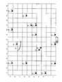
- the operational area of the AGVcan also be divided into a sectional map as shown in FIG. 2 .
- the operational areacan be divided into a plurality of sections, or cells (e.g. as in a grid or a checkerboard). These cells do not have to be squares or rectangular, and can be defined in any shape or form and by any method such as for example the Voronoi Diagram, published in “Path Planning between Two Points for a Robot Experiencing Localization Error in Known and Unknown Environments” by Howie Choset, et. al., FSR' 99 Proceedings of the International Conference on Field and Service Robotics, August, 1999, pp. 98-103 (see FIG.
- Each section of the mapcan include data correlating confidence indicators that indicates information such as the relative predicted signal quality, signal strength or error of range measurement for each beacon in the operational area, or any combination thereof. These confidence indicators can, for example, range from 0 (very poor) through 100 (very good).
- the AGVcan utilize the confidence indicators corresponding to that cell to determine which beacons to utilize.
- beacons with the highest confidence indicator valueswill be used for determining position.
- the methods and systems hereincontemplate ranking beacons according to confidence indication and then forming a subset of a plurality of beacons tat have a predetermined confidence level (e.g. forming a subset of a plurality beacons that have confidence indicators that are substantially the same as each other, are within a predetermined range of confidence indicators, or both.
- Confidence indicatorswill generally be assigned by comparing signal strength (if any), signal qualify (if any), or both against a previous signal, against a predetermined value, or both.
- systems and/or methods hereinmay include one or more data acquisition devices (e.g. which may include or be in communication with at processor) to which a radiofrequency signal is transmitted via a satellite from an AGV. Any signal recognized by the data acquisitions devices(s) may be compared with a prior signal received, with a pre-programmed signal value, or both.
- the confidence indicators for a particular cell in the sectional mapmay be updated based on signal strength, signal quality, and/or error value measured while the AGV is located in any cell.
- the error valuecan be calculated by using the Euclidean norm of the beacon position and the calculated AGV position.
- the AGVmay regularly range to one or more beacons with lower confidence levels then those used to position, only for the purpose of updating the confidence indicators.
- confidence indicatorsmay decremented in a certain amount (e.g. towards 0) when the associated error values, signal strengths, and/or signal quality exceed a predetermined threshold reflecting poor qualities/attributes (i.e. relative large error, low signal strength, poor signal quality). They may be incremented in a certain amount (e.g.
- the signal strengthis relative high, the signal quality is relatively high (when compared to other beacons). Note, it may be necessary to increase or decrease the error/signal strength/signal quality thresholds in the event that the totality of confidence indicators are 0 or 100 respectfully.
- the confidence indicators in each cellcan be based on a system of ranking based on beacon error values/signal strength/signal quality determined from AGV while ranging to the beacons while in the cell.
- the confidence indicatorscan be stored and or/transmitted to and from multiple beacons and/or multiple targets by the beacons themselves or by the AGV. It is understand that this information can be shared among several AGVs in the event more than one AGV is in use regardless where the information is stored. It is assumed that all confidence indicators are assigned a neutral value, for example, at 50, during initialization in which instance beacons are initially randomly chosen.
- an exemplary operational areain which the area has been divided into cells.
- Each cellis associated with confidence indicators. For instance when the AGV is operating in cell G 6 , it is anticipated that the confidence indicators corresponding to beacons K, E, F, H will be higher than the confidence indicators corresponding to C due to the obstacle 50 between the AGV and beacon C.
- a recurrent measurement and positioning schememay additionally or alternatively be employed such as for guiding the AGV. While the AGV is following a pathway according to a trajectory, it can continuously or intermittently predict the value and rate-of-change of this value for the reference measurement of each of the beacons. For example, in the case of range measurements, the AGV can constantly predict the range and rate-of-change of the range to each of the individual beacons.
- the AGVcan then conduct a round-robin approach to ranging to a set of beacons. Each time a new reference measurement is acquired, it can be used to update the prediction of the value of that measurement, and a new position can be calculated based on the predicted estimation of the reference measurements. Then the AGV can acquire a measurement to a next beacon and so on. If a measurement fails, the predicted value may or may not be used in the position calculation.
- Additional internal and external sensors or sensor inputse.g., velocity and acceleration inputs
- sensor inputse.g., velocity and acceleration inputs
- this conceptcan employ the operation of two separate processes inside the AGV.
- the first processcan continuously and/or intermittently update the estimated reference measurement of each of the beacons.
- a Kalman Filter or even a Double Kalman Filteras disclosed in “Fuzzy Neighborhood Filters for UWB Range Radios in Multipath Environments” by Ka C. Cheok et. al., Proc. SPIE, Vol. 6979, 69790J (2008); DOI:10.1117/12.782266 hereby incorporated by reference in its entirety for all purposes, and correct these estimates with actual measurement data.
- the second processcan, concurrently or at different times, constantly or intermittently calculate the position of the AGV using the estimated reference measurements of the beacons.
- each of the waypointscan be associated with beacons for creating a subset of beacons and then within that subset of beacons a secondary subset of beacons may be selected using confidence indicators resulting in a particularly desirable subset of beacons from the plurality of beacons.
- the updating mechanisms discussed for the present inventioncan be used for adding or subtracting beacons from the one or more subsets of beacons and such mechanisms can be employed in conjunction with or separated from the designation of particular beacons for each waypoint and/or the selection of beacons using confidence indicators.
- the AGVmay not have to calculate a selection of the beacons to be used for positioning where the beacon selection is pre-programmed. Of course, these calculations may be employed in conjunction with the techniques and methodologies of the present invention.
- the AGVcan avoid trying to take reference measurements to beacons that it can not be able to measure to, thus saving time during the path following operation. In turn, saving time for selecting the appropriate subset of beacons can allow for the AGV to increase the rate of calculating location estimates, which can improve the performance of the path following scheme.
- the AGVmay be able to anticipate the perturbation of the reference measurement to particular beacons at or adjacent the particular waypoints the next time it follows the trajectory, for improved waypoint following performance. As a result, the AGV may be able to increase the following speed, when following the trajectory, once it has driven on it before.
Landscapes
- Engineering & Computer Science (AREA)
- Physics & Mathematics (AREA)
- General Physics & Mathematics (AREA)
- Radar, Positioning & Navigation (AREA)
- Remote Sensing (AREA)
- Aviation & Aerospace Engineering (AREA)
- Automation & Control Theory (AREA)
- Probability & Statistics with Applications (AREA)
- Position Fixing By Use Of Radio Waves (AREA)
- Traffic Control Systems (AREA)
Abstract
Description
Claims (20)
Priority Applications (2)
| Application Number | Priority Date | Filing Date | Title |
|---|---|---|---|
| US12/324,310US8417444B2 (en) | 2007-11-27 | 2008-11-26 | Method and system for locating and navigating an autonomous vehicle |
| US13/798,030US8988285B2 (en) | 2007-11-27 | 2013-03-12 | Method and system for locating and navigating a target |
Applications Claiming Priority (2)
| Application Number | Priority Date | Filing Date | Title |
|---|---|---|---|
| US99041907P | 2007-11-27 | 2007-11-27 | |
| US12/324,310US8417444B2 (en) | 2007-11-27 | 2008-11-26 | Method and system for locating and navigating an autonomous vehicle |
Related Child Applications (1)
| Application Number | Title | Priority Date | Filing Date |
|---|---|---|---|
| US13/798,030ContinuationUS8988285B2 (en) | 2007-11-27 | 2013-03-12 | Method and system for locating and navigating a target |
Publications (2)
| Publication Number | Publication Date |
|---|---|
| US20090138151A1 US20090138151A1 (en) | 2009-05-28 |
| US8417444B2true US8417444B2 (en) | 2013-04-09 |
Family
ID=40670450
Family Applications (2)
| Application Number | Title | Priority Date | Filing Date |
|---|---|---|---|
| US12/324,310Expired - Fee RelatedUS8417444B2 (en) | 2007-11-27 | 2008-11-26 | Method and system for locating and navigating an autonomous vehicle |
| US13/798,030Expired - Fee RelatedUS8988285B2 (en) | 2007-11-27 | 2013-03-12 | Method and system for locating and navigating a target |
Family Applications After (1)
| Application Number | Title | Priority Date | Filing Date |
|---|---|---|---|
| US13/798,030Expired - Fee RelatedUS8988285B2 (en) | 2007-11-27 | 2013-03-12 | Method and system for locating and navigating a target |
Country Status (2)
| Country | Link |
|---|---|
| US (2) | US8417444B2 (en) |
| WO (1) | WO2009070712A2 (en) |
Cited By (32)
| Publication number | Priority date | Publication date | Assignee | Title |
|---|---|---|---|---|
| US8988285B2 (en) | 2007-11-27 | 2015-03-24 | Nav-Track, Inc. | Method and system for locating and navigating a target |
| US9374562B2 (en) | 2011-04-19 | 2016-06-21 | Ford Global Technologies, Llc | System and method for calculating a horizontal camera to target distance |
| US9399445B2 (en) | 2014-05-08 | 2016-07-26 | International Business Machines Corporation | Delegating control of a vehicle |
| US9500497B2 (en) | 2011-04-19 | 2016-11-22 | Ford Global Technologies, Llc | System and method of inputting an intended backing path |
| US9506774B2 (en) | 2011-04-19 | 2016-11-29 | Ford Global Technologies, Llc | Method of inputting a path for a vehicle and trailer |
| US9511799B2 (en) | 2013-02-04 | 2016-12-06 | Ford Global Technologies, Llc | Object avoidance for a trailer backup assist system |
| US9522677B2 (en) | 2014-12-05 | 2016-12-20 | Ford Global Technologies, Llc | Mitigation of input device failure and mode management |
| US9533683B2 (en) | 2014-12-05 | 2017-01-03 | Ford Global Technologies, Llc | Sensor failure mitigation system and mode management |
| US9555832B2 (en) | 2011-04-19 | 2017-01-31 | Ford Global Technologies, Llc | Display system utilizing vehicle and trailer dynamics |
| US9566911B2 (en) | 2007-03-21 | 2017-02-14 | Ford Global Technologies, Llc | Vehicle trailer angle detection system and method |
| US9592851B2 (en) | 2013-02-04 | 2017-03-14 | Ford Global Technologies, Llc | Control modes for a trailer backup assist system |
| US9854209B2 (en) | 2011-04-19 | 2017-12-26 | Ford Global Technologies, Llc | Display system utilizing vehicle and trailer dynamics |
| US9896130B2 (en) | 2015-09-11 | 2018-02-20 | Ford Global Technologies, Llc | Guidance system for a vehicle reversing a trailer along an intended backing path |
| US9926008B2 (en) | 2011-04-19 | 2018-03-27 | Ford Global Technologies, Llc | Trailer backup assist system with waypoint selection |
| US9969428B2 (en) | 2011-04-19 | 2018-05-15 | Ford Global Technologies, Llc | Trailer backup assist system with waypoint selection |
| WO2018097836A1 (en)* | 2016-11-28 | 2018-05-31 | Empire Technology Development Llc | Surveillance route management for a device |
| US10090909B2 (en) | 2017-02-24 | 2018-10-02 | At&T Mobility Ii Llc | Maintaining antenna connectivity based on communicated geographic information |
| US10112646B2 (en) | 2016-05-05 | 2018-10-30 | Ford Global Technologies, Llc | Turn recovery human machine interface for trailer backup assist |
| WO2019037939A1 (en)* | 2017-08-23 | 2019-02-28 | Innovative Dragon Ltd. | NAVIGATION PROCESS AND NAVIGATION DEVICE |
| US10304343B2 (en) | 2017-02-24 | 2019-05-28 | At&T Mobility Ii Llc | Flight plan implementation, generation, and management for aerial devices |
| US10393852B2 (en) | 2015-09-16 | 2019-08-27 | Here Global B.V. | Method and system of location estimation and navigation of autonomous vehicles |
| US10589931B2 (en) | 2016-09-30 | 2020-03-17 | Staples, Inc. | Hybrid modular storage fetching system |
| US10683171B2 (en) | 2016-09-30 | 2020-06-16 | Staples, Inc. | Hybrid modular storage fetching system |
| US10803420B2 (en) | 2016-09-30 | 2020-10-13 | Staples, Inc. | Hybrid modular storage fetching system |
| US11084410B1 (en) | 2018-08-07 | 2021-08-10 | Staples, Inc. | Automated guided vehicle for transporting shelving units |
| US11119487B2 (en) | 2018-12-31 | 2021-09-14 | Staples, Inc. | Automated preparation of deliveries in delivery vehicles using automated guided vehicles |
| US11124401B1 (en) | 2019-03-31 | 2021-09-21 | Staples, Inc. | Automated loading of delivery vehicles |
| US11125575B2 (en) | 2019-11-20 | 2021-09-21 | Here Global B.V. | Method and apparatus for estimating a location of a vehicle |
| US11180069B2 (en) | 2018-12-31 | 2021-11-23 | Staples, Inc. | Automated loading of delivery vehicles using automated guided vehicles |
| US11590997B1 (en) | 2018-08-07 | 2023-02-28 | Staples, Inc. | Autonomous shopping cart |
| US11630447B1 (en) | 2018-08-10 | 2023-04-18 | Staples, Inc. | Automated guided vehicle for transporting objects |
| US20230204706A1 (en)* | 2020-11-30 | 2023-06-29 | Motional Ad Llc | Localization of vehicles using beacons |
Families Citing this family (26)
| Publication number | Priority date | Publication date | Assignee | Title |
|---|---|---|---|---|
| US7991521B2 (en)* | 2006-02-01 | 2011-08-02 | Jervis B. Webb Company | Variable path automated guided vehicle |
| JP5503419B2 (en)* | 2010-06-03 | 2014-05-28 | 株式会社日立製作所 | Automated guided vehicle and travel control method |
| JP5786941B2 (en)* | 2011-08-25 | 2015-09-30 | 日産自動車株式会社 | Autonomous driving control system for vehicles |
| US20130155102A1 (en)* | 2011-12-20 | 2013-06-20 | Honeywell International Inc. | Systems and methods of accuracy mapping in a location tracking system |
| US8788121B2 (en) | 2012-03-09 | 2014-07-22 | Proxy Technologies, Inc. | Autonomous vehicle and method for coordinating the paths of multiple autonomous vehicles |
| US8874360B2 (en) | 2012-03-09 | 2014-10-28 | Proxy Technologies Inc. | Autonomous vehicle and method for coordinating the paths of multiple autonomous vehicles |
| EP2875471B1 (en)* | 2012-07-23 | 2021-10-27 | Apple Inc. | Method of providing image feature descriptors |
| US8825373B1 (en)* | 2012-12-05 | 2014-09-02 | Google Inc. | Correcting path errors for vehicle navigation |
| JP6111179B2 (en)* | 2013-10-22 | 2017-04-05 | 日立建機株式会社 | Autonomous traveling system for dump truck |
| DE102014205170A1 (en)* | 2014-03-20 | 2015-11-26 | Bayerische Motoren Werke Aktiengesellschaft | Method and device for determining a trajectory for a vehicle |
| WO2015192902A1 (en)* | 2014-06-19 | 2015-12-23 | Husqvarna Ab | Automatic beacon position determination |
| US10301018B2 (en) | 2014-10-17 | 2019-05-28 | Tyco Fire & Security Gmbh | Fixed drone visualization in security systems |
| US9612722B2 (en) | 2014-10-31 | 2017-04-04 | Microsoft Technology Licensing, Llc | Facilitating interaction between users and their environments using sounds |
| WO2017083424A1 (en)* | 2015-11-09 | 2017-05-18 | Simbe Robotics, Inc. | Method for tracking stock level within a store |
| US10935626B2 (en)* | 2015-12-02 | 2021-03-02 | Koninklijke Philips N.V. | System, control device and method for position detection |
| JP6728404B2 (en) | 2016-05-19 | 2020-07-22 | シムビ ロボティクス, インコーポレイテッドSimbe Robotics, Inc. | How to track product placement on store shelves |
| US11941579B2 (en) | 2016-09-20 | 2024-03-26 | Aislan Gomide Foina | Autonomous vehicles performing inventory management |
| DE102016221106B4 (en) | 2016-10-26 | 2024-05-16 | Volkswagen Aktiengesellschaft | Method and system for external control of an autonomous vehicle |
| CN107133555B (en)* | 2017-01-20 | 2020-10-23 | 西南电子技术研究所(中国电子科技集团公司第十研究所) | Method for identifying 8-character motion track target |
| EP3396417A1 (en) | 2017-04-25 | 2018-10-31 | Vineyard Cloud GmbH | Positioning system for positioning moving objects in land parcels of specialised crop areas |
| US11112796B2 (en)* | 2017-08-08 | 2021-09-07 | Uatc, Llc | Object motion prediction and autonomous vehicle control |
| CA3104284A1 (en) | 2018-06-20 | 2019-12-26 | Simbe Robotics, Inc | Method for managing click and delivery shopping events |
| US11086332B2 (en)* | 2019-07-16 | 2021-08-10 | Passion Mobility Ltd. | Navigation method and system |
| CA3162894A1 (en) | 2019-11-25 | 2021-06-03 | Simbe Robotics, Inc | Method for tracking and maintaining inventory in a store |
| CN115092184B (en) | 2022-07-20 | 2025-03-07 | 江苏徐工工程机械研究院有限公司 | Vehicle control method, device and vehicle |
| US20250162581A1 (en) | 2023-11-20 | 2025-05-22 | GM Global Technology Operations LLC | Dynamic and adaptive agv speed and distance |
Citations (16)
| Publication number | Priority date | Publication date | Assignee | Title |
|---|---|---|---|---|
| WO2000038460A1 (en) | 1998-12-19 | 2000-06-29 | Koninklijke Philips Electronics N.V. | Location beacon system |
| US6298306B1 (en) | 1999-07-28 | 2001-10-02 | Motorola, Inc. | Vehicle locating system utilizing global positioning |
| US6300905B1 (en) | 1999-10-05 | 2001-10-09 | Lucent Technologies Inc. | Location finding using a single base station in CDMA/TDMA systems |
| WO2005011153A1 (en) | 2003-07-24 | 2005-02-03 | Utstarcom Korea Limited | System and method for tracking position of a mobile unit using beacons in a mobile communication system |
| US20050136845A1 (en)* | 2003-09-22 | 2005-06-23 | Fujitsu Limited | Method and apparatus for location determination using mini-beacons |
| US20050171684A1 (en) | 2001-08-29 | 2005-08-04 | Paul Turner | Vehicle guidance software, method and system |
| US20050270234A1 (en)* | 2003-06-09 | 2005-12-08 | Wolf Edward A | Direction and distance finder for locating distress signals |
| US20060147088A1 (en)* | 2005-01-04 | 2006-07-06 | Deere & Company, A Delaware Corporation | Method and system for guiding a vehicle with vision enhancement |
| US7110881B2 (en) | 2003-10-07 | 2006-09-19 | Deere & Company | Modular path planner |
| US7132982B2 (en) | 1999-03-05 | 2006-11-07 | Rannock Corporation | Method and apparatus for accurate aircraft and vehicle tracking |
| US7286624B2 (en) | 2003-07-03 | 2007-10-23 | Navcom Technology Inc. | Two-way RF ranging system and method for local positioning |
| US20070247366A1 (en)* | 2003-10-22 | 2007-10-25 | Smith Derek M | Wireless postion location and tracking system |
| US7403783B2 (en) | 2004-02-17 | 2008-07-22 | Jadi, Inc. | Navigation system |
| US20080234930A1 (en) | 2007-03-21 | 2008-09-25 | Jadi Inc. | Navigation unit and base station |
| US20080262669A1 (en) | 2006-09-22 | 2008-10-23 | Jadi, Inc. | Autonomous vehicle controller |
| US7880608B2 (en) | 1998-03-23 | 2011-02-01 | Time Domain Corporation | System and method for person or object position location utilizing impulse radio |
Family Cites Families (1)
| Publication number | Priority date | Publication date | Assignee | Title |
|---|---|---|---|---|
| WO2009070712A2 (en) | 2007-11-27 | 2009-06-04 | Jadi, Inc. | Method and system for locating and navigating a target |
- 2008
- 2008-11-26WOPCT/US2008/084936patent/WO2009070712A2/enactiveApplication Filing
- 2008-11-26USUS12/324,310patent/US8417444B2/ennot_activeExpired - Fee Related
- 2013
- 2013-03-12USUS13/798,030patent/US8988285B2/ennot_activeExpired - Fee Related
Patent Citations (16)
| Publication number | Priority date | Publication date | Assignee | Title |
|---|---|---|---|---|
| US7880608B2 (en) | 1998-03-23 | 2011-02-01 | Time Domain Corporation | System and method for person or object position location utilizing impulse radio |
| WO2000038460A1 (en) | 1998-12-19 | 2000-06-29 | Koninklijke Philips Electronics N.V. | Location beacon system |
| US7132982B2 (en) | 1999-03-05 | 2006-11-07 | Rannock Corporation | Method and apparatus for accurate aircraft and vehicle tracking |
| US6298306B1 (en) | 1999-07-28 | 2001-10-02 | Motorola, Inc. | Vehicle locating system utilizing global positioning |
| US6300905B1 (en) | 1999-10-05 | 2001-10-09 | Lucent Technologies Inc. | Location finding using a single base station in CDMA/TDMA systems |
| US20050171684A1 (en) | 2001-08-29 | 2005-08-04 | Paul Turner | Vehicle guidance software, method and system |
| US20050270234A1 (en)* | 2003-06-09 | 2005-12-08 | Wolf Edward A | Direction and distance finder for locating distress signals |
| US7286624B2 (en) | 2003-07-03 | 2007-10-23 | Navcom Technology Inc. | Two-way RF ranging system and method for local positioning |
| WO2005011153A1 (en) | 2003-07-24 | 2005-02-03 | Utstarcom Korea Limited | System and method for tracking position of a mobile unit using beacons in a mobile communication system |
| US20050136845A1 (en)* | 2003-09-22 | 2005-06-23 | Fujitsu Limited | Method and apparatus for location determination using mini-beacons |
| US7110881B2 (en) | 2003-10-07 | 2006-09-19 | Deere & Company | Modular path planner |
| US20070247366A1 (en)* | 2003-10-22 | 2007-10-25 | Smith Derek M | Wireless postion location and tracking system |
| US7403783B2 (en) | 2004-02-17 | 2008-07-22 | Jadi, Inc. | Navigation system |
| US20060147088A1 (en)* | 2005-01-04 | 2006-07-06 | Deere & Company, A Delaware Corporation | Method and system for guiding a vehicle with vision enhancement |
| US20080262669A1 (en) | 2006-09-22 | 2008-10-23 | Jadi, Inc. | Autonomous vehicle controller |
| US20080234930A1 (en) | 2007-03-21 | 2008-09-25 | Jadi Inc. | Navigation unit and base station |
Non-Patent Citations (11)
| Title |
|---|
| "Path Planning between Two Points for a Robot Experiencing Localization Error in Known and Unknown Environments", Howie Choset, Marco La Civita, and Jong Chul Park, 1999. |
| "Sensor Based Motion Planning: The Hierarchical Generalized Voronoi Graph", Howie Choset, and Joel Burdick, Carnegie Mellon University, Pittsburgh, PA, USA, 1996. |
| Canadian Intellectual Property Office action in Application No. 2554417 dated Jan. 29, 2010. |
| International Search Report and Written Opinion of the International Searching Authority dated Jun. 29, 2009 for Serial No. PCT/US2008/084936. |
| US Office Action in U.S. Appl. No. 11/857,700 dated Aug. 3, 2010. |
| US Office Action in U.S. Appl. No. 11/857,700 dated Mar. 24, 2010. |
| US Office Action in U.S. Appl. No. 11/968,884 dated Aug. 24, 2010. |
| US Office Action in U.S. Appl. No. 11/968,884 dated Jan. 14, 2011. |
| US Office Action in U.S. Appl. No. 12/053,208 dated Jun. 30, 2011. |
| US Office Action in U.S. Appl. No. 12/053,221 dated Aug. 31, 2010. |
| US Office Action in U.S. Appl. No. 12/053,221 dated Feb. 7, 2011. |
Cited By (47)
| Publication number | Priority date | Publication date | Assignee | Title |
|---|---|---|---|---|
| US9971943B2 (en) | 2007-03-21 | 2018-05-15 | Ford Global Technologies, Llc | Vehicle trailer angle detection system and method |
| US9566911B2 (en) | 2007-03-21 | 2017-02-14 | Ford Global Technologies, Llc | Vehicle trailer angle detection system and method |
| US8988285B2 (en) | 2007-11-27 | 2015-03-24 | Nav-Track, Inc. | Method and system for locating and navigating a target |
| US9555832B2 (en) | 2011-04-19 | 2017-01-31 | Ford Global Technologies, Llc | Display system utilizing vehicle and trailer dynamics |
| US9374562B2 (en) | 2011-04-19 | 2016-06-21 | Ford Global Technologies, Llc | System and method for calculating a horizontal camera to target distance |
| US9506774B2 (en) | 2011-04-19 | 2016-11-29 | Ford Global Technologies, Llc | Method of inputting a path for a vehicle and trailer |
| US9500497B2 (en) | 2011-04-19 | 2016-11-22 | Ford Global Technologies, Llc | System and method of inputting an intended backing path |
| US9854209B2 (en) | 2011-04-19 | 2017-12-26 | Ford Global Technologies, Llc | Display system utilizing vehicle and trailer dynamics |
| US10609340B2 (en) | 2011-04-19 | 2020-03-31 | Ford Global Technologies, Llc | Display system utilizing vehicle and trailer dynamics |
| US9926008B2 (en) | 2011-04-19 | 2018-03-27 | Ford Global Technologies, Llc | Trailer backup assist system with waypoint selection |
| US9969428B2 (en) | 2011-04-19 | 2018-05-15 | Ford Global Technologies, Llc | Trailer backup assist system with waypoint selection |
| US9511799B2 (en) | 2013-02-04 | 2016-12-06 | Ford Global Technologies, Llc | Object avoidance for a trailer backup assist system |
| US9592851B2 (en) | 2013-02-04 | 2017-03-14 | Ford Global Technologies, Llc | Control modes for a trailer backup assist system |
| US10421434B2 (en) | 2014-05-08 | 2019-09-24 | International Business Machines Corporation | Delegating control of a vehicle |
| US9399445B2 (en) | 2014-05-08 | 2016-07-26 | International Business Machines Corporation | Delegating control of a vehicle |
| US9884611B2 (en) | 2014-05-08 | 2018-02-06 | International Business Machines Corporation | Delegating control of a vehicle |
| US9533683B2 (en) | 2014-12-05 | 2017-01-03 | Ford Global Technologies, Llc | Sensor failure mitigation system and mode management |
| US9522677B2 (en) | 2014-12-05 | 2016-12-20 | Ford Global Technologies, Llc | Mitigation of input device failure and mode management |
| US9896130B2 (en) | 2015-09-11 | 2018-02-20 | Ford Global Technologies, Llc | Guidance system for a vehicle reversing a trailer along an intended backing path |
| US10393852B2 (en) | 2015-09-16 | 2019-08-27 | Here Global B.V. | Method and system of location estimation and navigation of autonomous vehicles |
| US10112646B2 (en) | 2016-05-05 | 2018-10-30 | Ford Global Technologies, Llc | Turn recovery human machine interface for trailer backup assist |
| US10683171B2 (en) | 2016-09-30 | 2020-06-16 | Staples, Inc. | Hybrid modular storage fetching system |
| US11893535B2 (en) | 2016-09-30 | 2024-02-06 | Staples, Inc. | Hybrid modular storage fetching system |
| US12037195B2 (en) | 2016-09-30 | 2024-07-16 | Staples, Inc. | Hybrid modular storage fetching system |
| US11697554B2 (en) | 2016-09-30 | 2023-07-11 | Staples, Inc. | Hybrid modular storage fetching system |
| US10589931B2 (en) | 2016-09-30 | 2020-03-17 | Staples, Inc. | Hybrid modular storage fetching system |
| US11702287B2 (en) | 2016-09-30 | 2023-07-18 | Staples, Inc. | Hybrid modular storage fetching system |
| US10803420B2 (en) | 2016-09-30 | 2020-10-13 | Staples, Inc. | Hybrid modular storage fetching system |
| WO2018097836A1 (en)* | 2016-11-28 | 2018-05-31 | Empire Technology Development Llc | Surveillance route management for a device |
| US10637559B2 (en) | 2017-02-24 | 2020-04-28 | At&T Mobility Ii Llc | Maintaining antenna connectivity based on communicated geographic information |
| US10991257B2 (en) | 2017-02-24 | 2021-04-27 | At&T Mobility Ii Llc | Navigation systems and methods for drones |
| US20210241632A1 (en)* | 2017-02-24 | 2021-08-05 | At&T Mobility Ii Llc | Navigation systems and methods for drones |
| US11721221B2 (en)* | 2017-02-24 | 2023-08-08 | Hyundai Motor Company | Navigation systems and methods for drones |
| US10090909B2 (en) | 2017-02-24 | 2018-10-02 | At&T Mobility Ii Llc | Maintaining antenna connectivity based on communicated geographic information |
| US10304343B2 (en) | 2017-02-24 | 2019-05-28 | At&T Mobility Ii Llc | Flight plan implementation, generation, and management for aerial devices |
| CN110869703A (en)* | 2017-08-23 | 2020-03-06 | 创新龙有限公司 | Navigation method and navigation equipment |
| WO2019037939A1 (en)* | 2017-08-23 | 2019-02-28 | Innovative Dragon Ltd. | NAVIGATION PROCESS AND NAVIGATION DEVICE |
| US11084410B1 (en) | 2018-08-07 | 2021-08-10 | Staples, Inc. | Automated guided vehicle for transporting shelving units |
| US11590997B1 (en) | 2018-08-07 | 2023-02-28 | Staples, Inc. | Autonomous shopping cart |
| US11630447B1 (en) | 2018-08-10 | 2023-04-18 | Staples, Inc. | Automated guided vehicle for transporting objects |
| US11180069B2 (en) | 2018-12-31 | 2021-11-23 | Staples, Inc. | Automated loading of delivery vehicles using automated guided vehicles |
| US11119487B2 (en) | 2018-12-31 | 2021-09-14 | Staples, Inc. | Automated preparation of deliveries in delivery vehicles using automated guided vehicles |
| US11124401B1 (en) | 2019-03-31 | 2021-09-21 | Staples, Inc. | Automated loading of delivery vehicles |
| US11656088B2 (en) | 2019-11-20 | 2023-05-23 | Here Global B.V. | Method and apparatus for estimating a location of a vehicle |
| US11125575B2 (en) | 2019-11-20 | 2021-09-21 | Here Global B.V. | Method and apparatus for estimating a location of a vehicle |
| US20230204706A1 (en)* | 2020-11-30 | 2023-06-29 | Motional Ad Llc | Localization of vehicles using beacons |
| US12038521B2 (en)* | 2020-11-30 | 2024-07-16 | Motional Ad Llc | Localization of vehicles using beacons |
Also Published As
| Publication number | Publication date |
|---|---|
| WO2009070712A2 (en) | 2009-06-04 |
| US20150022400A1 (en) | 2015-01-22 |
| WO2009070712A3 (en) | 2009-08-27 |
| US8988285B2 (en) | 2015-03-24 |
| US20090138151A1 (en) | 2009-05-28 |
Similar Documents
| Publication | Publication Date | Title |
|---|---|---|
| US8417444B2 (en) | Method and system for locating and navigating an autonomous vehicle | |
| EP3884353B1 (en) | Detecting a location of an autonomous device | |
| CN101793528B (en) | System and method of lane path estimation using sensor fusion | |
| US7970491B2 (en) | Robot localization system | |
| KR101796322B1 (en) | Apparatus and method for detecting location information using navigation algorithm | |
| EP3696576B1 (en) | Robotic vehicle for soil cultivation | |
| US11005310B2 (en) | Method for determining the position of a charging station for the wireless transfer of electric power to a vehicle | |
| US20170248426A1 (en) | Calibration Methods and Systems for an Autonomous Navigation Vehicle | |
| US6545638B2 (en) | Correcting a prior dead reckoning determined position measurement using GPS when GPS is later acquired | |
| US20160261989A1 (en) | Predictive directional antenna targeting | |
| US20170229023A1 (en) | Communication link accessibility aware navigation | |
| KR20170088228A (en) | Map building system and its method based on multi-robot localization | |
| US20200034646A1 (en) | Unmanned Aerial Localization and Orientation | |
| KR20150051747A (en) | Method for determining location of vehicle | |
| KR101704634B1 (en) | Apparatus and method for generating driving route of autonomous vehicle and method for controlling driving of autonomous vehicle | |
| EP3997485B1 (en) | Enhancing sensitivity to reflected gnss signals | |
| US7489255B2 (en) | Self-position identification apparatus and self-position identification method | |
| KR20230082885A (en) | Performance evaluation methods and perfromace evaluation system for autonomous driving robot | |
| KR101673749B1 (en) | Positioning system using directive communication and method thereof | |
| Dehghan et al. | Path planning for localization of an RF source by multiple UAVs on the Crammer-Rao Lower Bound | |
| EP3696575B1 (en) | Robotic vehicle for soil cultivation | |
| JP6755417B1 (en) | Relative position determination device, relative position determination method, and relative position determination program | |
| US12436250B2 (en) | Navigation systems and methods for an autonomous device | |
| US12025458B2 (en) | Method and system for positioning a vehicle using an image-capturing device | |
| KR20170142335A (en) | Navigation and control method thereof |
Legal Events
| Date | Code | Title | Description |
|---|---|---|---|
| AS | Assignment | Owner name:JADI INC., MICHIGAN Free format text:ASSIGNMENT OF ASSIGNORS INTEREST;ASSIGNORS:SMID, EDZKO;STIGLICH, TOM;REEL/FRAME:022476/0371 Effective date:20090331 | |
| AS | Assignment | Owner name:NAV-TRACK, INC., MICHIGAN Free format text:CHANGE OF NAME;ASSIGNOR:JADI, INC.;REEL/FRAME:023854/0518 Effective date:20091130 | |
| STCF | Information on status: patent grant | Free format text:PATENTED CASE | |
| FPAY | Fee payment | Year of fee payment:4 | |
| FEPP | Fee payment procedure | Free format text:MAINTENANCE FEE REMINDER MAILED (ORIGINAL EVENT CODE: REM.); ENTITY STATUS OF PATENT OWNER: SMALL ENTITY | |
| AS | Assignment | Owner name:HAILO TECHNOLOGIES, LLC, CALIFORNIA Free format text:ASSIGNMENT OF ASSIGNORS INTEREST;ASSIGNOR:NAV-TRACK, INC.;REEL/FRAME:055706/0867 Effective date:20200224 | |
| FEPP | Fee payment procedure | Free format text:7.5 YR SURCHARGE - LATE PMT W/IN 6 MO, SMALL ENTITY (ORIGINAL EVENT CODE: M2555); ENTITY STATUS OF PATENT OWNER: SMALL ENTITY | |
| MAFP | Maintenance fee payment | Free format text:PAYMENT OF MAINTENANCE FEE, 8TH YR, SMALL ENTITY (ORIGINAL EVENT CODE: M2552); ENTITY STATUS OF PATENT OWNER: SMALL ENTITY Year of fee payment:8 | |
| FEPP | Fee payment procedure | Free format text:MAINTENANCE FEE REMINDER MAILED (ORIGINAL EVENT CODE: REM.); ENTITY STATUS OF PATENT OWNER: SMALL ENTITY | |
| LAPS | Lapse for failure to pay maintenance fees | Free format text:PATENT EXPIRED FOR FAILURE TO PAY MAINTENANCE FEES (ORIGINAL EVENT CODE: EXP.); ENTITY STATUS OF PATENT OWNER: SMALL ENTITY | |
| STCH | Information on status: patent discontinuation | Free format text:PATENT EXPIRED DUE TO NONPAYMENT OF MAINTENANCE FEES UNDER 37 CFR 1.362 | |
| FP | Lapsed due to failure to pay maintenance fee | Effective date:20250409 |