US8416959B2 - Hearing enhancement system and components thereof - Google Patents
Hearing enhancement system and components thereofDownload PDFInfo
- Publication number
- US8416959B2 US8416959B2US12/551,805US55180509AUS8416959B2US 8416959 B2US8416959 B2US 8416959B2US 55180509 AUS55180509 AUS 55180509AUS 8416959 B2US8416959 B2US 8416959B2
- Authority
- US
- United States
- Prior art keywords
- audio signal
- hearing
- operably coupled
- signal
- anr
- Prior art date
- Legal status (The legal status is an assumption and is not a legal conclusion. Google has not performed a legal analysis and makes no representation as to the accuracy of the status listed.)
- Expired - Fee Related, expires
Links
Images


Classifications
- H—ELECTRICITY
- H04—ELECTRIC COMMUNICATION TECHNIQUE
- H04R—LOUDSPEAKERS, MICROPHONES, GRAMOPHONE PICK-UPS OR LIKE ACOUSTIC ELECTROMECHANICAL TRANSDUCERS; DEAF-AID SETS; PUBLIC ADDRESS SYSTEMS
- H04R5/00—Stereophonic arrangements
- H04R5/033—Headphones for stereophonic communication
Definitions
- This inventionrelates generally to mixed signal processing and more particularly to audio signal processing.
- Headphonesare known to provide an improved listening experience for listening to a variety of audio sources.
- headphonesmay be used in commercial settings (e.g., recording studio, audio laboratories, etc.) to listen to audio content (e.g., music, audio signals, voice signals, etc.) with little to no interference from external sources (e.g., background noise).
- headphonesmay be used in recreational settings (e.g., at home, at the office, etc.) to listen to audio output by a digital audio player (e.g., MP3), an AM/FM radio, a television, a CD player, a DVD player, etc. with reduced interference from external sources and/or for private listening.
- a digital audio playere.g., MP3
- AM/FM radioAM/FM radio
- a headphoneincludes one or more speakers (typically two) that can be held closely to the user's ears and circuitry for connecting to an audio source.
- ear-bud headphonesare held close to the user's ears by a pressure fit and include a male audio jack for connecting to a source.
- the headphonemay have an ear-cup or on-ear design that fit over the ears; may have a circumaural or full size design that completely surround the ears; or may have a supra-aural design that are light-weight and sits on the ears.
- Headsetsare known to provide “hands-free” operation of a communication device (e.g., landline telephone, cellular telephone, voice over IP telephone, two-way radio, etc.).
- a headsetis essentially a headphone with one or more microphones.
- a headsetprovides the listening features of a headset with the added ability to transmit voice and/or other audio signals.
- some headphones and/or headsetsinclude noise cancelling circuitry.
- the noise cancelling circuitryincludes one or more omni-directional microphones to receive noise that is proximal to user but does not receive noise that is further away.
- the noise received by the microphonemay be filtered, amplified, and phase inverted to cause a reduction in proximal noise to the user.
- An audio signalmay also be combined with the noise cancelling circuitry in a manner that allows the system to reproduce the audio signal. In this manner, the audio signal provided to the speaker(s) of the headset or headphone includes the desired audio signal and an inverted version of the noise to be suppressed.
- noise cancelling headsets and/or headphoneswork well in many situations where the noise level is modest (e.g., on an airplane, in a building, etc.), as the noise level increases, the noise cancelling circuitry becomes unstable and may increase the noise level. For instance, when headsets and/or headphones are used in extremely loud environments (e.g., helicopters, jets, blasting sites (e.g., demolition, military battles, etc.), at a race track, etc.) conventional noise cancelling circuitry is inadequate and a more robust noise cancellation technique is needed. Even with the more robust noise cancellation circuitry, many persons who are regularly exposed to extremely loud environments experience noise-induced hearing loss.
- extremely loud environmentse.g., helicopters, jets, blasting sites (e.g., demolition, military battles, etc.), at a race track, etc.
- conventional noise cancelling circuitryis inadequate and a more robust noise cancellation technique is needed.
- Even with the more robust noise cancellation circuitrymany persons who are regularly exposed to extremely loud environments experience noise-induced hearing loss.
- headsets/headphonesin loud environments is to allow desired surrounding environmental audio signals to be heard while suppressing the undesired noise.
- This issuemay be referred to as localization.
- a usermay be involved in a communication, thus the incoming voice signals are desired and the background noise (e.g., wind, engine noise, etc.) and loud transient noise (e.g., a gun shot, a engine back-firing, etc.) are undesired.
- the desired audio signalsshould pass through to the speakers (i.e., hear-through) while the background noise and transient noise should be suppressed.
- headsets/headphones designed for extremely loud environmentsaddress one or more of the above issues, they do not address some of the other issues.
- a headset/headphonemay address the loud background noises but does not handle the loud transient noises well or does not provide an adequate level of hear-through considering the hearing profile of the listener.
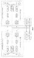
- FIG. 1is a schematic block diagram of an embodiment of a hearing enhancement system in accordance with the present invention
- FIG. 2is a schematic block diagram of an embodiment of an active noise reduction circuit in accordance with the present invention.
- FIG. 3is a schematic block diagram of another embodiment of an active noise reduction circuit in accordance with the present invention.
- FIG. 4is a schematic block diagram of an embodiment of a microphone circuit and an audio processing module in accordance with the present invention.
- FIG. 5is a schematic block diagram of an embodiment of an audio processing module and/or a digital audio processing module in accordance with the present invention
- FIG. 6is a schematic block diagram of an embodiment of a microphone circuit in accordance with the present invention.
- FIG. 7is a schematic block diagram of an embodiment of a microphone circuit in accordance with the present invention.
- FIG. 8is a schematic block diagram of another embodiment of a hearing enhancement system in accordance with the present invention.
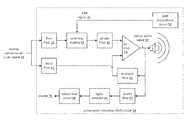
- FIG. 1is a schematic block diagram of an embodiment of a hearing enhancement system 10 that includes a left ear unit 12 , a right ear unit 14 , and a control module 16 .
- Each of the left and right ear units 12 and 14includes a cup housing 42 , a circuit 15 , and may further include a seal 40 .
- the circuit 15includes a microphone circuit 18 , an audio processing module 20 , a digital audio processing module 22 , and an active noise reduction (ANR) circuit 24 .
- ANRactive noise reduction
- the hearing enhancement system 10provides hear-through with reduced localization issues, provides hearing compensation (e.g., hearing aid), and provides active noise reduction for suppressing loud background noises and loud transient noises. As such, the hearing enhancement system 10 is well suited for use in extremely noisy environments.
- the audio processing module 20 , and the digital audio processing module 22may be separate processing modules or may be a shared processing module.
- the control module 16is a separate processing module.
- Such a processing modulemay be a single processing device or a plurality of processing devices.
- the processing devicemay be a microprocessor, micro-controller, digital signal processor, microcomputer, central processing unit, field programmable gate array, programmable logic device, state machine, logic circuitry, analog circuitry, digital circuitry, and/or any device that manipulates signals (analog and/or digital) based on hard coding of the circuitry, inherent functionality of the circuitry (e.g., an operational amplifier amplifies a signal), and/or operational instructions.
- the processing modulemay have an associated memory and/or memory element, which may be a single memory device, a plurality of memory devices, and/or embedded circuitry of the processing module.
- a memory devicemay be a read-only memory, random access memory, volatile memory, non-volatile memory, static memory, dynamic memory, flash memory, cache memory, and/or any device that stores digital information.
- the processing moduleincludes more than one processing device, the processing devices may be centrally located (e.g., directly coupled together via a wired and/or wireless bus structure) or may be distributedly located (e.g., cloud computing via indirect coupling via a local area network and/or a wide area network).
- the processing moduleimplements one or more of its functions via a state machine, analog circuitry, digital circuitry, and/or logic circuitry
- the memory and/or memory element storing the corresponding operational instructionsmay be embedded within, or external to, the circuitry comprising the state machine, analog circuitry, digital circuitry, and/or logic circuitry.
- the memory elementstores, and the processing module executes, hard coded and/or operational instructions corresponding to at least some of the steps and/or functions illustrated in FIGS. 1-8 .
- the left cup-shaped housing 42houses the circuit 15 and is mechanically coupled to a left seal 40 .
- the right cup-shaped housing 42houses the right circuit 15 and is mechanically coupled to the right seal 40 .
- the seals 40may compromise a torus (e.g., doughnut) shaped structure where an outside pliable material (e.g., plastic, cloth, leather) is filled with a material (e.g., foam, gas, gel, liquid) that compresses as the cup housing 42 is pressed against the user's head around the user's ear.
- the seals 40may provide acoustic isolation of the inside of the cup housing 42 from the outside of the cup housing 42 while providing the user greater comfort.
- a bladdermay be utilized between the cup housing 42 and a helmet worn by the user where the helmet substantially fits on the outside of both of the cup housings 42 .
- the bladdermay expand between the helmet and cup housing 42 so as to force the cup housing 42 and the seal 40 against the head to maximize a consistent contact all the way around the seal 40 and the head producing an improved level of acoustic isolation.
- the bladderis inflatable with air, gas, or a liquid, to provide an adjustable fit to the user's head and ears to improve the consistency of the effectiveness of the seal 40 .
- the control module 16activates the hearing enhanced system 10 in one of a plurality of modes (e.g., which functions are activated and how they will operate). For instance, the control module 16 may activate the hear-through function only, the active noise reduction (ANR) function only, or both the hear-through function and the ANR function. In another instance, the control module 16 may activate the digital audio processing module 22 to operate in an auto-adaptive mode to self-vary operational parameters as a function of the environmental noise, which may include starting point operational parameters (e.g., parameters for an expected noise environment). In addition, the control module 16 may deactivate the hearing enhanced system 10 .
- modese.g., which functions are activated and how they will operate. For instance, the control module 16 may activate the hear-through function only, the active noise reduction (ANR) function only, or both the hear-through function and the ANR function. In another instance, the control module 16 may activate the digital audio processing module 22 to operate in an auto-adaptive mode to self-vary operational parameters as a function of the
- the control module 16may also include a reset function that resets the hearing enhancement system 10 to default settings (e.g., volume level, equalization, compression, etc.) and/or default modes of operation (e.g., both hear-through and ANR active).
- the control module 16may also specify operational parameters for activated functions including parameters or auto-adaptive parameter ranges for multi-band equalization, noise reduction, and multi-hearing modes for producing the hearing compensated audio signal based on the hearing compensation data.
- the microphone circuits 18 of the left and/or right ear unit 12 and 14receive acoustic vibrations 26 in a proximal environment.
- the acoustic vibrations 26may correspond to speech, noise, and/or any other sound (e.g., music, foot-steps, wind, etc.).
- the microphone circuits 18(embodiments of which will be described in greater detail with reference to FIGS. 4 , 6 , and 7 ) generate an audio signal 28 based on the acoustic vibration 26 .
- the audio signal 28may be an analog signal is amplified, filtered, level shifted, etc., by the microphone circuit 18 .
- the audio processing module 20is enabled to generate a representation 30 of the left audio signal 28 .
- the audio processing module 20performs the hear-through function when it is enabled.
- the audio processing module 20receives the audio signal 28 in the analog domain.
- the audio signal 28includes a desired signal component (e.g., voice signals and/or any other sounds of interest (e.g., distant gun fire, verbal signals, sounds associated with movement, etc.)) and undesired signal component (e.g., background noise, wind, loud transients, etc.).
- the audio processing module 20may include an analog to digital converter that converts the audio signal 28 into a digital signal. In the digital domain, the audio processing module 20 separates the desired signal component from the undesired signal component. It then attenuates the undesired signal component and passes the desired signal component substantially unattenuated. This may be done in a variety of ways. For example, the audio processing module 20 may analyze the digital signal to detect the undesired signal component (e.g., noise, transients, etc.) using one or more matched filters, audio correlation, audio codebook look ups, etc. Having isolated the undesired signal component, the audio processing module 20 filters it to produce the representation 30 of the audio signal 28 .
- the undesired signal componente.g., noise, transients, etc.
- the audio processing module 20may be enabled to convert the audio signal 28 into a digital signal and pass the digital signal onto the digital audio processing module 22 as the representation 30 of the audio signal 28 . In this mode, whatever digital audio processing that is enabled is performed by the digital audio processing module 22 .
- the digital audio processing module 22When the digital audio processing module 22 is enabled, it compensates the representation 30 of the left audio signal 28 based on hearing compensation data 32 to produce a digital compensated audio signal.
- the hearing compensation data 32may correspond to a custom hearing aid profile of the user or a generic hearing aid profile.
- the digital audio processing module 22via a digital to analog converter, converts the digital compensated audio signal into a hearing compensated audio signal 34 .
- the active noise reduction (ANR) circuitwhen enabled, receives the hearing compensated audio signal 34 and an ANR signal 36 .
- the ANR circuitthen adjusts the hearing compensated audio signal 34 based on the ANR signal 36 to produce an output audio signal 38 .
- Various embodiments of the ANR circuitwill be described with reference to FIGS. 2 and 3 .
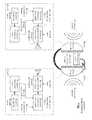
- FIG. 2is a schematic block diagram of an embodiment of an active noise reduction (ANR) circuit 24 that includes an ANR microphone circuit 50 , a first filter 52 , a summing module 54 , a second filter 56 , an operational amplifier 58 , a feedback filter 60 , and a third filter.
- the ANR microphone circuitreceives the output audio signal 38 via the acoustic vibrations produced by the speaker and generates the ANR signal therefrom.
- the ANR microphone circuitincludes a microphone, a biasing circuit, an adjustable gain stage, and may further include filtering.
- the microphonemay be an inverting microphone that includes a standard electrical condenser and a built-in inverting pre-amplifier.
- the first filter 52which may include a blocking capacitor, high pass filters the hearing compensated audio signal 34 to produce a filtered hearing compensated audio signal. In addition to blocking a DC component of the hearing compensated audio signal 34 , the first filter 52 sets the signal level to be injected into the summing module 54 .
- the summing module 54sum the filtered hearing compensated audio signal and the ANR signal 36 to produce a summed audio signal.
- the summing modulemay be implemented as a three-wire connection.
- the summing moduleis an analog adder. Note that the summing module 54 may include a resistor to provide power to the microphone circuit 50 .
- the second filter 56filter the summed audio signal to produce a filtered summed audio signal.
- the second filter 56includes phase-controlled high-pass filter components and may further include phase-controlled low-pass filter components.
- a resistor-capacitor circuitmay establish the corner frequency for the high pass function.
- a resistor-capacitor circuitmay establish the corner frequency for the low pass function. Phase control is used to ensures that the second filter 56 does not phase shift the summed signal by more than 90 degrees.
- the third filter 62high pass filters the hearing compensated audio signal 34 to produce a high pass filtered hearing compensated audio signal.
- the corner frequency of the third filteris set near the top of the ANR range (e.g., 1 KHz to 2 KHz) to extended the high frequency audio response above the ANR range and functions to compensate for the roll-off of the feedback filter 60 .
- the feedback filter 60filters the output audio signal 38 to produce a feedback signal and assists in controlling the phase shift of the amplifier 58 .
- the feedback filter 60includes phase controlled low pass and high pass components that are set to the voltage gain of the amplifier 58 .
- the operational amplifier 58includes an inverting input, a non-inverting input, and an output, wherein the non-inverting input receives the summed audio signal, the inverting input receives the feedback signal and the high pass filtered hearing compensated audio signal, and the output outputs the output audio signal 38 to one or more speakers.
- FIG. 3is a schematic block diagram of another embodiment of an active noise reduction circuit 24 of FIG. 2 plus a fourth filter 64 , a signal detector 66 , and a comparison circuit 68 .
- the fourth filter 64high pass filters the output audio signal 38 to produce a high pass filtered output audio signal.
- the fourth filter 64includes passive and/or active components to produce a high pass filter that has a corner frequency above a normal voice range (e.g., >2 KHz) to detect undesired feedback in the output signal 38 .
- the signal detector 66converts the high pass filtered output audio signal into a proportional direct current (DC) signal.
- the signal detector 66may be a comparator with hysteresis to avoid false triggering from transients of the output signal 38 .
- the comparison circuit 68which may be a latch, disables the ANR circuit 24 when the proportional DC signal compares unfavorably to a high frequency feedback threshold voltage. This prevents the feedback from causing a squeal in the output signal that is irritating, if not harmful, the user of the system 10 .
- the control module 16can reset the ANR circuit if it is disabled in this manner.
- the ANR circuit 24produces an inverse output proportional to the ANR microphone signal to effect cancellation of ambient acoustic noise.
- the amount of noise reductionis proportional to the amplifier gain, and to the gain of the speaker-microphone combination. For example, if at a certain frequency the speaker-microphone gain is ⁇ 0.2 and the amplifier gain (including filter loss) is +50, then the overall system gain will be ⁇ 10, thus there will be 20 db of noise reduction.
- a 20 millivolt microphone signalproduces a 1 volt output on the speaker, which normally would produce a 200 mV signal on the microphone (gain of ⁇ 0.2) but because it is combining with the noise being cancelled with 20 db of noise reduction (10 times voltage ratio), it is reduced to 20 mV.
- the systemwill output a counter signal to the speaker that drives the microphone signal level to 20 mV.
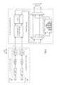
- FIG. 4is a schematic block diagram of an embodiment of a microphone circuit 18 and an audio processing module 20 .
- the microphone circuit 18includes one or more first microphones 80 , one or more second microphones 82 , and compensation circuitry 84 .
- the audio processing module 20includes a multiple band compression module 90 , a noise reduction module 92 , and a selectable multiple band equalizer module 88 .
- the combination of the compression module 90 , the noise reduction module 92 , and the equalizer module 88perform a hear-through function 86 .
- the microphones 80 and 82receive the acoustic vibrations 26 to produce analog signals representative of the acoustic vibrations.
- the positioning of the microphones 80 and 82 within the left or right ear unitis such that they form a diversity microphone structure (e.g., are physically distributed such that the microphones 80 and 82 will receive the acoustic vibrations at different times depending on the position of the source of the vibrations relative to the microphones).
- the microphone compensation circuitry 84compensates the first and second analog audio signals to produce the audio signal 28 .
- the compensation circuitry 84may include one or more of an analog gain stage, a filtering stage (e.g., low pass, high pass, or band pass), and/or a level shift stage (adjust DC and/or AC level of the audio signal 28 ).
- the audio processing module 20receives the audio signal 28 and performs a hear-through function thereon.
- the hear-through functionincludes one or more of a multiple band compression, noise reduction, and a multiple band equalization.
- the audio frequency spectrume.g., 0-20 KHz
- the audio frequency spectrummay be equally divided into 20 1-KHz bands.
- the 0-4 KHz portion of the frequency rangemay be divided into a 100 Hz to 1 KHz bands and the remainder of the range divided into 1-4 bands.
- each frequency bandmay have an individually set amplitude threshold to which the signal component in the frequency band is compressed.
- the multiple frequency band compression 90may be done in the analog domain or the digital domain. If done in the digital domain, the audio signal 28 is converted into a digital signal prior to compression.
- the noise reduction module 92functions to isolate the undesired signal component of the audio signal 28 from the undesired signal component. In general, this may be done in the analog domain by identifying the undesired signal component, generating an inversion thereof, and mixing it with the audio signal to yield the desired signal component. If done in the digital domain, the noise reduction module 92 separates the desired signal component from the undesired signal component. It then attenuates the undesired signal component and passes the desired signal component substantially unattenuated. This may be done in a variety of ways. For example, the noise reduction module 92 may analyze the digital signal to detect the undesired signal component (e.g., noise, transients, etc.) using one or more matched filters, audio correlation, audio codebook look ups, etc.
- the undesired signal componente.g., noise, transients, etc.
- the multiple band equalization module 88may be by-passed via the multiplexers, or equivalent hardware and/or software, or engaged. If engaged, the multiple band equalizer module 88 adjusts amplitudes of various frequency bands to produce the representative 30 of the audio signal 28 . Note that the equalization may be done in the analog domain or in the digital domain.
- FIG. 5is a schematic block diagram of an embodiment of an audio processing module 20 and/or a digital audio processing module 22 performing one or more of digital multiple band compression 96 , digital noise reduction 98 , digital multiple band equalization 94 , and digital multi-hearing compensation 100 . These digital functions may be done in conjunction with the corresponding functions previously discussed with reference to FIG. 4 or in place of them.
- the digital multi-hearing compensation module 100provides various modes for modifying the audio signal 28 to produce the hearing compensated audio signal 34 .
- the digital multi-hearing compensation module 100may be a separate module as shown that adjusts the signal it receives in accordance with one of a plurality of hearing compensation data (e.g., hearing aid profiles).
- the digital multi-hearing module 100may not be in the path of converting the audio signal 28 into the hearing compensated audio signal 34 , but a control module that provides inputs to the digital multiple band compression module 96 and/or to the digital multiple band equalizer module 94 such that at least one of these modules 94 and 96 performs the hearing compensation of the audio signal.
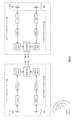
- FIG. 6is a schematic block diagram of an embodiment of a microphone circuit 18 that includes the one or more first microphones 80 , the one or more second microphones 82 , and the compensation circuitry 84 in each of the left and right ear units 12 and 14 .
- the compensation circuitry 84further includes a three-dimensional (3D) effect module.
- the 3D effect modulecompensates the first and second analog audio signals based on a natural cardioid pattern to produce the left and right audio signal having three-dimensional characteristics. For example, if an audio source is positioned in two-dimensional space closer to the left microphone circuit 18 than the right one and, on the left side, is closer to the second microphone 82 than the first microphone 80 , then each of the microphones will receive the vibrations of the audio source at different times. By maintaining the temporal information of the audio input signals, a three-dimensional representation of the audio signal is provided via the 3D effect module to the audio processing module 20 . Note that the 3D effect module may be implemented using analog circuitry or digital circuitry to produce the 3D effect, or a surround sound effect.
- FIG. 7is a schematic block diagram of an embodiment of a microphone circuit 18 that includes the one or more first microphones 80 , the one or more second microphones 82 , and the compensation circuitry 84 in each of the left and right ear units 12 and 14 .
- the compensation circuitry 84further includes a transition detect module.
- the transition detect modulemay be in the audio processing module 20 .
- the transition detection modulefunctions to detect large transients (e.g., detect loud sudden noises such as a gun shot, etc.).
- the transient detect modulemay be coupled to the microphones as shown, or may be coupled to after any functional block of the compensation circuitry.
- a transition detect module in either the left or right ear unitdetects a large transient, it provides a signal to both the left and right multiple band compression modules 90 such that the loud sudden noise is suppressed in both ears.
- both sides' compression modules 90By activating both sides' compression modules 90 , the three-dimensional information of the noise is preserved.
- FIG. 8is a schematic block diagram of another embodiment of a hearing enhancement system 10 that includes the circuit 15 in each of the left and right ear units 12 and 14 .
- the system 10further includes a stereo output 110 , an auxiliary input 112 , and an auxiliary output 120 .
- the circuit 15includes the microphone circuit 18 , the audio processing module 20 , the digital audio processing module 22 , the ANR circuit 24 , a second microphone circuit 114 , and a processing module 116 .
- the processing module 116may be a separate processing module or a shared processing module with the digital audio processing module 22 .
- the auxiliary input 112may be an audio jack, a two or three-wire connection (e.g., I 2 C), or other type of connector that is capable of receiving an auxiliary audio signal from a communication device.
- the control unit 16may receive a signal from a two-way communication device and provide it via the auxiliary input 112 to the left and right ear units 12 and 14 .
- the audio processing module 20mixes the audio signal 28 with the auxiliary audio signal to produce a mixed audio signal.
- the mixed audio signalis then processed as previously discussed with the processing of the audio signal 28 to produce the representation 30
- the stereo output 110may include a left and right audio multiplexer and a connector.
- the stereo output 110which may be within one of the left or right ear units 12 or 14 , or within the control module 16 , outputs a representation of the left and right output signals 38 .
- the representationmay be selected by the multiplexer and may include one or more of the representation 30 (e.g., including the signal from the auxiliary input 112 and/or the representation of the audio signal 28 ), the hearing compensated audio signal 34 , and/or the output audio signal 38 .
- the stereo output 110includes a female audio jack for connection to a male audio plug affiliated with a set of ear bud speakers.
- the stereo output 110may route the hearing compensated audio signal 34 to the audio jack.
- the usermay wear the ear bud headphones underneath the left and right ear units to further improve performance of the system 10 . This may be especially useful in extremely loud and sudden noise situations (e.g., detonation of an explosive) where the shock wave of the noise temporarily lifts the ear cups off the user's ears.
- the control module 16may control the multiplexer selection based on an operational mode. For example, the control module 16 may select the representation 30 where the representation 30 only includes the auxiliary audio signal from the communication device when the mode is to listen exclusively to the communication device (e.g., for high priority radio traffic).
- the second microphone circuit 114receives spoken audible sounds from the user of the system 10 and generates a voice signal therefrom.
- the second microphone circuit 114includes one or more microphones and microphone compensation circuitry (e.g., circuitry 84 of FIG. 4 ).
- the one or more microphonesare physically located on the left and/or right ear units 12 and/or 14 to easily receive utterances from the user.
- the processing module 116converts the voice signal into a digital audio signal 188 . Such a conversion includes one or more of analog to digital conversion, audio processing (e.g., MPEG encoding), audio compression, etc.
- the processing module 116provides the digital audio signal 118 to the auxiliary output 120 .
- the terms “substantially” and “approximately”provides an industry-accepted tolerance for its corresponding term and/or relativity between items. Such an industry-accepted tolerance ranges from less than one percent to fifty percent and corresponds to, but is not limited to, component values, integrated circuit process variations, temperature variations, rise and fall times, and/or thermal noise. Such relativity between items ranges from a difference of a few percent to magnitude differences.
- the term(s) “operably coupled to”, “coupled to”, and/or “coupling”includes direct coupling between items and/or indirect coupling between items via an intervening item (e.g., an item includes, but is not limited to, a component, an element, a circuit, and/or a module) where, for indirect coupling, the intervening item does not modify the information of a signal but may adjust its current level, voltage level, and/or power level.
- inferred couplingi.e., where one element is coupled to another element by inference
- the term “operable to” or “operably coupled to”indicates that an item includes one or more of power connections, input(s), output(s), etc., to perform, when activated, one or more its corresponding functions and may further include inferred coupling to one or more other items.
- the term “associated with”,includes direct and/or indirect coupling of separate items and/or one item being embedded within another item.
- the term “compares favorably”,indicates that a comparison between two or more items, signals, etc., provides a desired relationship. For example, when the desired relationship is that signal 1 has a greater magnitude than signal 2 , a favorable comparison may be achieved when the magnitude of signal 1 is greater than that of signal 2 or when the magnitude of signal 2 is less than that of signal 1 .
- transistors in the above described figure(s)is/are shown as field effect transistors (FETs), as one of ordinary skill in the art will appreciate, the transistors may be implemented using any type of transistor structure including, but not limited to, bipolar, metal oxide semiconductor field effect transistors (MOSFET), N-well transistors, P-well transistors, enhancement mode, depletion mode, and zero voltage threshold (VT) transistors.
- FETsfield effect transistors
- MOSFETmetal oxide semiconductor field effect transistors
- N-well transistorsN-well transistors
- P-well transistorsP-well transistors
- enhancement modeenhancement mode
- depletion modedepletion mode
- VTzero voltage threshold
Landscapes
- Physics & Mathematics (AREA)
- Engineering & Computer Science (AREA)
- Acoustics & Sound (AREA)
- Signal Processing (AREA)
- Soundproofing, Sound Blocking, And Sound Damping (AREA)
Abstract
Description
Claims (21)
Priority Applications (1)
| Application Number | Priority Date | Filing Date | Title |
|---|---|---|---|
| US12/551,805US8416959B2 (en) | 2009-08-17 | 2009-09-01 | Hearing enhancement system and components thereof |
Applications Claiming Priority (2)
| Application Number | Priority Date | Filing Date | Title |
|---|---|---|---|
| US23459809P | 2009-08-17 | 2009-08-17 | |
| US12/551,805US8416959B2 (en) | 2009-08-17 | 2009-09-01 | Hearing enhancement system and components thereof |
Publications (2)
| Publication Number | Publication Date |
|---|---|
| US20110038496A1 US20110038496A1 (en) | 2011-02-17 |
| US8416959B2true US8416959B2 (en) | 2013-04-09 |
Family
ID=43588614
Family Applications (1)
| Application Number | Title | Priority Date | Filing Date |
|---|---|---|---|
| US12/551,805Expired - Fee RelatedUS8416959B2 (en) | 2009-08-17 | 2009-09-01 | Hearing enhancement system and components thereof |
Country Status (1)
| Country | Link |
|---|---|
| US (1) | US8416959B2 (en) |
Cited By (23)
| Publication number | Priority date | Publication date | Assignee | Title |
|---|---|---|---|---|
| US20080146890A1 (en)* | 2006-12-19 | 2008-06-19 | Valencell, Inc. | Telemetric apparatus for health and environmental monitoring |
| US20120020493A1 (en)* | 2010-07-21 | 2012-01-26 | Michaelis Andre | In-ear earphone |
| US20130252675A1 (en)* | 2010-06-04 | 2013-09-26 | Apple Inc. | Active noise cancellation decisions in a portable audio device |
| US8989830B2 (en) | 2009-02-25 | 2015-03-24 | Valencell, Inc. | Wearable light-guiding devices for physiological monitoring |
| US9044180B2 (en) | 2007-10-25 | 2015-06-02 | Valencell, Inc. | Noninvasive physiological analysis using excitation-sensor modules and related devices and methods |
| US9099077B2 (en) | 2010-06-04 | 2015-08-04 | Apple Inc. | Active noise cancellation decisions using a degraded reference |
| US9289175B2 (en) | 2009-02-25 | 2016-03-22 | Valencell, Inc. | Light-guiding devices and monitoring devices incorporating same |
| US9427191B2 (en) | 2011-07-25 | 2016-08-30 | Valencell, Inc. | Apparatus and methods for estimating time-state physiological parameters |
| US9538921B2 (en) | 2014-07-30 | 2017-01-10 | Valencell, Inc. | Physiological monitoring devices with adjustable signal analysis and interrogation power and monitoring methods using same |
| US9750462B2 (en) | 2009-02-25 | 2017-09-05 | Valencell, Inc. | Monitoring apparatus and methods for measuring physiological and/or environmental conditions |
| US9779752B2 (en) | 2014-10-31 | 2017-10-03 | At&T Intellectual Property I, L.P. | Acoustic enhancement by leveraging metadata to mitigate the impact of noisy environments |
| US9794653B2 (en) | 2014-09-27 | 2017-10-17 | Valencell, Inc. | Methods and apparatus for improving signal quality in wearable biometric monitoring devices |
| US9801552B2 (en) | 2011-08-02 | 2017-10-31 | Valencell, Inc. | Systems and methods for variable filter adjustment by heart rate metric feedback |
| US10015582B2 (en) | 2014-08-06 | 2018-07-03 | Valencell, Inc. | Earbud monitoring devices |
| US10076253B2 (en) | 2013-01-28 | 2018-09-18 | Valencell, Inc. | Physiological monitoring devices having sensing elements decoupled from body motion |
| US10258243B2 (en) | 2006-12-19 | 2019-04-16 | Valencell, Inc. | Apparatus, systems, and methods for measuring environmental exposure and physiological response thereto |
| US10484792B2 (en) | 2018-02-16 | 2019-11-19 | Skullcandy, Inc. | Headphone with noise cancellation of acoustic noise from tactile vibration driver |
| US10547947B2 (en) | 2016-05-18 | 2020-01-28 | Qualcomm Incorporated | Device for generating audio output |
| US10610158B2 (en) | 2015-10-23 | 2020-04-07 | Valencell, Inc. | Physiological monitoring devices and methods that identify subject activity type |
| US10827979B2 (en) | 2011-01-27 | 2020-11-10 | Valencell, Inc. | Wearable monitoring device |
| US10872592B2 (en) | 2017-12-15 | 2020-12-22 | Skullcandy, Inc. | Noise-canceling headphones including multiple vibration members and related methods |
| US10945618B2 (en) | 2015-10-23 | 2021-03-16 | Valencell, Inc. | Physiological monitoring devices and methods for noise reduction in physiological signals based on subject activity type |
| US10966662B2 (en) | 2016-07-08 | 2021-04-06 | Valencell, Inc. | Motion-dependent averaging for physiological metric estimating systems and methods |
Families Citing this family (29)
| Publication number | Priority date | Publication date | Assignee | Title |
|---|---|---|---|---|
| US20090175463A1 (en)* | 2008-01-08 | 2009-07-09 | Fortune Grand Technology Inc. | Noise-canceling sound playing structure |
| US8553900B2 (en)* | 2010-05-14 | 2013-10-08 | Creative Technology Ltd | Noise reduction circuit with monitoring functionality |
| JP5919686B2 (en)* | 2011-08-31 | 2016-05-18 | ソニー株式会社 | Sound playback device |
| JP6019553B2 (en)* | 2011-08-31 | 2016-11-02 | ソニー株式会社 | Earphone device |
| US9020160B2 (en)* | 2012-11-02 | 2015-04-28 | Bose Corporation | Reducing occlusion effect in ANR headphones |
| US8798283B2 (en)* | 2012-11-02 | 2014-08-05 | Bose Corporation | Providing ambient naturalness in ANR headphones |
| US20140126733A1 (en)* | 2012-11-02 | 2014-05-08 | Daniel M. Gauger, Jr. | User Interface for ANR Headphones with Active Hear-Through |
| US20140192994A1 (en)* | 2013-01-04 | 2014-07-10 | Roger Chen | Noise Cancelling Headphone |
| CN103945293A (en)* | 2013-01-22 | 2014-07-23 | 深圳富泰宏精密工业有限公司 | Noise reduction system, and earphone and portable electronic device having the noise reduction system |
| US9118987B2 (en)* | 2013-03-12 | 2015-08-25 | Bose Corporation | Motor vehicle active noise reduction |
| US11140502B2 (en)* | 2013-03-15 | 2021-10-05 | Jawbone Innovations, Llc | Filter selection for delivering spatial audio |
| EP3005344A4 (en) | 2013-05-31 | 2017-02-22 | Nokia Technologies OY | An audio scene apparatus |
| US9084050B2 (en)* | 2013-07-12 | 2015-07-14 | Elwha Llc | Systems and methods for remapping an audio range to a human perceivable range |
| DK3051844T3 (en)* | 2015-01-30 | 2018-01-29 | Oticon As | Binaural hearing system |
| US9565491B2 (en)* | 2015-06-01 | 2017-02-07 | Doppler Labs, Inc. | Real-time audio processing of ambient sound |
| JP6904255B2 (en)* | 2015-10-19 | 2021-07-14 | ソニーグループ株式会社 | Information processing system and program |
| EP3182406B1 (en) | 2015-12-16 | 2020-04-01 | Harman Becker Automotive Systems GmbH | Sound reproduction with active noise control in a helmet |
| JP6124203B1 (en)* | 2016-05-13 | 2017-05-10 | 株式会社ボーダレス | Acoustic signal processing device and helmet equipped with the same |
| KR101756674B1 (en)* | 2016-05-27 | 2017-07-25 | 주식회사 이엠텍 | Active noise reduction headset device with hearing aid features |
| USD835076S1 (en) | 2016-11-01 | 2018-12-04 | Safariland, Llc | Speaker and microphone housing |
| US9894452B1 (en) | 2017-02-24 | 2018-02-13 | Bose Corporation | Off-head detection of in-ear headset |
| US10595114B2 (en) | 2017-07-31 | 2020-03-17 | Bose Corporation | Adaptive headphone system |
| EP3456299B1 (en)* | 2017-09-19 | 2021-11-03 | Safariland, LLC | Multi profile hearing protection headset |
| CN110300344B (en)* | 2019-03-25 | 2024-06-14 | 深圳市增长点科技有限公司 | Self-adaptive noise reduction earphone |
| US10964304B2 (en) | 2019-06-20 | 2021-03-30 | Bose Corporation | Instability mitigation in an active noise reduction (ANR) system having a hear-through mode |
| SE545513C2 (en)* | 2021-05-12 | 2023-10-03 | Audiodo Ab Publ | Voice optimization in noisy environments |
| TWM635174U (en)* | 2022-04-01 | 2022-12-11 | 弘憶國際股份有限公司 | Hearing compensation device and hearing apparatus with the hearing compensation device |
| US11985481B2 (en) | 2022-04-01 | 2024-05-14 | Rehear Audiology Company Ltd. | Hearing compensation device and hearing compensation method |
| CN116132875B (en)* | 2023-04-17 | 2023-07-04 | 深圳市九音科技有限公司 | A multi-mode intelligent control method, system and storage medium for hearing aid earphones |
Citations (8)
| Publication number | Priority date | Publication date | Assignee | Title |
|---|---|---|---|---|
| US3683130A (en)* | 1967-10-03 | 1972-08-08 | Kahn Res Lab | Headset with circuit control |
| US4455675A (en) | 1982-04-28 | 1984-06-19 | Bose Corporation | Headphoning |
| US4479239A (en)* | 1983-03-28 | 1984-10-23 | Silver Creek Nurseries, Inc. | Sound detecting device |
| US5675658A (en) | 1995-07-27 | 1997-10-07 | Brittain; Thomas Paige | Active noise reduction headset |
| US5732143A (en) | 1992-10-29 | 1998-03-24 | Andrea Electronics Corp. | Noise cancellation apparatus |
| US20030198357A1 (en)* | 2001-08-07 | 2003-10-23 | Todd Schneider | Sound intelligibility enhancement using a psychoacoustic model and an oversampled filterbank |
| US20050276421A1 (en) | 2004-06-15 | 2005-12-15 | Bose Corporation | Noise reduction headset |
| US20080199023A1 (en)* | 2005-05-27 | 2008-08-21 | Oy Martin Kantola Consulting Ltd. | Assembly, System and Method for Acoustic Transducers |
Family Cites Families (1)
| Publication number | Priority date | Publication date | Assignee | Title |
|---|---|---|---|---|
| JPH0836281A (en)* | 1994-05-18 | 1996-02-06 | Bridgestone Corp | Paper feed roll and paper feeder |
- 2009
- 2009-09-01USUS12/551,805patent/US8416959B2/ennot_activeExpired - Fee Related
Patent Citations (9)
| Publication number | Priority date | Publication date | Assignee | Title |
|---|---|---|---|---|
| US3683130A (en)* | 1967-10-03 | 1972-08-08 | Kahn Res Lab | Headset with circuit control |
| US4455675A (en) | 1982-04-28 | 1984-06-19 | Bose Corporation | Headphoning |
| US4479239A (en)* | 1983-03-28 | 1984-10-23 | Silver Creek Nurseries, Inc. | Sound detecting device |
| US5732143A (en) | 1992-10-29 | 1998-03-24 | Andrea Electronics Corp. | Noise cancellation apparatus |
| US6061456A (en) | 1992-10-29 | 2000-05-09 | Andrea Electronics Corporation | Noise cancellation apparatus |
| US5675658A (en) | 1995-07-27 | 1997-10-07 | Brittain; Thomas Paige | Active noise reduction headset |
| US20030198357A1 (en)* | 2001-08-07 | 2003-10-23 | Todd Schneider | Sound intelligibility enhancement using a psychoacoustic model and an oversampled filterbank |
| US20050276421A1 (en) | 2004-06-15 | 2005-12-15 | Bose Corporation | Noise reduction headset |
| US20080199023A1 (en)* | 2005-05-27 | 2008-08-21 | Oy Martin Kantola Consulting Ltd. | Assembly, System and Method for Acoustic Transducers |
Non-Patent Citations (1)
| Title |
|---|
| Gentex, "Active Noise Reduction (ANR) Flat Module Description," Transaero, Inc., FSC No. 27541, Jun. 1999, (1 Pg.). |
Cited By (95)
| Publication number | Priority date | Publication date | Assignee | Title |
|---|---|---|---|---|
| US10716481B2 (en) | 2006-12-19 | 2020-07-21 | Valencell, Inc. | Apparatus, systems and methods for monitoring and evaluating cardiopulmonary functioning |
| US11109767B2 (en) | 2006-12-19 | 2021-09-07 | Valencell, Inc. | Apparatus, systems and methods for obtaining cleaner physiological information signals |
| US11272848B2 (en) | 2006-12-19 | 2022-03-15 | Valencell, Inc. | Wearable apparatus for multiple types of physiological and/or environmental monitoring |
| US8652040B2 (en)* | 2006-12-19 | 2014-02-18 | Valencell, Inc. | Telemetric apparatus for health and environmental monitoring |
| US10987005B2 (en) | 2006-12-19 | 2021-04-27 | Valencell, Inc. | Systems and methods for presenting personal health information |
| US11272849B2 (en) | 2006-12-19 | 2022-03-15 | Valencell, Inc. | Wearable apparatus |
| US11412938B2 (en) | 2006-12-19 | 2022-08-16 | Valencell, Inc. | Physiological monitoring apparatus and networks |
| US10595730B2 (en) | 2006-12-19 | 2020-03-24 | Valencell, Inc. | Physiological monitoring methods |
| US11295856B2 (en) | 2006-12-19 | 2022-04-05 | Valencell, Inc. | Apparatus, systems, and methods for measuring environmental exposure and physiological response thereto |
| US11083378B2 (en) | 2006-12-19 | 2021-08-10 | Valencell, Inc. | Wearable apparatus having integrated physiological and/or environmental sensors |
| US11395595B2 (en) | 2006-12-19 | 2022-07-26 | Valencell, Inc. | Apparatus, systems and methods for monitoring and evaluating cardiopulmonary functioning |
| US11324407B2 (en) | 2006-12-19 | 2022-05-10 | Valencell, Inc. | Methods and apparatus for physiological and environmental monitoring with optical and footstep sensors |
| US11350831B2 (en) | 2006-12-19 | 2022-06-07 | Valencell, Inc. | Physiological monitoring apparatus |
| US10413197B2 (en) | 2006-12-19 | 2019-09-17 | Valencell, Inc. | Apparatus, systems and methods for obtaining cleaner physiological information signals |
| US10258243B2 (en) | 2006-12-19 | 2019-04-16 | Valencell, Inc. | Apparatus, systems, and methods for measuring environmental exposure and physiological response thereto |
| US11000190B2 (en) | 2006-12-19 | 2021-05-11 | Valencell, Inc. | Apparatus, systems and methods for obtaining cleaner physiological information signals |
| US20080146890A1 (en)* | 2006-12-19 | 2008-06-19 | Valencell, Inc. | Telemetric apparatus for health and environmental monitoring |
| US11399724B2 (en) | 2006-12-19 | 2022-08-02 | Valencell, Inc. | Earpiece monitor |
| US9044180B2 (en) | 2007-10-25 | 2015-06-02 | Valencell, Inc. | Noninvasive physiological analysis using excitation-sensor modules and related devices and methods |
| US9808204B2 (en) | 2007-10-25 | 2017-11-07 | Valencell, Inc. | Noninvasive physiological analysis using excitation-sensor modules and related devices and methods |
| US9314167B2 (en) | 2009-02-25 | 2016-04-19 | Valencell, Inc. | Methods for generating data output containing physiological and motion-related information |
| US11160460B2 (en) | 2009-02-25 | 2021-11-02 | Valencell, Inc. | Physiological monitoring methods |
| US11026588B2 (en) | 2009-02-25 | 2021-06-08 | Valencell, Inc. | Methods and apparatus for detecting motion noise and for removing motion noise from physiological signals |
| US9955919B2 (en) | 2009-02-25 | 2018-05-01 | Valencell, Inc. | Light-guiding devices and monitoring devices incorporating same |
| US11589812B2 (en) | 2009-02-25 | 2023-02-28 | Valencell, Inc. | Wearable devices for physiological monitoring |
| US9750462B2 (en) | 2009-02-25 | 2017-09-05 | Valencell, Inc. | Monitoring apparatus and methods for measuring physiological and/or environmental conditions |
| US10076282B2 (en) | 2009-02-25 | 2018-09-18 | Valencell, Inc. | Wearable monitoring devices having sensors and light guides |
| US11660006B2 (en) | 2009-02-25 | 2023-05-30 | Valencell, Inc. | Wearable monitoring devices with passive and active filtering |
| US10842389B2 (en) | 2009-02-25 | 2020-11-24 | Valencell, Inc. | Wearable audio devices |
| US10898083B2 (en) | 2009-02-25 | 2021-01-26 | Valencell, Inc. | Wearable monitoring devices with passive and active filtering |
| US10842387B2 (en) | 2009-02-25 | 2020-11-24 | Valencell, Inc. | Apparatus for assessing physiological conditions |
| US10092245B2 (en) | 2009-02-25 | 2018-10-09 | Valencell, Inc. | Methods and apparatus for detecting motion noise and for removing motion noise from physiological signals |
| US10448840B2 (en) | 2009-02-25 | 2019-10-22 | Valencell, Inc. | Apparatus for generating data output containing physiological and motion-related information |
| US11471103B2 (en) | 2009-02-25 | 2022-10-18 | Valencell, Inc. | Ear-worn devices for physiological monitoring |
| US9301696B2 (en) | 2009-02-25 | 2016-04-05 | Valencell, Inc. | Earbud covers |
| US9289175B2 (en) | 2009-02-25 | 2016-03-22 | Valencell, Inc. | Light-guiding devices and monitoring devices incorporating same |
| US9289135B2 (en) | 2009-02-25 | 2016-03-22 | Valencell, Inc. | Physiological monitoring methods and apparatus |
| US9131312B2 (en) | 2009-02-25 | 2015-09-08 | Valencell, Inc. | Physiological monitoring methods |
| US10542893B2 (en) | 2009-02-25 | 2020-01-28 | Valencell, Inc. | Form-fitted monitoring apparatus for health and environmental monitoring |
| US10750954B2 (en) | 2009-02-25 | 2020-08-25 | Valencell, Inc. | Wearable devices with flexible optical emitters and/or optical detectors |
| US8989830B2 (en) | 2009-02-25 | 2015-03-24 | Valencell, Inc. | Wearable light-guiding devices for physiological monitoring |
| US10973415B2 (en) | 2009-02-25 | 2021-04-13 | Valencell, Inc. | Form-fitted monitoring apparatus for health and environmental monitoring |
| US10716480B2 (en) | 2009-02-25 | 2020-07-21 | Valencell, Inc. | Hearing aid earpiece covers |
| US20130252675A1 (en)* | 2010-06-04 | 2013-09-26 | Apple Inc. | Active noise cancellation decisions in a portable audio device |
| US9099077B2 (en) | 2010-06-04 | 2015-08-04 | Apple Inc. | Active noise cancellation decisions using a degraded reference |
| US9330654B2 (en)* | 2010-06-04 | 2016-05-03 | Apple Inc. | Active noise cancellation decisions in a portable audio device |
| US20120020493A1 (en)* | 2010-07-21 | 2012-01-26 | Michaelis Andre | In-ear earphone |
| US8891779B2 (en)* | 2010-07-21 | 2014-11-18 | Sennheiser Electronic Gmbh & Co. Kg | In-ear earphone |
| US11324445B2 (en) | 2011-01-27 | 2022-05-10 | Valencell, Inc. | Headsets with angled sensor modules |
| US10827979B2 (en) | 2011-01-27 | 2020-11-10 | Valencell, Inc. | Wearable monitoring device |
| US9788785B2 (en) | 2011-07-25 | 2017-10-17 | Valencell, Inc. | Apparatus and methods for estimating time-state physiological parameters |
| US9521962B2 (en) | 2011-07-25 | 2016-12-20 | Valencell, Inc. | Apparatus and methods for estimating time-state physiological parameters |
| US9427191B2 (en) | 2011-07-25 | 2016-08-30 | Valencell, Inc. | Apparatus and methods for estimating time-state physiological parameters |
| US10512403B2 (en) | 2011-08-02 | 2019-12-24 | Valencell, Inc. | Systems and methods for variable filter adjustment by heart rate metric feedback |
| US11375902B2 (en) | 2011-08-02 | 2022-07-05 | Valencell, Inc. | Systems and methods for variable filter adjustment by heart rate metric feedback |
| US9801552B2 (en) | 2011-08-02 | 2017-10-31 | Valencell, Inc. | Systems and methods for variable filter adjustment by heart rate metric feedback |
| US11266319B2 (en) | 2013-01-28 | 2022-03-08 | Valencell, Inc. | Physiological monitoring devices having sensing elements decoupled from body motion |
| US10856749B2 (en) | 2013-01-28 | 2020-12-08 | Valencell, Inc. | Physiological monitoring devices having sensing elements decoupled from body motion |
| US10076253B2 (en) | 2013-01-28 | 2018-09-18 | Valencell, Inc. | Physiological monitoring devices having sensing elements decoupled from body motion |
| US11684278B2 (en) | 2013-01-28 | 2023-06-27 | Yukka Magic Llc | Physiological monitoring devices having sensing elements decoupled from body motion |
| US12076126B2 (en) | 2013-01-28 | 2024-09-03 | Yukka Magic Llc | Physiological monitoring devices having sensing elements decoupled from body motion |
| US12193845B2 (en) | 2014-07-30 | 2025-01-14 | Yukka Magic Llc | Physiological monitoring devices and methods using optical sensors |
| US11337655B2 (en) | 2014-07-30 | 2022-05-24 | Valencell, Inc. | Physiological monitoring devices and methods using optical sensors |
| US10893835B2 (en) | 2014-07-30 | 2021-01-19 | Valencell, Inc. | Physiological monitoring devices with adjustable signal analysis and interrogation power and monitoring methods using same |
| US9538921B2 (en) | 2014-07-30 | 2017-01-10 | Valencell, Inc. | Physiological monitoring devices with adjustable signal analysis and interrogation power and monitoring methods using same |
| US11179108B2 (en) | 2014-07-30 | 2021-11-23 | Valencell, Inc. | Physiological monitoring devices and methods using optical sensors |
| US11185290B2 (en) | 2014-07-30 | 2021-11-30 | Valencell, Inc. | Physiological monitoring devices and methods using optical sensors |
| US11638561B2 (en) | 2014-07-30 | 2023-05-02 | Yukka Magic Llc | Physiological monitoring devices with adjustable signal analysis and interrogation power and monitoring methods using same |
| US11638560B2 (en) | 2014-07-30 | 2023-05-02 | Yukka Magic Llc | Physiological monitoring devices and methods using optical sensors |
| US11412988B2 (en) | 2014-07-30 | 2022-08-16 | Valencell, Inc. | Physiological monitoring devices and methods using optical sensors |
| US12274567B2 (en) | 2014-07-30 | 2025-04-15 | Yukka Magic Llc | Physiological monitoring devices and methods using optical sensors |
| US11330361B2 (en) | 2014-08-06 | 2022-05-10 | Valencell, Inc. | Hearing aid optical monitoring apparatus |
| US10623849B2 (en) | 2014-08-06 | 2020-04-14 | Valencell, Inc. | Optical monitoring apparatus and methods |
| US10536768B2 (en) | 2014-08-06 | 2020-01-14 | Valencell, Inc. | Optical physiological sensor modules with reduced signal noise |
| US11252498B2 (en) | 2014-08-06 | 2022-02-15 | Valencell, Inc. | Optical physiological monitoring devices |
| US11252499B2 (en) | 2014-08-06 | 2022-02-15 | Valencell, Inc. | Optical physiological monitoring devices |
| US10015582B2 (en) | 2014-08-06 | 2018-07-03 | Valencell, Inc. | Earbud monitoring devices |
| US10779062B2 (en) | 2014-09-27 | 2020-09-15 | Valencell, Inc. | Wearable biometric monitoring devices and methods for determining if wearable biometric monitoring devices are being worn |
| US10798471B2 (en) | 2014-09-27 | 2020-10-06 | Valencell, Inc. | Methods for improving signal quality in wearable biometric monitoring devices |
| US10382839B2 (en) | 2014-09-27 | 2019-08-13 | Valencell, Inc. | Methods for improving signal quality in wearable biometric monitoring devices |
| US9794653B2 (en) | 2014-09-27 | 2017-10-17 | Valencell, Inc. | Methods and apparatus for improving signal quality in wearable biometric monitoring devices |
| US10834483B2 (en) | 2014-09-27 | 2020-11-10 | Valencell, Inc. | Wearable biometric monitoring devices and methods for determining if wearable biometric monitoring devices are being worn |
| US10506310B2 (en) | 2014-09-27 | 2019-12-10 | Valencell, Inc. | Wearable biometric monitoring devices and methods for determining signal quality in wearable biometric monitoring devices |
| US10170133B2 (en) | 2014-10-31 | 2019-01-01 | At&T Intellectual Property I, L.P. | Acoustic enhancement by leveraging metadata to mitigate the impact of noisy environments |
| US9779752B2 (en) | 2014-10-31 | 2017-10-03 | At&T Intellectual Property I, L.P. | Acoustic enhancement by leveraging metadata to mitigate the impact of noisy environments |
| US10610158B2 (en) | 2015-10-23 | 2020-04-07 | Valencell, Inc. | Physiological monitoring devices and methods that identify subject activity type |
| US12285244B2 (en) | 2015-10-23 | 2025-04-29 | Yukka Magic Llc | Physiological monitoring devices and methods for noise reduction in physiological signals based on subject activity type |
| US10945618B2 (en) | 2015-10-23 | 2021-03-16 | Valencell, Inc. | Physiological monitoring devices and methods for noise reduction in physiological signals based on subject activity type |
| US10547947B2 (en) | 2016-05-18 | 2020-01-28 | Qualcomm Incorporated | Device for generating audio output |
| US10966662B2 (en) | 2016-07-08 | 2021-04-06 | Valencell, Inc. | Motion-dependent averaging for physiological metric estimating systems and methods |
| US11688382B2 (en) | 2017-12-15 | 2023-06-27 | Skullcandy, Inc. | Noise-canceling audio device including multiple vibration members |
| US10872592B2 (en) | 2017-12-15 | 2020-12-22 | Skullcandy, Inc. | Noise-canceling headphones including multiple vibration members and related methods |
| US11335313B2 (en) | 2017-12-15 | 2022-05-17 | Skullcandy, Inc. | Noise-canceling headphones including multiple vibration members and related methods |
| US11172302B2 (en) | 2018-02-16 | 2021-11-09 | Skullcandy, Inc. | Methods of using headphones with noise cancellation of acoustic noise from tactile vibration driver |
| US10484792B2 (en) | 2018-02-16 | 2019-11-19 | Skullcandy, Inc. | Headphone with noise cancellation of acoustic noise from tactile vibration driver |
Also Published As
| Publication number | Publication date |
|---|---|
| US20110038496A1 (en) | 2011-02-17 |
Similar Documents
| Publication | Publication Date | Title |
|---|---|---|
| US8416959B2 (en) | Hearing enhancement system and components thereof | |
| US10748549B2 (en) | Audio signal processing for noise reduction | |
| US10096312B2 (en) | Noise cancellation system | |
| EP3704688B1 (en) | Compressive hear-through in personal acoustic devices | |
| US10075783B2 (en) | Acoustically summed reference microphone for active noise control | |
| US10341759B2 (en) | System and method of wind and noise reduction for a headphone | |
| US8964997B2 (en) | Adapted audio masking | |
| CN101091412B (en) | Apparatus and method for sound enhancement | |
| JP2019537367A (en) | On / off head detection of personal acoustic devices using earpiece microphones | |
| US20200030151A1 (en) | Adaptive electronic hearing protection device | |
| US10424287B2 (en) | Active noise-control device | |
| CN104754436B (en) | Active noise reduction method and noise reduction earphone | |
| CN105100990A (en) | Audio headset with active noise control ANC with prevention of effects of saturation of microphone signal feedback | |
| JP2015204627A (en) | Anc active noise control audio headset reducing electrical hiss | |
| CN109348327B (en) | Active noise reduction system | |
| CN112954530B (en) | Earphone noise reduction method, device and system and wireless earphone | |
| US20130343557A1 (en) | Headphone for active noise suppression | |
| US9516431B2 (en) | Spatial enhancement mode for hearing aids | |
| EP3155826B1 (en) | Self-voice feedback in communications headsets | |
| CN206713027U (en) | Denoising device and earphone | |
| TW202002673A (en) | headset | |
| US20040196984A1 (en) | Dynamic noise suppression voice communication device | |
| EP1689210B1 (en) | Hearing device | |
| CN108781318A (en) | Feedback whistle management in adaptive noise cancel- ation system | |
| CN110010117A (en) | Method and device for active noise reduction of speech |
Legal Events
| Date | Code | Title | Description |
|---|---|---|---|
| AS | Assignment | Owner name:SPEAR LABS, LLC, TENNESSEE Free format text:ASSIGNMENT OF ASSIGNORS INTEREST;ASSIGNORS:LOTT, DALE;NEWTON, WILLIAM TERRY;REEL/FRAME:023231/0050 Effective date:20090831 | |
| REMI | Maintenance fee reminder mailed | ||
| LAPS | Lapse for failure to pay maintenance fees | ||
| FP | Lapsed due to failure to pay maintenance fee | Effective date:20170409 | |
| FEPP | Fee payment procedure | Free format text:PETITION RELATED TO MAINTENANCE FEES FILED (ORIGINAL EVENT CODE: PMFP); ENTITY STATUS OF PATENT OWNER: SMALL ENTITY Free format text:PETITION RELATED TO MAINTENANCE FEES GRANTED (ORIGINAL EVENT CODE: PMFG); ENTITY STATUS OF PATENT OWNER: SMALL ENTITY Free format text:SURCHARGE, PETITION TO ACCEPT PYMT AFTER EXP, UNINTENTIONAL. (ORIGINAL EVENT CODE: M2558); ENTITY STATUS OF PATENT OWNER: SMALL ENTITY | |
| MAFP | Maintenance fee payment | Free format text:PAYMENT OF MAINTENANCE FEE, 4TH YR, SMALL ENTITY (ORIGINAL EVENT CODE: M2551); ENTITY STATUS OF PATENT OWNER: SMALL ENTITY Year of fee payment:4 | |
| PRDP | Patent reinstated due to the acceptance of a late maintenance fee | Effective date:20190211 | |
| STCF | Information on status: patent grant | Free format text:PATENTED CASE | |
| FEPP | Fee payment procedure | Free format text:MAINTENANCE FEE REMINDER MAILED (ORIGINAL EVENT CODE: REM.); ENTITY STATUS OF PATENT OWNER: SMALL ENTITY | |
| LAPS | Lapse for failure to pay maintenance fees | Free format text:PATENT EXPIRED FOR FAILURE TO PAY MAINTENANCE FEES (ORIGINAL EVENT CODE: EXP.); ENTITY STATUS OF PATENT OWNER: SMALL ENTITY | |
| STCH | Information on status: patent discontinuation | Free format text:PATENT EXPIRED DUE TO NONPAYMENT OF MAINTENANCE FEES UNDER 37 CFR 1.362 | |
| FP | Lapsed due to failure to pay maintenance fee | Effective date:20210409 |