US8414614B2 - Implant kit for supporting a spinal column - Google Patents
Implant kit for supporting a spinal columnDownload PDFInfo
- Publication number
- US8414614B2 US8414614B2US12/090,806US9080606AUS8414614B2US 8414614 B2US8414614 B2US 8414614B2US 9080606 AUS9080606 AUS 9080606AUS 8414614 B2US8414614 B2US 8414614B2
- Authority
- US
- United States
- Prior art keywords
- support element
- kit
- spinal
- cross
- section
- Prior art date
- Legal status (The legal status is an assumption and is not a legal conclusion. Google has not performed a legal analysis and makes no representation as to the accuracy of the status listed.)
- Active, expires
Links
- PMPVIKIVABFJJI-UHFFFAOYSA-NC1CCC1Chemical compoundC1CCC1PMPVIKIVABFJJI-UHFFFAOYSA-N0.000description4
Images


Classifications
- A—HUMAN NECESSITIES
- A61—MEDICAL OR VETERINARY SCIENCE; HYGIENE
- A61B—DIAGNOSIS; SURGERY; IDENTIFICATION
- A61B17/00—Surgical instruments, devices or methods
- A61B17/56—Surgical instruments or methods for treatment of bones or joints; Devices specially adapted therefor
- A61B17/58—Surgical instruments or methods for treatment of bones or joints; Devices specially adapted therefor for osteosynthesis, e.g. bone plates, screws or setting implements
- A61B17/68—Internal fixation devices, including fasteners and spinal fixators, even if a part thereof projects from the skin
- A61B17/70—Spinal positioners or stabilisers, e.g. stabilisers comprising fluid filler in an implant
- A61B17/7049—Connectors, not bearing on the vertebrae, for linking longitudinal elements together
- A61B17/705—Connectors, not bearing on the vertebrae, for linking longitudinal elements together for linking adjacent ends of longitudinal elements
- A—HUMAN NECESSITIES
- A61—MEDICAL OR VETERINARY SCIENCE; HYGIENE
- A61B—DIAGNOSIS; SURGERY; IDENTIFICATION
- A61B17/00—Surgical instruments, devices or methods
- A61B17/56—Surgical instruments or methods for treatment of bones or joints; Devices specially adapted therefor
- A61B17/58—Surgical instruments or methods for treatment of bones or joints; Devices specially adapted therefor for osteosynthesis, e.g. bone plates, screws or setting implements
- A61B17/68—Internal fixation devices, including fasteners and spinal fixators, even if a part thereof projects from the skin
- A61B17/70—Spinal positioners or stabilisers, e.g. stabilisers comprising fluid filler in an implant
- A61B17/7001—Screws or hooks combined with longitudinal elements which do not contact vertebrae
- A61B17/7002—Longitudinal elements, e.g. rods
- A61B17/701—Longitudinal elements with a non-circular, e.g. rectangular, cross-section
- A—HUMAN NECESSITIES
- A61—MEDICAL OR VETERINARY SCIENCE; HYGIENE
- A61B—DIAGNOSIS; SURGERY; IDENTIFICATION
- A61B17/00—Surgical instruments, devices or methods
- A61B17/56—Surgical instruments or methods for treatment of bones or joints; Devices specially adapted therefor
- A61B17/58—Surgical instruments or methods for treatment of bones or joints; Devices specially adapted therefor for osteosynthesis, e.g. bone plates, screws or setting implements
- A61B17/68—Internal fixation devices, including fasteners and spinal fixators, even if a part thereof projects from the skin
- A61B17/70—Spinal positioners or stabilisers, e.g. stabilisers comprising fluid filler in an implant
- A61B17/7001—Screws or hooks combined with longitudinal elements which do not contact vertebrae
- A61B17/7002—Longitudinal elements, e.g. rods
- A61B17/7011—Longitudinal element being non-straight, e.g. curved, angled or branched
- A—HUMAN NECESSITIES
- A61—MEDICAL OR VETERINARY SCIENCE; HYGIENE
- A61B—DIAGNOSIS; SURGERY; IDENTIFICATION
- A61B17/00—Surgical instruments, devices or methods
- A61B17/56—Surgical instruments or methods for treatment of bones or joints; Devices specially adapted therefor
- A61B17/58—Surgical instruments or methods for treatment of bones or joints; Devices specially adapted therefor for osteosynthesis, e.g. bone plates, screws or setting implements
- A61B17/68—Internal fixation devices, including fasteners and spinal fixators, even if a part thereof projects from the skin
- A61B17/70—Spinal positioners or stabilisers, e.g. stabilisers comprising fluid filler in an implant
- A61B17/7001—Screws or hooks combined with longitudinal elements which do not contact vertebrae
- A61B17/7002—Longitudinal elements, e.g. rods
- A61B17/7004—Longitudinal elements, e.g. rods with a cross-section which varies along its length
- A61B17/7005—Parts of the longitudinal elements, e.g. their ends, being specially adapted to fit in the screw or hook heads
- A—HUMAN NECESSITIES
- A61—MEDICAL OR VETERINARY SCIENCE; HYGIENE
- A61B—DIAGNOSIS; SURGERY; IDENTIFICATION
- A61B17/00—Surgical instruments, devices or methods
- A61B17/56—Surgical instruments or methods for treatment of bones or joints; Devices specially adapted therefor
- A61B17/58—Surgical instruments or methods for treatment of bones or joints; Devices specially adapted therefor for osteosynthesis, e.g. bone plates, screws or setting implements
- A61B17/68—Internal fixation devices, including fasteners and spinal fixators, even if a part thereof projects from the skin
- A61B17/70—Spinal positioners or stabilisers, e.g. stabilisers comprising fluid filler in an implant
- A61B17/7001—Screws or hooks combined with longitudinal elements which do not contact vertebrae
- A61B17/7002—Longitudinal elements, e.g. rods
- A61B17/7014—Longitudinal elements, e.g. rods with means for adjusting the distance between two screws or hooks
- A—HUMAN NECESSITIES
- A61—MEDICAL OR VETERINARY SCIENCE; HYGIENE
- A61B—DIAGNOSIS; SURGERY; IDENTIFICATION
- A61B17/00—Surgical instruments, devices or methods
- A61B17/56—Surgical instruments or methods for treatment of bones or joints; Devices specially adapted therefor
- A61B17/58—Surgical instruments or methods for treatment of bones or joints; Devices specially adapted therefor for osteosynthesis, e.g. bone plates, screws or setting implements
- A61B17/68—Internal fixation devices, including fasteners and spinal fixators, even if a part thereof projects from the skin
- A61B17/70—Spinal positioners or stabilisers, e.g. stabilisers comprising fluid filler in an implant
- A61B17/7001—Screws or hooks combined with longitudinal elements which do not contact vertebrae
- A61B17/7032—Screws or hooks with U-shaped head or back through which longitudinal rods pass
- A—HUMAN NECESSITIES
- A61—MEDICAL OR VETERINARY SCIENCE; HYGIENE
- A61B—DIAGNOSIS; SURGERY; IDENTIFICATION
- A61B17/00—Surgical instruments, devices or methods
- A61B17/56—Surgical instruments or methods for treatment of bones or joints; Devices specially adapted therefor
- A61B17/58—Surgical instruments or methods for treatment of bones or joints; Devices specially adapted therefor for osteosynthesis, e.g. bone plates, screws or setting implements
- A61B17/68—Internal fixation devices, including fasteners and spinal fixators, even if a part thereof projects from the skin
- A61B17/70—Spinal positioners or stabilisers, e.g. stabilisers comprising fluid filler in an implant
- A61B17/7001—Screws or hooks combined with longitudinal elements which do not contact vertebrae
- A61B17/7043—Screws or hooks combined with longitudinal elements which do not contact vertebrae with a longitudinal element fixed to one or more transverse elements which connect multiple screws or hooks
- A—HUMAN NECESSITIES
- A61—MEDICAL OR VETERINARY SCIENCE; HYGIENE
- A61B—DIAGNOSIS; SURGERY; IDENTIFICATION
- A61B17/00—Surgical instruments, devices or methods
- A61B2017/00831—Material properties
- A61B2017/00862—Material properties elastic or resilient
- A—HUMAN NECESSITIES
- A61—MEDICAL OR VETERINARY SCIENCE; HYGIENE
- A61B—DIAGNOSIS; SURGERY; IDENTIFICATION
- A61B17/00—Surgical instruments, devices or methods
- A61B2017/00831—Material properties
- A61B2017/00867—Material properties shape memory effect
Definitions
- This inventionrelates to an implant kit for supporting a spinal column.
- EP-A-470660discloses apparatus for correcting the shape of a spinal column.
- the apparatusincludes a rod which is formed from a nickel-titanium alloy which has been treated so that it exhibits shape memory properties, in bending or in torsion or both.
- Articles formed from shape memory alloyscan exhibit shape memory properties associated with transformations between martensite and austenite phases of the alloys. These properties include thermally induced changes in configuration in which an article is first deformed from a heat-stable configuration to a heat-unstable configuration while the alloy is in its martensite phase. Subsequent exposure to increased temperature results in a change in configuration from the heat-unstable configuration towards the original heat-stable configuration as the alloy reverts from its martensite phase to its austenite phase.
- the transformation from austenite to martensite on coolingbegins at a temperature known as the M s temperature, and is completed at a temperature known as the M f temperature.
- the transformation of martensite to austenite upon heatingbegins at a temperature known as the A s temperature and is complete at a temperature known as the A f temperature.
- the rod of the apparatus disclosed in EP-A-470660is fastened to a patient's vertebrae while in the configuration from which it has to recover.
- the temperature of the rodis then increased so that it is greater than the A s temperature of the alloy.
- the rodthen recovers towards its heat-stable configuration, applying a corrective force to the spinal column.
- the present inventionprovides an implant kit for supporting a spinal column, which comprises at least first and second support elements for fixation to vertebrae of a spinal column in which at least the first support element is formed from a material which exhibits shape memory properties.
- the inventionprovides an implant kit for supporting a spinal column, which comprises:
- the kit of the inventionhas the advantage that it enables variations between patients to be accommodated with a smaller inventory than is required when a single rod is provided to extend over the length of a patient's spinal column.
- the effective length of a spinal support assemblycan be varied by changing the length of one of the support elements, preferably the second support element by cutting it, or by interchanging the second support element for another element.
- the kit of the inventioncan be used to provide an implant which optimised to suit the requirements of an individual patient by selection of an appropriate first support element and selection of an appropriate second support element. It might be for example that the maximum correction is required in the region of the spinal column in which the first support element is to be implanted.
- the region of the spinal column in which the second support element is to be implantedmight be relative free of deformity which is to be corrected, the second support element being used to provide support for the first support element.
- the first and second support elementscan differ from one another by features which include one or more of material, physical properties (for example modulus, elastic limit, etc, which might for example be introduced through different processing techniques), dimensions (especially cross-sectional size (for example diameter when the cross-sectional shape is circular, or width when it is square or rectangular)), and cross-sectional shape (for example rounded, or polygonal etc as discussed below).
- materialfor example modulus, elastic limit, etc, which might for example be introduced through different processing techniques
- dimensionsespecially cross-sectional size (for example diameter when the cross-sectional shape is circular, or width when it is square or rectangular)
- cross-sectional shapefor example rounded, or polygonal etc as discussed below.
- One or more support elementscan be formed from a shape memory alloy.
- the alloycan be treated so that it is implanted while in the martensite phase.
- the treatment of the alloycan be such that its A s and A f temperatures are between ambient temperature and body temperature (37° C.), so that the alloy is fully austenite phase at body temperature (for example by virtue of the A f temperature being less than body temperature, for example about 32° C.).
- Thisallows the surgeon to make use of the thermally initiated shape recovery properties of the alloy, in which the support element is implanted in the body in the martensite phase, which is stable at ambient temperature.
- the elementOn implantation, the element is exposed to body temperature which leads to the phase of the alloy transforming from martensite to austenite. The element will then tend towards a configuration from which it was transformed while in the martensite phase, applying corrective forces to a patient's vertebrae.
- a support element which is formed from a shape memory alloycan apply corrective forces by virtue of the enhanced elastic properties that are available from such materials.
- Shape memory alloyscan exhibit enhanced elastic properties compared with materials which do not exhibit martensite-austenite transformations and it is these properties that the present invention is concerned with in particular.
- the nature of superelastic transformations of shape memory alloysis discussed in “Engineering Aspects of Shape Memory Alloys”, T W Duerig et al, on page 370, Butterworth-Heinemann (1990). Subject matter disclosed in that document is incorporated in this specification by this reference to the document.
- a principal transformation of shape memory alloysinvolves an initial increase in strain, approximately linearly with stress. This behaviour is reversible, and corresponds to conventional elastic deformation. Subsequent increases in strain are accompanied by little or no increase in stress, over a limited range of strain to the end of the “loading plateau”.
- the loading plateau stressis defined by the inflection point on the stress/strain graph. Subsequent increases in strain are accompanied by increases in stress. On unloading, there is a decline in stress with reducing strain to the start of the “unloading plateau” evidenced by the existence of an inflection point along which stress changes little with reducing strain. At the end of the unloading plateau, stress reduces with reducing strain.
- the unloading plateau stressis also defined by the inflection point on the stress/strain graph. Any residual strain after unloading to zero stress is the permanent set of the sample.
- Characteristics of this deformationare established, and are defined in, for example, “Engineering Aspects of Shape Memory Alloys”, on page 376.
- a preferred way in which non-linear superelastic properties can be introduced in a shape memory alloyinvolves cold working the alloy by one of several deformation methods, for example, swaging, drawing, pressing, stretching or bending.
- the cold working stepis followed by an annealing step at a temperature less than the recrystallization temperature of the alloy, for a time sufficient to cause dislocations to rearrange, combine and align themselves (so-called “recovery” processes).
- the resulting recovered dislocation structureshould ideally be dense enough to make plastic deformation difficult, but not so dense as to prevent the martensite phase from transforming upon the application of a load, and growing in a relatively unimpeded manner.
- the alloyshould by processed so that its A f temperature is below temperatures to which the alloy is likely to be subjected during implantation, that is preferably below about ambient temperature.
- the A f temperaturemight be not more than about 20° C.
- a particularly preferred kit according to the inventionincludes a first support element which is formed from a shape memory alloy which has been treated so that it exhibits thermally initiated shape recovery properties, and a second support element which is formed from a shape memory alloy which has been treated so that it exhibits enhanced elastic properties as discussed above.
- Such alloyscan differ from one another in the characteristic transformation temperatures of the alloys: the alloy of the first support element should preferably have A s and A f temperatures which are between ambient temperatures to which the element is exposed prior to and during implantation and body temperature, and the alloy of the second support element should have an A f temperature which is below both ambient temperatures to which the element is exposed prior to and during implantation and body temperature.
- Another preferred kit according to the inventionincludes a first support element which is formed from a shape memory alloy which has been treated so that it exhibits enhanced elastic properties as discussed above, and a second support element which is formed from a metal which does not exhibit shape memory properties (whether enhanced elastic properties or thermally initiated shape recovery properties).
- the second support elementcan be relied on in portions of the vertebral column to minimise relative movement between the vertebrae so that the column is stabilised in those portions. This can be with a view to promoting fusion between vertebrae.
- the first support elementcan be relied on to allow flexing of the vertebral column in portions where stabilisation is not required.
- a further preferred kit according to the inventionincludes a first support element which is formed from a shape memory alloy which has been treated so that it exhibits thermally initiated shape recovery properties, and a second support element which is formed from a metal which does not exhibit shape memory properties (whether enhanced elastic properties or thermally initiated shape recovery properties).
- the second support elementcan be relied on in portions of the vertebral column to minimise relative movement between the vertebrae so that the column is stabilised in those portions. This can be with a view to promoting fusion between vertebrae.
- the first support elementcan be relied on to exert corrective forces on a vertebral column over time.
- a deviceis to be used in a shape other than that which can be practically produced by cold working processes.
- a straight wirecan be conveniently produced by cold drawing, but a wire loop or other formed shape cannot be.
- itis customary to form the drawn, cold worked wire into the desired “heat stable” shape, to constrain the wire in that shape, and then to perform the above described recovery heat treatment to “shape set” the component.
- the final annealing operationhas two purposes: to adjust the superelastic properties of the alloy, and to properly set the shape of the article.
- the time and temperature of this heat treatment stepare critical. If held too long at temperature, the material over-ages, causing the A f temperature to rise above the application temperature.
- annealing temperatureis too short, or the temperature too low, the shape will be insufficiently formed, and too much of the original dislocation structure will remain to allow free martensite movement.
- This “forming” treatmentmay introduce still further cold work into the part, but that cold work is usually small compared to that introduced into the wire by drawing. Moreover, forming operations are often not uniform, and thus forming itself is not generally a convenient way to introduce cold work.
- shape memory alloyswhich might be used in the first and possibly other support elements in the kit of the invention include nickel-titanium based alloys, especially the binary alloy which contains 50.8 at-% nickel. Suitable alloys include those which satisfy ASTM F2063-00. It will often be particularly preferred for both the first and second support elements to be formed from shape memory alloys, especially for each support element to be formed from shape memory alloys. Other metals which might be used to form support elements which do not exhibit shape memory properties include titanium and alloys thereof, for example Ti6Al4V alloys such as satisfy ASTM F136-02a or ASTM F1472-02a or both.
- Shape memory propertiescan be imparted to polymeric materials by forming them in a desired ultimate shape (for example by moulding), crosslinking the material, heating the material to a temperature at which it softens, deforming the material while soft and restraining the material in the deformed configuration while it cools. The material will tend to revert towards the initial “as formed” configuration when reheated.
- suitable polymeric materialswhich can be used in this way include oligomers, homopolymers, copolymers and polymer blends which include, as monomers, l-, d- or d/l-lactide (lactic acid), glycolide (glycolic acid), ethers, ethylene, propylene and other olefins, styrene, norbornene, butadiene, poly-functional monomers such as acrylates, methacrylates, methyl acrylates, and esters such as caprolactone.
- lactic acidlactic acid
- glycolideglycolide
- ethersethylene, propylene and other olefins
- styrenenorbornene
- poly-functional monomerssuch as acrylates, methacrylates, methyl acrylates, and esters such as caprolactone.
- the use of such polymeric materials in related applicationsis disclosed in WO-02/34310.
- the first support elementwill generally be longer than the second support element.
- the first elementwill often be used to correct deformities in the thoracic region or in the lumbar region or both, where the range of motion that is available from the use of a shape memory alloy can be used to greatest advantage.
- the second support elementcan be arranged for implantation in any of the sacral, lumbar, thoracic and cervical regions. Additional support elements (for example third and optionally fourth support elements) can be included, for example so that separate support elements can be provided to extend into regions other than the region in which the first support element is provided.
- the use of a material for the second support element which is not made from a shape memory alloyhas the advantage that the length of the second support element can be adjusted to suit the requirements of a particular patient by cutting. Overall, the inventory that has to be maintained to enable procedures to be performed on a wide range of patients can be less than is required when the implant kit includes a single support element which is intended to extend over the full length of the patient's spinal column.
- the ratio of the length of the first support element to that of the second elementis at least about 1.2, more preferably at least about 1.5, especially at least about 2.0, for example at least about 2.5.
- the length of the first support elementis preferably at least about 50 mm, more preferably at least about 75 mm, for example at least about 100 mm, and possibly 150 mm or more, for example up to about 300 mm.
- the length of the second support elementis preferably at least about 30 mm, more preferably at least about 50 mm, for example at least about 80 mm, and possibly 120 mm or more.
- the length of the second support elementmight be not more than about 120 mm, preferably not more than about 100 mm, for example not more than about 80 mm, possibly not more than about 50 mm.
- the angle between the end portions of the first support elementcan be greater than the angle between the end portions of the second support element, the angles being measured prior to implantation.
- the anglesare measured between the normals at the ends of the support elements.
- the difference between (a) the angle between the end portions of the first support element and (b) the angle between the end portions of the second support elementis at least about 20°, more preferably at least about 25°, especially at least about 30°. It can be appropriate for a support element which is to be implanted in the lumbar region of the spine to have a larger angle between its end portions compared with a support element which is intended for implantation in the thoracic or other region of the spine.
- the first support elementis capable of recoverable deformation from its original undeformed configuration (from which it had previously been deformed) such that the angle between its ends changes through at least about 20°, more preferably at least about 25°, especially at least about 30°.
- Recoverable deformationis deformation that can be recovered substantially completely back to the undeformed configuration when applied stress is removed, or otherwise when allowed to recover (for example as a result of heating to allow a transformation to austenite phase).
- the recoverable deformation from its undeformed configurationwill generally be less than that which is available in the first support element.
- the first support element or the second support element or bothwill preferably be a rod, especially with a solid cross-section.
- a rod support elementcan be hollow along at least part of its length.
- One or more of the support elementscan be a plate.
- each support elementwill often be approximately constant over at least most of the length of the support element, with the possibility that the cross-section might vary in at least one end region to facilitate connection directly or indirectly to a vertebra at the end or to an adjacent support element.
- the cross-sectional area of the first support elementcan be different from the cross-sectional area of the second support element.
- the cross-sectional area of the first support element or of the second support elementmight be at least about 10 mm 2 , preferably at least about 20 mm 2 , more preferably at least about 30 mm 2 , for example about 40 mm 2 .
- the difference between the cross-sectional areas of the first and second support elementsmight be at least about 3 mm 2 , preferably at least about 5 mm 2 , more preferably at least about 10 mm 2 .
- the cross-sectional shapes of the first and second support elementsmight be the same or might be different.
- One or both of the elementsmight have a rounded cross-sectional shape, especially circular. It can be preferred for an element sometimes to be non-circular to enable it to fit securely in a fastener in such a way that it can transmit torque to the fastener.
- the elementcan have at least one flat face.
- Polygonal (regular or irregular) shapescan be useful, for example with at least four faces, including square or rectangular or trapezoidal (when the element has four faces when viewed in cross-section), or with six or eight or more faces.
- An element which has a generally rounded cross-sectionmight have a flat face.
- the support elementsare capable of being connected directly or indirectly to one another so that the kit provides a continuous support for a spinal column which extends continuously between the furthest apart ends of the furthest apart support elements.
- Fixation devices for connecting support elements of a kit for supporting a spinal columnare known, for example as used in the ISOLA spinal support system which is manufactured and sold by DePuy Spine Inc. That system includes a connector for spinal support rods in a side-by-side arrangement which is known as a tandem rod connector, and a connector for spinal support rods in an end-to-end arrangement which is known as a closed dual rod connector (wedding band).
- At least one of the fixation devicesincludes (a) a first connection feature by which the device can be connected to the first support element (generally towards its end), and (b) a second connection feature by which the device can be connected to the second support element (generally towards its end).
- Suitable fixation devices for connecting support elements of a kitcan connect the elements in an end-to-end arrangement in the manner of a butt joint.
- Suitable fixation devices for connecting support elements of a kitcan connect the ends of the element in a side-by-side arrangement in the manner of a lap joint.
- Suitable fixation devices for connecting support elementscan comprise a housing with respective bores for receiving the ends of the support elements.
- the borescan be axially aligned and communicate with one another when the support elements are to be connected in a butt joint arrangement. Particularly when the support elements are connected with their ends non-aligned, the effective length of the implanted kit can be adjusted by moving the end of one or other of the support elements relative to the housing.
- Fixation deviceswhich include a housing with at least one bore for a support element can include a locking part by which the support element can be locked into the housing.
- a particularly preferred locking partis a threaded fastener which is received in a threaded bore in the housing.
- At least one of the fixation devicescan comprise a socket portion which is located at or towards one end of one of the support elements, into which the end of the other of the support elements can be inserted in order to fix the support elements to one another in an end-to-end arrangement.
- the said socket portioncan be permanently attached to the support element on which it is located, for example by being machined or cast as one part with the support element, or by permanent fixing thereto, for example by welding.
- the provision of a permanently attached socket portion on one of the support elementscan be preferred in the case of the second support element when it is formed from a material which does not exhibit shape memory properties.
- a support elementcan have socket portions at each of two opposite ends.
- a fixation device which includes connection features for the first and second support elementscan include a third connection feature by which the device can be fixed to a vertebra.
- a connection feature for fixation to a vertebracan comprise a hook, or a bone screw which is arranged to extend through an opening in the housing. Connection features of this general type for fastening spinal support elements to a patient's spinal column are known.
- a connection feature for fixation to a vertebracan include a lateral arm which extends across the vertebra from the side of the spinal process on which the support elements are located to the other side of the spinal process.
- the transverse armcan then be fastened to the vertebra by means of a hook or a bone screw.
- the kitcan include a fixation device which includes (a) a first connection feature by which the device can be connected to one of the first and second support elements, and (b) a second connection feature by which the device can be fixed to a vertebra.
- a fixation devicewhich includes a housing with a bore into which a support element can extend will generally be formed from a metal, as is known. Suitable metals include certain stainless steels, and titanium and its alloys.
- a fixation devicewhich includes a feature by which the device can be fixed to a vertebra will generally be formed from a metal, as is known. Suitable metals include certain stainless steels, and titanium and its alloys.
- the kit of the inventioncan be used in dynamic spinal support systems, for example to provide support over thoracic, lumbar and sacral vertebrae respectively.
- a first support elementcan be used to provide support in the thoracic region which is formed from a material which does not exhibit shape memory properties. This can stabilise the spine in the thoracic region and promote fixation.
- a second support elementcan be used to provide support in the lumbar region, which is formed from a shape memory material which exhibits enhanced elastic properties. This can provide flexibility allowing the spine to flex in the lumbar region.
- a third support elementcan be used to provide support in the sacral region which is formed from a material which does not exhibit shape memory properties. This can stabilise the spine in the sacral region and promote fixation.
- the kit of the inventioncan be used in the treatment of scoliosis.
- a first support elementcan be used to provide support in the lumbar region which is formed from a material which does not exhibit shape memory properties. This can stabilise the spine in the lumbar region and promote fixation.
- a second support elementcan be used to provide support in the thorocolumbar region, which is formed from a shape memory material which exhibits thermally initiated shape recovery properties. This can exert corrective forces on the spine over time.
- a third support elementcan be used to provide support in the upper thoracic region, which is formed from a shape memory material which exhibits enhanced elastic properties. This can provide flexibility allowing the spine to flex in the upper thoracic region.
- the kit of the inventioncan be used in the treatment of trauma damage to the spine.
- a first support elementcan be used to provide support in the region of the spine which has been damaged, which is formed from a material which does not exhibit shape memory properties. This can stabilise the spine in the damaged region.
- Further support elementscan be used to provide support in adjacent regions, which are formed from a shape memory material which exhibits enhanced elastic properties.
- the kit of the inventioncan be used in the treatment of a spine which is affected by a degenerative disease.
- a first support elementcan be used to provide support in the diseased region, which is formed from a shape memory material which exhibits thermally initiated shape recovery properties. This can exert corrective forces on the spine over time.
- Further support elementscan be used to provide support in adjacent regions, which are formed from a shape memory material which exhibits enhanced elastic properties.
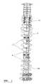
- FIG. 1shows a spinal column with spinal support elements of a spinal support kit according to the invention fastened to it by means of fixation devices.
- FIG. 2Aillustrates end views of spinal support elements which can be used in the kit of the invention.
- FIG. 2Billustrates side views of spinal support elements which can be used in the kit of the invention.
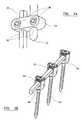
- FIG. 3Ais a perspective view of a fixation device for connecting a plurality of spinal support elements.
- FIG. 3Bis a perspective view of a plurality of fixation devices for connecting a spinal support element to bone.
- FIG. 3Cis a perspective view of a plurality of fixation devices for connecting a spinal support element to bone.
- FIG. 1shows a spinal column viewed posteriorly which comprises a plurality of vertebrae 2 .
- the posteriorly extending spinal process 4is visible.
- the present inventionprovides a kit which includes a plurality of spinal support elements 6 , each in the form of a rod, which can support the spinal column and, in particular, apply forces to the vertebrae to correct deformities.
- the kitcomprises two support elements 8 which are intended for use in the thoracic region which are formed from a shape memory alloy which consists of 50.8 at-% nickel and the balance (apart from impurities) titanium.
- the alloyhas been treated so that its A f temperature is about 20° C. This means that the alloy is able to exhibit superelastic properties, allowing it to be deformed in order to be fitted to the vertebrae. Once deformed (for example by as much as 8%), the element tends towards its configuration prior to deformation, applying forces to the vertebrae to which it is attached.
- the kitfurther includes support elements 10 which are formed from titanium which are intended for use in the lumbar region.
- the kitalso includes support elements 12 , also formed from titanium, which are intended for use in the cervical region.
- Support elements which are formed from titaniumhave the advantage that they can be cut to a desired length more easily that is the case with support elements which are formed from a nickel-titanium based alloy.
- the kitincludes fixation devices by which the spinal support elements can be fastened to the patient's vertebrae.
- the support elementsare fastened to the vertebrae by means of bone screws.
- Each bone screwpasses through an aperture in the base of a channel member which is dimensioned to receive a spinal support element between the side walls of the channel member.
- the internal side walls of the channel memberare threaded to engage the threads on the circumferential wall of a screw which can be located within the channel member to retain the support element therein.
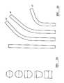
- FIG. 2 ashows cross-sections through spinal support elements which can be used in the kit of the invention.
- Suitable support elementscan have shapes when viewed in cross-section which are hexagonal, circular, half-round (with a flat face), trapezoidal and square.
- the support elementswill generally have the same cross-section from one end to the other end. However, it will often be appropriate for the cross-section to vary in at least some parts, especially at the ends of the rods.
- Reasons for changing the cross-sectioninclude ease of fixation in the fixation devices, and the desired degree to which torsional forces (when required) can be transmitted to fixation devices to which the support elements are attached.
- Suitable cross-sectional areas for the support elementsinclude about 12 mm 2 , 20 mm 2 , and 28 mm 2 .
- FIG. 2 bshows schematically the range of shapes of support elements which might be used in the kit of the invention.
- Examples of useful lengths of the rodsinclude 80 mm, 120 mm and 160 mm (or other lengths within and beyond this range).
- the support elementsmight be straight, or might define a Cobb angle of 18°, 42° or 50° (or other angles within and beyond this range).
- FIG. 3 ashows a fixation device by which two support elements 30 , 32 can be connected to one another side-by-side in a lap joint arrangement.
- one of the support elements 30has a square cross-section, at least at it end, and the other support element 32 has a round cross-section.
- the devicecomprises a housing 34 having two through bores 36 extending through it which are parallel. Each of the bores has a square cross-section so that the ends of the support elements are sliding fit therein.
- the housingalso has a pair of fixation bores formed in it extending generally perpendicular to the through bores 36 .
- the fixation boresare threaded internally so that each of them can receive a fixation screw 40 .
- the ends of the support elementsare inserted into respective ones of the through bores, and moved relative to the through bores until they are positioned appropriately having regard to the desired overall length of the implant.
- Each of the fixation screws 40is then tightened in the housing so that it acts on the inserted end of the respective support element.
- FIG. 3 bshows a fixation device of a commonly known type which can be used to fix a support element to bone tissue.
- the fixation devicecomprises a channel defined by side walls 46 and a base 48 .
- a support elementcan be fitted into the channel between the side walls.
- the channelhas a threaded shaft 50 extending from its base, which can be screwed into bone tissue.
- the configuration of the bone engaging threadis optimised as known.
- the internal surfaces 52 of the side wallsbear a thread, which can be engaged by a locking screw (not shown) to retain the support element in the channel, as known.
- FIG. 3 cshows another fixation device of a commonly known type which can be used to fix a support element to bone tissue.
- the fixation devicecomprises a channel defined by side walls 60 and a base 62 .
- a support elementcan be fitted into the channel between the side walls.
- the channelhas a hook 64 on its base, which can engage bone tissue on a patient's vertebra, as known.
- a support rod 66is located in the channel in the fixation device.
- spinal support kitsaccording to the invention are as follows:
- Cross-section Cross-section A f temperatureTensile strength Spinal levels Length (mm) shape dimensions (mm) Material (° C.) (MPa) L3-L1 100 6.0 Ti — 860 T12-T4 200 4.5 NiTi 32 551 T3-T1 80 3.5 Ti — 860 Fixation Elements
Landscapes
- Health & Medical Sciences (AREA)
- Orthopedic Medicine & Surgery (AREA)
- Life Sciences & Earth Sciences (AREA)
- Neurology (AREA)
- Surgery (AREA)
- Heart & Thoracic Surgery (AREA)
- Engineering & Computer Science (AREA)
- Biomedical Technology (AREA)
- Nuclear Medicine, Radiotherapy & Molecular Imaging (AREA)
- Medical Informatics (AREA)
- Molecular Biology (AREA)
- Animal Behavior & Ethology (AREA)
- General Health & Medical Sciences (AREA)
- Public Health (AREA)
- Veterinary Medicine (AREA)
- Prostheses (AREA)
Abstract
Description
- a. at least first and second support elements for fixation to vertebrae of a spinal column, extending generally along the spinal column between spaced apart vertebrae,
- b. a plurality of fixation devices for (i) fixing the support elements to one another in an end-to-end arrangement and (ii) fixing the support elements to the vertebrae,
in which at least the first support element is formed from a material which exhibits shape memory properties.
| Cross-section | Cross-section | Aftemperature | Tensile strength | |||
| Spinal levels | Length (mm) | shape | dimensions (mm) | Material | (° C.) | (MPa) |
| L5-L1 | 150 |  | 6.0 | NiTi | 15 | 551 |
| T12-T4 | 200 |  | 5.0 | 32 | 551 | |
| T3-C6 | 80 |  | 3.5 | Ti | — | 860 |
Fixation Elements
| Spinal levels | Fixation elements | ||
| L5-L1 | Pedicle screws | ||
| T12-T4 | Pedicle screws | ||
| T3-C6 | Hooks | ||
| Cross-section | Cross-section | Aftemperature | Tensile strength | |||
| Spinal levels | Length (mm) | shape | dimensions (mm) | Material | (° C.) | (MPa) |
| L3-L1 | 100 |  | 6.0 | Ti | — | 860 |
| T12-T4 | 200 |  | 4.5 | 32 | 551 | |
| T3-T1 | 80 |  | 3.5 | Ti | — | 860 |
Fixation Elements
| Spinal levels | Fixation elements | ||
| L3-L1 | Pedicle screws | ||
| T12-T4 | Hooks | ||
| T3-T1 | Pedicle screws | ||
Claims (20)
Applications Claiming Priority (3)
| Application Number | Priority Date | Filing Date | Title |
|---|---|---|---|
| GB0521582.7 | 2005-10-22 | ||
| GBGB0521582.7AGB0521582D0 (en) | 2005-10-22 | 2005-10-22 | An implant for supporting a spinal column |
| PCT/GB2006/003907WO2007045892A1 (en) | 2005-10-22 | 2006-10-20 | An implant kit for supporting a spinal column |
Publications (2)
| Publication Number | Publication Date |
|---|---|
| US20090222042A1 US20090222042A1 (en) | 2009-09-03 |
| US8414614B2true US8414614B2 (en) | 2013-04-09 |
Family
ID=35458544
Family Applications (1)
| Application Number | Title | Priority Date | Filing Date |
|---|---|---|---|
| US12/090,806Active2028-10-31US8414614B2 (en) | 2005-10-22 | 2006-10-20 | Implant kit for supporting a spinal column |
Country Status (4)
| Country | Link |
|---|---|
| US (1) | US8414614B2 (en) |
| EP (1) | EP1937167A1 (en) |
| GB (1) | GB0521582D0 (en) |
| WO (1) | WO2007045892A1 (en) |
Cited By (16)
| Publication number | Priority date | Publication date | Assignee | Title |
|---|---|---|---|---|
| US20130103088A1 (en)* | 2011-09-16 | 2013-04-25 | Lanx, Inc. | Segmental Spinous Process Anchor System and Methods of Use |
| US8828058B2 (en) | 2008-11-11 | 2014-09-09 | Kspine, Inc. | Growth directed vertebral fixation system with distractible connector(s) and apical control |
| US8920472B2 (en) | 2011-11-16 | 2014-12-30 | Kspine, Inc. | Spinal correction and secondary stabilization |
| US9011491B2 (en) | 2004-08-03 | 2015-04-21 | K Spine, Inc. | Facet device and method |
| US9168071B2 (en) | 2009-09-15 | 2015-10-27 | K2M, Inc. | Growth modulation system |
| US9173681B2 (en) | 2009-03-26 | 2015-11-03 | K2M, Inc. | Alignment system with longitudinal support features |
| US9333009B2 (en) | 2011-06-03 | 2016-05-10 | K2M, Inc. | Spinal correction system actuators |
| US9468468B2 (en) | 2011-11-16 | 2016-10-18 | K2M, Inc. | Transverse connector for spinal stabilization system |
| US9468471B2 (en) | 2013-09-17 | 2016-10-18 | K2M, Inc. | Transverse coupler adjuster spinal correction systems and methods |
| US9468469B2 (en) | 2011-11-16 | 2016-10-18 | K2M, Inc. | Transverse coupler adjuster spinal correction systems and methods |
| US20180064469A1 (en)* | 2015-04-24 | 2018-03-08 | K2M, Inc. | Tethering screw system |
| US10342581B2 (en) | 2011-11-16 | 2019-07-09 | K2M, Inc. | System and method for spinal correction |
| US10702311B2 (en) | 2011-11-16 | 2020-07-07 | K2M, Inc. | Spinal correction and secondary stabilization |
| US20210290272A1 (en)* | 2015-12-23 | 2021-09-23 | Xiangyang Ma | Customized posterior atlantoaxial reduction fixatorwith screws and rods |
| US11291478B2 (en) | 2016-02-12 | 2022-04-05 | Nuvasive, Inc. | Post-operatively adjustable spinal fixation devices |
| US20220387082A1 (en)* | 2020-10-28 | 2022-12-08 | Globus Medical, Inc. | Articulating connectors, systems, and methods thereof |
Families Citing this family (34)
| Publication number | Priority date | Publication date | Assignee | Title |
|---|---|---|---|---|
| WO2006016371A2 (en)* | 2004-08-13 | 2006-02-16 | Mazor Surgical Technologies Ltd | Minimally invasive spinal fusion |
| GB0521582D0 (en) | 2005-10-22 | 2005-11-30 | Depuy Int Ltd | An implant for supporting a spinal column |
| US8100946B2 (en) | 2005-11-21 | 2012-01-24 | Synthes Usa, Llc | Polyaxial bone anchors with increased angulation |
| GB0600662D0 (en) | 2006-01-13 | 2006-02-22 | Depuy Int Ltd | Spinal support rod kit |
| US8348952B2 (en) | 2006-01-26 | 2013-01-08 | Depuy International Ltd. | System and method for cooling a spinal correction device comprising a shape memory material for corrective spinal surgery |
| US8398637B2 (en)* | 2006-11-06 | 2013-03-19 | Douglas Eric Parsell | Device and method for less invasive surgical stabilization of pelvic fractures |
| US20080269805A1 (en) | 2007-04-25 | 2008-10-30 | Warsaw Orthopedic, Inc. | Methods for correcting spinal deformities |
| US9439681B2 (en) | 2007-07-20 | 2016-09-13 | DePuy Synthes Products, Inc. | Polyaxial bone fixation element |
| DE502007005279D1 (en)* | 2007-09-17 | 2010-11-18 | Aleksandr Andreewitsch Laka | Device for the correction of kyphotic deformations of the spine |
| US20090088803A1 (en)* | 2007-10-01 | 2009-04-02 | Warsaw Orthopedic, Inc. | Flexible members for correcting spinal deformities |
| GB0720762D0 (en) | 2007-10-24 | 2007-12-05 | Depuy Spine Sorl | Assembly for orthopaedic surgery |
| US20100063548A1 (en)* | 2008-07-07 | 2010-03-11 | Depuy International Ltd | Spinal Correction Method Using Shape Memory Spinal Rod |
| WO2010017471A1 (en)* | 2008-08-07 | 2010-02-11 | The Children's Mercy Hospital | Sliding rod system for correcting spinal deformities |
| US8979905B2 (en)* | 2008-09-10 | 2015-03-17 | Life Spine, Inc. | Spinal rod |
| JP5815407B2 (en) | 2008-09-12 | 2015-11-17 | ジンテス ゲゼルシャフト ミット ベシュレンクテル ハフツング | Spinal stabilization and guided fixation system |
| KR20110081208A (en) | 2008-09-29 | 2011-07-13 | 신세스 게엠바하 | Multi-Axis Bottom-Loading Screw and Rod Assemblies |
| CA2742399A1 (en) | 2008-11-03 | 2010-06-03 | Dustin M. Harvey | Uni-planar bone fixation assembly |
| GB2465156B (en)* | 2008-11-05 | 2012-09-26 | Dalmatic Lystrup As | Bone fixation system |
| KR20120013312A (en) | 2009-04-15 | 2012-02-14 | 신세스 게엠바하 | Orthodontic Connectors for Spinal Structures |
| CA2764841A1 (en) | 2009-06-17 | 2010-12-23 | Synthes Usa, Llc | Revision connector for spinal constructs |
| US9138264B2 (en)* | 2009-11-02 | 2015-09-22 | Life Spine, Inc. | Laminoplasty rod system |
| DK2608728T3 (en) | 2010-08-26 | 2018-01-22 | Spinesave Ag | Vertebral column implant kit for dynamic stabilization of the vertebral column |
| US8882806B2 (en) | 2011-04-25 | 2014-11-11 | Said ELSHIHABI | Spine stabilization system with self-cutting rod |
| US10327818B2 (en) | 2012-06-18 | 2019-06-25 | Bruce Francis Hodgson | Method and apparatus for the treatment of scoliosis |
| CA2903160A1 (en)* | 2012-06-18 | 2014-12-27 | Bruce Francis HODGSON | Method and apparatus for the treatment of scoliosis |
| US9237907B2 (en) | 2013-03-05 | 2016-01-19 | Warsaw Orthopedic, Inc. | Spinal correction system and method |
| US10321939B2 (en) | 2016-05-18 | 2019-06-18 | Medos International Sarl | Implant connectors and related methods |
| US10517647B2 (en) | 2016-05-18 | 2019-12-31 | Medos International Sarl | Implant connectors and related methods |
| CN105919662A (en)* | 2016-07-08 | 2016-09-07 | 湖南百佳生物工程有限公司 | Spine fixing system |
| US10492835B2 (en) | 2016-12-19 | 2019-12-03 | Medos International Sàrl | Offset rods, offset rod connectors, and related methods |
| US10238432B2 (en) | 2017-02-10 | 2019-03-26 | Medos International Sàrl | Tandem rod connectors and related methods |
| US10561454B2 (en) | 2017-03-28 | 2020-02-18 | Medos International Sarl | Articulating implant connectors and related methods |
| US10966761B2 (en)* | 2017-03-28 | 2021-04-06 | Medos International Sarl | Articulating implant connectors and related methods |
| US11076890B2 (en) | 2017-12-01 | 2021-08-03 | Medos International Sàrl | Rod-to-rod connectors having robust rod closure mechanisms and related methods |
Citations (346)
| Publication number | Priority date | Publication date | Assignee | Title |
|---|---|---|---|---|
| US2669896A (en) | 1951-01-19 | 1954-02-23 | Robert S Clough | Retractable jaw wrench having parallel resilient jaws |
| US2952285A (en) | 1958-12-09 | 1960-09-13 | Gramiger A G Geb | Screwdrivers |
| US3604487A (en) | 1969-03-10 | 1971-09-14 | Richard S Gilbert | Orthopedic screw driving means |
| US3786806A (en) | 1972-11-22 | 1974-01-22 | A Johnson | Thermoconstrictive surgical appliance |
| US3915160A (en) | 1972-03-03 | 1975-10-28 | Lode Insrumenen B V | Apparatus for exerting forces and/or torques on the human spine |
| US4289123A (en) | 1980-03-31 | 1981-09-15 | Dunn Harold K | Orthopedic appliance |
| US4363250A (en) | 1980-04-04 | 1982-12-14 | Asakichi Suga | Device for driving screw, pin, rivet or the like |
| US4592933A (en) | 1984-06-29 | 1986-06-03 | International Business Machines Corporation | High efficiency homogeneous chemical vapor deposition |
| US4611582A (en) | 1983-12-27 | 1986-09-16 | Wisconsin Alumni Research Foundation | Vertebral clamp |
| US4697582A (en) | 1983-10-28 | 1987-10-06 | Peze William | Appliance for correcting rachidial deformities |
| US4733657A (en) | 1984-04-16 | 1988-03-29 | Patrick Kluger | Apparatus for aligning a spinal column having damaged vertebrae |
| US4743260A (en) | 1985-06-10 | 1988-05-10 | Burton Charles V | Method for a flexible stabilization system for a vertebral column |
| US4887596A (en) | 1988-03-02 | 1989-12-19 | Synthes (U.S.A.) | Open backed pedicle screw |
| US4957495A (en) | 1987-04-01 | 1990-09-18 | Patrick Kluger | Device for setting the spinal column |
| US4987892A (en) | 1989-04-04 | 1991-01-29 | Krag Martin H | Spinal fixation device |
| US5005562A (en) | 1988-06-24 | 1991-04-09 | Societe De Fabrication De Material Orthopedique | Implant for spinal osteosynthesis device, in particular in traumatology |
| US5042982A (en) | 1987-07-08 | 1991-08-27 | Harms Juergen | Positioning device |
| US5067955A (en) | 1989-04-13 | 1991-11-26 | Societe De Fabrication De Material Orthopedique | Vertebral implant for osteosynthesis device |
| US5092866A (en) | 1989-02-03 | 1992-03-03 | Breard Francis H | Flexible inter-vertebral stabilizer as well as process and apparatus for determining or verifying its tension before installation on the spinal column |
| US5102412A (en) | 1990-06-19 | 1992-04-07 | Chaim Rogozinski | System for instrumentation of the spine in the treatment of spinal deformities |
| US5120171A (en) | 1990-11-27 | 1992-06-09 | Stuart Surgical | Bone screw with improved threads |
| US5129388A (en) | 1989-02-09 | 1992-07-14 | Vignaud Jean Louis | Device for supporting the spinal column |
| US5129900A (en) | 1990-07-24 | 1992-07-14 | Acromed Corporation | Spinal column retaining method and apparatus |
| US5133716A (en) | 1990-11-07 | 1992-07-28 | Codespi Corporation | Device for correction of spinal deformities |
| US5176680A (en) | 1990-02-08 | 1993-01-05 | Vignaud Jean Louis | Device for the adjustable fixing of spinal osteosynthesis rods |
| US5176678A (en) | 1991-03-14 | 1993-01-05 | Tsou Paul M | Orthopaedic device with angularly adjustable anchor attachments to the vertebrae |
| US5190543A (en) | 1990-11-26 | 1993-03-02 | Synthes (U.S.A.) | Anchoring device |
| US5207678A (en) | 1989-07-20 | 1993-05-04 | Prufer | Pedicle screw and receiver member therefore |
| US5219349A (en) | 1991-02-15 | 1993-06-15 | Howmedica, Inc. | Spinal fixator reduction frame |
| US5226766A (en) | 1990-11-27 | 1993-07-13 | Stuart Surgical | Bone screw with improved threads |
| US5263939A (en) | 1992-10-09 | 1993-11-23 | Surgin Surgical Instrumentation, Inc. | Retainer for laparoscopic cannula |
| US5282801A (en) | 1993-02-17 | 1994-02-01 | Danek Medical, Inc. | Top tightening clamp assembly for a spinal fixation system |
| US5290289A (en) | 1990-05-22 | 1994-03-01 | Sanders Albert E | Nitinol spinal instrumentation and method for surgically treating scoliosis |
| FR2624720B1 (en) | 1987-12-21 | 1994-04-15 | Fabrication Materiel Orthopediqu | IMPLANT FOR OSTEOSYNTHESIS DEVICE, ESPECIALLY OF THE RACHIS |
| US5330473A (en) | 1993-03-04 | 1994-07-19 | Advanced Spine Fixation Systems, Inc. | Branch connector for spinal fixation systems |
| DE4107480C2 (en) | 1991-03-08 | 1994-09-22 | Heinrich Ulrich | Pedicle screw for implants to correct and stabilize the spine |
| US5360431A (en) | 1990-04-26 | 1994-11-01 | Cross Medical Products | Transpedicular screw system and method of use |
| US5385565A (en) | 1992-09-21 | 1995-01-31 | Danek Medical, Inc. | Tool and method for derotating scoliotic spine |
| US5387213A (en) | 1991-02-05 | 1995-02-07 | Safir S.A.R.L. | Osseous surgical implant particularly for an intervertebral stabilizer |
| US5387212A (en) | 1993-01-26 | 1995-02-07 | Yuan; Hansen A. | Vertebral locking and retrieving system with central locking rod |
| US5391168A (en) | 1992-04-01 | 1995-02-21 | Acromed B.V. | Device for correcting the shape of the human spinal column and/or for fixing the human spinal column |
| DE4330837A1 (en) | 1993-09-11 | 1995-03-16 | Michael Hahn | Pedicle screw and internal fixator |
| US5413576A (en) | 1993-02-10 | 1995-05-09 | Rivard; Charles-Hilaire | Apparatus for treating spinal disorder |
| US5415661A (en) | 1993-03-24 | 1995-05-16 | University Of Miami | Implantable spinal assist device |
| US5437673A (en) | 1993-02-04 | 1995-08-01 | Cryomedical Sciences, Inc. | Closed circulation tissue warming apparatus and method of using the same in prostate surgery |
| US5437669A (en) | 1993-08-12 | 1995-08-01 | Amei Technologies Inc. | Spinal fixation systems with bifurcated connectors |
| US5445140A (en) | 1993-06-07 | 1995-08-29 | United States Surgical Corporation | Endoscopic surgical device |
| US5466238A (en) | 1993-08-27 | 1995-11-14 | Lin; Chih-I | Vertebral locking and retrieving system having a fixation crossbar |
| US5468241A (en) | 1988-02-18 | 1995-11-21 | Howmedica Gmbh | Support device for the human vertebral column |
| US5487744A (en) | 1993-04-08 | 1996-01-30 | Advanced Spine Fixation Systems, Inc. | Closed connector for spinal fixation systems |
| US5487742A (en) | 1990-03-08 | 1996-01-30 | Sofamore Danek Group | Transverse fixation device for a spinal osteosynthesis system |
| US5499983A (en) | 1994-02-23 | 1996-03-19 | Smith & Nephew Richards, Inc. | Variable angle spinal screw |
| US5501684A (en) | 1992-06-25 | 1996-03-26 | Synthes (U.S.A.) | Osteosynthetic fixation device |
| US5520689A (en) | 1992-06-04 | 1996-05-28 | Synthes (U.S.A.) | Osteosynthetic fastening device |
| US5536127A (en) | 1994-10-13 | 1996-07-16 | Pennig; Dietmar | Headed screw construction for use in fixing the position of an intramedullary nail |
| US5536268A (en) | 1992-12-23 | 1996-07-16 | Plus Endoprothetik Ag | System for osteosynthesis at the vertebral column, connecting element for such a system and tool for its placement and removal |
| US5540688A (en) | 1991-05-30 | 1996-07-30 | Societe "Psi" | Intervertebral stabilization device incorporating dampers |
| US5540689A (en) | 1990-05-22 | 1996-07-30 | Sanders; Albert E. | Apparatus for securing a rod adjacent to a bone |
| US5545165A (en) | 1992-10-09 | 1996-08-13 | Biedermann Motech Gmbh | Anchoring member |
| US5549608A (en) | 1995-07-13 | 1996-08-27 | Fastenetix, L.L.C. | Advanced polyaxial locking screw and coupling element device for use with rod fixation apparatus |
| US5549552A (en) | 1995-03-02 | 1996-08-27 | Scimed Life Systems, Inc. | Balloon dilation catheter with improved pushability, trackability and crossability |
| US5586983A (en) | 1990-05-22 | 1996-12-24 | Sanders; Albert E. | Bone clamp of shape memory material |
| US5591166A (en) | 1995-03-27 | 1997-01-07 | Smith & Nephew Richards, Inc. | Multi angle bone bolt |
| US5593408A (en) | 1994-11-30 | 1997-01-14 | Sofamor S.N.C | Vertebral instrumentation rod |
| US5593407A (en) | 1991-10-26 | 1997-01-14 | Reis; Nicolas D. | Internal ilio-lumbar fixator |
| US5597378A (en) | 1983-10-14 | 1997-01-28 | Raychem Corporation | Medical devices incorporating SIM alloy elements |
| US5601552A (en) | 1994-03-18 | 1997-02-11 | Sofamor, S.N.C. | Fixing device for a rigid transverse connection device between rods of a spinal osteosynthesis system |
| US5626581A (en) | 1995-11-27 | 1997-05-06 | Volunteers For Medical Engineering | Implantable bone lengthening apparatus |
| US5630816A (en) | 1995-05-01 | 1997-05-20 | Kambin; Parviz | Double barrel spinal fixation system and method |
| US5645520A (en) | 1994-10-12 | 1997-07-08 | Computer Motion, Inc. | Shape memory alloy actuated rod for endoscopic instruments |
| US5649931A (en) | 1996-01-16 | 1997-07-22 | Zimmer, Inc. | Orthopaedic apparatus for driving and/or removing a bone screw |
| US5658286A (en) | 1996-02-05 | 1997-08-19 | Sava; Garard A. | Fabrication of implantable bone fixation elements |
| US5667513A (en) | 1995-06-07 | 1997-09-16 | Smith & Nephew Dyonics Inc. | Soft tissue anchor delivery apparatus |
| US5672176A (en) | 1995-03-15 | 1997-09-30 | Biedermann; Lutz | Anchoring member |
| US5672175A (en) | 1993-08-27 | 1997-09-30 | Martin; Jean Raymond | Dynamic implanted spinal orthosis and operative procedure for fitting |
| US5702452A (en) | 1995-01-23 | 1997-12-30 | Sofamor S.N.C. | Spinal osteosynthesis device with median hook and vertebral anchoring support |
| US5738685A (en) | 1993-05-18 | 1998-04-14 | Schafer Micomed Gmbh | Osteosynthesis device |
| US5766004A (en) | 1993-03-05 | 1998-06-16 | Sofamor Danek Holdings, Inc. | Temperature sensitive medical dental apparatus |
| US5797911A (en) | 1996-09-24 | 1998-08-25 | Sdgi Holdings, Inc. | Multi-axial bone screw assembly |
| US5830179A (en) | 1996-04-09 | 1998-11-03 | Endocare, Inc. | Urological stent therapy system and method |
| US5833707A (en) | 1995-07-05 | 1998-11-10 | Advanced Cardiovascular Systems, Inc. | Removable stent and method of deployment |
| US5879350A (en) | 1996-09-24 | 1999-03-09 | Sdgi Holdings, Inc. | Multi-axial bone screw assembly |
| US5885285A (en) | 1995-08-14 | 1999-03-23 | Simonson; Peter Melott | Spinal implant connection assembly |
| FR2759894B1 (en) | 1997-02-24 | 1999-03-26 | Khalil Kharrat | OFFSET CHANNEL IMPLANT FOR INTERVERTEBRAL OSTEOSYNTHESIS IN PARTICULAR WITH CATCHING HOOK |
| USRE36221E (en) | 1989-02-03 | 1999-06-01 | Breard; Francis Henri | Flexible inter-vertebral stabilizer as well as process and apparatus for determining or verifying its tension before installation on the spinal column |
| US5910142A (en) | 1998-10-19 | 1999-06-08 | Bones Consulting, Llc | Polyaxial pedicle screw having a rod clamping split ferrule coupling element |
| US5910141A (en) | 1997-02-12 | 1999-06-08 | Sdgi Holdings, Inc. | Rod introduction apparatus |
| US5919158A (en) | 1997-02-13 | 1999-07-06 | Emory University | Method and apparatus for preventing and clearing condensation on the lens during a fluid-gas exchange portion of a pars plana vitrectomy |
| US5947965A (en) | 1992-12-31 | 1999-09-07 | Bryan; Donald W. | Spinal fixation apparatus and method |
| US5947966A (en) | 1995-06-06 | 1999-09-07 | Sdgi Holdings, Inc. | Device for linking adjacent rods in spinal instrumentation |
| US5951555A (en) | 1996-03-27 | 1999-09-14 | Rehak; Lubos | Device for the correction of spinal deformities |
| US5961515A (en) | 1995-03-01 | 1999-10-05 | Smith & Nephew, Inc. | External skeletal fixation system |
| US5964760A (en) | 1996-10-18 | 1999-10-12 | Spinal Innovations | Spinal implant fixation assembly |
| US5964770A (en) | 1997-09-30 | 1999-10-12 | Litana Ltd. | High strength medical devices of shape memory alloy |
| US5989254A (en) | 1997-05-20 | 1999-11-23 | Katz; Akiva Raphael | Pedicle screw assembly |
| US5989250A (en) | 1996-10-24 | 1999-11-23 | Spinal Concepts, Inc. | Method and apparatus for spinal fixation |
| US5997580A (en) | 1997-03-27 | 1999-12-07 | Johnson & Johnson Professional, Inc. | Cement restrictor including shape memory material |
| US6050997A (en) | 1999-01-25 | 2000-04-18 | Mullane; Thomas S. | Spinal fixation system |
| US6063090A (en) | 1996-12-12 | 2000-05-16 | Synthes (U.S.A.) | Device for connecting a longitudinal support to a pedicle screw |
| US6071250A (en) | 1997-05-16 | 2000-06-06 | Amira Medical | Methods and apparatus for expressing body fluid from an incision |
| US6074391A (en) | 1997-06-16 | 2000-06-13 | Howmedica Gmbh | Receiving part for a retaining component of a vertebral column implant |
| US6077262A (en) | 1993-06-04 | 2000-06-20 | Synthes (U.S.A.) | Posterior spinal implant |
| US6090113A (en) | 1996-12-27 | 2000-07-18 | Stryker France S.A. | Adjustable osteosynthesis system of the rachis |
| US6090110A (en) | 1992-03-02 | 2000-07-18 | Howmedica Gmbh | Apparatus for bracing vertebrae |
| US6102912A (en) | 1997-05-29 | 2000-08-15 | Sofamor S.N.C. | Vertebral rod of constant section for spinal osteosynthesis instrumentations |
| US6106527A (en) | 1998-04-29 | 2000-08-22 | National Science Council | Vertebral fixing device |
| US6110172A (en) | 1998-07-31 | 2000-08-29 | Jackson; Roger P. | Closure system for open ended osteosynthesis apparatus |
| US6127597A (en) | 1997-03-07 | 2000-10-03 | Discotech N.V. | Systems for percutaneous bone and spinal stabilization, fixation and repair |
| US6139549A (en) | 1996-04-09 | 2000-10-31 | Waldemar Link (Gmbh & Co.) | Spinal fixing device |
| US6139548A (en) | 1995-10-30 | 2000-10-31 | Spinal Concepts, Inc. | Sliding shaft variable length cross-link device for use with dual rod apparatus |
| US6146383A (en) | 1998-02-02 | 2000-11-14 | Sulzer Orthopadie Ag | Pivotal securing system at a bone screw |
| US6183472B1 (en) | 1998-04-09 | 2001-02-06 | Howmedica Gmbh | Pedicle screw and an assembly aid therefor |
| US6200317B1 (en) | 1996-12-23 | 2001-03-13 | Universiteit Twente And Technologiestichting Stw | Device for moving two objects relative to each other |
| US6204060B1 (en) | 1995-07-24 | 2001-03-20 | Transgene S.A. | Viral vectors and line for gene therapy |
| FR2786088B1 (en) | 1998-11-24 | 2001-04-06 | Dimso Sa | SPINAL OSTEOSYNTHESIS DEVICE WITH TIGHTENING RING |
| US6214730B1 (en) | 1996-11-08 | 2001-04-10 | International Business Machines Corporation | Fluorine barrier layer between conductor and insulator for degradation prevention |
| US6235028B1 (en) | 2000-02-14 | 2001-05-22 | Sdgi Holdings, Inc. | Surgical guide rod |
| US6238491B1 (en) | 1999-05-05 | 2001-05-29 | Davitech, Inc. | Niobium-titanium-zirconium-molybdenum (nbtizrmo) alloys for dental and other medical device applications |
| US6241730B1 (en) | 1997-11-26 | 2001-06-05 | Scient'x (Societe A Responsabilite Limitee) | Intervertebral link device capable of axial and angular displacement |
| US6254602B1 (en) | 1999-05-28 | 2001-07-03 | Sdgi Holdings, Inc. | Advanced coupling device using shape-memory technology |
| US6261288B1 (en) | 2000-02-08 | 2001-07-17 | Roger P. Jackson | Implant stabilization and locking system |
| US6267764B1 (en) | 1996-11-15 | 2001-07-31 | Stryker France S.A. | Osteosynthesis system with elastic deformation for spinal column |
| DE10005385A1 (en) | 2000-02-07 | 2001-08-09 | Ulrich Gmbh & Co Kg | Pedicle screw |
| DE10005386A1 (en) | 2000-02-07 | 2001-08-09 | Ulrich Gmbh & Co Kg | Pedicle screw for spinal implants takes round bar whose longitudinally rotating shoe notchably accepts notch-legged clip for bar. |
| US6273914B1 (en) | 1995-09-28 | 2001-08-14 | Sparta, Inc. | Spinal implant |
| US6280442B1 (en) | 1999-09-01 | 2001-08-28 | Sdgi Holdings, Inc. | Multi-axial bone screw assembly |
| US6280443B1 (en) | 1999-01-30 | 2001-08-28 | Ja-Kyo Gu | Spinal fixation system |
| US6293949B1 (en) | 2000-03-01 | 2001-09-25 | Sdgi Holdings, Inc. | Superelastic spinal stabilization system and method |
| FR2806615A1 (en) | 2000-03-21 | 2001-09-28 | Cremascolli Ortho S A | Vertebral fracture reducing apparatus has fixings shaped to receive cylindrical components holding linking rods |
| US6299216B1 (en) | 1996-07-03 | 2001-10-09 | Codelast Limited | Joints |
| US6302888B1 (en) | 1999-03-19 | 2001-10-16 | Interpore Cross International | Locking dovetail and self-limiting set screw assembly for a spinal stabilization member |
| US6309389B1 (en) | 1997-02-26 | 2001-10-30 | Stryker France, S.A. | Ring for an angulation osteosynthesis device and osteosynthesis device incorporating same |
| US6309391B1 (en) | 2000-03-15 | 2001-10-30 | Sdgi Holding, Inc. | Multidirectional pivoting bone screw and fixation system |
| US6325805B1 (en) | 1999-04-23 | 2001-12-04 | Sdgi Holdings, Inc. | Shape memory alloy staple |
| US6328741B1 (en) | 1996-10-18 | 2001-12-11 | Spinal Innovations, Llc | Transverse connector |
| US20020032442A1 (en) | 2000-06-09 | 2002-03-14 | Moti Altarac | Adjustable transverse connector for use with a spinal implant system |
| US20020035366A1 (en) | 2000-09-18 | 2002-03-21 | Reto Walder | Pedicle screw for intervertebral support elements |
| US6361637B2 (en) | 1995-12-14 | 2002-03-26 | Gore Enterprise Holdings, Inc. | Method of making a kink resistant stent-graft |
| US6368321B1 (en) | 2000-12-04 | 2002-04-09 | Roger P. Jackson | Lockable swivel head bone screw |
| US6379357B1 (en) | 1994-10-25 | 2002-04-30 | Sdgi Holdings, Inc. | Modular spinal system |
| US6389710B1 (en) | 1998-09-24 | 2002-05-21 | Yin Yen Co., Ltd. | Structure of an infrared hair drier |
| US6423065B2 (en) | 2000-02-25 | 2002-07-23 | Bret A. Ferree | Cross-coupled vertebral stabilizers including cam-operated cable connectors |
| US6440133B1 (en) | 2001-07-03 | 2002-08-27 | Sdgi Holdings, Inc. | Rod reducer instruments and methods |
| US6440137B1 (en) | 2000-04-18 | 2002-08-27 | Andres A. Horvath | Medical fastener cap system |
| US6443953B1 (en) | 2000-02-08 | 2002-09-03 | Cross Medical Products, Inc. | Self-aligning cap nut for use with a spinal rod anchor |
| US6447478B1 (en) | 1998-05-15 | 2002-09-10 | Ronald S. Maynard | Thin-film shape memory alloy actuators and processing methods |
| US20020133155A1 (en) | 2000-02-25 | 2002-09-19 | Ferree Bret A. | Cross-coupled vertebral stabilizers incorporating spinal motion restriction |
| US20020138077A1 (en) | 2001-03-26 | 2002-09-26 | Ferree Bret A. | Spinal alignment apparatus and methods |
| US20020143341A1 (en) | 2001-03-27 | 2002-10-03 | Lutz Biedermann | Anchoring element |
| US20020143327A1 (en) | 2001-03-27 | 2002-10-03 | Endius Incorporated | Transverse connector for use in spinal corrective surgery |
| US6471716B1 (en) | 2000-07-11 | 2002-10-29 | Joseph P. Pecukonis | Low level light therapy method and apparatus with improved wavelength, temperature and voltage control |
| US6478798B1 (en) | 2001-05-17 | 2002-11-12 | Robert S. Howland | Spinal fixation apparatus and methods for use |
| US20020169449A1 (en) | 2001-04-19 | 2002-11-14 | Kuslich Stephen D. | Stacked intermedular rods for spinal fixation |
| US6485492B1 (en) | 1998-08-08 | 2002-11-26 | Bernd Schafer | Osteosynthesis device |
| US6485491B1 (en) | 2000-09-15 | 2002-11-26 | Sdgi Holdings, Inc. | Posterior fixation system |
| US20030023240A1 (en) | 1997-01-22 | 2003-01-30 | Synthes (Usa) | Device for connecting a longitudinal bar to a pedicle screw |
| US6517533B1 (en) | 1997-07-29 | 2003-02-11 | M. J. Swaminathan | Balloon catheter for controlling tissue remodeling and/or tissue proliferation |
| US6520962B1 (en) | 2000-10-23 | 2003-02-18 | Sdgi Holdings, Inc. | Taper-locked adjustable connector |
| EP1295566A1 (en) | 1999-06-30 | 2003-03-26 | Surgival Co., S.A. | Polyaxial vertebral fixing system |
| US6540749B2 (en) | 2001-02-17 | 2003-04-01 | Bernd Schäfer | Bone screw |
| US6540748B2 (en) | 1999-09-27 | 2003-04-01 | Blackstone Medical, Inc. | Surgical screw system and method of use |
| US20030073995A1 (en) | 2001-10-15 | 2003-04-17 | Reed Gary Jack | Orthopedic stabilization device and method |
| US6551320B2 (en) | 2000-11-08 | 2003-04-22 | The Cleveland Clinic Foundation | Method and apparatus for correcting spinal deformity |
| US6554834B1 (en) | 1999-10-07 | 2003-04-29 | Stryker Spine | Slotted head pedicle screw assembly |
| US20030083657A1 (en) | 2001-10-30 | 2003-05-01 | Drewry Troy D. | Flexible spinal stabilization system and method |
| US20030088248A1 (en) | 2001-11-07 | 2003-05-08 | Reed Gary Jack | Orthopedic stabilization device and method |
| US6565567B1 (en) | 1996-12-20 | 2003-05-20 | Thomas T. Haider | Pedicle screw for osteosynthesis |
| US20030100896A1 (en) | 2001-11-27 | 2003-05-29 | Lutz Biedermann | Element with a shank and a holding element connected to it for connecting to a rod |
| US20030105460A1 (en) | 2000-03-15 | 2003-06-05 | Dennis Crandall | Multidirectional pivoting bone screw and fixation system |
| US20030109880A1 (en) | 2001-08-01 | 2003-06-12 | Showa Ika Kohgyo Co., Ltd. | Bone connector |
| US20030114853A1 (en) | 2001-10-12 | 2003-06-19 | Ian Burgess | Polyaxial cross connector |
| FR2813782B1 (en) | 2000-09-13 | 2003-07-18 | Eurosurgical | ANCILLARY FOR THE CORRECTION OF A RACHIDIAN SEGMENT AND THE PLACEMENT OF A RACHIDIAN OSTEOSYNTHESIS DEVICE CONNECTING EACH VERTEBRA OF THE RACHIDIAN SEGMENT TO BE CORRECTED |
| US6597279B1 (en) | 1998-03-06 | 2003-07-22 | Sony Corporation | Portable information terminal and method of setting the same |
| US6616669B2 (en) | 1999-04-23 | 2003-09-09 | Sdgi Holdings, Inc. | Method for the correction of spinal deformities through vertebral body tethering without fusion |
| US20030171749A1 (en) | 2000-07-25 | 2003-09-11 | Regis Le Couedic | Semirigid linking piece for stabilizing the spine |
| US20030176861A1 (en) | 2002-03-15 | 2003-09-18 | Reed Gary J. | Orthopedic stabilization device and method |
| US6623485B2 (en) | 2001-10-17 | 2003-09-23 | Hammill Manufacturing Company | Split ring bone screw for a spinal fixation system |
| US20030191470A1 (en) | 2002-04-05 | 2003-10-09 | Stephen Ritland | Dynamic fixation device and method of use |
| US6648888B1 (en) | 2002-09-06 | 2003-11-18 | Endius Incorporated | Surgical instrument for moving a vertebra |
| US6652526B1 (en) | 2001-10-05 | 2003-11-25 | Ruben P. Arafiles | Spinal stabilization rod fastener |
| US20030220643A1 (en) | 2002-05-24 | 2003-11-27 | Ferree Bret A. | Devices to prevent spinal extension |
| US20030220642A1 (en) | 2002-05-21 | 2003-11-27 | Stefan Freudiger | Elastic stabilization system for vertebral columns |
| US6660006B2 (en) | 2002-04-17 | 2003-12-09 | Stryker Spine | Rod persuader |
| US20040002708A1 (en) | 2002-05-08 | 2004-01-01 | Stephen Ritland | Dynamic fixation device and method of use |
| US6689137B2 (en) | 2001-10-15 | 2004-02-10 | Gary Jack Reed | Orthopedic fastener and method |
| US6695843B2 (en) | 2000-12-22 | 2004-02-24 | Biedermann Motech Gmbh | Fixing element |
| US20040049190A1 (en) | 2002-08-09 | 2004-03-11 | Biedermann Motech Gmbh | Dynamic stabilization device for bones, in particular for vertebrae |
| US20040049189A1 (en) | 2000-07-25 | 2004-03-11 | Regis Le Couedic | Flexible linking piece for stabilising the spine |
| US6716214B1 (en) | 2003-06-18 | 2004-04-06 | Roger P. Jackson | Polyaxial bone screw with spline capture connection |
| US20040073215A1 (en) | 2002-10-14 | 2004-04-15 | Scient ' X | Dynamic intervertebral connection device with controlled multidirectional deflection |
| US6730087B1 (en) | 1998-07-02 | 2004-05-04 | Michael Butsch | Bone distraction device |
| US6733502B2 (en) | 2002-05-15 | 2004-05-11 | Cross Medical Products, Inc. | Variable locking spinal screw having a knurled collar |
| US6733531B1 (en) | 2000-10-20 | 2004-05-11 | Sdgi Holdings, Inc. | Anchoring devices and implants for intervertebral disc augmentation |
| WO2004041100A1 (en) | 2002-10-30 | 2004-05-21 | Spinal Concepts, Inc. | Spinal stabilization system insertion and methods |
| US6743231B1 (en) | 2000-10-02 | 2004-06-01 | Sulzer Spine-Tech Inc. | Temporary spinal fixation apparatuses and methods |
| US20040106921A1 (en) | 2002-08-25 | 2004-06-03 | Cheung Kenneth Mc | Device for correcting spinal deformities |
| US6749613B1 (en) | 1999-02-18 | 2004-06-15 | Stryker Spine | Distraction/contraction device for spinal osteosynthesis system |
| US6755829B1 (en) | 2000-09-22 | 2004-06-29 | Depuy Acromed, Inc. | Lock cap anchor assembly for orthopaedic fixation |
| WO2004019755A3 (en) | 2002-08-28 | 2004-07-08 | Richard B Ashman | Variable angle spinal implant connection assembly |
| US20040158258A1 (en) | 2003-02-12 | 2004-08-12 | Bonati Alfred O. | Method for removing orthopaedic hardware |
| US20040162558A1 (en) | 2003-02-18 | 2004-08-19 | Hegde Sajan K. | Spinal plate having an integral rod connector portion |
| FR2839880B1 (en) | 2002-05-21 | 2004-08-20 | Groupe Lepine | INTERVERTEBRAL CONNECTING ROD AND DEVICE FOR STRAIGHTENING RACHIS DEFORMATIONS |
| US20040172020A1 (en) | 2001-04-06 | 2004-09-02 | Jacques Beaurain | Spinal osteosynthesis device and preparation method |
| US6786984B1 (en) | 2000-05-18 | 2004-09-07 | Tomy Incorporated | Ternary alloy and apparatus thereof |
| US20040181224A1 (en) | 2003-03-11 | 2004-09-16 | Biedermann Motech Gmbh | Anchoring element for use in spine or bone surgery, methods for use and production thereof |
| US20040186472A1 (en) | 2003-03-17 | 2004-09-23 | Edward L. Lewis | Connector for attaching an alignment rod to a bone structure |
| US20040186473A1 (en) | 2003-03-21 | 2004-09-23 | Cournoyer John R. | Spinal fixation devices of improved strength and rigidity |
| US6800778B1 (en) | 1999-10-22 | 2004-10-05 | Takeda Chemical Industries, Ltd. | Process for producing optically active naphthalene derivative and optical resolver therefor |
| US20040204711A1 (en) | 2003-04-09 | 2004-10-14 | Jackson Roger P. | Polyaxial bone screw locking mechanism |
| US20040215191A1 (en) | 2003-04-25 | 2004-10-28 | Kitchen Michael S. | Spinal curvature correction device |
| US20040225289A1 (en) | 2003-05-07 | 2004-11-11 | Biedermann Motech Gmbh | Dynamic anchoring device and dynamic stabilization device for bones, in particular for vertebrae, with such an anchoring device |
| US20040236330A1 (en) | 2003-05-22 | 2004-11-25 | Thomas Purcell | Variable angle spinal screw assembly |
| US20040254577A1 (en) | 2001-10-18 | 2004-12-16 | Joel Delecrin | Progressive approach osteosynthesis device and preassembly method |
| US20040260285A1 (en) | 2003-06-17 | 2004-12-23 | Eurosurgical Sa | Pedicular hooks for rachidian anchoring device |
| US20040267275A1 (en) | 2003-06-26 | 2004-12-30 | Cournoyer John R. | Spinal implant holder and rod reduction systems and methods |
| US20040267260A1 (en) | 2003-06-16 | 2004-12-30 | Thomas Mack | Implant for correction and stabilization of the spinal column |
| US6837889B2 (en) | 2002-03-01 | 2005-01-04 | Endius Incorporated | Apparatus for connecting a longitudinal member to a bone portion |
| US20050010216A1 (en) | 2001-10-30 | 2005-01-13 | Thomas Gradel | Vertebral column support device which is assembled by means of clamping |
| US20050010233A1 (en) | 2001-11-19 | 2005-01-13 | Manfred Wittenstein | Distraction device |
| US20050010778A1 (en) | 1998-07-10 | 2005-01-13 | Walmsley Simon Robert | Method for validating an authentication chip |
| US20050033291A1 (en) | 2003-05-22 | 2005-02-10 | Sohei Ebara | Surgical device for correction of spinal deformity and method for using same |
| US20050033295A1 (en) | 2003-08-08 | 2005-02-10 | Paul Wisnewski | Implants formed of shape memory polymeric material for spinal fixation |
| US20050038430A1 (en) | 2003-08-11 | 2005-02-17 | Mckinley Laurence M. | Low profile vertebral alignment and fixation assembly |
| US20050065514A1 (en) | 2001-12-07 | 2005-03-24 | Armin Studer | Damping element |
| US20050065515A1 (en) | 2003-09-24 | 2005-03-24 | Tae-Ahn Jahng | Marking and guidance method and system for flexible fixation of a spine |
| US6872208B1 (en) | 2000-10-06 | 2005-03-29 | Spinal Concepts, Inc. | Adjustable transverse connector |
| US20050070899A1 (en) | 2003-09-26 | 2005-03-31 | Doubler Robert L. | Polyaxial bone screw with torqueless fastening |
| US20050070917A1 (en) | 2003-09-29 | 2005-03-31 | Justis Jeff R. | Instruments and methods for securing a connecting element along a bony segment |
| US6881220B2 (en) | 1998-09-30 | 2005-04-19 | Bard Peripheral Vascular, Inc. | Method of recapturing a stent |
| US20050085815A1 (en) | 2003-10-17 | 2005-04-21 | Biedermann Motech Gmbh | Rod-shaped implant element for application in spine surgery or trauma surgery, stabilization apparatus comprising said rod-shaped implant element, and production method for the rod-shaped implant element |
| US6887241B1 (en) | 2000-10-06 | 2005-05-03 | Spinal Concepts, Inc. | Adjustable transverse connector with cam activated engagers |
| WO2005044123A1 (en) | 2003-11-07 | 2005-05-19 | Biedermann Motech Gmbh | Bone fixing element and stabilising device comprising one such bone fixing element |
| US20050107788A1 (en) | 2001-12-12 | 2005-05-19 | Jacques Beaurain | Implant for osseous anchoring with polyaxial head |
| US20050124991A1 (en) | 2003-12-05 | 2005-06-09 | Tae-Ahn Jahng | Method and apparatus for flexible fixation of a spine |
| US20050131422A1 (en) | 2003-12-16 | 2005-06-16 | Anderson David G. | Methods and devices for spinal fixation element placement |
| US20050131408A1 (en) | 2003-12-16 | 2005-06-16 | Sicvol Christopher W. | Percutaneous access devices and bone anchor assemblies |
| US20050159650A1 (en) | 2003-12-18 | 2005-07-21 | Depuy Spine, Inc. | Surgical methods and surgical kits |
| US20050171538A1 (en) | 2002-02-11 | 2005-08-04 | Frederic Sgier | Vertebral arthrodesis device |
| WO2005044117A3 (en) | 2003-11-07 | 2005-08-25 | Biedermann Motech Gmbh | Spring element for a bone stabilizing device, and method for the production of said spring element |
| US20050192589A1 (en) | 2004-02-06 | 2005-09-01 | Douglas Raymond | Devices and methods for inserting a spinal fixation element |
| US20050192573A1 (en) | 2004-02-27 | 2005-09-01 | Custom Spine, Inc. | Biased angle polyaxial pedicle screw assembly |
| US20050203518A1 (en) | 2004-03-05 | 2005-09-15 | Biedermann Motech Gmbh | Stabilization device for the dynamic stabilization of vertebrae or bones and rod like element for such a stabilization device |
| US20050203511A1 (en) | 2004-03-02 | 2005-09-15 | Wilson-Macdonald James | Orthopaedics device and system |
| US20050222683A1 (en) | 2004-03-31 | 2005-10-06 | Sdgi Holdings | Shape memory alloy disc replacement device |
| US20050228378A1 (en) | 2004-03-31 | 2005-10-13 | Iain Kalfas | Spinal rod connector |
| US20050228376A1 (en) | 2004-03-31 | 2005-10-13 | Boomer Mark C | Adjustable-angle spinal fixation element |
| US20050228379A1 (en) | 2003-06-18 | 2005-10-13 | Jackson Roger P | Upload shank swivel head bone screw spinal implant |
| US20050240265A1 (en) | 2004-04-22 | 2005-10-27 | Kuiper Mark K | Crossbar spinal prosthesis having a modular design and related implantation methods |
| US20050245928A1 (en) | 2004-05-03 | 2005-11-03 | Innovative Spinal Technologies | System and method for displacement of bony structures |
| US20050261770A1 (en) | 2004-04-22 | 2005-11-24 | Kuiper Mark K | Crossbar spinal prosthesis having a modular design and related implantation methods |
| US20050261687A1 (en) | 2004-04-20 | 2005-11-24 | Laszlo Garamszegi | Pedicle screw assembly |
| US20050277932A1 (en) | 2004-06-15 | 2005-12-15 | Sdgi Holdings, Inc. | Spinal rod system |
| US20050283244A1 (en) | 2003-08-05 | 2005-12-22 | Gordon Charles R | Method of insertion of an expandable intervertebral implant |
| US20050288668A1 (en) | 2002-06-24 | 2005-12-29 | Bernhard Brinkhaus | Spinal column support system |
| US6984242B2 (en) | 2002-12-20 | 2006-01-10 | Gore Enterprise Holdings, Inc. | Implantable medical device assembly |
| US20060009767A1 (en) | 2004-07-02 | 2006-01-12 | Kiester P D | Expandable rod system to treat scoliosis and method of using the same |
| US6986771B2 (en) | 2003-05-23 | 2006-01-17 | Globus Medical, Inc. | Spine stabilization system |
| US20060015527A1 (en) | 2004-07-15 | 2006-01-19 | Pamela Dingle | System and method for transport of objects utilizing LDAP directory structure |
| US20060025769A1 (en) | 2004-07-30 | 2006-02-02 | Dick Jeffrey C | Surgical devices and methods for vertebral shifting utilizing spinal fixation systems |
| US20060036255A1 (en) | 2004-08-13 | 2006-02-16 | Pond John D Jr | System and method for positioning a connecting member adjacent the spinal column in minimally invasive procedures |
| US7010866B1 (en) | 2004-09-23 | 2006-03-14 | Hsin-Yun Lin | Voltage step-down structure for a heat-emitting element of a drier |
| US20060064090A1 (en) | 2004-09-22 | 2006-03-23 | Kyung-Woo Park | Bio-flexible spinal fixation apparatus with shape memory alloy |
| US7044966B2 (en) | 2003-10-06 | 2006-05-16 | 3F Therapeutics, Inc. | Minimally invasive valve replacement system |
| US7044982B2 (en) | 2000-10-20 | 2006-05-16 | Michael Milbocker | Surgical repair of tissue defects |
| US20060111715A1 (en) | 2004-02-27 | 2006-05-25 | Jackson Roger P | Dynamic stabilization assemblies, tool set and method |
| US7066938B2 (en) | 2002-09-09 | 2006-06-27 | Depuy Spine, Inc. | Snap-on spinal rod connector |
| US20060149236A1 (en) | 2004-12-30 | 2006-07-06 | Barry Mark A | System and method for aligning vertebrae in the amelioration of aberrant spinal column deviation conditions |
| US20060149228A1 (en) | 2003-06-12 | 2006-07-06 | Stratec Medical | Device for dynamically stabilizing bones or bone fragments, especially thoracic vertebral bodies |
| US20060149240A1 (en) | 2004-11-23 | 2006-07-06 | Jackson Roger P | Polyaxial bone screw with multi-part shank retainer |
| US20060149237A1 (en) | 2004-12-30 | 2006-07-06 | Markworth Aaron D | Screw with deployable interlaced dual rods |
| US20060155277A1 (en) | 2002-03-21 | 2006-07-13 | Peter Metz-Stavenhagen | Anchoring element for securing a rod of a device for adjusting a human or animal vertrebal column on a vertreba |
| US20060161152A1 (en) | 2004-10-25 | 2006-07-20 | Alphaspine, Inc. | Bone fixation systems and methods of assembling and/or installing the same |
| US20060173454A1 (en) | 2003-10-21 | 2006-08-03 | Innovative Spinal Technologies | Internal structure stabilization system for spanning three or more structures |
| US20060184171A1 (en) | 2004-11-17 | 2006-08-17 | Lutz Biedermann | Flexible element for use in a stabilization device for bones or vertebrae |
| US20060195092A1 (en) | 2004-12-30 | 2006-08-31 | Barry Mark A | System and method for aligning vertebrae in the amelioration of aberrant spinal column deviation conditions |
| US20060200129A1 (en) | 2005-02-18 | 2006-09-07 | Aldo Denti | Implants and methods for positioning same in surgical approaches to the spine |
| US20060200132A1 (en) | 2005-03-04 | 2006-09-07 | Chao Nam T | Instruments and methods for manipulating a vertebra |
| US20060200131A1 (en) | 2005-03-04 | 2006-09-07 | Depuy Spine Sarl | Constrained motion bone screw assembly |
| US7104993B2 (en) | 2004-02-10 | 2006-09-12 | Atlas Spine, Inc. | Cross link system |
| US20060206114A1 (en) | 2004-11-19 | 2006-09-14 | Alphaspine, Inc. | Rod coupling assemblies |
| US20060217735A1 (en) | 2005-03-11 | 2006-09-28 | Macdonald Joel | Bone repair device and method |
| WO2006101898A1 (en) | 2005-03-16 | 2006-09-28 | Warsaw Orthopedic, Inc. | Systems, kits and methods for treatment of the spinal column using elongate support members |
| US20060229614A1 (en) | 1999-10-20 | 2006-10-12 | Foley Kevin T | Instruments and methods for stabilization of bony structures |
| US20060229615A1 (en) | 2005-02-18 | 2006-10-12 | Abdou M S | Devices and methods for dynamic fixation of skeletal structure |
| US20060235389A1 (en) | 2005-03-03 | 2006-10-19 | Accin Corporation | Spinal stabilization using bone anchor and anchor seat with tangential locking feature |
| US20060240533A1 (en) | 2001-06-16 | 2006-10-26 | Sengupta Dilip K | Assembly for the stabilisation of vertebral bodies of the spine |
| US7128758B2 (en) | 2000-11-14 | 2006-10-31 | Advanced Cardiovascular Systems, Inc. | Austenitic nitinol medical devices |
| US20060264935A1 (en) | 2005-05-04 | 2006-11-23 | White Patrick M | Orthopedic stabilization device |
| US20060264937A1 (en) | 2005-05-04 | 2006-11-23 | White Patrick M | Mobile spine stabilization device |
| US20060271193A1 (en) | 2003-09-26 | 2006-11-30 | Stephan Hartmann | Device for connecting a longitudinal member to a bone |
| US20060282073A1 (en) | 2003-04-03 | 2006-12-14 | Naum Simanovsky | Implant for treating idiopathic scoliosis and a method for using the same |
| US20070049937A1 (en) | 2005-08-24 | 2007-03-01 | Wilfried Matthis | Rod-shaped implant element for the application in spine surgery or trauma surgery and stabilization device with such a rod-shaped implant element |
| US20070055240A1 (en) | 2005-07-08 | 2007-03-08 | Wilfried Matthis | Bone anchoring device |
| WO2007041265A1 (en) | 2005-09-30 | 2007-04-12 | Paradigm Spine, Llc | Hinged polyaxial screw and methods of use |
| US7207986B2 (en) | 1999-01-25 | 2007-04-24 | Cryocath Technologies Inc. | Cooling system |
| US20070090238A1 (en) | 2005-10-20 | 2007-04-26 | Sdgi Holdings, Inc. | Bottom loading multi-axial screw assembly |
| WO2007045899A1 (en) | 2005-10-22 | 2007-04-26 | Depuy International Limited | A fixation device for an elongate spinal support element |
| WO2007045892A1 (en) | 2005-10-22 | 2007-04-26 | Depuy International Limited | An implant kit for supporting a spinal column |
| US20070161990A1 (en) | 2005-12-21 | 2007-07-12 | Zimmer Spine, Inc. | Spinal implant hooks and systems |
| US20070162007A1 (en) | 2004-08-13 | 2007-07-12 | Mazor Surgical Technologies, Ltd. | Minimally invasive spinal fusion |
| US20070173800A1 (en) | 2006-01-26 | 2007-07-26 | Depuy Spine, Inc. | System and method for heating a shape memory material spinal correction element for corrective spinal surgery |
| US20070173828A1 (en) | 2006-01-20 | 2007-07-26 | Depuy Spine, Inc. | Spondylolistheses correction system and method of correcting spondylolistheses |
| US20070179501A1 (en) | 2006-01-13 | 2007-08-02 | Paul Firkins | Spinal Rod Support Kit |
| US20070191841A1 (en) | 2006-01-27 | 2007-08-16 | Sdgi Holdings, Inc. | Spinal rods having different flexural rigidities about different axes and methods of use |
| US20070191831A1 (en) | 2006-01-26 | 2007-08-16 | Depuy Spine, Inc. | System and method for cooling a spinal correction device comprising a shape memory material for corrective spinal surgery |
| US20070191842A1 (en) | 2006-01-30 | 2007-08-16 | Sdgi Holdings, Inc. | Spinal fixation devices and methods of use |
| US20070198088A1 (en) | 2003-10-17 | 2007-08-23 | Lutz Biedermann | Flexible implant |
| US7267687B2 (en) | 2001-10-02 | 2007-09-11 | Rex Medical, L.P | Spinal implant and method of use |
| US20070213721A1 (en) | 2006-03-10 | 2007-09-13 | Custom Spine, Inc. | Spinal cross-connector |
| US20070213723A1 (en) | 2006-03-10 | 2007-09-13 | Markworth Aaron D | Spinal cross-connector |
| WO2006130179A3 (en) | 2005-05-27 | 2007-10-04 | Roger P Jackson | Polyaxial bone screw with shank articulation pressure insert and method |
| US20070239154A1 (en) | 2006-03-24 | 2007-10-11 | Micardia Corporation | Activation device for dynamic ring manipulation |
| US20070270843A1 (en) | 2006-05-16 | 2007-11-22 | Wilfried Matthis | Longitudinal member for use in spinal or trauma surgery and stabilization device with such a longitudinal member |
| US20070288013A1 (en) | 2006-06-06 | 2007-12-13 | Marc Sanders | Fixation device for an elongate spinal support element |
| WO2008000944A2 (en) | 2006-06-29 | 2008-01-03 | Frederic Fortin | Posterior dynamic stabilisation prosthesis for the vertebral column |
| US20080021456A1 (en) | 2006-07-21 | 2008-01-24 | Depuy Spine, Inc. | Sacral or iliac cross connector |
| US20080027436A1 (en) | 2006-07-14 | 2008-01-31 | John Cournoyer | Rod to Rod Connectors and Methods of Adjusting The Length Of A Spinal Rod Construct |
| US20080058805A1 (en) | 2006-08-28 | 2008-03-06 | Microdexterity Systems, Inc. | Spinal fusion implant |
| US20080071373A1 (en) | 2004-01-30 | 2008-03-20 | Molz Fred J | Orthopedic distraction implants and techniques |
| US20080114404A1 (en) | 2006-09-15 | 2008-05-15 | Wilfried Matthis | Bone anchoring device |
| US7381625B2 (en) | 2005-10-12 | 2008-06-03 | Board Of Trustees Operating Michigan State University | Deterministic process for constructing nanodevices |
| US20080195159A1 (en) | 2005-02-08 | 2008-08-14 | Henning Kloss | Spine Fixator |
| US20080234756A1 (en) | 2002-11-19 | 2008-09-25 | John Sutcliffe | Pedicle Screw |
| US7429042B2 (en) | 2005-08-29 | 2008-09-30 | Xerox Corporation | Nip roller force adjustment mechanism |
| US7442192B2 (en) | 2002-07-14 | 2008-10-28 | Knowlton Edward W | Method and apparatus for surgical dissection |
| US20080269805A1 (en) | 2007-04-25 | 2008-10-30 | Warsaw Orthopedic, Inc. | Methods for correcting spinal deformities |
| US7459042B2 (en) | 2005-02-11 | 2008-12-02 | Cook Incorporated | Method of loading expandable medical device in a low vapor environment |
| US7473267B2 (en) | 2003-04-25 | 2009-01-06 | Warsaw Orthopedic, Inc. | System and method for minimally invasive posterior fixation |
| US7481827B2 (en) | 2003-10-09 | 2009-01-27 | Synthes (U.S.A.) | Linking transconnector for coupling spinal rods |
| US20090048632A1 (en) | 2005-10-22 | 2009-02-19 | Paul Firkins | Spinal Support Rod Kit |
| US7494488B2 (en) | 1998-05-28 | 2009-02-24 | Pearl Technology Holdings, Llc | Facial tissue strengthening and tightening device and methods |
| US7559942B2 (en) | 2003-05-23 | 2009-07-14 | Globus Medical, Inc. | Spine stabilization system |
| US20090198280A1 (en) | 2007-10-24 | 2009-08-06 | Frank Spratt | Assembly for Orthopaedic Surgery |
| US7635380B2 (en) | 2007-06-05 | 2009-12-22 | Spartek Medical, Inc. | Bone anchor with a compressor element for receiving a rod for a dynamic stabilization and motion preservation spinal implantation system and method |
| US7658739B2 (en) | 2005-09-27 | 2010-02-09 | Zimmer Spine, Inc. | Methods and apparatuses for stabilizing the spine through an access device |
| US7666189B2 (en) | 2004-09-29 | 2010-02-23 | Synthes Usa, Llc | Less invasive surgical system and methods |
| US20100063548A1 (en) | 2008-07-07 | 2010-03-11 | Depuy International Ltd | Spinal Correction Method Using Shape Memory Spinal Rod |
| US7691145B2 (en) | 1999-10-22 | 2010-04-06 | Facet Solutions, Inc. | Prostheses, systems and methods for replacement of natural facet joints with artificial facet joint surfaces |
| US7749258B2 (en) | 2005-10-12 | 2010-07-06 | Biedermann Motech Gmbh | Bone anchoring device |
| US7763049B2 (en) | 2004-06-09 | 2010-07-27 | Zimmer Spine, Inc. | Orthopedic fixation connector |
| US7763048B2 (en) | 2001-07-18 | 2010-07-27 | Fourth Dimension Spine, LLC | Flexible vertebral linking device |
| US7780706B2 (en) | 2005-04-27 | 2010-08-24 | Trinity Orthopedics, Llc | Mono-planar pedicle screw method, system and kit |
| US7789897B2 (en) | 2006-04-11 | 2010-09-07 | Warsaw Orthopedic, Inc. | Pedicle screw spinal rod connector arrangement |
| US8021389B2 (en) | 2006-05-17 | 2011-09-20 | Warsaw Orthopedic, Inc. | Surgical staple assembly |
| US8048127B2 (en) | 2006-05-30 | 2011-11-01 | Arthroplastie-Diffusion | Bone fixing device |
| US8075591B2 (en) | 2004-11-09 | 2011-12-13 | Depuy Spine, Inc. | Minimally invasive spinal fixation guide systems and methods |
Family Cites Families (2)
| Publication number | Priority date | Publication date | Assignee | Title |
|---|---|---|---|---|
| AU7123101A (en)* | 2000-06-01 | 2001-12-11 | Hipokrat Tibbi Malzemeler Imalat Ve Pazarlama A.S. | New spinal system |
| GB2412320A (en)* | 2004-03-02 | 2005-09-28 | Joint Solutions Ltd | Orthopaedics device and system |
- 2005
- 2005-10-22GBGBGB0521582.7Apatent/GB0521582D0/ennot_activeCeased
- 2006
- 2006-10-20EPEP06808343Apatent/EP1937167A1/ennot_activeWithdrawn
- 2006-10-20WOPCT/GB2006/003907patent/WO2007045892A1/enactiveApplication Filing
- 2006-10-20USUS12/090,806patent/US8414614B2/enactiveActive
Patent Citations (424)
| Publication number | Priority date | Publication date | Assignee | Title |
|---|---|---|---|---|
| US2669896A (en) | 1951-01-19 | 1954-02-23 | Robert S Clough | Retractable jaw wrench having parallel resilient jaws |
| US2952285A (en) | 1958-12-09 | 1960-09-13 | Gramiger A G Geb | Screwdrivers |
| US3604487A (en) | 1969-03-10 | 1971-09-14 | Richard S Gilbert | Orthopedic screw driving means |
| US3915160A (en) | 1972-03-03 | 1975-10-28 | Lode Insrumenen B V | Apparatus for exerting forces and/or torques on the human spine |
| US3786806A (en) | 1972-11-22 | 1974-01-22 | A Johnson | Thermoconstrictive surgical appliance |
| US4289123A (en) | 1980-03-31 | 1981-09-15 | Dunn Harold K | Orthopedic appliance |
| US4363250A (en) | 1980-04-04 | 1982-12-14 | Asakichi Suga | Device for driving screw, pin, rivet or the like |
| US5597378A (en) | 1983-10-14 | 1997-01-28 | Raychem Corporation | Medical devices incorporating SIM alloy elements |
| US6306141B1 (en) | 1983-10-14 | 2001-10-23 | Medtronic, Inc. | Medical devices incorporating SIM alloy elements |
| US4697582A (en) | 1983-10-28 | 1987-10-06 | Peze William | Appliance for correcting rachidial deformities |
| US4611582A (en) | 1983-12-27 | 1986-09-16 | Wisconsin Alumni Research Foundation | Vertebral clamp |
| US4733657A (en) | 1984-04-16 | 1988-03-29 | Patrick Kluger | Apparatus for aligning a spinal column having damaged vertebrae |
| US4592933A (en) | 1984-06-29 | 1986-06-03 | International Business Machines Corporation | High efficiency homogeneous chemical vapor deposition |
| US5282863A (en) | 1985-06-10 | 1994-02-01 | Charles V. Burton | Flexible stabilization system for a vertebral column |
| US4743260A (en) | 1985-06-10 | 1988-05-10 | Burton Charles V | Method for a flexible stabilization system for a vertebral column |
| US4957495A (en) | 1987-04-01 | 1990-09-18 | Patrick Kluger | Device for setting the spinal column |
| US5042982A (en) | 1987-07-08 | 1991-08-27 | Harms Juergen | Positioning device |
| FR2624720B1 (en) | 1987-12-21 | 1994-04-15 | Fabrication Materiel Orthopediqu | IMPLANT FOR OSTEOSYNTHESIS DEVICE, ESPECIALLY OF THE RACHIS |
| US5468241A (en) | 1988-02-18 | 1995-11-21 | Howmedica Gmbh | Support device for the human vertebral column |
| US4887596A (en) | 1988-03-02 | 1989-12-19 | Synthes (U.S.A.) | Open backed pedicle screw |
| US5005562A (en) | 1988-06-24 | 1991-04-09 | Societe De Fabrication De Material Orthopedique | Implant for spinal osteosynthesis device, in particular in traumatology |
| US5092866A (en) | 1989-02-03 | 1992-03-03 | Breard Francis H | Flexible inter-vertebral stabilizer as well as process and apparatus for determining or verifying its tension before installation on the spinal column |
| USRE36221E (en) | 1989-02-03 | 1999-06-01 | Breard; Francis Henri | Flexible inter-vertebral stabilizer as well as process and apparatus for determining or verifying its tension before installation on the spinal column |
| US5129388A (en) | 1989-02-09 | 1992-07-14 | Vignaud Jean Louis | Device for supporting the spinal column |
| US4987892A (en) | 1989-04-04 | 1991-01-29 | Krag Martin H | Spinal fixation device |
| US5067955A (en) | 1989-04-13 | 1991-11-26 | Societe De Fabrication De Material Orthopedique | Vertebral implant for osteosynthesis device |
| US5207678A (en) | 1989-07-20 | 1993-05-04 | Prufer | Pedicle screw and receiver member therefore |
| DE3923996C2 (en) | 1989-07-20 | 1993-08-26 | Lutz 7730 Villingen-Schwenningen De Biedermann | |
| US5176680A (en) | 1990-02-08 | 1993-01-05 | Vignaud Jean Louis | Device for the adjustable fixing of spinal osteosynthesis rods |
| US5651789A (en) | 1990-03-08 | 1997-07-29 | Sofamor Danek Group | Transverse fixation device for ensuring a rigid transverse connection between two rods of a spinal osteosynthesis system |
| US5487742A (en) | 1990-03-08 | 1996-01-30 | Sofamore Danek Group | Transverse fixation device for a spinal osteosynthesis system |
| US5360431A (en) | 1990-04-26 | 1994-11-01 | Cross Medical Products | Transpedicular screw system and method of use |
| US5586983A (en) | 1990-05-22 | 1996-12-24 | Sanders; Albert E. | Bone clamp of shape memory material |
| US5540689A (en) | 1990-05-22 | 1996-07-30 | Sanders; Albert E. | Apparatus for securing a rod adjacent to a bone |
| US5290289A (en) | 1990-05-22 | 1994-03-01 | Sanders Albert E | Nitinol spinal instrumentation and method for surgically treating scoliosis |
| US5181917A (en) | 1990-06-19 | 1993-01-26 | Chaim Rogozinski | System and method for instrumentation of the spine in the treatment of spinal deformities |
| US5102412A (en) | 1990-06-19 | 1992-04-07 | Chaim Rogozinski | System for instrumentation of the spine in the treatment of spinal deformities |
| US5129900A (en) | 1990-07-24 | 1992-07-14 | Acromed Corporation | Spinal column retaining method and apparatus |
| US5312404A (en) | 1990-07-24 | 1994-05-17 | Acromed Corporation | Spinal column retaining apparatus |
| US5129900B1 (en) | 1990-07-24 | 1998-12-29 | Acromed Corp | Spinal column retaining method and apparatus |
| US5743907A (en) | 1990-07-24 | 1998-04-28 | Acromed Corporation | Spinal column retaining method and apparatus |
| US5133716A (en) | 1990-11-07 | 1992-07-28 | Codespi Corporation | Device for correction of spinal deformities |
| US5190543A (en) | 1990-11-26 | 1993-03-02 | Synthes (U.S.A.) | Anchoring device |
| US5226766A (en) | 1990-11-27 | 1993-07-13 | Stuart Surgical | Bone screw with improved threads |
| US5120171A (en) | 1990-11-27 | 1992-06-09 | Stuart Surgical | Bone screw with improved threads |
| US5387213A (en) | 1991-02-05 | 1995-02-07 | Safir S.A.R.L. | Osseous surgical implant particularly for an intervertebral stabilizer |
| US5219349A (en) | 1991-02-15 | 1993-06-15 | Howmedica, Inc. | Spinal fixator reduction frame |
| DE4107480C2 (en) | 1991-03-08 | 1994-09-22 | Heinrich Ulrich | Pedicle screw for implants to correct and stabilize the spine |
| US5176678A (en) | 1991-03-14 | 1993-01-05 | Tsou Paul M | Orthopaedic device with angularly adjustable anchor attachments to the vertebrae |
| US5540688A (en) | 1991-05-30 | 1996-07-30 | Societe "Psi" | Intervertebral stabilization device incorporating dampers |
| US5593407A (en) | 1991-10-26 | 1997-01-14 | Reis; Nicolas D. | Internal ilio-lumbar fixator |
| US7128743B2 (en) | 1992-03-02 | 2006-10-31 | Stryker Trauma Gmbh | Apparatus for bracing vertebrae |
| US6214006B1 (en) | 1992-03-02 | 2001-04-10 | Howmedica Gmbh | Apparatus for bracing vertebrae |
| US8007520B2 (en) | 1992-03-02 | 2011-08-30 | Stryker Trauma Gmbh | Apparatus for bracing vertebrae |
| US7988713B2 (en) | 1992-03-02 | 2011-08-02 | Stryker Trauma Gmbh | Apparatus for bracing vertebrae |
| US6261287B1 (en) | 1992-03-02 | 2001-07-17 | Stryker Trauma Gmbh | Apparatus for bracing vertebrae |
| US6537276B2 (en) | 1992-03-02 | 2003-03-25 | Stryker Trauma Gmbh | Apparatus for bracing vertebrae |
| US20010020169A1 (en) | 1992-03-02 | 2001-09-06 | Peter Metz-Stavenhagen | Apparatus for bracing vertebrae |
| US6090110A (en) | 1992-03-02 | 2000-07-18 | Howmedica Gmbh | Apparatus for bracing vertebrae |
| US5391168A (en) | 1992-04-01 | 1995-02-21 | Acromed B.V. | Device for correcting the shape of the human spinal column and/or for fixing the human spinal column |
| US5520689A (en) | 1992-06-04 | 1996-05-28 | Synthes (U.S.A.) | Osteosynthetic fastening device |
| US5501684A (en) | 1992-06-25 | 1996-03-26 | Synthes (U.S.A.) | Osteosynthetic fixation device |
| US5725527A (en) | 1992-09-10 | 1998-03-10 | Biedermann Motech Gmbh | Anchoring member |
| US5385565A (en) | 1992-09-21 | 1995-01-31 | Danek Medical, Inc. | Tool and method for derotating scoliotic spine |
| US5263939A (en) | 1992-10-09 | 1993-11-23 | Surgin Surgical Instrumentation, Inc. | Retainer for laparoscopic cannula |
| US5545165A (en) | 1992-10-09 | 1996-08-13 | Biedermann Motech Gmbh | Anchoring member |
| US5536268A (en) | 1992-12-23 | 1996-07-16 | Plus Endoprothetik Ag | System for osteosynthesis at the vertebral column, connecting element for such a system and tool for its placement and removal |
| US5947965A (en) | 1992-12-31 | 1999-09-07 | Bryan; Donald W. | Spinal fixation apparatus and method |
| US5387212A (en) | 1993-01-26 | 1995-02-07 | Yuan; Hansen A. | Vertebral locking and retrieving system with central locking rod |
| US5437673A (en) | 1993-02-04 | 1995-08-01 | Cryomedical Sciences, Inc. | Closed circulation tissue warming apparatus and method of using the same in prostate surgery |
| US5413576A (en) | 1993-02-10 | 1995-05-09 | Rivard; Charles-Hilaire | Apparatus for treating spinal disorder |
| US5282801A (en) | 1993-02-17 | 1994-02-01 | Danek Medical, Inc. | Top tightening clamp assembly for a spinal fixation system |
| US5330473A (en) | 1993-03-04 | 1994-07-19 | Advanced Spine Fixation Systems, Inc. | Branch connector for spinal fixation systems |
| US5766004A (en) | 1993-03-05 | 1998-06-16 | Sofamor Danek Holdings, Inc. | Temperature sensitive medical dental apparatus |
| US5415661A (en) | 1993-03-24 | 1995-05-16 | University Of Miami | Implantable spinal assist device |
| US5487744A (en) | 1993-04-08 | 1996-01-30 | Advanced Spine Fixation Systems, Inc. | Closed connector for spinal fixation systems |
| US5738685A (en) | 1993-05-18 | 1998-04-14 | Schafer Micomed Gmbh | Osteosynthesis device |
| US6077262A (en) | 1993-06-04 | 2000-06-20 | Synthes (U.S.A.) | Posterior spinal implant |
| US5445140A (en) | 1993-06-07 | 1995-08-29 | United States Surgical Corporation | Endoscopic surgical device |
| US5437669A (en) | 1993-08-12 | 1995-08-01 | Amei Technologies Inc. | Spinal fixation systems with bifurcated connectors |
| US5672175A (en) | 1993-08-27 | 1997-09-30 | Martin; Jean Raymond | Dynamic implanted spinal orthosis and operative procedure for fitting |
| US5466238A (en) | 1993-08-27 | 1995-11-14 | Lin; Chih-I | Vertebral locking and retrieving system having a fixation crossbar |
| DE4330837A1 (en) | 1993-09-11 | 1995-03-16 | Michael Hahn | Pedicle screw and internal fixator |
| US5499983A (en) | 1994-02-23 | 1996-03-19 | Smith & Nephew Richards, Inc. | Variable angle spinal screw |
| US5899903A (en) | 1994-03-18 | 1999-05-04 | Sofamor, S.N.C. | Fixing device for a rigid transverse connection device between rods of a spinal osteosynthesis system |
| US5743911A (en) | 1994-03-18 | 1998-04-28 | Sofamor S.N.C. | Fixing device for a rigid transverse connection device between rods of a spinal osteosynthesis system |
| US5601552A (en) | 1994-03-18 | 1997-02-11 | Sofamor, S.N.C. | Fixing device for a rigid transverse connection device between rods of a spinal osteosynthesis system |
| US5645520A (en) | 1994-10-12 | 1997-07-08 | Computer Motion, Inc. | Shape memory alloy actuated rod for endoscopic instruments |
| US5536127A (en) | 1994-10-13 | 1996-07-16 | Pennig; Dietmar | Headed screw construction for use in fixing the position of an intramedullary nail |
| US6379357B1 (en) | 1994-10-25 | 2002-04-30 | Sdgi Holdings, Inc. | Modular spinal system |
| US5593408A (en) | 1994-11-30 | 1997-01-14 | Sofamor S.N.C | Vertebral instrumentation rod |
| US5702452A (en) | 1995-01-23 | 1997-12-30 | Sofamor S.N.C. | Spinal osteosynthesis device with median hook and vertebral anchoring support |
| US5961515A (en) | 1995-03-01 | 1999-10-05 | Smith & Nephew, Inc. | External skeletal fixation system |
| US5549552A (en) | 1995-03-02 | 1996-08-27 | Scimed Life Systems, Inc. | Balloon dilation catheter with improved pushability, trackability and crossability |
| US5672176A (en) | 1995-03-15 | 1997-09-30 | Biedermann; Lutz | Anchoring member |
| US5591166A (en) | 1995-03-27 | 1997-01-07 | Smith & Nephew Richards, Inc. | Multi angle bone bolt |
| US5630816A (en) | 1995-05-01 | 1997-05-20 | Kambin; Parviz | Double barrel spinal fixation system and method |
| US5947966A (en) | 1995-06-06 | 1999-09-07 | Sdgi Holdings, Inc. | Device for linking adjacent rods in spinal instrumentation |
| US5667513A (en) | 1995-06-07 | 1997-09-16 | Smith & Nephew Dyonics Inc. | Soft tissue anchor delivery apparatus |
| US5833707A (en) | 1995-07-05 | 1998-11-10 | Advanced Cardiovascular Systems, Inc. | Removable stent and method of deployment |
| US5549608A (en) | 1995-07-13 | 1996-08-27 | Fastenetix, L.L.C. | Advanced polyaxial locking screw and coupling element device for use with rod fixation apparatus |
| US6204060B1 (en) | 1995-07-24 | 2001-03-20 | Transgene S.A. | Viral vectors and line for gene therapy |
| US20030203488A1 (en) | 1995-07-24 | 2003-10-30 | Majid Mehtali | Viral vectors and line for gene therapy |
| US5885285A (en) | 1995-08-14 | 1999-03-23 | Simonson; Peter Melott | Spinal implant connection assembly |
| US6273914B1 (en) | 1995-09-28 | 2001-08-14 | Sparta, Inc. | Spinal implant |
| US6139548A (en) | 1995-10-30 | 2000-10-31 | Spinal Concepts, Inc. | Sliding shaft variable length cross-link device for use with dual rod apparatus |
| US5626581A (en) | 1995-11-27 | 1997-05-06 | Volunteers For Medical Engineering | Implantable bone lengthening apparatus |
| US6361637B2 (en) | 1995-12-14 | 2002-03-26 | Gore Enterprise Holdings, Inc. | Method of making a kink resistant stent-graft |
| US5649931A (en) | 1996-01-16 | 1997-07-22 | Zimmer, Inc. | Orthopaedic apparatus for driving and/or removing a bone screw |
| US5658286A (en) | 1996-02-05 | 1997-08-19 | Sava; Garard A. | Fabrication of implantable bone fixation elements |
| US5951555A (en) | 1996-03-27 | 1999-09-14 | Rehak; Lubos | Device for the correction of spinal deformities |
| US6139549A (en) | 1996-04-09 | 2000-10-31 | Waldemar Link (Gmbh & Co.) | Spinal fixing device |
| US5830179A (en) | 1996-04-09 | 1998-11-03 | Endocare, Inc. | Urological stent therapy system and method |
| US6299216B1 (en) | 1996-07-03 | 2001-10-09 | Codelast Limited | Joints |
| US5797911A (en) | 1996-09-24 | 1998-08-25 | Sdgi Holdings, Inc. | Multi-axial bone screw assembly |
| US5879350A (en) | 1996-09-24 | 1999-03-09 | Sdgi Holdings, Inc. | Multi-axial bone screw assembly |
| US6328741B1 (en) | 1996-10-18 | 2001-12-11 | Spinal Innovations, Llc | Transverse connector |
| US5964760A (en) | 1996-10-18 | 1999-10-12 | Spinal Innovations | Spinal implant fixation assembly |
| US5989250A (en) | 1996-10-24 | 1999-11-23 | Spinal Concepts, Inc. | Method and apparatus for spinal fixation |
| US6214730B1 (en) | 1996-11-08 | 2001-04-10 | International Business Machines Corporation | Fluorine barrier layer between conductor and insulator for degradation prevention |
| US6267764B1 (en) | 1996-11-15 | 2001-07-31 | Stryker France S.A. | Osteosynthesis system with elastic deformation for spinal column |
| US6063090A (en) | 1996-12-12 | 2000-05-16 | Synthes (U.S.A.) | Device for connecting a longitudinal support to a pedicle screw |
| US6565567B1 (en) | 1996-12-20 | 2003-05-20 | Thomas T. Haider | Pedicle screw for osteosynthesis |
| US6200317B1 (en) | 1996-12-23 | 2001-03-13 | Universiteit Twente And Technologiestichting Stw | Device for moving two objects relative to each other |
| US6090113A (en) | 1996-12-27 | 2000-07-18 | Stryker France S.A. | Adjustable osteosynthesis system of the rachis |
| US20030023240A1 (en) | 1997-01-22 | 2003-01-30 | Synthes (Usa) | Device for connecting a longitudinal bar to a pedicle screw |
| US5910141A (en) | 1997-02-12 | 1999-06-08 | Sdgi Holdings, Inc. | Rod introduction apparatus |
| US5919158A (en) | 1997-02-13 | 1999-07-06 | Emory University | Method and apparatus for preventing and clearing condensation on the lens during a fluid-gas exchange portion of a pars plana vitrectomy |
| FR2759894B1 (en) | 1997-02-24 | 1999-03-26 | Khalil Kharrat | OFFSET CHANNEL IMPLANT FOR INTERVERTEBRAL OSTEOSYNTHESIS IN PARTICULAR WITH CATCHING HOOK |
| US6309389B1 (en) | 1997-02-26 | 2001-10-30 | Stryker France, S.A. | Ring for an angulation osteosynthesis device and osteosynthesis device incorporating same |
| US6127597A (en) | 1997-03-07 | 2000-10-03 | Discotech N.V. | Systems for percutaneous bone and spinal stabilization, fixation and repair |
| US5997580A (en) | 1997-03-27 | 1999-12-07 | Johnson & Johnson Professional, Inc. | Cement restrictor including shape memory material |
| US6071250A (en) | 1997-05-16 | 2000-06-06 | Amira Medical | Methods and apparatus for expressing body fluid from an incision |
| US5989254A (en) | 1997-05-20 | 1999-11-23 | Katz; Akiva Raphael | Pedicle screw assembly |
| US6102912A (en) | 1997-05-29 | 2000-08-15 | Sofamor S.N.C. | Vertebral rod of constant section for spinal osteosynthesis instrumentations |
| US6074391A (en) | 1997-06-16 | 2000-06-13 | Howmedica Gmbh | Receiving part for a retaining component of a vertebral column implant |
| US6517533B1 (en) | 1997-07-29 | 2003-02-11 | M. J. Swaminathan | Balloon catheter for controlling tissue remodeling and/or tissue proliferation |
| US5964770A (en) | 1997-09-30 | 1999-10-12 | Litana Ltd. | High strength medical devices of shape memory alloy |
| US6241730B1 (en) | 1997-11-26 | 2001-06-05 | Scient'x (Societe A Responsabilite Limitee) | Intervertebral link device capable of axial and angular displacement |
| US6146383A (en) | 1998-02-02 | 2000-11-14 | Sulzer Orthopadie Ag | Pivotal securing system at a bone screw |
| US6597279B1 (en) | 1998-03-06 | 2003-07-22 | Sony Corporation | Portable information terminal and method of setting the same |
| US6183472B1 (en) | 1998-04-09 | 2001-02-06 | Howmedica Gmbh | Pedicle screw and an assembly aid therefor |
| US6106527A (en) | 1998-04-29 | 2000-08-22 | National Science Council | Vertebral fixing device |
| US6447478B1 (en) | 1998-05-15 | 2002-09-10 | Ronald S. Maynard | Thin-film shape memory alloy actuators and processing methods |
| US7494488B2 (en) | 1998-05-28 | 2009-02-24 | Pearl Technology Holdings, Llc | Facial tissue strengthening and tightening device and methods |
| US6730087B1 (en) | 1998-07-02 | 2004-05-04 | Michael Butsch | Bone distraction device |
| US20050010778A1 (en) | 1998-07-10 | 2005-01-13 | Walmsley Simon Robert | Method for validating an authentication chip |
| US6110172A (en) | 1998-07-31 | 2000-08-29 | Jackson; Roger P. | Closure system for open ended osteosynthesis apparatus |
| US6485492B1 (en) | 1998-08-08 | 2002-11-26 | Bernd Schafer | Osteosynthesis device |
| US6389710B1 (en) | 1998-09-24 | 2002-05-21 | Yin Yen Co., Ltd. | Structure of an infrared hair drier |
| US6881220B2 (en) | 1998-09-30 | 2005-04-19 | Bard Peripheral Vascular, Inc. | Method of recapturing a stent |
| US5910142A (en) | 1998-10-19 | 1999-06-08 | Bones Consulting, Llc | Polyaxial pedicle screw having a rod clamping split ferrule coupling element |
| FR2786088B1 (en) | 1998-11-24 | 2001-04-06 | Dimso Sa | SPINAL OSTEOSYNTHESIS DEVICE WITH TIGHTENING RING |
| US7207986B2 (en) | 1999-01-25 | 2007-04-24 | Cryocath Technologies Inc. | Cooling system |
| US6050997A (en) | 1999-01-25 | 2000-04-18 | Mullane; Thomas S. | Spinal fixation system |
| US6280443B1 (en) | 1999-01-30 | 2001-08-28 | Ja-Kyo Gu | Spinal fixation system |
| US6749613B1 (en) | 1999-02-18 | 2004-06-15 | Stryker Spine | Distraction/contraction device for spinal osteosynthesis system |
| US6302888B1 (en) | 1999-03-19 | 2001-10-16 | Interpore Cross International | Locking dovetail and self-limiting set screw assembly for a spinal stabilization member |
| US6616669B2 (en) | 1999-04-23 | 2003-09-09 | Sdgi Holdings, Inc. | Method for the correction of spinal deformities through vertebral body tethering without fusion |
| US6325805B1 (en) | 1999-04-23 | 2001-12-04 | Sdgi Holdings, Inc. | Shape memory alloy staple |
| US6238491B1 (en) | 1999-05-05 | 2001-05-29 | Davitech, Inc. | Niobium-titanium-zirconium-molybdenum (nbtizrmo) alloys for dental and other medical device applications |
| US6254602B1 (en) | 1999-05-28 | 2001-07-03 | Sdgi Holdings, Inc. | Advanced coupling device using shape-memory technology |
| EP1295566A1 (en) | 1999-06-30 | 2003-03-26 | Surgival Co., S.A. | Polyaxial vertebral fixing system |
| US6280442B1 (en) | 1999-09-01 | 2001-08-28 | Sdgi Holdings, Inc. | Multi-axial bone screw assembly |
| US6540748B2 (en) | 1999-09-27 | 2003-04-01 | Blackstone Medical, Inc. | Surgical screw system and method of use |
| US6554834B1 (en) | 1999-10-07 | 2003-04-29 | Stryker Spine | Slotted head pedicle screw assembly |
| EP1090595B1 (en) | 1999-10-07 | 2003-12-17 | Stryker Spine | Slotted head pedicle screw assembly |
| US20060229614A1 (en) | 1999-10-20 | 2006-10-12 | Foley Kevin T | Instruments and methods for stabilization of bony structures |
| US7691145B2 (en) | 1999-10-22 | 2010-04-06 | Facet Solutions, Inc. | Prostheses, systems and methods for replacement of natural facet joints with artificial facet joint surfaces |
| US6800778B1 (en) | 1999-10-22 | 2004-10-05 | Takeda Chemical Industries, Ltd. | Process for producing optically active naphthalene derivative and optical resolver therefor |
| DE10005386A1 (en) | 2000-02-07 | 2001-08-09 | Ulrich Gmbh & Co Kg | Pedicle screw for spinal implants takes round bar whose longitudinally rotating shoe notchably accepts notch-legged clip for bar. |
| US6402752B2 (en) | 2000-02-07 | 2002-06-11 | Ulrich Gmbh & Co. Kg | Polyaxial pedicle-screw |
| DE10005385A1 (en) | 2000-02-07 | 2001-08-09 | Ulrich Gmbh & Co Kg | Pedicle screw |
| US6261288B1 (en) | 2000-02-08 | 2001-07-17 | Roger P. Jackson | Implant stabilization and locking system |
| US6443953B1 (en) | 2000-02-08 | 2002-09-03 | Cross Medical Products, Inc. | Self-aligning cap nut for use with a spinal rod anchor |
| US6235028B1 (en) | 2000-02-14 | 2001-05-22 | Sdgi Holdings, Inc. | Surgical guide rod |
| US20020133155A1 (en) | 2000-02-25 | 2002-09-19 | Ferree Bret A. | Cross-coupled vertebral stabilizers incorporating spinal motion restriction |
| US6423065B2 (en) | 2000-02-25 | 2002-07-23 | Bret A. Ferree | Cross-coupled vertebral stabilizers including cam-operated cable connectors |
| US6293949B1 (en) | 2000-03-01 | 2001-09-25 | Sdgi Holdings, Inc. | Superelastic spinal stabilization system and method |
| US6761719B2 (en) | 2000-03-01 | 2004-07-13 | Sdgi Holdings, Inc. | Superelastic spinal stabilization system and method |
| US20030105460A1 (en) | 2000-03-15 | 2003-06-05 | Dennis Crandall | Multidirectional pivoting bone screw and fixation system |
| US6309391B1 (en) | 2000-03-15 | 2001-10-30 | Sdgi Holding, Inc. | Multidirectional pivoting bone screw and fixation system |
| US7322979B2 (en) | 2000-03-15 | 2008-01-29 | Warsaw Orthopedic, Inc. | Multidirectional pivoting bone screw and fixation system |
| US20020082599A1 (en) | 2000-03-15 | 2002-06-27 | Dennis Crandall | Multidirectional pivoting bone screw and fixation system |
| FR2806615A1 (en) | 2000-03-21 | 2001-09-28 | Cremascolli Ortho S A | Vertebral fracture reducing apparatus has fixings shaped to receive cylindrical components holding linking rods |
| US6440137B1 (en) | 2000-04-18 | 2002-08-27 | Andres A. Horvath | Medical fastener cap system |
| US6786984B1 (en) | 2000-05-18 | 2004-09-07 | Tomy Incorporated | Ternary alloy and apparatus thereof |
| US20020032442A1 (en) | 2000-06-09 | 2002-03-14 | Moti Altarac | Adjustable transverse connector for use with a spinal implant system |
| US6471716B1 (en) | 2000-07-11 | 2002-10-29 | Joseph P. Pecukonis | Low level light therapy method and apparatus with improved wavelength, temperature and voltage control |
| US20100114169A1 (en) | 2000-07-25 | 2010-05-06 | Regis Le Couedic | Flexible linking piece for stabilising the spine |
| US7641673B2 (en) | 2000-07-25 | 2010-01-05 | Zimmer Spine, S.A.S. | Flexible linking piece for stabilising the spine |
| US20100114173A1 (en) | 2000-07-25 | 2010-05-06 | Le Couedic Regis | Flexible linking piece for stabilising the spine |
| US20030171749A1 (en) | 2000-07-25 | 2003-09-11 | Regis Le Couedic | Semirigid linking piece for stabilizing the spine |
| US20040049189A1 (en) | 2000-07-25 | 2004-03-11 | Regis Le Couedic | Flexible linking piece for stabilising the spine |
| FR2813782B1 (en) | 2000-09-13 | 2003-07-18 | Eurosurgical | ANCILLARY FOR THE CORRECTION OF A RACHIDIAN SEGMENT AND THE PLACEMENT OF A RACHIDIAN OSTEOSYNTHESIS DEVICE CONNECTING EACH VERTEBRA OF THE RACHIDIAN SEGMENT TO BE CORRECTED |
| US6485491B1 (en) | 2000-09-15 | 2002-11-26 | Sdgi Holdings, Inc. | Posterior fixation system |
| US20030004512A1 (en) | 2000-09-15 | 2003-01-02 | Farris Robert A. | Posterior fixation system |
| US7699872B2 (en) | 2000-09-15 | 2010-04-20 | Warsaw Orthopedic, Inc. | Posterior fixation system |
| US20020035366A1 (en) | 2000-09-18 | 2002-03-21 | Reto Walder | Pedicle screw for intervertebral support elements |
| US6755829B1 (en) | 2000-09-22 | 2004-06-29 | Depuy Acromed, Inc. | Lock cap anchor assembly for orthopaedic fixation |
| US6743231B1 (en) | 2000-10-02 | 2004-06-01 | Sulzer Spine-Tech Inc. | Temporary spinal fixation apparatuses and methods |
| US6872208B1 (en) | 2000-10-06 | 2005-03-29 | Spinal Concepts, Inc. | Adjustable transverse connector |
| US6887241B1 (en) | 2000-10-06 | 2005-05-03 | Spinal Concepts, Inc. | Adjustable transverse connector with cam activated engagers |
| US7044982B2 (en) | 2000-10-20 | 2006-05-16 | Michael Milbocker | Surgical repair of tissue defects |
| US6733531B1 (en) | 2000-10-20 | 2004-05-11 | Sdgi Holdings, Inc. | Anchoring devices and implants for intervertebral disc augmentation |
| US6520962B1 (en) | 2000-10-23 | 2003-02-18 | Sdgi Holdings, Inc. | Taper-locked adjustable connector |
| US7927353B2 (en) | 2000-10-23 | 2011-04-19 | Warsaw Orthopedic, Inc. | Taper-locked adjustable connector |
| US6551320B2 (en) | 2000-11-08 | 2003-04-22 | The Cleveland Clinic Foundation | Method and apparatus for correcting spinal deformity |
| US7128758B2 (en) | 2000-11-14 | 2006-10-31 | Advanced Cardiovascular Systems, Inc. | Austenitic nitinol medical devices |
| US6368321B1 (en) | 2000-12-04 | 2002-04-09 | Roger P. Jackson | Lockable swivel head bone screw |
| US6695843B2 (en) | 2000-12-22 | 2004-02-24 | Biedermann Motech Gmbh | Fixing element |
| US6540749B2 (en) | 2001-02-17 | 2003-04-01 | Bernd Schäfer | Bone screw |
| US20020138077A1 (en) | 2001-03-26 | 2002-09-26 | Ferree Bret A. | Spinal alignment apparatus and methods |
| US6802844B2 (en) | 2001-03-26 | 2004-10-12 | Nuvasive, Inc | Spinal alignment apparatus and methods |
| US20020143341A1 (en) | 2001-03-27 | 2002-10-03 | Lutz Biedermann | Anchoring element |
| US20020143327A1 (en) | 2001-03-27 | 2002-10-03 | Endius Incorporated | Transverse connector for use in spinal corrective surgery |
| US7507248B2 (en) | 2001-04-06 | 2009-03-24 | Ldr Medical | Spinal osteosynthesis device and preparation method |
| US20040172020A1 (en) | 2001-04-06 | 2004-09-02 | Jacques Beaurain | Spinal osteosynthesis device and preparation method |
| US20090182381A1 (en) | 2001-04-06 | 2009-07-16 | Ldr Medical | Spinal Osteosynthesis Device and Preparation Method |
| US6706044B2 (en) | 2001-04-19 | 2004-03-16 | Spineology, Inc. | Stacked intermedular rods for spinal fixation |
| US20020169449A1 (en) | 2001-04-19 | 2002-11-14 | Kuslich Stephen D. | Stacked intermedular rods for spinal fixation |
| US20020173789A1 (en) | 2001-05-17 | 2002-11-21 | Howland Robert S. | Spinal fixation apparatus and methods for use |
| US6478798B1 (en) | 2001-05-17 | 2002-11-12 | Robert S. Howland | Spinal fixation apparatus and methods for use |
| US7632292B2 (en) | 2001-06-16 | 2009-12-15 | Dilip Kumar Sengupta | Assembly for the stabilisation of vertebral bodies of the spine |
| US20060240533A1 (en) | 2001-06-16 | 2006-10-26 | Sengupta Dilip K | Assembly for the stabilisation of vertebral bodies of the spine |
| US6440133B1 (en) | 2001-07-03 | 2002-08-27 | Sdgi Holdings, Inc. | Rod reducer instruments and methods |
| US7776071B2 (en) | 2001-07-18 | 2010-08-17 | Paradigm Spine, Llc | Flexible vertebral linking device |
| US7763048B2 (en) | 2001-07-18 | 2010-07-27 | Fourth Dimension Spine, LLC | Flexible vertebral linking device |
| US20030109880A1 (en) | 2001-08-01 | 2003-06-12 | Showa Ika Kohgyo Co., Ltd. | Bone connector |
| US7267687B2 (en) | 2001-10-02 | 2007-09-11 | Rex Medical, L.P | Spinal implant and method of use |
| US6652526B1 (en) | 2001-10-05 | 2003-11-25 | Ruben P. Arafiles | Spinal stabilization rod fastener |
| US20030114853A1 (en) | 2001-10-12 | 2003-06-19 | Ian Burgess | Polyaxial cross connector |
| US20030073995A1 (en) | 2001-10-15 | 2003-04-17 | Reed Gary Jack | Orthopedic stabilization device and method |
| US6692500B2 (en) | 2001-10-15 | 2004-02-17 | Gary Jack Reed | Orthopedic stabilization device and method |
| US6689137B2 (en) | 2001-10-15 | 2004-02-10 | Gary Jack Reed | Orthopedic fastener and method |
| US6623485B2 (en) | 2001-10-17 | 2003-09-23 | Hammill Manufacturing Company | Split ring bone screw for a spinal fixation system |
| US20040254577A1 (en) | 2001-10-18 | 2004-12-16 | Joel Delecrin | Progressive approach osteosynthesis device and preassembly method |
| US7094237B2 (en) | 2001-10-30 | 2006-08-22 | Vitatech | Vertebral column support device which is assembled by means of clamping |
| US20040172025A1 (en) | 2001-10-30 | 2004-09-02 | Drewry Troy D. | Flexible spinal stabilization system and method |
| US20030083657A1 (en) | 2001-10-30 | 2003-05-01 | Drewry Troy D. | Flexible spinal stabilization system and method |
| US6783527B2 (en) | 2001-10-30 | 2004-08-31 | Sdgi Holdings, Inc. | Flexible spinal stabilization system and method |
| US20050010216A1 (en) | 2001-10-30 | 2005-01-13 | Thomas Gradel | Vertebral column support device which is assembled by means of clamping |
| US20030088248A1 (en) | 2001-11-07 | 2003-05-08 | Reed Gary Jack | Orthopedic stabilization device and method |
| US6800078B2 (en) | 2001-11-07 | 2004-10-05 | Lock-N-Stitch, Inc. | Orthopedic stabilization device and method |
| US7063706B2 (en) | 2001-11-19 | 2006-06-20 | Wittenstein Ag | Distraction device |
| US20050010233A1 (en) | 2001-11-19 | 2005-01-13 | Manfred Wittenstein | Distraction device |
| US20030100896A1 (en) | 2001-11-27 | 2003-05-29 | Lutz Biedermann | Element with a shank and a holding element connected to it for connecting to a rod |
| US20050065514A1 (en) | 2001-12-07 | 2005-03-24 | Armin Studer | Damping element |
| US20050107788A1 (en) | 2001-12-12 | 2005-05-19 | Jacques Beaurain | Implant for osseous anchoring with polyaxial head |
| US20100010547A1 (en) | 2001-12-12 | 2010-01-14 | Ldr Medical | Implant for Osseous Anchoring with Polyaxial Head |
| US20050171538A1 (en) | 2002-02-11 | 2005-08-04 | Frederic Sgier | Vertebral arthrodesis device |
| US6837889B2 (en) | 2002-03-01 | 2005-01-04 | Endius Incorporated | Apparatus for connecting a longitudinal member to a bone portion |
| US20030176861A1 (en) | 2002-03-15 | 2003-09-18 | Reed Gary J. | Orthopedic stabilization device and method |
| US6800079B2 (en) | 2002-03-15 | 2004-10-05 | Lock-N-Stitch, Inc. | Orthopedic stabilization device and method |
| US20060155277A1 (en) | 2002-03-21 | 2006-07-13 | Peter Metz-Stavenhagen | Anchoring element for securing a rod of a device for adjusting a human or animal vertrebal column on a vertreba |
| US20030191470A1 (en) | 2002-04-05 | 2003-10-09 | Stephen Ritland | Dynamic fixation device and method of use |
| US6660006B2 (en) | 2002-04-17 | 2003-12-09 | Stryker Spine | Rod persuader |
| US20040002708A1 (en) | 2002-05-08 | 2004-01-01 | Stephen Ritland | Dynamic fixation device and method of use |
| US6733502B2 (en) | 2002-05-15 | 2004-05-11 | Cross Medical Products, Inc. | Variable locking spinal screw having a knurled collar |
| US7766944B2 (en) | 2002-05-21 | 2010-08-03 | Peter Metz-Stavenhagen | Anchoring element for fastening a rod of a device for adjusting a human or animal vertebral column on a vertebra |
| EP1364622B1 (en) | 2002-05-21 | 2005-07-20 | Spinelab GmbH | Elastical system for stabilising the spine |
| FR2839880B1 (en) | 2002-05-21 | 2004-08-20 | Groupe Lepine | INTERVERTEBRAL CONNECTING ROD AND DEVICE FOR STRAIGHTENING RACHIS DEFORMATIONS |
| US20070016201A1 (en) | 2002-05-21 | 2007-01-18 | Spinelab Gmbh | Elastic stabilization system for vertebral columns |
| US20030220642A1 (en) | 2002-05-21 | 2003-11-27 | Stefan Freudiger | Elastic stabilization system for vertebral columns |
| US7125410B2 (en) | 2002-05-21 | 2006-10-24 | Spinelab Gmbh | Elastic stabilization system for vertebral columns |
| US20030220643A1 (en) | 2002-05-24 | 2003-11-27 | Ferree Bret A. | Devices to prevent spinal extension |
| US20050288668A1 (en) | 2002-06-24 | 2005-12-29 | Bernhard Brinkhaus | Spinal column support system |
| US7442192B2 (en) | 2002-07-14 | 2008-10-28 | Knowlton Edward W | Method and apparatus for surgical dissection |
| US20040049190A1 (en) | 2002-08-09 | 2004-03-11 | Biedermann Motech Gmbh | Dynamic stabilization device for bones, in particular for vertebrae |
| US20040106921A1 (en) | 2002-08-25 | 2004-06-03 | Cheung Kenneth Mc | Device for correcting spinal deformities |
| US7976568B2 (en) | 2002-08-25 | 2011-07-12 | University Of Hong Kong | Device for correcting spinal deformities |
| WO2004019755A3 (en) | 2002-08-28 | 2004-07-08 | Richard B Ashman | Variable angle spinal implant connection assembly |
| US6648888B1 (en) | 2002-09-06 | 2003-11-18 | Endius Incorporated | Surgical instrument for moving a vertebra |
| US7066938B2 (en) | 2002-09-09 | 2006-06-27 | Depuy Spine, Inc. | Snap-on spinal rod connector |
| WO2004034916A1 (en) | 2002-10-14 | 2004-04-29 | Scient'x | Dynamic device for intervertebral linkage with multidirectional controlled displacement |
| US7335200B2 (en) | 2002-10-14 | 2008-02-26 | Scient'x | Dynamic intervertebral connection device with controlled multidirectional deflection |
| US20040073215A1 (en) | 2002-10-14 | 2004-04-15 | Scient ' X | Dynamic intervertebral connection device with controlled multidirectional deflection |
| US7491218B2 (en) | 2002-10-30 | 2009-02-17 | Abbott Spine, Inc. | Spinal stabilization systems and methods using minimally invasive surgical procedures |
| WO2004041100A1 (en) | 2002-10-30 | 2004-05-21 | Spinal Concepts, Inc. | Spinal stabilization system insertion and methods |
| US20080234756A1 (en) | 2002-11-19 | 2008-09-25 | John Sutcliffe | Pedicle Screw |
| US6984242B2 (en) | 2002-12-20 | 2006-01-10 | Gore Enterprise Holdings, Inc. | Implantable medical device assembly |
| US20040158258A1 (en) | 2003-02-12 | 2004-08-12 | Bonati Alfred O. | Method for removing orthopaedic hardware |
| US20040162558A1 (en) | 2003-02-18 | 2004-08-19 | Hegde Sajan K. | Spinal plate having an integral rod connector portion |
| US20040181224A1 (en) | 2003-03-11 | 2004-09-16 | Biedermann Motech Gmbh | Anchoring element for use in spine or bone surgery, methods for use and production thereof |
| US20040186472A1 (en) | 2003-03-17 | 2004-09-23 | Edward L. Lewis | Connector for attaching an alignment rod to a bone structure |
| US20040186473A1 (en) | 2003-03-21 | 2004-09-23 | Cournoyer John R. | Spinal fixation devices of improved strength and rigidity |
| US20060282073A1 (en) | 2003-04-03 | 2006-12-14 | Naum Simanovsky | Implant for treating idiopathic scoliosis and a method for using the same |
| US20040204711A1 (en) | 2003-04-09 | 2004-10-14 | Jackson Roger P. | Polyaxial bone screw locking mechanism |
| US6964666B2 (en) | 2003-04-09 | 2005-11-15 | Jackson Roger P | Polyaxial bone screw locking mechanism |
| US7473267B2 (en) | 2003-04-25 | 2009-01-06 | Warsaw Orthopedic, Inc. | System and method for minimally invasive posterior fixation |
| US7604653B2 (en) | 2003-04-25 | 2009-10-20 | Kitchen Michael S | Spinal curvature correction device |
| US20040215191A1 (en) | 2003-04-25 | 2004-10-28 | Kitchen Michael S. | Spinal curvature correction device |
| US20040225289A1 (en) | 2003-05-07 | 2004-11-11 | Biedermann Motech Gmbh | Dynamic anchoring device and dynamic stabilization device for bones, in particular for vertebrae, with such an anchoring device |
| US7377923B2 (en) | 2003-05-22 | 2008-05-27 | Alphatec Spine, Inc. | Variable angle spinal screw assembly |
| US20080243189A1 (en) | 2003-05-22 | 2008-10-02 | Alphatec Spine, Inc., | Variable angle spinal screw assembly |
| US20040236330A1 (en) | 2003-05-22 | 2004-11-25 | Thomas Purcell | Variable angle spinal screw assembly |
| US20050033291A1 (en) | 2003-05-22 | 2005-02-10 | Sohei Ebara | Surgical device for correction of spinal deformity and method for using same |
| US6989011B2 (en)* | 2003-05-23 | 2006-01-24 | Globus Medical, Inc. | Spine stabilization system |
| US6986771B2 (en) | 2003-05-23 | 2006-01-17 | Globus Medical, Inc. | Spine stabilization system |
| US7559942B2 (en) | 2003-05-23 | 2009-07-14 | Globus Medical, Inc. | Spine stabilization system |
| US20060149228A1 (en) | 2003-06-12 | 2006-07-06 | Stratec Medical | Device for dynamically stabilizing bones or bone fragments, especially thoracic vertebral bodies |
| US20040267260A1 (en) | 2003-06-16 | 2004-12-30 | Thomas Mack | Implant for correction and stabilization of the spinal column |
| US20040260285A1 (en) | 2003-06-17 | 2004-12-23 | Eurosurgical Sa | Pedicular hooks for rachidian anchoring device |
| US20050222570A1 (en) | 2003-06-18 | 2005-10-06 | Jackson Roger P | Upload shank swivel head bone screw spinal implant |
| US20050228379A1 (en) | 2003-06-18 | 2005-10-13 | Jackson Roger P | Upload shank swivel head bone screw spinal implant |
| US6716214B1 (en) | 2003-06-18 | 2004-04-06 | Roger P. Jackson | Polyaxial bone screw with spline capture connection |
| US20040267275A1 (en) | 2003-06-26 | 2004-12-30 | Cournoyer John R. | Spinal implant holder and rod reduction systems and methods |
| US20050283244A1 (en) | 2003-08-05 | 2005-12-22 | Gordon Charles R | Method of insertion of an expandable intervertebral implant |
| US20050033295A1 (en) | 2003-08-08 | 2005-02-10 | Paul Wisnewski | Implants formed of shape memory polymeric material for spinal fixation |
| US7794476B2 (en) | 2003-08-08 | 2010-09-14 | Warsaw Orthopedic, Inc. | Implants formed of shape memory polymeric material for spinal fixation |
| US20100249848A1 (en) | 2003-08-08 | 2010-09-30 | Warsaw Orthopedic, Inc. | Implants formed of a shape memory polymeric material for spinal fixation |
| US20050038430A1 (en) | 2003-08-11 | 2005-02-17 | Mckinley Laurence M. | Low profile vertebral alignment and fixation assembly |
| US20050177157A1 (en) | 2003-09-24 | 2005-08-11 | N Spine, Inc. | Method and apparatus for flexible fixation of a spine |
| US20050065516A1 (en) | 2003-09-24 | 2005-03-24 | Tae-Ahn Jahng | Method and apparatus for flexible fixation of a spine |
| US20050065515A1 (en) | 2003-09-24 | 2005-03-24 | Tae-Ahn Jahng | Marking and guidance method and system for flexible fixation of a spine |
| US20050070899A1 (en) | 2003-09-26 | 2005-03-31 | Doubler Robert L. | Polyaxial bone screw with torqueless fastening |
| US20060271193A1 (en) | 2003-09-26 | 2006-11-30 | Stephan Hartmann | Device for connecting a longitudinal member to a bone |
| US20050070917A1 (en) | 2003-09-29 | 2005-03-31 | Justis Jeff R. | Instruments and methods for securing a connecting element along a bony segment |
| US7455685B2 (en) | 2003-09-29 | 2008-11-25 | Warsaw Orthopedic, Inc. | Instruments and methods for securing a connecting element along a bony segment |
| US7044966B2 (en) | 2003-10-06 | 2006-05-16 | 3F Therapeutics, Inc. | Minimally invasive valve replacement system |
| US7481827B2 (en) | 2003-10-09 | 2009-01-27 | Synthes (U.S.A.) | Linking transconnector for coupling spinal rods |
| US7621912B2 (en) | 2003-10-17 | 2009-11-24 | Biedermann Motech Gmbh | Rod-shaped implant element with flexible section |
| US20070198088A1 (en) | 2003-10-17 | 2007-08-23 | Lutz Biedermann | Flexible implant |
| US20100042156A1 (en) | 2003-10-17 | 2010-02-18 | Biedermann Motech Gmbh | Rod-shaped implant element with flexible section |
| US20050085815A1 (en) | 2003-10-17 | 2005-04-21 | Biedermann Motech Gmbh | Rod-shaped implant element for application in spine surgery or trauma surgery, stabilization apparatus comprising said rod-shaped implant element, and production method for the rod-shaped implant element |
| US20060173454A1 (en) | 2003-10-21 | 2006-08-03 | Innovative Spinal Technologies | Internal structure stabilization system for spanning three or more structures |
| US7588575B2 (en) | 2003-10-21 | 2009-09-15 | Innovative Spinal Technologies | Extension for use with stabilization systems for internal structures |
| WO2005044117A3 (en) | 2003-11-07 | 2005-08-25 | Biedermann Motech Gmbh | Spring element for a bone stabilizing device, and method for the production of said spring element |
| US20050154390A1 (en) | 2003-11-07 | 2005-07-14 | Lutz Biedermann | Stabilization device for bones comprising a spring element and manufacturing method for said spring element |
| WO2005044123A1 (en) | 2003-11-07 | 2005-05-19 | Biedermann Motech Gmbh | Bone fixing element and stabilising device comprising one such bone fixing element |
| US20050149020A1 (en) | 2003-12-05 | 2005-07-07 | Tae-Ahn Jahng | Method and apparatus for flexible fixation of a spine |
| US20050124991A1 (en) | 2003-12-05 | 2005-06-09 | Tae-Ahn Jahng | Method and apparatus for flexible fixation of a spine |
| US20050131408A1 (en) | 2003-12-16 | 2005-06-16 | Sicvol Christopher W. | Percutaneous access devices and bone anchor assemblies |
| US20050131422A1 (en) | 2003-12-16 | 2005-06-16 | Anderson David G. | Methods and devices for spinal fixation element placement |
| US7179261B2 (en) | 2003-12-16 | 2007-02-20 | Depuy Spine, Inc. | Percutaneous access devices and bone anchor assemblies |
| US20050159650A1 (en) | 2003-12-18 | 2005-07-21 | Depuy Spine, Inc. | Surgical methods and surgical kits |
| US20080071373A1 (en) | 2004-01-30 | 2008-03-20 | Molz Fred J | Orthopedic distraction implants and techniques |
| US20050192589A1 (en) | 2004-02-06 | 2005-09-01 | Douglas Raymond | Devices and methods for inserting a spinal fixation element |
| US7104993B2 (en) | 2004-02-10 | 2006-09-12 | Atlas Spine, Inc. | Cross link system |
| US20060111715A1 (en) | 2004-02-27 | 2006-05-25 | Jackson Roger P | Dynamic stabilization assemblies, tool set and method |
| US20050192573A1 (en) | 2004-02-27 | 2005-09-01 | Custom Spine, Inc. | Biased angle polyaxial pedicle screw assembly |
| US20050203511A1 (en) | 2004-03-02 | 2005-09-15 | Wilson-Macdonald James | Orthopaedics device and system |
| US20050203518A1 (en) | 2004-03-05 | 2005-09-15 | Biedermann Motech Gmbh | Stabilization device for the dynamic stabilization of vertebrae or bones and rod like element for such a stabilization device |
| US20050228376A1 (en) | 2004-03-31 | 2005-10-13 | Boomer Mark C | Adjustable-angle spinal fixation element |
| US20050228378A1 (en) | 2004-03-31 | 2005-10-13 | Iain Kalfas | Spinal rod connector |
| US20050222683A1 (en) | 2004-03-31 | 2005-10-06 | Sdgi Holdings | Shape memory alloy disc replacement device |
| US20050261687A1 (en) | 2004-04-20 | 2005-11-24 | Laszlo Garamszegi | Pedicle screw assembly |
| US20050261770A1 (en) | 2004-04-22 | 2005-11-24 | Kuiper Mark K | Crossbar spinal prosthesis having a modular design and related implantation methods |
| US20050240265A1 (en) | 2004-04-22 | 2005-10-27 | Kuiper Mark K | Crossbar spinal prosthesis having a modular design and related implantation methods |
| US20050245928A1 (en) | 2004-05-03 | 2005-11-03 | Innovative Spinal Technologies | System and method for displacement of bony structures |
| US7763049B2 (en) | 2004-06-09 | 2010-07-27 | Zimmer Spine, Inc. | Orthopedic fixation connector |
| US20050277932A1 (en) | 2004-06-15 | 2005-12-15 | Sdgi Holdings, Inc. | Spinal rod system |
| US20060009767A1 (en) | 2004-07-02 | 2006-01-12 | Kiester P D | Expandable rod system to treat scoliosis and method of using the same |
| US20060015527A1 (en) | 2004-07-15 | 2006-01-19 | Pamela Dingle | System and method for transport of objects utilizing LDAP directory structure |
| US20060025769A1 (en) | 2004-07-30 | 2006-02-02 | Dick Jeffrey C | Surgical devices and methods for vertebral shifting utilizing spinal fixation systems |
| US20070162007A1 (en) | 2004-08-13 | 2007-07-12 | Mazor Surgical Technologies, Ltd. | Minimally invasive spinal fusion |
| US20060036255A1 (en) | 2004-08-13 | 2006-02-16 | Pond John D Jr | System and method for positioning a connecting member adjacent the spinal column in minimally invasive procedures |
| US7465306B2 (en) | 2004-08-13 | 2008-12-16 | Warsaw Orthopedic, Inc. | System and method for positioning a connecting member adjacent the spinal column in minimally invasive procedures |
| US20060064090A1 (en) | 2004-09-22 | 2006-03-23 | Kyung-Woo Park | Bio-flexible spinal fixation apparatus with shape memory alloy |
| US7010866B1 (en) | 2004-09-23 | 2006-03-14 | Hsin-Yun Lin | Voltage step-down structure for a heat-emitting element of a drier |
| US7666189B2 (en) | 2004-09-29 | 2010-02-23 | Synthes Usa, Llc | Less invasive surgical system and methods |
| US20060161152A1 (en) | 2004-10-25 | 2006-07-20 | Alphaspine, Inc. | Bone fixation systems and methods of assembling and/or installing the same |
| US8075591B2 (en) | 2004-11-09 | 2011-12-13 | Depuy Spine, Inc. | Minimally invasive spinal fixation guide systems and methods |
| US20060184171A1 (en) | 2004-11-17 | 2006-08-17 | Lutz Biedermann | Flexible element for use in a stabilization device for bones or vertebrae |
| US20060206114A1 (en) | 2004-11-19 | 2006-09-14 | Alphaspine, Inc. | Rod coupling assemblies |
| US20060149240A1 (en) | 2004-11-23 | 2006-07-06 | Jackson Roger P | Polyaxial bone screw with multi-part shank retainer |
| US20060195092A1 (en) | 2004-12-30 | 2006-08-31 | Barry Mark A | System and method for aligning vertebrae in the amelioration of aberrant spinal column deviation conditions |
| US20060149236A1 (en) | 2004-12-30 | 2006-07-06 | Barry Mark A | System and method for aligning vertebrae in the amelioration of aberrant spinal column deviation conditions |
| US20060149237A1 (en) | 2004-12-30 | 2006-07-06 | Markworth Aaron D | Screw with deployable interlaced dual rods |
| US20080195159A1 (en) | 2005-02-08 | 2008-08-14 | Henning Kloss | Spine Fixator |
| US7459042B2 (en) | 2005-02-11 | 2008-12-02 | Cook Incorporated | Method of loading expandable medical device in a low vapor environment |
| US20060200129A1 (en) | 2005-02-18 | 2006-09-07 | Aldo Denti | Implants and methods for positioning same in surgical approaches to the spine |
| US20060229615A1 (en) | 2005-02-18 | 2006-10-12 | Abdou M S | Devices and methods for dynamic fixation of skeletal structure |
| US20060235389A1 (en) | 2005-03-03 | 2006-10-19 | Accin Corporation | Spinal stabilization using bone anchor and anchor seat with tangential locking feature |
| US20060200132A1 (en) | 2005-03-04 | 2006-09-07 | Chao Nam T | Instruments and methods for manipulating a vertebra |
| US20060200131A1 (en) | 2005-03-04 | 2006-09-07 | Depuy Spine Sarl | Constrained motion bone screw assembly |
| US20070162009A1 (en) | 2005-03-04 | 2007-07-12 | Chao Nam T | Instruments and methods for manipulating vertebra |
| US20070162010A1 (en) | 2005-03-04 | 2007-07-12 | Chao Nam T | Instruments and methods for manipulating vertebra |
| US20060217735A1 (en) | 2005-03-11 | 2006-09-28 | Macdonald Joel | Bone repair device and method |
| US20060229607A1 (en)* | 2005-03-16 | 2006-10-12 | Sdgi Holdings, Inc. | Systems, kits and methods for treatment of the spinal column using elongate support members |
| WO2006101898A1 (en) | 2005-03-16 | 2006-09-28 | Warsaw Orthopedic, Inc. | Systems, kits and methods for treatment of the spinal column using elongate support members |
| US7780706B2 (en) | 2005-04-27 | 2010-08-24 | Trinity Orthopedics, Llc | Mono-planar pedicle screw method, system and kit |
| US20060264935A1 (en) | 2005-05-04 | 2006-11-23 | White Patrick M | Orthopedic stabilization device |
| US20060264937A1 (en) | 2005-05-04 | 2006-11-23 | White Patrick M | Mobile spine stabilization device |
| WO2006130179A3 (en) | 2005-05-27 | 2007-10-04 | Roger P Jackson | Polyaxial bone screw with shank articulation pressure insert and method |
| US20070055240A1 (en) | 2005-07-08 | 2007-03-08 | Wilfried Matthis | Bone anchoring device |
| US20070049937A1 (en) | 2005-08-24 | 2007-03-01 | Wilfried Matthis | Rod-shaped implant element for the application in spine surgery or trauma surgery and stabilization device with such a rod-shaped implant element |
| US7429042B2 (en) | 2005-08-29 | 2008-09-30 | Xerox Corporation | Nip roller force adjustment mechanism |
| US7658739B2 (en) | 2005-09-27 | 2010-02-09 | Zimmer Spine, Inc. | Methods and apparatuses for stabilizing the spine through an access device |
| WO2007041265A1 (en) | 2005-09-30 | 2007-04-12 | Paradigm Spine, Llc | Hinged polyaxial screw and methods of use |
| US20070161994A1 (en) | 2005-09-30 | 2007-07-12 | Lowery Gary L | Hinged Polyaxial Screw and methods of use |
| US7749258B2 (en) | 2005-10-12 | 2010-07-06 | Biedermann Motech Gmbh | Bone anchoring device |
| US7381625B2 (en) | 2005-10-12 | 2008-06-03 | Board Of Trustees Operating Michigan State University | Deterministic process for constructing nanodevices |
| US8048133B2 (en) | 2005-10-12 | 2011-11-01 | Biedermann Motech Gmbh | Bone anchoring device |
| US20070090238A1 (en) | 2005-10-20 | 2007-04-26 | Sdgi Holdings, Inc. | Bottom loading multi-axial screw assembly |
| US8002806B2 (en) | 2005-10-20 | 2011-08-23 | Warsaw Orthopedic, Inc. | Bottom loading multi-axial screw assembly |
| WO2007045892A1 (en) | 2005-10-22 | 2007-04-26 | Depuy International Limited | An implant kit for supporting a spinal column |
| US20090048632A1 (en) | 2005-10-22 | 2009-02-19 | Paul Firkins | Spinal Support Rod Kit |
| US20090222042A1 (en) | 2005-10-22 | 2009-09-03 | Paul Firkins | Implant Kit For Supporting A Spinal Column |
| WO2007045899A1 (en) | 2005-10-22 | 2007-04-26 | Depuy International Limited | A fixation device for an elongate spinal support element |
| US20070161990A1 (en) | 2005-12-21 | 2007-07-12 | Zimmer Spine, Inc. | Spinal implant hooks and systems |
| US20070179501A1 (en) | 2006-01-13 | 2007-08-02 | Paul Firkins | Spinal Rod Support Kit |
| US20070173828A1 (en) | 2006-01-20 | 2007-07-26 | Depuy Spine, Inc. | Spondylolistheses correction system and method of correcting spondylolistheses |
| US20070191831A1 (en) | 2006-01-26 | 2007-08-16 | Depuy Spine, Inc. | System and method for cooling a spinal correction device comprising a shape memory material for corrective spinal surgery |
| US20070173800A1 (en) | 2006-01-26 | 2007-07-26 | Depuy Spine, Inc. | System and method for heating a shape memory material spinal correction element for corrective spinal surgery |
| US20070191841A1 (en) | 2006-01-27 | 2007-08-16 | Sdgi Holdings, Inc. | Spinal rods having different flexural rigidities about different axes and methods of use |
| US20070191842A1 (en) | 2006-01-30 | 2007-08-16 | Sdgi Holdings, Inc. | Spinal fixation devices and methods of use |
| US20070213721A1 (en) | 2006-03-10 | 2007-09-13 | Custom Spine, Inc. | Spinal cross-connector |
| US20070213723A1 (en) | 2006-03-10 | 2007-09-13 | Markworth Aaron D | Spinal cross-connector |
| US20070239154A1 (en) | 2006-03-24 | 2007-10-11 | Micardia Corporation | Activation device for dynamic ring manipulation |
| US7789897B2 (en) | 2006-04-11 | 2010-09-07 | Warsaw Orthopedic, Inc. | Pedicle screw spinal rod connector arrangement |
| US20070270843A1 (en) | 2006-05-16 | 2007-11-22 | Wilfried Matthis | Longitudinal member for use in spinal or trauma surgery and stabilization device with such a longitudinal member |
| US8021389B2 (en) | 2006-05-17 | 2011-09-20 | Warsaw Orthopedic, Inc. | Surgical staple assembly |
| US8048127B2 (en) | 2006-05-30 | 2011-11-01 | Arthroplastie-Diffusion | Bone fixing device |
| US20070288013A1 (en) | 2006-06-06 | 2007-12-13 | Marc Sanders | Fixation device for an elongate spinal support element |
| WO2008000944A2 (en) | 2006-06-29 | 2008-01-03 | Frederic Fortin | Posterior dynamic stabilisation prosthesis for the vertebral column |
| US20080027436A1 (en) | 2006-07-14 | 2008-01-31 | John Cournoyer | Rod to Rod Connectors and Methods of Adjusting The Length Of A Spinal Rod Construct |
| US20080021456A1 (en) | 2006-07-21 | 2008-01-24 | Depuy Spine, Inc. | Sacral or iliac cross connector |
| US20080058805A1 (en) | 2006-08-28 | 2008-03-06 | Microdexterity Systems, Inc. | Spinal fusion implant |
| US20080114404A1 (en) | 2006-09-15 | 2008-05-15 | Wilfried Matthis | Bone anchoring device |
| US20080269805A1 (en) | 2007-04-25 | 2008-10-30 | Warsaw Orthopedic, Inc. | Methods for correcting spinal deformities |
| US7635380B2 (en) | 2007-06-05 | 2009-12-22 | Spartek Medical, Inc. | Bone anchor with a compressor element for receiving a rod for a dynamic stabilization and motion preservation spinal implantation system and method |
| US20090198280A1 (en) | 2007-10-24 | 2009-08-06 | Frank Spratt | Assembly for Orthopaedic Surgery |
| US20100063548A1 (en) | 2008-07-07 | 2010-03-11 | Depuy International Ltd | Spinal Correction Method Using Shape Memory Spinal Rod |
Non-Patent Citations (47)
| Title |
|---|
| Advanced Energy, Industrial Processes: "Infrared (IR) Heating," "Microwave Heating," Radio Frequency and "Cataly1ic Heating," (2003). |
| Andreasen G (1980) A clinical trial of alignment of teeth using0.019-inch thermal nitinol wire with transitional temperature range between 31° C. and 45° C. Am) Orthod 78:528-537. |
| Asher MA, Burton DC. Adolescent idiopathic scoliosis: natural history and long term treatment effects. Scoliosis 2006; 1:2. |
| Betz RR, Kim J, D'Andrea LP, et al. An innovative technique of vertebral body stapling for the treatment of patients with adolescent idiopathic scoliosis: a feasibility, safety, and utility study. Spine 2003;28(suppl):255-65. |
| Bischoff R, Bennett JT, Stuecker R, et al. The use of TexasScottish-Rite instrumentation in idiopathic scoliosis. A preliminary report. Spine 1993 18:2452-2456. |
| Boos N, Webb JK. Pedicle screw fixation in spinal disorders : a European view. Eur Spine) 1997;6:2-18. |
| Braun et al., "Mechanical modulation of vertebral growth in the fusion less treatment of progressive scoliosis in an experimental model"; Spine; May 20, 2006; 31(12):1314-20. |
| Braun JT, Hines JL, Akyuz E Relative versus absolute modulation of growth in the fusionless treatment of experimental scoliosis. Spine 2006, 15;31:1776-82. |
| Braun JT, Ogilvie JW, Akyuz E, et al. Fusionless scoliosis correction using a shape memory alloy staple in the anterior thoracic spine of the immature goat. Spine 2004;29: 1980-9. |
| Bridwell KH. Surgical treatment of idiopathic adolescent scoliosis. Spine 1999;24:2607-16. |
| Brymill Cryogenic Systems, "CRY-AC & CRY-AC-3," retrieved online at: http://www.brymill.com/catalog-1-cryac.htm (2010). |
| Chemtronics, Technical Data Sheet, "Freez-It Freeze Spray," TDS#1550E. |
| Cotrel Y, Dubousset, Guillaumat M. New universal instrumentation in spinal surgery. Clin Orthop 1988;227: 10-23. |
| Cryosurgery, Inc, "Verruca-Freeze is a convenient and effective cryosurgical system for the treatment of benign skin lesions," retrieved online at: http://www.cryosurgeryinc.com/cryo/cryosurgeryweb.nsf/0/9C997EB18781696E85256DCB005627D2?opendocument (2005). |
| Cryosurgery, Inc., "Comparison of Cryosurgical Systems,". |
| European Search Report for GB0521589 dated Aug. 28, 2006. |
| European Search Report for GB07250128.1 dated Apr. 25, 2007. |
| GHS Medical, "Our Light Coagulator Product Family," retrieved online at: http://www/ghs-medical.com/geraeteha02.htm (2005). |
| Goshi K, Boachie-Adjei 0, Moore C, Nishiyama M. Thoracic scoliosis fusion in adolescent and adult idiopathic scoliosis using posterior translational corrective techniques (Isola): is maximum correction of the thoracic curve detrimental to the unfused lumbar curve? Spine J 2004; 4:192-201. |
| Halm HF, Niemeyer T, Link TM, et al. Segmental pedicle screw instrumentation in idiopathic thoracolumbar and lumbar scoliosis. Eur Spine) 2000; 9:192-7. |
| Hamill CI, Lenke IG, Bridwell KH, et al. The use of pedicle screw fixation to improve correction in the lumbar s'pine of patients with idiopathic scoliosis. Is it warranted? Spine 1996;21: 1241-9. |
| Harrington PRo Treatment of scoliosis: correction and internal fixation by spine instrumentation. J Bone Joint Surg Am 1962;44:591-634. |
| Kim YJ, Lenke LG, Kim J, et al. Comparative analysis of pedicle screw versus hybrid instrumentation in posterior spinal fusion of adolescent idiopathic scoliosis. Spine 2006;31:291-298. |
| Lehman RA Jr, Polly DW Jr, Kuklo TR, et al. Straight-forward versus anatomic trajectory technique of thoracic pedicle screw fixation: a biomechanical analysis. Spine 2003; 28:2058-2065. |
| Liljenqvist UR, Halm HF, Link TM. Pedicle screw instrumentation of the thoracic spine in idiopathic scoliosis. Spine 1997;22:2239-45. |
| Liu XM, Wu SI, Chan YL, et al. Surface characteristics, biocompatibility, and mechanical properties of nickel-titanium plasma-implanted with nitrogen at different implantation voltages. J Biomed Mater Res A. 2007; 82:469-78. |
| Lumatec "Infrared-Coagulator". |
| Matsumoto K, Tajima N, Kuwahara S. Correction of scoliosis with shape-memory alloy. Nippon Seikeigeka Gakkai Zasshi. Apr. 1993;67(4): 267-74. |
| Misenhimer GR, Peek RD, Wiltse LL, et al. Anatomic analysis of pedicle cortical and cancellous diameter as related to screw size. Spine 1989;14:367-72. |
| NDC, Nitinol Devices & Components, "Nitinol Technology," retrieved online at: http://www.nitinol.com/3tech.htm (2001). |
| Niti Smart Sheet, retrieved online at: http://www.sma.inc.com (2001). |
| Puttlitz et al,. A biomechanical assessment of thoracic spine stapling. Spine. Apr. 2007. |
| Sanders, "Preliminary investigation of shape memory alloys in the surgical correction of Scoliosis"; Spine; Sep. 15, 1993; 18(12):1640-6. |
| Steinmann JC, Herkowitz HN, el-Kommos H, et al. Spinal pedicle fixation: Confirmation of an image-based technique for screw placement. Spine 1993; 18:8560-61. |
| Suk SI, Iee CK, Kim W), et al. Segmental pedicle screw fixation in the treatment of thoracic idiopathic scoliosis. Spine 1995;20: 1399-405. |
| Suk SI, Kim W), Iee SM, Kim )H, Chung ER. Thoracic pedicle screw fixation in spinal deformities: are they really safe? Spine 2001;26:2049-57. |
| Svetlana A., Shabaloskay A. Surface corrosion and biocompatibility aspects of Nitinol as an implant material, Journal of Biomedical Materials Engineering, 2002, 12: 692109. |
| Szold A. Nitinol: shape-memory and super-elastic materials in surgery. Surg Endosc. 2006;20:1493-1496, doi: 10,1007/s00464-005-0867-1. |
| Takeshita K, Maruyama T, Murakami M, et al. Correction of scoliosis using segmental pedicle screw instrumentation versus hybrid constructs with hooks and screws. Stud Health Technol Inform 2006; 123:571-576. |
| Veldhuizen, A.G. et al., "A scoliosis correction device based on memory metal," Med. Eng. Phys., vol. 19 (2):171-179 (1997). |
| Wang A, Peng ), Zhang X, et al. Experimental study of recovery force of surface-modified TiNi memory alloy rod Sheng Wu Yi Xue Gong Cheng Xue Za Zhi. 2006;23:774-7. |
| Wever et al., "Scoliosis correction with shape-memory metal: results of an experimental study"; .Eur Spine J.; Apr. 2002; 11(2):100-6. Epub Nov. 14, 2001. |
| Wiltse, Leon L. et al., "History of Pedicle Screw Fixation of the Spine," Spine, State of the Art Reviews, vol. 6(1):1-10 (1992). |
| Wu S, Liu X, Chan YL,et al. Nickel release behavior, cytocompatibility, and superelasticity of oxidized porous single-phase NiTLJ Biomed Mater Res A. 2007; 81:948-55. |
| Yeung KW, Poon RW, Chu PK, et al. Surface mechanical properties, corrosion resistance, and cytocompatibility of nitrogen plasma-implanted nickel-titanium alloys: A comparative study with commonly used medical grade materials.) Biomed Mater Res A. 2007; 82:403-14. |
| Zdeblick 'Anterior Spinal Fixation after Lumbar Corpectomy' A Study in Dogs, Journal of Bone and Joint Surgery, vol. 73-A, #4, Apr. 1991, p. 527-534. |
| Zindrick MR, Knight GW, Satori MJ, et al. Pedicle morphology of the immature thoracolumbar spine. Spine 2000;25:2726-35. |
Cited By (35)
| Publication number | Priority date | Publication date | Assignee | Title |
|---|---|---|---|---|
| US9451997B2 (en) | 2004-08-03 | 2016-09-27 | K2M, Inc. | Facet device and method |
| US9011491B2 (en) | 2004-08-03 | 2015-04-21 | K Spine, Inc. | Facet device and method |
| US8828058B2 (en) | 2008-11-11 | 2014-09-09 | Kspine, Inc. | Growth directed vertebral fixation system with distractible connector(s) and apical control |
| US10842536B2 (en) | 2008-11-11 | 2020-11-24 | K2M, Inc. | Growth directed vertebral fixation system with distractible connector(s) and apical control |
| US9510865B2 (en) | 2008-11-11 | 2016-12-06 | K2M, Inc. | Growth directed vertebral fixation system with distractible connector(s) and apical control |
| US9358044B2 (en) | 2009-03-26 | 2016-06-07 | K2M, Inc. | Semi-constrained anchoring system |
| US12137943B2 (en) | 2009-03-26 | 2024-11-12 | K2M, Inc. | Semi-constrained anchoring system |
| US11154329B2 (en) | 2009-03-26 | 2021-10-26 | K2M, Inc. | Semi-constrained anchoring system |
| US9173681B2 (en) | 2009-03-26 | 2015-11-03 | K2M, Inc. | Alignment system with longitudinal support features |
| US9168071B2 (en) | 2009-09-15 | 2015-10-27 | K2M, Inc. | Growth modulation system |
| US10736669B2 (en) | 2009-09-15 | 2020-08-11 | K2M, Inc. | Growth modulation system |
| US9827022B2 (en) | 2009-09-15 | 2017-11-28 | K2M, Llc | Growth modulation system |
| US9895168B2 (en) | 2011-06-03 | 2018-02-20 | K2M, Inc. | Spinal correction system actuators |
| US9333009B2 (en) | 2011-06-03 | 2016-05-10 | K2M, Inc. | Spinal correction system actuators |
| US9408638B2 (en) | 2011-06-03 | 2016-08-09 | K2M, Inc. | Spinal correction system actuators |
| US10675062B2 (en) | 2011-06-03 | 2020-06-09 | K2M, Inc. | Spinal correction system actuators |
| US20130103088A1 (en)* | 2011-09-16 | 2013-04-25 | Lanx, Inc. | Segmental Spinous Process Anchor System and Methods of Use |
| US9468469B2 (en) | 2011-11-16 | 2016-10-18 | K2M, Inc. | Transverse coupler adjuster spinal correction systems and methods |
| US9468468B2 (en) | 2011-11-16 | 2016-10-18 | K2M, Inc. | Transverse connector for spinal stabilization system |
| US10342581B2 (en) | 2011-11-16 | 2019-07-09 | K2M, Inc. | System and method for spinal correction |
| US9827017B2 (en) | 2011-11-16 | 2017-11-28 | K2M, Inc. | Spinal correction and secondary stabilization |
| US10702311B2 (en) | 2011-11-16 | 2020-07-07 | K2M, Inc. | Spinal correction and secondary stabilization |
| US9113959B2 (en) | 2011-11-16 | 2015-08-25 | K2M, Inc. | Spinal correction and secondary stabilization |
| US8920472B2 (en) | 2011-11-16 | 2014-12-30 | Kspine, Inc. | Spinal correction and secondary stabilization |
| US11013538B2 (en) | 2011-11-16 | 2021-05-25 | K2M, Inc. | System and method for spinal correction |
| US9468471B2 (en) | 2013-09-17 | 2016-10-18 | K2M, Inc. | Transverse coupler adjuster spinal correction systems and methods |
| US10548639B2 (en)* | 2015-04-24 | 2020-02-04 | K2M, Inc. | Tethering screw system |
| US20180064469A1 (en)* | 2015-04-24 | 2018-03-08 | K2M, Inc. | Tethering screw system |
| US12376887B2 (en) | 2015-04-24 | 2025-08-05 | K2M, Inc. | Tethering screw system |
| US20210290272A1 (en)* | 2015-12-23 | 2021-09-23 | Xiangyang Ma | Customized posterior atlantoaxial reduction fixatorwith screws and rods |
| US12150678B2 (en)* | 2015-12-23 | 2024-11-26 | Xiangyang Ma | Customized posterior atlantoaxial reduction fixatorwith screws and rods |
| US11826078B2 (en) | 2016-02-12 | 2023-11-28 | Nuvasive Inc. | Post-operatively adjustable spinal fixation devices |
| US11291478B2 (en) | 2016-02-12 | 2022-04-05 | Nuvasive, Inc. | Post-operatively adjustable spinal fixation devices |
| US12433642B2 (en) | 2016-02-12 | 2025-10-07 | Nuvasive, Inc. | Post-operatively adjustable spinal fixation devices |
| US20220387082A1 (en)* | 2020-10-28 | 2022-12-08 | Globus Medical, Inc. | Articulating connectors, systems, and methods thereof |
Also Published As
| Publication number | Publication date |
|---|---|
| WO2007045892A1 (en) | 2007-04-26 |
| US20090222042A1 (en) | 2009-09-03 |
| EP1937167A1 (en) | 2008-07-02 |
| GB0521582D0 (en) | 2005-11-30 |
Similar Documents
| Publication | Publication Date | Title |
|---|---|---|
| US8414614B2 (en) | Implant kit for supporting a spinal column | |
| US8425563B2 (en) | Spinal rod support kit | |
| US10987145B2 (en) | Methods for correction of spinal deformities | |
| US7976568B2 (en) | Device for correcting spinal deformities | |
| US8845692B2 (en) | Implants formed of a shape memory polymeric material for spinal fixation | |
| US6695845B2 (en) | Method and apparatus utilizing interference fit screw shanks for nonmetallic spinal stabilization | |
| US20070173828A1 (en) | Spondylolistheses correction system and method of correcting spondylolistheses | |
| US6656181B2 (en) | Method and device utilizing tapered screw shanks for spinal stabilization | |
| US20090194206A1 (en) | Systems and methods for wrought nickel/titanium alloy flexible spinal rods | |
| EP2493400B1 (en) | Bone holding device | |
| US5290289A (en) | Nitinol spinal instrumentation and method for surgically treating scoliosis | |
| US20150230843A1 (en) | Controlling the unloading stress of nitinol devices and/or other shape memory material devices | |
| US20100063548A1 (en) | Spinal Correction Method Using Shape Memory Spinal Rod | |
| JP2003529415A (en) | Hyperelastic spinal column stabilization system and method | |
| CN101511291A (en) | Shape memory locking device for orthopaedic implants | |
| US20070288013A1 (en) | Fixation device for an elongate spinal support element | |
| WO2007045899A1 (en) | A fixation device for an elongate spinal support element | |
| US20080306551A1 (en) | Surgical Fastening | |
| AU2022203612A1 (en) | An expandable bone fixation screw with removable core pin | |
| US10327818B2 (en) | Method and apparatus for the treatment of scoliosis |
Legal Events
| Date | Code | Title | Description |
|---|---|---|---|
| AS | Assignment | Owner name:DEPUY INTERNATIONAL LTD., UNITED KINGDOM Free format text:ASSIGNMENT OF ASSIGNORS INTEREST;ASSIGNORS:SANDERS, MARC;FIRKINS, PAUL;REEL/FRAME:021815/0392;SIGNING DATES FROM 20080610 TO 20080701 Owner name:DEPUY INTERNATIONAL LTD., UNITED KINGDOM Free format text:ASSIGNMENT OF ASSIGNORS INTEREST;ASSIGNORS:SANDERS, MARC;FIRKINS, PAUL;SIGNING DATES FROM 20080610 TO 20080701;REEL/FRAME:021815/0392 | |
| STCF | Information on status: patent grant | Free format text:PATENTED CASE | |
| FPAY | Fee payment | Year of fee payment:4 | |
| MAFP | Maintenance fee payment | Free format text:PAYMENT OF MAINTENANCE FEE, 8TH YEAR, LARGE ENTITY (ORIGINAL EVENT CODE: M1552); ENTITY STATUS OF PATENT OWNER: LARGE ENTITY Year of fee payment:8 | |
| MAFP | Maintenance fee payment | Free format text:PAYMENT OF MAINTENANCE FEE, 12TH YEAR, LARGE ENTITY (ORIGINAL EVENT CODE: M1553); ENTITY STATUS OF PATENT OWNER: LARGE ENTITY Year of fee payment:12 |