US8414588B2 - Methods and devices for minimally invasive spinal connection element delivery - Google Patents
Methods and devices for minimally invasive spinal connection element deliveryDownload PDFInfo
- Publication number
- US8414588B2 US8414588B2US12/244,268US24426808AUS8414588B2US 8414588 B2US8414588 B2US 8414588B2US 24426808 AUS24426808 AUS 24426808AUS 8414588 B2US8414588 B2US 8414588B2
- Authority
- US
- United States
- Prior art keywords
- outer tube
- inner tube
- tube
- bone anchor
- slot
- Prior art date
- Legal status (The legal status is an assumption and is not a legal conclusion. Google has not performed a legal analysis and makes no representation as to the accuracy of the status listed.)
- Active, expires
Links
- 238000000034methodMethods0.000titledescription21
- 210000000988bone and boneAnatomy0.000claimsabstractdescription145
- 230000007246mechanismEffects0.000claimsdescription15
- 238000001356surgical procedureMethods0.000claimsdescription8
- 238000004140cleaningMethods0.000claimsdescription5
- 230000003014reinforcing effectEffects0.000description5
- 238000010276constructionMethods0.000description3
- 230000037361pathwayEffects0.000description3
- 230000000295complement effectEffects0.000description2
- 230000004927fusionEffects0.000description2
- 239000007943implantSubstances0.000description2
- 238000002513implantationMethods0.000description2
- 238000004519manufacturing processMethods0.000description2
- SYJGKVOENHZYMQ-UHFFFAOYSA-NPenoxsulamChemical compoundN1=C2C(OC)=CN=C(OC)N2N=C1NS(=O)(=O)C1=C(OCC(F)F)C=CC=C1C(F)(F)FSYJGKVOENHZYMQ-UHFFFAOYSA-N0.000description1
- 241000271897ViperidaeSpecies0.000description1
- 210000003484anatomyAnatomy0.000description1
- 238000004873anchoringMethods0.000description1
- 230000004323axial lengthEffects0.000description1
- 239000000560biocompatible materialSubstances0.000description1
- 230000006835compressionEffects0.000description1
- 238000007906compressionMethods0.000description1
- 238000007796conventional methodMethods0.000description1
- 230000008878couplingEffects0.000description1
- 238000010168coupling processMethods0.000description1
- 238000005859coupling reactionMethods0.000description1
- 230000002401inhibitory effectEffects0.000description1
- 238000012977invasive surgical procedureMethods0.000description1
- 239000002184metalSubstances0.000description1
- 238000012978minimally invasive surgical procedureMethods0.000description1
- 238000012986modificationMethods0.000description1
- 230000004048modificationEffects0.000description1
- 229920000642polymerPolymers0.000description1
- 238000011084recoveryMethods0.000description1
- 230000009467reductionEffects0.000description1
- 229910001220stainless steelInorganic materials0.000description1
- 239000010935stainless steelSubstances0.000description1
- 210000001519tissueAnatomy0.000description1
Images


Classifications
- A—HUMAN NECESSITIES
- A61—MEDICAL OR VETERINARY SCIENCE; HYGIENE
- A61B—DIAGNOSIS; SURGERY; IDENTIFICATION
- A61B17/00—Surgical instruments, devices or methods
- A61B17/56—Surgical instruments or methods for treatment of bones or joints; Devices specially adapted therefor
- A61B17/58—Surgical instruments or methods for treatment of bones or joints; Devices specially adapted therefor for osteosynthesis, e.g. bone plates, screws or setting implements
- A61B17/68—Internal fixation devices, including fasteners and spinal fixators, even if a part thereof projects from the skin
- A61B17/70—Spinal positioners or stabilisers, e.g. stabilisers comprising fluid filler in an implant
- A61B17/7074—Tools specially adapted for spinal fixation operations other than for bone removal or filler handling
- A61B17/7083—Tools for guidance or insertion of tethers, rod-to-anchor connectors, rod-to-rod connectors, or longitudinal elements
- A61B17/7085—Tools for guidance or insertion of tethers, rod-to-anchor connectors, rod-to-rod connectors, or longitudinal elements for insertion of a longitudinal element down one or more hollow screw or hook extensions, i.e. at least a part of the element within an extension has a component of movement parallel to the extension's axis
Definitions
- Spinal connection elementssuch as rods and plates, may be used in spinal surgery to align and fix a desired relationship between two or more vertebrae typically until fusion of the instrumented vertebrae occurs.
- a spinal connection elementmay be rigid, inhibiting relative motion of the vertebrae, or dynamic, allowing some degree of relative motion between the vertebrae.
- a spinal connection elementmay be coupled to the vertebrae by various bone anchors, including bone screws, hooks, and/or wires.
- An exemplary device for delivery of a spinal rod to a bone anchormay comprise an inner tube and an outer tube disposed about at least a portion of the inner tube.
- the inner tubemay be adjustable relative to the outer tube along the longitudinal axis of the outer tube between a first position and a second position in which the distal end of the inner tube contacts the bone anchor.
- a springmay be positioned within the outer tube and interposed between the inner tube and the outer tube to bias the inner tube distally.
- a locking membermay be coupled to the outer tube and may be adjustable relative to the outer tube along the longitudinal axis of the outer tube between a proximal position in which the locking member is spaced apart from the inner tube to permit proximal axial movement of the inner tube relative to the outer tube and a distal position in which the locking member inhibits proximal axial motion of the inner tube relative to the outer tube.
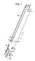
- FIG. 1is a perspective view of a device for delivery of a spinal connection element, such as a spinal rod, to a bone anchor;
- a spinal connection elementsuch as a spinal rod
- FIG. 2is an exploded view of the device of FIG. 1 ;
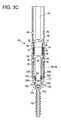
- FIGS. 3A-3Care side views in cross section of the device of FIG. 1 illustrating connection of the device to a bone anchor;
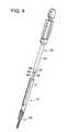
- FIG. 4is a perspective view of the device of FIG. 1 and an instrument for connection and removal of the device to a bone anchor;
- FIGS. 5A and 5Bare side views in cross section of the device of FIG. 1 connected to a bone anchor, illustrating engagement of the instrument of FIG. 4 with the locking member of the device;
- FIGS. 6A-6Dare side views in cross section of the device of FIG. 1 connected to a bone anchor, illustrating engagement of the instrument of FIG. 4 with the annular groove of the inner tube of the device;
- FIGS. 7A and 7Bare side views in cross section of the device of FIG. 1 connected to a bone anchor, illustrating proximal adjustment of the inner tube of the device with the instrument of FIG. 4 ;
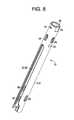
- FIG. 8is a perspective view of another exemplary embodiment of a device for delivery of a spinal connection element, such as a spinal rod, to a bone anchor;
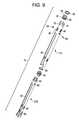
- FIG. 9is an exploded view of the device of FIG. 8 ;
- FIG. 10is a perspective view of another exemplary embodiment of a device for delivery of a spinal connection element, such as a spinal rod, to a bone anchor;
- a spinal connection elementsuch as a spinal rod
- FIG. 11is an exploded view of the device of FIG. 10 ;
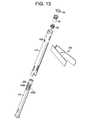
- FIG. 12is a perspective view of another exemplary embodiment of a device for delivery of a spinal connection element, such as a spinal rod, to a bone anchor and of an instrument for removing the inner tube of the device from the outer tube of the device;
- a spinal connection elementsuch as a spinal rod
- FIG. 13is an exploded view of the device of FIG. 12 ;
- FIG. 14is a perspective view of the device of FIG. 12 , illustrating removal of the inner tube of the device from the outer tube of the device;
- FIG. 15is a perspective view of the device of FIG. 1 and a reinforcing instrument positionable within the device;
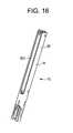
- FIG. 16is a perspective view of the reinforcing instrument of FIG. 15 positioned within the device of FIG. 1 ;
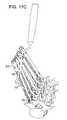
- FIGS. 17A-Dare perspective views of a plurality of devices of FIG. 8 , illustrating delivery of a spinal connection element to a plurality of bone anchors each implanted in a vertebra of the spine.
- an elementmeans one element or more than one element.
- FIGS. 1-7illustrate an exemplary embodiment of a device 10 for delivery of a spinal connection element, such as a rigid or dynamic spinal rod or plate, to a bone anchor.
- the exemplary device 10can facilitate the delivery and implanting of a bone anchor, such as the exemplary bone anchor 100 into bone, in particular, one or more vertebrae of the spine.
- the exemplary device 10can facilitate the delivery and implanting of a bone anchor in a minimally invasive manner and can provide a percutaneous pathway between a skin incision in the patient and the bone anchor that may be used to deliver components of the bone anchor, such as the closure mechanism, one or more spinal connection elements, and/or instruments to the bone anchor.
- the device 10is preferably adapted to be introduced through a minimally invasive percutaneous incision, which is a relatively small incision that typically has a length less than the diameter or width of the device being inserted therethrough.
- the exemplary device 10includes an inner tube 12 and an outer tube 14 disposed about at least a portion of the inner tube 12 .
- the outer tube 14is coaxially disposed about the inner tube 12 such that the inner tube 12 and the outer tube 14 share a common longitudinal axis 26 , 36 .
- the outer tube 14 and inner tube 12need not be coaxially aligned.
- the inner tube 12 and the outer tube 14in the exemplary embodiment, are generally cylindrical in shape, having an approximately circular cross-section.
- the inner tube 12 and the outer tube 14may have other cross-sectional shapes, including, for example, elliptical or rectilinear.
- the inner tube 12 and outer tube 14have analogous cross-sections, however, one skilled in the art will appreciate the inner tube 12 and the outer tube 14 can have different cross-sectional shapes.
- the axial length of the inner tube 12 and outer tube 12may vary depending on, for example, the patient anatomy, the procedures employed, and/or, that area of the spine in which the device 10 is employed.
- the inner tube 12 and the outer tube 14may be linear, as in the exemplary embodiment, or may curved or angled along one or more sections or the entire length thereof.
- the inner tube 12 and the outer tube 14may be constructed from any suitable biocompatible material, including, for example, a metal, such as stainless steel, or a polymer, from any conventional method of manufacturing medical devices.
- the illustrated exemplary embodimentincludes an inner tube and an outer tube, one skilled in the art will appreciate that any number of additional tubes may be employed depending on, for example, the type of bone anchor employed and the manner by which the device is releasably engaged to the bone anchor.
- the inner tube 12includes a proximal end 20 , a distal end 22 , and a lumen 24 extending between the proximal end 20 and the distal end 22 .
- the lumen 24extends the length of the inner tube 12 and defines a longitudinal axis 26 of the inner tube 12 .
- the outer tube 14includes a proximal end 30 , a distal end 32 , and a lumen 34 extending between the proximal end 30 and the distal end 32 .
- the lumen 34may extend the length of the outer tube 14 and defines a longitudinal axis 36 of the outer tube 14 .
- the inner tube 12in positionable within the lumen 34 of the outer tube 14 and, in the exemplary device 10 , the inner tube 12 is longitudinally adjustable with respect to the outer tube 14 between a proximal first position in which the distal end 22 of the inner tube 12 is spaced from the bone anchor and a distal second position in which the distal end 22 of the inner tube 12 contacts the bone anchor.
- the inner tube 12 of the exemplary device 10is truncated compared to the outer tube 14 of the device 10 and is positioned within the distal end 22 of the outer tube 14 .
- the inner tube 12may have one or more sidewall openings or slots 60 formed therein.
- the inner tube 12includes two opposed slots 60 that extend longitudinally from the distal end 22 of the inner tube 12 .
- the outer tube 14may have one or more sidewall openings or slots 62 formed therein.
- the outer tube 14includes two opposed slots 62 that extend longitudinally from the distal end 32 of the inner tube 12 .
- the slots 60 and 62can be used to facilitate positioning of a spinal connection element, such as a rigid or dynamic spinal rod or a plate, relative to one or more bone anchors.
- the slots 60 and the slots 62are preferably aligned with one another along at least a portion of the longitudinal axis of the percutaneous access device 10 .
- the width and length of the slot 60 and slot 62may be varied depending on the particular methods, instruments, and connection elements being employed. In one exemplary embodiment illustrated in FIGS. 8 and 9 and discussed in more detail below, for example, the length of the slots 60 and 62 is selected to span at least from the skin incision to the distal end of the inner tube 12 and the outer tube 14 , respectively. In such embodiments, the slots 60 and 62 may be accessible from outside of the patient.
- the length of the slots 60 and 62is selected to span from the distal end of the inner tube 12 and the outer tube 14 , respectively, to a point distal to the skin incision.
- the slots 60 and 62may be accessible only from the lumens of the inner and outer tubes.
- the slots 60 , 62need not be similarly sized (width and/or length).
- the one or more slots 60may be sized differently than the one or more slots 62
- the one or more of the slots 60 on the inner tubemay be sized differently than other slots 60
- one or more of the slots 62 on the outer tubemay be sized differently than other slots 62 .
- the exemplary embodimentincludes two opposing slots on the inner tube 12 and the outer tube 14 , respectively, one skilled in the art will appreciate that any number of slots may be provided, e.g., no slots, one, two, three, etc. slots, may be provided depending on the method, instruments, and/or connection element employed.
- the outer tube 14 of the device 10may include proximal slots 66 A-B that are open at proximal end 30 of the outer tube 14 and extend distally from the proximal end 30 of the outer tube 14 .
- the proximal slots 66 A-Bfacilitate pivoting of the spinal rod in position relative to the bone anchor by accommodating a rod delivery instrument.
- the distal end 32 of the outer tube 14may include a plurality of instrument engagement features to facilitate engagement of an instrument, such as a reduction instruments or a compression/distraction instrument, to the device 10 .
- the instrument engagement featuresmay be a plurality of flat surfaces provided at spaced apart locations on the outer surface of the outer tube 12 .
- the instrument engagement featuresmay be one or more openings 78 provided at spaced apart locations on the outer surface of the outer tube 12 .
- the instrument engagement featuresare a pair of diametrically opposed openings 78 .
- the inner tube 12 and the outer tube 14may include a plurality of cleaning openings 86 therein to facilitate cleaning of the device 10 .
- the device 10is preferably releasably engageable to a bone anchor.
- the outer tube 14may be releasably engaged to a bone anchor, such as bone anchor 100 .
- the outer tube 14may be engaged to a bone anchor in a manner that allows the device 10 to be connected to the bone anchor 100 during use, e.g., during implantation and/or delivery and/or fastening of a spinal connection element to the bone anchor, and allows the device to be disconnected from the bone anchor 100 at the conclusion of the procedure.
- the device 10can be disconnected remotely.
- the device 10can be disconnected from the bone anchor by accessing the lumen 34 of the outer tube 14 of the device 10 from the proximal end 30 of the outer tube 14 , as discussed in more detail below.
- the distal end 32 of the outer tube 14includes a pair of opposed longitudinally extending tabs 70 A and 70 B that may releaseable engage a bone anchor.
- the tabs 70 A and 70 Bare defined by the sidewalls of the outer tube 14 and are separated by slots 62 .
- the tabs 70 A and 70 Bmay be flexible and resilient in the radial direction to facilitate connection to a bone anchor.
- the tabs 70 A and 70 Bmay be flexed apart in the radial direction from a first, relaxed position to facilitate advancement of the tabs longitudinally over a portion of the bone anchor.
- the tabs 70 A and 70 Bmay provide a radially compressive force on the bone anchor as the tabs 70 A and 70 B attempt to return to the first, relaxed position.
- the tabs 70 A and 70 Bneed not be flexible and resilient.
- the tabs 70 A and 70 Beach may include a distal angled surface 71 A and 71 B to facilitate positioning of the tabs 70 A and 70 B about the bone anchor.
- the distal angled surfaces 71 A and 71 Bextend from a radially outward, distal end to a radially inward, proximal end. In this orientation, the distal angled surfaces 71 A and 71 B act to separate the tabs 70 A and 70 B during distal advancement of the outer tube 14 about the bone anchor.
- each tab 70 A and 70 Bmay include one or more radially inward facing projection 72 A, 72 B for engagement with a connection feature on a bone anchor.
- the projection 72 A, 72 Bmay be sized and shaped to seat within an opening provided in a portion of the bone anchor.
- the size, shape and number of projectionscan be varied depending on, for example, the opening(s) provided on the bone anchor and type of connection desired.
- each projection 72 A, 72 Bis generally arcuate in shape and has a cross section that is complementary to an arcuate groove 130 provided in the spinal connection element receiving member 108 of the exemplary bone anchor 100 . Exemplary configurations for the projections and the corresponding connection features on the bone anchor are described in U.S. Patent Application Publication No. 2005/0131408, which is incorporated herein by reference.
- the distal end 22 of the inner tube 12may include a contact surface 81 that contacts at least a portion of a bone anchor when the inner tube 12 is adjusted relative to the outer tube 14 to the second position in which the inner tube 12 contacts the bone anchor.
- the distal end 22 of the inner tube 12may have two opposing generally arcuate contact surfaces 81 .
- the contact surfaces 81in the exemplary embodiment, are oriented approximately perpendicular to the longitudinal axis of the inner tube 12 .
- the contact surfaces 81are configured to contact a generally arcuate contact surface provided on the proximal end of the receiving member of the exemplary bone anchor 100 .
- each contact surface 81is complementary in size, shape, and orientation to the contact surface on the bone anchor.
- the configuration of the contact surface 81e.g., number, size, shape, and orientation of the contact surface 81 , may be varied to, for example, suit the bone anchor being employed.
- the distal end 22 of the inner tube 12 and/or the distal end 32 of the outer tube 14may be configured to inhibit rotation of the bone anchor relative to the device 10 .
- the distal end 22 of the inner tubemay include one or more finger-like extensions 82 that extend approximately axially from the distal end 22 of the inner tuber 12 and engage a bone anchor to inhibit rotation of the bone relative to the device.
- one or more of the extensions 82may seat within a groove, recess, slot, or similar structure provided in the bone anchor. These extensions 82 also extend radially outward, straddling outer tube 14 and rotationally coupling them.
- the device 10may include a spring 50 positioned within the outer tube 14 and interposed between the inner tube 12 and the outer tube 14 to bias the inner tube 12 distally to, for example, the second position.
- the spring 50may be interposed between the inner tube 12 and a shoulder 52 provided on an inner surface of the outer tube 14 .
- a washer 54may be interposed between the spring 50 and the shoulder 52 , as in the exemplary embodiment, or the spring 50 may directly contact the shoulder 50 .
- the spring 50may be positioned about a portion of the inner tube 12 , for example the proximal end 20 of the inner tube 12 , and may engage a shoulder 56 on an outer surface of the inner tube 14 .
- the springis positioned about the proximal end 20 of the inner tube 12 , a distal end of the spring 50 abuts the shoulder 56 on the inner tube 12 , and a proximal end of the spring 50 abuts the washer 54 interposed between the spring 50 and the shoulder 52 on the outer tube 14 .
- the device 10may include one or more mechanisms to oppose the spring force from the spring 50 and to retain the inner tube 12 within the outer tube 14 .
- the mechanismsmay include, for example, one or more retaining slots 58 oriented along the longitudinal axis of the inner tube 12 each of which receives a projection 59 , such as a pin or the like, from an inner surface of the outer tube 14 .
- the length of the retaining slot 58may be selected to provide the desired extent or limit of longitudinal adjustment of the inner tube 12 relative to the outer tube 14 .
- a pair of diametrically opposed retaining slots 58are provided although any number of slots may be provided.
- the retaining slot 58 and the projection 59 received within the retaining slotmay also inhibit relative rotation of the inner tube 12 and outer tube 14 .
- Other mechanisms for retaining the inner tube 12may include the radial inward projections 72 A and 72 B.
- the distal end 22 of the inner tube 12is biased by the spring 50 into abutment with each of the projections 72 A and 72 B.
- the device 10may include a locking member 90 coupled to the outer tube 14 and adjustable relative to the outer tube 14 along the longitudinal axis of the outer tube 14 between a proximal position in which the locking member 90 is spaced apart from the inner tube 12 to permit proximal axial movement of the inner tube 12 relative to the outer tube 14 and a distal position in which the locking member 90 inhibits proximal axial motion of the inner tube 12 relative to the outer tube 14 .
- the locking member 90may be positioned within the lumen 34 of the outer tube 14 , as in the exemplary embodiment, or may be external to the outer tube 14 .
- the locking member 90includes external threads 92 that engage internal threads 94 provided within the outer tube 14 .
- the locking member 90may include one or more instrument engagement features 96 to facilitate adjustment of the locking member 90 with an instrument.
- the locking member 90is a castle nut.
- On or more retaining pins 68may be positioned within an opening in the outer tube 14 and may extend into the inner tube 12 to engage the locking member 90 and retain the locking member 90 within the outer tube 14 .
- FIGS. 3A-3Cillustrate an exemplary embodiment of a bone anchor 100 that is particularly suited for use with the exemplary device 10 described herein.
- exemplary bone anchor 100includes a bone screw 102 , such as a pedicle screw, having a proximal head 104 and a distal bone engaging portion 106 , which in the illustrated exemplary embodiment is an externally threaded screw shank.
- the exemplary bone screw assembly 100also includes a receiving member 108 that is configured to receive and couple a spinal connection element, such as a spinal rod or spinal plate, to the bone anchor 100 .
- the receiving member 108may be coupled to the bone anchor 102 in any well-known conventional manner.
- the bone anchormay be poly-axial, as in the present exemplary embodiment in which the bone anchor 102 may be adjustable to multiple angles relative to the receiving member 108 , or the bone anchor may be mono-axial, e.g., the bone anchor 102 may fixed relative to the receiving member 108 .
- Exemplary poly-axial bone screwsare the EXPEDIUM Polyaxial Pedicle Screws and the VIPER Polyaxial Pedicle Screws, which are available from DePuy Spine, Inc. of Raynham, Mass.
- the receiving member 108 of the illustrated exemplary embodimentincludes a proximal end 110 , a distal end 112 , and a recess or slot 114 for receiving a spinal connection element such as a spinal rod.
- the receiving member 108has a generally U-shaped cross-section defined by two legs 124 A and 124 B separated by recess 114 . Each leg 124 A, 124 B is free at the proximal end 110 of the receiving member 108 .
- the receiving member 108may be configured to receive a closure mechanism that locks a spinal connection element within the recess 114 .
- the closure mechanismmay be a set screw that is advanceable through the receiving member 108 and may directly or indirectly engage the spinal connection element.
- the closure mechanismmay have external threads that engage internal threads 148 provided in the receiving member 108 , e.g., on the legs 124 A,B, as in the exemplary embodiment.
- Any type of conventional closure mechanismmay be employed, including, for example, set-screws, non-threaded caps, multi-component closure mechanisms, and/or external nuts.
- FIGS. 3A-3Bfurther illustrate an exemplary method of connecting the device 10 to the bone anchor 100 .
- FIG. 3Aillustrates the device 10 prior to connection to the bone anchor 100 .
- the locking member 90is in a proximal position in which the locking member 90 is spaced apart from the proximal end 20 of the inner tube 12 and the inner tube 12 may be adjusted relative to the outer tube 14 .
- the spring 50biases the inner tube 12 distally into abutment with the proximal surfaces of the projections 72 A, 72 B of each of the tabs 70 A, 70 B of the outer tube 14 .
- FIG. 3Billustrates the outer tube 14 of the device 10 connected to the bone anchor 100 .
- the distal end 32 of the outer tube 14is advanced over the proximal end of the receiving member 108 of the bone anchor 100 .
- the angled surfaces 71 A and 71 Bcontact the proximal surface of the receiving member 108 of the bone anchor and cause the tabs 70 A and 70 B to flex apart thereby facilitating connection of the outer tube 14 to the bone anchor 100 .
- the contact surfaces 81 on the distal end 22 of the inner tube 12engage the proximal end of the receiving member 108 of the bone anchor 100 and the inner tube 12 is moved proximally relative to the outer tube 12 in opposition to the spring force from the spring 50 .
- Advancement of the outer tube 14may continue until the projections 72 A and 72 B are seated within the arcuate grooves 130 of the receiving member 108 of the bone anchor 100 .
- the spring force from spring 50maintains the contact surfaces 81 on the distal end 22 of the inner tube 12 in engagement with the proximal end of the receiving member 108 of the bone anchor 100 thereby providing a provisional connection of the device 10 to the bone anchor 100 .
- the locking member 90is in a proximal position in which the locking member 90 is spaced apart from the inner tube 12 to permit proximal axial movement of the inner tube 12 relative to the outer tube 14 . As the inner tube 12 remains adjustable relative to the outer tube 14 , the device 10 may be easily removed from the bone anchor 100 .
- FIG. 3Cillustrates the device 10 locked to the bone anchor 100 .
- the locking member 90is adjusted relative to the inner tube 12 to inhibit proximal movement of the inner tube 12 relative to the outer tube 14 and thereby lock the device 10 firmly to the bone anchor 100 .
- the locking member 90is advanced within the lumen 34 of the outer tube 14 to a distal position in which the locking member 90 abuts the proximal end 20 of the inner tube 12 and inhibits proximal axial motion of the inner tube 12 relative to the outer tube 14 .
- the device 10may be connected to the exemplary bone anchor 100 , or another bone anchor, before implantation of the bone anchor or after the bone anchor is implanted into the patient's body.
- the device 10may provide a percutaneous pathway between a skin incision and the bone anchor 100 that facilitates delivery of instruments, spinal connection elements, and/or components of the bone anchor, such as the closure mechanism, to the bone anchor 100 .
- the lumen 24 of the inner tube 12provides a pathway to the receiving member 108 of the bone anchor 100 , that may allow a closure mechanism, such as a set screw, to be delivered to the receiving member 108 of the bone anchor and/or may allow a screw driver or the like to be advanced into engagement with the head 104 of the bone anchor 102 .
- the slots 60 of the inner tube and the slots 62 of the outer tube 14may be aligned with the recess 114 provided in the receiving member 108 . Alignment of the slots 60 and 62 with the recess 114 facilitates the delivery of a spinal connection element to the bone anchor 100 , as described below. Further exemplary methods and devices for delivering a spinal connection element to a bone anchor are described in U.S. Patent Application Publication No. 2005/0131421 and U.S. Patent Application Publication No. 2005/0131422, each of which are incorporated herein by reference.
- an exemplary instrument 150 for adjusting the locking member 90 relative to the inner tube 12 and for adjusting the inner tube 12 relative to the outer tube 14is illustrated.
- the exemplary instrument 150includes an inner sleeve 152 and an outer sleeve 154 positioned about at least a portion of the inner sleeve 152 and coaxial disposed with respect to the inner sleeve 152 .
- the inner sleeve 152may be axially adjustable relative to the outer sleeve 154 or may be fixed relative to the outer sleeve 154 , as in the exemplary embodiment.
- the outer sleeve 154may be rotationally adjustable relative to the inner sleeve 152 , as in the exemplary embodiment, or may be fixed relative to the inner sleeve 152 such that the outer sleeve 154 and inner sleeve 152 rotate together.
- the distal end 156 of the outer sleeve 154may include one or more drive features 158 for engagement with the locking member 90 to adjust the locking member 90 within the outer tube 14 into and out of engagement with the inner tube 12 .
- the distal end 160 of the inner sleeve 152extends from the distal end 156 of the outer sleeve 154 and has one or more projections 162 engageable with an instrument engagement feature provided on the inner tube 12 of the device 10 .
- the instrument engagement feature in the exemplary embodimentis an annular groove 164 provided within the lumen 24 of the inner tube 12 .
- the instrument engagement featuremay be one or more slots, openings, projections, or other known structures for engaging an instrument to another instrument or to an implant.
- the distal end 160 of the inner sleeve 152 of the instrument 150may be a pair of spaced apart prongs 166 A and 166 B, each prong 166 A,B may include a projection 162 for engagement with the instrument engagement feature, e.g., the annular groove 164 , of the inner tube 12 .
- the instrument 150may further include a central shaft 168 positionable coaxially within the inner sleeve 152 and adjustable with respect to the inner sleeve 152 .
- Distal advancement of the central shaft 168 relative to the inner sleeve 152may cause radial deployment of the prongs 166 A and 166 B, and the respective projections 162 , from a parallel position to a non-parallel position in which the prongs 166 A and 166 B are spaced further apart from one another.
- FIGS. 5A-7Ban exemplary method of operation of the exemplary instrument 150 is illustrated.
- FIGS. 5A and 5Billustrate engagement of the instrument 150 with the locking member 90 of the device 10 .
- the distal end 156 of the outer sleeve 154is positioned within the lumen 34 of the outer tube 14 and advanced distally until the drive features 158 engage the drive features provided on the locking member 90 .
- the outer sleeve 154 of the instrument 150may be rotated with respect to the outer tube 14 and the inner tube 12 to move the locking member 90 distally into engagement with the proximal end 20 of the inner tube 12 , as illustrated in FIGS. 6A and 6B .
- the projections 162 of the inner sleeve 152are axially aligned with the annular groove 164 of the inner tube 12 , as illustrated in FIGS. 6A and 6B .
- the instrument 150may then be removed to permit delivery of a spinal connection element or other implants or instruments to the bone anchor 100 .
- the instrument 150may be reinserted into the device 10 .
- the central shaft 168 of the instrument 150may be advanced distally relative to the inner sleeve 152 to cause radial deployment of the prongs 166 A and 166 B, and the respective projections 162 , from a parallel position ( FIGS. 6A and 6B ) to a non-parallel position in which the prongs 166 A and 166 B are spaced further apart from one another and the projections 162 are positioned within the annular groove 164 , as illustrated in FIGS. 6C and 6D .
- the outer sleeve 154 of the instrument 150may be rotated to adjust the locking member 90 proximally away from the proximal end 20 of the inner tube 12 .
- the inner sleeve 152 of the instrument 150adjusts the inner tube 12 of the device 10 proximally, against the spring force provided by spring 50 , such that the distal end 22 of the inner tube 12 is spaced apart from the proximal end of the receiving member 108 of the bone anchor 100 ( FIGS. 7A and 7B ), thereby facilitating removal of the device 10 from the bone anchor 100 .
- adjustment of the locking member 90 proximally and adjustment of the inner tube 12may occur in discrete separate steps.
- FIGS. 8 and 9illustrate another embodiment of an exemplary device 210 that is analogous in construction in operation to the device 10 illustrated above.
- the length of the inner tube 212 of the device 210is approximate the length of the outer tube 214 of the device 210 .
- the length of the slots 60 and 62is selected to span at least from the skin incision to the distal end of the inner tube 212 and the outer tube 214 , respectively.
- the slots 60 and 62may be accessible from outside of the patient.
- the outer tube 214 of the device 210includes a pair of diametrically opposed flat surfaces 76 and a pair of diametrically opposed openings, in the form of slots 78 , to facilitate engagement of the outer tube 214 with an instrument.
- a cap 95may be positioned at the proximal end of the outer tube 214 to inhibit removal of the locking member 90 from the within the outer tube 214 .
- FIGS. 17A-17Dillustrate an exemplary methods of delivering a spinal connection element, e.g., a spinal rod 140 , to one or more bone anchors 100 using the exemplary device 210 .
- the exemplary method described hereinis a multi-level procedure in which a bone anchor 100 is implanted in a plurality, five, adjacent vertebrae and a spinal rod 140 is delivered to the each of the bone anchors 100 to connect the bone anchors and provide stability to the vertebrae until fusion of the vertebrae occur.
- the exemplary methodmay be employed to instrument any number of spine levels, from a single level (two vertebrae) to multiple levels (three or more vertebrae).
- each bone anchor 100may be connected to a device, such as device 10 or device 210 , in the manner described above.
- the bone anchors 100may be implanted in a vertebra through a single open incision or, more preferably, each bone anchor 100 and its respective device 210 are delivered through a separate minimally invasive stab incision in the patient to proximate a vertebra of the patient, as illustrated in FIG. 17A .
- a spinal rod 140may be advanced through the stab incision used for the bone anchor 100 and through at least a portion of the device 210 to the bone anchor 100 .
- the spinal rod 100may be advance to the bone anchor 100 by pivoting the spinal rod 140 sub-dermally (i.e., beneath the skin) from a first orientation to a second orientation substantially parallel to the axis of the spine of the patient, as illustrated in FIGS. 17B-17D .
- a rod delivery instrument 180may be employed to manipulate the spinal rod 140 .
- the spinal rod 140In the first orientation, the spinal rod 140 may be oriented substantially parallel to or at an angle to the device 210 .
- the leading end of the spinal rod 140 and at least a portion of the length of the spinal rod 140may pass through the slots 60 and 62 of one or more of the devices 210 .
- the spinal rod 140may be inserted through the same incision as the device 210 and the bone anchor 100 either through the lumen of the inner tube 212 of the device 210 or external to the device 210 (but still through the same incision of the device 210 ), as illustrated in FIG. 17B .
- the spinal rod 140may be connected to each of the bone anchors by a closure mechanism, which may delivered to the bone anchor through the device 10 .
- Each device 210may then be removed its respective bone anchor 100 .
- FIGS. 10 and 11illustrate another embodiment of an exemplary device 310 that is analogous in construction in operation to the device 10 illustrated above.
- the device 310includes a first sliding member 302 A connected through one or more openings 304 A in the outer tube 314 to the inner tube 312 to permit adjustment of the inner tube 312 relative to the outer tube 314 .
- the device 310may further include additional sliding members, such as a second sliding member 302 B connected through one or more second openings 304 B in the outer tube 314 to the inner tube 312 .
- the second sliding member 302 Bmay be positioned diametrically opposite the first sliding member 302 B or at other suitable locations.
- Proximal adjustment of the sliding members 302 A and 30 Bcause the inner tube to be adjusted proximally relative to the outer tube 314 , in opposition to the spring force provided by the spring 50 , to facilitate release of the device 310 from a bone anchor without the need for a separate instrument, such as instrument 150 described above.
- FIGS. 12-14illustrate another embodiment of an exemplary device 410 that is analogous in construction in operation to the device 10 illustrated above.
- the inner tube 412is removable and replaceable from the outer tube 414 to facilitate cleaning of the inner tube 412 .
- the inner tube 414may include a pair of adjustable prongs 406 A and 406 B each of which is connected to the inner tube 412 at a first end.
- Each prong 406 A and 406 Bmay have a free end opposite the first end having a projection 408 positioned thereon.
- the prongs 406 A and 406 Bmay be biased to a first position in which the projection 408 is received in an opening 409 in the outer tube 414 and may be adjustable to a second position in which the projection 408 is removed from the opening 408 to facilitate removal of the inner tube 412 from the outer tube 414 for cleaning.
- An instrument 494may be provided to adjust the prongs to the second position.
- the instrument 494may include a pair of jaw members 496 A and 496 B having projections 498 A and 498 B sized and shaped to fit within the openings 409 to engage the projections 408 on the prongs 406 A and 406 B and adjust the prongs 406 A and 406 B to the second position.
- FIGS. 15 and 16illustrate a reinforcing instrument 501 that may be positioned within the device 10 or the other devices described herein.
- the reinforcing instrument 501is generally cylindrical in shape and, in the exemplary embodiment, is sized to fit within the lumen of the outer tube 14 of the device 10 to provide stability to the outer tube 14 and to inhibit collapse of the proximal end 30 of the outer tube 14 during manipulation of the device 10 .
- the instrument 501may have a cross-sectional extent, e.g., a diameter, approximately equal to the cross-section extent of the outer tube 14 .
- the length of the reinforcing instrument 501may be approximately equal to the length of the proximal slots 66 .
Landscapes
- Health & Medical Sciences (AREA)
- Orthopedic Medicine & Surgery (AREA)
- Neurology (AREA)
- Life Sciences & Earth Sciences (AREA)
- Surgery (AREA)
- Heart & Thoracic Surgery (AREA)
- Engineering & Computer Science (AREA)
- Biomedical Technology (AREA)
- Nuclear Medicine, Radiotherapy & Molecular Imaging (AREA)
- Medical Informatics (AREA)
- Molecular Biology (AREA)
- Animal Behavior & Ethology (AREA)
- General Health & Medical Sciences (AREA)
- Public Health (AREA)
- Veterinary Medicine (AREA)
- Surgical Instruments (AREA)
Abstract
Description
Claims (16)
Priority Applications (1)
| Application Number | Priority Date | Filing Date | Title |
|---|---|---|---|
| US12/244,268US8414588B2 (en) | 2007-10-04 | 2008-10-02 | Methods and devices for minimally invasive spinal connection element delivery |
Applications Claiming Priority (2)
| Application Number | Priority Date | Filing Date | Title |
|---|---|---|---|
| US97749007P | 2007-10-04 | 2007-10-04 | |
| US12/244,268US8414588B2 (en) | 2007-10-04 | 2008-10-02 | Methods and devices for minimally invasive spinal connection element delivery |
Publications (2)
| Publication Number | Publication Date |
|---|---|
| US20090143828A1 US20090143828A1 (en) | 2009-06-04 |
| US8414588B2true US8414588B2 (en) | 2013-04-09 |
Family
ID=40676527
Family Applications (1)
| Application Number | Title | Priority Date | Filing Date |
|---|---|---|---|
| US12/244,268Active2030-01-02US8414588B2 (en) | 2007-10-04 | 2008-10-02 | Methods and devices for minimally invasive spinal connection element delivery |
Country Status (1)
| Country | Link |
|---|---|
| US (1) | US8414588B2 (en) |
Cited By (12)
| Publication number | Priority date | Publication date | Assignee | Title |
|---|---|---|---|---|
| US20110060344A1 (en)* | 2003-12-16 | 2011-03-10 | Christopher Sicvol | Percutaneous Access Devices And Bone Anchor Assemblies |
| US20120271365A1 (en)* | 2008-12-17 | 2012-10-25 | Synthese USA, LLC | Rod reducer apparatus for spinal corrective surgery |
| US20130018418A1 (en)* | 2009-12-28 | 2013-01-17 | Safe Orthopaedics | Device and method for spinal surgery |
| US20140277151A1 (en)* | 2013-03-15 | 2014-09-18 | DePuy Synthes Products, LLC | Fulcrum Cap for Spinal Constructs |
| US20140336709A1 (en)* | 2013-03-13 | 2014-11-13 | Baxano Surgical, Inc. | Multi-threaded pedicle screw system |
| US20160331419A1 (en)* | 2015-05-12 | 2016-11-17 | Lutz Biedermann | Instrument for use with a polyaxial bone anchoring device and system including the instrument and a polyaxial bone anchoring device |
| US9750546B2 (en) | 2014-08-11 | 2017-09-05 | Spinal Elements, Inc. | Articulating rod inserter |
| US9844398B2 (en) | 2012-05-11 | 2017-12-19 | Orthopediatrics Corporation | Surgical connectors and instrumentation |
| US20190046240A1 (en)* | 2017-08-08 | 2019-02-14 | Biedermann Technologies Gmbh & Co., Kg. | Receiving part and instrument for holding the receiving part |
| US10779866B2 (en) | 2016-12-29 | 2020-09-22 | K2M, Inc. | Rod reducer assembly |
| USD951453S1 (en)* | 2020-09-03 | 2022-05-10 | Solco Biomedical Co., Ltd. | Spinal screw for minimally invasive surgery |
| US11419642B2 (en) | 2003-12-16 | 2022-08-23 | Medos International Sarl | Percutaneous access devices and bone anchor assemblies |
Families Citing this family (112)
| Publication number | Priority date | Publication date | Assignee | Title |
|---|---|---|---|---|
| US7833250B2 (en) | 2004-11-10 | 2010-11-16 | Jackson Roger P | Polyaxial bone screw with helically wound capture connection |
| US7862587B2 (en) | 2004-02-27 | 2011-01-04 | Jackson Roger P | Dynamic stabilization assemblies, tool set and method |
| US8876868B2 (en) | 2002-09-06 | 2014-11-04 | Roger P. Jackson | Helical guide and advancement flange with radially loaded lip |
| US9539012B2 (en) | 2002-10-30 | 2017-01-10 | Zimmer Spine, Inc. | Spinal stabilization systems with quick-connect sleeve assemblies for use in surgical procedures |
| AU2003287273C1 (en) | 2002-10-30 | 2010-01-07 | Zimmer Spine, Inc. | Spinal stabilization system insertion and methods |
| US7887539B2 (en) | 2003-01-24 | 2011-02-15 | Depuy Spine, Inc. | Spinal rod approximators |
| US7988698B2 (en) | 2003-01-28 | 2011-08-02 | Depuy Spine, Inc. | Spinal rod approximator |
| US7621918B2 (en) | 2004-11-23 | 2009-11-24 | Jackson Roger P | Spinal fixation tool set and method |
| US7377923B2 (en) | 2003-05-22 | 2008-05-27 | Alphatec Spine, Inc. | Variable angle spinal screw assembly |
| US7776067B2 (en) | 2005-05-27 | 2010-08-17 | Jackson Roger P | Polyaxial bone screw with shank articulation pressure insert and method |
| US8926670B2 (en) | 2003-06-18 | 2015-01-06 | Roger P. Jackson | Polyaxial bone screw assembly |
| US7766915B2 (en) | 2004-02-27 | 2010-08-03 | Jackson Roger P | Dynamic fixation assemblies with inner core and outer coil-like member |
| US8366753B2 (en) | 2003-06-18 | 2013-02-05 | Jackson Roger P | Polyaxial bone screw assembly with fixed retaining structure |
| US7967850B2 (en) | 2003-06-18 | 2011-06-28 | Jackson Roger P | Polyaxial bone anchor with helical capture connection, insert and dual locking assembly |
| US7527638B2 (en) | 2003-12-16 | 2009-05-05 | Depuy Spine, Inc. | Methods and devices for minimally invasive spinal fixation element placement |
| ATE441376T1 (en) | 2003-12-17 | 2009-09-15 | Depuy Spine Inc | INSTRUMENTS AND PROCEDURES FOR BONE ANCHOR PROCEDURES AND SPINAL BAR REDUCTION |
| US7842044B2 (en)* | 2003-12-17 | 2010-11-30 | Depuy Spine, Inc. | Instruments and methods for bone anchor engagement and spinal rod reduction |
| US11241261B2 (en) | 2005-09-30 | 2022-02-08 | Roger P Jackson | Apparatus and method for soft spinal stabilization using a tensionable cord and releasable end structure |
| US8152810B2 (en) | 2004-11-23 | 2012-04-10 | Jackson Roger P | Spinal fixation tool set and method |
| US7160300B2 (en) | 2004-02-27 | 2007-01-09 | Jackson Roger P | Orthopedic implant rod reduction tool set and method |
| JP2007525274A (en) | 2004-02-27 | 2007-09-06 | ロジャー・ピー・ジャクソン | Orthopedic implant rod reduction instrument set and method |
| US8926672B2 (en) | 2004-11-10 | 2015-01-06 | Roger P. Jackson | Splay control closure for open bone anchor |
| US8444681B2 (en) | 2009-06-15 | 2013-05-21 | Roger P. Jackson | Polyaxial bone anchor with pop-on shank, friction fit retainer and winged insert |
| US9168069B2 (en) | 2009-06-15 | 2015-10-27 | Roger P. Jackson | Polyaxial bone anchor with pop-on shank and winged insert with lower skirt for engaging a friction fit retainer |
| WO2006057837A1 (en) | 2004-11-23 | 2006-06-01 | Jackson Roger P | Spinal fixation tool attachment structure |
| US7901437B2 (en) | 2007-01-26 | 2011-03-08 | Jackson Roger P | Dynamic stabilization member with molded connection |
| US7951172B2 (en) | 2005-03-04 | 2011-05-31 | Depuy Spine Sarl | Constrained motion bone screw assembly |
| US7951175B2 (en) | 2005-03-04 | 2011-05-31 | Depuy Spine, Inc. | Instruments and methods for manipulating a vertebra |
| US20060293692A1 (en) | 2005-06-02 | 2006-12-28 | Whipple Dale E | Instruments and methods for manipulating a spinal fixation element |
| US8560047B2 (en) | 2006-06-16 | 2013-10-15 | Board Of Regents Of The University Of Nebraska | Method and apparatus for computer aided surgery |
| US8211110B1 (en)* | 2006-11-10 | 2012-07-03 | Lanx, Inc. | Minimally invasive tool to facilitate implanting a pedicle screw and housing |
| CA2670988C (en) | 2006-12-08 | 2014-03-25 | Roger P. Jackson | Tool system for dynamic spinal implants |
| US8172847B2 (en) | 2007-03-29 | 2012-05-08 | Depuy Spine, Inc. | In-line rod reduction device and methods |
| US8979904B2 (en) | 2007-05-01 | 2015-03-17 | Roger P Jackson | Connecting member with tensioned cord, low profile rigid sleeve and spacer with torsion control |
| US7887541B2 (en)* | 2007-07-26 | 2011-02-15 | Depuy Spine, Inc. | Spinal rod reduction instruments and methods for use |
| US8790348B2 (en) | 2007-09-28 | 2014-07-29 | Depuy Spine, Inc. | Dual pivot instrument for reduction of a fixation element and method of use |
| WO2009055026A1 (en)* | 2007-10-23 | 2009-04-30 | Alphatec Spine, Inc. | Systems and methods for spinal fixation |
| DE102007052173B4 (en)* | 2007-10-30 | 2012-01-12 | Kilian Kraus | Handling tool for a medical implant |
| US8439922B1 (en)* | 2008-02-06 | 2013-05-14 | NiVasive, Inc. | Systems and methods for holding and implanting bone anchors |
| US8608746B2 (en) | 2008-03-10 | 2013-12-17 | DePuy Synthes Products, LLC | Derotation instrument with reduction functionality |
| US8709015B2 (en)* | 2008-03-10 | 2014-04-29 | DePuy Synthes Products, LLC | Bilateral vertebral body derotation system |
| US10973556B2 (en) | 2008-06-17 | 2021-04-13 | DePuy Synthes Products, Inc. | Adjustable implant assembly |
| AU2010260521C1 (en) | 2008-08-01 | 2013-08-01 | Roger P. Jackson | Longitudinal connecting member with sleeved tensioned cords |
| US8496661B2 (en)* | 2008-11-03 | 2013-07-30 | Omni Surgical LLC | System and method for micro-invasive transfacet lumbar interbody fusion |
| US9750545B2 (en) | 2009-03-27 | 2017-09-05 | Globus Medical, Inc. | Devices and methods for inserting a vertebral fixation member |
| US8900238B2 (en)* | 2009-03-27 | 2014-12-02 | Globus Medical, Inc. | Devices and methods for inserting a vertebral fixation member |
| US8206394B2 (en) | 2009-05-13 | 2012-06-26 | Depuy Spine, Inc. | Torque limited instrument for manipulating a spinal rod relative to a bone anchor |
| US9668771B2 (en) | 2009-06-15 | 2017-06-06 | Roger P Jackson | Soft stabilization assemblies with off-set connector |
| US8998959B2 (en) | 2009-06-15 | 2015-04-07 | Roger P Jackson | Polyaxial bone anchors with pop-on shank, fully constrained friction fit retainer and lock and release insert |
| CN103826560A (en) | 2009-06-15 | 2014-05-28 | 罗杰.P.杰克逊 | Polyaxial Bone Anchor with Socket Stem and Winged Inserts with Friction Fit Compression Collars |
| US11229457B2 (en) | 2009-06-15 | 2022-01-25 | Roger P. Jackson | Pivotal bone anchor assembly with insert tool deployment |
| DE112010004338B4 (en)* | 2009-11-10 | 2019-06-27 | Nuvasive, Inc. | DEVICE FOR IMPLEMENTING SPINE SURGERY |
| US8545505B2 (en)* | 2010-01-15 | 2013-10-01 | Pioneer Surgical Technology, Inc. | Low friction rod persuader |
| US8540719B2 (en)* | 2010-02-09 | 2013-09-24 | Aesculap Implant Systems, Llc | Percutaneous rod insertion system and method |
| CN103097747A (en)* | 2010-04-22 | 2013-05-08 | 蓝带技术有限责任公司 | Attachment mechanism |
| EP2561239A4 (en) | 2010-04-22 | 2014-08-06 | Blue Belt Tech Inc | Navigated freehand surgical tool and kit |
| US8777954B2 (en)* | 2010-06-18 | 2014-07-15 | Spine Wave, Inc. | Pedicle screw extension for use in percutaneous spinal fixation |
| US8512383B2 (en) | 2010-06-18 | 2013-08-20 | Spine Wave, Inc. | Method of percutaneously fixing a connecting rod to a spine |
| US8394108B2 (en) | 2010-06-18 | 2013-03-12 | Spine Wave, Inc. | Screw driver for a multiaxial bone screw |
| US8454664B2 (en) | 2010-06-18 | 2013-06-04 | Spine Wave, Inc. | Method for fixing a connecting rod to a thoracic spine |
| US8206395B2 (en) | 2010-06-18 | 2012-06-26 | Spine Wave, Inc. | Surgical instrument and method for the distraction or compression of bones |
| US8603094B2 (en) | 2010-07-26 | 2013-12-10 | Spinal Usa, Inc. | Minimally invasive surgical tower access devices and related methods |
| US8685029B2 (en) | 2010-09-27 | 2014-04-01 | DePuy Synthes Products, LLC | Rod reduction instrument and methods of rod reduction |
| US9198698B1 (en) | 2011-02-10 | 2015-12-01 | Nuvasive, Inc. | Minimally invasive spinal fixation system and related methods |
| US9307972B2 (en) | 2011-05-10 | 2016-04-12 | Nuvasive, Inc. | Method and apparatus for performing spinal fusion surgery |
| US9498231B2 (en) | 2011-06-27 | 2016-11-22 | Board Of Regents Of The University Of Nebraska | On-board tool tracking system and methods of computer assisted surgery |
| US11911117B2 (en) | 2011-06-27 | 2024-02-27 | Board Of Regents Of The University Of Nebraska | On-board tool tracking system and methods of computer assisted surgery |
| CN103764061B (en) | 2011-06-27 | 2017-03-08 | 内布拉斯加大学评议会 | On Tool Tracking System and Computer Assisted Surgery Method |
| US9204909B2 (en)* | 2011-07-13 | 2015-12-08 | Warsaw Orthopedic, Inc. | Spinal rod system and method |
| US9289250B2 (en)* | 2011-10-17 | 2016-03-22 | Warsaw Orthopedic, Inc. | Extender collar system |
| US8911479B2 (en) | 2012-01-10 | 2014-12-16 | Roger P. Jackson | Multi-start closures for open implants |
| US9125703B2 (en)* | 2012-01-16 | 2015-09-08 | K2M, Inc. | Rod reducer, compressor, distractor system |
| US20150066042A1 (en)* | 2012-01-25 | 2015-03-05 | Spinal Usa, Inc. | Minimally invasive devices and methods for delivering fixation devices and implants into a spine |
| US8936626B1 (en) | 2012-02-17 | 2015-01-20 | Nuvasive, Inc. | Bi-cortical screw fixation |
| US9078709B2 (en) | 2012-03-19 | 2015-07-14 | Warsaw Orthopedic, Inc. | Spinal implant system and method |
| US9220539B2 (en) | 2012-03-19 | 2015-12-29 | Warsaw Orthopedic, Inc. | Spinal implant system and method |
| US8439924B1 (en)* | 2012-04-02 | 2013-05-14 | Warsaw Orthopedic, Inc. | Spinal implant system and method |
| US9451998B2 (en) | 2012-08-17 | 2016-09-27 | Warsaw Orthopedic, Inc. | Spinal implant system and method |
| US9066758B2 (en) | 2012-08-17 | 2015-06-30 | Warsaw Orthopedic, Inc. | Spinal implant system and method |
| US8911478B2 (en) | 2012-11-21 | 2014-12-16 | Roger P. Jackson | Splay control closure for open bone anchor |
| US10058354B2 (en) | 2013-01-28 | 2018-08-28 | Roger P. Jackson | Pivotal bone anchor assembly with frictional shank head seating surfaces |
| US8852239B2 (en) | 2013-02-15 | 2014-10-07 | Roger P Jackson | Sagittal angle screw with integral shank and receiver |
| US9216043B2 (en) | 2013-03-14 | 2015-12-22 | Medos International Sarl | Devices and methods for monoaxial screw conversion |
| US10105149B2 (en) | 2013-03-15 | 2018-10-23 | Board Of Regents Of The University Of Nebraska | On-board tool tracking system and methods of computer assisted surgery |
| US9370383B2 (en) | 2013-03-15 | 2016-06-21 | Zimmer Biomet Spine, Inc. | Minimally invasive splitable pedicle screw extender |
| US9295500B2 (en)* | 2013-06-12 | 2016-03-29 | Spine Wave, Inc. | Screw driver with release for a multiaxial bone screw |
| US9566092B2 (en) | 2013-10-29 | 2017-02-14 | Roger P. Jackson | Cervical bone anchor with collet retainer and outer locking sleeve |
| EP2881053B1 (en)* | 2013-12-09 | 2018-01-31 | Biedermann Technologies GmbH & Co. KG | Extension device for a bone anchor, in particular for minimally invasive surgery |
| US9717533B2 (en) | 2013-12-12 | 2017-08-01 | Roger P. Jackson | Bone anchor closure pivot-splay control flange form guide and advancement structure |
| US9451993B2 (en) | 2014-01-09 | 2016-09-27 | Roger P. Jackson | Bi-radial pop-on cervical bone anchor |
| WO2015145343A1 (en)* | 2014-03-26 | 2015-10-01 | Medacta International Sa | Device for implanting a surgical screw |
| US9597119B2 (en) | 2014-06-04 | 2017-03-21 | Roger P. Jackson | Polyaxial bone anchor with polymer sleeve |
| US10064658B2 (en) | 2014-06-04 | 2018-09-04 | Roger P. Jackson | Polyaxial bone anchor with insert guides |
| EP2957246B1 (en)* | 2014-06-17 | 2017-04-19 | Biedermann Technologies GmbH & Co. KG | Extension device for a bone anchor, in particular for minimally invasive surgery |
| US10420592B2 (en)* | 2014-11-10 | 2019-09-24 | Spinal Developments Pty Ltd, A.T.F. The Spinesr Unit Trust | Rod reduction device |
| EP3047811B1 (en) | 2015-01-15 | 2022-05-18 | K2M, Inc. | Rod reducer |
| EP3106110B1 (en)* | 2015-06-16 | 2017-10-11 | Biedermann Technologies GmbH & Co. KG | Extension device for a bone anchor |
| US10085778B2 (en) | 2016-03-04 | 2018-10-02 | Spinal Elements, Inc. | Rod reducer instrument for spinal surgery |
| US10524843B2 (en) | 2016-05-06 | 2020-01-07 | K2M, Inc. | Rotation shaft for a rod reducer |
| US10485590B2 (en) | 2017-01-18 | 2019-11-26 | K2M, Inc. | Rod reducing device |
| US11730522B2 (en)* | 2017-10-20 | 2023-08-22 | Spine Wave, Inc. | Threaded spinal rod reducer |
| US20190117280A1 (en)* | 2017-10-20 | 2019-04-25 | Spine Wave, Inc. | Threaded spinal rod reducer |
| US10966762B2 (en) | 2017-12-15 | 2021-04-06 | Medos International Sarl | Unilateral implant holders and related methods |
| US11484350B2 (en) | 2018-12-13 | 2022-11-01 | Zimmer Biomet Spine, Inc. | Split tower for a bone anchor |
| US11559337B2 (en) | 2018-12-14 | 2023-01-24 | Zimmer Biomet Spine, Inc. | Expended tab reinforcement sleeve |
| US11291481B2 (en) | 2019-03-21 | 2022-04-05 | Medos International Sarl | Rod reducers and related methods |
| USD1004774S1 (en) | 2019-03-21 | 2023-11-14 | Medos International Sarl | Kerrison rod reducer |
| US11291482B2 (en) | 2019-03-21 | 2022-04-05 | Medos International Sarl | Rod reducers and related methods |
| EP4240262B1 (en) | 2020-11-09 | 2024-12-04 | Medos International Sàrl | Biplanar forceps reducers |
| US12324610B2 (en) | 2021-04-28 | 2025-06-10 | Spinal Elements, Inc. | Lever reducer |
| US11439444B1 (en)* | 2021-07-22 | 2022-09-13 | Globus Medical, Inc. | Screw tower and rod reduction tool |
| CN117122457B (en)* | 2023-10-24 | 2024-02-20 | 四川大学华西医院 | A adjustable anal canal for rectum coincide and protect anus postoperative |
Citations (304)
| Publication number | Priority date | Publication date | Assignee | Title |
|---|---|---|---|---|
| US2005955A (en) | 1933-11-28 | 1935-06-25 | Olympic Engineering Corp | Well packer |
| US2248054A (en) | 1939-06-07 | 1941-07-08 | Becker Joseph | Screw driver |
| US2268576A (en) | 1938-09-17 | 1942-01-06 | Drewett George | Screw type connection for connecting stem members and bored members |
| US2346346A (en) | 1941-01-21 | 1944-04-11 | Anderson Roger | Fracture immobilization splint |
| US2514589A (en) | 1945-08-23 | 1950-07-11 | Bethlehem Steel Corp | Screw thread for high strength bolting |
| US2684168A (en) | 1949-10-24 | 1954-07-20 | Wheeling Stamping Co | Bottle cap |
| US3224799A (en) | 1962-06-26 | 1965-12-21 | Armco Steel Corp | Threaded tube joint having a metal-to-metal seal |
| US3997138A (en) | 1974-06-18 | 1976-12-14 | Henry Vernon Crock | Securing devices and structures |
| US4041636A (en) | 1975-12-08 | 1977-08-16 | Folker John F | Trolling accessory for fishing |
| DE2649042C2 (en) | 1976-10-28 | 1978-09-07 | Max Bernhard 7900 Ulm Ulrich | |
| DE2903342A1 (en) | 1979-01-29 | 1980-07-31 | Hoechst Ag | DERIVATIVES OF 2-HYDROXY NAPHTHALINE |
| US4274401A (en) | 1978-12-08 | 1981-06-23 | Miskew Don B W | Apparatus for correcting spinal deformities and method for using |
| US4324036A (en) | 1979-06-04 | 1982-04-13 | Quanta Chemical Ltd. | "Method of making orthodontic screw-type device" |
| US4369011A (en) | 1980-07-31 | 1983-01-18 | Warner Electric Brake & Clutch Company | Preloaded ball screw assembly |
| US4373754A (en) | 1978-08-09 | 1983-02-15 | Hydril Company | Threaded connector |
| US4382438A (en) | 1979-09-11 | 1983-05-10 | Synthes Ag | Instrument for treatment of spinal fractures, scoliosis and the like |
| US4448191A (en) | 1981-07-07 | 1984-05-15 | Rodnyansky Lazar I | Implantable correctant of a spinal curvature and a method for treatment of a spinal curvature |
| US4611580A (en) | 1983-11-23 | 1986-09-16 | Henry Ford Hospital | Intervertebral body stabilization |
| DE3434807C2 (en) | 1984-06-15 | 1987-07-23 | Mecron Medizinische Produkte Gmbh, 1000 Berlin, De | |
| DE3711013C1 (en) | 1987-04-01 | 1988-06-09 | Harms Juergen | Pedicle screw |
| US4763644A (en) | 1984-02-28 | 1988-08-16 | Webb Peter J | Spinal fixation |
| US4799372A (en) | 1985-10-28 | 1989-01-24 | Charles Marcon | Process for forming helical screw threads having a flank with zero or negative inclination |
| US4805602A (en) | 1986-11-03 | 1989-02-21 | Danninger Medical Technology | Transpedicular screw and rod system |
| US4815453A (en) | 1983-05-04 | 1989-03-28 | Societe De Fabrication De Materiel Orthopedique (Sofamor) | Device for supporting the rachis |
| US4836196A (en) | 1988-01-11 | 1989-06-06 | Acromed Corporation | Surgically implantable spinal correction system |
| US4848368A (en) | 1988-04-25 | 1989-07-18 | Kronner Richard F | Universal external fixation frame assembly |
| US4864614A (en) | 1983-07-15 | 1989-09-05 | U.S. Philips Corporation | Authorising coded signals |
| US4887596A (en) | 1988-03-02 | 1989-12-19 | Synthes (U.S.A.) | Open backed pedicle screw |
| US4913134A (en) | 1987-07-24 | 1990-04-03 | Biotechnology, Inc. | Spinal fixation system |
| US4946458A (en) | 1986-04-25 | 1990-08-07 | Harms Juergen | Pedicle screw |
| US4950269A (en) | 1988-06-13 | 1990-08-21 | Acromed Corporation | Spinal column fixation device |
| US5005562A (en) | 1988-06-24 | 1991-04-09 | Societe De Fabrication De Material Orthopedique | Implant for spinal osteosynthesis device, in particular in traumatology |
| US5020519A (en) | 1990-12-07 | 1991-06-04 | Zimmer, Inc. | Sagittal approximator |
| US5042982A (en) | 1987-07-08 | 1991-08-27 | Harms Juergen | Positioning device |
| US5052643A (en) | 1990-03-26 | 1991-10-01 | Heyco Molded Products, Inc. | Screw and screw releasable strain relief bushing with a non-fall out screw |
| US5067955A (en) | 1989-04-13 | 1991-11-26 | Societe De Fabrication De Material Orthopedique | Vertebral implant for osteosynthesis device |
| US5092893A (en) | 1990-09-04 | 1992-03-03 | Smith Thomas E | Human orthopedic vertebra implant |
| US5092635A (en) | 1990-04-27 | 1992-03-03 | Baker Hughes Incorporated | Buttress thread form |
| US5092867A (en) | 1988-07-13 | 1992-03-03 | Harms Juergen | Correction and supporting apparatus, in particular for the spinal column |
| US5129388A (en) | 1989-02-09 | 1992-07-14 | Vignaud Jean Louis | Device for supporting the spinal column |
| DE3916198C2 (en) | 1989-05-18 | 1992-07-16 | Gerhard Hug Gmbh, 7801 Umkirch, De | |
| US5154719A (en) | 1990-02-19 | 1992-10-13 | Societe De Fabrication De Materiel Orthopedique - Sofamor | Implant for a device for osteosynthesis, in particular of the spine |
| US5171279A (en) | 1992-03-17 | 1992-12-15 | Danek Medical | Method for subcutaneous suprafascial pedicular internal fixation |
| US5176680A (en) | 1990-02-08 | 1993-01-05 | Vignaud Jean Louis | Device for the adjustable fixing of spinal osteosynthesis rods |
| US5196013A (en) | 1989-11-03 | 1993-03-23 | Harms Juergen | Pedicel screw and correcting and supporting apparatus comprising such screw |
| US5207678A (en) | 1989-07-20 | 1993-05-04 | Prufer | Pedicle screw and receiver member therefore |
| US5217497A (en) | 1990-07-04 | 1993-06-08 | Mehdian Seyed M H | Apparatus for use in the treatment of spinal disorders |
| US5242446A (en) | 1992-01-02 | 1993-09-07 | Acromed Corporation | Connector for a spinal column corrective device |
| US5242443A (en) | 1991-08-15 | 1993-09-07 | Smith & Nephew Dyonics, Inc. | Percutaneous fixation of vertebrae |
| US5261912A (en) | 1990-08-21 | 1993-11-16 | Synthes (U.S.A.) | Implant for an osteosynthesis device, in particular for spinal column correction |
| US5261907A (en) | 1991-05-17 | 1993-11-16 | Vignaud Jean L | Interconnecting device able to lock spinal osteosynthesis fasteners |
| US5261913A (en) | 1989-07-26 | 1993-11-16 | J.B.S. Limited Company | Device for straightening, securing, compressing and elongating the spinal column |
| US5282862A (en) | 1991-12-03 | 1994-02-01 | Artifex Ltd. | Spinal implant system and a method for installing the implant onto a vertebral column |
| US5282863A (en) | 1985-06-10 | 1994-02-01 | Charles V. Burton | Flexible stabilization system for a vertebral column |
| FR2624720B1 (en) | 1987-12-21 | 1994-04-15 | Fabrication Materiel Orthopediqu | IMPLANT FOR OSTEOSYNTHESIS DEVICE, ESPECIALLY OF THE RACHIS |
| DE4307576C1 (en) | 1993-03-10 | 1994-04-21 | Biedermann Motech Gmbh | Bone screw esp. for spinal column correction - has U=shaped holder section for receiving straight or bent rod |
| US5352231A (en) | 1992-11-23 | 1994-10-04 | Danek Medical, Inc. | Nut starter wrench for orthopedic fixation system |
| US5360431A (en) | 1990-04-26 | 1994-11-01 | Cross Medical Products | Transpedicular screw system and method of use |
| US5385583A (en) | 1991-08-19 | 1995-01-31 | Sofamor | Implant for an osteosynthesis device, particular for the spine |
| US5397363A (en) | 1992-08-11 | 1995-03-14 | Gelbard; Steven D. | Spinal stabilization implant system |
| US5429639A (en) | 1993-05-17 | 1995-07-04 | Tornier S.A. | Spine fixator for holding a vertebral column |
| US5466237A (en) | 1993-11-19 | 1995-11-14 | Cross Medical Products, Inc. | Variable locking stabilizer anchor seat and screw |
| US5468241A (en) | 1988-02-18 | 1995-11-21 | Howmedica Gmbh | Support device for the human vertebral column |
| US5496321A (en) | 1993-11-19 | 1996-03-05 | Cross Medical Products, Inc. | Rod anchor seat having a sliding interlocking rod connector |
| FR2659546B1 (en) | 1990-03-19 | 1996-03-08 | Philippe Lapresle | DEVICE FOR ORIENTABLE FIXING OF RODS OF OSTEOSYNTHESIS. |
| US5520689A (en) | 1992-06-04 | 1996-05-28 | Synthes (U.S.A.) | Osteosynthetic fastening device |
| US5536268A (en) | 1992-12-23 | 1996-07-16 | Plus Endoprothetik Ag | System for osteosynthesis at the vertebral column, connecting element for such a system and tool for its placement and removal |
| US5545165A (en) | 1992-10-09 | 1996-08-13 | Biedermann Motech Gmbh | Anchoring member |
| US5554157A (en) | 1995-07-13 | 1996-09-10 | Fastenetix, L.L.C. | Rod securing polyaxial locking screw and coupling element assembly |
| US5584887A (en) | 1991-08-15 | 1996-12-17 | Smith & Nephew Richards, Inc. | Percutaneous screw adapter |
| US5585020A (en) | 1994-11-03 | 1996-12-17 | Becker; Michael F. | Process for the production of nanoparticles |
| US5586984A (en) | 1995-07-13 | 1996-12-24 | Fastenetix, L.L.C. | Polyaxial locking screw and coupling element assembly for use with rod fixation apparatus |
| US5589901A (en) | 1995-05-15 | 1996-12-31 | Means; Kevin P. | Apparatus and method for synchronizing search and surveillance devices |
| US5605457A (en) | 1995-02-13 | 1997-02-25 | Crystal Medical Technology, A Division Of Folsom Metal Products, Inc. | Implant connector |
| US5647873A (en) | 1995-04-13 | 1997-07-15 | Fastenetix, L.L.C. | Bicentric polyaxial locking screw and coupling element |
| US5649963A (en) | 1994-11-10 | 1997-07-22 | Innovasive Devices, Inc. | Suture anchor assembly and methods |
| US5651789A (en) | 1990-03-08 | 1997-07-29 | Sofamor Danek Group | Transverse fixation device for ensuring a rigid transverse connection between two rods of a spinal osteosynthesis system |
| US5667508A (en) | 1996-05-01 | 1997-09-16 | Fastenetix, Llc | Unitary locking cap for use with a pedicle screw |
| US5669911A (en) | 1995-04-13 | 1997-09-23 | Fastenetix, L.L.C. | Polyaxial pedicle screw |
| US5672176A (en) | 1995-03-15 | 1997-09-30 | Biedermann; Lutz | Anchoring member |
| US5680963A (en) | 1995-10-30 | 1997-10-28 | Nordson Corporation | Molten thermoplastic material supply system with support harness for distribution manifold |
| US5683390A (en) | 1994-02-22 | 1997-11-04 | Howmedica Gmbh | Correcting a spinal column |
| US5683391A (en) | 1995-06-07 | 1997-11-04 | Danek Medical, Inc. | Anterior spinal instrumentation and method for implantation and revision |
| US5716356A (en) | 1994-07-18 | 1998-02-10 | Biedermann; Lutz | Anchoring member and adjustment tool therefor |
| US5720751A (en) | 1996-11-27 | 1998-02-24 | Jackson; Roger P. | Tools for use in seating spinal rods in open ended implants |
| US5733286A (en) | 1997-02-12 | 1998-03-31 | Third Millennium Engineering, Llc | Rod securing polyaxial locking screw and coupling element assembly |
| DE3639810C2 (en) | 1986-11-21 | 1998-04-09 | Heinrich Ulrich | Implant for spine correction and / or stabilization |
| US5738685A (en) | 1993-05-18 | 1998-04-14 | Schafer Micomed Gmbh | Osteosynthesis device |
| US5772661A (en) | 1988-06-13 | 1998-06-30 | Michelson; Gary Karlin | Methods and instrumentation for the surgical correction of human thoracic and lumbar spinal disease from the antero-lateral aspect of the spine |
| US5782833A (en) | 1996-12-20 | 1998-07-21 | Haider; Thomas T. | Pedicle screw system for osteosynthesis |
| US5788097A (en) | 1994-02-14 | 1998-08-04 | Mcinnes; Ross G. | Teat |
| US5797911A (en) | 1996-09-24 | 1998-08-25 | Sdgi Holdings, Inc. | Multi-axial bone screw assembly |
| US5810818A (en) | 1995-10-23 | 1998-09-22 | Fastenetix, Llc | Spinal hook implant having a low blade and S swivel hook |
| US5863293A (en) | 1996-10-18 | 1999-01-26 | Spinal Innovations | Spinal implant fixation assembly |
| US5873878A (en) | 1996-04-30 | 1999-02-23 | Harms; Juergen | Anchoring member |
| US5879350A (en) | 1996-09-24 | 1999-03-09 | Sdgi Holdings, Inc. | Multi-axial bone screw assembly |
| US5882350A (en) | 1995-04-13 | 1999-03-16 | Fastenetix, Llc | Polyaxial pedicle screw having a threaded and tapered compression locking mechanism |
| US5885286A (en) | 1996-09-24 | 1999-03-23 | Sdgi Holdings, Inc. | Multi-axial bone screw assembly |
| US5888221A (en) | 1992-08-11 | 1999-03-30 | Gelbard; Steven D. | Spinal stabilization implant system |
| US5891145A (en) | 1997-07-14 | 1999-04-06 | Sdgi Holdings, Inc. | Multi-axial screw |
| US5899904A (en) | 1998-10-19 | 1999-05-04 | Third Milennium Engineering, Llc | Compression locking vertebral body screw, staple, and rod assembly |
| US5899905A (en) | 1998-10-19 | 1999-05-04 | Third Millennium Engineering Llc | Expansion locking vertebral body screw, staple, and rod assembly |
| US5910141A (en) | 1997-02-12 | 1999-06-08 | Sdgi Holdings, Inc. | Rod introduction apparatus |
| US5925047A (en) | 1998-10-19 | 1999-07-20 | Third Millennium Engineering, Llc | Coupled rod, anterior vertebral body screw, and staple assembly |
| US5947969A (en) | 1998-10-19 | 1999-09-07 | Third Millennium Engineering, Llc | Rotatable locking vertebral body screw, staple and rod assembly |
| US5961266A (en) | 1998-06-11 | 1999-10-05 | Tseng; Shao-Chien | Anti-vibration bolt and nut structure |
| US5964760A (en) | 1996-10-18 | 1999-10-12 | Spinal Innovations | Spinal implant fixation assembly |
| DE29810798U1 (en) | 1998-06-17 | 1999-10-28 | SCHÄFER micomed GmbH, 73035 Göppingen | Osteosynthesis device |
| US5976146A (en) | 1997-07-11 | 1999-11-02 | Olympus Optical Co., Ltd. | Surgical operation system and method of securing working space for surgical operation in body |
| US5984923A (en) | 1996-05-09 | 1999-11-16 | Science Et Medecine (Sem) | Anti-shifting system for spinal arthrodesis bar |
| US5984922A (en) | 1993-07-09 | 1999-11-16 | Mckay; Douglas William | Spinal fixation device and method |
| US5989255A (en) | 1998-08-06 | 1999-11-23 | Smith & Nephew | Orthopaedic done screw apparatus |
| US5989254A (en) | 1997-05-20 | 1999-11-23 | Katz; Akiva Raphael | Pedicle screw assembly |
| US6004349A (en) | 1997-01-06 | 1999-12-21 | Jackson; Roger P. | Set screw for use with osteosynthesis apparatus |
| US6010503A (en) | 1998-04-03 | 2000-01-04 | Spinal Innovations, Llc | Locking mechanism |
| US6030388A (en) | 1995-03-16 | 2000-02-29 | Alphatech Manufacturing, Inc. | Top tightening bone fixation apparatus |
| US6056753A (en) | 1998-07-13 | 2000-05-02 | Jackson; Roger P. | Set screw for use with osteosynthesis apparatus |
| US6059786A (en) | 1998-10-22 | 2000-05-09 | Jackson; Roger P. | Set screw for medical implants |
| US6074391A (en) | 1997-06-16 | 2000-06-13 | Howmedica Gmbh | Receiving part for a retaining component of a vertebral column implant |
| US6077262A (en) | 1993-06-04 | 2000-06-20 | Synthes (U.S.A.) | Posterior spinal implant |
| US6083227A (en) | 1997-09-22 | 2000-07-04 | Sofamor S.N.C. | Bone screw and method for manufacturing said screw |
| US6083225A (en) | 1996-03-14 | 2000-07-04 | Surgical Dynamics, Inc. | Method and instrumentation for implant insertion |
| US6090110A (en) | 1992-03-02 | 2000-07-18 | Howmedica Gmbh | Apparatus for bracing vertebrae |
| US6090111A (en) | 1998-06-17 | 2000-07-18 | Surgical Dynamics, Inc. | Device for securing spinal rods |
| US6099528A (en) | 1997-05-29 | 2000-08-08 | Sofamor S.N.C. | Vertebral rod for spinal osteosynthesis instrumentation and osteosynthesis instrumentation, including said rod |
| US6113602A (en) | 1999-03-26 | 2000-09-05 | Sulzer Spine-Tech Inc. | Posterior spinal instrument guide and method |
| US6120760A (en) | 1992-02-12 | 2000-09-19 | Biopharm Gesellschaft Zur Biotechnologischen Entwicklung | Growth/differentiation factors of the TGF-β family |
| US6132431A (en) | 1996-04-18 | 2000-10-17 | Tresona Instrument Ab | Device and method for correcting and stabilizing a deviating curvature of a spinal column |
| US6139549A (en) | 1996-04-09 | 2000-10-31 | Waldemar Link (Gmbh & Co.) | Spinal fixing device |
| US6183472B1 (en) | 1998-04-09 | 2001-02-06 | Howmedica Gmbh | Pedicle screw and an assembly aid therefor |
| US6224598B1 (en) | 2000-02-16 | 2001-05-01 | Roger P. Jackson | Bone screw threaded plug closure with central set screw |
| US6226548B1 (en) | 1997-09-24 | 2001-05-01 | Surgical Navigation Technologies, Inc. | Percutaneous registration apparatus and method for use in computer-assisted surgical navigation |
| US20010001119A1 (en) | 1999-09-27 | 2001-05-10 | Alan Lombardo | Surgical screw system and related methods |
| US6235028B1 (en) | 2000-02-14 | 2001-05-22 | Sdgi Holdings, Inc. | Surgical guide rod |
| US6251112B1 (en) | 2000-04-18 | 2001-06-26 | Roger P. Jackson | Thin profile closure cap for open ended medical implant |
| US6254602B1 (en) | 1999-05-28 | 2001-07-03 | Sdgi Holdings, Inc. | Advanced coupling device using shape-memory technology |
| US6258090B1 (en) | 2000-04-28 | 2001-07-10 | Roger P. Jackson | Closure for open ended medical implant and removal tool |
| US20010010000A1 (en) | 1995-01-25 | 2001-07-26 | Stanley Gertzbein | Spinal rod transverse connectors |
| US6280442B1 (en) | 1999-09-01 | 2001-08-28 | Sdgi Holdings, Inc. | Multi-axial bone screw assembly |
| US20010023350A1 (en) | 2000-03-15 | 2001-09-20 | Gil-Woon Choi | Spine supporting system |
| US6296642B1 (en) | 1998-11-09 | 2001-10-02 | Sdgi Holdings, Inc. | Reverse angle thread for preventing splaying in medical devices |
| US6299616B1 (en) | 1998-11-07 | 2001-10-09 | Aesculap Ag & Co. Kg | Endoscopic insertion apparatus |
| US6302633B1 (en) | 1999-12-17 | 2001-10-16 | L. Richard Poe | Multiple pitch threaded fastener apparatus |
| US20010034521A1 (en) | 2000-02-16 | 2001-10-25 | Bailey Kirk J. | Method and system for spinal fixation |
| US6315564B1 (en) | 2000-03-21 | 2001-11-13 | Ricardo Levisman | Bone implant |
| US6331179B1 (en) | 2000-01-06 | 2001-12-18 | Spinal Concepts, Inc. | System and method for stabilizing the human spine with a bone plate |
| US20020007183A1 (en) | 1998-07-06 | 2002-01-17 | Solco Surgical Instruments Co., Ltd. | Spine fixing apparatus |
| US20020010467A1 (en) | 2000-07-22 | 2002-01-24 | Corin Spinal Systems Limited | Pedicle attachment assembly |
| US20020013585A1 (en) | 2000-06-30 | 2002-01-31 | Jose Gournay | Spinal implant for an osteosynthesis device |
| US20020022842A1 (en) | 2000-04-18 | 2002-02-21 | Horvath Andres A. | Medical fastener cap system |
| US20020026192A1 (en) | 2000-08-02 | 2002-02-28 | Schmiel Daniel G. | Posterior oblique lumbar arthrodesis |
| US20020032443A1 (en) | 1996-11-07 | 2002-03-14 | Sherman Michael C. | Multi-angle bone screw assembly using shape-memory technology |
| US6358254B1 (en) | 2000-09-11 | 2002-03-19 | D. Greg Anderson | Method and implant for expanding a spinal canal |
| US20020035366A1 (en) | 2000-09-18 | 2002-03-21 | Reto Walder | Pedicle screw for intervertebral support elements |
| US20020040243A1 (en) | 1996-09-13 | 2002-04-04 | David Attali | Method and apparatus for providing proper vertebral spacing |
| US6368321B1 (en) | 2000-12-04 | 2002-04-09 | Roger P. Jackson | Lockable swivel head bone screw |
| US20020049444A1 (en) | 1999-04-06 | 2002-04-25 | Knox Benjamin D. | Spinal fusion instrumentation system |
| US6379356B1 (en) | 2000-04-26 | 2002-04-30 | Roger P. Jackson | Closure for open ended medical implant |
| US20020055739A1 (en) | 2000-11-08 | 2002-05-09 | The Cleveland Clinic Foundation | Method and apparatus for correcting spinal deformity |
| US6387097B1 (en) | 1997-05-16 | 2002-05-14 | Scient'x Societe A Responsabilite Limitee | Implant for osteosynthesis device with hook |
| US20020058942A1 (en) | 2000-11-10 | 2002-05-16 | Biedermann Motech Gmbh | Bone screw |
| US20020068940A1 (en) | 2000-12-01 | 2002-06-06 | Gaines Robert W. | Method and apparatus for performing spinal procedures |
| US20020068938A1 (en) | 2000-12-05 | 2002-06-06 | Jackson Roger P. | Removable gripping set screw |
| US20020082602A1 (en) | 2000-12-22 | 2002-06-27 | Lutz Biedermann | Fixing element |
| US20020087188A1 (en) | 1996-04-10 | 2002-07-04 | Mitek Surgical Products, Inc. | Wedge shaped suture anchor and method of implantation |
| US6416515B1 (en) | 1996-10-24 | 2002-07-09 | Spinal Concepts, Inc. | Spinal fixation system |
| US20020091386A1 (en) | 2001-01-05 | 2002-07-11 | Greg Martin | Pedicle screw assembly |
| US20020095153A1 (en) | 2001-09-12 | 2002-07-18 | Jones Robert J. | Spinal rod translation instrument |
| US6428541B1 (en) | 1998-04-09 | 2002-08-06 | Sdgi Holdings, Inc. | Method and instrumentation for vertebral interbody fusion |
| US20020111628A1 (en) | 2001-02-15 | 2002-08-15 | Ralph James D. | Polyaxial pedicle screw having a rotating locking element |
| US20020116000A1 (en) | 1998-10-20 | 2002-08-22 | Zucherman James F. | Supplemental spine fixation device and method |
| US20020116001A1 (en) | 2001-02-17 | 2002-08-22 | Bernd Schafer | Bone screw |
| US6440132B1 (en) | 2000-05-24 | 2002-08-27 | Roger P. Jackson | Open head bone screw closure with threaded boss |
| US6440133B1 (en) | 2001-07-03 | 2002-08-27 | Sdgi Holdings, Inc. | Rod reducer instruments and methods |
| US20020120272A1 (en) | 1998-06-17 | 2002-08-29 | Hansen Yuan | Device for securing spinal rods |
| US6443953B1 (en) | 2000-02-08 | 2002-09-03 | Cross Medical Products, Inc. | Self-aligning cap nut for use with a spinal rod anchor |
| US20020133154A1 (en) | 2001-03-15 | 2002-09-19 | Saint Martin Pierre Henri | Anchoring member with safety ring |
| US6454772B1 (en) | 2000-12-08 | 2002-09-24 | Roger P. Jackson | Set screw for medical implant with gripping side slots |
| US20020138076A1 (en) | 2000-12-27 | 2002-09-26 | Biederman Motech Gmbh | Screw |
| US20020138077A1 (en) | 2001-03-26 | 2002-09-26 | Ferree Bret A. | Spinal alignment apparatus and methods |
| US6458131B1 (en) | 2000-08-07 | 2002-10-01 | Salut, Ltd. | Apparatus and method for reducing spinal deformity |
| US20020143341A1 (en) | 2001-03-27 | 2002-10-03 | Lutz Biedermann | Anchoring element |
| US6471705B1 (en) | 1999-08-02 | 2002-10-29 | Lutz Biedermann | Bone screw |
| US20020161368A1 (en) | 1999-10-20 | 2002-10-31 | Foley Kevin T. | Instruments and methods for stabilization of bony structures |
| US6478795B1 (en) | 1994-08-29 | 2002-11-12 | Sofamor S.N.C. | Torque limiting clamping plug for osteosynthesis instrumentation |
| US20020169450A1 (en) | 2001-04-24 | 2002-11-14 | Co-Ligne Ag | Instrumentation for stabilizing certain vertebrae of the spine |
| US20020169448A1 (en) | 1999-07-01 | 2002-11-14 | Vanacker Gerard M. | Connector for an osteosynthesis system intended to provide a connection between two rods of a spinal osteosynthesis system, osteosynthesis system using such a connector, and method of implanting such an osteosynthesis system |
| US20020173791A1 (en) | 2001-05-17 | 2002-11-21 | Howland Robert S. | Spinal fixation apparatus with enhanced axial support and methods for use |
| US6485518B1 (en) | 1999-12-10 | 2002-11-26 | Nuvasive | Facet screw and bone allograft intervertebral support and fusion system |
| US6485220B2 (en) | 2000-05-09 | 2002-11-26 | Iscar Ltd. | Tool joint |
| US6485491B1 (en) | 2000-09-15 | 2002-11-26 | Sdgi Holdings, Inc. | Posterior fixation system |
| US6488682B2 (en) | 2000-03-28 | 2002-12-03 | Showa Ika Kohgyo Co., Ltd. | Spinal implant, driver tool and nut guide |
| US6487798B2 (en) | 2000-07-21 | 2002-12-03 | Honda Giken Kogyo Kabushiki Kaisha | Chute structure for snow removing machine |
| US20020183747A1 (en) | 2001-05-30 | 2002-12-05 | Merries International Inc. | Spinal fixation apparatus |
| US20020183749A1 (en) | 2000-01-24 | 2002-12-05 | Burgess Ian C. | Transverse connector |
| US20020188295A1 (en) | 2000-11-07 | 2002-12-12 | Erik Martz | Spinal intervertebral implant insertion tool |
| US20030004511A1 (en) | 2001-06-27 | 2003-01-02 | Ferree Bret A. | Polyaxial pedicle screw system |
| US20030023243A1 (en) | 2001-07-27 | 2003-01-30 | Biedermann Motech Gmbh | Bone screw and fastening tool for same |
| US20030023240A1 (en) | 1997-01-22 | 2003-01-30 | Synthes (Usa) | Device for connecting a longitudinal bar to a pedicle screw |
| DE10157969C1 (en) | 2001-11-27 | 2003-02-06 | Biedermann Motech Gmbh | Element used in spinal and accident surgery comprises a shaft joined to a holding element having a U-shaped recess with two free arms having an internal thread with flanks lying at right angles to the central axis of the holding element |
| US20030028190A1 (en) | 2001-08-02 | 2003-02-06 | Patel Tushar Ch. | Endplate preparation instrument |
| US20030032957A1 (en) | 2001-08-13 | 2003-02-13 | Mckinley Laurence M. | Vertebral alignment and fixation assembly |
| US6520990B1 (en) | 1990-10-05 | 2003-02-18 | Sdgi Holdings, Inc. | Lateral fixation plates for a spinal system |
| US6524315B1 (en) | 2000-08-08 | 2003-02-25 | Depuy Acromed, Inc. | Orthopaedic rod/plate locking mechanism |
| US6530028B1 (en) | 1998-09-18 | 2003-03-04 | Ricoh Company, Ltd. | Image forming apparatus having an efficient localization system, and a method thereof |
| US20030045875A1 (en) | 2001-09-04 | 2003-03-06 | Bertranou Patrick P. | Spinal assembly plate |
| US20030045879A1 (en) | 2001-07-04 | 2003-03-06 | Richard Minfelde | Connector for a spinal fixation member |
| US20030050640A1 (en) | 2001-09-10 | 2003-03-13 | Solco Biomedical Co., Ltd. | Spine fixing apparatus |
| US20030055427A1 (en) | 1999-12-01 | 2003-03-20 | Henry Graf | Intervertebral stabilising device |
| US20030055426A1 (en) | 2001-09-14 | 2003-03-20 | John Carbone | Biased angulation bone fixation assembly |
| US20030060823A1 (en) | 2001-09-24 | 2003-03-27 | Bryan Donald W. | Pedicle screw spinal fixation device |
| US20030060824A1 (en) | 2000-01-18 | 2003-03-27 | Guy Viart | Linking rod for spinal instrumentation |
| US20030069603A1 (en)* | 2001-10-10 | 2003-04-10 | Little James S. | Medical tack with a variable effective length |
| US6554834B1 (en) | 1999-10-07 | 2003-04-29 | Stryker Spine | Slotted head pedicle screw assembly |
| US6554831B1 (en) | 2000-09-01 | 2003-04-29 | Hopital Sainte-Justine | Mobile dynamic system for treating spinal disorder |
| US20030083657A1 (en) | 2001-10-30 | 2003-05-01 | Drewry Troy D. | Flexible spinal stabilization system and method |
| US20030100904A1 (en) | 2001-11-27 | 2003-05-29 | Lutz Biedermann | Locking device for securing a rod-shaped element in a holding element connected to a shank |
| US20030130659A1 (en) | 2002-01-10 | 2003-07-10 | Haider Thomas T. | Orthopedic hook system |
| DE10027988C2 (en) | 2000-06-06 | 2003-08-21 | Arkadiusz Kosmala | Device for stereotaxically guided percutaneous implantation of the longitudinal connection of the pedicle screws |
| US20030199873A1 (en) | 2002-04-18 | 2003-10-23 | Marc Richelsoph | Screw and rod fixation assembly and device |
| US20030199884A1 (en) | 1998-08-20 | 2003-10-23 | Endius Incorporated | Method for performing a surgical procedure and a cannula for use in performing the surgical procedure |
| US6641586B2 (en) | 2002-02-01 | 2003-11-04 | Depuy Acromed, Inc. | Closure system for spinal fixation instrumentation |
| US20030208203A1 (en) | 2002-05-06 | 2003-11-06 | Roy Lim | Minimally invasive instruments and methods for inserting implants |
| US6648888B1 (en) | 2002-09-06 | 2003-11-18 | Endius Incorporated | Surgical instrument for moving a vertebra |
| US20030216768A1 (en) | 2002-05-16 | 2003-11-20 | Norm Gitis | Multiportal device with linked segmented cannulae and method for percutaneous surgery |
| US20030216748A1 (en) | 2002-05-15 | 2003-11-20 | Norm Gitis | Multiportal device with linked cannulae and method for percutaneous surgery |
| US20030225408A1 (en) | 2002-06-04 | 2003-12-04 | Howmedica Osteonics Corp. | Apparatus for securing a spinal rod system |
| US6660006B2 (en) | 2002-04-17 | 2003-12-09 | Stryker Spine | Rod persuader |
| US20040014326A1 (en) | 2002-07-17 | 2004-01-22 | Kuen-Sane Din | Bi-layer resist process |
| US20040039384A1 (en) | 2002-08-21 | 2004-02-26 | Boehm Frank H. | Device and method for pertcutaneous placement of lumbar pedicle screws and connecting rods |
| US6726689B2 (en) | 2002-09-06 | 2004-04-27 | Roger P. Jackson | Helical interlocking mating guide and advancement structure |
| US6730089B2 (en) | 2002-08-26 | 2004-05-04 | Roger P. Jackson | Nested closure plug and set screw with break-off heads |
| US20040092932A1 (en)* | 2000-11-03 | 2004-05-13 | Carl-Eric Aubin | Adjustable surgical templates |
| US6743231B1 (en) | 2000-10-02 | 2004-06-01 | Sulzer Spine-Tech Inc. | Temporary spinal fixation apparatuses and methods |
| US6755829B1 (en) | 2000-09-22 | 2004-06-29 | Depuy Acromed, Inc. | Lock cap anchor assembly for orthopaedic fixation |
| US20040138662A1 (en) | 2002-10-30 | 2004-07-15 | Landry Michael E. | Spinal stabilization systems and methods |
| US20040162560A1 (en) | 2003-02-19 | 2004-08-19 | Raynor Donald E. | Implant device including threaded locking mechanism |
| US20040181224A1 (en) | 2003-03-11 | 2004-09-16 | Biedermann Motech Gmbh | Anchoring element for use in spine or bone surgery, methods for use and production thereof |
| DE19912364B4 (en) | 1999-03-19 | 2004-10-07 | Peter Brehm | pedicle screw |
| US20040204711A1 (en) | 2003-04-09 | 2004-10-14 | Jackson Roger P. | Polyaxial bone screw locking mechanism |
| US20040215190A1 (en) | 2003-04-25 | 2004-10-28 | Nguyen Thanh V. | System and method for minimally invasive posterior fixation |
| US6821277B2 (en) | 2000-06-23 | 2004-11-23 | University Of Southern California Patent And Copyright Administration | Percutaneous vertebral fusion system |
| US20040243139A1 (en) | 2003-04-28 | 2004-12-02 | Lewis Derek S. | Multiple screw delivery apparatus |
| US20040267275A1 (en) | 2003-06-26 | 2004-12-30 | Cournoyer John R. | Spinal implant holder and rod reduction systems and methods |
| US6837889B2 (en) | 2002-03-01 | 2005-01-04 | Endius Incorporated | Apparatus for connecting a longitudinal member to a bone portion |
| US20050001022A1 (en) | 2003-07-01 | 2005-01-06 | Fieser Arnold K. | Arnie device for resetting casino table drop boxes |
| US20050010221A1 (en) | 2003-07-07 | 2005-01-13 | Dalton Brian E. | Spinal stabilization implant and method of application |
| US20050010219A1 (en) | 2003-07-07 | 2005-01-13 | Dalton Brain E. | Bone fixation assembly and method of securement |
| US20050011383A1 (en) | 2000-04-28 | 2005-01-20 | Hadden David M. | Stamp assembly with removable embossing member |
| US20050065517A1 (en) | 2003-09-24 | 2005-03-24 | Chin Kingsley Richard | Methods and devices for improving percutaneous access in minimally invasive surgeries |
| US20050080418A1 (en) | 2001-10-30 | 2005-04-14 | Simonson Robert E. | Instruments and methods for minimally invasive spine surgery |
| US20050085813A1 (en) | 2003-10-21 | 2005-04-21 | Innovative Spinal Technologies | System and method for stabilizing of internal structures |
| US6905500B2 (en) | 2001-10-31 | 2005-06-14 | U & I Corporation | Bone fixation apparatus |
| US20050131422A1 (en) | 2003-12-16 | 2005-06-16 | Anderson David G. | Methods and devices for spinal fixation element placement |
| US20050131408A1 (en)* | 2003-12-16 | 2005-06-16 | Sicvol Christopher W. | Percutaneous access devices and bone anchor assemblies |
| US20050131421A1 (en) | 2003-12-16 | 2005-06-16 | Anderson David G. | Methods and devices for minimally invasive spinal fixation element placement |
| US20050137594A1 (en) | 2002-02-04 | 2005-06-23 | Doubler Robert L. | Spinal fixation assembly |
| US6911030B1 (en) | 1999-07-01 | 2005-06-28 | Spinevision S.A. | Fixing element and ancillary for stabilizing vertebrae |
| US20050171540A1 (en) | 2004-01-30 | 2005-08-04 | Roy Lim | Instruments and methods for minimally invasive spinal stabilization |
| US20050171549A1 (en) | 2003-12-18 | 2005-08-04 | Boehm Frank H.Jr. | Apparatus and method for treating the spine |
| DE202005007495U1 (en) | 2005-05-04 | 2005-08-11 | Aesculap Ag & Co. Kg | Orthopedic anchoring element for an osteosynthesis device comprises a clamping screw thread starting from a thread end opening into a first screw end that is at least partly removed |
| US20050182410A1 (en) | 2002-09-06 | 2005-08-18 | Jackson Roger P. | Helical guide and advancement flange with radially loaded lip |
| US20050192570A1 (en)* | 2004-02-27 | 2005-09-01 | Jackson Roger P. | Orthopedic implant rod reduction tool set and method |
| US20050192589A1 (en) | 2004-02-06 | 2005-09-01 | Douglas Raymond | Devices and methods for inserting a spinal fixation element |
| US20050192571A1 (en) | 2004-02-27 | 2005-09-01 | Custom Spine, Inc. | Polyaxial pedicle screw assembly |
| US20050192579A1 (en) | 2004-02-27 | 2005-09-01 | Jackson Roger P. | Orthopedic implant rod reduction tool set and method |
| US20050215999A1 (en) | 2004-03-19 | 2005-09-29 | Depuy Spine, Inc. | Spinal fixation element and methods |
| US6951538B2 (en) | 2001-01-29 | 2005-10-04 | Depuy Spine, Inc. | Retractor and method for spinal pedicle screw placement |
| US20050228380A1 (en) | 2004-04-09 | 2005-10-13 | Depuy Spine Inc. | Instruments and methods for minimally invasive spine surgery |
| US20050234449A1 (en) | 2002-07-10 | 2005-10-20 | Joseph Aferzon | Spinal support coupling device |
| US20050261687A1 (en) | 2004-04-20 | 2005-11-24 | Laszlo Garamszegi | Pedicle screw assembly |
| US20050273101A1 (en) | 2004-05-28 | 2005-12-08 | Aesculap Ag & Co. Kg | Bone screw and osteosynthesis device |
| US20050277934A1 (en) | 2004-06-10 | 2005-12-15 | Vardiman Arnold B | Rod delivery device and method |
| US20050283245A1 (en) | 2003-08-05 | 2005-12-22 | Gordon Charles R | Method of insertion of an expandable intervertebral implant using a tool |
| US20060009777A1 (en) | 2004-07-06 | 2006-01-12 | Roy Lim | Systems and methods for compressing and distracting vertebrae of the spinal column |
| US20060025771A1 (en) | 2000-08-23 | 2006-02-02 | Jackson Roger P | Helical reverse angle guide and advancement structure with break-off extensions |
| US20060036255A1 (en) | 2004-08-13 | 2006-02-16 | Pond John D Jr | System and method for positioning a connecting member adjacent the spinal column in minimally invasive procedures |
| US20060036244A1 (en) | 2003-10-21 | 2006-02-16 | Innovative Spinal Technologies | Implant assembly and method for use in an internal structure stabilization system |
| US20060036252A1 (en) | 2004-08-12 | 2006-02-16 | Baynham Bret O | Polyaxial screw |
| US20060058794A1 (en) | 2002-09-06 | 2006-03-16 | Jackson Roger P | Helical guide and advancement flange with break-off extensions |
| US20060069391A1 (en) | 2004-02-27 | 2006-03-30 | Jackson Roger P | Spinal fixation tool attachment structure |
| US20060084980A1 (en) | 2004-10-05 | 2006-04-20 | Melkent Anthony J | Spinal implants and methods with extended multi-axial anchor assemblies |
| US20060089643A1 (en) | 2004-06-09 | 2006-04-27 | Mujwid James R | Spinal fixation device |
| US20060111712A1 (en) | 2004-11-23 | 2006-05-25 | Jackson Roger P | Spinal fixation tool set and method |
| US20060111713A1 (en) | 2004-11-23 | 2006-05-25 | Jackson Roger P | Spinal fixation tool set and method |
| US20060111715A1 (en)* | 2004-02-27 | 2006-05-25 | Jackson Roger P | Dynamic stabilization assemblies, tool set and method |
| US20060149238A1 (en) | 2005-01-04 | 2006-07-06 | Sherman Michael C | Systems and methods for spinal stabilization with flexible elements |
| US20060184178A1 (en) | 2004-02-27 | 2006-08-17 | Jackson Roger P | Orthopedic implant rod reduction tool set and method |
| US20060200132A1 (en)* | 2005-03-04 | 2006-09-07 | Chao Nam T | Instruments and methods for manipulating a vertebra |
| US20060247630A1 (en) | 2005-04-27 | 2006-11-02 | Andrew Iott | Percutaneous vertebral stabilization system |
| US20060293664A1 (en) | 2005-05-04 | 2006-12-28 | Jorg Schumacher | Orthopaedic anchorage element and osteosynthesis device |
| US7156850B2 (en) | 2001-03-06 | 2007-01-02 | Sung-Kon Kim | Screw for fixing spine |
| US20070018549A1 (en) | 2003-11-06 | 2007-01-25 | Guosheng Chai | Highstrength discharge lamp with low glare and high efficiency for vehicles |
| US20070049931A1 (en) | 2005-08-26 | 2007-03-01 | Sdgi Holdings, Inc. | Instruments for minimally invasive stabilization of bony structures |
| US20070106123A1 (en) | 2005-09-26 | 2007-05-10 | Josef Gorek | Minimally invasive retractor and methods of use |
| US20070191840A1 (en) | 2006-01-26 | 2007-08-16 | Sdgi Holdings, Inc. | Spinal anchor assemblies having extended receivers |
| US20070233079A1 (en) | 2006-02-06 | 2007-10-04 | Stryker Spine | Rod contouring apparatus and method for percutaneous pedicle screw extension |
| US20070288026A1 (en) | 2006-06-09 | 2007-12-13 | Endius, Inc. | Methods and apparatus for access to and/or treatment of the spine |
| US20070288002A1 (en) | 2006-05-30 | 2007-12-13 | Carls Thomas A | Locking device and method employing a posted member to control positioning of a stabilization member of a bone stabilization system |
| US20080082103A1 (en) | 2006-06-16 | 2008-04-03 | Alphatec Spine, Inc. | Systems and methods for manipulating and/or installing a pedicle screw |
| US20080114403A1 (en) | 2006-11-09 | 2008-05-15 | Zimmer Spine, Inc. | Minimally invasive pedicle screw access system and associated method |
| US20080119849A1 (en) | 2006-11-20 | 2008-05-22 | Depuy Spine Inc. | Break-off screw extensions |
| US20080125817A1 (en) | 2006-09-25 | 2008-05-29 | Stryker Spine | Rod contouring alignment linkage |
| US20080262318A1 (en) | 2007-04-17 | 2008-10-23 | K2M, Inc. | Minimally open interbody access retraction device and surgical method |
Family Cites Families (1)
| Publication number | Priority date | Publication date | Assignee | Title |
|---|---|---|---|---|
| US20070049331A1 (en)* | 2005-09-01 | 2007-03-01 | Avaya Technology Corp. | Continuing a call on a call appearance that has been excluded from the call |
- 2008
- 2008-10-02USUS12/244,268patent/US8414588B2/enactiveActive
Patent Citations (394)
| Publication number | Priority date | Publication date | Assignee | Title |
|---|---|---|---|---|
| US2005955A (en) | 1933-11-28 | 1935-06-25 | Olympic Engineering Corp | Well packer |
| US2268576A (en) | 1938-09-17 | 1942-01-06 | Drewett George | Screw type connection for connecting stem members and bored members |
| US2248054A (en) | 1939-06-07 | 1941-07-08 | Becker Joseph | Screw driver |
| US2346346A (en) | 1941-01-21 | 1944-04-11 | Anderson Roger | Fracture immobilization splint |
| US2514589A (en) | 1945-08-23 | 1950-07-11 | Bethlehem Steel Corp | Screw thread for high strength bolting |
| US2684168A (en) | 1949-10-24 | 1954-07-20 | Wheeling Stamping Co | Bottle cap |
| US3224799A (en) | 1962-06-26 | 1965-12-21 | Armco Steel Corp | Threaded tube joint having a metal-to-metal seal |
| US3997138A (en) | 1974-06-18 | 1976-12-14 | Henry Vernon Crock | Securing devices and structures |
| US4041636A (en) | 1975-12-08 | 1977-08-16 | Folker John F | Trolling accessory for fishing |
| DE2649042C2 (en) | 1976-10-28 | 1978-09-07 | Max Bernhard 7900 Ulm Ulrich | |
| US4373754A (en) | 1978-08-09 | 1983-02-15 | Hydril Company | Threaded connector |
| US4274401A (en) | 1978-12-08 | 1981-06-23 | Miskew Don B W | Apparatus for correcting spinal deformities and method for using |
| US4492749A (en) | 1979-01-29 | 1985-01-08 | Hoechst Aktiengesellschaft | Diazotype materials with 2-hydroxy-naphthalene having sulfonamide substituent as coupler |
| DE2903342A1 (en) | 1979-01-29 | 1980-07-31 | Hoechst Ag | DERIVATIVES OF 2-HYDROXY NAPHTHALINE |
| US4324036A (en) | 1979-06-04 | 1982-04-13 | Quanta Chemical Ltd. | "Method of making orthodontic screw-type device" |
| US4382438A (en) | 1979-09-11 | 1983-05-10 | Synthes Ag | Instrument for treatment of spinal fractures, scoliosis and the like |
| US4369011A (en) | 1980-07-31 | 1983-01-18 | Warner Electric Brake & Clutch Company | Preloaded ball screw assembly |
| US4448191A (en) | 1981-07-07 | 1984-05-15 | Rodnyansky Lazar I | Implantable correctant of a spinal curvature and a method for treatment of a spinal curvature |
| US4815453A (en) | 1983-05-04 | 1989-03-28 | Societe De Fabrication De Materiel Orthopedique (Sofamor) | Device for supporting the rachis |
| US4864614A (en) | 1983-07-15 | 1989-09-05 | U.S. Philips Corporation | Authorising coded signals |
| US4611580A (en) | 1983-11-23 | 1986-09-16 | Henry Ford Hospital | Intervertebral body stabilization |
| US4763644A (en) | 1984-02-28 | 1988-08-16 | Webb Peter J | Spinal fixation |
| DE3434807C2 (en) | 1984-06-15 | 1987-07-23 | Mecron Medizinische Produkte Gmbh, 1000 Berlin, De | |
| US5282863A (en) | 1985-06-10 | 1994-02-01 | Charles V. Burton | Flexible stabilization system for a vertebral column |
| US4799372A (en) | 1985-10-28 | 1989-01-24 | Charles Marcon | Process for forming helical screw threads having a flank with zero or negative inclination |
| US4946458A (en) | 1986-04-25 | 1990-08-07 | Harms Juergen | Pedicle screw |
| US4805602A (en) | 1986-11-03 | 1989-02-21 | Danninger Medical Technology | Transpedicular screw and rod system |
| DE3639810C2 (en) | 1986-11-21 | 1998-04-09 | Heinrich Ulrich | Implant for spine correction and / or stabilization |
| DE3711013C1 (en) | 1987-04-01 | 1988-06-09 | Harms Juergen | Pedicle screw |
| US5042982A (en) | 1987-07-08 | 1991-08-27 | Harms Juergen | Positioning device |
| US4913134A (en) | 1987-07-24 | 1990-04-03 | Biotechnology, Inc. | Spinal fixation system |
| FR2624720B1 (en) | 1987-12-21 | 1994-04-15 | Fabrication Materiel Orthopediqu | IMPLANT FOR OSTEOSYNTHESIS DEVICE, ESPECIALLY OF THE RACHIS |
| US4836196A (en) | 1988-01-11 | 1989-06-06 | Acromed Corporation | Surgically implantable spinal correction system |
| US5468241A (en) | 1988-02-18 | 1995-11-21 | Howmedica Gmbh | Support device for the human vertebral column |
| US4887596A (en) | 1988-03-02 | 1989-12-19 | Synthes (U.S.A.) | Open backed pedicle screw |
| US4848368A (en) | 1988-04-25 | 1989-07-18 | Kronner Richard F | Universal external fixation frame assembly |
| US4950269A (en) | 1988-06-13 | 1990-08-21 | Acromed Corporation | Spinal column fixation device |
| US5772661A (en) | 1988-06-13 | 1998-06-30 | Michelson; Gary Karlin | Methods and instrumentation for the surgical correction of human thoracic and lumbar spinal disease from the antero-lateral aspect of the spine |
| US5005562A (en) | 1988-06-24 | 1991-04-09 | Societe De Fabrication De Material Orthopedique | Implant for spinal osteosynthesis device, in particular in traumatology |
| US5092867A (en) | 1988-07-13 | 1992-03-03 | Harms Juergen | Correction and supporting apparatus, in particular for the spinal column |
| US5129388A (en) | 1989-02-09 | 1992-07-14 | Vignaud Jean Louis | Device for supporting the spinal column |
| US5067955A (en) | 1989-04-13 | 1991-11-26 | Societe De Fabrication De Material Orthopedique | Vertebral implant for osteosynthesis device |
| DE3916198C2 (en) | 1989-05-18 | 1992-07-16 | Gerhard Hug Gmbh, 7801 Umkirch, De | |
| US5207678A (en) | 1989-07-20 | 1993-05-04 | Prufer | Pedicle screw and receiver member therefore |
| US5261913A (en) | 1989-07-26 | 1993-11-16 | J.B.S. Limited Company | Device for straightening, securing, compressing and elongating the spinal column |
| US5196013A (en) | 1989-11-03 | 1993-03-23 | Harms Juergen | Pedicel screw and correcting and supporting apparatus comprising such screw |
| US5176680A (en) | 1990-02-08 | 1993-01-05 | Vignaud Jean Louis | Device for the adjustable fixing of spinal osteosynthesis rods |
| US5154719A (en) | 1990-02-19 | 1992-10-13 | Societe De Fabrication De Materiel Orthopedique - Sofamor | Implant for a device for osteosynthesis, in particular of the spine |
| US5651789A (en) | 1990-03-08 | 1997-07-29 | Sofamor Danek Group | Transverse fixation device for ensuring a rigid transverse connection between two rods of a spinal osteosynthesis system |
| FR2659546B1 (en) | 1990-03-19 | 1996-03-08 | Philippe Lapresle | DEVICE FOR ORIENTABLE FIXING OF RODS OF OSTEOSYNTHESIS. |
| US5052643A (en) | 1990-03-26 | 1991-10-01 | Heyco Molded Products, Inc. | Screw and screw releasable strain relief bushing with a non-fall out screw |
| US5360431A (en) | 1990-04-26 | 1994-11-01 | Cross Medical Products | Transpedicular screw system and method of use |
| US5474555A (en) | 1990-04-26 | 1995-12-12 | Cross Medical Products | Spinal implant system |
| US5092635A (en) | 1990-04-27 | 1992-03-03 | Baker Hughes Incorporated | Buttress thread form |
| US5217497A (en) | 1990-07-04 | 1993-06-08 | Mehdian Seyed M H | Apparatus for use in the treatment of spinal disorders |
| US5261912A (en) | 1990-08-21 | 1993-11-16 | Synthes (U.S.A.) | Implant for an osteosynthesis device, in particular for spinal column correction |
| US5092893A (en) | 1990-09-04 | 1992-03-03 | Smith Thomas E | Human orthopedic vertebra implant |
| US6520990B1 (en) | 1990-10-05 | 2003-02-18 | Sdgi Holdings, Inc. | Lateral fixation plates for a spinal system |
| US5020519A (en) | 1990-12-07 | 1991-06-04 | Zimmer, Inc. | Sagittal approximator |
| US5261907A (en) | 1991-05-17 | 1993-11-16 | Vignaud Jean L | Interconnecting device able to lock spinal osteosynthesis fasteners |
| US5242443A (en) | 1991-08-15 | 1993-09-07 | Smith & Nephew Dyonics, Inc. | Percutaneous fixation of vertebrae |
| US5584887A (en) | 1991-08-15 | 1996-12-17 | Smith & Nephew Richards, Inc. | Percutaneous screw adapter |
| US5385583A (en) | 1991-08-19 | 1995-01-31 | Sofamor | Implant for an osteosynthesis device, particular for the spine |
| US5282862A (en) | 1991-12-03 | 1994-02-01 | Artifex Ltd. | Spinal implant system and a method for installing the implant onto a vertebral column |
| US5242446A (en) | 1992-01-02 | 1993-09-07 | Acromed Corporation | Connector for a spinal column corrective device |
| US6120760A (en) | 1992-02-12 | 2000-09-19 | Biopharm Gesellschaft Zur Biotechnologischen Entwicklung | Growth/differentiation factors of the TGF-β family |
| US6090110A (en) | 1992-03-02 | 2000-07-18 | Howmedica Gmbh | Apparatus for bracing vertebrae |
| US6261287B1 (en) | 1992-03-02 | 2001-07-17 | Stryker Trauma Gmbh | Apparatus for bracing vertebrae |
| US6537276B2 (en) | 1992-03-02 | 2003-03-25 | Stryker Trauma Gmbh | Apparatus for bracing vertebrae |
| US5569248A (en) | 1992-03-17 | 1996-10-29 | Danek Medical, Inc. | Apparatus for subcutaneous suprafascial pedicular internal fixation |
| US5171279A (en) | 1992-03-17 | 1992-12-15 | Danek Medical | Method for subcutaneous suprafascial pedicular internal fixation |
| US6033406A (en) | 1992-03-17 | 2000-03-07 | Sdgi Holdings, Inc. | Method for subcutaneous suprafascial pedicular internal fixation |
| US20050038434A1 (en) | 1992-03-17 | 2005-02-17 | Mathews Hallett H. | Systems and methods for fixation of adjacent vertebrae |
| US6793656B1 (en) | 1992-03-17 | 2004-09-21 | Sdgi Holdings, Inc. | Systems and methods for fixation of adjacent vertebrae |
| US5520689A (en) | 1992-06-04 | 1996-05-28 | Synthes (U.S.A.) | Osteosynthetic fastening device |
| US5888221A (en) | 1992-08-11 | 1999-03-30 | Gelbard; Steven D. | Spinal stabilization implant system |
| US5397363A (en) | 1992-08-11 | 1995-03-14 | Gelbard; Steven D. | Spinal stabilization implant system |
| US5725527A (en) | 1992-09-10 | 1998-03-10 | Biedermann Motech Gmbh | Anchoring member |
| US5545165A (en) | 1992-10-09 | 1996-08-13 | Biedermann Motech Gmbh | Anchoring member |
| US5352231A (en) | 1992-11-23 | 1994-10-04 | Danek Medical, Inc. | Nut starter wrench for orthopedic fixation system |
| US5536268A (en) | 1992-12-23 | 1996-07-16 | Plus Endoprothetik Ag | System for osteosynthesis at the vertebral column, connecting element for such a system and tool for its placement and removal |
| DE4307576C1 (en) | 1993-03-10 | 1994-04-21 | Biedermann Motech Gmbh | Bone screw esp. for spinal column correction - has U=shaped holder section for receiving straight or bent rod |
| US5443467A (en) | 1993-03-10 | 1995-08-22 | Biedermann Motech Gmbh | Bone screw |
| US5429639A (en) | 1993-05-17 | 1995-07-04 | Tornier S.A. | Spine fixator for holding a vertebral column |
| US5738685A (en) | 1993-05-18 | 1998-04-14 | Schafer Micomed Gmbh | Osteosynthesis device |
| US6077262A (en) | 1993-06-04 | 2000-06-20 | Synthes (U.S.A.) | Posterior spinal implant |
| US5984922A (en) | 1993-07-09 | 1999-11-16 | Mckay; Douglas William | Spinal fixation device and method |
| US6468276B1 (en) | 1993-07-09 | 2002-10-22 | Mckay Douglas William | Spinal fixation device and method |
| US5496321A (en) | 1993-11-19 | 1996-03-05 | Cross Medical Products, Inc. | Rod anchor seat having a sliding interlocking rod connector |
| US5466237A (en) | 1993-11-19 | 1995-11-14 | Cross Medical Products, Inc. | Variable locking stabilizer anchor seat and screw |
| US5788097A (en) | 1994-02-14 | 1998-08-04 | Mcinnes; Ross G. | Teat |
| US5683390A (en) | 1994-02-22 | 1997-11-04 | Howmedica Gmbh | Correcting a spinal column |
| US5716356A (en) | 1994-07-18 | 1998-02-10 | Biedermann; Lutz | Anchoring member and adjustment tool therefor |
| US6478795B1 (en) | 1994-08-29 | 2002-11-12 | Sofamor S.N.C. | Torque limiting clamping plug for osteosynthesis instrumentation |
| US5585020A (en) | 1994-11-03 | 1996-12-17 | Becker; Michael F. | Process for the production of nanoparticles |
| US5649963A (en) | 1994-11-10 | 1997-07-22 | Innovasive Devices, Inc. | Suture anchor assembly and methods |
| US20010010000A1 (en) | 1995-01-25 | 2001-07-26 | Stanley Gertzbein | Spinal rod transverse connectors |
| US5605457A (en) | 1995-02-13 | 1997-02-25 | Crystal Medical Technology, A Division Of Folsom Metal Products, Inc. | Implant connector |
| US5672176A (en) | 1995-03-15 | 1997-09-30 | Biedermann; Lutz | Anchoring member |
| US6030388A (en) | 1995-03-16 | 2000-02-29 | Alphatech Manufacturing, Inc. | Top tightening bone fixation apparatus |
| US5647873A (en) | 1995-04-13 | 1997-07-15 | Fastenetix, L.L.C. | Bicentric polyaxial locking screw and coupling element |
| US5669911A (en) | 1995-04-13 | 1997-09-23 | Fastenetix, L.L.C. | Polyaxial pedicle screw |
| US5882350A (en) | 1995-04-13 | 1999-03-16 | Fastenetix, Llc | Polyaxial pedicle screw having a threaded and tapered compression locking mechanism |
| US5690630A (en) | 1995-04-13 | 1997-11-25 | Fastenetix, Llc | Polyaxial pedicle screw |
| US5817094A (en) | 1995-04-13 | 1998-10-06 | Fastenetix, Llc | Polyaxial locking screw and coupling element |
| US5589901A (en) | 1995-05-15 | 1996-12-31 | Means; Kevin P. | Apparatus and method for synchronizing search and surveillance devices |
| US6139551A (en) | 1995-06-07 | 2000-10-31 | Sdgi Holdings, Inc. | Anterior spinal instrumentation and method for implantation and revision |
| US5683391A (en) | 1995-06-07 | 1997-11-04 | Danek Medical, Inc. | Anterior spinal instrumentation and method for implantation and revision |
| US5586984A (en) | 1995-07-13 | 1996-12-24 | Fastenetix, L.L.C. | Polyaxial locking screw and coupling element assembly for use with rod fixation apparatus |
| US5554157A (en) | 1995-07-13 | 1996-09-10 | Fastenetix, L.L.C. | Rod securing polyaxial locking screw and coupling element assembly |
| US5810818A (en) | 1995-10-23 | 1998-09-22 | Fastenetix, Llc | Spinal hook implant having a low blade and S swivel hook |
| US5680963A (en) | 1995-10-30 | 1997-10-28 | Nordson Corporation | Molten thermoplastic material supply system with support harness for distribution manifold |
| US6083225A (en) | 1996-03-14 | 2000-07-04 | Surgical Dynamics, Inc. | Method and instrumentation for implant insertion |
| US6139549A (en) | 1996-04-09 | 2000-10-31 | Waldemar Link (Gmbh & Co.) | Spinal fixing device |
| US20020087188A1 (en) | 1996-04-10 | 2002-07-04 | Mitek Surgical Products, Inc. | Wedge shaped suture anchor and method of implantation |
| US6132431A (en) | 1996-04-18 | 2000-10-17 | Tresona Instrument Ab | Device and method for correcting and stabilizing a deviating curvature of a spinal column |
| US5873878A (en) | 1996-04-30 | 1999-02-23 | Harms; Juergen | Anchoring member |
| US5667508A (en) | 1996-05-01 | 1997-09-16 | Fastenetix, Llc | Unitary locking cap for use with a pedicle screw |
| US5984923A (en) | 1996-05-09 | 1999-11-16 | Science Et Medecine (Sem) | Anti-shifting system for spinal arthrodesis bar |
| US6371989B1 (en) | 1996-09-13 | 2002-04-16 | Jean-Luc Chauvin | Method of providing proper vertebral spacing |
| US20020040243A1 (en) | 1996-09-13 | 2002-04-04 | David Attali | Method and apparatus for providing proper vertebral spacing |
| US5885286A (en) | 1996-09-24 | 1999-03-23 | Sdgi Holdings, Inc. | Multi-axial bone screw assembly |
| US5797911A (en) | 1996-09-24 | 1998-08-25 | Sdgi Holdings, Inc. | Multi-axial bone screw assembly |
| US5879350A (en) | 1996-09-24 | 1999-03-09 | Sdgi Holdings, Inc. | Multi-axial bone screw assembly |
| US6053917A (en) | 1996-09-24 | 2000-04-25 | Sdgi Holdings, Inc. | Multi-axial bone screw assembly |
| US5964760A (en) | 1996-10-18 | 1999-10-12 | Spinal Innovations | Spinal implant fixation assembly |
| US5863293A (en) | 1996-10-18 | 1999-01-26 | Spinal Innovations | Spinal implant fixation assembly |
| US6132432A (en) | 1996-10-18 | 2000-10-17 | Spinal Innovations Llc | Spinal implant fixation assembly |
| US6416515B1 (en) | 1996-10-24 | 2002-07-09 | Spinal Concepts, Inc. | Spinal fixation system |
| US20020032443A1 (en) | 1996-11-07 | 2002-03-14 | Sherman Michael C. | Multi-angle bone screw assembly using shape-memory technology |
| US5720751A (en) | 1996-11-27 | 1998-02-24 | Jackson; Roger P. | Tools for use in seating spinal rods in open ended implants |
| US5782833A (en) | 1996-12-20 | 1998-07-21 | Haider; Thomas T. | Pedicle screw system for osteosynthesis |
| US6004349A (en) | 1997-01-06 | 1999-12-21 | Jackson; Roger P. | Set screw for use with osteosynthesis apparatus |
| US20030023240A1 (en) | 1997-01-22 | 2003-01-30 | Synthes (Usa) | Device for connecting a longitudinal bar to a pedicle screw |
| US5910141A (en) | 1997-02-12 | 1999-06-08 | Sdgi Holdings, Inc. | Rod introduction apparatus |
| US5733286A (en) | 1997-02-12 | 1998-03-31 | Third Millennium Engineering, Llc | Rod securing polyaxial locking screw and coupling element assembly |
| US6387097B1 (en) | 1997-05-16 | 2002-05-14 | Scient'x Societe A Responsabilite Limitee | Implant for osteosynthesis device with hook |
| US5989254A (en) | 1997-05-20 | 1999-11-23 | Katz; Akiva Raphael | Pedicle screw assembly |
| US6102912A (en) | 1997-05-29 | 2000-08-15 | Sofamor S.N.C. | Vertebral rod of constant section for spinal osteosynthesis instrumentations |
| US6099528A (en) | 1997-05-29 | 2000-08-08 | Sofamor S.N.C. | Vertebral rod for spinal osteosynthesis instrumentation and osteosynthesis instrumentation, including said rod |
| EP1332722A1 (en) | 1997-06-16 | 2003-08-06 | Stryker Trauma GmbH | A receiving part for a retaining component of a vertebral column implant |
| US6074391A (en) | 1997-06-16 | 2000-06-13 | Howmedica Gmbh | Receiving part for a retaining component of a vertebral column implant |
| US5976146A (en) | 1997-07-11 | 1999-11-02 | Olympus Optical Co., Ltd. | Surgical operation system and method of securing working space for surgical operation in body |
| US5891145A (en) | 1997-07-14 | 1999-04-06 | Sdgi Holdings, Inc. | Multi-axial screw |
| US6083227A (en) | 1997-09-22 | 2000-07-04 | Sofamor S.N.C. | Bone screw and method for manufacturing said screw |
| US6226548B1 (en) | 1997-09-24 | 2001-05-01 | Surgical Navigation Technologies, Inc. | Percutaneous registration apparatus and method for use in computer-assisted surgical navigation |
| US6010503A (en) | 1998-04-03 | 2000-01-04 | Spinal Innovations, Llc | Locking mechanism |
| US6355040B1 (en) | 1998-04-03 | 2002-03-12 | Spinal Innovations, L.L.C. | Locking mechanism |
| US6428541B1 (en) | 1998-04-09 | 2002-08-06 | Sdgi Holdings, Inc. | Method and instrumentation for vertebral interbody fusion |
| US6183472B1 (en) | 1998-04-09 | 2001-02-06 | Howmedica Gmbh | Pedicle screw and an assembly aid therefor |
| US5961266A (en) | 1998-06-11 | 1999-10-05 | Tseng; Shao-Chien | Anti-vibration bolt and nut structure |
| DE29810798U1 (en) | 1998-06-17 | 1999-10-28 | SCHÄFER micomed GmbH, 73035 Göppingen | Osteosynthesis device |
| US6090111A (en) | 1998-06-17 | 2000-07-18 | Surgical Dynamics, Inc. | Device for securing spinal rods |
| US20020120272A1 (en) | 1998-06-17 | 2002-08-29 | Hansen Yuan | Device for securing spinal rods |
| US20020007183A1 (en) | 1998-07-06 | 2002-01-17 | Solco Surgical Instruments Co., Ltd. | Spine fixing apparatus |
| US6056753A (en) | 1998-07-13 | 2000-05-02 | Jackson; Roger P. | Set screw for use with osteosynthesis apparatus |
| US5989255A (en) | 1998-08-06 | 1999-11-23 | Smith & Nephew | Orthopaedic done screw apparatus |
| US20030199884A1 (en) | 1998-08-20 | 2003-10-23 | Endius Incorporated | Method for performing a surgical procedure and a cannula for use in performing the surgical procedure |
| US6530028B1 (en) | 1998-09-18 | 2003-03-04 | Ricoh Company, Ltd. | Image forming apparatus having an efficient localization system, and a method thereof |
| US5947969A (en) | 1998-10-19 | 1999-09-07 | Third Millennium Engineering, Llc | Rotatable locking vertebral body screw, staple and rod assembly |
| US5899904A (en) | 1998-10-19 | 1999-05-04 | Third Milennium Engineering, Llc | Compression locking vertebral body screw, staple, and rod assembly |
| US5899905A (en) | 1998-10-19 | 1999-05-04 | Third Millennium Engineering Llc | Expansion locking vertebral body screw, staple, and rod assembly |
| US5925047A (en) | 1998-10-19 | 1999-07-20 | Third Millennium Engineering, Llc | Coupled rod, anterior vertebral body screw, and staple assembly |
| US20020116000A1 (en) | 1998-10-20 | 2002-08-22 | Zucherman James F. | Supplemental spine fixation device and method |
| US6652527B2 (en) | 1998-10-20 | 2003-11-25 | St. Francis Medical Technologies, Inc. | Supplemental spine fixation device and method |
| US6102913A (en) | 1998-10-22 | 2000-08-15 | Jackson; Roger P. | Removeable set screw for medical implant |
| US6059786A (en) | 1998-10-22 | 2000-05-09 | Jackson; Roger P. | Set screw for medical implants |
| US6299616B1 (en) | 1998-11-07 | 2001-10-09 | Aesculap Ag & Co. Kg | Endoscopic insertion apparatus |
| US6296642B1 (en) | 1998-11-09 | 2001-10-02 | Sdgi Holdings, Inc. | Reverse angle thread for preventing splaying in medical devices |
| DE19912364B4 (en) | 1999-03-19 | 2004-10-07 | Peter Brehm | pedicle screw |
| US6113602A (en) | 1999-03-26 | 2000-09-05 | Sulzer Spine-Tech Inc. | Posterior spinal instrument guide and method |
| US20020049444A1 (en) | 1999-04-06 | 2002-04-25 | Knox Benjamin D. | Spinal fusion instrumentation system |
| US6254602B1 (en) | 1999-05-28 | 2001-07-03 | Sdgi Holdings, Inc. | Advanced coupling device using shape-memory technology |
| US20020169448A1 (en) | 1999-07-01 | 2002-11-14 | Vanacker Gerard M. | Connector for an osteosynthesis system intended to provide a connection between two rods of a spinal osteosynthesis system, osteosynthesis system using such a connector, and method of implanting such an osteosynthesis system |
| US6911030B1 (en) | 1999-07-01 | 2005-06-28 | Spinevision S.A. | Fixing element and ancillary for stabilizing vertebrae |
| US6471705B1 (en) | 1999-08-02 | 2002-10-29 | Lutz Biedermann | Bone screw |
| US6280442B1 (en) | 1999-09-01 | 2001-08-28 | Sdgi Holdings, Inc. | Multi-axial bone screw assembly |
| US20020026193A1 (en) | 1999-09-01 | 2002-02-28 | B. Thomas Barker | Multi-axial bone screw assembly |
| US20010001119A1 (en) | 1999-09-27 | 2001-05-10 | Alan Lombardo | Surgical screw system and related methods |
| US6540748B2 (en) | 1999-09-27 | 2003-04-01 | Blackstone Medical, Inc. | Surgical screw system and method of use |
| EP1090595B1 (en) | 1999-10-07 | 2003-12-17 | Stryker Spine | Slotted head pedicle screw assembly |
| US6554834B1 (en) | 1999-10-07 | 2003-04-29 | Stryker Spine | Slotted head pedicle screw assembly |
| US20060111714A1 (en) | 1999-10-20 | 2006-05-25 | Foley Kevin T | Instruments and methods for stabilization of bony structures |
| US20070185491A1 (en) | 1999-10-20 | 2007-08-09 | Foley Kevin T | Instruments and methods for stabilization of bony structures |
| US7011660B2 (en) | 1999-10-20 | 2006-03-14 | Sdgi Holdings, Inc. | Instruments and methods for stabilization of bony structures |
| US20020161368A1 (en) | 1999-10-20 | 2002-10-31 | Foley Kevin T. | Instruments and methods for stabilization of bony structures |
| US20030229347A1 (en) | 1999-10-20 | 2003-12-11 | Sherman Michael C. | Instruments and methods for stabilization of bony structures |
| US20030060826A1 (en) | 1999-10-20 | 2003-03-27 | Foley Kevin T. | Instruments and methods for stabilization of bony structures |
| US20060200135A1 (en)* | 1999-10-20 | 2006-09-07 | Sherman Michael C | Instruments and methods for stabilization of bony structures |
| US6530929B1 (en) | 1999-10-20 | 2003-03-11 | Sdgi Holdings, Inc. | Instruments for stabilization of bony structures |
| US20070198015A1 (en) | 1999-10-20 | 2007-08-23 | Foley Kevin T | Instruments and methods for stabilization of bony structures |
| US20060229614A1 (en) | 1999-10-20 | 2006-10-12 | Foley Kevin T | Instruments and methods for stabilization of bony structures |
| US7008422B2 (en) | 1999-10-20 | 2006-03-07 | Sdgi Holdings, Inc. | Instruments and methods for stabilization of bony structures |
| US7188626B2 (en) | 1999-10-20 | 2007-03-13 | Warsaw Orthopedic, Inc. | Instruments and methods for stabilization of bony structures |
| US20050021031A1 (en) | 1999-10-20 | 2005-01-27 | Foley Kevin T. | Instruments and methods for stabilization of bony structures |
| US20030055427A1 (en) | 1999-12-01 | 2003-03-20 | Henry Graf | Intervertebral stabilising device |
| US6485518B1 (en) | 1999-12-10 | 2002-11-26 | Nuvasive | Facet screw and bone allograft intervertebral support and fusion system |
| US6302633B1 (en) | 1999-12-17 | 2001-10-16 | L. Richard Poe | Multiple pitch threaded fastener apparatus |
| US6331179B1 (en) | 2000-01-06 | 2001-12-18 | Spinal Concepts, Inc. | System and method for stabilizing the human spine with a bone plate |
| US20020045898A1 (en) | 2000-01-06 | 2002-04-18 | Spinal Concepts, Inc. | System and method for stabilizing the human spine with a bone plate |
| US20030060824A1 (en) | 2000-01-18 | 2003-03-27 | Guy Viart | Linking rod for spinal instrumentation |
| US20020183749A1 (en) | 2000-01-24 | 2002-12-05 | Burgess Ian C. | Transverse connector |
| US6443953B1 (en) | 2000-02-08 | 2002-09-03 | Cross Medical Products, Inc. | Self-aligning cap nut for use with a spinal rod anchor |
| US6235028B1 (en) | 2000-02-14 | 2001-05-22 | Sdgi Holdings, Inc. | Surgical guide rod |
| US20010034521A1 (en) | 2000-02-16 | 2001-10-25 | Bailey Kirk J. | Method and system for spinal fixation |
| US6224598B1 (en) | 2000-02-16 | 2001-05-01 | Roger P. Jackson | Bone screw threaded plug closure with central set screw |
| US6361535B2 (en) | 2000-02-16 | 2002-03-26 | Roger P. Jackson | Bone screw threaded plug closure with central set screw |
| US20010025180A1 (en) | 2000-02-16 | 2001-09-27 | Jackson Roger P. | Bone screw threaded plug closure with central set screw |
| US20010023350A1 (en) | 2000-03-15 | 2001-09-20 | Gil-Woon Choi | Spine supporting system |
| EP1133951A3 (en) | 2000-03-15 | 2003-11-19 | Lee, Chun-Tek | Spine supporting system |
| US6458132B2 (en) | 2000-03-15 | 2002-10-01 | Gil-Woon Choi | Spine supporting system |
| US6315564B1 (en) | 2000-03-21 | 2001-11-13 | Ricardo Levisman | Bone implant |
| US6488682B2 (en) | 2000-03-28 | 2002-12-03 | Showa Ika Kohgyo Co., Ltd. | Spinal implant, driver tool and nut guide |
| US20020022842A1 (en) | 2000-04-18 | 2002-02-21 | Horvath Andres A. | Medical fastener cap system |
| US6440137B1 (en) | 2000-04-18 | 2002-08-27 | Andres A. Horvath | Medical fastener cap system |
| US6251112B1 (en) | 2000-04-18 | 2001-06-26 | Roger P. Jackson | Thin profile closure cap for open ended medical implant |
| US6379356B1 (en) | 2000-04-26 | 2002-04-30 | Roger P. Jackson | Closure for open ended medical implant |
| US6258090B1 (en) | 2000-04-28 | 2001-07-10 | Roger P. Jackson | Closure for open ended medical implant and removal tool |
| US20050011383A1 (en) | 2000-04-28 | 2005-01-20 | Hadden David M. | Stamp assembly with removable embossing member |
| US6485220B2 (en) | 2000-05-09 | 2002-11-26 | Iscar Ltd. | Tool joint |
| US6440132B1 (en) | 2000-05-24 | 2002-08-27 | Roger P. Jackson | Open head bone screw closure with threaded boss |
| DE10027988C2 (en) | 2000-06-06 | 2003-08-21 | Arkadiusz Kosmala | Device for stereotaxically guided percutaneous implantation of the longitudinal connection of the pedicle screws |
| US6821277B2 (en) | 2000-06-23 | 2004-11-23 | University Of Southern California Patent And Copyright Administration | Percutaneous vertebral fusion system |
| US7008424B2 (en) | 2000-06-23 | 2006-03-07 | University Of Southern California | Percutaneous vertebral fusion system |
| US20020013585A1 (en) | 2000-06-30 | 2002-01-31 | Jose Gournay | Spinal implant for an osteosynthesis device |
| US6475218B2 (en) | 2000-06-30 | 2002-11-05 | Sofamor, S.N.C. | Spinal implant for an osteosynthesis device |
| US6487798B2 (en) | 2000-07-21 | 2002-12-03 | Honda Giken Kogyo Kabushiki Kaisha | Chute structure for snow removing machine |
| US20020010467A1 (en) | 2000-07-22 | 2002-01-24 | Corin Spinal Systems Limited | Pedicle attachment assembly |
| US20020026192A1 (en) | 2000-08-02 | 2002-02-28 | Schmiel Daniel G. | Posterior oblique lumbar arthrodesis |
| US6458131B1 (en) | 2000-08-07 | 2002-10-01 | Salut, Ltd. | Apparatus and method for reducing spinal deformity |
| US6524315B1 (en) | 2000-08-08 | 2003-02-25 | Depuy Acromed, Inc. | Orthopaedic rod/plate locking mechanism |
| US20060025771A1 (en) | 2000-08-23 | 2006-02-02 | Jackson Roger P | Helical reverse angle guide and advancement structure with break-off extensions |
| US6554831B1 (en) | 2000-09-01 | 2003-04-29 | Hopital Sainte-Justine | Mobile dynamic system for treating spinal disorder |
| US6358254B1 (en) | 2000-09-11 | 2002-03-19 | D. Greg Anderson | Method and implant for expanding a spinal canal |
| US20030004512A1 (en) | 2000-09-15 | 2003-01-02 | Farris Robert A. | Posterior fixation system |
| US6485491B1 (en) | 2000-09-15 | 2002-11-26 | Sdgi Holdings, Inc. | Posterior fixation system |
| US20020035366A1 (en) | 2000-09-18 | 2002-03-21 | Reto Walder | Pedicle screw for intervertebral support elements |
| US7081117B2 (en) | 2000-09-22 | 2006-07-25 | Depuy Acromed, Inc. | Locking cap assembly for spinal fixation instrumentation |
| US7125426B2 (en) | 2000-09-22 | 2006-10-24 | Depuy Spine Sarl | Locking cap assembly for spinal fixation instrumentation |
| US6755829B1 (en) | 2000-09-22 | 2004-06-29 | Depuy Acromed, Inc. | Lock cap anchor assembly for orthopaedic fixation |
| EP1190678B1 (en) | 2000-09-22 | 2008-06-11 | DePuy Spine, Inc. | Lock cap anchor assembly for orthopaedic fixation |
| US6743231B1 (en) | 2000-10-02 | 2004-06-01 | Sulzer Spine-Tech Inc. | Temporary spinal fixation apparatuses and methods |
| US20040092932A1 (en)* | 2000-11-03 | 2004-05-13 | Carl-Eric Aubin | Adjustable surgical templates |
| US20020188295A1 (en) | 2000-11-07 | 2002-12-12 | Erik Martz | Spinal intervertebral implant insertion tool |
| US6488683B2 (en) | 2000-11-08 | 2002-12-03 | Cleveland Clinic Foundation | Method and apparatus for correcting spinal deformity |
| US20020055739A1 (en) | 2000-11-08 | 2002-05-09 | The Cleveland Clinic Foundation | Method and apparatus for correcting spinal deformity |
| US20020058942A1 (en) | 2000-11-10 | 2002-05-16 | Biedermann Motech Gmbh | Bone screw |
| US20020068940A1 (en) | 2000-12-01 | 2002-06-06 | Gaines Robert W. | Method and apparatus for performing spinal procedures |
| US6368321B1 (en) | 2000-12-04 | 2002-04-09 | Roger P. Jackson | Lockable swivel head bone screw |
| US20020068938A1 (en) | 2000-12-05 | 2002-06-06 | Jackson Roger P. | Removable gripping set screw |
| US6454768B1 (en) | 2000-12-05 | 2002-09-24 | Roger P. Jackson | Removable gripping set screw |
| US6454772B1 (en) | 2000-12-08 | 2002-09-24 | Roger P. Jackson | Set screw for medical implant with gripping side slots |
| US20020082602A1 (en) | 2000-12-22 | 2002-06-27 | Lutz Biedermann | Fixing element |
| US20020138076A1 (en) | 2000-12-27 | 2002-09-26 | Biederman Motech Gmbh | Screw |
| US6488681B2 (en) | 2001-01-05 | 2002-12-03 | Stryker Spine S.A. | Pedicle screw assembly |
| US20020091386A1 (en) | 2001-01-05 | 2002-07-11 | Greg Martin | Pedicle screw assembly |
| US20020183748A1 (en) | 2001-01-05 | 2002-12-05 | Stryker Spine | Pedicle screw assembly and methods therefor |
| US6951538B2 (en) | 2001-01-29 | 2005-10-04 | Depuy Spine, Inc. | Retractor and method for spinal pedicle screw placement |
| US20020111626A1 (en) | 2001-02-15 | 2002-08-15 | Ralph James D. | Polyaxial pedicle screw having a rotating locking element |
| US20020111628A1 (en) | 2001-02-15 | 2002-08-15 | Ralph James D. | Polyaxial pedicle screw having a rotating locking element |
| US6540749B2 (en) | 2001-02-17 | 2003-04-01 | Bernd Schäfer | Bone screw |
| US20020116001A1 (en) | 2001-02-17 | 2002-08-22 | Bernd Schafer | Bone screw |
| US7156850B2 (en) | 2001-03-06 | 2007-01-02 | Sung-Kon Kim | Screw for fixing spine |
| US20020133154A1 (en) | 2001-03-15 | 2002-09-19 | Saint Martin Pierre Henri | Anchoring member with safety ring |
| US20020138077A1 (en) | 2001-03-26 | 2002-09-26 | Ferree Bret A. | Spinal alignment apparatus and methods |
| US6802844B2 (en) | 2001-03-26 | 2004-10-12 | Nuvasive, Inc | Spinal alignment apparatus and methods |
| US20020143341A1 (en) | 2001-03-27 | 2002-10-03 | Lutz Biedermann | Anchoring element |
| US20020169450A1 (en) | 2001-04-24 | 2002-11-14 | Co-Ligne Ag | Instrumentation for stabilizing certain vertebrae of the spine |
| US20020173791A1 (en) | 2001-05-17 | 2002-11-21 | Howland Robert S. | Spinal fixation apparatus with enhanced axial support and methods for use |
| US20020183747A1 (en) | 2001-05-30 | 2002-12-05 | Merries International Inc. | Spinal fixation apparatus |
| US20030004511A1 (en) | 2001-06-27 | 2003-01-02 | Ferree Bret A. | Polyaxial pedicle screw system |
| US6440133B1 (en) | 2001-07-03 | 2002-08-27 | Sdgi Holdings, Inc. | Rod reducer instruments and methods |
| US20030009168A1 (en) | 2001-07-03 | 2003-01-09 | Beale Jeffrey W. | Rod reducer instruments and methods |
| US20030045879A1 (en) | 2001-07-04 | 2003-03-06 | Richard Minfelde | Connector for a spinal fixation member |
| DE10136129A1 (en) | 2001-07-27 | 2003-02-20 | Biedermann Motech Gmbh | Bone screw and fastening tool for this |
| US6723100B2 (en) | 2001-07-27 | 2004-04-20 | Biedermann Motech Gmbh | Bone screw and fastening tool for same |
| US20030023243A1 (en) | 2001-07-27 | 2003-01-30 | Biedermann Motech Gmbh | Bone screw and fastening tool for same |
| US20030028190A1 (en) | 2001-08-02 | 2003-02-06 | Patel Tushar Ch. | Endplate preparation instrument |
| US20030032957A1 (en) | 2001-08-13 | 2003-02-13 | Mckinley Laurence M. | Vertebral alignment and fixation assembly |
| US20030045875A1 (en) | 2001-09-04 | 2003-03-06 | Bertranou Patrick P. | Spinal assembly plate |
| US20030050640A1 (en) | 2001-09-10 | 2003-03-13 | Solco Biomedical Co., Ltd. | Spine fixing apparatus |
| US20020095153A1 (en) | 2001-09-12 | 2002-07-18 | Jones Robert J. | Spinal rod translation instrument |
| US20030055426A1 (en) | 2001-09-14 | 2003-03-20 | John Carbone | Biased angulation bone fixation assembly |
| US20030060823A1 (en) | 2001-09-24 | 2003-03-27 | Bryan Donald W. | Pedicle screw spinal fixation device |
| US20030069603A1 (en)* | 2001-10-10 | 2003-04-10 | Little James S. | Medical tack with a variable effective length |
| US20030083657A1 (en) | 2001-10-30 | 2003-05-01 | Drewry Troy D. | Flexible spinal stabilization system and method |
| US20050080418A1 (en) | 2001-10-30 | 2005-04-14 | Simonson Robert E. | Instruments and methods for minimally invasive spine surgery |
| US6905500B2 (en) | 2001-10-31 | 2005-06-14 | U & I Corporation | Bone fixation apparatus |
| DE10157969C1 (en) | 2001-11-27 | 2003-02-06 | Biedermann Motech Gmbh | Element used in spinal and accident surgery comprises a shaft joined to a holding element having a U-shaped recess with two free arms having an internal thread with flanks lying at right angles to the central axis of the holding element |
| US20030100896A1 (en) | 2001-11-27 | 2003-05-29 | Lutz Biedermann | Element with a shank and a holding element connected to it for connecting to a rod |
| US20030100904A1 (en) | 2001-11-27 | 2003-05-29 | Lutz Biedermann | Locking device for securing a rod-shaped element in a holding element connected to a shank |
| US6740089B2 (en) | 2002-01-10 | 2004-05-25 | Thomas T. Haider | Orthopedic hook system |
| US20030130659A1 (en) | 2002-01-10 | 2003-07-10 | Haider Thomas T. | Orthopedic hook system |
| US6641586B2 (en) | 2002-02-01 | 2003-11-04 | Depuy Acromed, Inc. | Closure system for spinal fixation instrumentation |
| US20050137594A1 (en) | 2002-02-04 | 2005-06-23 | Doubler Robert L. | Spinal fixation assembly |
| US6837889B2 (en) | 2002-03-01 | 2005-01-04 | Endius Incorporated | Apparatus for connecting a longitudinal member to a bone portion |
| US6660006B2 (en) | 2002-04-17 | 2003-12-09 | Stryker Spine | Rod persuader |
| US20040049191A1 (en) | 2002-04-17 | 2004-03-11 | Stryker Spine | System for use in spinal stabilization |
| US20080015584A1 (en) | 2002-04-18 | 2008-01-17 | Aesculap Implant Systems | Screw and rod fixation assembly and device |
| EP1354563B1 (en) | 2002-04-18 | 2009-09-23 | Aesculap Implant Systems, Inc. | Screw and rod fixation assembly and device |
| US20030199873A1 (en) | 2002-04-18 | 2003-10-23 | Marc Richelsoph | Screw and rod fixation assembly and device |
| US20040193160A1 (en) | 2002-04-18 | 2004-09-30 | Marc Richelsoph | Screw and rod fixation asembly and device |
| US6740086B2 (en) | 2002-04-18 | 2004-05-25 | Spinal Innovations, Llc | Screw and rod fixation assembly and device |
| US7261714B2 (en) | 2002-04-18 | 2007-08-28 | Aesculap Implant Systems, Inc. | Screw and rod fixation assembly and device |
| US20030208203A1 (en) | 2002-05-06 | 2003-11-06 | Roy Lim | Minimally invasive instruments and methods for inserting implants |
| US20030216748A1 (en) | 2002-05-15 | 2003-11-20 | Norm Gitis | Multiportal device with linked cannulae and method for percutaneous surgery |
| US20030216768A1 (en) | 2002-05-16 | 2003-11-20 | Norm Gitis | Multiportal device with linked segmented cannulae and method for percutaneous surgery |
| US20030225408A1 (en) | 2002-06-04 | 2003-12-04 | Howmedica Osteonics Corp. | Apparatus for securing a spinal rod system |
| US20050234449A1 (en) | 2002-07-10 | 2005-10-20 | Joseph Aferzon | Spinal support coupling device |
| US20040014326A1 (en) | 2002-07-17 | 2004-01-22 | Kuen-Sane Din | Bi-layer resist process |
| US20040039384A1 (en) | 2002-08-21 | 2004-02-26 | Boehm Frank H. | Device and method for pertcutaneous placement of lumbar pedicle screws and connecting rods |
| US6730089B2 (en) | 2002-08-26 | 2004-05-04 | Roger P. Jackson | Nested closure plug and set screw with break-off heads |
| US6726689B2 (en) | 2002-09-06 | 2004-04-27 | Roger P. Jackson | Helical interlocking mating guide and advancement structure |
| US20060058794A1 (en) | 2002-09-06 | 2006-03-16 | Jackson Roger P | Helical guide and advancement flange with break-off extensions |
| US20050182410A1 (en) | 2002-09-06 | 2005-08-18 | Jackson Roger P. | Helical guide and advancement flange with radially loaded lip |
| US20050033299A1 (en) | 2002-09-06 | 2005-02-10 | Shluzas Alan E. | Surgical instrument for moving a vertebra |
| US6648888B1 (en) | 2002-09-06 | 2003-11-18 | Endius Incorporated | Surgical instrument for moving a vertebra |
| US20040138662A1 (en) | 2002-10-30 | 2004-07-15 | Landry Michael E. | Spinal stabilization systems and methods |
| US7250052B2 (en) | 2002-10-30 | 2007-07-31 | Abbott Spine Inc. | Spinal stabilization systems and methods |
| US7491218B2 (en) | 2002-10-30 | 2009-02-17 | Abbott Spine, Inc. | Spinal stabilization systems and methods using minimally invasive surgical procedures |
| US20040172022A1 (en) | 2002-10-30 | 2004-09-02 | Landry Michael E. | Bone fastener assembly for a spinal stabilization system |
| US20040143265A1 (en) | 2002-10-30 | 2004-07-22 | Landry Michael E. | Spinal stabilization systems and methods using minimally invasive surgical procedures |
| US20060084993A1 (en) | 2002-10-30 | 2006-04-20 | Landry Michael E | Spinal stabilization systems and methods |
| US20060142761A1 (en) | 2002-10-30 | 2006-06-29 | Landry Michael E | Spinal stabilization systems and methods |
| EP1449486A1 (en) | 2003-02-19 | 2004-08-25 | Spinal Innovations, LLC | Implant device including threaded locking profilesm |
| US20040162560A1 (en) | 2003-02-19 | 2004-08-19 | Raynor Donald E. | Implant device including threaded locking mechanism |
| US20070179502A1 (en) | 2003-02-19 | 2007-08-02 | Aesculap, Inc. | Implant device including threaded locking mechanism |
| US20040181224A1 (en) | 2003-03-11 | 2004-09-16 | Biedermann Motech Gmbh | Anchoring element for use in spine or bone surgery, methods for use and production thereof |
| US20040204711A1 (en) | 2003-04-09 | 2004-10-14 | Jackson Roger P. | Polyaxial bone screw locking mechanism |
| US20050038432A1 (en) | 2003-04-25 | 2005-02-17 | Shaolian Samuel M. | Articulating spinal fixation rod and system |
| US20040215190A1 (en) | 2003-04-25 | 2004-10-28 | Nguyen Thanh V. | System and method for minimally invasive posterior fixation |
| US20040243139A1 (en) | 2003-04-28 | 2004-12-02 | Lewis Derek S. | Multiple screw delivery apparatus |
| US20040267275A1 (en) | 2003-06-26 | 2004-12-30 | Cournoyer John R. | Spinal implant holder and rod reduction systems and methods |
| US20050001022A1 (en) | 2003-07-01 | 2005-01-06 | Fieser Arnold K. | Arnie device for resetting casino table drop boxes |
| US20050182407A1 (en) | 2003-07-07 | 2005-08-18 | Dalton Brian E. | Spinal stabilization implant and method of application |
| US20050010221A1 (en) | 2003-07-07 | 2005-01-13 | Dalton Brian E. | Spinal stabilization implant and method of application |
| US20050010219A1 (en) | 2003-07-07 | 2005-01-13 | Dalton Brain E. | Bone fixation assembly and method of securement |
| US20050283245A1 (en) | 2003-08-05 | 2005-12-22 | Gordon Charles R | Method of insertion of an expandable intervertebral implant using a tool |
| US20050065517A1 (en) | 2003-09-24 | 2005-03-24 | Chin Kingsley Richard | Methods and devices for improving percutaneous access in minimally invasive surgeries |
| US20050085813A1 (en) | 2003-10-21 | 2005-04-21 | Innovative Spinal Technologies | System and method for stabilizing of internal structures |
| US20060036244A1 (en) | 2003-10-21 | 2006-02-16 | Innovative Spinal Technologies | Implant assembly and method for use in an internal structure stabilization system |
| US20070018549A1 (en) | 2003-11-06 | 2007-01-25 | Guosheng Chai | Highstrength discharge lamp with low glare and high efficiency for vehicles |
| US20050131422A1 (en) | 2003-12-16 | 2005-06-16 | Anderson David G. | Methods and devices for spinal fixation element placement |
| US7527638B2 (en) | 2003-12-16 | 2009-05-05 | Depuy Spine, Inc. | Methods and devices for minimally invasive spinal fixation element placement |
| US20050131408A1 (en)* | 2003-12-16 | 2005-06-16 | Sicvol Christopher W. | Percutaneous access devices and bone anchor assemblies |
| US20050131421A1 (en) | 2003-12-16 | 2005-06-16 | Anderson David G. | Methods and devices for minimally invasive spinal fixation element placement |
| US20050154389A1 (en) | 2003-12-16 | 2005-07-14 | Depuy Spine, Inc. | Methods and devices for minimally invasive spinal fixation element placement |
| US20070129731A1 (en) | 2003-12-16 | 2007-06-07 | Christopher Sicvol | Percutaneous Access Devices And Bone Anchor Assemblies |
| US7179261B2 (en) | 2003-12-16 | 2007-02-20 | Depuy Spine, Inc. | Percutaneous access devices and bone anchor assemblies |
| US7666188B2 (en) | 2003-12-16 | 2010-02-23 | Depuy Spine, Inc. | Methods and devices for spinal fixation element placement |
| US20050171549A1 (en) | 2003-12-18 | 2005-08-04 | Boehm Frank H.Jr. | Apparatus and method for treating the spine |
| US20050171540A1 (en) | 2004-01-30 | 2005-08-04 | Roy Lim | Instruments and methods for minimally invasive spinal stabilization |
| US20060264942A1 (en) | 2004-01-30 | 2006-11-23 | Roy Lim | Instruments and methods for minimally invasive spinal stabilization |
| US20050192589A1 (en) | 2004-02-06 | 2005-09-01 | Douglas Raymond | Devices and methods for inserting a spinal fixation element |
| US20060111715A1 (en)* | 2004-02-27 | 2006-05-25 | Jackson Roger P | Dynamic stabilization assemblies, tool set and method |
| US7160300B2 (en) | 2004-02-27 | 2007-01-09 | Jackson Roger P | Orthopedic implant rod reduction tool set and method |
| US20050192570A1 (en)* | 2004-02-27 | 2005-09-01 | Jackson Roger P. | Orthopedic implant rod reduction tool set and method |
| US20060069391A1 (en) | 2004-02-27 | 2006-03-30 | Jackson Roger P | Spinal fixation tool attachment structure |
| US20050192579A1 (en) | 2004-02-27 | 2005-09-01 | Jackson Roger P. | Orthopedic implant rod reduction tool set and method |
| US20060184178A1 (en) | 2004-02-27 | 2006-08-17 | Jackson Roger P | Orthopedic implant rod reduction tool set and method |
| US20050192571A1 (en) | 2004-02-27 | 2005-09-01 | Custom Spine, Inc. | Polyaxial pedicle screw assembly |
| US20060293680A1 (en) | 2004-02-27 | 2006-12-28 | Jackson Roger P | Orthopedic implant rod reduction tool set and method |
| US20050215999A1 (en) | 2004-03-19 | 2005-09-29 | Depuy Spine, Inc. | Spinal fixation element and methods |
| US20050228380A1 (en) | 2004-04-09 | 2005-10-13 | Depuy Spine Inc. | Instruments and methods for minimally invasive spine surgery |
| US20050261687A1 (en) | 2004-04-20 | 2005-11-24 | Laszlo Garamszegi | Pedicle screw assembly |
| US20050273101A1 (en) | 2004-05-28 | 2005-12-08 | Aesculap Ag & Co. Kg | Bone screw and osteosynthesis device |
| US20060089643A1 (en) | 2004-06-09 | 2006-04-27 | Mujwid James R | Spinal fixation device |
| US20050277934A1 (en) | 2004-06-10 | 2005-12-15 | Vardiman Arnold B | Rod delivery device and method |
| US20060009777A1 (en) | 2004-07-06 | 2006-01-12 | Roy Lim | Systems and methods for compressing and distracting vertebrae of the spinal column |
| US7186255B2 (en) | 2004-08-12 | 2007-03-06 | Atlas Spine, Inc. | Polyaxial screw |
| US20060036252A1 (en) | 2004-08-12 | 2006-02-16 | Baynham Bret O | Polyaxial screw |
| US20060036255A1 (en) | 2004-08-13 | 2006-02-16 | Pond John D Jr | System and method for positioning a connecting member adjacent the spinal column in minimally invasive procedures |
| US20060084980A1 (en) | 2004-10-05 | 2006-04-20 | Melkent Anthony J | Spinal implants and methods with extended multi-axial anchor assemblies |
| US20060111713A1 (en) | 2004-11-23 | 2006-05-25 | Jackson Roger P | Spinal fixation tool set and method |
| US20060111712A1 (en) | 2004-11-23 | 2006-05-25 | Jackson Roger P | Spinal fixation tool set and method |
| US20060149238A1 (en) | 2005-01-04 | 2006-07-06 | Sherman Michael C | Systems and methods for spinal stabilization with flexible elements |
| US20060200132A1 (en)* | 2005-03-04 | 2006-09-07 | Chao Nam T | Instruments and methods for manipulating a vertebra |
| US20060247630A1 (en) | 2005-04-27 | 2006-11-02 | Andrew Iott | Percutaneous vertebral stabilization system |
| DE202005007495U1 (en) | 2005-05-04 | 2005-08-11 | Aesculap Ag & Co. Kg | Orthopedic anchoring element for an osteosynthesis device comprises a clamping screw thread starting from a thread end opening into a first screw end that is at least partly removed |
| US20060293664A1 (en) | 2005-05-04 | 2006-12-28 | Jorg Schumacher | Orthopaedic anchorage element and osteosynthesis device |
| US20070049931A1 (en) | 2005-08-26 | 2007-03-01 | Sdgi Holdings, Inc. | Instruments for minimally invasive stabilization of bony structures |
| US20070106123A1 (en) | 2005-09-26 | 2007-05-10 | Josef Gorek | Minimally invasive retractor and methods of use |
| US20070191840A1 (en) | 2006-01-26 | 2007-08-16 | Sdgi Holdings, Inc. | Spinal anchor assemblies having extended receivers |
| US20070233079A1 (en) | 2006-02-06 | 2007-10-04 | Stryker Spine | Rod contouring apparatus and method for percutaneous pedicle screw extension |
| US20070288002A1 (en) | 2006-05-30 | 2007-12-13 | Carls Thomas A | Locking device and method employing a posted member to control positioning of a stabilization member of a bone stabilization system |
| US20070299443A1 (en) | 2006-06-09 | 2007-12-27 | Endius, Inc. | Methods and apparatus for access to and/or treatment of the spine |
| US20070288026A1 (en) | 2006-06-09 | 2007-12-13 | Endius, Inc. | Methods and apparatus for access to and/or treatment of the spine |
| US20080082103A1 (en) | 2006-06-16 | 2008-04-03 | Alphatec Spine, Inc. | Systems and methods for manipulating and/or installing a pedicle screw |
| US20080125817A1 (en) | 2006-09-25 | 2008-05-29 | Stryker Spine | Rod contouring alignment linkage |
| US20080114403A1 (en) | 2006-11-09 | 2008-05-15 | Zimmer Spine, Inc. | Minimally invasive pedicle screw access system and associated method |
| US20080119849A1 (en) | 2006-11-20 | 2008-05-22 | Depuy Spine Inc. | Break-off screw extensions |
| US20080119850A1 (en) | 2006-11-20 | 2008-05-22 | Depuy Spine, Inc. | Break-off screw extension removal tools |
| US20080300638A1 (en) | 2006-11-20 | 2008-12-04 | Depuy Spine, Inc. | Break-off screw extensions |
| US20080262318A1 (en) | 2007-04-17 | 2008-10-23 | K2M, Inc. | Minimally open interbody access retraction device and surgical method |
Non-Patent Citations (20)
| Title |
|---|
| "CD Horizon Legacy 5.5 Spinal System" Brochure, Medtronic Sofamor Danek, USA Inc., 2003. |
| Ebara et al; A New System For the Anterio Restoration and Fixation of Thoracic Spinal Deformities Using an Andoscopic Approach; Spine 200 Apr. 1;pp. 876-83; vol. 25(7). |
| Glazer et al.; Biomechanical analysis of Multilevel Fixation Methods in the Lumbar Spine; Spine Jan. 15, 1997; pp. 171-82;vol. 22(2). |
| Jeanneret, Posterior Rod System of the Cervical Spine: A New Implant Allowing Optimal Screw Insertion, Eur. Spine J 1996; pp. 350-6, 5(5):Springer-Verlag. |
| John R. Walker, "Machining Fundamentals Fundamental Basic to Industry", The Goodheart-Wilcox Co., Inc., 1981, pp. 2,179-186, including redacted version. |
| Kaneda et al; New Anterior Instrumentation for the Management of Thoracolumbar and Lumbar Scoliosis; Spine May 15, 1996; pp. 1250-61; vol. 21(10). |
| Lacoe et al., "Machineshop-Operations and Setups", American Technical Society, 1973, pp. 380, 386 and 388 including redacted version. |
| Ltr to Robert Malone from Dept of Health & Human Services, Jun. 20, 2002 regarding Forex Corporation OPTIMA(TM) Devices 510(k) Summary, 5 pages. |
| Ltr to Robert Malone from Dept of Health & Human Services, Jun. 20, 2002 regarding Forex Corporation OPTIMA™ Devices 510(k) Summary, 5 pages. |
| Moss Miami Spinal System, Brochure "Polyaxial Screw" Dec. 2000. |
| Moss Miami, Brochure "Polyaxial Reduction Screw", 1998 DePuy AcroMed, Inc. |
| OPTIMA(TM) Spinal system Surgical Technique Brochure, pp. 1-17, 2005. |
| OPTIMA™ Spinal system Surgical Technique Brochure, pp. 1-17, 2005. |
| Shapiro et al.; Spinal Instrumentation With a Low Complication Rate; Surg. Neurol. Dec. 1997; pp. 566-74; vol. 48(6) Elsevier Science. |
| Synthes Spine, Brochure "USS Fracture System Technique Guide" Sep. 2004. |
| U&I Corporation Thoracolumbar Spine Optima Spinal System from website www.uandi.co.kr pp. 1-2 Nov. 10, 2005. |
| Viau et al.; Thoracic Pedicle Screw Instrumentation Using the "Funnell Technique"; J. Spinal Discord Tech. Dec. 2002; pp. 450-3; vol. 15(6). |
| XIA(TM) Spinal System Brochure, Stryker®, Howmedica Osteonics, pp. 1-7, Stryker Corporation, Rutherford, NJ, 1999. |
| XIA™ Spinal System Brochure, Stryker®, Howmedica Osteonics, pp. 1-7, Stryker Corporation, Rutherford, NJ, 1999. |
| Zimmer Spine, Silhouelte Spinal Fixation System, Catalog, Mar. 2005, 6 pgs. |
Cited By (29)
| Publication number | Priority date | Publication date | Assignee | Title |
|---|---|---|---|---|
| US20110060344A1 (en)* | 2003-12-16 | 2011-03-10 | Christopher Sicvol | Percutaneous Access Devices And Bone Anchor Assemblies |
| US10299839B2 (en) | 2003-12-16 | 2019-05-28 | Medos International Sárl | Percutaneous access devices and bone anchor assemblies |
| US9439699B2 (en) | 2003-12-16 | 2016-09-13 | Medos International Sarl | Percutaneous access devices and bone anchor assemblies |
| US8518082B2 (en) | 2003-12-16 | 2013-08-27 | Depuy Spine, Sarl | Percutaneous access devices and bone anchor assemblies |
| US8617210B2 (en) | 2003-12-16 | 2013-12-31 | Depuy Spine, Sarl | Percutaneous access devices and bone anchor assemblies |
| US11419642B2 (en) | 2003-12-16 | 2022-08-23 | Medos International Sarl | Percutaneous access devices and bone anchor assemblies |
| US9636152B2 (en) | 2008-12-17 | 2017-05-02 | DePuy Synthes Products, Inc. | Rod reducer apparatus and method for spinal corrective surgery |
| US20120271365A1 (en)* | 2008-12-17 | 2012-10-25 | Synthese USA, LLC | Rod reducer apparatus for spinal corrective surgery |
| US9962198B2 (en)* | 2008-12-17 | 2018-05-08 | DePuy Synthes Products, Inc. | Rod reducer apparatus and method for spinal corrective surgery |
| US9161788B2 (en)* | 2008-12-17 | 2015-10-20 | DePuy Synthes Products, Inc. | Rod reducer apparatus for spinal corrective surgery |
| US20170202583A1 (en)* | 2008-12-17 | 2017-07-20 | DePuy Synthes Products, Inc. | Rod Reducer Apparatus And Method For Spinal Corrective Surgery |
| US10441328B2 (en) | 2009-12-28 | 2019-10-15 | Safe Orthopaedics | Device and method for spinal surgery |
| US20130018418A1 (en)* | 2009-12-28 | 2013-01-17 | Safe Orthopaedics | Device and method for spinal surgery |
| US9629667B2 (en)* | 2009-12-28 | 2017-04-25 | Safe Orthopaedics | Device and method for spinal surgery |
| US10729472B2 (en) | 2012-05-11 | 2020-08-04 | Orthopediatrics Corporation | Surgical connectors and instrumentation |
| US9844398B2 (en) | 2012-05-11 | 2017-12-19 | Orthopediatrics Corporation | Surgical connectors and instrumentation |
| US20140336709A1 (en)* | 2013-03-13 | 2014-11-13 | Baxano Surgical, Inc. | Multi-threaded pedicle screw system |
| US20140277151A1 (en)* | 2013-03-15 | 2014-09-18 | DePuy Synthes Products, LLC | Fulcrum Cap for Spinal Constructs |
| US9173687B2 (en)* | 2013-03-15 | 2015-11-03 | DePuy Synthes Products, Inc. | Fulcrum cap for spinal constructs |
| US9750546B2 (en) | 2014-08-11 | 2017-09-05 | Spinal Elements, Inc. | Articulating rod inserter |
| US10925649B2 (en) | 2014-08-11 | 2021-02-23 | Spinal Elements, Inc. | Articulating rod inserter |
| US9968385B2 (en)* | 2015-05-12 | 2018-05-15 | Biederman Technologies GmbH & Co. KG | Instrument for use with a polyaxial bone anchoring device and system including the instrument and a polyaxial bone anchoring device |
| US20160331419A1 (en)* | 2015-05-12 | 2016-11-17 | Lutz Biedermann | Instrument for use with a polyaxial bone anchoring device and system including the instrument and a polyaxial bone anchoring device |
| US10779866B2 (en) | 2016-12-29 | 2020-09-22 | K2M, Inc. | Rod reducer assembly |
| US12178479B2 (en) | 2016-12-29 | 2024-12-31 | K2M, Inc. | Rod reducer assembly |
| US20190046240A1 (en)* | 2017-08-08 | 2019-02-14 | Biedermann Technologies Gmbh & Co., Kg. | Receiving part and instrument for holding the receiving part |
| US11197695B2 (en)* | 2017-08-08 | 2021-12-14 | Biedermann Technologies Gmbh & Co. Kg | Receiving part and instrument for holding the receiving part |
| US12433643B2 (en) | 2017-08-08 | 2025-10-07 | Biedermann Technologies Gmbh & Co. Kg | Receiving part and instrument for holding the receiving part |
| USD951453S1 (en)* | 2020-09-03 | 2022-05-10 | Solco Biomedical Co., Ltd. | Spinal screw for minimally invasive surgery |
Also Published As
| Publication number | Publication date |
|---|---|
| US20090143828A1 (en) | 2009-06-04 |
Similar Documents
| Publication | Publication Date | Title |
|---|---|---|
| US8414588B2 (en) | Methods and devices for minimally invasive spinal connection element delivery | |
| US11813000B2 (en) | Spinal connectors and related methods | |
| US8518082B2 (en) | Percutaneous access devices and bone anchor assemblies | |
| US8679126B2 (en) | Torque limited instrument for manipulating a spinal rod relative to a bone anchor | |
| US7226453B2 (en) | Instrument for inserting, adjusting and removing pedicle screws and other orthopedic implants | |
| US20060167465A1 (en) | System for facilitating attachment of a delivery instrument with a bone screw | |
| US11419642B2 (en) | Percutaneous access devices and bone anchor assemblies |
Legal Events
| Date | Code | Title | Description |
|---|---|---|---|
| AS | Assignment | Owner name:DEPUY SPINE, INC.,MASSACHUSETTS Free format text:ASSIGNMENT OF ASSIGNORS INTEREST;ASSIGNORS:STAD, SHAWN;MEDEIROS, ANDREW;BAKER, GARTH;AND OTHERS;SIGNING DATES FROM 20090206 TO 20090225;REEL/FRAME:023896/0639 Owner name:DEPUY SPINE, INC., MASSACHUSETTS Free format text:ASSIGNMENT OF ASSIGNORS INTEREST;ASSIGNORS:STAD, SHAWN;MEDEIROS, ANDREW;BAKER, GARTH;AND OTHERS;SIGNING DATES FROM 20090206 TO 20090225;REEL/FRAME:023896/0639 | |
| STCF | Information on status: patent grant | Free format text:PATENTED CASE | |
| AS | Assignment | Owner name:HAND INNOVATIONS LLC, FLORIDA Free format text:ASSIGNMENT OF ASSIGNORS INTEREST;ASSIGNOR:DEPUY SPINE, LLC;REEL/FRAME:030352/0709 Effective date:20121230 Owner name:DEPUY SPINE, LLC, MASSACHUSETTS Free format text:CHANGE OF NAME;ASSIGNOR:DEPUY SPINE, INC.;REEL/FRAME:030352/0673 Effective date:20121230 Owner name:DEPUY SYNTHES PRODUCTS, LLC, MASSACHUSETTS Free format text:CHANGE OF NAME;ASSIGNOR:HAND INNOVATIONS LLC;REEL/FRAME:030352/0722 Effective date:20121231 | |
| FPAY | Fee payment | Year of fee payment:4 | |
| MAFP | Maintenance fee payment | Free format text:PAYMENT OF MAINTENANCE FEE, 8TH YEAR, LARGE ENTITY (ORIGINAL EVENT CODE: M1552); ENTITY STATUS OF PATENT OWNER: LARGE ENTITY Year of fee payment:8 | |
| MAFP | Maintenance fee payment | Free format text:PAYMENT OF MAINTENANCE FEE, 12TH YEAR, LARGE ENTITY (ORIGINAL EVENT CODE: M1553); ENTITY STATUS OF PATENT OWNER: LARGE ENTITY Year of fee payment:12 |