US8414326B2 - Internal coaxial cable connector integrated circuit and method of use thereof - Google Patents
Internal coaxial cable connector integrated circuit and method of use thereofDownload PDFInfo
- Publication number
- US8414326B2 US8414326B2US12/961,555US96155510AUS8414326B2US 8414326 B2US8414326 B2US 8414326B2US 96155510 AUS96155510 AUS 96155510AUS 8414326 B2US8414326 B2US 8414326B2
- Authority
- US
- United States
- Prior art keywords
- integrated circuit
- signal
- connector
- circuit
- coaxial cable
- Prior art date
- Legal status (The legal status is an assumption and is not a legal conclusion. Google has not performed a legal analysis and makes no representation as to the accuracy of the status listed.)
- Expired - Fee Related, expires
Links
- 238000000034methodMethods0.000titleclaimsdescription21
- 238000003306harvestingMethods0.000claimsdescription39
- 239000004065semiconductorSubstances0.000claimsdescription10
- 230000013011matingEffects0.000claimsdescription6
- 230000001105regulatory effectEffects0.000claimsdescription6
- 238000006243chemical reactionMethods0.000claimsdescription5
- 238000012544monitoring processMethods0.000claimsdescription3
- 230000003287optical effectEffects0.000claimsdescription2
- 238000012545processingMethods0.000description42
- 230000005540biological transmissionEffects0.000description28
- 238000004891communicationMethods0.000description23
- 239000004020conductorSubstances0.000description21
- 230000008878couplingEffects0.000description19
- 238000010168coupling processMethods0.000description19
- 238000005859coupling reactionMethods0.000description19
- 238000004627transmission electron microscopyMethods0.000description7
- 238000007726management methodMethods0.000description6
- 238000005259measurementMethods0.000description6
- XLYOFNOQVPJJNP-UHFFFAOYSA-NwaterChemical compoundOXLYOFNOQVPJJNP-UHFFFAOYSA-N0.000description5
- 230000001413cellular effectEffects0.000description4
- 238000010586diagramMethods0.000description4
- 238000003780insertionMethods0.000description4
- 230000037431insertionEffects0.000description4
- 230000001902propagating effectEffects0.000description4
- 238000013461designMethods0.000description3
- 238000001514detection methodMethods0.000description3
- 239000000284extractSubstances0.000description3
- 230000001939inductive effectEffects0.000description3
- 230000008569processEffects0.000description3
- 230000000644propagated effectEffects0.000description3
- 238000011084recoveryMethods0.000description3
- 239000000758substrateSubstances0.000description3
- 238000012546transferMethods0.000description3
- 230000006399behaviorEffects0.000description2
- 230000001143conditioned effectEffects0.000description2
- 230000009977dual effectEffects0.000description2
- 230000000694effectsEffects0.000description2
- 230000005672electromagnetic fieldEffects0.000description2
- 238000005516engineering processMethods0.000description2
- 238000000605extractionMethods0.000description2
- 239000007788liquidSubstances0.000description2
- 229910052751metalInorganic materials0.000description2
- 239000002184metalSubstances0.000description2
- 238000005272metallurgyMethods0.000description2
- 238000012986modificationMethods0.000description2
- 230000004048modificationEffects0.000description2
- 230000003071parasitic effectEffects0.000description2
- 125000006850spacer groupChemical group0.000description2
- RYGMFSIKBFXOCR-UHFFFAOYSA-NCopperChemical compound[Cu]RYGMFSIKBFXOCR-UHFFFAOYSA-N0.000description1
- 229920000557Nafion®Polymers0.000description1
- 229920010524Syndiotactic polystyrenePolymers0.000description1
- 230000009471actionEffects0.000description1
- 239000003990capacitorSubstances0.000description1
- 230000008859changeEffects0.000description1
- 230000001010compromised effectEffects0.000description1
- 229910052802copperInorganic materials0.000description1
- 239000010949copperSubstances0.000description1
- 125000004122cyclic groupChemical group0.000description1
- 230000007812deficiencyEffects0.000description1
- 230000000593degrading effectEffects0.000description1
- 230000001419dependent effectEffects0.000description1
- 230000005684electric fieldEffects0.000description1
- 230000007613environmental effectEffects0.000description1
- 230000006870functionEffects0.000description1
- 238000007689inspectionMethods0.000description1
- 238000009434installationMethods0.000description1
- 239000000463materialSubstances0.000description1
- 230000007246mechanismEffects0.000description1
- 230000005055memory storageEffects0.000description1
- 238000012806monitoring deviceMethods0.000description1
- 238000004806packaging method and processMethods0.000description1
- 230000000149penetrating effectEffects0.000description1
- 230000003094perturbing effectEffects0.000description1
- 238000000926separation methodMethods0.000description1
- 239000000126substanceSubstances0.000description1
- 230000001629suppressionEffects0.000description1
- 230000002463transducing effectEffects0.000description1
- 238000013024troubleshootingMethods0.000description1
- 230000035899viabilityEffects0.000description1
- 238000004804windingMethods0.000description1
Images


Classifications
- H—ELECTRICITY
- H01—ELECTRIC ELEMENTS
- H01R—ELECTRICALLY-CONDUCTIVE CONNECTIONS; STRUCTURAL ASSOCIATIONS OF A PLURALITY OF MUTUALLY-INSULATED ELECTRICAL CONNECTING ELEMENTS; COUPLING DEVICES; CURRENT COLLECTORS
- H01R13/00—Details of coupling devices of the kinds covered by groups H01R12/70 or H01R24/00 - H01R33/00
- H01R13/66—Structural association with built-in electrical component
- H01R13/665—Structural association with built-in electrical component with built-in electronic circuit
- H01R13/6683—Structural association with built-in electrical component with built-in electronic circuit with built-in sensor
- H—ELECTRICITY
- H01—ELECTRIC ELEMENTS
- H01R—ELECTRICALLY-CONDUCTIVE CONNECTIONS; STRUCTURAL ASSOCIATIONS OF A PLURALITY OF MUTUALLY-INSULATED ELECTRICAL CONNECTING ELEMENTS; COUPLING DEVICES; CURRENT COLLECTORS
- H01R24/00—Two-part coupling devices, or either of their cooperating parts, characterised by their overall structure
- H01R24/38—Two-part coupling devices, or either of their cooperating parts, characterised by their overall structure having concentrically or coaxially arranged contacts
- H01R24/40—Two-part coupling devices, or either of their cooperating parts, characterised by their overall structure having concentrically or coaxially arranged contacts specially adapted for high frequency
- H01R24/42—Two-part coupling devices, or either of their cooperating parts, characterised by their overall structure having concentrically or coaxially arranged contacts specially adapted for high frequency comprising impedance matching means or electrical components, e.g. filters or switches
- H—ELECTRICITY
- H01—ELECTRIC ELEMENTS
- H01R—ELECTRICALLY-CONDUCTIVE CONNECTIONS; STRUCTURAL ASSOCIATIONS OF A PLURALITY OF MUTUALLY-INSULATED ELECTRICAL CONNECTING ELEMENTS; COUPLING DEVICES; CURRENT COLLECTORS
- H01R13/00—Details of coupling devices of the kinds covered by groups H01R12/70 or H01R24/00 - H01R33/00
- H01R13/62—Means for facilitating engagement or disengagement of coupling parts or for holding them in engagement
- H01R13/622—Screw-ring or screw-casing
- H—ELECTRICITY
- H01—ELECTRIC ELEMENTS
- H01R—ELECTRICALLY-CONDUCTIVE CONNECTIONS; STRUCTURAL ASSOCIATIONS OF A PLURALITY OF MUTUALLY-INSULATED ELECTRICAL CONNECTING ELEMENTS; COUPLING DEVICES; CURRENT COLLECTORS
- H01R2103/00—Two poles
Definitions
- the present inventionrelates generally to coaxial cable connectors. More particularly, the present invention relates to a coaxial cable connector and related methodology for processing conditions related to the coaxial cable connector connected to an RF port.
- Cable communicationshave become an increasingly prevalent form of electromagnetic information exchange and coaxial cables are common conduits for transmission of electromagnetic communications.
- Many communications devicesare designed to be connectable to coaxial cables. Accordingly, there are several coaxial cable connectors commonly provided to facilitate connection of coaxial cables to each other and or to various communications devices.
- the present inventionprovides an apparatus for use with coaxial cable connections that offers improved reliability and a means of monitoring a quality of signals present on a coaxial cable.
- a first aspect of the present inventionprovides a structure comprising: a sensing circuit mechanically connected to a disk structure located within a coaxial cable connector, wherein the sensing circuit is configured to sense a parameter of the coaxial cable connector; and an integrated circuit mechanically connected to the disk structure and electrically connected to the sensing circuit, wherein the integrated circuit is positioned within the connector, wherein the integrated circuit is configured to receive a parameter signal from the sensing circuit, wherein the parameter signal indicates the parameter of the coaxial cable connector, and wherein the integrated circuit is configured to convert the parameter signal into a data acquisition signal readable by the integrated circuit.
- a second aspect of the present inventionprovides a structure comprising: a disk structure located within a coaxial cable connector; and an integrated circuit mechanically connected the disk structure, wherein the integrated circuit is positioned within the connector, wherein the integrated circuit is configured to receive a parameter signal from a sensing circuit, wherein the parameter signal indicates a parameter of the coaxial cable connector, and wherein the integrated circuit is configured to convert the parameter signal into a data acquisition signal readable by the integrated circuit.
- a third aspect of the present inventionprovides a conversion method comprising: providing a sensing circuit and an integrated circuit mechanically connected to a disk structure located within a coaxial cable connector, wherein the integrated circuit is electrically connected to the sensing circuit; sensing, by the sensing circuit, a parameter of the coaxial cable connector; receiving, by the integrated circuit, a parameter signal from the sensing circuit, wherein the parameter signal indicates the parameter of the coaxial cable connector; and converting, by the integrated circuit, the parameter signal into a data acquisition signal readable by the integrated circuit.
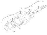
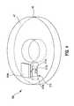
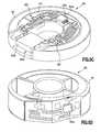
- FIG. 1depicts an exploded cut-away perspective view of an embodiment of a coaxial cable connector with a parameter sensing circuit, in accordance with the present invention
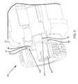
- FIG. 2depicts a close-up cut-away partial perspective view of an embodiment of a coaxial cable connector with a parameter sensing circuit, in accordance with the present invention
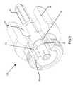
- FIG. 3depicts a cut-away perspective view of an embodiment of an assembled coaxial cable connector with an integrated parameter sensing circuit, in accordance with the present invention
- FIG. 4depicts a perspective view of an embodiment of the disk structure 40 of FIGS. 1-3 , in accordance with the present invention
- FIG. 5Adepicts a schematic block diagram view of an embodiment of a system including the power harvesting and parameter sensing circuit of FIGS. 1-4 , in accordance with the present invention
- FIG. 5Bdepicts schematic block diagram view of an embodiment of system the system of FIG. 5A including multiple sensing/processing circuits located in multiple coaxial cable connectors, in accordance with the present invention
- FIG. 6depicts a perspective view of an embodiment of a loop coupler device, in accordance with the present invention.
- FIGS. 7A-7Cdepict schematic views of embodiments of the coupler device of FIGS. 1-6 , in accordance with the present invention.
- FIGS. 8A-8Ddepict perspective views of embodiments of the disk structure of FIGS. 1-5B , in accordance with the present invention.
- FIG. 9depicts a perspective view of an embodiment of a physical parameter status/electrical parameter reader, in accordance with the present invention.
- FIG. 10depicts a side perspective cut-away view of another embodiment of a coaxial cable connector having multiple sensors, in accordance with the present invention.
- a condition of a connector connection at a given time, or over a given time periodmay comprise a physical parameter status relative to a connected coaxial cable connector.
- a physical parameter statusis an ascertainable physical state relative to the connection of the coaxial cable connector, wherein the physical parameter status may be used to help identify whether a connector connection performs accurately.
- a condition of a signal flowing through a connector at a given time, or over a given time periodmay comprise an electrical parameter of a signal flowing through a coaxial cable connector.
- An electrical parametermay comprise, among other things, an electrical signal (RF) power level, wherein the electrical signal power level may be used for discovering, troubleshooting and eliminating interference issues in a transmission line (e.g., a transmission line used in a cellular telephone system).
- RFelectrical signal
- Embodiments of a connector 100 of the present inventionmay be considered “smart”, in that the connector 100 itself ascertains physical parameter status pertaining to the connection of the connector 100 to an RF port. Additionally, embodiments of a connector 100 of the present invention may be considered “smart”, in that the connector 100 itself: detects; measures/processes a parameter of; and harvests power from an electrical signal (e.g., an RF power level) flowing through a coaxial connector.
- an electrical signale.g., an RF power level
- FIGS. 1-3depict cut-away perspective views of an embodiment of a coaxial cable connector 100 with an internal power harvesting (and parameter sensing) circuit 30 b , in accordance with the present invention.
- the connector 100includes a connector body 50 .
- the connector body 50comprises a physical structure that houses at least a portion of any internal components of a coaxial cable connector 100 . Accordingly the connector body 50 can accommodate internal positioning of various components, such as a disk structure 40 (e.g., a spacer), an interface sleeve 60 , a spacer 70 , and/or a center conductor contact 80 that may be assembled within the connector 100 .
- the connector body 50may be conductive.
- the structure of the various component elements included in a connector 100 and the overall structure of the connector 100may operably vary.
- a governing principle behind the elemental design of all features of a coaxial connector 100is that the connector 100 should be compatible with common coaxial cable interfaces pertaining to typical coaxial cable communications devices. Accordingly, the structure related to the embodiments of coaxial cable connectors 100 depicted in the various FIGS. 1-12 is intended to be exemplary.
- a connector 100may include any operable structural design allowing the connector 100 to harvest power from a signal flowing through the connector 100 , sense a condition of a connection of the connector 100 with an interface to an RF port of a common coaxial cable communications device, and report a corresponding connection performance status to a location outside of the connector 100 . Additionally, connector 100 may include any operable structural design allowing the connector 100 to harvest power from, sense, detect, measure, and report a parameter of an electrical signal flowing through connector 100 .
- a coaxial cable connector 100has internal circuitry that may harvest power, sense/process connection conditions, store data, and/or determine monitorable variables of physical parameter status such as presence of moisture (humidity detection, as by mechanical, electrical, or chemical means), connection tightness (applied mating force existent between mated components), temperature, pressure, amperage, voltage, signal level, signal frequency, impedance, return path activity, connection location (as to where along a particular signal path a connector 100 is connected), service type, installation date, previous service call date, serial number, etc.
- a connector 100includes a parameter sensing/processing (and power harvesting) circuit 30 b .
- the parameter sensing/processing (and power harvesting) circuit 30 bincludes an embedded coupler device 515 , sensors 560 , and an integrated circuit 504 b (e.g., a semiconductor device such as, among other things, a semiconductor chip) that may include an impedance matching circuit 511 , an RF power sensing circuit 502 , a RF power harvesting/power management circuit 529 , and a sensor front end circuit 569 , an analog to digital convertor (ADC) 568 , a digital control circuit 567 , a clock and data recovery CDR circuit 572 , a transmit circuit (Tx) 570 a , and a receive circuit (Rx) 570 b as illustrated and described with respect to FIGS. 4 and 5A .
- ADCanalog to digital convertor
- Txtransmit circuit
- Rxreceive circuit
- the power harvesting (and parameter sensing) circuit 30 amay be integrated onto or within typical coaxial cable connector components.
- the parameter sensing/processing circuit 30 bmay be located on/within existing connector structures.
- a connector 100may include a component such as a disk structure 40 having a face 42 .
- the parameter sensing/processing circuit 30 bmay be positioned on and/or within the face 42 of the disk structure 40 of the connector 100 .
- the parameter sensing/processing circuit 30 bis configured to: sense an R/F signal flowing through the connector 100 ; harvest power from the R/F signal flowing through the connector 100 ; and process and report conditions (e.g., temperature, connector tightness, relative humidity, etc) associated with the connector 100 when connected to an RF port.
- conditionse.g., temperature, connector tightness, relative humidity, etc
- Power for sensing/processing circuit 30 b(e.g., the integrated circuit 504 b ) and/or other powered components of a connector 100 may be provided through retrieving energy from an R/F signal flowing through the center conductor 80 .
- tracesmay be printed on and/or within the disk structure 40 and positioned so that the traces make electrical contact with (i.e., coupled to) the center conductor contact 80 at a location 46 (see FIG. 2 ).
- Contact with the center conductor contact 80 at location 46facilitates the ability for the sensing/processing circuit 30 b to draw power from the cable signal(s) passing through the center conductor contact 80 .
- Tracesmay also be formed and positioned so as to make contact with grounding components.
- a ground pathmay extend through a location 48 between the disk structure 40 and the interface sleeve 60 , or any other operably conductive component of the connector 100 .
- a sensing/processing circuit 30 bshould be powered in a way that does not significantly disrupt or interfere with electromagnetic communications that may be exchanged through the connector 100 .
- FIG. 4depicts a perspective view of an embodiment of the disk structure 40 of FIGS. 1-3 .
- the disk structure 40includes the sensing/processing circuit 30 b .
- the sensing/processing circuit 30 bincludes an embedded coupler device 515 (including wire traces 515 a , metallic cylindrical structures 515 b extending from a bottom surface through a top surface 42 of disk structure 40 , and a wire trace 515 c connecting metallic cylindrical structures 515 b thereby forming a loop coupler structure), sensors 560 , and an integrated circuit 504 b (e.g., a semiconductor device such as, among other things, a semiconductor chip) that may include an impedance matching circuit 511 , an RF power sensing circuit 502 , a RF power harvesting/power management circuit 529 , and a sensor front end circuit 569 , an analog to digital convertor (ADC) 568 , a digital control circuit 567 , a clock and data recovery (CDR) circuit 572 ,
- embedded coupler device 515is illustrated as cylindrical structures extending from a top surface 42 through a bottom surface of disk structure 40 , note that embedded coupler device 515 may comprise any geometrical shape (e.g., circular, spherical, cubicle, etc).
- Embedded coupler device 515may include a directional coupler and/or a loop coupler that harvests power from a radio frequency (RF) signal being transmitted down a transmission line (and through connector 100 of FIGS. 1-3 ) and extracts a sample of the RF signal for detecting conditions of the connector 100 .
- the harvested powermay be used to power electronic transducers/sensors (e.g., sensors 560 in FIG.
- Disk structure 40provides a surface 42 for implementing a directional coupler.
- FIG. 4illustrates an embedded directional coupler (i.e., coupler device 515 ) mounted on/within the disk structure 40 located internal to connector 100 .
- Coupler device 515harvests energy from an RF signal on the transmission line (e.g., a coaxial cable for an R/F tower).
- Coupler device 515additionally provides a real time measurement of RF signal parameters on the transmission line (e.g., a coaxial cable).
- Disk structure 40incorporates electronic components (e.g., integrated circuit 504 b such as a signal processor) to harvest the power, condition the sensed parameter signals (i.e., sensed by coupler device 515 ), and transmit a status of the connector 100 condition over a telemetry system.
- Signals sensed by the coupler device 515may include a magnitude of a voltage for forward and reverse propagating RF waveforms present on a coaxial cable center conductor (e.g., center conductor 80 of FIGS. 1-3 ) relative to ground.
- a geometry and placement of the coupler device 515 on the disk structure 515determines a calibrated measurement of RF signal parameters such as, among other things, power and voltage standing wave ratio.
- Coupler device 515allows for a measurement of forward and reverse propagating RF signals along a transmission line thereby allowing a measurement of a voltage standing wave ratio and impedance mismatch in a cabling system of the transmission line.
- the disk structure 40(including the internal sensing/processing circuit 30 b may be implemented within systems including coaxial cables and RF connectors used in cellular telephone towers.
- the disk structure 40made include syndiotactic polystyrene.
- An electroplated metallurgymay be used (i.e., on/within the disk structure 40 ) to form the coupler device 515 and electronic interconnects (e.g., wire traces 515 a ) to the sensing/processing circuit 30 b .
- the coupler device 515may be used in any application internal to a coaxial line to harvest power from RF energy propagating along the center coaxial line.
- the coupler device 515may be used to measure directly and in real time, a calibrated sample of forward and reverse voltages of the RF energy.
- the calibrated sample of the forward and reverse voltagesmay provide key information regarding the quality of the coaxial cable and connector system.
- a propagated RF signal and key parameters(such as power, voltage standing wave ratio, intersectional cable RF power loss, refection coefficient, insertion loss, etc) may be determined.
- a coaxial transmission linesupports a transmission electron microscopy (TEM) mode electromagnetic wave.
- TEM modedescribes a property of an orthogonal magnetic and electric field for an RF signal.
- TEM modeallows for an accurate description of the electromagnetic field's frequency behavior.
- An insertion of an electrically small low coupling magnetic antennae.g., coupler device 515
- coupler device 515is used to harvest power from RF signals and measure an integrity of passing RF signals (i.e., using the electromagnetic fields' fundamental RF behavior).
- Coupler device 515may be designed at a very low coupling efficiency in order to avoid insertion loss.
- Harvested powermay be used to power an on board data acquisition structure (e.g., integrated circuit 504 b ).
- Sensed RF signal powermay be fed to an on board data acquisition structure (e.g., integrated circuit 504 b ).
- Data gathered by the integrated circuit 504 bis reported back to a data gathering device (e.g., transmitter 510 a , receiver 510 b , or combiner 545 in FIGS. 5A and 5B ) through the transmission path (i.e., a coaxial cable) or wirelessly.
- a data gathering devicee.g., transmitter 510 a , receiver 510 b , or combiner 545 in FIGS. 5A and 5B
- the transmission pathi.e., a coaxial cable
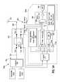
- FIG. 5Ashows schematic block diagram view of an embodiment of a system 540 b including sensing/processing circuit 30 b connected between (e.g., via a coaxial cable(s)) an antenna 523 (e.g., on a cellular telephone tower) and a transmitter 510 a and receiver 510 b (connected through a combiner 545 ).
- system 540 b of FIG. 5only illustrates one sensing/processing circuit 30 b (within a coaxial cable connector)
- system 540 bmay include multiple sensing/processing circuits 30 b (within multiple coaxial cable connectors) located at any position along a main transmission line 550 (as illustrated and described with respect to FIG. 5B ).
- Embodiments of a sensing/processing circuit 30 bmay be variably configured to include various electrical components and related circuitry so that a connector 100 can harvest power, measure, or determine connection performance by sensing a condition relative to the connection of the connector 100 , wherein knowledge of the sensed condition may be provided as physical parameter status information and used to help identify whether the connection performs accurately.
- the circuit configuration as schematically depicted in FIG. 5Ais provided to exemplify one embodiment of sensing/processing circuit 30 b that may operate with a connector 100 .
- sensing/processing circuit 30 b configurationsmay be provided to accomplish the power harvesting, sensing of physical parameters, and processing corresponding to a connector 100 connection.
- each block or portion of the sensing/processing circuit 30 bcan be individually implemented as an analog or digital circuit.
- a sensing/processing circuit 30 bmay include an embedded coupler device 515 (e.g., a directional (loop) coupler as illustrated), sensors 560 , and an integrated circuit 504 b (e.g., a semiconductor device such as, among other things, a semiconductor chip) that may include an impedance matching circuit 511 , an RF power sensing circuit 502 , a RF power harvesting/power management circuit 529 , and a sensor front end circuit 569 , an analog to digital convertor (ADC) 568 , a digital control circuit 567 , a clock and data recovery CDR circuit 572 , a transmit circuit (Tx) 570 a , and a receive circuit (Rx) 570 b .
- ADCanalog to digital convertor
- a directional couplercouples energy from main transmission line 550 to a coupled line 551 .
- the transmitter 510 a , receiver 510 b , and combiner 545are connected to the antenna 523 through coupler device 515 (i.e., the transmitter 510 a , receiver 510 b , and combiner 545 are connected to port 1 of the coupler device 515 and the antenna is connected to port 2 of the coupler device 515 ) via a coaxial cable with connectors.
- Ports 3 and 4(of the coupler device 515 ) are connected to an impedance matching circuit 511 in order to create matched terminated line impedance (i.e., optimizes a received RF signal).
- Impedance matching circuit 511is connected to RF power sensing circuit 502 and RF power harvesting/power management circuit 529 and sensor front end circuit 569 (e.g., including a multiplexer 569 a ).
- the RF power harvesting/power management circuit 529receives and conditions (e.g., regulates) the harvested power from the coupler device 515 .
- a conditioned power signale.g., a regulated voltage generated by the RF power harvesting/power management circuit 529
- the RF power sensing circuit 502receives (from the coupler device 515 ) a calibrated sample of forward and reverse voltages (i.e., from the coaxial cable).
- a propagated RF signal and key parametersmay be determined (from the forward and reverse voltages) by the RF power sensing circuit 502 .
- the sensor front end circuit 569is connected between the RF power sensing circuit 502 and the ADC 568 . Additionally, sensors 560 are connected to sensor front end circuit 569 . Although sensors 560 in FIG. 5 are illustrated as a torque sensor and a relative humidity sensor, note that are sensor may be connected to sensor front end circuit 569 for signal processing.
- sensors 560may include, among other things, a capacitive sensor structure, a temperature sensor, an optical/electric sensor, a resistance based sensor, a strain connection tightness sensor, etc.
- the sensor front end circuit 569provides protocols and drive circuitry to transmit sensor data (i.e., from coupler device 515 and/or sensors 560 after processing by ADC 568 , digital control circuit 567 , and CDR 572 ) back to the coaxial line for transmission to a data retrieval system (e.g., receiver 510 b ).
- the receiver 510 bmay include signal reader circuitry for reading and analyzing a propagated RF signal flowing through main transmission line 550 .
- SCIChas been optimized to sense the status of a coaxial cable connector system, extract power from the coaxial cable system, and report the status of the cable system by providing data transfer between the center conductor of the coaxial line in a transmission and reception mode.
- System 540 a of FIG. 5Aincorporates the integrated circuit 504 b with the sensors 560 for detecting connector failure mechanisms.
- a telemetry technologyreports the connector integrity with a unique identification for each connector to a central dispatch location (e.g., receiver 510 b ).
- a degrading quality in a connectormay be detected and corrected before a catastrophic failure occurs.
- Integrated circuit 504 bis integrated with disk 40 (of FIGS. 1-4 ) comprising interconnect metallurgy to sensors 560 and coupler device 515 .
- Integrated circuit 504 bcomprises an architecture to sense connector tightness, connector moisture, harvest RF power for powering the integrated circuit 504 b (and any additional components on the disk), monitor a quality of an RF signal on the coaxial cable, measure inside cable temperature, enable unique SC identification, provide a telemetry system for communicating the system 540 b status, etc.
- Integrated circuit 504 bis packaged to tolerate EMI events common in coaxial cable environments such as, among other things, lightning or ground potential shifts, normal operating RF power on the coaxial system (e.g., 20 watts of RF power), etc.
- An example embodiment of the integrated circuit 504 bmay enable and/or include the following eight subsystems:
- Integrated circuit 504 buses electrostatic proximity detection to measure coaxial cable connector mating tightness.
- a grounded metallic ring in a female body of the (connector)moves toward a sensing ring on the disk 40 surface thereby changing an effective capacitance.
- a two electrode capacitance structuree.g., a Wheatstone capacitance bridge
- a 20 KHz 3 VPP sinusoidal signalmay be used to stimulate the bridge.
- a differential amplifiersenses the error voltage developed on interior nodes of the bridge and converts the error voltage to a dc voltage related to connector tightness.
- Integrated circuit 504 benables relative humidity (RH) sensing based on a four resistor Wheatstone bridge.
- the RH sensing resistormay be fabricated adjacent to integrated circuit 504 b using an inter-digitated metallic finger array coated with a (nafion hydrophilic) film. Under the influence of water vapor at a surface of the film, the film conductivity varies with relative humidity and induces a change in inter-electrode resistance with respect to relative humidity. An offset voltage is proportional to the resistance bridge imbalance and therefore the relative humidity is amplified by a differential amplifier.
- Integrated circuit 504 benables temperature sensing to allow for temperature compensation of transducing elements and to monitor a temperature environment of a coaxial cable connector body.
- Integrated circuit 504 benables a fixed bias current to develop a forward bias voltage across a p-n junction.
- the p-n junction voltageexhibits fractional temperature coefficient of approximately ⁇ 2 mV/° C.
- Integrated circuit 504 benables a measurement of instantaneous RF power at each coaxial cable connector to monitor the coaxial cable connector and coaxial cable viability and to identify specific fault locations.
- Coupler device 515measures instantaneous RF power at each coaxial cable connector (i.e., propagating in a forward or reverse direction) and is connected to the integrated circuit 504 b for signal processing and conversion to a corresponding digital value. Relative voltage magnitudes of forward or reverse traveling RF waves allow for RF measurement such as, among other things, standing wave ratios, impedance mismatch, etc.
- Power (i.e., for operation) for integrated circuit 504 bis derived from power harvested from a transmission line.
- a RF signal transmitted by a master terminale.g., transmitter 510 a
- the coupled RF signalis converted to a regulated DC voltage (e.g., 3.3 vdc on-chip power supply) and provides a time base for integrated circuit 504 b clocking.
- the integrated circuit 504 bextracts less than 3 mW of power from the transmission line.
- a signals generated by transducersare conditioned into a dc voltage.
- Each sensor dc signalmay be selected by a six channel multiplexer (e.g., multiplexer 569 ) and converted to an 8-bit equivalent digital value by a dual slope integrating analog to digital converter (e.g., ADC 568 ).
- the dual slope ADCmay enable natural noise suppression by its integrating action and operates at low bias currents.
- the remote slave status(i.e., for the semiconductor device 504 b ) may be transmitted to a master terminal over a coaxial cable via the coupler device 515 .
- a data stream(for the remote slave status) may include an 8-bit parameter value for each of sensor signal, an 8 bit chip address, and an 8 bit cyclic redundancy code (CRC) for reliable communication.
- CRCcyclic redundancy code
- the integrated circuit 504 bmay be mounted on a copper substrate to act as a faraday cage to shield the integrated circuit 504 b from frequencies from 1 MHz to 3 GHz.
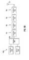
- FIG. 5Bshows schematic block diagram view of an embodiment of system 540 b of FIG. 5A including multiple sensing/processing circuits 30 b located in multiple coaxial cable connectors 100 a . . . 100 n connected between (e.g., via a coaxial cable(s)) antenna 523 (e.g., on a cellular telephone tower) and transmitter 510 a and receiver 510 b (connected through a combiner 545 ).
- Each of coaxial cable connectors 100 a . . . 100 n(comprising an associated sensing/processing circuit 30 b ) in includes an RF energy sensing/extraction point.
- the RF energymay be transmitted from an existing RF communication signal or a dedicated RF energy signal dedicated to providing power for each sensing/processing circuit 30 b.
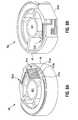
- FIG. 6depicts a perspective view of an embodiment of the coupler device 515 (e.g., a loop coupler structure) of FIGS. 1-5B .
- FIG. 6illustrates a magnetic field 605 established by an AC current through a center conductor 601 (of a coaxial cable) penetrating a suspended loop (e.g., coupler device 515 ).
- Coupler device 515includes a gap between the center conductor 601 and a substrate to avoid a sparking effect between the center conductor 601 and outer shielding that often occurs under surge conditions.
- An RF signal passing through the center conductor 601establishes an azimuthally orbiting magnetic field 605 surrounding the center conductor 601 .
- a conductive loop structure(e.g., coupler device 515 ) that supports a surface that is penetrated by the orbiting magnetic field 605 will induce a current through its windings and induce a voltage (i.e., harvested power) across its terminals dependent upon a termination impedance.
- the conductive loop structureis constructed to surround an open surface tangent to the azimuthal magnetic field 605 and induce the aforementioned current. End leads of the conductive loop structure emulate a fully connected loop while maintaining electrical separation thereby allowing for a voltage (i.e., for power electronics within the connector 100 ) to be developed across terminals (ports 3 and 4 ).
- FIGS. 7A-7Cdepict schematic views of an embodiments of the coupler device 515 (e.g., a loop coupler structure) of FIGS. 1-6 .
- a coupling structuree.g., coupler device 515
- the coupling structurewill transmit a portion of the RF power as electric and magnetic components inside the coaxial structure thereby inducing a current down the center conductor and establishing a TEM wave inside the coaxial structure.
- the coaxial linewill drive the TEM wave through the open space occupied by the coupling structure and will induce fields that will couple energy into the structures.
- FIGS. 7A-7Cdepict a TX of power from the coupling structure to a coaxial line and vice versa.
- FIG. 7Ademonstrates a TX lumped circuit model of a coaxial line.
- Model parameters including a subscript “g”indicate generator parameters.
- the generator parameterscomprise inductive and resistive Thevenin values at an output of the coupling structure to the coaxial line.
- Model parameters with a subscript “c”describe inductance, capacitance, and resistance of the coaxial line at the point of the coupling structure's placement.
- Model parameter Cpcomprises a parasitic capacitance with non-coaxial metallic structures and is on the order of pF.
- Vtxcomprises a transmission voltage that induces an electric or magnetic field component that excites the coupling structure.
- Equation 1expresses a transmission voltage in terms a generator voltage divided down by transmitter impedances.
- V TXV G Z G + Z Cc // ( Lc + Rc ) Equation ⁇ ⁇ 1
- Equation 2expresses a transmission power in terms of lumped circuit components.
- FIG. 7Bdemonstrates RF power transmitted in a TEM wave along a coaxial line's length.
- the TEM waveis received by the coupling structure and an induced power is brought through the coupling structure to internal electronics.
- a frequency dependant reception of the RF poweris dictated by the particular impedances caused by the inductive coupling between the conductive structures, the capacitive coupling with the grounded metal shielding, and the mixed coupling with the other metallic traces within the coaxial environment.
- FIG. 7Cdemonstrates an Irx current source comprising an induced dependant current that varies with the power and frequency of the transmitted signal along the coaxial line.
- the La, Ra, and Ca elementsare intrinsic and coupling impedances of the loop coupler positioned near the coaxial line.
- Cpcomprises a parasitic capacitance due to a surrounding grounded metal connector housing.
- the Lrx and Rrx elementscomprise impedances used to tune the coupling structure for optimum transmission at select frequencies.
- Vrxcomprises a received voltage to internal electronics.
- Ltsis comprises a mutual inductance created from coupling between the coupling structure and a metallic structure used to tune the coupling structure's resistive impedance at a select power transfer frequency.
- FIG. 8Adepicts a first perspective view of an embodiment of the disk structure 40 comprising the internal sensing/processing circuit 30 b of FIGS. 1-6 .
- FIG. 8Aillustrates coupler device 515 mounted to or integrated with disk structure 40 . Coupler device 515 illustrated in
- FIG. 8Bdepicts a second perspective view of an embodiment of the disk structure 40 comprising the internal sensing/processing circuit 30 b of FIGS. 1-6 .
- FIG. 8Billustrates the integrated circuit 504 b mounted to or integrated with a recesses within a side portion of the disk structure 40 .
- FIG. 8Cdepicts a perspective view of an embodiment of the disk structure 40 comprising a top mounted version of the internal sensing/processing circuit 30 b of FIGS. 1-6 .
- the sensing/processing circuit 30 b of FIG. 8Cincludes two different versions (either version may be used) of the integrated circuit 504 b : a top mounted version 505 a and a recessed mounted version 505 b .
- a combination of the top mounted version 505 a and the recessed mounted version 505 b of the integrated circuit 504 bmay be used in accordance with embodiments of the present invention.
- the disk structure 40may comprise additional electrical components 562 (e.g., transistors, resistors, capacitors, etc)
- FIG. 8Ddepicts a perspective view of an embodiment of the disk structure 40 comprising the integrated circuit 504 b mounted to or integrated with a side portion of the disk structure 40 .
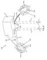
- embodiments of a coaxial cable connection system 1000may include a physical parameter status/electrical parameter reader 400 (e.g., transmitter 510 a , receiver 510 b , and/or any other signal reading device along cable 10 ) located externally to the connector 100 .
- the reader 400is configured to receive, via a signal processing circuitry (e.g., any the integrated circuit 504 b of FIG. 5A ) or embedded coupler device 515 (of FIG. 5A ), information from the power harvesting (and parameter sensing) circuit 30 a located within connector 100 or any other connectors along cable(s) 10 .
- a signal processing circuitrye.g., any the integrated circuit 504 b of FIG. 5A
- embedded coupler device 515of FIG. 5A
- a reader 400may be an output signal 2 monitoring device located somewhere along the cable line to which the connector 100 is attached.
- a physical parameter statusmay be reported through signal processing circuitry in electrical communication with the center conductor (e.g., center conductor 601 of FIG. 6 ) of the cable 10 . Then the reported status may be monitored by an individual or a computer-directed program at the cable-line head end to evaluate the reported physical parameter status and help maintain connection performance.
- the connector 100may ascertain connection conditions and may transmit physical parameter status information or an electrical parameter of an electrical signal automatically at regulated time intervals, or may transmit information when polled from a central location, such as the head end (CMTS), via a network using existing technology such as modems, taps, and cable boxes.
- CMTShead end
- a reader 400may be located on a satellite operable to transmit signals to a connector 100 .
- service technicianscould request a status report and read sensed or stored physical parameter status information (or electrical parameter information) onsite at or near a connection location, through wireless hand devices, such as a reader 400 b , or by direct terminal connections with the connector 100 , such as by a reader 400 a .
- a service techniciancould monitor connection performance via transmission over the cable line through other common coaxial communication implements such as taps, set tops, and boxes.
- Operation of a connector 100can be altered through transmitted input signals 5 from the network or by signals transmitted onsite near a connector 100 connection.
- a service technicianmay transmit a wireless input signal 4 from a reader 400 b , wherein the wireless input signal 4 includes a command operable to initiate or modify functionality of the connector 100 .
- the command of the wireless input signal 4may be a directive that triggers governing protocol of a control logic unit to execute particular logic operations that control connector 100 functionality.
- the service technicianfor instance, may utilize the reader 400 b to command the connector 100 , through a wireless input component, to presently sense a connection condition related to current moisture presence, if any, of the connection.
- the control logic unit 32may communicate with sensor, which in turn may sense a moisture condition of the connection.
- the power harvesting (and parameter sensing) circuit 30 acould then report a real-time physical parameter status related to moisture presence of the connection by dispatching an output signal 2 through an output component (e.g., the integrated circuit 504 b ) and back to the reader 400 b located outside of the connector 100 .
- the service technicianfollowing receipt of the moisture monitoring report, could then transmit another input signal 4 communicating a command for the connector 100 to sense and report physical parameter status related to moisture content twice a day at regular intervals for the next six months.
- an input signal 5 originating from the head endmay be received through an input component in electrical communication with the center conductor contact 80 to modify the earlier command from the service technician.
- the later-received input signal 5may include a command for the connector 100 to only report a physical parameter status pertaining to moisture once a day and then store the other moisture status report in memory 33 for a period of 20 days.
- a coaxial cable connector connection system 1000may include a reader 400 that is communicatively operable with devices other than a connector 100 .
- the other devicesmay have greater memory storage capacity or processor capabilities than the connector 100 and may enhance communication of physical parameter status by the connector 100 .
- a reader 400may also be configured to communicate with a coaxial communications device such as a receiving box 8 .
- the receiving box 8or other communications device, may include means for electromagnetic communication exchange with the reader 400 .
- the receiving box 8may also include means for receiving and then processing and/or storing an output signal 2 from a connector 100 , such as along a cable line.
- the communications devicesuch as a receiving box 8
- the reader-like communications devicesuch as a receiving box 8
- the reader-like communications devicecan communicate with the connector 100 via transmissions received through an input component connected to the center conductor contact 80 of the connector.
- embodiments of a reader-like device, such as a receiving box 8may then communicate information received from a connector 100 to another reader 400 .
- an output signal 2may be transmitted from a connector 100 along a cable line to a reader-like receiving box 8 to which the connector is communicatively connected.
- the reader-like receiving box 8may store physical parameter status information pertaining to the received output signal 2 .
- a usermay operate a reader 400 and communicate with the reader-like receiving box 8 sending a transmission 1002 to obtain stored physical parameter status information via a return transmission 1004 .
- a usermay operate a reader 400 to command a reader-like device, such as a receiving box 8 communicatively connected to a connector 100 , to further command the connector 100 to report a physical parameter status receivable by the reader-like receiving box 8 in the form of an output signal 2 .
- a communicatively connected connector 100may in turn provide an output signal 2 including physical parameter status information that may be forwarded by the reader-like receiving box 8 to the reader 400 via a transmission 1004 .
- the coaxial communication devicesuch as a receiving box 8 , may have an interface, such as an RF port 15 , to which the connector 100 is coupled to form a connection therewith.
- a coaxial cable connector 100is provided.
- the coaxial cable connector 100has a connector body 50 and a disk structure 40 located within the connector body 50 .
- a parameter sensing/processing (and power harvesting) circuit 30 bthat includes an embedded coupler device 515 , sensors 560 , and the integrated circuit 504 b of FIG. 5A ) is provided, wherein the parameter sensing/processing (and power harvesting) circuit 30 b is housed within the disk structure 40 .
- the parameter sensing/processing (and power harvesting) circuit 30 bhas an embedded metallic coupler device 515 configured to measure and/or harvest power from an RF signal flowing through the connector 100 when connected.
- Further physical parameter status ascertainment methodologyincludes connecting the connector 100 to an interface, such as RF port 15 , of another connection device, such as a receiving box 8 , to form a connection. Once the connection is formed, physical parameter status information applicable to the connection may be reported, via a signal processing circuit, to facilitate conveyance of the physical parameter status of the connection to a location outside of the connector body 50 .
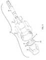
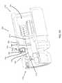
- FIG. 10depicts a side perspective cut-away view of an embodiment of a coaxial cable connector 700 having a coupler sensor 731 a (e.g., the parameter sensing/processing (and power harvesting) circuit 30 b ) and a humidity sensor 731 c .
- the connector 700includes port connection end 710 and a cable connection end 715 .
- the connector 700includes sensing circuit 730 a operable with the coupler sensor 731 a and the humidity sensor or moisture sensor 731 c .
- the coupler sensor 731 a and the humidity sensor 731 cmay be connected to a processor control logic unit 732 operable with an output transmitter 720 through leads, traces, wires, or other electrical conduits depicted as dashed lines 735 .
- the sensing circuitelectrically links the coupler sensor 731 a and the humidity sensor 731 c to the processor control logic unit 732 and the output transmitter 729 .
- the electrical conduits 735may electrically tie various components, such as a processor control logic unit 732 , sensors 731 a , 731 c and an inner conductor contact 780 together.
- the processor control logic unit 732 and the output transmitter 720may be housed within a weather-proof encasement 770 operable with a portion of the body 750 of the connector 700 .
- the encasement 770may be integral with the connector body portion 750 or may be separately joined thereto.
- the encasement 770should be designed to protect the processor control logic unit 732 and the output transmitter 720 from potentially harmful or disruptive environmental conditions.
- the coupler sensor 731 a and the humidity sensor 731 care connected via a sensing circuit 730 a to the processor control logic unit 732 and the output transmitter 720 .
- the coupler sensor 731 ais located at the port connection end 710 of the connector 700 .
- a signal level of a signal (or samples of the signal) flowing through the connector 700may be sensed by the coupler sensor 731 a.
- the humidity sensor 731 cis located within a cavity 755 of the connector 700 , wherein the cavity 755 extends from the cable connection end 715 of the connector 700 .
- the moisture sensor 731 cmay be an impedance moisture sensor configured so that the presence of water vapor or liquid water that is in contact with the sensor 731 c hinders a time-varying electric current flowing through the humidity sensor 731 c .
- the humidity sensor 731 cis in electrical communication with the processor control logic unit 732 , which can read how much impedance is existent in the electrical communication.
- the humidity sensor 731 ccan be tuned so that the contact of the sensor with water vapor or liquid water, the greater the greater the measurable impedance.
- the humidity sensor 731 cmay detect a variable range or humidity and moisture presence corresponding to an associated range of impedance thereby. Accordingly, the humidity sensor 731 c can detect the presence of humidity within the cavity 755 when a coaxial cable, such as cable 10 depicted in FIG. 9 , is connected to the cable connection end 715 of the connector 700 .
- Power for the sensing circuit 730 a , processor control unit 732 , output transmitter 720 , coupler sensor 731 a , and/or the humidity sensor 731 c of embodiments of the connector 700 depicted in FIG. 10may be provided through electrical contact with the inner conductor contact 780 (using the aforementioned power harvesting process).
- the electrical conduits 735 connected to the inner conductor contact 780may facilitate the ability for various connector 700 components to draw power from the cable signal(s) passing through the inner connector contact 780 .
- electrical conduits 735may be formed and positioned so as to make contact with grounding components of the connector 700 .
Landscapes
- Engineering & Computer Science (AREA)
- Microelectronics & Electronic Packaging (AREA)
- Arrangements For Transmission Of Measured Signals (AREA)
Abstract
Description
Claims (25)
Priority Applications (1)
| Application Number | Priority Date | Filing Date | Title |
|---|---|---|---|
| US12/961,555US8414326B2 (en) | 2008-11-17 | 2010-12-07 | Internal coaxial cable connector integrated circuit and method of use thereof |
Applications Claiming Priority (2)
| Application Number | Priority Date | Filing Date | Title |
|---|---|---|---|
| US12/271,999US7850482B2 (en) | 2008-11-17 | 2008-11-17 | Coaxial connector with integrated mating force sensor and method of use thereof |
| US12/961,555US8414326B2 (en) | 2008-11-17 | 2010-12-07 | Internal coaxial cable connector integrated circuit and method of use thereof |
Related Parent Applications (1)
| Application Number | Title | Priority Date | Filing Date |
|---|---|---|---|
| US12/271,999Continuation-In-PartUS7850482B2 (en) | 2008-11-17 | 2008-11-17 | Coaxial connector with integrated mating force sensor and method of use thereof |
Publications (2)
| Publication Number | Publication Date |
|---|---|
| US20110077884A1 US20110077884A1 (en) | 2011-03-31 |
| US8414326B2true US8414326B2 (en) | 2013-04-09 |
Family
ID=43781254
Family Applications (1)
| Application Number | Title | Priority Date | Filing Date |
|---|---|---|---|
| US12/961,555Expired - Fee RelatedUS8414326B2 (en) | 2008-11-17 | 2010-12-07 | Internal coaxial cable connector integrated circuit and method of use thereof |
Country Status (1)
| Country | Link |
|---|---|
| US (1) | US8414326B2 (en) |
Cited By (169)
| Publication number | Priority date | Publication date | Assignee | Title |
|---|---|---|---|---|
| US20110237125A1 (en)* | 2007-09-24 | 2011-09-29 | John Mezzalingua Associates, Inc. | Status sensing and reporting interface |
| US9042812B1 (en) | 2013-11-06 | 2015-05-26 | At&T Intellectual Property I, Lp | Surface-wave communications and methods thereof |
| US9113347B2 (en) | 2012-12-05 | 2015-08-18 | At&T Intellectual Property I, Lp | Backhaul link for distributed antenna system |
| US9209902B2 (en) | 2013-12-10 | 2015-12-08 | At&T Intellectual Property I, L.P. | Quasi-optical coupler |
| US9312919B1 (en) | 2014-10-21 | 2016-04-12 | At&T Intellectual Property I, Lp | Transmission device with impairment compensation and methods for use therewith |
| US9461706B1 (en) | 2015-07-31 | 2016-10-04 | At&T Intellectual Property I, Lp | Method and apparatus for exchanging communication signals |
| US9490869B1 (en) | 2015-05-14 | 2016-11-08 | At&T Intellectual Property I, L.P. | Transmission medium having multiple cores and methods for use therewith |
| US9503189B2 (en) | 2014-10-10 | 2016-11-22 | At&T Intellectual Property I, L.P. | Method and apparatus for arranging communication sessions in a communication system |
| US9509415B1 (en) | 2015-06-25 | 2016-11-29 | At&T Intellectual Property I, L.P. | Methods and apparatus for inducing a fundamental wave mode on a transmission medium |
| US9520945B2 (en) | 2014-10-21 | 2016-12-13 | At&T Intellectual Property I, L.P. | Apparatus for providing communication services and methods thereof |
| US9525210B2 (en) | 2014-10-21 | 2016-12-20 | At&T Intellectual Property I, L.P. | Guided-wave transmission device with non-fundamental mode propagation and methods for use therewith |
| US9525524B2 (en) | 2013-05-31 | 2016-12-20 | At&T Intellectual Property I, L.P. | Remote distributed antenna system |
| US9531427B2 (en) | 2014-11-20 | 2016-12-27 | At&T Intellectual Property I, L.P. | Transmission device with mode division multiplexing and methods for use therewith |
| US9564947B2 (en) | 2014-10-21 | 2017-02-07 | At&T Intellectual Property I, L.P. | Guided-wave transmission device with diversity and methods for use therewith |
| US9577307B2 (en) | 2014-10-21 | 2017-02-21 | At&T Intellectual Property I, L.P. | Guided-wave transmission device and methods for use therewith |
| US9608740B2 (en) | 2015-07-15 | 2017-03-28 | At&T Intellectual Property I, L.P. | Method and apparatus for launching a wave mode that mitigates interference |
| US9608692B2 (en) | 2015-06-11 | 2017-03-28 | At&T Intellectual Property I, L.P. | Repeater and methods for use therewith |
| US9615269B2 (en) | 2014-10-02 | 2017-04-04 | At&T Intellectual Property I, L.P. | Method and apparatus that provides fault tolerance in a communication network |
| US9628116B2 (en) | 2015-07-14 | 2017-04-18 | At&T Intellectual Property I, L.P. | Apparatus and methods for transmitting wireless signals |
| US9628854B2 (en) | 2014-09-29 | 2017-04-18 | At&T Intellectual Property I, L.P. | Method and apparatus for distributing content in a communication network |
| US9640850B2 (en) | 2015-06-25 | 2017-05-02 | At&T Intellectual Property I, L.P. | Methods and apparatus for inducing a non-fundamental wave mode on a transmission medium |
| US9654173B2 (en) | 2014-11-20 | 2017-05-16 | At&T Intellectual Property I, L.P. | Apparatus for powering a communication device and methods thereof |
| US9653770B2 (en) | 2014-10-21 | 2017-05-16 | At&T Intellectual Property I, L.P. | Guided wave coupler, coupling module and methods for use therewith |
| US9667317B2 (en) | 2015-06-15 | 2017-05-30 | At&T Intellectual Property I, L.P. | Method and apparatus for providing security using network traffic adjustments |
| US9680670B2 (en) | 2014-11-20 | 2017-06-13 | At&T Intellectual Property I, L.P. | Transmission device with channel equalization and control and methods for use therewith |
| US9685992B2 (en) | 2014-10-03 | 2017-06-20 | At&T Intellectual Property I, L.P. | Circuit panel network and methods thereof |
| US9692101B2 (en) | 2014-08-26 | 2017-06-27 | At&T Intellectual Property I, L.P. | Guided wave couplers for coupling electromagnetic waves between a waveguide surface and a surface of a wire |
| US9705571B2 (en) | 2015-09-16 | 2017-07-11 | At&T Intellectual Property I, L.P. | Method and apparatus for use with a radio distributed antenna system |
| US9705561B2 (en) | 2015-04-24 | 2017-07-11 | At&T Intellectual Property I, L.P. | Directional coupling device and methods for use therewith |
| US9722318B2 (en) | 2015-07-14 | 2017-08-01 | At&T Intellectual Property I, L.P. | Method and apparatus for coupling an antenna to a device |
| US9729197B2 (en) | 2015-10-01 | 2017-08-08 | At&T Intellectual Property I, L.P. | Method and apparatus for communicating network management traffic over a network |
| US9735833B2 (en) | 2015-07-31 | 2017-08-15 | At&T Intellectual Property I, L.P. | Method and apparatus for communications management in a neighborhood network |
| US9742462B2 (en) | 2014-12-04 | 2017-08-22 | At&T Intellectual Property I, L.P. | Transmission medium and communication interfaces and methods for use therewith |
| US9749013B2 (en) | 2015-03-17 | 2017-08-29 | At&T Intellectual Property I, L.P. | Method and apparatus for reducing attenuation of electromagnetic waves guided by a transmission medium |
| US9748626B2 (en) | 2015-05-14 | 2017-08-29 | At&T Intellectual Property I, L.P. | Plurality of cables having different cross-sectional shapes which are bundled together to form a transmission medium |
| US9749053B2 (en) | 2015-07-23 | 2017-08-29 | At&T Intellectual Property I, L.P. | Node device, repeater and methods for use therewith |
| US9755697B2 (en) | 2014-09-15 | 2017-09-05 | At&T Intellectual Property I, L.P. | Method and apparatus for sensing a condition in a transmission medium of electromagnetic waves |
| US9762289B2 (en) | 2014-10-14 | 2017-09-12 | At&T Intellectual Property I, L.P. | Method and apparatus for transmitting or receiving signals in a transportation system |
| US9769020B2 (en) | 2014-10-21 | 2017-09-19 | At&T Intellectual Property I, L.P. | Method and apparatus for responding to events affecting communications in a communication network |
| US9769128B2 (en) | 2015-09-28 | 2017-09-19 | At&T Intellectual Property I, L.P. | Method and apparatus for encryption of communications over a network |
| US9780834B2 (en) | 2014-10-21 | 2017-10-03 | At&T Intellectual Property I, L.P. | Method and apparatus for transmitting electromagnetic waves |
| US9793951B2 (en) | 2015-07-15 | 2017-10-17 | At&T Intellectual Property I, L.P. | Method and apparatus for launching a wave mode that mitigates interference |
| US9793955B2 (en) | 2015-04-24 | 2017-10-17 | At&T Intellectual Property I, Lp | Passive electrical coupling device and methods for use therewith |
| US9793954B2 (en) | 2015-04-28 | 2017-10-17 | At&T Intellectual Property I, L.P. | Magnetic coupling device and methods for use therewith |
| US9800327B2 (en) | 2014-11-20 | 2017-10-24 | At&T Intellectual Property I, L.P. | Apparatus for controlling operations of a communication device and methods thereof |
| US9820146B2 (en) | 2015-06-12 | 2017-11-14 | At&T Intellectual Property I, L.P. | Method and apparatus for authentication and identity management of communicating devices |
| US9838896B1 (en) | 2016-12-09 | 2017-12-05 | At&T Intellectual Property I, L.P. | Method and apparatus for assessing network coverage |
| US9836957B2 (en) | 2015-07-14 | 2017-12-05 | At&T Intellectual Property I, L.P. | Method and apparatus for communicating with premises equipment |
| US9847850B2 (en) | 2014-10-14 | 2017-12-19 | At&T Intellectual Property I, L.P. | Method and apparatus for adjusting a mode of communication in a communication network |
| US9847566B2 (en) | 2015-07-14 | 2017-12-19 | At&T Intellectual Property I, L.P. | Method and apparatus for adjusting a field of a signal to mitigate interference |
| US9853342B2 (en) | 2015-07-14 | 2017-12-26 | At&T Intellectual Property I, L.P. | Dielectric transmission medium connector and methods for use therewith |
| US9860075B1 (en) | 2016-08-26 | 2018-01-02 | At&T Intellectual Property I, L.P. | Method and communication node for broadband distribution |
| US9865911B2 (en) | 2015-06-25 | 2018-01-09 | At&T Intellectual Property I, L.P. | Waveguide system for slot radiating first electromagnetic waves that are combined into a non-fundamental wave mode second electromagnetic wave on a transmission medium |
| US9866309B2 (en) | 2015-06-03 | 2018-01-09 | At&T Intellectual Property I, Lp | Host node device and methods for use therewith |
| US9871283B2 (en) | 2015-07-23 | 2018-01-16 | At&T Intellectual Property I, Lp | Transmission medium having a dielectric core comprised of plural members connected by a ball and socket configuration |
| US9871282B2 (en) | 2015-05-14 | 2018-01-16 | At&T Intellectual Property I, L.P. | At least one transmission medium having a dielectric surface that is covered at least in part by a second dielectric |
| US9876571B2 (en) | 2015-02-20 | 2018-01-23 | At&T Intellectual Property I, Lp | Guided-wave transmission device with non-fundamental mode propagation and methods for use therewith |
| US9876264B2 (en) | 2015-10-02 | 2018-01-23 | At&T Intellectual Property I, Lp | Communication system, guided wave switch and methods for use therewith |
| US9876605B1 (en) | 2016-10-21 | 2018-01-23 | At&T Intellectual Property I, L.P. | Launcher and coupling system to support desired guided wave mode |
| US9882257B2 (en) | 2015-07-14 | 2018-01-30 | At&T Intellectual Property I, L.P. | Method and apparatus for launching a wave mode that mitigates interference |
| US9882277B2 (en) | 2015-10-02 | 2018-01-30 | At&T Intellectual Property I, Lp | Communication device and antenna assembly with actuated gimbal mount |
| US9893795B1 (en) | 2016-12-07 | 2018-02-13 | At&T Intellectual Property I, Lp | Method and repeater for broadband distribution |
| US9906269B2 (en) | 2014-09-17 | 2018-02-27 | At&T Intellectual Property I, L.P. | Monitoring and mitigating conditions in a communication network |
| US9904535B2 (en) | 2015-09-14 | 2018-02-27 | At&T Intellectual Property I, L.P. | Method and apparatus for distributing software |
| US9912382B2 (en) | 2015-06-03 | 2018-03-06 | At&T Intellectual Property I, Lp | Network termination and methods for use therewith |
| US9913139B2 (en) | 2015-06-09 | 2018-03-06 | At&T Intellectual Property I, L.P. | Signal fingerprinting for authentication of communicating devices |
| US9912027B2 (en) | 2015-07-23 | 2018-03-06 | At&T Intellectual Property I, L.P. | Method and apparatus for exchanging communication signals |
| US9911020B1 (en) | 2016-12-08 | 2018-03-06 | At&T Intellectual Property I, L.P. | Method and apparatus for tracking via a radio frequency identification device |
| US9912419B1 (en) | 2016-08-24 | 2018-03-06 | At&T Intellectual Property I, L.P. | Method and apparatus for managing a fault in a distributed antenna system |
| US9917341B2 (en) | 2015-05-27 | 2018-03-13 | At&T Intellectual Property I, L.P. | Apparatus and method for launching electromagnetic waves and for modifying radial dimensions of the propagating electromagnetic waves |
| US9927517B1 (en) | 2016-12-06 | 2018-03-27 | At&T Intellectual Property I, L.P. | Apparatus and methods for sensing rainfall |
| US9948354B2 (en) | 2015-04-28 | 2018-04-17 | At&T Intellectual Property I, L.P. | Magnetic coupling device with reflective plate and methods for use therewith |
| US9948333B2 (en) | 2015-07-23 | 2018-04-17 | At&T Intellectual Property I, L.P. | Method and apparatus for wireless communications to mitigate interference |
| US9954287B2 (en) | 2014-11-20 | 2018-04-24 | At&T Intellectual Property I, L.P. | Apparatus for converting wireless signals and electromagnetic waves and methods thereof |
| US9967173B2 (en) | 2015-07-31 | 2018-05-08 | At&T Intellectual Property I, L.P. | Method and apparatus for authentication and identity management of communicating devices |
| US9973940B1 (en) | 2017-02-27 | 2018-05-15 | At&T Intellectual Property I, L.P. | Apparatus and methods for dynamic impedance matching of a guided wave launcher |
| US9991580B2 (en) | 2016-10-21 | 2018-06-05 | At&T Intellectual Property I, L.P. | Launcher and coupling system for guided wave mode cancellation |
| US9997819B2 (en) | 2015-06-09 | 2018-06-12 | At&T Intellectual Property I, L.P. | Transmission medium and method for facilitating propagation of electromagnetic waves via a core |
| US9998870B1 (en) | 2016-12-08 | 2018-06-12 | At&T Intellectual Property I, L.P. | Method and apparatus for proximity sensing |
| US9999038B2 (en) | 2013-05-31 | 2018-06-12 | At&T Intellectual Property I, L.P. | Remote distributed antenna system |
| US10009901B2 (en) | 2015-09-16 | 2018-06-26 | At&T Intellectual Property I, L.P. | Method, apparatus, and computer-readable storage medium for managing utilization of wireless resources between base stations |
| US10009065B2 (en) | 2012-12-05 | 2018-06-26 | At&T Intellectual Property I, L.P. | Backhaul link for distributed antenna system |
| US10009063B2 (en) | 2015-09-16 | 2018-06-26 | At&T Intellectual Property I, L.P. | Method and apparatus for use with a radio distributed antenna system having an out-of-band reference signal |
| US10009067B2 (en) | 2014-12-04 | 2018-06-26 | At&T Intellectual Property I, L.P. | Method and apparatus for configuring a communication interface |
| US10020587B2 (en) | 2015-07-31 | 2018-07-10 | At&T Intellectual Property I, L.P. | Radial antenna and methods for use therewith |
| US10020844B2 (en) | 2016-12-06 | 2018-07-10 | T&T Intellectual Property I, L.P. | Method and apparatus for broadcast communication via guided waves |
| US10027397B2 (en) | 2016-12-07 | 2018-07-17 | At&T Intellectual Property I, L.P. | Distributed antenna system and methods for use therewith |
| US10033108B2 (en) | 2015-07-14 | 2018-07-24 | At&T Intellectual Property I, L.P. | Apparatus and methods for generating an electromagnetic wave having a wave mode that mitigates interference |
| US10033107B2 (en) | 2015-07-14 | 2018-07-24 | At&T Intellectual Property I, L.P. | Method and apparatus for coupling an antenna to a device |
| US10044409B2 (en) | 2015-07-14 | 2018-08-07 | At&T Intellectual Property I, L.P. | Transmission medium and methods for use therewith |
| US10051483B2 (en) | 2015-10-16 | 2018-08-14 | At&T Intellectual Property I, L.P. | Method and apparatus for directing wireless signals |
| US10051629B2 (en) | 2015-09-16 | 2018-08-14 | At&T Intellectual Property I, L.P. | Method and apparatus for use with a radio distributed antenna system having an in-band reference signal |
| US10069535B2 (en) | 2016-12-08 | 2018-09-04 | At&T Intellectual Property I, L.P. | Apparatus and methods for launching electromagnetic waves having a certain electric field structure |
| US10074890B2 (en) | 2015-10-02 | 2018-09-11 | At&T Intellectual Property I, L.P. | Communication device and antenna with integrated light assembly |
| US10079661B2 (en) | 2015-09-16 | 2018-09-18 | At&T Intellectual Property I, L.P. | Method and apparatus for use with a radio distributed antenna system having a clock reference |
| US10090606B2 (en) | 2015-07-15 | 2018-10-02 | At&T Intellectual Property I, L.P. | Antenna system with dielectric array and methods for use therewith |
| US10090594B2 (en) | 2016-11-23 | 2018-10-02 | At&T Intellectual Property I, L.P. | Antenna system having structural configurations for assembly |
| US10103801B2 (en) | 2015-06-03 | 2018-10-16 | At&T Intellectual Property I, L.P. | Host node device and methods for use therewith |
| US10103422B2 (en) | 2016-12-08 | 2018-10-16 | At&T Intellectual Property I, L.P. | Method and apparatus for mounting network devices |
| US10135147B2 (en) | 2016-10-18 | 2018-11-20 | At&T Intellectual Property I, L.P. | Apparatus and methods for launching guided waves via an antenna |
| US10136434B2 (en) | 2015-09-16 | 2018-11-20 | At&T Intellectual Property I, L.P. | Method and apparatus for use with a radio distributed antenna system having an ultra-wideband control channel |
| US10135145B2 (en) | 2016-12-06 | 2018-11-20 | At&T Intellectual Property I, L.P. | Apparatus and methods for generating an electromagnetic wave along a transmission medium |
| US10135146B2 (en) | 2016-10-18 | 2018-11-20 | At&T Intellectual Property I, L.P. | Apparatus and methods for launching guided waves via circuits |
| US10139820B2 (en) | 2016-12-07 | 2018-11-27 | At&T Intellectual Property I, L.P. | Method and apparatus for deploying equipment of a communication system |
| US10142086B2 (en) | 2015-06-11 | 2018-11-27 | At&T Intellectual Property I, L.P. | Repeater and methods for use therewith |
| US10148016B2 (en) | 2015-07-14 | 2018-12-04 | At&T Intellectual Property I, L.P. | Apparatus and methods for communicating utilizing an antenna array |
| US10144036B2 (en) | 2015-01-30 | 2018-12-04 | At&T Intellectual Property I, L.P. | Method and apparatus for mitigating interference affecting a propagation of electromagnetic waves guided by a transmission medium |
| US10154493B2 (en) | 2015-06-03 | 2018-12-11 | At&T Intellectual Property I, L.P. | Network termination and methods for use therewith |
| EP3283892A4 (en)* | 2015-04-15 | 2018-12-26 | Cooper Technologies Company | Systems, methods, and devices for diagnosing integrity of electrical conductor-carrying systems |
| US10170840B2 (en) | 2015-07-14 | 2019-01-01 | At&T Intellectual Property I, L.P. | Apparatus and methods for sending or receiving electromagnetic signals |
| US10168695B2 (en) | 2016-12-07 | 2019-01-01 | At&T Intellectual Property I, L.P. | Method and apparatus for controlling an unmanned aircraft |
| US10178445B2 (en) | 2016-11-23 | 2019-01-08 | At&T Intellectual Property I, L.P. | Methods, devices, and systems for load balancing between a plurality of waveguides |
| US10205655B2 (en) | 2015-07-14 | 2019-02-12 | At&T Intellectual Property I, L.P. | Apparatus and methods for communicating utilizing an antenna array and multiple communication paths |
| US10224634B2 (en) | 2016-11-03 | 2019-03-05 | At&T Intellectual Property I, L.P. | Methods and apparatus for adjusting an operational characteristic of an antenna |
| US10225025B2 (en) | 2016-11-03 | 2019-03-05 | At&T Intellectual Property I, L.P. | Method and apparatus for detecting a fault in a communication system |
| US10243270B2 (en) | 2016-12-07 | 2019-03-26 | At&T Intellectual Property I, L.P. | Beam adaptive multi-feed dielectric antenna system and methods for use therewith |
| US10243784B2 (en) | 2014-11-20 | 2019-03-26 | At&T Intellectual Property I, L.P. | System for generating topology information and methods thereof |
| US10264586B2 (en) | 2016-12-09 | 2019-04-16 | At&T Mobility Ii Llc | Cloud-based packet controller and methods for use therewith |
| US10268848B2 (en) | 2017-05-19 | 2019-04-23 | International Business Machines Corporation | Apparatus to detect cable seating or disturbance |
| US10291311B2 (en) | 2016-09-09 | 2019-05-14 | At&T Intellectual Property I, L.P. | Method and apparatus for mitigating a fault in a distributed antenna system |
| US10291334B2 (en) | 2016-11-03 | 2019-05-14 | At&T Intellectual Property I, L.P. | System for detecting a fault in a communication system |
| US10298293B2 (en) | 2017-03-13 | 2019-05-21 | At&T Intellectual Property I, L.P. | Apparatus of communication utilizing wireless network devices |
| US10305190B2 (en) | 2016-12-01 | 2019-05-28 | At&T Intellectual Property I, L.P. | Reflecting dielectric antenna system and methods for use therewith |
| US10312567B2 (en) | 2016-10-26 | 2019-06-04 | At&T Intellectual Property I, L.P. | Launcher with planar strip antenna and methods for use therewith |
| US10320586B2 (en) | 2015-07-14 | 2019-06-11 | At&T Intellectual Property I, L.P. | Apparatus and methods for generating non-interfering electromagnetic waves on an insulated transmission medium |
| US10326689B2 (en) | 2016-12-08 | 2019-06-18 | At&T Intellectual Property I, L.P. | Method and system for providing alternative communication paths |
| US10326494B2 (en) | 2016-12-06 | 2019-06-18 | At&T Intellectual Property I, L.P. | Apparatus for measurement de-embedding and methods for use therewith |
| US10340601B2 (en) | 2016-11-23 | 2019-07-02 | At&T Intellectual Property I, L.P. | Multi-antenna system and methods for use therewith |
| US10340573B2 (en) | 2016-10-26 | 2019-07-02 | At&T Intellectual Property I, L.P. | Launcher with cylindrical coupling device and methods for use therewith |
| US10340600B2 (en) | 2016-10-18 | 2019-07-02 | At&T Intellectual Property I, L.P. | Apparatus and methods for launching guided waves via plural waveguide systems |
| US10341142B2 (en) | 2015-07-14 | 2019-07-02 | At&T Intellectual Property I, L.P. | Apparatus and methods for generating non-interfering electromagnetic waves on an uninsulated conductor |
| US10340603B2 (en) | 2016-11-23 | 2019-07-02 | At&T Intellectual Property I, L.P. | Antenna system having shielded structural configurations for assembly |
| US10340983B2 (en) | 2016-12-09 | 2019-07-02 | At&T Intellectual Property I, L.P. | Method and apparatus for surveying remote sites via guided wave communications |
| US10348391B2 (en) | 2015-06-03 | 2019-07-09 | At&T Intellectual Property I, L.P. | Client node device with frequency conversion and methods for use therewith |
| US10355367B2 (en) | 2015-10-16 | 2019-07-16 | At&T Intellectual Property I, L.P. | Antenna structure for exchanging wireless signals |
| US10361489B2 (en) | 2016-12-01 | 2019-07-23 | At&T Intellectual Property I, L.P. | Dielectric dish antenna system and methods for use therewith |
| US10359749B2 (en) | 2016-12-07 | 2019-07-23 | At&T Intellectual Property I, L.P. | Method and apparatus for utilities management via guided wave communication |
| US10374316B2 (en) | 2016-10-21 | 2019-08-06 | At&T Intellectual Property I, L.P. | System and dielectric antenna with non-uniform dielectric |
| US10382976B2 (en) | 2016-12-06 | 2019-08-13 | At&T Intellectual Property I, L.P. | Method and apparatus for managing wireless communications based on communication paths and network device positions |
| US10389037B2 (en) | 2016-12-08 | 2019-08-20 | At&T Intellectual Property I, L.P. | Apparatus and methods for selecting sections of an antenna array and use therewith |
| US10389029B2 (en) | 2016-12-07 | 2019-08-20 | At&T Intellectual Property I, L.P. | Multi-feed dielectric antenna system with core selection and methods for use therewith |
| US10396887B2 (en) | 2015-06-03 | 2019-08-27 | At&T Intellectual Property I, L.P. | Client node device and methods for use therewith |
| US10411356B2 (en) | 2016-12-08 | 2019-09-10 | At&T Intellectual Property I, L.P. | Apparatus and methods for selectively targeting communication devices with an antenna array |
| US10439675B2 (en) | 2016-12-06 | 2019-10-08 | At&T Intellectual Property I, L.P. | Method and apparatus for repeating guided wave communication signals |
| US10446936B2 (en) | 2016-12-07 | 2019-10-15 | At&T Intellectual Property I, L.P. | Multi-feed dielectric antenna system and methods for use therewith |
| US10498044B2 (en) | 2016-11-03 | 2019-12-03 | At&T Intellectual Property I, L.P. | Apparatus for configuring a surface of an antenna |
| US10530505B2 (en) | 2016-12-08 | 2020-01-07 | At&T Intellectual Property I, L.P. | Apparatus and methods for launching electromagnetic waves along a transmission medium |
| US10535928B2 (en) | 2016-11-23 | 2020-01-14 | At&T Intellectual Property I, L.P. | Antenna system and methods for use therewith |
| US10547348B2 (en) | 2016-12-07 | 2020-01-28 | At&T Intellectual Property I, L.P. | Method and apparatus for switching transmission mediums in a communication system |
| US10601494B2 (en) | 2016-12-08 | 2020-03-24 | At&T Intellectual Property I, L.P. | Dual-band communication device and method for use therewith |
| US10637149B2 (en) | 2016-12-06 | 2020-04-28 | At&T Intellectual Property I, L.P. | Injection molded dielectric antenna and methods for use therewith |
| US10650940B2 (en) | 2015-05-15 | 2020-05-12 | At&T Intellectual Property I, L.P. | Transmission medium having a conductive material and methods for use therewith |
| US10665942B2 (en) | 2015-10-16 | 2020-05-26 | At&T Intellectual Property I, L.P. | Method and apparatus for adjusting wireless communications |
| US10679767B2 (en) | 2015-05-15 | 2020-06-09 | At&T Intellectual Property I, L.P. | Transmission medium having a conductive material and methods for use therewith |
| US10694379B2 (en) | 2016-12-06 | 2020-06-23 | At&T Intellectual Property I, L.P. | Waveguide system with device-based authentication and methods for use therewith |
| US20200203896A1 (en)* | 2018-12-20 | 2020-06-25 | Abb Schweiz Ag | Power cable connector, electrical system and method for assembling power cable connector |
| US10727599B2 (en) | 2016-12-06 | 2020-07-28 | At&T Intellectual Property I, L.P. | Launcher with slot antenna and methods for use therewith |
| US20200251870A1 (en)* | 2019-01-31 | 2020-08-06 | Tyco Electronics (Shanghai) Co. Ltd. | Detection Device And Method For Detecting Insertion Depth Of Terminal Of Cable Connector |
| US10755542B2 (en) | 2016-12-06 | 2020-08-25 | At&T Intellectual Property I, L.P. | Method and apparatus for surveillance via guided wave communication |
| US10777873B2 (en) | 2016-12-08 | 2020-09-15 | At&T Intellectual Property I, L.P. | Method and apparatus for mounting network devices |
| US10784670B2 (en) | 2015-07-23 | 2020-09-22 | At&T Intellectual Property I, L.P. | Antenna support for aligning an antenna |
| US10811767B2 (en) | 2016-10-21 | 2020-10-20 | At&T Intellectual Property I, L.P. | System and dielectric antenna with convex dielectric radome |
| US10819035B2 (en) | 2016-12-06 | 2020-10-27 | At&T Intellectual Property I, L.P. | Launcher with helical antenna and methods for use therewith |
| US10916969B2 (en) | 2016-12-08 | 2021-02-09 | At&T Intellectual Property I, L.P. | Method and apparatus for providing power using an inductive coupling |
| US10938108B2 (en) | 2016-12-08 | 2021-03-02 | At&T Intellectual Property I, L.P. | Frequency selective multi-feed dielectric antenna system and methods for use therewith |
| US20210119381A1 (en)* | 2018-04-17 | 2021-04-22 | John Mezzalingua Associates, LLC | Annular abutment/alignment guide for cable connectors |
| US11032819B2 (en) | 2016-09-15 | 2021-06-08 | At&T Intellectual Property I, L.P. | Method and apparatus for use with a radio distributed antenna system having a control channel reference signal |
| US20220174613A1 (en)* | 2019-08-16 | 2022-06-02 | Huawei Technologies Co., Ltd. | Signal sending method and apparatus, and signal receiving method and apparatus |
| TWI798072B (en)* | 2022-04-27 | 2023-04-01 | 宣德科技股份有限公司 | Connector, manufacturing method thereof and connector assembly |
Families Citing this family (7)
| Publication number | Priority date | Publication date | Assignee | Title |
|---|---|---|---|---|
| US8303334B2 (en)* | 2008-11-17 | 2012-11-06 | John Mezzalingua Associates, Inc. | Embedded coupler device and method of use thereof |
| US8419464B2 (en) | 2008-11-17 | 2013-04-16 | Ppc Broadband, Inc. | Coaxial connector with integrated molded substrate and method of use thereof |
| US8376774B2 (en) | 2008-11-17 | 2013-02-19 | Rochester Institute Of Technology | Power extracting device and method of use thereof |
| CN107656720B (en)* | 2017-09-30 | 2020-06-30 | 四川长虹电器股份有限公司 | Circuit for automatically identifying coaxial audio line access |
| EP3608679B1 (en) | 2018-08-08 | 2023-03-01 | Rohde & Schwarz GmbH & Co. KG | Rf cable and cable-bound path loss determination method |
| WO2020093397A1 (en)* | 2018-11-09 | 2020-05-14 | Abb Schweiz Ag | Basic insulating plug and electric system |
| DE102020111868A1 (en)* | 2020-04-30 | 2021-11-04 | Eto Magnetic Gmbh | Electrical connection device, transceiver system and method of operating the electrical connection device |
Citations (110)
| Publication number | Priority date | Publication date | Assignee | Title |
|---|---|---|---|---|
| US2640118A (en) | 1950-12-15 | 1953-05-26 | Edwin G Werner | Coaxial cable connector |
| US3196424A (en) | 1963-09-30 | 1965-07-20 | Thomas K C Hardesty | Cable connector with monitored locking feature |
| US3388590A (en) | 1965-11-29 | 1968-06-18 | Hugh L. Dryden | Connector internal force gauge |
| US3396339A (en)* | 1963-11-29 | 1968-08-06 | Varian Associates | Capacitive voltage sensing device including coaxially disposed conductive tubes and electrical discharge inhibition means |
| US3524133A (en)* | 1966-09-09 | 1970-08-11 | Gen Electric | Static state voltage and current monitoring device for electric power cable terminations |
| US3657650A (en)* | 1969-09-08 | 1972-04-18 | Gen Electric | Current and voltage monitoring module for electric conductor terminations |
| US3686623A (en) | 1968-11-26 | 1972-08-22 | Bunker Ramo | Coaxial cable connector plug |
| US3768089A (en) | 1972-05-18 | 1973-10-23 | Gte Automatic Electric Lab Inc | Jack strip gage |
| US3808580A (en) | 1972-12-18 | 1974-04-30 | Matrix Science Corp | Self-locking coupling nut for electrical connectors |
| US3945704A (en) | 1974-03-28 | 1976-03-23 | Kraus Robert A | Device for detecting an applied compressive load |
| US3961330A (en) | 1973-12-21 | 1976-06-01 | Ross Alan Davis | Antenna system utilizing currents in conductive body |
| US3960428A (en) | 1975-04-07 | 1976-06-01 | International Telephone And Telegraph Corporation | Electrical connector |
| US4034289A (en)* | 1976-01-05 | 1977-07-05 | Motorola, Inc. | RF power monitor utilizing bi-directional coupler |
| US4084875A (en) | 1975-01-10 | 1978-04-18 | International Telephone And Telegraph Corporation | Electrical connector |
| US4240445A (en) | 1978-10-23 | 1980-12-23 | University Of Utah | Electromagnetic energy coupler/receiver apparatus and method |
| US4421377A (en) | 1980-09-25 | 1983-12-20 | Georg Spinner | Connector for HF coaxial cable |
| US4489419A (en) | 1981-10-29 | 1984-12-18 | An Wang | Data communication system |
| US4758459A (en) | 1987-01-28 | 1988-07-19 | Northern Telecom Limited | Molded circuit board |
| US4777381A (en)* | 1983-04-13 | 1988-10-11 | Fernandes Roosevelt A | Electrical power line and substation monitoring apparatus and systems |
| US4898759A (en) | 1988-07-27 | 1990-02-06 | Nidec Corporation | Molded printed circuit board for use with a brushless electric motor |
| US4911655A (en) | 1988-09-19 | 1990-03-27 | Raychem Corporation | Wire connect and disconnect indicator |
| US4915639A (en) | 1988-11-08 | 1990-04-10 | B.A.S.E.C. Industries, Ltd. | "Smart" AC receptacle and complementary plug |
| US4927382A (en) | 1987-11-03 | 1990-05-22 | Siemens Aktiengesellschaft | Electrical function group for a vehicle |
| US5059948A (en) | 1990-07-26 | 1991-10-22 | Tronics 2000, Inc. | Anti-theft security device and alarm |
| US5076797A (en) | 1990-10-11 | 1991-12-31 | Apple Computer, Inc. | Self-terminating coaxial plug connector for cable end installation |
| US5169329A (en) | 1990-11-28 | 1992-12-08 | Yazaki Corporation | Connector and detector for detecting fitted condition between connector elements |
| EP0527599A1 (en) | 1991-08-12 | 1993-02-17 | Motorola, Inc. | Electrical connector |
| US5194016A (en) | 1990-10-04 | 1993-03-16 | Yazaki Corporation | Connection-condition checkable connectors |
| US5217391A (en) | 1992-06-29 | 1993-06-08 | Amp Incorporated | Matable coaxial connector assembly having impedance compensation |
| US5278525A (en) | 1992-06-11 | 1994-01-11 | John Mezzalingua Assoc. Inc. | Electrical filter with multiple filter sections |
| US5278571A (en) | 1991-10-16 | 1994-01-11 | Tel Instrument Electronics Corp. | RF coupler for measuring RF parameters in the near-field |
| US5345520A (en) | 1993-07-28 | 1994-09-06 | Grile Mark E | Electrical connector with an optical fiber connection detector |
| US5355883A (en) | 1991-12-27 | 1994-10-18 | Gilles Ascher | Electrode connector, in particular for electrocardiogram electrodes, and electrode assembly comprising a connector of this kind |
| US5462450A (en) | 1992-09-07 | 1995-10-31 | Yazaki Corporation | Connector disconnection sensing mechanism |
| US5490033A (en) | 1994-04-28 | 1996-02-06 | Polaroid Corporation | Electrostatic discharge protection device |
| US5491315A (en) | 1993-09-07 | 1996-02-13 | Raychem Corporation | Switching device with slidable switch |
| US5518420A (en) | 1993-06-01 | 1996-05-21 | Spinner Gmbh Elektrotechnische Fabrik | Electrical connector for a corrugated coaxial cable |
| US5561900A (en) | 1993-05-14 | 1996-10-08 | The Whitaker Corporation | Method of attaching coaxial connector to coaxial cable |
| US5565783A (en)* | 1994-09-29 | 1996-10-15 | Pacific Gas And Electric Company | Fault sensor device with radio transceiver |
| US5565784A (en) | 1995-03-20 | 1996-10-15 | Derenne; Lawrence L. | Coaxial cable testing and tracing device |
| US5620330A (en) | 1994-03-15 | 1997-04-15 | Mecaniplast | Connector for coaxial cable |
| US5664962A (en) | 1993-06-14 | 1997-09-09 | Sunx Kabushiki Kaisha | Cable connection for signal processor of separate type sensors |
| US5892430A (en)* | 1994-04-25 | 1999-04-06 | Foster-Miller, Inc. | Self-powered powerline sensor |
| US5904578A (en) | 1997-06-05 | 1999-05-18 | Japan Aviation Electronics Industry, Limited | Coaxial receptacle connector having a connection detecting element |
| US5924889A (en) | 1996-12-31 | 1999-07-20 | Wang; Tsan-Chi | Coaxial cable connector with indicator lights |
| US6034521A (en)* | 1995-03-23 | 2000-03-07 | Siemens Aktiengesellschaft | Active optical current measuring system |
| US6041644A (en) | 1997-08-25 | 2000-03-28 | Ab Volvo | Device for detection of a defined relative position |
| US6093043A (en) | 1997-04-01 | 2000-07-25 | Itt Manufacturing Enterprises, Inc. | Connector locking mechanism |
| US6134774A (en) | 1995-02-10 | 2000-10-24 | Williams; Deborah | Clamp for clamping coaxial cable connectors to coaxial cables |
| US6193568B1 (en) | 1998-05-22 | 2001-02-27 | Amphenol-Tuchel Electronics Gmbh | Mid connector with extending solder creeping paths |
| US6236551B1 (en) | 1997-10-14 | 2001-05-22 | Polyphaser Corporation | Surge suppressor device |
| US6243654B1 (en) | 1997-10-07 | 2001-06-05 | Telemonitor, Inc. | Transducer assembly with smart connector |
| US6362709B1 (en) | 1999-12-21 | 2002-03-26 | Andrew Corporation | Broadband tap for extracting energy from transmission lines using impedance transformers |
| US6414636B1 (en) | 1999-08-26 | 2002-07-02 | Ball Aerospace & Technologies Corp. | Radio frequency connector for reducing passive inter-modulation effects |
| US20020090958A1 (en) | 1999-03-09 | 2002-07-11 | Ovard David K. | Wireless communication systems, interrogators and methods of communication within a wireless communication system |
| US6490168B1 (en) | 1999-09-27 | 2002-12-03 | Motorola, Inc. | Interconnection of circuit substrates on different planes in electronic module |
| US6549017B2 (en) | 2000-05-04 | 2003-04-15 | Georgia Tech Research Corporation | System and method for on-line impulse frequency response analysis |
| US20030096629A1 (en) | 2001-11-21 | 2003-05-22 | Elliott Brig Barnum | Systems and methods for monitoring RF power |
| US6570373B1 (en) | 2002-03-07 | 2003-05-27 | Visteon Global Technologies, Inc. | Current sensor programmable through connector |
| US20030148660A1 (en) | 2002-02-04 | 2003-08-07 | Devine Edward B. | Watertight device for connecting a transmission line connector to a signal source connector |
| US6618515B2 (en) | 2000-06-21 | 2003-09-09 | Mitsubishi Cable Industries, Ltd. | Connector with a connection detection function, optical fiber cable with a connection detection function, and equipment control mechanism for an optical equipment |
| US6646447B2 (en) | 1999-12-30 | 2003-11-11 | Ambient Corporation | Identifying one of a plurality of wires of a power transmission cable |
| US6650885B2 (en) | 1996-12-06 | 2003-11-18 | Adc Telecommunications, Inc. | RF circuit module |
| US6755681B2 (en) | 2002-05-13 | 2004-06-29 | Delta Electronics, Inc. | Connector with signal detection device |
| US6783389B1 (en) | 2003-08-14 | 2004-08-31 | Hon Hai Precision Ind. Co., Ltd. | Cable connector assembly having detecting contact |
| US20040232919A1 (en) | 2001-06-12 | 2004-11-25 | Glenn Lacey | Fault detection system and method |
| US6859029B2 (en)* | 2002-08-06 | 2005-02-22 | Fujitsu Limited | System and method for monitoring high-frequency circuits |
| US6896541B2 (en) | 2003-02-18 | 2005-05-24 | Hewlett-Packard Development Company, L.P. | Interface connector that enables detection of cable connection |
| US6986665B2 (en) | 2002-11-27 | 2006-01-17 | Festo Ag & Co. | Plug connector having a rotatable outgoing cable part |
| US20060019540A1 (en) | 2004-07-26 | 2006-01-26 | Fci Americas Technology, Inc. | Performance indicating electrical connector |
| US7084769B2 (en) | 2002-01-09 | 2006-08-01 | Vue Technology, Inc. | Intelligent station using multiple RF antennae and inventory control system and method incorporating same |
| US7094104B1 (en)* | 2005-05-04 | 2006-08-22 | Andrew Corporation | In-line coaxial circuit assembly |
| US7105982B1 (en) | 2003-03-26 | 2006-09-12 | Polatis Photonics, Inc. | System for optimal energy harvesting and storage from an electromechanical transducer |
| US7173343B2 (en) | 2005-01-28 | 2007-02-06 | Moshe Kugel | EMI energy harvester |
| US7212125B2 (en) | 2001-02-12 | 2007-05-01 | Symbol Technologies, Inc. | Radio frequency identification architecture |
| US20070173367A1 (en) | 2003-10-06 | 2007-07-26 | American Axle & Manufacturing, Inc. | Electronic connector assembly for power transmitting devices |
| US7253602B2 (en)* | 2004-10-12 | 2007-08-07 | Eaton Corporation | Self-powered power bus sensor employing wireless communication |
| US7254511B2 (en) | 2004-01-15 | 2007-08-07 | Bae Systems Information And Electronic Systems Integration Inc. | Method and apparatus for calibrating a frequency domain reflectometer |
| US7262626B2 (en) | 2004-04-07 | 2007-08-28 | Agilent Technologies, Inc. | Connection apparatus and cable assembly for semiconductor-device characteristic measurement apparatus |
| US7264493B2 (en) | 2005-12-07 | 2007-09-04 | Switchcraft, Inc. | High frequency coaxial jack |
| US7266269B2 (en) | 2004-12-16 | 2007-09-04 | General Electric Company | Power harvesting |
| US7268517B2 (en) | 2000-09-27 | 2007-09-11 | Science Applications International Corporation | Method and system for energy reclamation and reuse |
| US7276703B2 (en) | 2005-11-23 | 2007-10-02 | Lockheed Martin Corporation | System to monitor the health of a structure, sensor nodes, program product, and related methods |
| US7276267B2 (en) | 2002-07-18 | 2007-10-02 | Festo Ag & Co. | Method for the manufacture of an injection molded conductor carrying means |
| US7368827B2 (en) | 2006-09-06 | 2008-05-06 | Siemens Power Generation, Inc. | Electrical assembly for monitoring conditions in a combustion turbine operating environment |
| US7413353B2 (en) | 2006-03-29 | 2008-08-19 | Infineon Technologies Ag | Device and method for data transmission between structural units connected by an articulated joint |
| US7440253B2 (en) | 2001-06-15 | 2008-10-21 | Kauffman George M | Protective device |
| US20080258876A1 (en) | 2004-11-05 | 2008-10-23 | Overhultz Gary L | Distributed Antenna Array With Centralized Data Hub For Determining Presence And Location Of RF Tags |
| US7472587B1 (en) | 2007-09-18 | 2009-01-06 | Infineon Technologies Ag | Tire deformation detection |
| US7479886B2 (en) | 2006-08-25 | 2009-01-20 | Intel Corporation | Antenna capacitance for energy storage |
| US20090022067A1 (en) | 2007-07-18 | 2009-01-22 | Acterna Llc | Cable ID Using RFID Devices |
| US7482945B2 (en) | 2006-02-06 | 2009-01-27 | Hall David R | Apparatus for interfacing with a transmission path |
| US7507117B2 (en) | 2007-04-14 | 2009-03-24 | John Mezzalingua Associates, Inc. | Tightening indicator for coaxial cable connector |
| US7513795B1 (en) | 2007-12-17 | 2009-04-07 | Ds Engineering, Llc | Compression type coaxial cable F-connectors |
| US20090096466A1 (en) | 2007-10-10 | 2009-04-16 | Triasx Pty. Ltd. | Passive Intermodulation Test Apparatus |
| US20090115427A1 (en) | 2007-11-07 | 2009-05-07 | Radtke William O | System and Method For Determining The Impedance of a Medium Voltage Power Line |
| US7544086B1 (en) | 2008-03-07 | 2009-06-09 | Evolution Broadband, Llc | Torque indications for coaxial connectors |
| US20090284354A1 (en) | 2008-05-19 | 2009-11-19 | Sirit Technologies Inc. | Multiplexing Radio Frequency Signals |
| US7642611B2 (en) | 2004-04-22 | 2010-01-05 | Panasonic Electric Works Co., Ltd. | Sensor device, sensor system and methods for manufacturing them |
| US20100081324A1 (en) | 2007-09-24 | 2010-04-01 | John Mezzalingua Associates, Inc. | Coaxial cable connector with an internal coupler and method of use thereof |
| US20100124838A1 (en) | 2008-11-17 | 2010-05-20 | Noah Montena | Coaxial connector with integrated mating force sensor and method of use thereof |
| US20100124839A1 (en) | 2008-11-17 | 2010-05-20 | John Mezzalingua Associates, Inc. | Coaxial connector with integrated mating force sensor and method of use thereof |
| US7733236B2 (en) | 2007-09-24 | 2010-06-08 | John Mezzalingua Associates, Inc. | Coaxial cable connector and method of use thereof |
| US7749022B2 (en) | 2007-04-14 | 2010-07-06 | John Mezzalingua Associates, Inc. | Tightening indicator for coaxial cable connector |
| US7775115B2 (en) | 2007-03-14 | 2010-08-17 | Infineon Technologies Ag | Sensor component and method for producing a sensor component |
| US20110074388A1 (en) | 2008-11-17 | 2011-03-31 | Rochester Institute Of Technology | Embedded coupler device and method of use thereoff |
| US20110080057A1 (en) | 2008-11-17 | 2011-04-07 | Rochester Institute Of Technology | Power harvesting device and method of use thereof |
| US7930118B2 (en)* | 2006-06-13 | 2011-04-19 | Vinden Jonathan Philip | Electricity energy monitor |
| US20110130034A1 (en) | 2008-11-17 | 2011-06-02 | John Mezzalingua Associates Inc. | Coaxial connector with integrated molded substrate and method of use thereof |
| US8092234B2 (en)* | 2008-10-30 | 2012-01-10 | Deutsch Engineered Connecting Devices, Inc. | System and method for sensing information that is being communicated through a connector |
- 2010
- 2010-12-07USUS12/961,555patent/US8414326B2/ennot_activeExpired - Fee Related
Patent Citations (115)
| Publication number | Priority date | Publication date | Assignee | Title |
|---|---|---|---|---|
| US2640118A (en) | 1950-12-15 | 1953-05-26 | Edwin G Werner | Coaxial cable connector |
| US3196424A (en) | 1963-09-30 | 1965-07-20 | Thomas K C Hardesty | Cable connector with monitored locking feature |
| US3396339A (en)* | 1963-11-29 | 1968-08-06 | Varian Associates | Capacitive voltage sensing device including coaxially disposed conductive tubes and electrical discharge inhibition means |
| US3388590A (en) | 1965-11-29 | 1968-06-18 | Hugh L. Dryden | Connector internal force gauge |
| US3524133A (en)* | 1966-09-09 | 1970-08-11 | Gen Electric | Static state voltage and current monitoring device for electric power cable terminations |
| US3686623A (en) | 1968-11-26 | 1972-08-22 | Bunker Ramo | Coaxial cable connector plug |
| US3657650A (en)* | 1969-09-08 | 1972-04-18 | Gen Electric | Current and voltage monitoring module for electric conductor terminations |
| US3768089A (en) | 1972-05-18 | 1973-10-23 | Gte Automatic Electric Lab Inc | Jack strip gage |
| US3808580A (en) | 1972-12-18 | 1974-04-30 | Matrix Science Corp | Self-locking coupling nut for electrical connectors |
| US3961330A (en) | 1973-12-21 | 1976-06-01 | Ross Alan Davis | Antenna system utilizing currents in conductive body |
| US3945704A (en) | 1974-03-28 | 1976-03-23 | Kraus Robert A | Device for detecting an applied compressive load |
| US4084875A (en) | 1975-01-10 | 1978-04-18 | International Telephone And Telegraph Corporation | Electrical connector |
| US3960428A (en) | 1975-04-07 | 1976-06-01 | International Telephone And Telegraph Corporation | Electrical connector |
| US4034289A (en)* | 1976-01-05 | 1977-07-05 | Motorola, Inc. | RF power monitor utilizing bi-directional coupler |
| US4240445A (en) | 1978-10-23 | 1980-12-23 | University Of Utah | Electromagnetic energy coupler/receiver apparatus and method |
| US4421377A (en) | 1980-09-25 | 1983-12-20 | Georg Spinner | Connector for HF coaxial cable |
| US4489419A (en) | 1981-10-29 | 1984-12-18 | An Wang | Data communication system |
| US4777381A (en)* | 1983-04-13 | 1988-10-11 | Fernandes Roosevelt A | Electrical power line and substation monitoring apparatus and systems |
| US4758459A (en) | 1987-01-28 | 1988-07-19 | Northern Telecom Limited | Molded circuit board |
| US4927382A (en) | 1987-11-03 | 1990-05-22 | Siemens Aktiengesellschaft | Electrical function group for a vehicle |
| US4898759A (en) | 1988-07-27 | 1990-02-06 | Nidec Corporation | Molded printed circuit board for use with a brushless electric motor |
| US4911655A (en) | 1988-09-19 | 1990-03-27 | Raychem Corporation | Wire connect and disconnect indicator |
| US4915639A (en) | 1988-11-08 | 1990-04-10 | B.A.S.E.C. Industries, Ltd. | "Smart" AC receptacle and complementary plug |
| US5059948A (en) | 1990-07-26 | 1991-10-22 | Tronics 2000, Inc. | Anti-theft security device and alarm |
| US5194016A (en) | 1990-10-04 | 1993-03-16 | Yazaki Corporation | Connection-condition checkable connectors |
| US5076797A (en) | 1990-10-11 | 1991-12-31 | Apple Computer, Inc. | Self-terminating coaxial plug connector for cable end installation |
| US5169329A (en) | 1990-11-28 | 1992-12-08 | Yazaki Corporation | Connector and detector for detecting fitted condition between connector elements |
| US5225816A (en) | 1991-08-12 | 1993-07-06 | Motorola, Inc. | Electrical connector with display |
| EP0527599A1 (en) | 1991-08-12 | 1993-02-17 | Motorola, Inc. | Electrical connector |
| US5278571A (en) | 1991-10-16 | 1994-01-11 | Tel Instrument Electronics Corp. | RF coupler for measuring RF parameters in the near-field |
| US5355883A (en) | 1991-12-27 | 1994-10-18 | Gilles Ascher | Electrode connector, in particular for electrocardiogram electrodes, and electrode assembly comprising a connector of this kind |
| US5278525A (en) | 1992-06-11 | 1994-01-11 | John Mezzalingua Assoc. Inc. | Electrical filter with multiple filter sections |
| US5217391A (en) | 1992-06-29 | 1993-06-08 | Amp Incorporated | Matable coaxial connector assembly having impedance compensation |
| US5462450A (en) | 1992-09-07 | 1995-10-31 | Yazaki Corporation | Connector disconnection sensing mechanism |
| US5561900A (en) | 1993-05-14 | 1996-10-08 | The Whitaker Corporation | Method of attaching coaxial connector to coaxial cable |
| US5518420A (en) | 1993-06-01 | 1996-05-21 | Spinner Gmbh Elektrotechnische Fabrik | Electrical connector for a corrugated coaxial cable |
| US5664962A (en) | 1993-06-14 | 1997-09-09 | Sunx Kabushiki Kaisha | Cable connection for signal processor of separate type sensors |
| US5345520A (en) | 1993-07-28 | 1994-09-06 | Grile Mark E | Electrical connector with an optical fiber connection detector |
| US5491315A (en) | 1993-09-07 | 1996-02-13 | Raychem Corporation | Switching device with slidable switch |
| US5620330A (en) | 1994-03-15 | 1997-04-15 | Mecaniplast | Connector for coaxial cable |
| US5892430A (en)* | 1994-04-25 | 1999-04-06 | Foster-Miller, Inc. | Self-powered powerline sensor |
| US5490033A (en) | 1994-04-28 | 1996-02-06 | Polaroid Corporation | Electrostatic discharge protection device |
| US5565783A (en)* | 1994-09-29 | 1996-10-15 | Pacific Gas And Electric Company | Fault sensor device with radio transceiver |
| US6134774A (en) | 1995-02-10 | 2000-10-24 | Williams; Deborah | Clamp for clamping coaxial cable connectors to coaxial cables |
| US5565784A (en) | 1995-03-20 | 1996-10-15 | Derenne; Lawrence L. | Coaxial cable testing and tracing device |
| US6034521A (en)* | 1995-03-23 | 2000-03-07 | Siemens Aktiengesellschaft | Active optical current measuring system |
| US6650885B2 (en) | 1996-12-06 | 2003-11-18 | Adc Telecommunications, Inc. | RF circuit module |
| US5924889A (en) | 1996-12-31 | 1999-07-20 | Wang; Tsan-Chi | Coaxial cable connector with indicator lights |
| US6093043A (en) | 1997-04-01 | 2000-07-25 | Itt Manufacturing Enterprises, Inc. | Connector locking mechanism |
| US5904578A (en) | 1997-06-05 | 1999-05-18 | Japan Aviation Electronics Industry, Limited | Coaxial receptacle connector having a connection detecting element |
| US6041644A (en) | 1997-08-25 | 2000-03-28 | Ab Volvo | Device for detection of a defined relative position |
| US6243654B1 (en) | 1997-10-07 | 2001-06-05 | Telemonitor, Inc. | Transducer assembly with smart connector |
| US6236551B1 (en) | 1997-10-14 | 2001-05-22 | Polyphaser Corporation | Surge suppressor device |
| US6193568B1 (en) | 1998-05-22 | 2001-02-27 | Amphenol-Tuchel Electronics Gmbh | Mid connector with extending solder creeping paths |
| US20020090958A1 (en) | 1999-03-09 | 2002-07-11 | Ovard David K. | Wireless communication systems, interrogators and methods of communication within a wireless communication system |
| US6414636B1 (en) | 1999-08-26 | 2002-07-02 | Ball Aerospace & Technologies Corp. | Radio frequency connector for reducing passive inter-modulation effects |
| US6490168B1 (en) | 1999-09-27 | 2002-12-03 | Motorola, Inc. | Interconnection of circuit substrates on different planes in electronic module |
| US6362709B1 (en) | 1999-12-21 | 2002-03-26 | Andrew Corporation | Broadband tap for extracting energy from transmission lines using impedance transformers |
| US6646447B2 (en) | 1999-12-30 | 2003-11-11 | Ambient Corporation | Identifying one of a plurality of wires of a power transmission cable |
| US6549017B2 (en) | 2000-05-04 | 2003-04-15 | Georgia Tech Research Corporation | System and method for on-line impulse frequency response analysis |
| US6618515B2 (en) | 2000-06-21 | 2003-09-09 | Mitsubishi Cable Industries, Ltd. | Connector with a connection detection function, optical fiber cable with a connection detection function, and equipment control mechanism for an optical equipment |
| US7268517B2 (en) | 2000-09-27 | 2007-09-11 | Science Applications International Corporation | Method and system for energy reclamation and reuse |
| US7212125B2 (en) | 2001-02-12 | 2007-05-01 | Symbol Technologies, Inc. | Radio frequency identification architecture |
| US20040232919A1 (en) | 2001-06-12 | 2004-11-25 | Glenn Lacey | Fault detection system and method |
| US7440253B2 (en) | 2001-06-15 | 2008-10-21 | Kauffman George M | Protective device |
| US20030096629A1 (en) | 2001-11-21 | 2003-05-22 | Elliott Brig Barnum | Systems and methods for monitoring RF power |
| US7084769B2 (en) | 2002-01-09 | 2006-08-01 | Vue Technology, Inc. | Intelligent station using multiple RF antennae and inventory control system and method incorporating same |
| US20030148660A1 (en) | 2002-02-04 | 2003-08-07 | Devine Edward B. | Watertight device for connecting a transmission line connector to a signal source connector |
| US7029327B2 (en) | 2002-02-04 | 2006-04-18 | Andrew Corporation | Watertight device for connecting a transmission line connector to a signal source connector |
| US6570373B1 (en) | 2002-03-07 | 2003-05-27 | Visteon Global Technologies, Inc. | Current sensor programmable through connector |
| US6755681B2 (en) | 2002-05-13 | 2004-06-29 | Delta Electronics, Inc. | Connector with signal detection device |
| US7276267B2 (en) | 2002-07-18 | 2007-10-02 | Festo Ag & Co. | Method for the manufacture of an injection molded conductor carrying means |
| US6859029B2 (en)* | 2002-08-06 | 2005-02-22 | Fujitsu Limited | System and method for monitoring high-frequency circuits |
| US6986665B2 (en) | 2002-11-27 | 2006-01-17 | Festo Ag & Co. | Plug connector having a rotatable outgoing cable part |
| US6896541B2 (en) | 2003-02-18 | 2005-05-24 | Hewlett-Packard Development Company, L.P. | Interface connector that enables detection of cable connection |
| US7105982B1 (en) | 2003-03-26 | 2006-09-12 | Polatis Photonics, Inc. | System for optimal energy harvesting and storage from an electromechanical transducer |
| US6783389B1 (en) | 2003-08-14 | 2004-08-31 | Hon Hai Precision Ind. Co., Ltd. | Cable connector assembly having detecting contact |
| US20070173367A1 (en) | 2003-10-06 | 2007-07-26 | American Axle & Manufacturing, Inc. | Electronic connector assembly for power transmitting devices |
| US7254511B2 (en) | 2004-01-15 | 2007-08-07 | Bae Systems Information And Electronic Systems Integration Inc. | Method and apparatus for calibrating a frequency domain reflectometer |
| US7262626B2 (en) | 2004-04-07 | 2007-08-28 | Agilent Technologies, Inc. | Connection apparatus and cable assembly for semiconductor-device characteristic measurement apparatus |
| US7642611B2 (en) | 2004-04-22 | 2010-01-05 | Panasonic Electric Works Co., Ltd. | Sensor device, sensor system and methods for manufacturing them |
| US20060019540A1 (en) | 2004-07-26 | 2006-01-26 | Fci Americas Technology, Inc. | Performance indicating electrical connector |
| US7253602B2 (en)* | 2004-10-12 | 2007-08-07 | Eaton Corporation | Self-powered power bus sensor employing wireless communication |
| US20080258876A1 (en) | 2004-11-05 | 2008-10-23 | Overhultz Gary L | Distributed Antenna Array With Centralized Data Hub For Determining Presence And Location Of RF Tags |
| US7266269B2 (en) | 2004-12-16 | 2007-09-04 | General Electric Company | Power harvesting |
| US7173343B2 (en) | 2005-01-28 | 2007-02-06 | Moshe Kugel | EMI energy harvester |
| US7094104B1 (en)* | 2005-05-04 | 2006-08-22 | Andrew Corporation | In-line coaxial circuit assembly |
| US7276703B2 (en) | 2005-11-23 | 2007-10-02 | Lockheed Martin Corporation | System to monitor the health of a structure, sensor nodes, program product, and related methods |
| US7264493B2 (en) | 2005-12-07 | 2007-09-04 | Switchcraft, Inc. | High frequency coaxial jack |
| US7482945B2 (en) | 2006-02-06 | 2009-01-27 | Hall David R | Apparatus for interfacing with a transmission path |
| US7413353B2 (en) | 2006-03-29 | 2008-08-19 | Infineon Technologies Ag | Device and method for data transmission between structural units connected by an articulated joint |
| US7930118B2 (en)* | 2006-06-13 | 2011-04-19 | Vinden Jonathan Philip | Electricity energy monitor |
| US7479886B2 (en) | 2006-08-25 | 2009-01-20 | Intel Corporation | Antenna capacitance for energy storage |
| US7368827B2 (en) | 2006-09-06 | 2008-05-06 | Siemens Power Generation, Inc. | Electrical assembly for monitoring conditions in a combustion turbine operating environment |
| US7775115B2 (en) | 2007-03-14 | 2010-08-17 | Infineon Technologies Ag | Sensor component and method for producing a sensor component |
| US7749022B2 (en) | 2007-04-14 | 2010-07-06 | John Mezzalingua Associates, Inc. | Tightening indicator for coaxial cable connector |
| US7507117B2 (en) | 2007-04-14 | 2009-03-24 | John Mezzalingua Associates, Inc. | Tightening indicator for coaxial cable connector |
| US20090022067A1 (en) | 2007-07-18 | 2009-01-22 | Acterna Llc | Cable ID Using RFID Devices |
| US7472587B1 (en) | 2007-09-18 | 2009-01-06 | Infineon Technologies Ag | Tire deformation detection |
| US7733236B2 (en) | 2007-09-24 | 2010-06-08 | John Mezzalingua Associates, Inc. | Coaxial cable connector and method of use thereof |
| US8149127B2 (en) | 2007-09-24 | 2012-04-03 | John Mezzalingua Associates, Inc. | Coaxial cable connector with an internal coupler and method of use thereof |
| US20100081324A1 (en) | 2007-09-24 | 2010-04-01 | John Mezzalingua Associates, Inc. | Coaxial cable connector with an internal coupler and method of use thereof |
| US20090096466A1 (en) | 2007-10-10 | 2009-04-16 | Triasx Pty. Ltd. | Passive Intermodulation Test Apparatus |
| US20090115427A1 (en) | 2007-11-07 | 2009-05-07 | Radtke William O | System and Method For Determining The Impedance of a Medium Voltage Power Line |
| US7513795B1 (en) | 2007-12-17 | 2009-04-07 | Ds Engineering, Llc | Compression type coaxial cable F-connectors |
| US7544086B1 (en) | 2008-03-07 | 2009-06-09 | Evolution Broadband, Llc | Torque indications for coaxial connectors |
| US20090284354A1 (en) | 2008-05-19 | 2009-11-19 | Sirit Technologies Inc. | Multiplexing Radio Frequency Signals |
| US8092234B2 (en)* | 2008-10-30 | 2012-01-10 | Deutsch Engineered Connecting Devices, Inc. | System and method for sensing information that is being communicated through a connector |
| US20100124838A1 (en) | 2008-11-17 | 2010-05-20 | Noah Montena | Coaxial connector with integrated mating force sensor and method of use thereof |
| US20100124839A1 (en) | 2008-11-17 | 2010-05-20 | John Mezzalingua Associates, Inc. | Coaxial connector with integrated mating force sensor and method of use thereof |
| US7850482B2 (en) | 2008-11-17 | 2010-12-14 | John Mezzalingua Associates, Inc. | Coaxial connector with integrated mating force sensor and method of use thereof |
| US7909637B2 (en) | 2008-11-17 | 2011-03-22 | John Mezzalingua Associates, Inc. | Coaxial connector with integrated mating force sensor and method of use thereof |
| US20110074388A1 (en) | 2008-11-17 | 2011-03-31 | Rochester Institute Of Technology | Embedded coupler device and method of use thereoff |
| US20110080057A1 (en) | 2008-11-17 | 2011-04-07 | Rochester Institute Of Technology | Power harvesting device and method of use thereof |
| US20110130034A1 (en) | 2008-11-17 | 2011-06-02 | John Mezzalingua Associates Inc. | Coaxial connector with integrated molded substrate and method of use thereof |
Non-Patent Citations (8)
| Title |
|---|
| International Search Report and Written Opinion. PCT/US2010/052861. Date of Mailing: Jun. 24, 2011. 9 pages. Applicant's file ref.: ID-1295A-PCT. |
| Notice of Allowance (Mail date Jul. 11, 2012) for U.S. Appl. No. 12/960,592 filed Dec. 6, 2010. |
| Office Action (Mail date Jul. 2, 2012) for U.S. Appl. No. 12/966,113 filed Dec. 13, 2010. |
| Office Action (Mail date Jun. 28, 2012) for U.S. Appl. No. 12/965,961 filed Dec. 13, 2010. |
| U.S. Appl. No. 12/271,999, filed Nov. 17, 2008. Customer No. 5417. |
| U.S. Appl. No. 12/960,592, filed Dec. 6, 2010; Confirmation No. 7529. |
| U.S. Appl. No. 12/965,961, filed Dec. 13, 2010; Confirmation No. 7882. |
| U.S. Appl. No. 12/966,113, filed Dec. 13, 2010; Confirmation No. 8139. |
Cited By (236)
| Publication number | Priority date | Publication date | Assignee | Title |
|---|---|---|---|---|
| US20110237125A1 (en)* | 2007-09-24 | 2011-09-29 | John Mezzalingua Associates, Inc. | Status sensing and reporting interface |
| US8773255B2 (en) | 2007-09-24 | 2014-07-08 | Ppc Broadband, Inc. | Status sensing and reporting interface |
| US10009065B2 (en) | 2012-12-05 | 2018-06-26 | At&T Intellectual Property I, L.P. | Backhaul link for distributed antenna system |
| US9113347B2 (en) | 2012-12-05 | 2015-08-18 | At&T Intellectual Property I, Lp | Backhaul link for distributed antenna system |
| US9119127B1 (en) | 2012-12-05 | 2015-08-25 | At&T Intellectual Property I, Lp | Backhaul link for distributed antenna system |
| US9788326B2 (en) | 2012-12-05 | 2017-10-10 | At&T Intellectual Property I, L.P. | Backhaul link for distributed antenna system |
| US9699785B2 (en) | 2012-12-05 | 2017-07-04 | At&T Intellectual Property I, L.P. | Backhaul link for distributed antenna system |
| US10194437B2 (en) | 2012-12-05 | 2019-01-29 | At&T Intellectual Property I, L.P. | Backhaul link for distributed antenna system |
| US9999038B2 (en) | 2013-05-31 | 2018-06-12 | At&T Intellectual Property I, L.P. | Remote distributed antenna system |
| US10051630B2 (en) | 2013-05-31 | 2018-08-14 | At&T Intellectual Property I, L.P. | Remote distributed antenna system |
| US10091787B2 (en) | 2013-05-31 | 2018-10-02 | At&T Intellectual Property I, L.P. | Remote distributed antenna system |
| US9930668B2 (en) | 2013-05-31 | 2018-03-27 | At&T Intellectual Property I, L.P. | Remote distributed antenna system |
| US9525524B2 (en) | 2013-05-31 | 2016-12-20 | At&T Intellectual Property I, L.P. | Remote distributed antenna system |
| US9467870B2 (en) | 2013-11-06 | 2016-10-11 | At&T Intellectual Property I, L.P. | Surface-wave communications and methods thereof |
| US9042812B1 (en) | 2013-11-06 | 2015-05-26 | At&T Intellectual Property I, Lp | Surface-wave communications and methods thereof |
| US9674711B2 (en) | 2013-11-06 | 2017-06-06 | At&T Intellectual Property I, L.P. | Surface-wave communications and methods thereof |
| US9154966B2 (en) | 2013-11-06 | 2015-10-06 | At&T Intellectual Property I, Lp | Surface-wave communications and methods thereof |
| US9661505B2 (en) | 2013-11-06 | 2017-05-23 | At&T Intellectual Property I, L.P. | Surface-wave communications and methods thereof |
| US9209902B2 (en) | 2013-12-10 | 2015-12-08 | At&T Intellectual Property I, L.P. | Quasi-optical coupler |
| US9794003B2 (en) | 2013-12-10 | 2017-10-17 | At&T Intellectual Property I, L.P. | Quasi-optical coupler |
| US9876584B2 (en) | 2013-12-10 | 2018-01-23 | At&T Intellectual Property I, L.P. | Quasi-optical coupler |
| US9479266B2 (en) | 2013-12-10 | 2016-10-25 | At&T Intellectual Property I, L.P. | Quasi-optical coupler |
| US9692101B2 (en) | 2014-08-26 | 2017-06-27 | At&T Intellectual Property I, L.P. | Guided wave couplers for coupling electromagnetic waves between a waveguide surface and a surface of a wire |
| US10096881B2 (en) | 2014-08-26 | 2018-10-09 | At&T Intellectual Property I, L.P. | Guided wave couplers for coupling electromagnetic waves to an outer surface of a transmission medium |
| US9755697B2 (en) | 2014-09-15 | 2017-09-05 | At&T Intellectual Property I, L.P. | Method and apparatus for sensing a condition in a transmission medium of electromagnetic waves |
| US9768833B2 (en) | 2014-09-15 | 2017-09-19 | At&T Intellectual Property I, L.P. | Method and apparatus for sensing a condition in a transmission medium of electromagnetic waves |
| US10063280B2 (en) | 2014-09-17 | 2018-08-28 | At&T Intellectual Property I, L.P. | Monitoring and mitigating conditions in a communication network |
| US9906269B2 (en) | 2014-09-17 | 2018-02-27 | At&T Intellectual Property I, L.P. | Monitoring and mitigating conditions in a communication network |
| US9628854B2 (en) | 2014-09-29 | 2017-04-18 | At&T Intellectual Property I, L.P. | Method and apparatus for distributing content in a communication network |
| US9615269B2 (en) | 2014-10-02 | 2017-04-04 | At&T Intellectual Property I, L.P. | Method and apparatus that provides fault tolerance in a communication network |
| US9998932B2 (en) | 2014-10-02 | 2018-06-12 | At&T Intellectual Property I, L.P. | Method and apparatus that provides fault tolerance in a communication network |
| US9973416B2 (en) | 2014-10-02 | 2018-05-15 | At&T Intellectual Property I, L.P. | Method and apparatus that provides fault tolerance in a communication network |
| US9685992B2 (en) | 2014-10-03 | 2017-06-20 | At&T Intellectual Property I, L.P. | Circuit panel network and methods thereof |
| US9866276B2 (en) | 2014-10-10 | 2018-01-09 | At&T Intellectual Property I, L.P. | Method and apparatus for arranging communication sessions in a communication system |
| US9503189B2 (en) | 2014-10-10 | 2016-11-22 | At&T Intellectual Property I, L.P. | Method and apparatus for arranging communication sessions in a communication system |
| US9847850B2 (en) | 2014-10-14 | 2017-12-19 | At&T Intellectual Property I, L.P. | Method and apparatus for adjusting a mode of communication in a communication network |
| US9973299B2 (en) | 2014-10-14 | 2018-05-15 | At&T Intellectual Property I, L.P. | Method and apparatus for adjusting a mode of communication in a communication network |
| US9762289B2 (en) | 2014-10-14 | 2017-09-12 | At&T Intellectual Property I, L.P. | Method and apparatus for transmitting or receiving signals in a transportation system |
| US9653770B2 (en) | 2014-10-21 | 2017-05-16 | At&T Intellectual Property I, L.P. | Guided wave coupler, coupling module and methods for use therewith |
| US9571209B2 (en) | 2014-10-21 | 2017-02-14 | At&T Intellectual Property I, L.P. | Transmission device with impairment compensation and methods for use therewith |
| US9312919B1 (en) | 2014-10-21 | 2016-04-12 | At&T Intellectual Property I, Lp | Transmission device with impairment compensation and methods for use therewith |
| US9705610B2 (en) | 2014-10-21 | 2017-07-11 | At&T Intellectual Property I, L.P. | Transmission device with impairment compensation and methods for use therewith |
| US9627768B2 (en) | 2014-10-21 | 2017-04-18 | At&T Intellectual Property I, L.P. | Guided-wave transmission device with non-fundamental mode propagation and methods for use therewith |
| US9871558B2 (en) | 2014-10-21 | 2018-01-16 | At&T Intellectual Property I, L.P. | Guided-wave transmission device and methods for use therewith |
| US9596001B2 (en) | 2014-10-21 | 2017-03-14 | At&T Intellectual Property I, L.P. | Apparatus for providing communication services and methods thereof |
| US9577306B2 (en) | 2014-10-21 | 2017-02-21 | At&T Intellectual Property I, L.P. | Guided-wave transmission device and methods for use therewith |
| US9960808B2 (en) | 2014-10-21 | 2018-05-01 | At&T Intellectual Property I, L.P. | Guided-wave transmission device and methods for use therewith |
| US9954286B2 (en) | 2014-10-21 | 2018-04-24 | At&T Intellectual Property I, L.P. | Guided-wave transmission device with non-fundamental mode propagation and methods for use therewith |
| US9876587B2 (en) | 2014-10-21 | 2018-01-23 | At&T Intellectual Property I, L.P. | Transmission device with impairment compensation and methods for use therewith |
| US9520945B2 (en) | 2014-10-21 | 2016-12-13 | At&T Intellectual Property I, L.P. | Apparatus for providing communication services and methods thereof |
| US9525210B2 (en) | 2014-10-21 | 2016-12-20 | At&T Intellectual Property I, L.P. | Guided-wave transmission device with non-fundamental mode propagation and methods for use therewith |
| US9948355B2 (en) | 2014-10-21 | 2018-04-17 | At&T Intellectual Property I, L.P. | Apparatus for providing communication services and methods thereof |
| US9577307B2 (en) | 2014-10-21 | 2017-02-21 | At&T Intellectual Property I, L.P. | Guided-wave transmission device and methods for use therewith |
| US9780834B2 (en) | 2014-10-21 | 2017-10-03 | At&T Intellectual Property I, L.P. | Method and apparatus for transmitting electromagnetic waves |
| US9564947B2 (en) | 2014-10-21 | 2017-02-07 | At&T Intellectual Property I, L.P. | Guided-wave transmission device with diversity and methods for use therewith |
| US9769020B2 (en) | 2014-10-21 | 2017-09-19 | At&T Intellectual Property I, L.P. | Method and apparatus for responding to events affecting communications in a communication network |
| US9912033B2 (en) | 2014-10-21 | 2018-03-06 | At&T Intellectual Property I, Lp | Guided wave coupler, coupling module and methods for use therewith |
| US9544006B2 (en) | 2014-11-20 | 2017-01-10 | At&T Intellectual Property I, L.P. | Transmission device with mode division multiplexing and methods for use therewith |
| US9680670B2 (en) | 2014-11-20 | 2017-06-13 | At&T Intellectual Property I, L.P. | Transmission device with channel equalization and control and methods for use therewith |
| US9531427B2 (en) | 2014-11-20 | 2016-12-27 | At&T Intellectual Property I, L.P. | Transmission device with mode division multiplexing and methods for use therewith |
| US9749083B2 (en) | 2014-11-20 | 2017-08-29 | At&T Intellectual Property I, L.P. | Transmission device with mode division multiplexing and methods for use therewith |
| US9954287B2 (en) | 2014-11-20 | 2018-04-24 | At&T Intellectual Property I, L.P. | Apparatus for converting wireless signals and electromagnetic waves and methods thereof |
| US10243784B2 (en) | 2014-11-20 | 2019-03-26 | At&T Intellectual Property I, L.P. | System for generating topology information and methods thereof |
| US9742521B2 (en) | 2014-11-20 | 2017-08-22 | At&T Intellectual Property I, L.P. | Transmission device with mode division multiplexing and methods for use therewith |
| US9712350B2 (en) | 2014-11-20 | 2017-07-18 | At&T Intellectual Property I, L.P. | Transmission device with channel equalization and control and methods for use therewith |
| US9800327B2 (en) | 2014-11-20 | 2017-10-24 | At&T Intellectual Property I, L.P. | Apparatus for controlling operations of a communication device and methods thereof |
| US9654173B2 (en) | 2014-11-20 | 2017-05-16 | At&T Intellectual Property I, L.P. | Apparatus for powering a communication device and methods thereof |
| US10009067B2 (en) | 2014-12-04 | 2018-06-26 | At&T Intellectual Property I, L.P. | Method and apparatus for configuring a communication interface |
| US9742462B2 (en) | 2014-12-04 | 2017-08-22 | At&T Intellectual Property I, L.P. | Transmission medium and communication interfaces and methods for use therewith |
| US10144036B2 (en) | 2015-01-30 | 2018-12-04 | At&T Intellectual Property I, L.P. | Method and apparatus for mitigating interference affecting a propagation of electromagnetic waves guided by a transmission medium |
| US9876571B2 (en) | 2015-02-20 | 2018-01-23 | At&T Intellectual Property I, Lp | Guided-wave transmission device with non-fundamental mode propagation and methods for use therewith |
| US10200126B2 (en) | 2015-02-20 | 2019-02-05 | At&T Intellectual Property I, L.P. | Guided-wave transmission device with non-fundamental mode propagation and methods for use therewith |
| US9876570B2 (en) | 2015-02-20 | 2018-01-23 | At&T Intellectual Property I, Lp | Guided-wave transmission device with non-fundamental mode propagation and methods for use therewith |
| US10812189B2 (en) | 2015-02-20 | 2020-10-20 | At&T Intellectual Property I, L.P. | Guided-wave transmission device with non-fundamental mode propagation and methods for use therewith |
| US9749013B2 (en) | 2015-03-17 | 2017-08-29 | At&T Intellectual Property I, L.P. | Method and apparatus for reducing attenuation of electromagnetic waves guided by a transmission medium |
| EP3283892A4 (en)* | 2015-04-15 | 2018-12-26 | Cooper Technologies Company | Systems, methods, and devices for diagnosing integrity of electrical conductor-carrying systems |
| US9831912B2 (en) | 2015-04-24 | 2017-11-28 | At&T Intellectual Property I, Lp | Directional coupling device and methods for use therewith |
| US9705561B2 (en) | 2015-04-24 | 2017-07-11 | At&T Intellectual Property I, L.P. | Directional coupling device and methods for use therewith |
| US10224981B2 (en) | 2015-04-24 | 2019-03-05 | At&T Intellectual Property I, Lp | Passive electrical coupling device and methods for use therewith |
| US9793955B2 (en) | 2015-04-24 | 2017-10-17 | At&T Intellectual Property I, Lp | Passive electrical coupling device and methods for use therewith |
| US9793954B2 (en) | 2015-04-28 | 2017-10-17 | At&T Intellectual Property I, L.P. | Magnetic coupling device and methods for use therewith |
| US9948354B2 (en) | 2015-04-28 | 2018-04-17 | At&T Intellectual Property I, L.P. | Magnetic coupling device with reflective plate and methods for use therewith |
| US9871282B2 (en) | 2015-05-14 | 2018-01-16 | At&T Intellectual Property I, L.P. | At least one transmission medium having a dielectric surface that is covered at least in part by a second dielectric |
| US9490869B1 (en) | 2015-05-14 | 2016-11-08 | At&T Intellectual Property I, L.P. | Transmission medium having multiple cores and methods for use therewith |
| US9887447B2 (en) | 2015-05-14 | 2018-02-06 | At&T Intellectual Property I, L.P. | Transmission medium having multiple cores and methods for use therewith |
| US9748626B2 (en) | 2015-05-14 | 2017-08-29 | At&T Intellectual Property I, L.P. | Plurality of cables having different cross-sectional shapes which are bundled together to form a transmission medium |
| US10679767B2 (en) | 2015-05-15 | 2020-06-09 | At&T Intellectual Property I, L.P. | Transmission medium having a conductive material and methods for use therewith |
| US10650940B2 (en) | 2015-05-15 | 2020-05-12 | At&T Intellectual Property I, L.P. | Transmission medium having a conductive material and methods for use therewith |
| US9917341B2 (en) | 2015-05-27 | 2018-03-13 | At&T Intellectual Property I, L.P. | Apparatus and method for launching electromagnetic waves and for modifying radial dimensions of the propagating electromagnetic waves |
| US10396887B2 (en) | 2015-06-03 | 2019-08-27 | At&T Intellectual Property I, L.P. | Client node device and methods for use therewith |
| US9866309B2 (en) | 2015-06-03 | 2018-01-09 | At&T Intellectual Property I, Lp | Host node device and methods for use therewith |
| US10050697B2 (en) | 2015-06-03 | 2018-08-14 | At&T Intellectual Property I, L.P. | Host node device and methods for use therewith |
| US10812174B2 (en) | 2015-06-03 | 2020-10-20 | At&T Intellectual Property I, L.P. | Client node device and methods for use therewith |
| US10154493B2 (en) | 2015-06-03 | 2018-12-11 | At&T Intellectual Property I, L.P. | Network termination and methods for use therewith |
| US10103801B2 (en) | 2015-06-03 | 2018-10-16 | At&T Intellectual Property I, L.P. | Host node device and methods for use therewith |
| US9912382B2 (en) | 2015-06-03 | 2018-03-06 | At&T Intellectual Property I, Lp | Network termination and methods for use therewith |
| US9912381B2 (en) | 2015-06-03 | 2018-03-06 | At&T Intellectual Property I, Lp | Network termination and methods for use therewith |
| US9935703B2 (en) | 2015-06-03 | 2018-04-03 | At&T Intellectual Property I, L.P. | Host node device and methods for use therewith |
| US9967002B2 (en) | 2015-06-03 | 2018-05-08 | At&T Intellectual I, Lp | Network termination and methods for use therewith |
| US10348391B2 (en) | 2015-06-03 | 2019-07-09 | At&T Intellectual Property I, L.P. | Client node device with frequency conversion and methods for use therewith |
| US10797781B2 (en) | 2015-06-03 | 2020-10-06 | At&T Intellectual Property I, L.P. | Client node device and methods for use therewith |
| US9997819B2 (en) | 2015-06-09 | 2018-06-12 | At&T Intellectual Property I, L.P. | Transmission medium and method for facilitating propagation of electromagnetic waves via a core |
| US9913139B2 (en) | 2015-06-09 | 2018-03-06 | At&T Intellectual Property I, L.P. | Signal fingerprinting for authentication of communicating devices |
| US10027398B2 (en) | 2015-06-11 | 2018-07-17 | At&T Intellectual Property I, Lp | Repeater and methods for use therewith |
| US10142010B2 (en) | 2015-06-11 | 2018-11-27 | At&T Intellectual Property I, L.P. | Repeater and methods for use therewith |
| US10142086B2 (en) | 2015-06-11 | 2018-11-27 | At&T Intellectual Property I, L.P. | Repeater and methods for use therewith |
| US9608692B2 (en) | 2015-06-11 | 2017-03-28 | At&T Intellectual Property I, L.P. | Repeater and methods for use therewith |
| US9820146B2 (en) | 2015-06-12 | 2017-11-14 | At&T Intellectual Property I, L.P. | Method and apparatus for authentication and identity management of communicating devices |
| US9667317B2 (en) | 2015-06-15 | 2017-05-30 | At&T Intellectual Property I, L.P. | Method and apparatus for providing security using network traffic adjustments |
| US9787412B2 (en) | 2015-06-25 | 2017-10-10 | At&T Intellectual Property I, L.P. | Methods and apparatus for inducing a fundamental wave mode on a transmission medium |
| US9509415B1 (en) | 2015-06-25 | 2016-11-29 | At&T Intellectual Property I, L.P. | Methods and apparatus for inducing a fundamental wave mode on a transmission medium |
| US9882657B2 (en) | 2015-06-25 | 2018-01-30 | At&T Intellectual Property I, L.P. | Methods and apparatus for inducing a fundamental wave mode on a transmission medium |
| US9865911B2 (en) | 2015-06-25 | 2018-01-09 | At&T Intellectual Property I, L.P. | Waveguide system for slot radiating first electromagnetic waves that are combined into a non-fundamental wave mode second electromagnetic wave on a transmission medium |
| US9640850B2 (en) | 2015-06-25 | 2017-05-02 | At&T Intellectual Property I, L.P. | Methods and apparatus for inducing a non-fundamental wave mode on a transmission medium |
| US10069185B2 (en) | 2015-06-25 | 2018-09-04 | At&T Intellectual Property I, L.P. | Methods and apparatus for inducing a non-fundamental wave mode on a transmission medium |
| US10090601B2 (en) | 2015-06-25 | 2018-10-02 | At&T Intellectual Property I, L.P. | Waveguide system and methods for inducing a non-fundamental wave mode on a transmission medium |
| US9929755B2 (en) | 2015-07-14 | 2018-03-27 | At&T Intellectual Property I, L.P. | Method and apparatus for coupling an antenna to a device |
| US10320586B2 (en) | 2015-07-14 | 2019-06-11 | At&T Intellectual Property I, L.P. | Apparatus and methods for generating non-interfering electromagnetic waves on an insulated transmission medium |
| US9836957B2 (en) | 2015-07-14 | 2017-12-05 | At&T Intellectual Property I, L.P. | Method and apparatus for communicating with premises equipment |
| US10341142B2 (en) | 2015-07-14 | 2019-07-02 | At&T Intellectual Property I, L.P. | Apparatus and methods for generating non-interfering electromagnetic waves on an uninsulated conductor |
| US10148016B2 (en) | 2015-07-14 | 2018-12-04 | At&T Intellectual Property I, L.P. | Apparatus and methods for communicating utilizing an antenna array |
| US10033108B2 (en) | 2015-07-14 | 2018-07-24 | At&T Intellectual Property I, L.P. | Apparatus and methods for generating an electromagnetic wave having a wave mode that mitigates interference |
| US10170840B2 (en) | 2015-07-14 | 2019-01-01 | At&T Intellectual Property I, L.P. | Apparatus and methods for sending or receiving electromagnetic signals |
| US9722318B2 (en) | 2015-07-14 | 2017-08-01 | At&T Intellectual Property I, L.P. | Method and apparatus for coupling an antenna to a device |
| US9847566B2 (en) | 2015-07-14 | 2017-12-19 | At&T Intellectual Property I, L.P. | Method and apparatus for adjusting a field of a signal to mitigate interference |
| US9853342B2 (en) | 2015-07-14 | 2017-12-26 | At&T Intellectual Property I, L.P. | Dielectric transmission medium connector and methods for use therewith |
| US9628116B2 (en) | 2015-07-14 | 2017-04-18 | At&T Intellectual Property I, L.P. | Apparatus and methods for transmitting wireless signals |
| US10044409B2 (en) | 2015-07-14 | 2018-08-07 | At&T Intellectual Property I, L.P. | Transmission medium and methods for use therewith |
| US10033107B2 (en) | 2015-07-14 | 2018-07-24 | At&T Intellectual Property I, L.P. | Method and apparatus for coupling an antenna to a device |
| US10205655B2 (en) | 2015-07-14 | 2019-02-12 | At&T Intellectual Property I, L.P. | Apparatus and methods for communicating utilizing an antenna array and multiple communication paths |
| US9882257B2 (en) | 2015-07-14 | 2018-01-30 | At&T Intellectual Property I, L.P. | Method and apparatus for launching a wave mode that mitigates interference |
| US9947982B2 (en) | 2015-07-14 | 2018-04-17 | At&T Intellectual Property I, Lp | Dielectric transmission medium connector and methods for use therewith |
| US9608740B2 (en) | 2015-07-15 | 2017-03-28 | At&T Intellectual Property I, L.P. | Method and apparatus for launching a wave mode that mitigates interference |
| US9793951B2 (en) | 2015-07-15 | 2017-10-17 | At&T Intellectual Property I, L.P. | Method and apparatus for launching a wave mode that mitigates interference |
| US10090606B2 (en) | 2015-07-15 | 2018-10-02 | At&T Intellectual Property I, L.P. | Antenna system with dielectric array and methods for use therewith |
| US9806818B2 (en) | 2015-07-23 | 2017-10-31 | At&T Intellectual Property I, Lp | Node device, repeater and methods for use therewith |
| US9912027B2 (en) | 2015-07-23 | 2018-03-06 | At&T Intellectual Property I, L.P. | Method and apparatus for exchanging communication signals |
| US9749053B2 (en) | 2015-07-23 | 2017-08-29 | At&T Intellectual Property I, L.P. | Node device, repeater and methods for use therewith |
| US10784670B2 (en) | 2015-07-23 | 2020-09-22 | At&T Intellectual Property I, L.P. | Antenna support for aligning an antenna |
| US9948333B2 (en) | 2015-07-23 | 2018-04-17 | At&T Intellectual Property I, L.P. | Method and apparatus for wireless communications to mitigate interference |
| US9871283B2 (en) | 2015-07-23 | 2018-01-16 | At&T Intellectual Property I, Lp | Transmission medium having a dielectric core comprised of plural members connected by a ball and socket configuration |
| US10074886B2 (en) | 2015-07-23 | 2018-09-11 | At&T Intellectual Property I, L.P. | Dielectric transmission medium comprising a plurality of rigid dielectric members coupled together in a ball and socket configuration |
| US10020587B2 (en) | 2015-07-31 | 2018-07-10 | At&T Intellectual Property I, L.P. | Radial antenna and methods for use therewith |
| US9735833B2 (en) | 2015-07-31 | 2017-08-15 | At&T Intellectual Property I, L.P. | Method and apparatus for communications management in a neighborhood network |
| US9838078B2 (en) | 2015-07-31 | 2017-12-05 | At&T Intellectual Property I, L.P. | Method and apparatus for exchanging communication signals |
| US9461706B1 (en) | 2015-07-31 | 2016-10-04 | At&T Intellectual Property I, Lp | Method and apparatus for exchanging communication signals |
| US9967173B2 (en) | 2015-07-31 | 2018-05-08 | At&T Intellectual Property I, L.P. | Method and apparatus for authentication and identity management of communicating devices |
| US9904535B2 (en) | 2015-09-14 | 2018-02-27 | At&T Intellectual Property I, L.P. | Method and apparatus for distributing software |
| US10225842B2 (en) | 2015-09-16 | 2019-03-05 | At&T Intellectual Property I, L.P. | Method, device and storage medium for communications using a modulated signal and a reference signal |
| US10349418B2 (en) | 2015-09-16 | 2019-07-09 | At&T Intellectual Property I, L.P. | Method and apparatus for managing utilization of wireless resources via use of a reference signal to reduce distortion |
| US10009901B2 (en) | 2015-09-16 | 2018-06-26 | At&T Intellectual Property I, L.P. | Method, apparatus, and computer-readable storage medium for managing utilization of wireless resources between base stations |
| US9705571B2 (en) | 2015-09-16 | 2017-07-11 | At&T Intellectual Property I, L.P. | Method and apparatus for use with a radio distributed antenna system |
| US10009063B2 (en) | 2015-09-16 | 2018-06-26 | At&T Intellectual Property I, L.P. | Method and apparatus for use with a radio distributed antenna system having an out-of-band reference signal |
| US10136434B2 (en) | 2015-09-16 | 2018-11-20 | At&T Intellectual Property I, L.P. | Method and apparatus for use with a radio distributed antenna system having an ultra-wideband control channel |
| US10079661B2 (en) | 2015-09-16 | 2018-09-18 | At&T Intellectual Property I, L.P. | Method and apparatus for use with a radio distributed antenna system having a clock reference |
| US10051629B2 (en) | 2015-09-16 | 2018-08-14 | At&T Intellectual Property I, L.P. | Method and apparatus for use with a radio distributed antenna system having an in-band reference signal |
| US9769128B2 (en) | 2015-09-28 | 2017-09-19 | At&T Intellectual Property I, L.P. | Method and apparatus for encryption of communications over a network |
| US9729197B2 (en) | 2015-10-01 | 2017-08-08 | At&T Intellectual Property I, L.P. | Method and apparatus for communicating network management traffic over a network |
| US9876264B2 (en) | 2015-10-02 | 2018-01-23 | At&T Intellectual Property I, Lp | Communication system, guided wave switch and methods for use therewith |
| US10074890B2 (en) | 2015-10-02 | 2018-09-11 | At&T Intellectual Property I, L.P. | Communication device and antenna with integrated light assembly |
| US9882277B2 (en) | 2015-10-02 | 2018-01-30 | At&T Intellectual Property I, Lp | Communication device and antenna assembly with actuated gimbal mount |
| US10355367B2 (en) | 2015-10-16 | 2019-07-16 | At&T Intellectual Property I, L.P. | Antenna structure for exchanging wireless signals |
| US10051483B2 (en) | 2015-10-16 | 2018-08-14 | At&T Intellectual Property I, L.P. | Method and apparatus for directing wireless signals |
| US10665942B2 (en) | 2015-10-16 | 2020-05-26 | At&T Intellectual Property I, L.P. | Method and apparatus for adjusting wireless communications |
| US9912419B1 (en) | 2016-08-24 | 2018-03-06 | At&T Intellectual Property I, L.P. | Method and apparatus for managing a fault in a distributed antenna system |
| US9860075B1 (en) | 2016-08-26 | 2018-01-02 | At&T Intellectual Property I, L.P. | Method and communication node for broadband distribution |
| US10291311B2 (en) | 2016-09-09 | 2019-05-14 | At&T Intellectual Property I, L.P. | Method and apparatus for mitigating a fault in a distributed antenna system |
| US11032819B2 (en) | 2016-09-15 | 2021-06-08 | At&T Intellectual Property I, L.P. | Method and apparatus for use with a radio distributed antenna system having a control channel reference signal |
| US10340600B2 (en) | 2016-10-18 | 2019-07-02 | At&T Intellectual Property I, L.P. | Apparatus and methods for launching guided waves via plural waveguide systems |
| US10135146B2 (en) | 2016-10-18 | 2018-11-20 | At&T Intellectual Property I, L.P. | Apparatus and methods for launching guided waves via circuits |
| US10135147B2 (en) | 2016-10-18 | 2018-11-20 | At&T Intellectual Property I, L.P. | Apparatus and methods for launching guided waves via an antenna |
| US9991580B2 (en) | 2016-10-21 | 2018-06-05 | At&T Intellectual Property I, L.P. | Launcher and coupling system for guided wave mode cancellation |
| US9876605B1 (en) | 2016-10-21 | 2018-01-23 | At&T Intellectual Property I, L.P. | Launcher and coupling system to support desired guided wave mode |
| US10811767B2 (en) | 2016-10-21 | 2020-10-20 | At&T Intellectual Property I, L.P. | System and dielectric antenna with convex dielectric radome |
| US10374316B2 (en) | 2016-10-21 | 2019-08-06 | At&T Intellectual Property I, L.P. | System and dielectric antenna with non-uniform dielectric |
| US10312567B2 (en) | 2016-10-26 | 2019-06-04 | At&T Intellectual Property I, L.P. | Launcher with planar strip antenna and methods for use therewith |
| US10340573B2 (en) | 2016-10-26 | 2019-07-02 | At&T Intellectual Property I, L.P. | Launcher with cylindrical coupling device and methods for use therewith |
| US10225025B2 (en) | 2016-11-03 | 2019-03-05 | At&T Intellectual Property I, L.P. | Method and apparatus for detecting a fault in a communication system |
| US10224634B2 (en) | 2016-11-03 | 2019-03-05 | At&T Intellectual Property I, L.P. | Methods and apparatus for adjusting an operational characteristic of an antenna |
| US10291334B2 (en) | 2016-11-03 | 2019-05-14 | At&T Intellectual Property I, L.P. | System for detecting a fault in a communication system |
| US10498044B2 (en) | 2016-11-03 | 2019-12-03 | At&T Intellectual Property I, L.P. | Apparatus for configuring a surface of an antenna |
| US10535928B2 (en) | 2016-11-23 | 2020-01-14 | At&T Intellectual Property I, L.P. | Antenna system and methods for use therewith |
| US10340603B2 (en) | 2016-11-23 | 2019-07-02 | At&T Intellectual Property I, L.P. | Antenna system having shielded structural configurations for assembly |
| US10340601B2 (en) | 2016-11-23 | 2019-07-02 | At&T Intellectual Property I, L.P. | Multi-antenna system and methods for use therewith |
| US10178445B2 (en) | 2016-11-23 | 2019-01-08 | At&T Intellectual Property I, L.P. | Methods, devices, and systems for load balancing between a plurality of waveguides |
| US10090594B2 (en) | 2016-11-23 | 2018-10-02 | At&T Intellectual Property I, L.P. | Antenna system having structural configurations for assembly |
| US10305190B2 (en) | 2016-12-01 | 2019-05-28 | At&T Intellectual Property I, L.P. | Reflecting dielectric antenna system and methods for use therewith |
| US10361489B2 (en) | 2016-12-01 | 2019-07-23 | At&T Intellectual Property I, L.P. | Dielectric dish antenna system and methods for use therewith |
| US10326494B2 (en) | 2016-12-06 | 2019-06-18 | At&T Intellectual Property I, L.P. | Apparatus for measurement de-embedding and methods for use therewith |
| US10135145B2 (en) | 2016-12-06 | 2018-11-20 | At&T Intellectual Property I, L.P. | Apparatus and methods for generating an electromagnetic wave along a transmission medium |
| US10020844B2 (en) | 2016-12-06 | 2018-07-10 | T&T Intellectual Property I, L.P. | Method and apparatus for broadcast communication via guided waves |
| US10637149B2 (en) | 2016-12-06 | 2020-04-28 | At&T Intellectual Property I, L.P. | Injection molded dielectric antenna and methods for use therewith |
| US10694379B2 (en) | 2016-12-06 | 2020-06-23 | At&T Intellectual Property I, L.P. | Waveguide system with device-based authentication and methods for use therewith |
| US10439675B2 (en) | 2016-12-06 | 2019-10-08 | At&T Intellectual Property I, L.P. | Method and apparatus for repeating guided wave communication signals |
| US10727599B2 (en) | 2016-12-06 | 2020-07-28 | At&T Intellectual Property I, L.P. | Launcher with slot antenna and methods for use therewith |
| US10755542B2 (en) | 2016-12-06 | 2020-08-25 | At&T Intellectual Property I, L.P. | Method and apparatus for surveillance via guided wave communication |
| US9927517B1 (en) | 2016-12-06 | 2018-03-27 | At&T Intellectual Property I, L.P. | Apparatus and methods for sensing rainfall |
| US10382976B2 (en) | 2016-12-06 | 2019-08-13 | At&T Intellectual Property I, L.P. | Method and apparatus for managing wireless communications based on communication paths and network device positions |
| US10819035B2 (en) | 2016-12-06 | 2020-10-27 | At&T Intellectual Property I, L.P. | Launcher with helical antenna and methods for use therewith |
| US10446936B2 (en) | 2016-12-07 | 2019-10-15 | At&T Intellectual Property I, L.P. | Multi-feed dielectric antenna system and methods for use therewith |
| US10027397B2 (en) | 2016-12-07 | 2018-07-17 | At&T Intellectual Property I, L.P. | Distributed antenna system and methods for use therewith |
| US10243270B2 (en) | 2016-12-07 | 2019-03-26 | At&T Intellectual Property I, L.P. | Beam adaptive multi-feed dielectric antenna system and methods for use therewith |
| US10389029B2 (en) | 2016-12-07 | 2019-08-20 | At&T Intellectual Property I, L.P. | Multi-feed dielectric antenna system with core selection and methods for use therewith |
| US9893795B1 (en) | 2016-12-07 | 2018-02-13 | At&T Intellectual Property I, Lp | Method and repeater for broadband distribution |
| US10359749B2 (en) | 2016-12-07 | 2019-07-23 | At&T Intellectual Property I, L.P. | Method and apparatus for utilities management via guided wave communication |
| US10168695B2 (en) | 2016-12-07 | 2019-01-01 | At&T Intellectual Property I, L.P. | Method and apparatus for controlling an unmanned aircraft |
| US10139820B2 (en) | 2016-12-07 | 2018-11-27 | At&T Intellectual Property I, L.P. | Method and apparatus for deploying equipment of a communication system |
| US10547348B2 (en) | 2016-12-07 | 2020-01-28 | At&T Intellectual Property I, L.P. | Method and apparatus for switching transmission mediums in a communication system |
| US10103422B2 (en) | 2016-12-08 | 2018-10-16 | At&T Intellectual Property I, L.P. | Method and apparatus for mounting network devices |
| US10938108B2 (en) | 2016-12-08 | 2021-03-02 | At&T Intellectual Property I, L.P. | Frequency selective multi-feed dielectric antenna system and methods for use therewith |
| US10601494B2 (en) | 2016-12-08 | 2020-03-24 | At&T Intellectual Property I, L.P. | Dual-band communication device and method for use therewith |
| US10916969B2 (en) | 2016-12-08 | 2021-02-09 | At&T Intellectual Property I, L.P. | Method and apparatus for providing power using an inductive coupling |
| US9998870B1 (en) | 2016-12-08 | 2018-06-12 | At&T Intellectual Property I, L.P. | Method and apparatus for proximity sensing |
| US10411356B2 (en) | 2016-12-08 | 2019-09-10 | At&T Intellectual Property I, L.P. | Apparatus and methods for selectively targeting communication devices with an antenna array |
| US10069535B2 (en) | 2016-12-08 | 2018-09-04 | At&T Intellectual Property I, L.P. | Apparatus and methods for launching electromagnetic waves having a certain electric field structure |
| US10389037B2 (en) | 2016-12-08 | 2019-08-20 | At&T Intellectual Property I, L.P. | Apparatus and methods for selecting sections of an antenna array and use therewith |
| US10326689B2 (en) | 2016-12-08 | 2019-06-18 | At&T Intellectual Property I, L.P. | Method and system for providing alternative communication paths |
| US9911020B1 (en) | 2016-12-08 | 2018-03-06 | At&T Intellectual Property I, L.P. | Method and apparatus for tracking via a radio frequency identification device |
| US10530505B2 (en) | 2016-12-08 | 2020-01-07 | At&T Intellectual Property I, L.P. | Apparatus and methods for launching electromagnetic waves along a transmission medium |
| US10777873B2 (en) | 2016-12-08 | 2020-09-15 | At&T Intellectual Property I, L.P. | Method and apparatus for mounting network devices |
| US9838896B1 (en) | 2016-12-09 | 2017-12-05 | At&T Intellectual Property I, L.P. | Method and apparatus for assessing network coverage |
| US10264586B2 (en) | 2016-12-09 | 2019-04-16 | At&T Mobility Ii Llc | Cloud-based packet controller and methods for use therewith |
| US10340983B2 (en) | 2016-12-09 | 2019-07-02 | At&T Intellectual Property I, L.P. | Method and apparatus for surveying remote sites via guided wave communications |
| US9973940B1 (en) | 2017-02-27 | 2018-05-15 | At&T Intellectual Property I, L.P. | Apparatus and methods for dynamic impedance matching of a guided wave launcher |
| US10298293B2 (en) | 2017-03-13 | 2019-05-21 | At&T Intellectual Property I, L.P. | Apparatus of communication utilizing wireless network devices |
| US10643037B2 (en) | 2017-05-19 | 2020-05-05 | International Business Machines Corporation | Apparatus to detect cable seating or disturbance |
| US10268848B2 (en) | 2017-05-19 | 2019-04-23 | International Business Machines Corporation | Apparatus to detect cable seating or disturbance |
| US20210119381A1 (en)* | 2018-04-17 | 2021-04-22 | John Mezzalingua Associates, LLC | Annular abutment/alignment guide for cable connectors |
| US11695237B2 (en)* | 2018-04-17 | 2023-07-04 | John Mezzalingua Associates, LLC | Annular abutment/alignment guide for cable connectors |
| US20200203896A1 (en)* | 2018-12-20 | 2020-06-25 | Abb Schweiz Ag | Power cable connector, electrical system and method for assembling power cable connector |
| US11050196B2 (en)* | 2018-12-20 | 2021-06-29 | Abb Schweiz Ag | Power cable connector, electrical system and method for assembling power cable connector |
| US20200251870A1 (en)* | 2019-01-31 | 2020-08-06 | Tyco Electronics (Shanghai) Co. Ltd. | Detection Device And Method For Detecting Insertion Depth Of Terminal Of Cable Connector |
| US11532918B2 (en)* | 2019-01-31 | 2022-12-20 | Tyco Electronics (Shanghai) Co. Ltd. | Detection device and method for detecting insertion depth of terminal of cable connector |
| US20220174613A1 (en)* | 2019-08-16 | 2022-06-02 | Huawei Technologies Co., Ltd. | Signal sending method and apparatus, and signal receiving method and apparatus |
| US12127134B2 (en)* | 2019-08-16 | 2024-10-22 | Huawei Technologies Co., Ltd. | Signal sending method and apparatus, and signal receiving method and apparatus |
| TWI798072B (en)* | 2022-04-27 | 2023-04-01 | 宣德科技股份有限公司 | Connector, manufacturing method thereof and connector assembly |
Also Published As
| Publication number | Publication date |
|---|---|
| US20110077884A1 (en) | 2011-03-31 |
Similar Documents
| Publication | Publication Date | Title |
|---|---|---|
| US8414326B2 (en) | Internal coaxial cable connector integrated circuit and method of use thereof | |
| US8303334B2 (en) | Embedded coupler device and method of use thereof | |
| US8376774B2 (en) | Power extracting device and method of use thereof | |
| US8570178B2 (en) | Coaxial cable connector with internal floating ground circuitry and method of use thereof | |
| EP2203957B1 (en) | Coaxial cable connector and method of use thereof | |
| CN202217802U (en) | Coaxial cable connector having an internal coupler | |
| US8400318B2 (en) | Method for determining electrical power signal levels in a transmission system | |
| US8773255B2 (en) | Status sensing and reporting interface | |
| US8400319B2 (en) | Coaxial cable connector with an external sensor and method of use thereof | |
| US8618944B2 (en) | Coaxial cable connector parameter monitoring system | |
| CN110086506B (en) | Watertight connector | |
| CN101917909A (en) | Transformer board | |
| CN212391568U (en) | Sensor system and antenna for power assets | |
| US7312694B2 (en) | Capacitive couplers and methods for communicating data over an electrical power delivery system | |
| CN111458541B (en) | Test probe and electronic equipment | |
| EP4312007B1 (en) | Apparatus and method for monitoring the temperature of high voltage electrical cable connectors | |
| CN219434887U (en) | Batch test cable device | |
| CN206178089U (en) | Separable capacitive sensor device | |
| CN108879046B (en) | Cavity filter | |
| US20250020695A1 (en) | Rogowski integrator kit and rogowski coil | |
| EP2843775A1 (en) | U-link connector for RF signals with integrated bias circuit |
Legal Events
| Date | Code | Title | Description |
|---|---|---|---|
| AS | Assignment | Owner name:ROCHESTER INSTITUTE OF TECHNOLOGY, NEW YORK Free format text:ASSIGNMENT OF ASSIGNORS INTEREST;ASSIGNOR:BOWMAN, ROBERT;REEL/FRAME:025459/0295 Effective date:20101130 | |
| AS | Assignment | Owner name:MR ADVISERS LIMITED, NEW YORK Free format text:CHANGE OF NAME;ASSIGNOR:JOHN MEZZALINGUA ASSOCIATES, INC.;REEL/FRAME:029800/0479 Effective date:20120911 | |
| AS | Assignment | Owner name:PPC BROADBAND, INC., NEW YORK Free format text:CHANGE OF NAME;ASSIGNOR:MR ADVISERS LIMITED;REEL/FRAME:029803/0437 Effective date:20121105 | |
| STCF | Information on status: patent grant | Free format text:PATENTED CASE | |
| FPAY | Fee payment | Year of fee payment:4 | |
| FEPP | Fee payment procedure | Free format text:MAINTENANCE FEE REMINDER MAILED (ORIGINAL EVENT CODE: REM.); ENTITY STATUS OF PATENT OWNER: LARGE ENTITY | |
| LAPS | Lapse for failure to pay maintenance fees | Free format text:PATENT EXPIRED FOR FAILURE TO PAY MAINTENANCE FEES (ORIGINAL EVENT CODE: EXP.); ENTITY STATUS OF PATENT OWNER: LARGE ENTITY | |
| STCH | Information on status: patent discontinuation | Free format text:PATENT EXPIRED DUE TO NONPAYMENT OF MAINTENANCE FEES UNDER 37 CFR 1.362 | |
| FP | Lapsed due to failure to pay maintenance fee | Effective date:20210409 |