US8414215B2 - Sealing structure for use with a ball and socket joint - Google Patents
Sealing structure for use with a ball and socket jointDownload PDFInfo
- Publication number
- US8414215B2 US8414215B2US12/267,008US26700808AUS8414215B2US 8414215 B2US8414215 B2US 8414215B2US 26700808 AUS26700808 AUS 26700808AUS 8414215 B2US8414215 B2US 8414215B2
- Authority
- US
- United States
- Prior art keywords
- seal
- ball
- seal portion
- stud
- lips
- Prior art date
- Legal status (The legal status is an assumption and is not a legal conclusion. Google has not performed a legal analysis and makes no representation as to the accuracy of the status listed.)
- Expired - Fee Related, expires
Links
Images


Classifications
- F—MECHANICAL ENGINEERING; LIGHTING; HEATING; WEAPONS; BLASTING
- F16—ENGINEERING ELEMENTS AND UNITS; GENERAL MEASURES FOR PRODUCING AND MAINTAINING EFFECTIVE FUNCTIONING OF MACHINES OR INSTALLATIONS; THERMAL INSULATION IN GENERAL
- F16C—SHAFTS; FLEXIBLE SHAFTS; ELEMENTS OR CRANKSHAFT MECHANISMS; ROTARY BODIES OTHER THAN GEARING ELEMENTS; BEARINGS
- F16C11/00—Pivots; Pivotal connections
- F16C11/04—Pivotal connections
- F16C11/06—Ball-joints; Other joints having more than one degree of angular freedom, i.e. universal joints
- F16C11/0619—Ball-joints; Other joints having more than one degree of angular freedom, i.e. universal joints the female part comprising a blind socket receiving the male part
- F—MECHANICAL ENGINEERING; LIGHTING; HEATING; WEAPONS; BLASTING
- F16—ENGINEERING ELEMENTS AND UNITS; GENERAL MEASURES FOR PRODUCING AND MAINTAINING EFFECTIVE FUNCTIONING OF MACHINES OR INSTALLATIONS; THERMAL INSULATION IN GENERAL
- F16C—SHAFTS; FLEXIBLE SHAFTS; ELEMENTS OR CRANKSHAFT MECHANISMS; ROTARY BODIES OTHER THAN GEARING ELEMENTS; BEARINGS
- F16C11/00—Pivots; Pivotal connections
- F16C11/04—Pivotal connections
- F16C11/06—Ball-joints; Other joints having more than one degree of angular freedom, i.e. universal joints
- F16C11/0666—Sealing means between the socket and the inner member shaft
- F16C11/0676—Sealing means between the socket and the inner member shaft allowing operational relative movement of joint parts due to sliding between parts of the sealing means
- F—MECHANICAL ENGINEERING; LIGHTING; HEATING; WEAPONS; BLASTING
- F16—ENGINEERING ELEMENTS AND UNITS; GENERAL MEASURES FOR PRODUCING AND MAINTAINING EFFECTIVE FUNCTIONING OF MACHINES OR INSTALLATIONS; THERMAL INSULATION IN GENERAL
- F16C—SHAFTS; FLEXIBLE SHAFTS; ELEMENTS OR CRANKSHAFT MECHANISMS; ROTARY BODIES OTHER THAN GEARING ELEMENTS; BEARINGS
- F16C11/00—Pivots; Pivotal connections
- F16C11/04—Pivotal connections
- F16C11/06—Ball-joints; Other joints having more than one degree of angular freedom, i.e. universal joints
- F16C11/0666—Sealing means between the socket and the inner member shaft
- F16C11/0671—Sealing means between the socket and the inner member shaft allowing operative relative movement of joint parts due to flexing of the sealing means
- Y—GENERAL TAGGING OF NEW TECHNOLOGICAL DEVELOPMENTS; GENERAL TAGGING OF CROSS-SECTIONAL TECHNOLOGIES SPANNING OVER SEVERAL SECTIONS OF THE IPC; TECHNICAL SUBJECTS COVERED BY FORMER USPC CROSS-REFERENCE ART COLLECTIONS [XRACs] AND DIGESTS
- Y10—TECHNICAL SUBJECTS COVERED BY FORMER USPC
- Y10T—TECHNICAL SUBJECTS COVERED BY FORMER US CLASSIFICATION
- Y10T403/00—Joints and connections
- Y10T403/32—Articulated members
- Y10T403/32606—Pivoted
- Y10T403/32631—Universal ball and socket
- Y10T403/32729—Externally packed
Definitions
- This inventionrelates in general to joints having first and second members that can pivot or otherwise articulate angularly relative to one another.
- this inventionrelates to an improved sealing structure for use with an angularly movable joint, such as a ball and socket joint, that provides a reliable seal when the first and second components of the joint are articulated at relatively large angles relative to one another.
- a variety of jointsare known in the art that include first and second members that can pivot or otherwise articulate angularly relative to one another.
- One such angularly movable jointis known as a ball and socket joint.
- a typical ball and socket jointincludes a ball stud portion and a socket portion.
- the ball stud portion of the jointincludes a generally spherical ball having an elongated stud extending therefrom.
- the socket portion of the jointincludes a generally spherical surface having an opening formed therethrough.
- Ball and socket joints and other joints of this general typeare typically provided with a sealing structure to protect the region where the first and second components thereof engage one another.
- These sealing structuresprevent the entry of contaminants into the joint, which can adversely affect the operation of the joint and cause premature failure thereof.
- Such sealing structuresalso retain lubricant within the region where the first and second components thereof engage one another.
- ball and socket jointsare frequently used in relatively harsh environments, such as in the suspension and steering systems of a variety of land vehicles, where they are directly exposed to water, dirt, and other contaminants.
- a number of sealing structuresare known in the art for use with conventional articulating joints. Although known sealing structures have been effective, it has been found that the ability of the sealing structure to prevent the entry of contaminants into the joint and to retain lubricant therein may be reduced somewhat when the first and second components of the joint are articulated at relatively large angles relative to one another. Thus, it would be desirable to provide an improved sealing structure for use with an angularly movable joint, such as a ball and socket joint, that provides a reliable seal when the first and second components of the joint are articulated at relatively large angles relative to one another.
- This inventionrelates to an improved sealing structure for use with an angularly movable joint, such as a ball and socket joint, that provides a reliable seal when the first and second components of the joint are articulated at relatively large angles relative to one another.
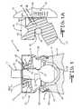
- FIG. 1is a side elevational view, partially in cross section, of a ball and socket joint including a first embodiment of a sealing structure in accordance with this invention.
- FIG. 1Ais an enlarged elevational view, partially in cross section, of a portion of the first embodiment of a sealing structure illustrated in FIG. 1 .
- FIG. 2is a side elevational view, partially in cross section, of the ball and socket joint and sealing structure illustrated in FIG. 1 shown assembled between first and second components and in an unarticulated condition.
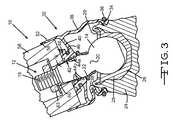
- FIG. 3is a side elevational view, partially in cross section, of the ball and socket joint and sealing structure of FIGS. 1 and 2 shown in an articulated condition.
- FIG. 4is a side elevational view, partially in cross section, of a ball and socket joint including a second embodiment of a sealing structure in accordance with this invention.
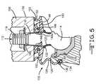
- FIG. 5is a side elevational view, partially in cross section, of the ball and socket joint and sealing structure illustrated in FIG. 4 shown assembled between first and second components and in an unarticulated condition.
- FIG. 6is a side elevational view, partially in cross section, of the ball and socket joint and sealing structure illustrated in FIGS. 4 and 5 shown in an articulated condition.
- FIGS. 1 , 2 , and 3there is illustrated in FIGS. 1 , 2 , and 3 a ball and socket joint, indicated generally at 10 , in accordance with this invention.
- the illustrated ball and socket joint 10is, in large measure, conventional in the art and is intended merely to illustrate one environment in which this invention may be used. Thus, the scope of this invention is not intended to be limited for use with the specific structure for the ball and socket joint 10 illustrated in FIG. 1 or with ball and socket joints in general. On the contrary, as will become apparent below, this invention may be used in any desired environment for the purposes described below.
- the illustrated ball and socket joint 10includes a ball stud portion, indicated generally at 12 , that includes a spherical ball 14 , an elongated stud 16 that extends from the spherical ball 14 , and a fastener end 18 that extends from the elongated stud 16 .
- the illustrated elongated stud 16tapers from a relatively larger end adjacent the spherical ball 14 to a relatively smaller end adjacent to the fastener end 18 , although such is not required.
- the fastener end 18can be externally threaded as shown or provided with any other conventional securement structure for a purpose that will be explained below.
- a reduced diameter region 20may be provided between the ball 14 and the portion of the elongated stud 16 adjacent thereto.
- the reduced diameter region 20may provide additional clearance to articulate the elongated stud 16 to extreme angular positions.
- a seal support collar 22may be positioned around the reduced diameter region 20 , if so desired, for a purpose that will be explained below.
- the seal support collar 22may alternatively be omitted altogether or positioned at any other desired point on the elongated stud 16 .
- the illustrated ball and socket joint 10also includes a socket housing 24 having a bushing socket 26 formed therein.
- the bushing socket 26has an open end and further defines an interior space that receives a bushing 28 therein.
- the bushing 28includes an outer surface that is positioned within the bushing socket 26 , an inner surface that supports the spherical ball 14 for relative rotation therewith, and an open end through which the elongated stud 16 extends.
- the bushing 28is conventional in the art and may be shaped other than illustrated if desired.
- the bushing 28can be retained within the bushing socket 26 by any retaining means such as, for example, a retaining lip 29 that may be formed integrally with the housing 24 as illustrated.
- the retaining meansmay be provided as a separate structure (such as, for example, a threaded cap, a snap ring, or other similar structure) that is connected to the bushing socket 26 to prevent the bushing 28 from being removed therefrom.
- the socket housing 24may further include a seal retaining groove 30 or other retaining structure for a purpose that will be explained below.
- the illustrated ball and socket joint 10includes a sealing structure, such as a boot and seal assembly, indicated generally at 32 .
- the boot and seal assembly 32includes a retaining end 34 that engages the socket housing 24 . As shown in FIGS. 1 , 2 , and 3 , the retaining end 34 of the boot and seal assembly 32 extends about and into the seal retaining groove 30 provided on the socket housing 24 .
- the retaining end 34 of the boot and seal assembly 32may further include a first retaining ring 36 or any other suitable retaining structure, though such is not required.
- the retaining end 34may function to seal out contamination, retain lubricant within the ball and socket joint 10 , and secure the boot and seal assembly 32 to the socket housing 24 .
- the illustrated boot and seal assembly 32further includes a body 38 that extends from the retaining end 34 .
- the illustrated body 38is generally hollow and cylindrical in shape, having a single rounded profile convolution. However, the body 38 may have any number of such convolutions having any desired geometry.
- the body 38is provided to allow deflection of portions of the boot and seal assembly 32 , while preventing a substantial separation of certain sealing surfaces from their respective seats, as described in detail below.
- the illustrated boot and seal assembly 32also includes a diaphragm 40 , which extends in a general radial direction from the body 38 toward the elongated stud 16 .
- the diaphragm 40is preferably formed integrally with the body 38 of the boot and seal assembly 32 , although such is not required, and includes a first seal portion, indicated generally at 42 , and a second seal portion, indicated generally at 48 .
- the first seal portion 42is a lip seal that includes a plurality of laterally spaced apart seal lips 44 a that surround and engage the outer surface of the elongated stud 16 .
- the seal lips 44may be concentric or of the same diameter, if so desired.
- the seal lips 44 aeach define a generally centrally-located seal lip longitudinal axis A that engages a sealing surface 16 a of the elongated stud 16 at an acute angle.
- the seal lips 44 aare separated by annular spaces 44 b that are illustrated disposed in an alternating arrangement therewith. The annular spaces 44 b permit the seal lips 44 a to deflect when sealing contact is made with the elongated stud 16 .
- the illustrated seal lips 44 ahave a radially elongated profile of a substantially uniform section (i.e. cross section) when measured parallel to the sealing surface of the elongated stud 16 .
- the geometry of the seal lips 44 afacilitates a shear loading thereof against the elongated stud 16 .
- Such a shear loading characteristicprovides a substantially constant sealing pressure against the mating seal surface over the range of deflections of the seal lips 44 a .
- the illustrated seal lips 44 aare further dimensioned to fit against the surface of the elongated stud 16 such that they may be deflected when engaged against the surface of the elongated stud 16 .
- the resilient nature of the seal materialprovides, in part, a sealing pressure for the seal lips 44 a against the surface of the elongated stud 16 .
- the first seal portion 42may be embodied as any desired structure or combination of structures.
- the first seal portion 42may, if desired, be urged inwardly into engagement with the outer surface of the elongated stud 16 by a second retaining ring 46 , that is conventional in the art.
- the second retaining ring 46may be configured as a resilient band such as, for example, a garter spring in the form of a wound coil spring having ends connected together to form a complete circular ring.
- the second retaining ring 46may be a closed ring structure or an open ended, solid ring structure having either overlapping or non-contacting ends.
- the second seal portion 48 of the diaphragm 40is a face seal that includes a plurality (two in the illustrated embodiment) of annular concentric projections 49 , though such a configuration is not required.
- the second sealing portion 42may be embodied as any structure suitable to seal against a portion of a mating component 58 (as shown in FIGS. 2 and 3 ) and restrict or prevent contaminant entry therebetween.
- the second seal portion 48is positioned adjacent to the diaphragm 40 and defines a groove 50 therebetween, in which the second retaining ring 46 may be disposed.
- the second seal portion 48further provides a supplemental sealing function that further prevents contaminant intrusion, as will be explained below.
- the boot and seal assembly 32further includes a third seal portion 52 that, in the first embodiment of this invention, is an outer sealing member.
- the third seal portion 52is illustrated as a generally hollow and cylindrical structure extending from the diaphragm 40 , although such is not required.
- the third sealing portion 52may be any shape that is suitable to engage an outer surface 56 of the mating component 58 , as will be explained below.
- the third sealing portion 52may be circular, oval, square, or hexagonal in cross section.
- the third sealing portion 52may be contoured to accommodate a projecting feature (not shown) that extends from the mating component 58 .
- the ball and socket joint 10is illustrated in an engaged relationship with the mating component 58 .
- the elongated stud 16 of the ball and socket joint 10extends through an aperture 60 provided in the mating component 58 .
- the second seal portion 48 of the boot and seal assembly 32engages an end surface 62 of the mating component 58 and functions to protect the first seal portion 42 from exposure to contaminants.
- the mating component 58is drawn into engagement on the elongated stud 16 (such as by a nut 63 threaded onto the fastener end 18 of the stud 16 )
- the first seal portion 42is pushed into sealing engagement with the outer surface of the elongated stud 16 .
- the second seal portion 48may be deflected against the end surface 62 of the mating component 58 . Sealing pressure is supplied, at least in part, by the restoring force of the resilient material of the boot and seal assembly 32 such that seal wear is compensated and contact remains between the first and second seal portions 42 and 48 , respectively, and the corresponding mating surfaces.
- the second seal portion 48may deflect the groove 50 to further trap and retain the second retaining ring 46 .
- Part of the first seal portion 42may locate against the seal support collar 22 in order to provide a seal stop position.
- the seal support collar 22also helps to maintain contact of the second seal portion 48 against the end surface 62 .
- FIG. 3illustrates the ball and socket joint 10 including the boot and seal assembly 32 and the mating component 58 in an articulated position.
- the portion of the body 38compresses or folds over substantially at the point where the ball stud portion 12 is articulated toward the socket housing 24 .
- another portion of the body 38at the opposite position of the ball stud portion 12 , is deflected away from the socket housing 24 .
- the third sealing portion 52engages the outer surface 56 sufficiently to maintain contact throughout the articulation of the ball and socket joint 10 .
- the first seal portion 42moves relative to the ball stud portion 12
- the second seal portion 48moves relative to the end surface 62
- the third seal portion 52moves relative to the mating component 58 .
- Small relative rotationsmay cause the third sealing portion 52 to remain substantially fixed to the mating component 58 while the body 38 deforms, though such a fixed relationship is not required.
- the seal lips 42may be deflected into the adjacent channels 44 b at initial installation.
- the seal lips 44 amay wear and deflect away from the channels 44 b .
- the sealing pressure and sealing capabilityis substantially constant.
- the constant pressure of the resilient material, loaded in shearprovides relatively constant seal wear compensation over the life of the seal. This pressure may be further augmented by the second retaining ring 46 .
- the first and second seal portions 42 and 48may have any sealing pressure profile or characteristic desired.
- FIG. 4there is illustrated a second embodiment of a ball and socket joint, shown generally at 110 .
- similar reference numbersare used to indicate common elements or features.
- the operation and relative connections of a ball stud portion 112 , a socket housing 124 , a bushing 128 , and a mating component 158are the same as described above in the first embodiment.
- the ball stud portion 112includes a spherical ball 114 , an elongated stud portion 116 , and a fastener end 118 .
- the ball stud portion 112may also include a reduced diameter region 120 and a seal support collar 122 .
- the socket housing 124includes a bushing socket 126 and may also include a retaining lip 129 if so desired.
- the mating component 158includes an outer surface 156 and an aperture 160 .
- the second embodiment of a boot and seal assembly 132includes similar elements and functionality to the first embodiment boot and seal assembly 32 described above. For example, a first end 134 is retained within a seal retaining groove 130 by a first retaining ring 136 . Also, a body 138 is deflected or articulated, as shown in FIGS. 5 and 6 , in a similar mode to the body 38 of the first embodiment. Some elements of the boot and seal assembly 132 are distinct from corresponding elements of the first embodiment boot and seal assembly 32 , as will be described below. Other elements of the second embodiment boot and seal assembly 132 may be alternative variations of the first embodiment boot and seal assembly 32 and, accordingly, may also be included thereon.
- the second embodiment of the boot and seal assembly 132includes a diaphragm 140 , as shown in FIG. 4 .
- the diaphragm 140includes a first seal portion 142 and a second seal portion 148 that are similar in layout, function, and operational characteristics to the first seal portion 42 and the second seal portion 48 described above.
- a second retaining ring 146is contained within a groove 150 defined between the diaphragm 140 and the second seal portion 148 .
- the structure and function of the second retaining ring 146is similar to the second retaining ring 46 of the first embodiment.
- the first seal portion 142includes a plurality of seal lips 144 a and alternating channels 144 b . Though illustrated as being configured similarly to the first seal portion 42 of FIG. 1A , such is not required.
- the diaphragm 140further includes a third seal portion 152 .
- the third seal portion 152is illustrated in FIG. 4 as extending from the diaphragm 142 , though such is not required. Rather, the third seal portion 152 may extend from any suitable point on the body 138 or the diaphragm 140 . Additionally, though the third seal portion 152 is shown integrally formed with the diaphragm 140 , such is not required.
- the third seal portion 152may be a separate structure and may also be fitted about the second seal portion 148 or the groove 150 , if so desired.
- FIG. 5illustrates the second embodiment of the boot and seal assembly 132 in a deflected state with the installed mating component 158 , similar to that of the first embodiment as described above.
- the third seal portion 152engages a portion of the mating component end surface 162 .
- the third seal portion 152is further compressed against the end surface 162 as the mating component 158 engages the ball stud portion 112 .
- the first seal portion 142engages the elongated stud 116 of the ball stud portion 112 and the second seal portion 148 engages the end surface 162 of the mating component 158 , as described above in the first embodiment.
- the third seal portion 152may bulge outwardly or have a convoluted profile that locates on the end surface 162 .
- FIG. 6illustrates the ball and socket joint 110 , the boot and seal assembly 132 , and the mating component 158 in an articulated position, which is similar to FIG. 3 .
- the third seal portion 152exhibits more compressive deflection at the point where the ball stud portion 112 is articulated closer to the socket housing 124 .
- the opposite side of the third seal portion 152expands, or returns to an approximated free state condition in order to follow the end surface 162 of the mating component 158 .
- the tip of the third seal portion 152may unseat from the end surface 162 .
- the third seal portion 152may be configured so as to remain fully in contact with the end surface 162 .
- the first embodiment boot and seal assembly 32 and the second embodiment boot and seal assembly 132may be made from any suitable elastomeric material such as, for example, natural rubber; fluoroelastomer synthetic rubber such as, for example, Viton®; chloroprene synthetic rubber, such as, for example, Neoprene®; and thermoplastic elastomers such as, for example, Hytrel® and Santoprene®.
- suitable elastomeric materialsuch as, for example, natural rubber; fluoroelastomer synthetic rubber such as, for example, Viton®; chloroprene synthetic rubber, such as, for example, Neoprene®; and thermoplastic elastomers such as, for example, Hytrel® and Santoprene®.
- the materials presentedare not intended to be exhaustive, but merely indicative of various classes of flexible, water-impervious materials that may suitable for such boot configurations. Other flexible materials may be used, if so desired.
- the embodiments of the boot and seal assemblies 32 and 132may further be made by
Landscapes
- Engineering & Computer Science (AREA)
- General Engineering & Computer Science (AREA)
- Mechanical Engineering (AREA)
- Pivots And Pivotal Connections (AREA)
- Sealing Devices (AREA)
Abstract
Description
Claims (13)
Priority Applications (2)
| Application Number | Priority Date | Filing Date | Title |
|---|---|---|---|
| US12/267,008US8414215B2 (en) | 2008-11-07 | 2008-11-07 | Sealing structure for use with a ball and socket joint |
| PCT/US2009/063517WO2010054171A2 (en) | 2008-11-07 | 2009-11-06 | Sealing structure for use with a ball and socket joint |
Applications Claiming Priority (1)
| Application Number | Priority Date | Filing Date | Title |
|---|---|---|---|
| US12/267,008US8414215B2 (en) | 2008-11-07 | 2008-11-07 | Sealing structure for use with a ball and socket joint |
Publications (2)
| Publication Number | Publication Date |
|---|---|
| US20100119297A1 US20100119297A1 (en) | 2010-05-13 |
| US8414215B2true US8414215B2 (en) | 2013-04-09 |
Family
ID=42153576
Family Applications (1)
| Application Number | Title | Priority Date | Filing Date |
|---|---|---|---|
| US12/267,008Expired - Fee RelatedUS8414215B2 (en) | 2008-11-07 | 2008-11-07 | Sealing structure for use with a ball and socket joint |
Country Status (2)
| Country | Link |
|---|---|
| US (1) | US8414215B2 (en) |
| WO (1) | WO2010054171A2 (en) |
Cited By (6)
| Publication number | Priority date | Publication date | Assignee | Title |
|---|---|---|---|---|
| US20130287478A1 (en)* | 2012-04-25 | 2013-10-31 | Jtekt Corporation | Ball joint |
| CN104169594A (en)* | 2012-05-25 | 2014-11-26 | 株式会社索密克石川 | ball joint |
| US20160131182A1 (en)* | 2013-08-06 | 2016-05-12 | Kabushiki Kaisha Somic Ishikawa | Ball joint and method of manufacturing the same |
| US9863464B2 (en)* | 2014-10-22 | 2018-01-09 | Nok Corporation | Dust cover |
| US10364838B2 (en) | 2016-03-22 | 2019-07-30 | Federal-Mogul Motorparts Llc | Boot for a socket assembly |
| US20210018038A1 (en)* | 2018-10-11 | 2021-01-21 | Nok Corporation | Ball joint and dust cover |
Families Citing this family (8)
| Publication number | Priority date | Publication date | Assignee | Title |
|---|---|---|---|---|
| US20090289424A1 (en)* | 2008-05-20 | 2009-11-26 | Freudenberg-Nok General Partnership | Ball Joint Dust Seal With Lubricating Flutes |
| DE202008012454U1 (en)* | 2008-09-18 | 2008-12-04 | Mvs Dynalink Europe Gmbh | Device consisting of at least a first and a second machine part |
| KR200460981Y1 (en) | 2012-02-29 | 2012-06-14 | (주)삼우 | Ball joint |
| US9109702B2 (en)* | 2013-03-21 | 2015-08-18 | Caterpillar Inc. | Boot seal for machine system and method |
| EP3034897B1 (en) | 2014-12-15 | 2020-04-08 | Roller Bearing Company of America, Inc. | Spherical bearing with annular seal having an auxiliary seal leg extending therefrom |
| US9790983B2 (en)* | 2015-05-21 | 2017-10-17 | Federal-Mogul Motorparts Corporation | Movable joint assembly |
| JP6909352B2 (en) | 2017-08-16 | 2021-07-28 | マルチマティック インコーポレーテッドMultimatic Inc. | Ball joint with injection molded bearing and its manufacturing method |
| DE102018122495B4 (en)* | 2018-09-14 | 2022-02-03 | Carl Freudenberg Kg | Sealing bellows and seal assembly comprising the sealing bellows |
Citations (65)
| Publication number | Priority date | Publication date | Assignee | Title |
|---|---|---|---|---|
| US2643147A (en)* | 1948-09-01 | 1953-06-23 | Gen Motors Corp | Packing |
| US2786359A (en)* | 1955-01-14 | 1957-03-26 | Panseal Inc | Waterproof panel seal nut |
| US2793889A (en)* | 1951-04-12 | 1957-05-28 | Houdaille Industries Inc | Piston rod seal |
| US3144256A (en)* | 1962-08-06 | 1964-08-11 | Clarence E Wright | Free piston seal |
| US3187590A (en)* | 1962-08-31 | 1965-06-08 | Watts Electric & Mfg Co | Lubricating assembly having a pressure venting seal |
| US3279832A (en)* | 1964-03-20 | 1966-10-18 | Ford Motor Co | Seal for ball and socket joint |
| US3368650A (en)* | 1965-03-24 | 1968-02-13 | Wasdell William Kenneth | Seal means for shock absorbers |
| US3973781A (en)* | 1972-05-23 | 1976-08-10 | Veb Gummikombinat Berlin | Self-lubricating seal |
| US4241928A (en)* | 1978-12-07 | 1980-12-30 | Yasunori Hamaguchi | Boot seal |
| US4650362A (en)* | 1985-06-03 | 1987-03-17 | Honda Giken Kogyo Kabushiki Kaisha | Ball joint |
| US4678064A (en)* | 1984-05-25 | 1987-07-07 | Aisin Seiki Kabushiki Kaisha | Sealing boot for use in disc brake assembly |
| US4695061A (en)* | 1985-08-29 | 1987-09-22 | Eagle-Picher Industries, Inc. | Valve stem seal |
| US4744571A (en)* | 1986-07-08 | 1988-05-17 | Geberth John Daniel Jun | Self-compensating seal with biased sealing wipers |
| US4852891A (en)* | 1985-01-10 | 1989-08-01 | Toyoda Gosei Co., Ltd. | Plastic boots and method of manufacturing the same |
| US4865170A (en)* | 1987-11-25 | 1989-09-12 | Monroe Auto Equipment Company | Method and apparatus for sealing |
| US4869514A (en)* | 1986-09-10 | 1989-09-26 | Ha Rubber And Plastics (Pty) Ltd. | Contact seal |
| US4886281A (en)* | 1985-12-21 | 1989-12-12 | Firma Carl Freudenberg | Sealing ring having a sealing surfacer with a recessional annular projection |
| US4921368A (en)* | 1987-12-07 | 1990-05-01 | Trw Ehrenreich Gmbh & Co. Kg | Fastening of a sealing bellows to the joint housing of a ball joint |
| US4995623A (en)* | 1987-09-11 | 1991-02-26 | Nok Corporation | Sealing device for reciprocating member |
| US5066159A (en)* | 1991-02-08 | 1991-11-19 | Trw Inc. | Ball joint with integral seal |
| US5380114A (en) | 1993-01-25 | 1995-01-10 | Trw Inc. | Ball joint assembly and method of mounting |
| US5498092A (en)* | 1994-06-23 | 1996-03-12 | Trw Inc. | Protective cover for a ball joint assembly |
| US5558580A (en)* | 1993-12-15 | 1996-09-24 | Nok Corporation | Boot |
| US5601378A (en)* | 1994-12-08 | 1997-02-11 | Kabushiki Kaisha Somic Ishikawa | Rod-end bearing device |
| US5678947A (en) | 1995-09-26 | 1997-10-21 | Trw Inc. | Joint assembly |
| US5855448A (en)* | 1997-10-20 | 1999-01-05 | Ford Global Technologies, Inc. | Ball joint assembly |
| US5882137A (en)* | 1996-06-25 | 1999-03-16 | Lemforder Metallwaren Ag | Process for preparing a low-friction ball joint, as well as low-friction ball joint |
| DE19803056A1 (en) | 1998-01-28 | 1999-07-29 | Trw Fahrwerksyst Gmbh & Co | Procedure for determining a bearing shell of a ball joint |
| US5931597A (en) | 1997-10-16 | 1999-08-03 | Trw Inc. | Ball joint |
| US5997208A (en) | 1998-06-02 | 1999-12-07 | Trw Inc. | Adjustment for a ball joint assembly |
| US6010271A (en) | 1996-02-01 | 2000-01-04 | Trw Inc. | Joint assembly |
| US6168164B1 (en)* | 1998-12-08 | 2001-01-02 | Federal-Mogul World Wide, Inc. | Hydrodynamic seal and method of manufacture |
| US6250840B1 (en) | 1998-09-11 | 2001-06-26 | Trw Inc. | Tie rod end |
| US6254114B1 (en) | 1998-11-09 | 2001-07-03 | American Axle & Manufacturing, Inc. | Composite stabilizer bar link |
| US6276702B1 (en)* | 1999-08-09 | 2001-08-21 | Ford Global Technologies, Inc. | Wheel suspension assembly |
| US6308959B1 (en)* | 1997-06-27 | 2001-10-30 | ZF Lemförder Metallwaren AG | Elastic sealing element in the form of bellows |
| US6334620B1 (en)* | 1997-12-23 | 2002-01-01 | Trw Fahrwerksysteme Gmbh & Co. Kg | Bellows seal for pivot joints, especially in automobiles |
| US6502831B2 (en) | 2001-01-29 | 2003-01-07 | Trw Inc. | Ball joint with seal |
| US6527468B1 (en) | 2001-10-09 | 2003-03-04 | Trw Inc. | Ball joint with dual tapered stud connection |
| US6582146B2 (en) | 2001-02-13 | 2003-06-24 | Trw Inc. | Ball joint seal |
| US20030160397A1 (en)* | 2002-01-15 | 2003-08-28 | David Sakata | Vibrationally decoupling gasket |
| US6652179B2 (en)* | 2000-07-28 | 2003-11-25 | Dana Industrial S/A | Sealing cap for ball joint assembly |
| US20030222412A1 (en)* | 2002-05-28 | 2003-12-04 | Trw Inc. | Ball joint seal |
| US6773197B2 (en) | 2002-10-09 | 2004-08-10 | Trw Inc. | Ball joint |
| US6814521B2 (en)* | 2002-02-21 | 2004-11-09 | Musashi Seimitsu Industry Co., Ltd. | Ball joint |
| US20040232629A1 (en)* | 2002-03-28 | 2004-11-25 | Stefan Schonhoff | Sealing bellows with snap-on connection |
| US20050036827A1 (en)* | 2002-09-11 | 2005-02-17 | Zf Lemforder Metallwaren Ag. | Ball and socket joint protective cap |
| US6860486B2 (en)* | 2001-11-08 | 2005-03-01 | Dichtungstechnik G. Bruss Gmbh & Co. Kg | Shaft sealing ring |
| US6935803B2 (en)* | 2001-06-11 | 2005-08-30 | ZF Lemförder Metallwaren AG | Joint, particularly a ball-and-socket joint for chassis parts in a motor vehicle |
| US20050207830A1 (en)* | 2003-02-27 | 2005-09-22 | Zf Lemforder Metallwaren Ag | Ball and socket joint |
| US7004471B2 (en)* | 2003-12-17 | 2006-02-28 | General Motors Corporation | Radial lip seal |
| US20060193680A1 (en)* | 2003-04-07 | 2006-08-31 | Kabushiki Kaisha Somic Ishikawa | Ball Joint |
| WO2007012396A1 (en)* | 2005-07-27 | 2007-02-01 | Trw Automotive Gmbh | Ball joint and sealing collar for a ball joint of this type |
| US20070048081A1 (en)* | 2005-08-25 | 2007-03-01 | James Elterman | Dust boot with grease relief passage |
| US20070065227A1 (en)* | 2005-09-20 | 2007-03-22 | Sellers Roger G | Cone adaptor for ball joint studs, tie rods, sway bar links and the like |
| US20070140783A1 (en)* | 2005-12-15 | 2007-06-21 | O' Bryan Timothy S | Ball joint assembly with secondary liner |
| US7237978B2 (en)* | 2004-07-22 | 2007-07-03 | ZF Lemförder Metallwaren AG | Joint sealing bellows with sealing ring and assembly/installation method |
| US20070166096A1 (en)* | 2005-06-03 | 2007-07-19 | Lim Chong K | Joint assembly |
| US20080038051A1 (en)* | 2004-09-24 | 2008-02-14 | Klaus Broker | Ball and Socket Joint with a Sealing Bellows |
| US20080056811A1 (en)* | 2006-09-06 | 2008-03-06 | Trw Automotive U.S. Llc | Ball joint |
| US7367743B2 (en) | 2003-07-28 | 2008-05-06 | Trw Automotive Gmbh | Ball joint and a component with ball joint |
| US7465100B2 (en)* | 2002-09-09 | 2008-12-16 | Nok Corporation | Sealing apparatus |
| US20090209353A1 (en) | 2006-08-25 | 2009-08-20 | Olaf Abels | Sealing bellows or bellows |
| US20100237567A1 (en)* | 2007-08-02 | 2010-09-23 | Kurth Juergen | Sealing element |
| US7959159B2 (en)* | 2006-11-23 | 2011-06-14 | Elringklinger Ag | Sealing arrangement |
- 2008
- 2008-11-07USUS12/267,008patent/US8414215B2/ennot_activeExpired - Fee Related
- 2009
- 2009-11-06WOPCT/US2009/063517patent/WO2010054171A2/enactiveApplication Filing
Patent Citations (68)
| Publication number | Priority date | Publication date | Assignee | Title |
|---|---|---|---|---|
| US2643147A (en)* | 1948-09-01 | 1953-06-23 | Gen Motors Corp | Packing |
| US2793889A (en)* | 1951-04-12 | 1957-05-28 | Houdaille Industries Inc | Piston rod seal |
| US2786359A (en)* | 1955-01-14 | 1957-03-26 | Panseal Inc | Waterproof panel seal nut |
| US3144256A (en)* | 1962-08-06 | 1964-08-11 | Clarence E Wright | Free piston seal |
| US3187590A (en)* | 1962-08-31 | 1965-06-08 | Watts Electric & Mfg Co | Lubricating assembly having a pressure venting seal |
| US3279832A (en)* | 1964-03-20 | 1966-10-18 | Ford Motor Co | Seal for ball and socket joint |
| US3368650A (en)* | 1965-03-24 | 1968-02-13 | Wasdell William Kenneth | Seal means for shock absorbers |
| US3973781A (en)* | 1972-05-23 | 1976-08-10 | Veb Gummikombinat Berlin | Self-lubricating seal |
| US4241928A (en)* | 1978-12-07 | 1980-12-30 | Yasunori Hamaguchi | Boot seal |
| US4678064A (en)* | 1984-05-25 | 1987-07-07 | Aisin Seiki Kabushiki Kaisha | Sealing boot for use in disc brake assembly |
| US4852891A (en)* | 1985-01-10 | 1989-08-01 | Toyoda Gosei Co., Ltd. | Plastic boots and method of manufacturing the same |
| US4650362A (en)* | 1985-06-03 | 1987-03-17 | Honda Giken Kogyo Kabushiki Kaisha | Ball joint |
| US4695061A (en)* | 1985-08-29 | 1987-09-22 | Eagle-Picher Industries, Inc. | Valve stem seal |
| US4886281A (en)* | 1985-12-21 | 1989-12-12 | Firma Carl Freudenberg | Sealing ring having a sealing surfacer with a recessional annular projection |
| US4744571A (en)* | 1986-07-08 | 1988-05-17 | Geberth John Daniel Jun | Self-compensating seal with biased sealing wipers |
| US4869514A (en)* | 1986-09-10 | 1989-09-26 | Ha Rubber And Plastics (Pty) Ltd. | Contact seal |
| US4995623A (en)* | 1987-09-11 | 1991-02-26 | Nok Corporation | Sealing device for reciprocating member |
| US4865170A (en)* | 1987-11-25 | 1989-09-12 | Monroe Auto Equipment Company | Method and apparatus for sealing |
| US4921368A (en)* | 1987-12-07 | 1990-05-01 | Trw Ehrenreich Gmbh & Co. Kg | Fastening of a sealing bellows to the joint housing of a ball joint |
| US5066159A (en)* | 1991-02-08 | 1991-11-19 | Trw Inc. | Ball joint with integral seal |
| US5380114A (en) | 1993-01-25 | 1995-01-10 | Trw Inc. | Ball joint assembly and method of mounting |
| US5558580A (en)* | 1993-12-15 | 1996-09-24 | Nok Corporation | Boot |
| US5498092A (en)* | 1994-06-23 | 1996-03-12 | Trw Inc. | Protective cover for a ball joint assembly |
| US5601378A (en)* | 1994-12-08 | 1997-02-11 | Kabushiki Kaisha Somic Ishikawa | Rod-end bearing device |
| US5678947A (en) | 1995-09-26 | 1997-10-21 | Trw Inc. | Joint assembly |
| US6010271A (en) | 1996-02-01 | 2000-01-04 | Trw Inc. | Joint assembly |
| US5882137A (en)* | 1996-06-25 | 1999-03-16 | Lemforder Metallwaren Ag | Process for preparing a low-friction ball joint, as well as low-friction ball joint |
| US6308959B1 (en)* | 1997-06-27 | 2001-10-30 | ZF Lemförder Metallwaren AG | Elastic sealing element in the form of bellows |
| US5931597A (en) | 1997-10-16 | 1999-08-03 | Trw Inc. | Ball joint |
| US5855448A (en)* | 1997-10-20 | 1999-01-05 | Ford Global Technologies, Inc. | Ball joint assembly |
| US6334620B1 (en)* | 1997-12-23 | 2002-01-01 | Trw Fahrwerksysteme Gmbh & Co. Kg | Bellows seal for pivot joints, especially in automobiles |
| DE19803056A1 (en) | 1998-01-28 | 1999-07-29 | Trw Fahrwerksyst Gmbh & Co | Procedure for determining a bearing shell of a ball joint |
| US5997208A (en) | 1998-06-02 | 1999-12-07 | Trw Inc. | Adjustment for a ball joint assembly |
| US6250840B1 (en) | 1998-09-11 | 2001-06-26 | Trw Inc. | Tie rod end |
| US6254114B1 (en) | 1998-11-09 | 2001-07-03 | American Axle & Manufacturing, Inc. | Composite stabilizer bar link |
| US6168164B1 (en)* | 1998-12-08 | 2001-01-02 | Federal-Mogul World Wide, Inc. | Hydrodynamic seal and method of manufacture |
| US6276702B1 (en)* | 1999-08-09 | 2001-08-21 | Ford Global Technologies, Inc. | Wheel suspension assembly |
| US6652179B2 (en)* | 2000-07-28 | 2003-11-25 | Dana Industrial S/A | Sealing cap for ball joint assembly |
| US6502831B2 (en) | 2001-01-29 | 2003-01-07 | Trw Inc. | Ball joint with seal |
| US6582146B2 (en) | 2001-02-13 | 2003-06-24 | Trw Inc. | Ball joint seal |
| US6935803B2 (en)* | 2001-06-11 | 2005-08-30 | ZF Lemförder Metallwaren AG | Joint, particularly a ball-and-socket joint for chassis parts in a motor vehicle |
| US6527468B1 (en) | 2001-10-09 | 2003-03-04 | Trw Inc. | Ball joint with dual tapered stud connection |
| US6860486B2 (en)* | 2001-11-08 | 2005-03-01 | Dichtungstechnik G. Bruss Gmbh & Co. Kg | Shaft sealing ring |
| US20030160397A1 (en)* | 2002-01-15 | 2003-08-28 | David Sakata | Vibrationally decoupling gasket |
| US6814521B2 (en)* | 2002-02-21 | 2004-11-09 | Musashi Seimitsu Industry Co., Ltd. | Ball joint |
| US20040232629A1 (en)* | 2002-03-28 | 2004-11-25 | Stefan Schonhoff | Sealing bellows with snap-on connection |
| US7192214B2 (en)* | 2002-03-28 | 2007-03-20 | ZF Lemörder Metallwaren AG | Sealing bellows with snap-on connection |
| US6834863B2 (en)* | 2002-05-28 | 2004-12-28 | Trw Inc. | Ball joint seal |
| US20030222412A1 (en)* | 2002-05-28 | 2003-12-04 | Trw Inc. | Ball joint seal |
| US7465100B2 (en)* | 2002-09-09 | 2008-12-16 | Nok Corporation | Sealing apparatus |
| US20050036827A1 (en)* | 2002-09-11 | 2005-02-17 | Zf Lemforder Metallwaren Ag. | Ball and socket joint protective cap |
| US6773197B2 (en) | 2002-10-09 | 2004-08-10 | Trw Inc. | Ball joint |
| US20050207830A1 (en)* | 2003-02-27 | 2005-09-22 | Zf Lemforder Metallwaren Ag | Ball and socket joint |
| US20060193680A1 (en)* | 2003-04-07 | 2006-08-31 | Kabushiki Kaisha Somic Ishikawa | Ball Joint |
| US7367743B2 (en) | 2003-07-28 | 2008-05-06 | Trw Automotive Gmbh | Ball joint and a component with ball joint |
| US7004471B2 (en)* | 2003-12-17 | 2006-02-28 | General Motors Corporation | Radial lip seal |
| US7237978B2 (en)* | 2004-07-22 | 2007-07-03 | ZF Lemförder Metallwaren AG | Joint sealing bellows with sealing ring and assembly/installation method |
| US20080038051A1 (en)* | 2004-09-24 | 2008-02-14 | Klaus Broker | Ball and Socket Joint with a Sealing Bellows |
| US20070166096A1 (en)* | 2005-06-03 | 2007-07-19 | Lim Chong K | Joint assembly |
| WO2007012396A1 (en)* | 2005-07-27 | 2007-02-01 | Trw Automotive Gmbh | Ball joint and sealing collar for a ball joint of this type |
| US20100086347A1 (en)* | 2005-07-27 | 2010-04-08 | Peter Bernhardt | Ball Joint and Sealing Collar for Such a Ball Joint |
| US20070048081A1 (en)* | 2005-08-25 | 2007-03-01 | James Elterman | Dust boot with grease relief passage |
| US20070065227A1 (en)* | 2005-09-20 | 2007-03-22 | Sellers Roger G | Cone adaptor for ball joint studs, tie rods, sway bar links and the like |
| US20070140783A1 (en)* | 2005-12-15 | 2007-06-21 | O' Bryan Timothy S | Ball joint assembly with secondary liner |
| US20090209353A1 (en) | 2006-08-25 | 2009-08-20 | Olaf Abels | Sealing bellows or bellows |
| US20080056811A1 (en)* | 2006-09-06 | 2008-03-06 | Trw Automotive U.S. Llc | Ball joint |
| US7959159B2 (en)* | 2006-11-23 | 2011-06-14 | Elringklinger Ag | Sealing arrangement |
| US20100237567A1 (en)* | 2007-08-02 | 2010-09-23 | Kurth Juergen | Sealing element |
Non-Patent Citations (1)
| Title |
|---|
| PCT International Search Report (PCT/US2009/063517). |
Cited By (10)
| Publication number | Priority date | Publication date | Assignee | Title |
|---|---|---|---|---|
| US20130287478A1 (en)* | 2012-04-25 | 2013-10-31 | Jtekt Corporation | Ball joint |
| CN104169594A (en)* | 2012-05-25 | 2014-11-26 | 株式会社索密克石川 | ball joint |
| US20160177999A1 (en)* | 2012-05-25 | 2016-06-23 | Kabushiki Kaisha Somic Ishikawa | Ball joint |
| US9863463B2 (en)* | 2012-05-25 | 2018-01-09 | Kabushiki Kaisha Somic Ishikawa | Ball joint |
| US20160131182A1 (en)* | 2013-08-06 | 2016-05-12 | Kabushiki Kaisha Somic Ishikawa | Ball joint and method of manufacturing the same |
| US10047788B2 (en)* | 2013-08-06 | 2018-08-14 | Kabushiki Kaisha Somic Ishikawa | Ball joint and method of manufacturing the same |
| US9863464B2 (en)* | 2014-10-22 | 2018-01-09 | Nok Corporation | Dust cover |
| US10364838B2 (en) | 2016-03-22 | 2019-07-30 | Federal-Mogul Motorparts Llc | Boot for a socket assembly |
| US20210018038A1 (en)* | 2018-10-11 | 2021-01-21 | Nok Corporation | Ball joint and dust cover |
| US11739791B2 (en)* | 2018-10-11 | 2023-08-29 | Nok Corporation | Ball joint and dust cover |
Also Published As
| Publication number | Publication date |
|---|---|
| WO2010054171A2 (en) | 2010-05-14 |
| US20100119297A1 (en) | 2010-05-13 |
| WO2010054171A3 (en) | 2010-08-05 |
Similar Documents
| Publication | Publication Date | Title |
|---|---|---|
| US8414215B2 (en) | Sealing structure for use with a ball and socket joint | |
| JP3965136B2 (en) | Ball joint seal | |
| US3381987A (en) | Double wall seal for articulated joints | |
| US8047739B2 (en) | Metal split bearing compression load ball joint | |
| US3403932A (en) | Pressure relief boot seal | |
| US6171012B1 (en) | Radial ball-and-socket joint for a motor vehicle | |
| US9394998B2 (en) | Radial shaft seal assembly with snap in auxiliary member | |
| US5678947A (en) | Joint assembly | |
| JP6607920B2 (en) | Dust boots for movable joints | |
| CN1229460A (en) | Bellows Elastomeric Seals | |
| CN111065830B (en) | Improved socket assembly and method of manufacture | |
| EP3433503B1 (en) | Boot for a socket assembly | |
| US11629784B2 (en) | Sealing ring and use thereof | |
| CA2604121A1 (en) | Metal split bearing compression load ball joint | |
| US20030202842A1 (en) | Ball-and-socket joint | |
| US20050173869A1 (en) | Spark plug tube seal | |
| US7753377B2 (en) | Shaft seal having shaft offset compensating capability | |
| JPS608380B2 (en) | Valve sealing device | |
| JPS62137408A (en) | Dust cover for ball joint | |
| US20180355908A1 (en) | Ball joint for a two-point link and two-point-link with such ball joint | |
| CN108278367B (en) | Radial Displaceable Seal Assembly for Shafts | |
| JP2019138432A (en) | Sliding bearing | |
| EP3561329B1 (en) | Boot assembly for a joint member | |
| US20080304902A1 (en) | Ball joint | |
| ES2988508T3 (en) | Sealing ring and its use |
Legal Events
| Date | Code | Title | Description |
|---|---|---|---|
| AS | Assignment | Owner name:TRW AUTOMOTIVE U.S. LLC,MICHIGAN Free format text:ASSIGNMENT OF ASSIGNORS INTEREST;ASSIGNOR:LANGENDOEN, KEN;REEL/FRAME:021804/0083 Effective date:20081031 Owner name:TRW AUTOMOTIVE U.S. LLC, MICHIGAN Free format text:ASSIGNMENT OF ASSIGNORS INTEREST;ASSIGNOR:LANGENDOEN, KEN;REEL/FRAME:021804/0083 Effective date:20081031 | |
| STCF | Information on status: patent grant | Free format text:PATENTED CASE | |
| AS | Assignment | Owner name:THK RHYTHM AUTOMOTIVE GMBH, GERMANY Free format text:ASSIGNMENT OF ASSIGNORS INTEREST;ASSIGNOR:TRW AUTOMOTIVE U.S. LLC;REEL/FRAME:039639/0184 Effective date:20160803 | |
| FPAY | Fee payment | Year of fee payment:4 | |
| AS | Assignment | Owner name:THK RHYTHM AUTOMOTIVE GMBH, GERMANY Free format text:CHANGE OF ADDRESS;ASSIGNOR:THK RHYTHM AUTOMOTIVE GMBH;REEL/FRAME:048148/0880 Effective date:20170808 | |
| AS | Assignment | Owner name:THK RHYTHM AUTOMOTIVE GMBH, GERMANY Free format text:CHANGE OF ADDRESS;ASSIGNOR:THK RHYTHM AUTOMOTIVE GMBH;REEL/FRAME:048077/0262 Effective date:20170808 | |
| MAFP | Maintenance fee payment | Free format text:PAYMENT OF MAINTENANCE FEE, 8TH YEAR, LARGE ENTITY (ORIGINAL EVENT CODE: M1552); ENTITY STATUS OF PATENT OWNER: LARGE ENTITY Year of fee payment:8 | |
| FEPP | Fee payment procedure | Free format text:MAINTENANCE FEE REMINDER MAILED (ORIGINAL EVENT CODE: REM.); ENTITY STATUS OF PATENT OWNER: LARGE ENTITY | |
| LAPS | Lapse for failure to pay maintenance fees | Free format text:PATENT EXPIRED FOR FAILURE TO PAY MAINTENANCE FEES (ORIGINAL EVENT CODE: EXP.); ENTITY STATUS OF PATENT OWNER: LARGE ENTITY | |
| STCH | Information on status: patent discontinuation | Free format text:PATENT EXPIRED DUE TO NONPAYMENT OF MAINTENANCE FEES UNDER 37 CFR 1.362 | |
| FP | Lapsed due to failure to pay maintenance fee | Effective date:20250409 |