US8413777B2 - High efficiency hydraulic transmission control system - Google Patents
High efficiency hydraulic transmission control systemDownload PDFInfo
- Publication number
- US8413777B2 US8413777B2US12/707,414US70741410AUS8413777B2US 8413777 B2US8413777 B2US 8413777B2US 70741410 AUS70741410 AUS 70741410AUS 8413777 B2US8413777 B2US 8413777B2
- Authority
- US
- United States
- Prior art keywords
- fluid
- valve
- fluid communication
- pair
- control system
- Prior art date
- Legal status (The legal status is an assumption and is not a legal conclusion. Google has not performed a legal analysis and makes no representation as to the accuracy of the status listed.)
- Expired - Fee Related, expires
Links
Images


Classifications
- F—MECHANICAL ENGINEERING; LIGHTING; HEATING; WEAPONS; BLASTING
- F16—ENGINEERING ELEMENTS AND UNITS; GENERAL MEASURES FOR PRODUCING AND MAINTAINING EFFECTIVE FUNCTIONING OF MACHINES OR INSTALLATIONS; THERMAL INSULATION IN GENERAL
- F16H—GEARING
- F16H61/00—Control functions within control units of change-speed- or reversing-gearings for conveying rotary motion ; Control of exclusively fluid gearing, friction gearing, gearings with endless flexible members or other particular types of gearing
- F16H61/02—Control functions within control units of change-speed- or reversing-gearings for conveying rotary motion ; Control of exclusively fluid gearing, friction gearing, gearings with endless flexible members or other particular types of gearing characterised by the signals used
- F16H61/0202—Control functions within control units of change-speed- or reversing-gearings for conveying rotary motion ; Control of exclusively fluid gearing, friction gearing, gearings with endless flexible members or other particular types of gearing characterised by the signals used the signals being electric
- F16H61/0204—Control functions within control units of change-speed- or reversing-gearings for conveying rotary motion ; Control of exclusively fluid gearing, friction gearing, gearings with endless flexible members or other particular types of gearing characterised by the signals used the signals being electric for gearshift control, e.g. control functions for performing shifting or generation of shift signal
- F16H61/0206—Layout of electro-hydraulic control circuits, e.g. arrangement of valves
- F—MECHANICAL ENGINEERING; LIGHTING; HEATING; WEAPONS; BLASTING
- F16—ENGINEERING ELEMENTS AND UNITS; GENERAL MEASURES FOR PRODUCING AND MAINTAINING EFFECTIVE FUNCTIONING OF MACHINES OR INSTALLATIONS; THERMAL INSULATION IN GENERAL
- F16H—GEARING
- F16H61/00—Control functions within control units of change-speed- or reversing-gearings for conveying rotary motion ; Control of exclusively fluid gearing, friction gearing, gearings with endless flexible members or other particular types of gearing
- F16H61/68—Control functions within control units of change-speed- or reversing-gearings for conveying rotary motion ; Control of exclusively fluid gearing, friction gearing, gearings with endless flexible members or other particular types of gearing specially adapted for stepped gearings
- F16H61/684—Control functions within control units of change-speed- or reversing-gearings for conveying rotary motion ; Control of exclusively fluid gearing, friction gearing, gearings with endless flexible members or other particular types of gearing specially adapted for stepped gearings without interruption of drive
- F16H61/688—Control functions within control units of change-speed- or reversing-gearings for conveying rotary motion ; Control of exclusively fluid gearing, friction gearing, gearings with endless flexible members or other particular types of gearing specially adapted for stepped gearings without interruption of drive with two inputs, e.g. selection of one of two torque-flow paths by clutches
- F—MECHANICAL ENGINEERING; LIGHTING; HEATING; WEAPONS; BLASTING
- F16—ENGINEERING ELEMENTS AND UNITS; GENERAL MEASURES FOR PRODUCING AND MAINTAINING EFFECTIVE FUNCTIONING OF MACHINES OR INSTALLATIONS; THERMAL INSULATION IN GENERAL
- F16H—GEARING
- F16H61/00—Control functions within control units of change-speed- or reversing-gearings for conveying rotary motion ; Control of exclusively fluid gearing, friction gearing, gearings with endless flexible members or other particular types of gearing
- F16H61/0021—Generation or control of line pressure
- F16H61/0025—Supply of control fluid; Pumps therefor
- F16H2061/0034—Accumulators for fluid pressure supply; Control thereof
- F—MECHANICAL ENGINEERING; LIGHTING; HEATING; WEAPONS; BLASTING
- F16—ENGINEERING ELEMENTS AND UNITS; GENERAL MEASURES FOR PRODUCING AND MAINTAINING EFFECTIVE FUNCTIONING OF MACHINES OR INSTALLATIONS; THERMAL INSULATION IN GENERAL
- F16H—GEARING
- F16H3/00—Toothed gearings for conveying rotary motion with variable gear ratio or for reversing rotary motion
- F16H3/006—Toothed gearings for conveying rotary motion with variable gear ratio or for reversing rotary motion power being selectively transmitted by parallel flow paths, e.g. dual clutch transmissions
- Y—GENERAL TAGGING OF NEW TECHNOLOGICAL DEVELOPMENTS; GENERAL TAGGING OF CROSS-SECTIONAL TECHNOLOGIES SPANNING OVER SEVERAL SECTIONS OF THE IPC; TECHNICAL SUBJECTS COVERED BY FORMER USPC CROSS-REFERENCE ART COLLECTIONS [XRACs] AND DIGESTS
- Y10—TECHNICAL SUBJECTS COVERED BY FORMER USPC
- Y10T—TECHNICAL SUBJECTS COVERED BY FORMER US CLASSIFICATION
- Y10T74/00—Machine element or mechanism
- Y10T74/19—Gearing
- Y10T74/19219—Interchangeably locked
- Y10T74/19251—Control mechanism
Definitions
- the present disclosurerelates to a hydraulic control system for a transmission and more particularly to a high efficiency hydraulic control system for a dual clutch transmission.
- Such dual clutch transmissionstypically have five or six forward gears or speeds and reverse and thus three or four actuators to translate the synchronizer clutches.
- Such actuatorsare typically bi-directional hydraulic, electric or pneumatic devices. Electric actuators may be controlled by microprocessors having embedded logic software and hydraulic and pneumatic actuators may be controlled by fluid logic circuits having solenoid valves under microprocessor control.
- the present inventionprovides a high efficiency hydraulic control system for a dual clutch transmission having one or two hydraulic pumps.
- a single hydraulic pumpprovides pressurized hydraulic fluid to a pressure control valve, filter and accumulator.
- a first pair of variable feed (VFS) solenoid valvesindependently and mutually exclusively provide hydraulic fluid to a respective pair of main or input clutch actuators.
- a second pair of variable feed solenoid valvesprovide hydraulic fluid to a pair of inlet ports of a first spool or logic valve. The position of the spool of the first logic valve is controlled by an on-off (two position) solenoid valve.
- a first pair of outlet ports of the first logic valveselectively provide hydraulic fluid to a first three area piston which selects two gear or speed ratios, for example, reverse and third gear.
- a second pair of outlet ports of the first logic valveselectively provide hydraulic fluid to a pair of inlet ports of a second spool or logic valve.
- the position of the spool of the second logic valveis controlled by hydraulic fluid from the main or input clutch circuits.
- a first pair of ports of the second logic valveselectively provide hydraulic fluid to a second three area piston which selects two other gear or speed ratios, for example, first and fifth gears and a second pair of ports of the second logic valve selectively provide hydraulic fluid to a third three area piston which selects two additional gear or speed ratios, for example, second and fourth gears.
- the hydraulic control system of the present inventionis a high efficiency design that has particular utility in engine start-stop applications.
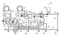
- FIG. 1is a diagrammatic top plan view of a five speed dual clutch automatic transmission incorporating a hydraulic control system according to the present invention
- FIGS. 2A , 2 B, 2 C and 2 Dare a schematic flow diagram of a first embodiment of a hydraulic control system for a dual clutch transmission according to the present invention.
- FIG. 3is a schematic flow diagram of a portion of a second embodiment of a hydraulic control system for a dual clutch transmission according to the present invention.
- the dual clutch transmission 10includes a housing 12 having a plurality of bores, openings, flanges and the like which receive, locate and retain the components of the transmission 10 .
- An input shaft 14is coupled to and driven by a prime mover (not illustrated) such as a gasoline, Diesel, hybrid or electric power plant.
- the input shaft 14is coupled to an input or housing 16 of a dual clutch assembly 18 .
- the dual clutch assembly 18includes a pair of input clutches, a first input clutch 20 and a second input clutch 22 which are commonly driven by the housing 16 .
- the pair of input clutches 20 and 22are controllably engaged or disengaged by a respective pair of hydraulic actuators or operators 24 and 26 .
- the controlled output of the first input clutch 20drives a first drive shaft 28 and the controlled output of the second input clutch 22 drives a second, concentrically disposed quill, drive tube or hollow shaft 30 .
- One of the features and benefits of dual clutch transmissionsis the speed of an adjacent gear shift, e.g., a second gear to third gear upshift.
- Exceedingly rapid shiftsare possible because the gear that is next to be engaged (third, for example) can be preselected or prestaged by synchronizing and connecting it to its countershaft. Actual engagement then involves only opening the input clutch associated with the currently engaged gear (second, for example) and engaging the input clutch associated with the new, desired gear (third). This feature requires that the gears be arranged so that numerically adjacent gears are not driven by the same input clutch.
- first, third and fifth gearsare arranged so that they are driven by one clutch and second, fourth and reverse gears, the even numbered gears, are driven by the other clutch—thereby permitting alternation of the active input clutches as a normal upshift progression through the gears occurs.
- the dual clutch transmission 10is configured to operate in this manner.
- On the first drive shaft 28is a first drive gear 32 and a larger, second drive gear 34 .
- the first drive gear 32 and the second drive gear 34are coupled to and driven by the first drive shaft 28 .
- On the second quill or drive tube 30are a third drive gear 36 and a smaller, fourth drive gear 38 .
- the third drive gear 36 and the fourth drive gear 38are coupled to and driven by the second quill or drive tube 30 .
- a first countershaft or driven shaft 40 Areceives four freely rotating gears which are disposed in two, spaced-apart pairs. Each of the four gears is in constant mesh with one of the drive gears 32 , 34 , 36 or 38 .
- a first large, driven gear 42which provides the largest speed reduction and corresponds to first gear is in constant mesh with the first drive gear 32 on the first drive shaft 28 .
- a second, smallest driven gear 44provides the smallest speed reduction and corresponds to the highest gear, in this case, fifth gear.
- the ratio provided by the second driven gear 44may be 1:1 or the second driven gear 44 may provide overdrive.
- the second driven gear 44is in constant mesh with the second drive gear 34 on the first drive shaft 28 .
- a third, intermediate size driven gear 46provides an intermediate speed ratio which corresponds to fourth gear.
- the third driven gear 46is in constant mesh with the third drive gear 36 on the second quill or drive tube 30 .
- a fourth intermediate size driven gear 48provides another intermediate speed ratio which corresponds to second gear.
- the fourth driven gear 48is in constant mesh with the fourth drive gear 38 on the second quill or drive tube 30 .
- a first output gear 50 Ais coupled to and driven by the first countershaft or driven shaft 40 A.
- a second countershaft or driven shaft 40 Breceives two freely rotating gears which are disposed in a spaced-apart pair. Each of the gears is in constant mesh with a drive gear.
- a fifth, smaller driven gear 52provides another intermediate speed ratio which corresponds to third gear. The fifth driven gear 52 is in constant mesh with the second drive gear 34 on the first drive shaft 28 .
- a sixth, larger driven gear 54provides reverse.
- a reverse idler gear(not illustrated) is in constant mesh with both the sixth driven gear 54 and the fourth drive gear 38 on the second quill or drive tube 30 .
- a second output gear 50 Bis coupled to and driven by the second countershaft or driven shaft 40 B.
- the first output gear 50 A and the second output gear 50 Bmesh with and commonly drive an output gear (not illustrated) which is coupled to and drives an output shaft 62 .
- the output shaft 62drives a final drive assembly (FDA) 64 which may include a prop shaft, transfer case, at least one differential, axles and wheels (all not illustrated).
- FDAfinal drive assembly
- the drive shaft 28 and the drive quill 30 as well as the countershafts 40 A and 40 Bare preferably rotatably supported by pairs of ball bearing assemblies 66 .
- the actual numerical gear ratios provided by the driven gears 42 , 44 , 46 , 48 , 52 and 54are a matter of design choice based upon the actual specifications and desired characteristics of the vehicle and its powertrain.
- the arrangement of the gears 42 , 44 , 46 , 48 , 52 and 54 on the countershafts 40 A and 40 Bis illustrative only and that they may be disposed in other arrangements with the proviso, stated above, that the gears of adjacent gear ratios, i.e., first and second, fourth and fifth, must be configured so that one input clutch provides one gear and the other input clutch provides the adjacent gear ratio.
- the first synchronizer clutch 70Disposed intermediate the fifth driven gear 52 and the reverse gear 54 is a first double synchronizer clutch 70 .
- the first synchronizer clutch 70is slidably coupled to the second countershaft 40 B by a spline set 72 and rotates therewith.
- the first synchronizer clutch 70includes synchronizers and face or dog clutches (not illustrated) which selectively synchronize and then positively couple the fifth driven gear 52 or the reverse gear 54 to the second countershaft 40 B when it is translated to the left or right.
- the first synchronizer clutch 70includes a circumferential channel or groove 74 which is engaged by a second shift fork 76 .
- the second synchronizer clutch 80Disposed intermediate the first driven gear 42 and the second driven gear 44 is a second double synchronizer clutch 80 .
- the second synchronizer clutch 80is slidably coupled to the first countershaft 40 A by a spline set 82 and rotates therewith.
- the second synchronizer clutch 80includes synchronizers and face or dog clutches (not illustrated) which selectively synchronize and then positively couple the first driven gear 42 or the second driven gear 44 to the first countershaft 40 A when it is translated to the left or right, as illustrated in FIG. 1 .
- the second synchronizer clutch 80includes a circumferential channel or groove 84 which is engaged by a first shift fork 86 .
- the third synchronizer clutch 90Disposed intermediate the third driven gear 46 and the fourth driven gear 48 is a third double synchronizer clutch 90 .
- the third synchronizer clutch 90is slidably coupled to the first countershaft 40 A by a spline set 92 and rotates therewith.
- the third synchronizer clutch 90also includes synchronizers and face or dog clutches (not illustrated) which selectively synchronize and then positively couple the third driven gear 46 or the fourth driven gear 48 to the first countershaft 40 A when it is translated to the left or right.
- the third synchronizer clutch 90includes a circumferential channel or groove 94 which is engaged by a third shift fork 96 .
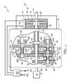
- the hydraulic control system 100includes a common sump 102 which is preferably disposed in the lower portion of the transmission housing 12 .
- a first suction line 104which preferably includes an inlet fiter (not illustrated) communicates between the sump 102 and an inlet or suction port of a first mechanical pump 106 .
- the first mechanical pump 106is preferably a vane, gear or gerotor pump and provides pressurized hydraulic fluid in a first supply line 108 to a clutch cooling circuit.
- the first supply line 108communicates with an inlet port 112 A of a cooler pressure regulator 112 .
- the first supply linealso communicates with a first control port 112 C through a flow restricting orifice 114 and with a pressure relief valve 115 .
- An outlet port 1128 of the cooler pressure regulator 112is connected through a line 116 and an orifice 118 with a hydraulic fluid cooler or heat exchanger 120 through which also passes (in isolation) a heat sink medium.
- the cooler pressure regulator 112also includes a second control port 112 D which is connected through an orifice 124 and a hydraulic line 126 to an outlet port 130 B of a variable force solenoid valve (VFS) 130 .
- the variable force solenoid valve 130also includes an inlet port 130 A and an exhaust port 130 D.
- the hydraulic control system 100also includes a second suction line 138 which communicates between the common sump 102 and an inlet or suction port of a second mechanical pump 140 .
- the second mechanical pump 140is also preferably a vane, gear or gerotor pump and provides pressurized hydraulic fluid in a second supply line 142 to shift logic and clutch control components.
- the second supply line 142communicates with an inlet port 144 A of a pump bypass valve 144 .
- the position of a spool 146 within the bypass valve 144is controlled by an on-off (two position) pump bypass solenoid valve 148 having an inlet port 148 A and an outlet port 148 B which is in fluid communication with a control port of the pump bypass valve 144 .
- the spool 146 of the bypass valve 144When the pump bypass solenoid valve 148 is de-energized, the spool 146 of the bypass valve 144 is in the position illustrated in FIG. 2A and hydraulic fluid in the second supply line 142 is routed along a supply line 150 .
- the pump bypass solenoid valve 148When the pump bypass solenoid valve 148 is energized, the spool 146 of the bypass valve 144 translates to the left in FIG. 2A and hydraulic fluid in the second supply line 142 is routed back to the common sump 102 through a line 152 .
- the supply line 150is in fluid communication with a pressure relief or line blow off valve 154 and a filter 156 which is in fluid parallel with a cold oil bypass valve 158 . Downstream of the filter 156 and the cold oil bypass valve 158 is a pressure retention check valve 160 .
- the pressure retention check valve 160is configured to maintain hydraulic pressure and fluid in a downstream main supply line 162 while permitting fluid flow from the supply line 150 to the main supply line 162 .
- a gas filled or spring accumulator 166 and a main pressure sensor 168are also in fluid communication with the main supply line 162 .
- the main supply line 162communicates with a main manifold 170 having a plurality of ports, outlets or manifold supply lines.
- a first manifold supply line 170 Acommunicates through a filter 172 with an inlet port 174 A of a first (even) clutch variable force (VFS) solenoid valve 174 having an outlet port 174 B which communicates through a filter 176 to a first (even) clutch pressure sensor or switch 178 which detects clutch fill, a cylinder 182 of the first (even) clutch actuator or operator 24 and a logic valve supply line 184 .
- An exhaust port 174 D of the first clutch solenoid valve 174is in fluid communication with a fluid exhaust manifold 190 .
- a second manifold supply line 170 Bcommunicates through a filter 186 with the inlet port 130 A of the variable force solenoid valve 130 .
- a third manifold supply line 170 Ccommunicates through a filter 192 with an inlet port 200 A of a first shift variable force solenoid (VFS) valve 200 .
- the first shift variable force solenoid valve 200includes an outlet port 200 B which is in fluid communication with a filter 202 and a fluid supply line 204 .
- An exhaust port 200 Dis in fluid communication with the fluid exhaust manifold 190 .
- a fourth manifold supply line 170 Dcommunicates with the inlet port 148 A of the on-off (two position) pump bypass solenoid valve 148 .
- a fifth manifold supply line 170 Ecommunicates through a filter 208 with an inlet port 210 A of a second shift variable force solenoid (VFS) valve 210 .
- the second shift variable force solenoid valve 210includes an outlet port 210 B which is in fluid communication with a filter 212 and a fluid supply line 214 .
- An exhaust port 210 Dis in fluid communication with the fluid exhaust manifold 190 .
- a sixth manifold supply line 170 Fcommunicates with an inlet port 220 A of a master logic solenoid valve 220 .
- a seventh manifold supply line 170 Gcommunicates through a filter 228 with an inlet port 230 A of a second (odd) clutch variable force solenoid (VFS) valve 230 having an outlet port 230 B which communicates through a filter 232 to a second (odd) clutch pressure sensor or switch 234 which detects clutch fill, a cylinder 236 of the second clutch actuator or operator 26 and a logic valve supply line 238 .
- An exhaust port 230 D of the second clutch solenoid valve 230is in fluid communication with the fluid exhaust manifold 190 .
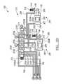
- the master logic solenoid valve 220includes an outlet port 220 B which is in fluid communication with a control port 240 C of a first or master logic spool or control valve 240 .
- the first or master logic valve 240includes a housing 242 having or defining a plurality of inlet and outlet ports and which receives a spool 244 having a plurality of lands which separate and control fluid flows through the housing 242 .
- the master logic solenoid valve 220When the master logic solenoid valve 220 is de-energized or inactive, no pressurized hydraulic fluid is provided to the control port 240 C and the spool 244 resides in the position illustrated in FIG. 2C .
- pressurized hydraulic fluidis provided to the control port 240 C and the spool 244 translates to the left in FIG. 2C .
- the first or master logic spool or control valve 240includes a first inlet port 240 A which is fluid communication with the outlet port 200 B of the first variable flow shift solenoid valve 200 through the line 204 and a second inlet port 240 B which is fluid communication with the outlet port 210 B of the second variable flow shift solenoid valve 210 through the line 214 .
- the first or master logic spool or control valve 240includes a plurality of exhaust ports 240 D, 240 E, 240 F and 240 G which communicate through a branch or extension of the fluid exhaust manifold 190 to the sump 102 .
- the first or master logic spool or control valve 240also includes a first outlet port 240 H which communicates through a line 248 with a port 252 A in a housing or cylinder 252 of a first shift actuator assembly 250 .
- a second port 252 Bcommunicates through a line 254 to a third outlet port 240 J.
- the first shift actuator assembly 250includes a three area piston 256 .
- the three area piston 256is a conventional hydraulic component that, by virtue of its construction, provides three distinct operational positions: a first position at one end or limit of piston travel, a second fixed or defined position generally midway in its travel and a third position at the other end or limit of piston travel.
- the end positions of the piston 256 (and the other three area pistons)typically engage gears whereas the center position is neutral.
- the end positionsare achieved by appropriate application and release of hydraulic fluid on the faces of the pistons whereas the center position is achieved by pressurizing both faces of the pistons equally.
- the first shift actuator assembly 250 and specifically the piston rod 258preferably includes or is connected to a position sensor or position switch (not illustrated) which provides data regarding its current position.
- the three area piston 256is connected to the piston rod 258 which, in turn, is connected to the first shift fork 76 .
- a first detent assembly 262 having a spring biased detenting ball 264 or similar structurecooperates with a detenting recess 78 on the first shift fork 76 and assists obtaining and maintaining a selected position of the shift fork 76 .
- shift actuators having two area pistonswhich lack the defined center position, may be utilized instead of the three area pistons but will require the addition of linear (proportional) position sensors to provide continuous data regarding the position of the piston, piston rod and shift fork.
- hydraulic fluid controlled by the first variable flow shift solenoid valve 200travels through the lines 204 and 248 and translates the three area piston 256 to the right to engage, for example, reverse.
- hydraulic fluid controlled by the second variable flow shift solenoid valve 210travels through the lines 214 and 254 and translates the three area piston 256 to the left to engage, for example, third gear. It will be appreciated that accompanying such operation, and that described below, is the release of hydraulic fluid from the unpressurized side of the cylinder 252 to the fluid exhaust manifold 190 .
- the neutral, center position of the piston 256is achieved by providing pressurized hydraulic fluid through both variable flow shift solenoid valves 200 and 210 and both lines 248 and 254 , as described above.
- the spool 244returns to and resides in the position illustrated in FIG. 2C , as noted above.
- a second outlet port 240 I of the first or master logic spool or control valve 240communicates with a line 266 to a first inlet port 270 A of a second or slave logic spool or control valve 270 and a fourth outlet port 240 K of the first or master logic spool or control valve 240 communicates with a line 268 to a second inlet port 270 B of the second or slave logic valve 270 .
- the second or slave logic valve 270includes a housing 272 having or defining a plurality of inlet and outlet ports and which receives a spool 274 having a plurality of lands which separate and control fluid flows through the housing 272 .
- the second or slave logic valve 270includes a first control port 270 CA which is in fluid communication with the hydraulic line 184 and a second control port 270 CB which is in fluid communication with the hydraulic line 238 . It will thus be appreciated that the position of the spool 274 of the second or slave logic valve 270 is dictated by whether the first (even) input clutch 20 is activated and thus that there is hydraulic pressure in the line 184 or that the second (odd) input clutch 22 is activated and thus that there is hydraulic pressure in the line 238 .
- the second or slave logic valvealso includes a plurality of exhaust ports 270 D, 270 E and 270 F which communicate through the fluid exhaust manifold 190 which flows to the sump 102 .
- the second or slave logic spool or control valve 270also includes a second outlet port 270 I which communicates through a line 276 with a port 282 A in a housing or cylinder 282 of a second shift actuator assembly 280 .
- a second port 282 Bcommunicates through a line 278 to a fourth outlet port 270 K.
- the second shift actuator assembly 280also includes a three area piston 286 .
- the three area piston 286is connected to a second piston rod 288 which, in turn, is connected to the second shift fork 86 .
- a second detent assembly 292 having a spring biased detenting ball 294 or similar structurecooperates with a detenting recess 88 on the second shift fork 86 and assists obtaining and maintaining a selected position of the second shift fork 86 .
- the second or slave logic spool or control valve 270further includes a first outlet port 270 H which communicates through a line 296 with a port 302 A in a housing or cylinder 302 of a third shift actuator assembly 300 .
- a second port 302 Bcommunicates through a line 298 to a third outlet port 270 J.
- the third shift actuator assembly 300also includes a three area piston 306 .
- the three area piston 306is connected to a third piston rod 308 which, in turn, is connected to the third shift fork 96 .
- a third detent assembly 312 having a spring biased detenting ball 314 or similar structurecooperates with a detenting recess 98 on the third shift fork 96 and assists obtaining and maintaining a selected position of the third shift fork 96 .
- the second or slave logic spool or control valve 270includes a clutch cooler inlet port 270 Y which is in fluid communication with the outlet of the hydraulic fluid cooler 120 through a hydraulic line 320 .
- hydraulic fluidflows out an outlet port 270 Z and returns in a line 322 to provide cooling of the first clutch 20 associated with the even numbered gears.
- a flow controlling orifice 326is disposed between the hydraulic line 320 and the line 322 .
- hydraulic fluidflows out an outlet port 270 X and returns in a line 324 to provide cooling of the second clutch 22 associated with the odd numbered gears.
- Another flow controlling orifice 328is disposed between the hydraulic line 320 and the line 324 . In operation, hydraulic fluid from the cooler pressure regulator 112 flows in the line 116 , through the orifice 118 and the cooler 120 .
- the hydraulic fluidflows either through the line 320 to the inlet port 270 Y of the second logic or spool valve 270 which prioritizes fluid flow to either the line 322 and the first clutch 20 or the line 324 and the second clutch 22 or through the orifices 326 and 328 to the respective clutches 20 and 22 .
- first, second, fourth and fifth gearswill now be described with emphasis on the second spool or control valve 270 .
- the second spool or control valve 270When the second spool or control valve 270 is in the de-energized or relaxed position illustrated in FIG. 2D , and the spool 244 of the first spool or control valve 240 is also in its de-energized or relaxed position as illustrated in FIG. 2C , pressurized hydraulic fluid provided through the line 266 and the first inlet port 270 A will be routed to the second outlet port 270 I and through the line 276 and the port 282 A to translate the second piston 286 to the right to engage, for example, fifth gear.
- pressurized hydraulic fluid provided through the line 268 and the second inlet port 270 Bwill be routed to the fourth outlet port 270 K and through the line 278 and the port 282 B to translate the second piston 286 to the left to engage, for example, first gear.
- pressurized hydraulic fluid provided through the line 266 and the first inlet port 270 Awill be routed to the first outlet port 270 H and through the line 296 and the port 302 A to translate the third piston 306 to the right to engage, for example, second gear.
- pressurized hydraulic fluid provided through the line 268 and the second inlet port 270 Bwill be routed to the third outlet port 270 J and through the line 298 and the port 302 B to translate the third piston 306 to the left to engage, for example, fourth gear.
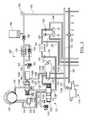
- FIG. 3illustrates a second embodiment of the hydraulic control system 100 of FIGS. 2A through 2D which incorporates an alternate fluid supply configuration.
- the second embodiment hydraulic control system 100 ′includes only a single mechanical pump, the pump 106 , having the suction line 104 which withdraws hydraulic fluid from the sump 102 .
- the mechanical pump 106is, once again, preferably a vane, gear or gerotor pump.
- the outlet or supply line 108communicates with the inlet port 144 A of the pump bypass valve 144 .
- the position of the spool 146 within the bypass valve 144is controlled by the on-off (two position) pump bypass solenoid valve 148 which includes the inlet port 148 A and the outlet port 148 B which is in fluid communication with the control port of the pump bypass valve 144 .
- hydraulic fluid flow from the mechanical pump 106 and the supply line 108is provided to the main supply line 150 and flow, through an outlet port 144 D limited by an orifice 330 , occurs in a line 332 which communicates with the inlet port 112 A of the cooler pressure regulator 112 , the control port 122 C of the cooler pressure regulator 112 through the orifice 114 and the pressure relief valve 115 .
- the orifice 330always provides minimal hydraulic fluid flow and cooling to the clutches 20 and 22 .
- the components and operation of the remainder of the second embodiment control system 100 ′are the same as the first embodiment and include the cooler 120 , the main manifold 170 , the first clutch solenoid valve 174 , the first shift solenoid valve 200 , the second shift solenoid valve 210 , the second clutch solenoid valve 230 , the master logic solenoid valve 220 , the first logic or spool valve 240 , the second logic or spool valve 270 , the shift actuator assemblies 250 , 280 and 300 and the associated hydraulic lines and filters.
- the foregoing embodiments of the invention having the accumulator 166 , the pump bypass valve 144 , and the engine driven pump 106 or pumps 106 and 140provide operational efficiency much greater than a hydraulic control system without the accumulator.
- the incorporation of the accumulator 166allows downsizing of the pump, and improved engine start-stop capability.
- the hydraulic control systems 100 and 100 ′have essentially minimum content to control a wet dual clutch transmission such as the transmission 10 and are thus an efficient control system design.
Landscapes
- Engineering & Computer Science (AREA)
- General Engineering & Computer Science (AREA)
- Mechanical Engineering (AREA)
- Control Of Transmission Device (AREA)
- Hydraulic Clutches, Magnetic Clutches, Fluid Clutches, And Fluid Joints (AREA)
Abstract
Description
Claims (14)
Priority Applications (3)
| Application Number | Priority Date | Filing Date | Title |
|---|---|---|---|
| US12/707,414US8413777B2 (en) | 2010-02-17 | 2010-02-17 | High efficiency hydraulic transmission control system |
| DE102011010749ADE102011010749A1 (en) | 2010-02-17 | 2011-02-09 | Highly efficient hydraulic transmission control system |
| CN201110041240.2ACN102162522B (en) | 2010-02-17 | 2011-02-17 | High efficiency hydraulic transmission control system |
Applications Claiming Priority (1)
| Application Number | Priority Date | Filing Date | Title |
|---|---|---|---|
| US12/707,414US8413777B2 (en) | 2010-02-17 | 2010-02-17 | High efficiency hydraulic transmission control system |
Publications (2)
| Publication Number | Publication Date |
|---|---|
| US20110198178A1 US20110198178A1 (en) | 2011-08-18 |
| US8413777B2true US8413777B2 (en) | 2013-04-09 |
Family
ID=44368870
Family Applications (1)
| Application Number | Title | Priority Date | Filing Date |
|---|---|---|---|
| US12/707,414Expired - Fee RelatedUS8413777B2 (en) | 2010-02-17 | 2010-02-17 | High efficiency hydraulic transmission control system |
Country Status (3)
| Country | Link |
|---|---|
| US (1) | US8413777B2 (en) |
| CN (1) | CN102162522B (en) |
| DE (1) | DE102011010749A1 (en) |
Cited By (7)
| Publication number | Priority date | Publication date | Assignee | Title |
|---|---|---|---|---|
| US20120137806A1 (en)* | 2010-12-06 | 2012-06-07 | GM Global Technology Operations LLC | Method of controlling a dual clutch transmission |
| US20140208882A1 (en)* | 2013-01-30 | 2014-07-31 | C.R.F. Societa Consortile Per Azioni | Gearbox for a motor vehicle |
| US20150128737A1 (en)* | 2013-11-08 | 2015-05-14 | Honda Motor Co., Ltd. | Shift actuator |
| US10563759B1 (en)* | 2018-07-30 | 2020-02-18 | Hyundai Motor Company | Hydraulic control apparatus of shift control unit for dual clutch transmission |
| US10718426B2 (en) | 2017-06-30 | 2020-07-21 | Allison Transmission, Inc. | Control system and method thereof for multispeed transmission |
| US10753464B2 (en) | 2016-06-21 | 2020-08-25 | Borgwarner Inc. | Switch valve assembly and hydraulic control module including same |
| US11181193B2 (en) | 2019-11-27 | 2021-11-23 | Allison Transmission, Inc. | Power off hydraulic default strategy |
Families Citing this family (11)
| Publication number | Priority date | Publication date | Assignee | Title |
|---|---|---|---|---|
| US8234946B2 (en)* | 2010-02-17 | 2012-08-07 | GM Global Technology Operations LLC | Hydraulic control system for a dual clutch transmission |
| US8678780B2 (en)* | 2010-02-26 | 2014-03-25 | GM Global Technology Operations LLC | Transmission hydraulic control system having a pump bypass valve |
| US8430220B2 (en)* | 2010-06-04 | 2013-04-30 | GM Global Technology Operations LLC | Wet dual clutch transmission control system |
| CN101975270B (en)* | 2010-11-04 | 2013-09-25 | 大久(天津)科技有限公司 | Electronic control hydraulic automatic gear shifting system |
| JP5762551B2 (en)* | 2011-10-07 | 2015-08-12 | ヤマハ発動機株式会社 | Vehicle control device, vehicle and prime mover |
| US9163720B2 (en)* | 2011-11-14 | 2015-10-20 | Gm Global Technology Operations, Llc | Transmission hydraulic control system having an automatic engine stop-start accumulator |
| US9016454B2 (en)* | 2011-12-23 | 2015-04-28 | Schaeffler Technologies AG & Co., KG | Two stage piston for faster clutch apply |
| US8734293B1 (en) | 2012-12-06 | 2014-05-27 | Ford Global Technologies, Llc | Accumulator for maintaining hydraulic pressure following an engine restart |
| US9574654B2 (en)* | 2013-06-05 | 2017-02-21 | Gm Global Technology Operations, Llc | Hydraulic control system with ETRS for a continuously variable transmission |
| CN105626844A (en)* | 2014-10-28 | 2016-06-01 | 上海汽车集团股份有限公司 | Hydraulic control system of wet type double-clutch speed changing box |
| FR3057331B1 (en)* | 2016-10-11 | 2018-11-09 | Peugeot Citroen Automobiles Sa | METHOD AND DEVICE FOR LEARNING STARTING POSITIONS OF CRABOTAGE OF ACTUATORS OF A DCT GEARBOX OF A VEHICLE |
Citations (61)
| Publication number | Priority date | Publication date | Assignee | Title |
|---|---|---|---|---|
| DE2141564A1 (en) | 1971-08-19 | 1973-02-22 | Zahnradfabrik Friedrichshafen | SUB CIRCUIT IN A HYDRAULIC ENGINE AND CLUTCH CONTROL FOR VEHICLE DRIVES |
| US3834499A (en) | 1971-09-25 | 1974-09-10 | Fiat Spa | Clutch, brake and motor controls for synchronized gear shifting |
| JPS58102851A (en) | 1981-12-11 | 1983-06-18 | Mazda Motor Corp | Composite clutch type multistage change gear |
| US4653352A (en) | 1984-02-20 | 1987-03-31 | Aisin Seiki Kabushiki Kaisha | Automatic transmission system for automobiles having hydraulic and electronic control systems |
| US4944202A (en) | 1986-09-09 | 1990-07-31 | Zahnradfabrik Friedrichshafen Ag | Electrohydraulic control for an automatically shiftable automotive transmission |
| EP0477564A2 (en) | 1990-08-31 | 1992-04-01 | Isuzu Motors Limited | Electronically controlled transmission |
| DE4117736C1 (en) | 1991-05-30 | 1992-05-21 | Mercedes-Benz Aktiengesellschaft, 7000 Stuttgart, De | |
| DE4320353A1 (en) | 1992-06-27 | 1994-01-05 | Teves Gmbh Alfred | Hydraulic gearshift control for motor vehicle - has two separate slave cylinders to operate gear selector and one clutch slave cylinder |
| US5441459A (en) | 1992-12-28 | 1995-08-15 | Mitsubishi Jidosha Kogyo Kaubshiki Kaisha | Hydraulic control appartus for automatic transmission |
| WO1997005410A1 (en) | 1995-07-26 | 1997-02-13 | Ap Kongsberg Holdings Limited | Ratio selector mechanisms |
| DE29714652U1 (en) | 1997-05-15 | 1997-10-09 | Mannesmann Sachs Ag | Actuator with valve units for actuating a friction clutch and an automated gearbox |
| WO1999019644A1 (en) | 1997-10-10 | 1999-04-22 | Renault | Method and device for controlling the supply of an automatic transmission hydraulic actuators |
| DE19921301A1 (en) | 1998-05-20 | 1999-11-25 | Luk Getriebe Systeme Gmbh | Hydraulic control system for motor vehicles |
| DE19849488A1 (en) | 1998-10-27 | 2000-05-11 | Mannesmann Sachs Ag | Hydraulic actuation device for an automated manual transmission with reduced leakage or / under with actuator cylinder counterhold |
| DE19931973A1 (en) | 1999-07-09 | 2001-01-11 | Wabco Gmbh & Co Ohg | Device for controlling an actuator for a transmission |
| FR2808065A1 (en) | 2000-04-21 | 2001-10-26 | Renault | Hydraulically controlled transmission for motor vehicles, uses controlled solenoid valves to selectively connect pressure source to engine coupling clutch or gear engagement clutches |
| US20010036878A1 (en) | 2000-03-29 | 2001-11-01 | Aisin Aw Co., Ltd. | Hydraulic control apparatus for automatic transmission |
| US20020060113A1 (en) | 2000-11-21 | 2002-05-23 | Luk Lamellen Und Kupplungsbau Beteiligungs Kg | Hydraulic actuation systems |
| US20020119854A1 (en) | 2000-12-21 | 2002-08-29 | Mohr John Alan | Power transmission drive system |
| DE10125172A1 (en) | 2001-05-23 | 2002-11-28 | Volkswagen Ag | Hydraulic switching control device for a multispeed gear change box, especially a double clutch gear box, comprises a multi-way switching valve arranged between control valves and switching elements |
| DE10134115A1 (en) | 2001-07-13 | 2003-01-23 | Volkswagen Ag | Hydraulic circuit for controlling dual clutch gearbox, especially for motor vehicle, has central distributing valve device between switching cylinders and pressure valves |
| US20030075408A1 (en) | 1999-12-13 | 2003-04-24 | Sverker Alfredsson | Hydraulic regulating system for a vehicle transmission |
| US20030226416A1 (en) | 2002-04-18 | 2003-12-11 | Kubota Corporation | Control apparatus for transmission |
| US20040038765A1 (en) | 2002-06-28 | 2004-02-26 | Takuya Fujimine | Hydraulic control system for automatic transmission |
| US6698304B2 (en) | 2001-10-17 | 2004-03-02 | Zf Friedrichshafen Ag | Method for controlling a dual clutch transmission |
| EP1400733A2 (en) | 2002-09-18 | 2004-03-24 | Volkswagen Aktiengesellschaft | Hydraulic control apparatus of a double clutch gearbox |
| US6715597B1 (en) | 2002-10-25 | 2004-04-06 | Borgwarner, Inc. | Dual clutch transmission clutch cooling control method |
| EP1433976A1 (en) | 2002-12-23 | 2004-06-30 | Renault s.a.s. | Control device for a transmission |
| US6789658B2 (en) | 2001-09-07 | 2004-09-14 | Zf Sachs Ag | Clutch system |
| EP1469235A1 (en) | 2003-04-17 | 2004-10-20 | BorgWarner, Inc. | Hydraulic control and regulating system and method for adjusting the hydraulic pressure levels |
| WO2004097264A1 (en) | 2003-05-01 | 2004-11-11 | GOVERS, Henricus, Johannes, Antonius, Alphonsus | Road vehicle with auxiliary installation |
| US6827191B2 (en) | 2001-12-21 | 2004-12-07 | Zf Sachs Ag | Clutch system with at least one multiple-plate clutch arrangement |
| EP1519082A1 (en) | 2003-09-29 | 2005-03-30 | BorgWarner, Inc. | Control device and method for hydraulically operated clutches |
| US20050067251A1 (en) | 2003-09-30 | 2005-03-31 | Borg Warner, Inc. | Oil management system for dual clutch transmissions |
| US6883394B2 (en) | 2002-10-15 | 2005-04-26 | Borgwarner, Inc. | Method for controlling the positioning of the synchronizers of a dual clutch transmission |
| US20050107214A1 (en) | 2003-11-17 | 2005-05-19 | Melissa Koenig | Method for controlling a dual clutch transmission |
| US6941830B2 (en) | 2000-03-10 | 2005-09-13 | Hitachi, Ltd. | Automatic transmission, dynamo-electric machine, and car |
| EP1589262A1 (en) | 2004-04-22 | 2005-10-26 | Borg Warner Inc. | Hydraulic control unit for a dual clutch transmission and method of hydraulic control of such a transmission |
| EP1645786A2 (en) | 2004-10-08 | 2006-04-12 | Audi Ag | Hydraulic control apparatus and method for a gearbox with clutch |
| JP2007010145A (en) | 2005-06-28 | 2007-01-18 | Volkswagen Ag <Vw> | Hydraulic circuit for automobile transmission |
| DE102005029963A1 (en) | 2005-06-28 | 2007-02-15 | Volkswagen Ag | Hydraulic circuit e.g. high pressure hydraulic circuit, for e.g. dual-coupling gear box of motor vehicle, has partial high-pressure hydraulic circuits with pressure sensors and pressure accumulators and connected upstream of safety valves |
| EP1767824A1 (en) | 2005-09-22 | 2007-03-28 | Getrag Ford Transmissions GmbH | Hydraulic controller for an automated double clutch gearbox |
| US20070175726A1 (en) | 2004-06-03 | 2007-08-02 | Peugeot Citroen Automobiles Sa | Hydraulic clutch transmission element for a hybrid traction chain of a motor vechicle, and motor vehicle comprising one such element |
| US7300375B2 (en) | 2003-04-30 | 2007-11-27 | Getrag Getriebe-Und Zahnradfabrik Hermann Hagenmeyer Gmbh & Cie Kg | Hydraulic circuit for the control of a drive train |
| US7401689B2 (en) | 2004-09-16 | 2008-07-22 | Getrag Ford Transmissions Gmbh | Hydraulic system providing pressure and volume flows in a double-clutch transmission |
| US20080207392A1 (en) | 2007-02-12 | 2008-08-28 | Luk Lamellen Und Kupplungsbau Beteiligungs Kg | Device for actuating a plurality of hydraulic control cylinders |
| US20080210032A1 (en) | 2007-03-01 | 2008-09-04 | C,R,F, Societa Consortile Per Aziono | Electro-hydraulic control system for a motor-vehicle dual-clutch transmission |
| DE102008008454A1 (en) | 2007-03-07 | 2008-09-11 | Luk Lamellen Und Kupplungsbau Beteiligungs Kg | Hydraulic system for controlling a wet clutch dual clutch transmission |
| US7464618B2 (en) | 2004-09-02 | 2008-12-16 | Getrag Ford Transmissions Gmbh | Hydraulic control apparatus for an automatic dual clutch transmission |
| US7464617B2 (en) | 2004-07-09 | 2008-12-16 | Crf Societa Consortile Per Azioni | Servo-assisted control system for the gears of a double clutch gearbox of a motor vehicle |
| US20090000897A1 (en) | 2006-03-08 | 2009-01-01 | Luk Lamellen Und Kupplungsbau Beteiligungs Kg | Hydraulic control for a dual clutch transmission |
| US7472616B2 (en) | 2005-01-25 | 2009-01-06 | Getrag Getriebe- Und Zahnradfabrik Hermann Hagenmeyer Gmbh & Cie Kg | Step-by-step variable transmission and method for controlling the same |
| US7478572B2 (en) | 2006-02-27 | 2009-01-20 | Gm Global Technology Operations, Inc. | Transmission with torque sensors and method of controlling a transmission |
| WO2009037170A1 (en) | 2007-09-18 | 2009-03-26 | Zf Friedrichshafen Ag | Electrohydraulic control device |
| US20090157271A1 (en) | 2007-12-18 | 2009-06-18 | C.R.F. Societa' Consortile Per Azioni | Electro-hydraulic control apparatus for a motor vehicle transmission with at least five forward gears and one reverse gear |
| US20090151495A1 (en) | 2007-12-18 | 2009-06-18 | C.R.F. Societa' Consortile Per Azioni | Electro-hydraulic control apparatus for a motor-vehicle transmission with at least five forward gears and one reverse gear |
| DE102008058692A1 (en) | 2007-12-06 | 2009-06-18 | Luk Lamellen Und Kupplungsbau Beteiligungs Kg | Hydraulic arrangement for controlling e.g. double clutch gear, of motor vehicle, has hydraulic energy sources for generating system pressure downstream to valve, and regulating circuit for regulating clutch pressure |
| US7591203B2 (en) | 2006-02-28 | 2009-09-22 | Hitachi, Ltd. | Control apparatus and control method for vehicle |
| EP2151586A2 (en) | 2008-08-09 | 2010-02-10 | Volkswagen Aktiengesellschaft | Hydraulic circuit |
| WO2010028745A2 (en) | 2008-09-09 | 2010-03-18 | Volkswagen Aktiengesellschaft | Method and hydraulic circuit for the hydraulic control of a motor vehicle transmission, particularly an automatic or automatized motor vehicle transmission |
| US20110297499A1 (en)* | 2010-06-04 | 2011-12-08 | Gm Global Technology Operations, Inc. | Wet dual clutch transmission control system |
Family Cites Families (2)
| Publication number | Priority date | Publication date | Assignee | Title |
|---|---|---|---|---|
| GB2372080B (en)* | 2001-02-12 | 2004-09-29 | Luk Lamellen & Kupplungsbau | Hydraulic actuation systems |
| US7752935B2 (en)* | 2007-03-08 | 2010-07-13 | Gm Global Technology Operations, Inc. | Control system for a multi-speed transmission |
- 2010
- 2010-02-17USUS12/707,414patent/US8413777B2/ennot_activeExpired - Fee Related
- 2011
- 2011-02-09DEDE102011010749Apatent/DE102011010749A1/ennot_activeWithdrawn
- 2011-02-17CNCN201110041240.2Apatent/CN102162522B/ennot_activeExpired - Fee Related
Patent Citations (66)
| Publication number | Priority date | Publication date | Assignee | Title |
|---|---|---|---|---|
| DE2141564A1 (en) | 1971-08-19 | 1973-02-22 | Zahnradfabrik Friedrichshafen | SUB CIRCUIT IN A HYDRAULIC ENGINE AND CLUTCH CONTROL FOR VEHICLE DRIVES |
| US3834499A (en) | 1971-09-25 | 1974-09-10 | Fiat Spa | Clutch, brake and motor controls for synchronized gear shifting |
| JPS58102851A (en) | 1981-12-11 | 1983-06-18 | Mazda Motor Corp | Composite clutch type multistage change gear |
| US4653352A (en) | 1984-02-20 | 1987-03-31 | Aisin Seiki Kabushiki Kaisha | Automatic transmission system for automobiles having hydraulic and electronic control systems |
| US4944202A (en) | 1986-09-09 | 1990-07-31 | Zahnradfabrik Friedrichshafen Ag | Electrohydraulic control for an automatically shiftable automotive transmission |
| EP0477564A2 (en) | 1990-08-31 | 1992-04-01 | Isuzu Motors Limited | Electronically controlled transmission |
| DE4117736C1 (en) | 1991-05-30 | 1992-05-21 | Mercedes-Benz Aktiengesellschaft, 7000 Stuttgart, De | |
| US5240093A (en)* | 1991-05-30 | 1993-08-31 | Mercedes-Benz Ag | Configuration for the pressure supply to an automatic selector device of a change-speed gearbox |
| DE4320353A1 (en) | 1992-06-27 | 1994-01-05 | Teves Gmbh Alfred | Hydraulic gearshift control for motor vehicle - has two separate slave cylinders to operate gear selector and one clutch slave cylinder |
| US5441459A (en) | 1992-12-28 | 1995-08-15 | Mitsubishi Jidosha Kogyo Kaubshiki Kaisha | Hydraulic control appartus for automatic transmission |
| WO1997005410A1 (en) | 1995-07-26 | 1997-02-13 | Ap Kongsberg Holdings Limited | Ratio selector mechanisms |
| DE29714652U1 (en) | 1997-05-15 | 1997-10-09 | Mannesmann Sachs Ag | Actuator with valve units for actuating a friction clutch and an automated gearbox |
| WO1999019644A1 (en) | 1997-10-10 | 1999-04-22 | Renault | Method and device for controlling the supply of an automatic transmission hydraulic actuators |
| DE19921301A1 (en) | 1998-05-20 | 1999-11-25 | Luk Getriebe Systeme Gmbh | Hydraulic control system for motor vehicles |
| DE19849488A1 (en) | 1998-10-27 | 2000-05-11 | Mannesmann Sachs Ag | Hydraulic actuation device for an automated manual transmission with reduced leakage or / under with actuator cylinder counterhold |
| DE19931973A1 (en) | 1999-07-09 | 2001-01-11 | Wabco Gmbh & Co Ohg | Device for controlling an actuator for a transmission |
| US20030075408A1 (en) | 1999-12-13 | 2003-04-24 | Sverker Alfredsson | Hydraulic regulating system for a vehicle transmission |
| US6941830B2 (en) | 2000-03-10 | 2005-09-13 | Hitachi, Ltd. | Automatic transmission, dynamo-electric machine, and car |
| US20010036878A1 (en) | 2000-03-29 | 2001-11-01 | Aisin Aw Co., Ltd. | Hydraulic control apparatus for automatic transmission |
| FR2808065A1 (en) | 2000-04-21 | 2001-10-26 | Renault | Hydraulically controlled transmission for motor vehicles, uses controlled solenoid valves to selectively connect pressure source to engine coupling clutch or gear engagement clutches |
| US20020060113A1 (en) | 2000-11-21 | 2002-05-23 | Luk Lamellen Und Kupplungsbau Beteiligungs Kg | Hydraulic actuation systems |
| US20020119854A1 (en) | 2000-12-21 | 2002-08-29 | Mohr John Alan | Power transmission drive system |
| DE10125172A1 (en) | 2001-05-23 | 2002-11-28 | Volkswagen Ag | Hydraulic switching control device for a multispeed gear change box, especially a double clutch gear box, comprises a multi-way switching valve arranged between control valves and switching elements |
| DE10134115A1 (en) | 2001-07-13 | 2003-01-23 | Volkswagen Ag | Hydraulic circuit for controlling dual clutch gearbox, especially for motor vehicle, has central distributing valve device between switching cylinders and pressure valves |
| US6789658B2 (en) | 2001-09-07 | 2004-09-14 | Zf Sachs Ag | Clutch system |
| US6698304B2 (en) | 2001-10-17 | 2004-03-02 | Zf Friedrichshafen Ag | Method for controlling a dual clutch transmission |
| US6827191B2 (en) | 2001-12-21 | 2004-12-07 | Zf Sachs Ag | Clutch system with at least one multiple-plate clutch arrangement |
| US20030226416A1 (en) | 2002-04-18 | 2003-12-11 | Kubota Corporation | Control apparatus for transmission |
| US20040038765A1 (en) | 2002-06-28 | 2004-02-26 | Takuya Fujimine | Hydraulic control system for automatic transmission |
| EP1400733A2 (en) | 2002-09-18 | 2004-03-24 | Volkswagen Aktiengesellschaft | Hydraulic control apparatus of a double clutch gearbox |
| DE10243282A1 (en) | 2002-09-18 | 2004-04-01 | Volkswagen Ag | Hydraulic control device of a dual-clutch transmission |
| US6883394B2 (en) | 2002-10-15 | 2005-04-26 | Borgwarner, Inc. | Method for controlling the positioning of the synchronizers of a dual clutch transmission |
| US6715597B1 (en) | 2002-10-25 | 2004-04-06 | Borgwarner, Inc. | Dual clutch transmission clutch cooling control method |
| EP1433976A1 (en) | 2002-12-23 | 2004-06-30 | Renault s.a.s. | Control device for a transmission |
| EP1469235A1 (en) | 2003-04-17 | 2004-10-20 | BorgWarner, Inc. | Hydraulic control and regulating system and method for adjusting the hydraulic pressure levels |
| US7300375B2 (en) | 2003-04-30 | 2007-11-27 | Getrag Getriebe-Und Zahnradfabrik Hermann Hagenmeyer Gmbh & Cie Kg | Hydraulic circuit for the control of a drive train |
| WO2004097264A1 (en) | 2003-05-01 | 2004-11-11 | GOVERS, Henricus, Johannes, Antonius, Alphonsus | Road vehicle with auxiliary installation |
| EP1519082A1 (en) | 2003-09-29 | 2005-03-30 | BorgWarner, Inc. | Control device and method for hydraulically operated clutches |
| US20050067251A1 (en) | 2003-09-30 | 2005-03-31 | Borg Warner, Inc. | Oil management system for dual clutch transmissions |
| US20050107214A1 (en) | 2003-11-17 | 2005-05-19 | Melissa Koenig | Method for controlling a dual clutch transmission |
| EP1589262A1 (en) | 2004-04-22 | 2005-10-26 | Borg Warner Inc. | Hydraulic control unit for a dual clutch transmission and method of hydraulic control of such a transmission |
| US20070175726A1 (en) | 2004-06-03 | 2007-08-02 | Peugeot Citroen Automobiles Sa | Hydraulic clutch transmission element for a hybrid traction chain of a motor vechicle, and motor vehicle comprising one such element |
| US7464617B2 (en) | 2004-07-09 | 2008-12-16 | Crf Societa Consortile Per Azioni | Servo-assisted control system for the gears of a double clutch gearbox of a motor vehicle |
| US7464618B2 (en) | 2004-09-02 | 2008-12-16 | Getrag Ford Transmissions Gmbh | Hydraulic control apparatus for an automatic dual clutch transmission |
| US7401689B2 (en) | 2004-09-16 | 2008-07-22 | Getrag Ford Transmissions Gmbh | Hydraulic system providing pressure and volume flows in a double-clutch transmission |
| EP1645786A2 (en) | 2004-10-08 | 2006-04-12 | Audi Ag | Hydraulic control apparatus and method for a gearbox with clutch |
| US7472616B2 (en) | 2005-01-25 | 2009-01-06 | Getrag Getriebe- Und Zahnradfabrik Hermann Hagenmeyer Gmbh & Cie Kg | Step-by-step variable transmission and method for controlling the same |
| DE102005029964A1 (en) | 2005-06-28 | 2007-03-22 | Volkswagen Ag | Hydraulic circuit for a transmission of a motor vehicle |
| DE102005029963A1 (en) | 2005-06-28 | 2007-02-15 | Volkswagen Ag | Hydraulic circuit e.g. high pressure hydraulic circuit, for e.g. dual-coupling gear box of motor vehicle, has partial high-pressure hydraulic circuits with pressure sensors and pressure accumulators and connected upstream of safety valves |
| US7487866B2 (en) | 2005-06-28 | 2009-02-10 | Volkswagen Ag | Hydraulic circuit for a transmission of a motor vehicle |
| JP2007010145A (en) | 2005-06-28 | 2007-01-18 | Volkswagen Ag <Vw> | Hydraulic circuit for automobile transmission |
| EP1767824A1 (en) | 2005-09-22 | 2007-03-28 | Getrag Ford Transmissions GmbH | Hydraulic controller for an automated double clutch gearbox |
| US7478572B2 (en) | 2006-02-27 | 2009-01-20 | Gm Global Technology Operations, Inc. | Transmission with torque sensors and method of controlling a transmission |
| US7591203B2 (en) | 2006-02-28 | 2009-09-22 | Hitachi, Ltd. | Control apparatus and control method for vehicle |
| US20090000897A1 (en) | 2006-03-08 | 2009-01-01 | Luk Lamellen Und Kupplungsbau Beteiligungs Kg | Hydraulic control for a dual clutch transmission |
| US20080207392A1 (en) | 2007-02-12 | 2008-08-28 | Luk Lamellen Und Kupplungsbau Beteiligungs Kg | Device for actuating a plurality of hydraulic control cylinders |
| US20080210032A1 (en) | 2007-03-01 | 2008-09-04 | C,R,F, Societa Consortile Per Aziono | Electro-hydraulic control system for a motor-vehicle dual-clutch transmission |
| US20080223683A1 (en) | 2007-03-07 | 2008-09-18 | Luk Lamellen Und Kupplungsbau Beteiligungs Kg | Hydraulic system for controlling a double-clutch transmission |
| DE102008008454A1 (en) | 2007-03-07 | 2008-09-11 | Luk Lamellen Und Kupplungsbau Beteiligungs Kg | Hydraulic system for controlling a wet clutch dual clutch transmission |
| WO2009037170A1 (en) | 2007-09-18 | 2009-03-26 | Zf Friedrichshafen Ag | Electrohydraulic control device |
| DE102008058692A1 (en) | 2007-12-06 | 2009-06-18 | Luk Lamellen Und Kupplungsbau Beteiligungs Kg | Hydraulic arrangement for controlling e.g. double clutch gear, of motor vehicle, has hydraulic energy sources for generating system pressure downstream to valve, and regulating circuit for regulating clutch pressure |
| US20090157271A1 (en) | 2007-12-18 | 2009-06-18 | C.R.F. Societa' Consortile Per Azioni | Electro-hydraulic control apparatus for a motor vehicle transmission with at least five forward gears and one reverse gear |
| US20090151495A1 (en) | 2007-12-18 | 2009-06-18 | C.R.F. Societa' Consortile Per Azioni | Electro-hydraulic control apparatus for a motor-vehicle transmission with at least five forward gears and one reverse gear |
| EP2151586A2 (en) | 2008-08-09 | 2010-02-10 | Volkswagen Aktiengesellschaft | Hydraulic circuit |
| WO2010028745A2 (en) | 2008-09-09 | 2010-03-18 | Volkswagen Aktiengesellschaft | Method and hydraulic circuit for the hydraulic control of a motor vehicle transmission, particularly an automatic or automatized motor vehicle transmission |
| US20110297499A1 (en)* | 2010-06-04 | 2011-12-08 | Gm Global Technology Operations, Inc. | Wet dual clutch transmission control system |
Cited By (15)
| Publication number | Priority date | Publication date | Assignee | Title |
|---|---|---|---|---|
| US8904893B2 (en)* | 2010-12-06 | 2014-12-09 | Gm Global Technology Operations, Llc | Method of controlling a dual clutch transmission |
| US20120137806A1 (en)* | 2010-12-06 | 2012-06-07 | GM Global Technology Operations LLC | Method of controlling a dual clutch transmission |
| US20140208882A1 (en)* | 2013-01-30 | 2014-07-31 | C.R.F. Societa Consortile Per Azioni | Gearbox for a motor vehicle |
| US9458921B2 (en)* | 2013-01-30 | 2016-10-04 | C.R.F. Societa Consortile Per Azioni | Gearbox for a motor vehicle |
| US20150128737A1 (en)* | 2013-11-08 | 2015-05-14 | Honda Motor Co., Ltd. | Shift actuator |
| US9435401B2 (en)* | 2013-11-08 | 2016-09-06 | Honda Motor Co., Ltd. | Shift actuator |
| US10753464B2 (en) | 2016-06-21 | 2020-08-25 | Borgwarner Inc. | Switch valve assembly and hydraulic control module including same |
| US10830341B2 (en) | 2017-06-30 | 2020-11-10 | Allison Transmission, Inc. | Control system and method thereof for multispeed transmission |
| US10718426B2 (en) | 2017-06-30 | 2020-07-21 | Allison Transmission, Inc. | Control system and method thereof for multispeed transmission |
| US10920875B2 (en) | 2017-06-30 | 2021-02-16 | Allison Transmission, Inc. | Control system and method thereof for multispeed transmission |
| US11047474B2 (en) | 2017-06-30 | 2021-06-29 | Allison Transmission, Inc. | Control system and method thereof for multispeed transmission |
| US11725724B2 (en) | 2017-06-30 | 2023-08-15 | Allison Transmission, Inc. | Control system and method thereof for multispeed transmission |
| US12173788B2 (en) | 2017-06-30 | 2024-12-24 | Allison Transmission, Inc. | Control system and method thereof for multispeed transmission |
| US10563759B1 (en)* | 2018-07-30 | 2020-02-18 | Hyundai Motor Company | Hydraulic control apparatus of shift control unit for dual clutch transmission |
| US11181193B2 (en) | 2019-11-27 | 2021-11-23 | Allison Transmission, Inc. | Power off hydraulic default strategy |
Also Published As
| Publication number | Publication date |
|---|---|
| DE102011010749A1 (en) | 2012-03-01 |
| US20110198178A1 (en) | 2011-08-18 |
| CN102162522A (en) | 2011-08-24 |
| CN102162522B (en) | 2014-09-03 |
Similar Documents
| Publication | Publication Date | Title |
|---|---|---|
| US8413777B2 (en) | High efficiency hydraulic transmission control system | |
| US8402855B2 (en) | Hydraulic control systems for dual clutch transmissions | |
| US8430220B2 (en) | Wet dual clutch transmission control system | |
| US8206265B2 (en) | Control system for dual clutch transmission | |
| US8429994B2 (en) | Hydraulic control systems for dual clutch transmissions | |
| US8225687B2 (en) | Hydraulic control systems for dual clutch transmissions | |
| US7752935B2 (en) | Control system for a multi-speed transmission | |
| US6631651B2 (en) | Hydraulic circuit for an automated twin clutch transmission for motor vehicles | |
| US8359941B2 (en) | Hydraulic control systems for dual clutch transmissions | |
| JP5216785B2 (en) | Hydraulically operated valve device for dual clutch transmission | |
| US8403792B2 (en) | Hydraulic control systems for dual clutch transmissions | |
| US8443687B2 (en) | Electro-hydraulic control system for a dual clutch transmission | |
| US8567580B2 (en) | Electro-hydraulic control system for a dual clutch transmission | |
| US8356529B2 (en) | Hydraulic control systems for dual clutch transmissions | |
| US8528711B2 (en) | Control system for a dual clutch transmission | |
| US8382639B2 (en) | Control system for a dual clutch transmission | |
| US20110028271A1 (en) | Hydraulic control system for a dual clutch transmission | |
| US8839928B2 (en) | Electro-hydraulic control system for a dual clutch transmission | |
| US8434603B2 (en) | Low content control system for a dual clutch transmission | |
| KR20110131195A (en) | Electro-hydraulic fault recovery control for dual clutch transmission | |
| US8820185B2 (en) | Control system for a dual clutch transmission | |
| US8402993B2 (en) | Hydraulic fluid cooling system for a dual clutch automatic transmission | |
| US8192176B2 (en) | Hydraulic fluid supply system having active regulator | |
| US8590684B2 (en) | Control system for a dual clutch transmission |
Legal Events
| Date | Code | Title | Description |
|---|---|---|---|
| AS | Assignment | Owner name:GM GLOBAL TECHNOLOGY OPERATIONS, INC., MICHIGAN Free format text:ASSIGNMENT OF ASSIGNORS INTEREST;ASSIGNORS:LUNDBERG, PHILIP C.;DOUGAN, KEVIN MICHAEL;OLSON, BRET M.;SIGNING DATES FROM 20100126 TO 20100210;REEL/FRAME:023952/0935 | |
| AS | Assignment | Owner name:WILMINGTON TRUST COMPANY, DELAWARE Free format text:SECURITY AGREEMENT;ASSIGNOR:GM GLOBAL TECHNOLOGY OPERATIONS, INC.;REEL/FRAME:025327/0156 Effective date:20101027 | |
| AS | Assignment | Owner name:GM GLOBAL TECHNOLOGY OPERATIONS LLC, MICHIGAN Free format text:CHANGE OF NAME;ASSIGNOR:GM GLOBAL TECHNOLOGY OPERATIONS, INC.;REEL/FRAME:025781/0333 Effective date:20101202 | |
| FEPP | Fee payment procedure | Free format text:PAYOR NUMBER ASSIGNED (ORIGINAL EVENT CODE: ASPN); ENTITY STATUS OF PATENT OWNER: LARGE ENTITY | |
| STCF | Information on status: patent grant | Free format text:PATENTED CASE | |
| AS | Assignment | Owner name:GM GLOBAL TECHNOLOGY OPERATIONS LLC, MICHIGAN Free format text:RELEASE BY SECURED PARTY;ASSIGNOR:WILMINGTON TRUST COMPANY;REEL/FRAME:034287/0001 Effective date:20141017 | |
| FPAY | Fee payment | Year of fee payment:4 | |
| FEPP | Fee payment procedure | Free format text:MAINTENANCE FEE REMINDER MAILED (ORIGINAL EVENT CODE: REM.); ENTITY STATUS OF PATENT OWNER: LARGE ENTITY | |
| LAPS | Lapse for failure to pay maintenance fees | Free format text:PATENT EXPIRED FOR FAILURE TO PAY MAINTENANCE FEES (ORIGINAL EVENT CODE: EXP.); ENTITY STATUS OF PATENT OWNER: LARGE ENTITY | |
| STCH | Information on status: patent discontinuation | Free format text:PATENT EXPIRED DUE TO NONPAYMENT OF MAINTENANCE FEES UNDER 37 CFR 1.362 | |
| FP | Lapsed due to failure to pay maintenance fee | Effective date:20210409 |