US8413273B2 - Control of hospital bed chair egress configuration based on patient physiology - Google Patents
Control of hospital bed chair egress configuration based on patient physiologyDownload PDFInfo
- Publication number
- US8413273B2 US8413273B2US12/951,158US95115810AUS8413273B2US 8413273 B2US8413273 B2US 8413273B2US 95115810 AUS95115810 AUS 95115810AUS 8413273 B2US8413273 B2US 8413273B2
- Authority
- US
- United States
- Prior art keywords
- patient
- patient support
- control system
- weight
- support deck
- Prior art date
- Legal status (The legal status is an assumption and is not a legal conclusion. Google has not performed a legal analysis and makes no representation as to the accuracy of the status listed.)
- Active, expires
Links
- 230000035479physiological effects, processes and functionsEffects0.000title1
- 238000012544monitoring processMethods0.000claimsdescription16
- 210000001217buttockAnatomy0.000claimsdescription5
- 238000000034methodMethods0.000abstractdescription3
- 230000008569processEffects0.000abstractdescription3
- 230000006854communicationEffects0.000description10
- 238000004891communicationMethods0.000description10
- 230000006870functionEffects0.000description8
- 210000000689upper legAnatomy0.000description8
- 230000004888barrier functionEffects0.000description6
- 230000000712assemblyEffects0.000description5
- 238000000429assemblyMethods0.000description5
- 210000003127kneeAnatomy0.000description5
- 210000002414legAnatomy0.000description4
- 230000004044responseEffects0.000description4
- 230000008859changeEffects0.000description3
- 208000004210Pressure UlcerDiseases0.000description2
- 230000003213activating effectEffects0.000description2
- 210000004712air sacAnatomy0.000description2
- 238000010586diagramMethods0.000description2
- 238000007654immersionMethods0.000description2
- 239000000463materialSubstances0.000description2
- 230000007246mechanismEffects0.000description2
- 238000001356surgical procedureMethods0.000description2
- 238000012546transferMethods0.000description2
- 206010011985Decubitus ulcerDiseases0.000description1
- 206010033307OverweightDiseases0.000description1
- 230000004913activationEffects0.000description1
- 230000007175bidirectional communicationEffects0.000description1
- 230000005540biological transmissionEffects0.000description1
- 230000001419dependent effectEffects0.000description1
- 230000000994depressogenic effectEffects0.000description1
- 238000006073displacement reactionMethods0.000description1
- 238000009826distributionMethods0.000description1
- 239000006260foamSubstances0.000description1
- 230000005484gravityEffects0.000description1
- 239000012528membraneSubstances0.000description1
- 238000012986modificationMethods0.000description1
- 230000004048modificationEffects0.000description1
- 230000000399orthopedic effectEffects0.000description1
- 238000001228spectrumMethods0.000description1
- 206010048828underweightDiseases0.000description1
Images


Classifications
- A—HUMAN NECESSITIES
- A61—MEDICAL OR VETERINARY SCIENCE; HYGIENE
- A61G—TRANSPORT, PERSONAL CONVEYANCES, OR ACCOMMODATION SPECIALLY ADAPTED FOR PATIENTS OR DISABLED PERSONS; OPERATING TABLES OR CHAIRS; CHAIRS FOR DENTISTRY; FUNERAL DEVICES
- A61G7/00—Beds specially adapted for nursing; Devices for lifting patients or disabled persons
- A61G7/10—Devices for lifting patients or disabled persons, e.g. special adaptations of hoists thereto
- A61G7/16—Devices for lifting patients or disabled persons, e.g. special adaptations of hoists thereto converting a lying surface into a chair
- A—HUMAN NECESSITIES
- A61—MEDICAL OR VETERINARY SCIENCE; HYGIENE
- A61G—TRANSPORT, PERSONAL CONVEYANCES, OR ACCOMMODATION SPECIALLY ADAPTED FOR PATIENTS OR DISABLED PERSONS; OPERATING TABLES OR CHAIRS; CHAIRS FOR DENTISTRY; FUNERAL DEVICES
- A61G7/00—Beds specially adapted for nursing; Devices for lifting patients or disabled persons
- A61G7/002—Beds specially adapted for nursing; Devices for lifting patients or disabled persons having adjustable mattress frame
- A61G7/012—Beds specially adapted for nursing; Devices for lifting patients or disabled persons having adjustable mattress frame raising or lowering of the whole mattress frame
- A—HUMAN NECESSITIES
- A61—MEDICAL OR VETERINARY SCIENCE; HYGIENE
- A61G—TRANSPORT, PERSONAL CONVEYANCES, OR ACCOMMODATION SPECIALLY ADAPTED FOR PATIENTS OR DISABLED PERSONS; OPERATING TABLES OR CHAIRS; CHAIRS FOR DENTISTRY; FUNERAL DEVICES
- A61G7/00—Beds specially adapted for nursing; Devices for lifting patients or disabled persons
- A61G7/002—Beds specially adapted for nursing; Devices for lifting patients or disabled persons having adjustable mattress frame
- A61G7/018—Control or drive mechanisms
- A—HUMAN NECESSITIES
- A61—MEDICAL OR VETERINARY SCIENCE; HYGIENE
- A61G—TRANSPORT, PERSONAL CONVEYANCES, OR ACCOMMODATION SPECIALLY ADAPTED FOR PATIENTS OR DISABLED PERSONS; OPERATING TABLES OR CHAIRS; CHAIRS FOR DENTISTRY; FUNERAL DEVICES
- A61G7/00—Beds specially adapted for nursing; Devices for lifting patients or disabled persons
- A61G7/05—Parts, details or accessories of beds
- A61G7/0507—Side-rails
- A61G7/0508—Side-rails characterised by a particular connection mechanism
- A61G7/0509—Side-rails characterised by a particular connection mechanism sliding or pivoting downwards
- A—HUMAN NECESSITIES
- A61—MEDICAL OR VETERINARY SCIENCE; HYGIENE
- A61G—TRANSPORT, PERSONAL CONVEYANCES, OR ACCOMMODATION SPECIALLY ADAPTED FOR PATIENTS OR DISABLED PERSONS; OPERATING TABLES OR CHAIRS; CHAIRS FOR DENTISTRY; FUNERAL DEVICES
- A61G7/00—Beds specially adapted for nursing; Devices for lifting patients or disabled persons
- A61G7/05—Parts, details or accessories of beds
- A61G7/0507—Side-rails
- A61G7/0512—Side-rails characterised by customised length
- A61G7/0513—Side-rails characterised by customised length covering particular sections of the bed, e.g. one or more partial side-rail sections along the bed
- A61G7/0514—Side-rails characterised by customised length covering particular sections of the bed, e.g. one or more partial side-rail sections along the bed mounted to individual mattress supporting frame sections
- A—HUMAN NECESSITIES
- A61—MEDICAL OR VETERINARY SCIENCE; HYGIENE
- A61G—TRANSPORT, PERSONAL CONVEYANCES, OR ACCOMMODATION SPECIALLY ADAPTED FOR PATIENTS OR DISABLED PERSONS; OPERATING TABLES OR CHAIRS; CHAIRS FOR DENTISTRY; FUNERAL DEVICES
- A61G7/00—Beds specially adapted for nursing; Devices for lifting patients or disabled persons
- A61G7/05—Parts, details or accessories of beds
- A61G7/0507—Side-rails
- A61G7/0524—Side-rails characterised by integrated accessories, e.g. bed control means, nurse call or reading lights
- A—HUMAN NECESSITIES
- A61—MEDICAL OR VETERINARY SCIENCE; HYGIENE
- A61G—TRANSPORT, PERSONAL CONVEYANCES, OR ACCOMMODATION SPECIALLY ADAPTED FOR PATIENTS OR DISABLED PERSONS; OPERATING TABLES OR CHAIRS; CHAIRS FOR DENTISTRY; FUNERAL DEVICES
- A61G2203/00—General characteristics of devices
- A61G2203/10—General characteristics of devices characterised by specific control means, e.g. for adjustment or steering
- A61G2203/16—Touchpads
- A—HUMAN NECESSITIES
- A61—MEDICAL OR VETERINARY SCIENCE; HYGIENE
- A61G—TRANSPORT, PERSONAL CONVEYANCES, OR ACCOMMODATION SPECIALLY ADAPTED FOR PATIENTS OR DISABLED PERSONS; OPERATING TABLES OR CHAIRS; CHAIRS FOR DENTISTRY; FUNERAL DEVICES
- A61G2203/00—General characteristics of devices
- A61G2203/30—General characteristics of devices characterised by sensor means
- A61G2203/44—General characteristics of devices characterised by sensor means for weight
- A—HUMAN NECESSITIES
- A61—MEDICAL OR VETERINARY SCIENCE; HYGIENE
- A61G—TRANSPORT, PERSONAL CONVEYANCES, OR ACCOMMODATION SPECIALLY ADAPTED FOR PATIENTS OR DISABLED PERSONS; OPERATING TABLES OR CHAIRS; CHAIRS FOR DENTISTRY; FUNERAL DEVICES
- A61G5/00—Chairs or personal conveyances specially adapted for patients or disabled persons, e.g. wheelchairs
- A61G5/006—Chairs or personal conveyances specially adapted for patients or disabled persons, e.g. wheelchairs convertible to stretchers or beds
- A—HUMAN NECESSITIES
- A61—MEDICAL OR VETERINARY SCIENCE; HYGIENE
- A61G—TRANSPORT, PERSONAL CONVEYANCES, OR ACCOMMODATION SPECIALLY ADAPTED FOR PATIENTS OR DISABLED PERSONS; OPERATING TABLES OR CHAIRS; CHAIRS FOR DENTISTRY; FUNERAL DEVICES
- A61G7/00—Beds specially adapted for nursing; Devices for lifting patients or disabled persons
- A61G7/05—Parts, details or accessories of beds
- A61G7/053—Aids for getting into, or out of, bed, e.g. steps, chairs, cane-like supports
- A—HUMAN NECESSITIES
- A61—MEDICAL OR VETERINARY SCIENCE; HYGIENE
- A61G—TRANSPORT, PERSONAL CONVEYANCES, OR ACCOMMODATION SPECIALLY ADAPTED FOR PATIENTS OR DISABLED PERSONS; OPERATING TABLES OR CHAIRS; CHAIRS FOR DENTISTRY; FUNERAL DEVICES
- A61G7/00—Beds specially adapted for nursing; Devices for lifting patients or disabled persons
- A61G7/05—Parts, details or accessories of beds
- A61G7/057—Arrangements for preventing bed-sores or for supporting patients with burns, e.g. mattresses specially adapted therefor
- A61G7/05769—Arrangements for preventing bed-sores or for supporting patients with burns, e.g. mattresses specially adapted therefor with inflatable chambers
Definitions
- the present disclosurerelates to patient support apparatuses, such as hospital beds. More particularly, the present disclosure relates to patient support apparatuses having mattress support decks that are movable between horizontal and chair egress positions.
- Patient support apparatusessuch as hospital beds, that have articulated decks which move between horizontal and chair egress positions are known.
- the TOTALCARE® bed marketed by Hill-Rom Company, Inc.is one such bed. Beds are moved to the chair egress position to facilitate a patient's ability to egress from the bed and stand up in a manner similar to standing up from a chair. However, some patients may still have difficulty standing up from beds even when the beds are in the chair egress position. One reason for the difficulty, in some instances, is that the seating surface of the bed in the chair egress position may be too high or too low for the particular patient.
- the difficultymay be created due to a seat region of a mattress being too soft such that the patient's immersion into the seat region presents an egress impediment. Accordingly, a need persists in improving bed features and functions that further facilitate patient egress from beds that have mattress support decks which are movable between horizontal positions and chair egress positions.
- a patient support apparatussuch as a hospital bed, has one or more of the features recited in the appended claims and/or the following features which, alone or in any combination, may comprise patentable subject matter:
- a patient support apparatusmay include a frame which may have a patient support deck.
- the patient support deckmay be movable between a horizontal position to support a patient in a lying position and a chair egress position to support the patient in a sitting position.
- the patient support apparatusmay also have a lift system that may be operable to support the patient support deck relative to an underlying floor at different heights.
- a control systemmay be provided to command operation of the lift system.
- the control systemmay receive data indicative of a height of the patient supported on the patient support deck.
- the control systemmay determine an elevation at which the lift system may support the patient support deck when the patient support deck is in the chair egress position based on the height of the patient.
- the framemay further include a base and an upper frame above the base.
- the upper framemay support the patient support deck and the upper frame may be supported relative to the base by the lift system.
- the control systemmay include a user input that may be used by a caregiver to indicate the height of the patient.
- the user inputmay comprise a touchscreen display.
- the control systemmay receive data indicative of the height of the patient from a remote computer. The data may be received by the control system via a wired datalink and/or a wireless datalink.
- the control systemmay command the lift system to support the patient support deck in the chair egress position at a higher elevation for taller patients and at a lower elevation for shorter patients.
- the patient support apparatusmay further have a mattress supported on the patient support deck.
- the mattressmay have at least one inflatable bladder in a region of the mattress that supports the patient's buttocks when the patient support deck is in the chair egress position supporting the patient in the sitting position.
- the control systemmay have a pneumatic control system portion that may be operable to inflate and deflate the at least one inflatable bladder.
- the control systemmay determine whether to deflate the at least one inflatable bladder when the patient support deck is in the chair egress position based on a weight of the patient.
- the framemay include at least one sensor, such as a load cell, that provides a signal to the control system indicative of the weight of the patient.
- the control systemmay receive data indicative of the weight of the patient from a remote computer.
- the control systemmay determine whether to further inflate the at least one inflatable bladder when the patient support deck is in the chair egress position based on the weight of the patient. For example, the at least one inflatable bladder may be deflated when the patient support deck is in the chair egress position supporting the patient in the sitting position and the patient's weight is below a threshold amount of weight. On the other hand, the at least one inflatable bladder may be further inflated when the patient support deck is in the chair egress position supporting the patient in the sitting position if the patient's weight is above the threshold amount of weight.
- the control systemmay include a patient position monitoring system to monitor a position of the patient on the patient support deck.
- the control systemmay determine whether to deflate the at least one inflatable bladder when the patient support deck is in the chair egress position based on the weight of the patient and based on the position of the patient. For example, if the weight of the patient is below a threshold weight, then the control system may signal the pneumatic control system portion to maintain inflation of the at least one inflatable bladder if the patient position monitoring system indicates that the patient is reclined on the patient support deck when the patient support deck is in the chair egress position.
- the control systemmay signal the pneumatic control system portion to deflate the at least one inflatable bladder if the patient position monitoring system indicates that the patient is moving toward egressing from the patient support deck when the patient support deck is in the chair egress position. In some embodiments, if the weight of the patient is below the threshold angle, then the control system may signal the pneumatic control system portion to re-inflate the at least one inflatable bladder after the patient has egressed from the patient support deck by a threshold amount as determined by the patient position monitoring system.
- a patient support apparatusmay have a frame that may include a patient support deck.
- the patient support deckmay be movable between a horizontal position to support a patient in a lying position and a chair egress position to support the patient in a sitting position.
- a mattressmay be supported on the patient support deck.
- the mattressmay have at least one inflatable bladder in a region of the mattress that supports the patient's buttocks when the patient support deck is in the chair egress position supporting the patient in the sitting position.
- the patient support apparatusmay further have a control system that may be operable to control the inflation and deflation of the at least one inflatable bladder.
- the control systemmay receive data indicative of a weight of the patient supported on the patient support deck.
- the control systemmay operate to further inflate the at least one inflatable bladder when the patient support deck is in the chair egress position and the weight of the patient is above a threshold weight.
- the control systemmay operate to deflate the at least one inflatable bladder when the patient support deck is in the chair egress position and the weight of the patient is below the threshold weight.
- the weight of the patientmay be communicated to the control circuitry by at least one of a remote computer and a scale system coupled to the frame of the patient support apparatus.
- the control systemmay include a patient position monitoring system to monitor a position of the patient on the patient support deck. If the weight of the patient is below the threshold weight, then the control system may operate to maintain inflation of the at least one inflatable bladder if the patient position monitoring system indicates that the patient is reclined on the patient support deck when the patient support deck is in the chair egress position.
- control systemmay operate to deflate the at least one inflatable bladder if the patient position monitoring system indicates that the patient is moving toward egressing from the patient support deck when the patient support deck is in the chair egress position.
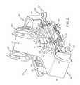
- FIG. 1is a perspective view of a hospital bed having a patient support deck in a horizontal position and having three of four siderails in a raised position with a fourth of the four siderails in a lowered position;
- FIG. 2is a perspective view of the hospital bed of FIG. 1 having the patient support deck in a chair egress position;
- FIG. 3is a diagrammatic side view of the hospital bed of FIGS. 1 and 2 showing a lift system supporting an upper frame and the patient support deck at a high elevation in the chair egress position to accommodate a tall patient;
- FIG. 4is a diagrammatic side view, similar to FIG. 3 , showing the lift system supporting the upper frame and the patient support deck at a low elevation in the chair egress position to accommodate a short patient;
- FIG. 5is a front elevation view of a graphical user interface having buttons or icons that are used to enter a patient's height into a control system of the hospital bed;
- FIG. 6is a block diagram showing a patient's height data and/or weight data being communicated to the hospital bed from a remote computer;
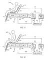
- FIG. 7is a diagrammatic view of a mattress of the hospital bed showing a pneumatic control system being commanded by control circuitry to deflate one or more air bladders of a foot section of the mattress in connection with the mattress moving into the chair egress position;
- FIG. 8is a diagrammatic view of the mattress, similar to FIG. 7 , showing the pneumatic control system being commanded by the control circuitry to deflate one or more aid bladders of a seat section of the mattress to accommodate a low weight patient during the patient's egress from the hospital bed;
- FIG. 9is a diagrammatic view of the mattress, similar to FIGS. 7 and 8 , showing the pneumatic control system being commanded by the control circuitry to further inflate one or more aid bladders of the seat section of the mattress to accommodate a high weight patient during the patient's egress from the hospital bed;
- FIG. 10is a flow chart showing an algorithm that is executed by the control circuitry in determining whether to deflate or further inflate the one or more seat section bladders in response to a caregiver activating an egress button;
- FIG. 11is a diagrammatic view showing the mattress in the chair egress position supported on the upper frame, the upper frame including a set of load cells that provide signals to a scale/patient position monitoring (PPM) system, and the one or more bladders of the seat section being inflated because the scale/PPM system senses that the patient is reclining on the mattress of the hospital bed;
- PPMscale/patient position monitoring
- FIG. 12is a diagrammatic view, similar to FIG. 11 , showing the one or more bladders of the seat section being deflated because the scale/PPM system senses that the patient is moving toward egressing from the hospital bed; and
- FIG. 13is a diagrammatic view, similar to FIGS. 11 and 12 , showing the one or more bladders of the seat section being re-inflated because the scale/PPM system senses that the patient has egressed from the hospital bed by a sufficient amount.
- a patient support apparatussuch as an illustrative hospital bed 10
- the lift system and/or pneumatic control systemare operated differently during the chair egress mode as will be discussed in further detail below.
- Illustrative bed 10is a so-called chair bed that is movable between a bed position as shown in FIG. 1 and a chair egress position as shown in FIG. 2 .
- teachings of this disclosureare applicable to other types of patient support apparatuses such as stretchers, motorized chairs, operating room (OR) tables, and specialty surgical tables such as orthopedic surgery tables, examination tables, and the like.
- hospital bed 10provides support to a patient (not shown) lying in a horizontal position when bed 10 is in the bed position shown in FIG. 1 and hospital bed 10 supports the patient in a sitting position such that the patient sits on bed 10 with the patient's feet positioned on an underlying floor when bed 10 is in the chair egress position shown in FIG. 2 .
- Hospital bed 10includes a frame 20 that supports a mattress 22 as shown in FIGS. 1 and 2 .
- Bed 10has a head end 24 and a foot end 26 .
- Frame 20includes a base 28 and an upper frame 30 coupled to the base 28 by a lift system 32 .
- Lift system 32is operable to raise, lower, and tilt upper frame 30 relative to base 28 .
- Hospital bed 10further includes a footboard 45 at the foot end 26 and a headboard 46 at the head end 24 . Footboard 45 is removed prior to bed 10 being moved into the chair egress position as shown in FIG. 2 .
- Base 28includes wheels or casters 29 that roll along the floor as bed 10 is moved from one location to another.
- Illustrative hospital bed 10has four siderail assemblies coupled to upper frame 30 : a patient-right head siderail assembly 48 , a patient-right foot siderail assembly 18 , a patient-left head siderail assembly 50 , and a patient-left foot siderail assembly 16 .
- Each of the siderail assemblies 16 , 18 , 48 , and 50is movable between a raised position, as the left foot siderail assembly 16 is shown in FIG. 1 , and a lowered position, as the right foot siderail assembly 18 is shown in FIG. 1 .
- Siderail assemblies 16 , 18 , 48 , 50are sometimes referred to herein as siderails 16 , 18 , 48 , 50 .
- the left foot siderail assembly 16is similar to the other siderail assemblies 18 , 48 , 50 , and thus, the following discussion of the left foot siderail assembly 16 is equally applicable to the other siderail assemblies 18 , 48 , 50 unless specifically noted otherwise.
- the left foot siderail 16includes a barrier panel 52 and a linkage 56 .
- Linkage 56is coupled to the upper frame 30 and is configured to guide barrier panel 52 during movement of the foot siderail 16 between the raised and lowered positions.
- Barrier panel 52is maintained by the linkage 56 in a substantially vertical orientation during movement of siderail 16 between the raised and lowered positions.
- the barrier panel 52includes an outward side 58 , an oppositely facing inward side 59 , a top portion 62 , and a bottom portion 64 .
- a graphical user interface 66is coupled to the outward side 58 of barrier panel 52 for use by a caregiver (not shown).
- the inward side 59faces opposite the outward side 58 .
- another user interface 67is coupled to the inward side 59 for use by the patient.
- user interface 66comprises a touchscreen display.
- a separate caregiver user interface 65is provided on the outward side 58 of barrier panel 52 .
- User interface 65includes a variety of buttons, such as membrane switches, for example, that are used to control various bed functions. Additional details of user interface 65 are provided in U.S. application Ser. No.
- user interface 65includes a chair egress mode button 69 as shown generically in FIGS. 1 and 2 .
- Mattress 22includes a top surface 34 , a bottom surface (not shown), and a perimeter surface 36 as shown in FIGS. 1 and 2 .
- the upper frame 30carries a mattress support deck 38 of frame 20 that engages the bottom surface of mattress 22 .
- the support deck 38as shown for example in FIG. 2 and as shown diagrammatically in FIGS. 3 and 4 , includes a head section 40 , a seat section 42 , a thigh section 43 and a foot section 44 .
- Each of sections 40 , 43 , 44is movable relative to upper frame 30 .
- head section 40pivotably raises and lowers relative to seat section 42 whereas foot section 44 pivotably raises and lowers relative to thigh section 43 .
- thigh section 43articulates relative to seat section 42 .
- foot section 44is extendable and retractable to change the overall length of foot section 44 and therefore, to change the overall length of deck 38 .
- foot section 44includes a main portion 45 and an extension 47 as shown in FIG. 1 .
- seat section 42is also movable relative to upper frame 30 such as by pivoting and/or translating relative to upper frame 30 .
- foot section 44lowers relative to thigh section 43 and shortens in length due to retraction of the extension 47 relative to main portion 45 .
- foot section 44raises relative to thigh section 43 and increases in length due to extension of the extension 47 relative to main portion 45 .
- head section 40extends generally vertically upwardly from upper frame 30 and foot section extends generally vertically downwardly from thigh section 43 as shown in FIG. 2 and as shown diagrammatically in FIGS. 3 and 4 .
- mattress support deck 38 and upper frame 30are in a horizontal position.
- lift system 32is operable to raise, lower, and tilt upper frame 30 relative to base 28 .
- lift system 32includes a set of head end lift arms 78 and a set of foot end lift arms 80 (only one of which can be seen in FIG. 1 ) to accomplish the raising, lowering and tilting functions of upper frame 30 relative to base 28 .
- motors or actuatorsare operated to move arms 78 , 80 to lower upper frame 30 toward base 20 if frame 30 is in a raised position initially.
- bed 10has four foot pedals 84 coupled to base 28 on each side of base 28 .
- a first of pedals 84is depressed to raise upper frame 30 relative to base 28
- a second of pedals 84is used to lower frame 30 relative to base 28
- a third of pedals 84is used to raise head section 40 relative to upper frame 30
- a fourth of pedals 84is used to lower head section 40 relative to upper frame 30 .
- foot pedals 84are omitted.
- bed 10includes various actuators or motors (not shown) to move lift arms 78 , 80 of lift system 32 , to move sections 40 , 43 , 44 relative to upper frame 30 , and to move section 42 , as well, in those embodiments in which section 42 moves relative to upper frame 30 .
- actuators or motors(not shown) to move lift arms 78 , 80 of lift system 32 , to move sections 40 , 43 , 44 relative to upper frame 30 , and to move section 42 , as well, in those embodiments in which section 42 moves relative to upper frame 30 .
- electric drive motorswith various types of transmission elements including lead screw drives and various types of mechanical linkages may be used to cause relative movement of portions of patient support apparatuses including raising, lowering, or tilting one portion of a bed relative to another.
- pneumatic or hydraulic actuatorsto actuate and/or move individual portions of patient support apparatuses.
- lift systems using scissors linkage arrangements or using vertically oriented telescoping structures, such as hydraulic cylinders or jack screwsare within the scope of this disclosure.
- electrically powered linear actuators to articulate deck sections 42 , 43 , 44 and to pivot arms 78 , 80are also within the scope of this disclosure.
- a seating surface of deck 38which for purposes of this discussion is arbitrarily defined by the upper surfaces of seat and thigh sections 42 , 43 , are moved to various target heights above the underlying floor when deck 38 is moved into the chair egress position.
- a hospital bedmay have only three deck sections such that the upper surface of only the middle or seat section may be considered to arbitrarily define the seating surface when the 3-section deck is moved into a chair egress position.
- FIG. 3a tall patient 100 is shown adjacent bed 10 and lift system 32 has been controlled so that the seating surface is located at a first height, h 1 , above the floor and, in FIG.
- a short patient 102is shown adjacent bed 10 and lift system 32 has been controlled so that the seating surface is located at a second height, h 2 , above the floor.
- Height h 1is the programmed height for the tall patient and is greater than h 2 which is programmed for the short patient.
- lift system 32is operated to place upper frame 30 and sections 42 , 43 at an elevation which is higher than for short patients. While patients 100 , 102 are shown next to bed 10 in FIGS. 3 and 4 , it should be understood that bed 10 is typically moved into the chair egress position while the patients are supported by mattress 22 on deck 38 .
- the height of the seating surfacegenerally corresponds to the popliteal height of the corresponding patient.
- the popliteal heightis the height from the floor, when the patient's feet are placed flat on the floor, up to the patient's popliteal, which is the part of the leg that bends behind the knee.
- the illustrative heights h 1 and h 2are simply two discrete elevations corresponding to patients having two discrete heights. However, it is contemplated by this disclosure that a spectrum of seating surface heights is achievable when bed 10 is in the chair egress position depending upon the height of the associated patient.
- lift system control algorithmsmay account for a large percentage, such as 90% for example, of the patient population such that a maximum seating surface height corresponds to patients at the 95 th percentile in height and such that the minimum seating surface height corresponds to patients at the 5 th percentile in height.
- a linear correlation, or other mathematical correlation if desired or appropriateis then used to establish the seating surface height when bed 10 is in the chair egress position. This is not to say that algorithms that account for a greater percentage or lesser percentage than 90% of the height of any given patient population are outside the scope of this disclosure.
- lift system 32is operable to place the seating surface at heights between about 19.3 inches and about 14.0 inches depending upon the height of the associated patient.
- a straight correlation curve or equationresults for determining seating surface height when bed 10 is in the chair egress position.
- a look up tablemay be programmed into the algorithm rather than using a curve or formula.
- different correlation curves, equations, and/or look up tablesmay be programmed for male patients and female patients, if desired, based on the anthropometric data for these two populations. Alternatively or additionally, it is also within the scope of this disclosure for different correlation curves to be programmed based on a comparison of popliteal height to overall height for different races and/or ethnicities.
- a caregiverin addition to the height data, a caregiver either enters data regarding the patient's sex, race, and/or ethnicity into the control system of bed 10 or such data is transmitted to the control system of bed 10 from a remote computer device, such as a computer device of an electronic medical records (EMR) system.
- EMRelectronic medical records
- an offset from the popliteal heightmay be included as part of the algorithm for determining seating surface height when bed 10 is in the chair egress position. For example, having the seating surface 1 or 2 inches, or more, below the popliteal height when bed 10 is in the chair egress position so that the patient can bend their legs at the knee more than 90 degrees prior to standing up from bed 10 may be desired in some instances. In other instances, it may be desired to have the seating surface 1 or 2 inches, or more, above the popliteal height when bed 10 is in the chair egress position so that the patient does not need to bend their legs at the knee quite as much while standing up from the bed 10 . One such instance may occur, for example, if the patient has had knee surgery and is unable to bend their legs at the knee more than 90 degrees.
- the offset from the popliteal heightmay be selectable on graphical user interface 66 in some embodiments.
- the height or elevation of the seating surface from the floorwas said to be the arbitrarily chosen distance of interest.
- the height above the floor of some other arbitrary reference point or plane on bed 10when bed 10 is in the chair egress position, may be monitored or calculated just as well.
- the top or bottom surface of upper frame 30could be chosen as the reference point or plane.
- the distance of the reference point or plane of some portion of the upper frame 30 or deck 38 above some other reference point or plane on base 28may be the distance that is monitored or calculated in some embodiments. Regardless of whether the position of upper frame 30 relative to base 28 is controlled based on patient height, or whether some other distance is controlled, the end result is that the seating surface height above the floor is varied based on patient height.
- the actuators or motors that move lift arms 78 , 80 of lift system 32have sensors, such as rotary potentiometers in some embodiments, and the signals from the sensors are used to determine the height of upper frame 30 relative to base.
- the sensorsmay include accelerometers or inclinometers on lift arms 78 , 80 which provide signals indicative of the angle of lift arms 78 , 80 relative to vertical or horizontal or relative to some other reference plane. Based on the information regarding the angle of lift arms 78 , 80 , the height of upper frame 30 above base 28 can be determined. Additional sensors may be provided on base 28 and/or upper frame 28 to indicate whether these portions of bed are at an angle other than horizontal such as will be the case with base 28 when bed 10 is being pushed up or down a ramp.
- a Select Patient Height screen 90 shown on graphical user interface 66has a feet up button 92 , a feet down button 94 , an inch up button 96 , and an inch down button 98 which are touched by a caregiver to enter a patient's height into the control system of the hospital bed.
- a bar graph 104 with a slider icon 106is also shown on screen 90 .
- Icon 106appears on graph 104 at the position corresponding to the height selected by the caregiver using buttons 92 , 94 , 96 , 98 .
- the caregiveris able to touch and drag icon 106 along graph 104 to change the height setting.
- a Ft/in button 108 and a M/cm button 110is provided to permit toggling between feet/inch units and meter/centimeter units.
- feet/inch unitshave been chosen so the patient's height in feet and inches are shown on screen 90 .
- the feet valueis shown between buttons 92 , 94 and the inch value is shown between buttons 96 , 98 .
- the gradations on graph 104are in feet/inches.
- M/cm button 110a meter value is shown between buttons 92 , 94
- a centimeter valueis shown between buttons 96 , 98
- the gradations on graph 104switch to meters/centimeters.
- buttons 92 , 94 , 96 , 98 or slider 106the user double taps a blank area on screen 90 in some embodiments to store the selected height in memory of the control system of bed 10 .
- screen 90includes an enter button that is touched for this purpose.
- the caregiverdoes not touch any of buttons 92 , 94 , 96 , 98 , 108 , 110 or slider 106 for a threshold amount of time, such as 10 or 15 seconds, for example, then the height value shown on screen 90 is stored in memory of the control system.
- the patient's height data and/or weight datais transmitted to bed 10 from a remote computer or system, such as a computer 112 of an electronic medical records (EMR) system, via communication infrastructure 114 and data links 116 , 118 as shown diagrammatically in FIG. 6 .
- EMRelectronic medical records
- the patient's height datais stored in memory 122 of control circuitry 120 regardless of whether the height data is transmitted to bed 10 or whether a caregiver has entered the data on screen 90 .
- bed 10includes a scale system 136 as will be discussed in further detail below. The scale system 136 is able to measure the patient's weight and then the measured weight is stored in memory 122 of control circuitry 120 .
- scale system 136also functions as a patient position monitoring (PPM) system and so is indicated as scale/PPM system 136 in FIGS. 11-13 .
- weight datais transmitted to bed 10 from a remote computer 112 as previously mentioned.
- computer 112is part of a nurse call system, a physician ordering system, an admission/discharge/transfer (ADT) system, or some other system used in a healthcare facility.
- Communication infrastructure 114 in FIG. 6is illustrated diagrammatically and is intended to represent all of the other hardware and software that comprises a network of a healthcare facility.
- Data links 116 , 118are wired communications links and/or wireless communication links.
- communications link 118in some embodiments, comprises a cable that connects bed 10 to a wall mounted jack that is included as part of a bed interface unit (BIU) or a network interface unit (NIU) of the type shown and described in U.S. Pat. Nos. 7,538,659 and 7,319,386 and in U.S. Patent Application Publication Nos. 2009/0217080 A1, 2009/0212925 A1 and 2009/0212926 A1, each of which are hereby expressly incorporated by reference herein.
- communications link 118comprises wireless signals sent between bed 10 and a wireless interface unit of the type shown and described in U.S. Patent Application Publication No. 2007/0210917 A1 which is hereby expressly incorporated by reference herein.
- Communications link 116also comprises one or more wired links and/or wireless links as previously noted.
- bed 10includes a pneumatic control system 124 that controls inflation and deflation of various air bladders or cells of mattress 22 .
- mattress 22 of bed 10has a set of head zone bladders 126 , a set of seat and thigh zone bladders 128 (sometimes referred to herein as just “seat zone bladders 128 ”), and a set of foot zone bladders 130 .
- Bladders 126 , 128 , 130are coupled to the pneumatic control system 124 via respective pneumatic lines 132 , 134 , 136 which comprise flexible tubes or hoses, for example.
- Pneumatic control system 124is illustrated diagrammatically and is intended to represent the various components such as one or more air sources including compressors, blowers, fans, pressure reservoirs, and the like; one or more manifolds; one or more valves; one or more pressure sensors; and the associated circuitry that controls the inflation and deflation of bladders 126 , 128 , 130 .
- Pneumatic control system 124is in electrical communication with the main control circuitry 120 of bed 10 as indicated diagrammatically by communications link 142 .
- communications link 142is a bidirectional communications link.
- head section 40raises as indicated by arrow 138 in FIG. 7 and foot section 44 lowers as indicated by arrow 140 in FIG. 7 .
- the portions of mattress 22 supported by deck sections 40 , 44raise and lower along with the respective deck sections 40 , 44 in directions 138 , 140 , respectively.
- pneumatic control system 124is operated to deflate the set of foot zone bladders 130 such that air is evacuated from bladders 130 via line 136 as shown in FIG. 7 .
- pressure adjustmentsare also made in seat zone bladders 128 and/or head zone bladders 126 .
- bladders 128are further inflated in some embodiments to prevent or lessen the chance of the patient bottoming out on the seat section 42 of deck 38 .
- Bottoming outrefers to the situation in which a patient completely crushes or deforms a mattress bladder to the extent that the patient feels the underlying deck section.
- the state of inflation and deflation of bladders 126 , 128 , 130 shown in FIG. 7corresponds to the situation in which bed 10 is moved to the chair egress position and the patient intends to remain sitting in the bed 10 for some period of time.
- the caregiverpresses or touches chair egress button 69 of user interface 65 to activate the chair egress mode of bed 10 .
- the pneumatic control system 124operates either to deflate seat zone bladders 128 for lighter patients as shown in FIG. 8 or to further inflate seat zone bladders 128 for heavier patients as shown in FIG. 9 .
- a light weight patient 200is shown adjacent bed 10 and system 124 has been operated so that seat zone bladders 128 are deflated via line 134 and, in FIG. 9 , a heavy weight patient 202 is shown adjacent bed 10 and system 124 has been operated so that seat zone bladders 128 are further inflated via line 134 .
- FIG. 10A block diagram illustrative of the algorithm executed by the control system of bed 10 to determine whether to deflate or further inflate bladders 128 in response to the activation of chair egress button 69 is shown in FIG. 10 .
- the control circuitry 120 , pneumatic control system 124 , and scale/PPM system 136are considered to be a control system of bed 10 according to this disclosure.
- the control system of bed 10includes additional circuitry in some embodiments, such as power control circuitry, battery recharging circuitry, and so forth.
- a control system of a patient support apparatus, such as bed 10is considered to be some or all of the electrical hardware and software that controls, operates, or is associated with any of the functions of the patient support apparatus.
- the algorithm of FIG. 10begins as a result of the caregiver pressing or activating the chair egress button 69 as indicated at block 150 .
- the control system of bed 10reads the patient weight as indicated at block 152 .
- the control systemcompares the patient's weight to a threshold value, X, as indicated at block 154 . If the patient's weight is above the threshold amount of weight, then bladders 128 are further inflated as indicated at block 156 . If the patient's weight is equal to or below the threshold amount of weight, then bladders 128 are deflated as indicated at block 158 .
- bladders 128are deflated or further inflated in response to the chair egress button 69 being activated, the result is that the surface on which the patient is sitting just prior to egressing from bed 10 is made firmer, thereby making it easier for the patient to get up out of the bed.
- the patient's immersion into the seat regionwhich as mentioned previously presents an egress impediment in some prior art beds, is lessened or substantially eliminated by further inflating bladders 128 or by deflating them.
- the threshold amount of weight for determining whether to deflate or further inflate bladders 128may be in the range of 200 to 300 pounds in some embodiments, for example. Thresholds that are greater than or lesser than this range are within the scope of this disclosure. The threshold amount of weight is at the discretion of the system designer and/or programmer and is dependent upon a number of factors including, for example, whether there is a base foam layer or some other cushioning element beneath or atop bladders 128 .
- bladders 128may remain at their current level of inflation rather than being further inflated.
- upper frame 30 of bed 10in the illustrative example, includes a lift frame 160 and a weight frame 162 which is supported relative to the lift frame 160 by a set of load cells 164 .
- load cells 164are illustrated diagrammatically. However, a common arrangement for hospital beds is to have four load cells arranged at the corners of an imaginary rectangle, for example, and such an arrangement is certainly within the scope of this disclosure.
- Each of the load cells 164include a mass of material that deflects under the weight of the load carried by weigh frame 162 , and the deflection is sensed by one or more strain gages mounted to the mass of material.
- the one or more strain gages of load cells 164are electrically coupled to the scale/PPM system by lines 166 .
- the current or voltage sensed on lines 166correlates to the amount of deflection of load cells 164 and therefore, to the amount of weight supported by load cells 164 .
- the tare weighti.e., the weight of everything supported by load cells 164 other than the patient
- the patient's weightcan be determined.
- the position of the patient on bed 10can be determined. See, for example, U.S. Pat. No. 7,253,366 which shows and describes such a scale/PPM system and which is hereby expressly incorporated by reference herein.
- the signals from the load cells 164are used to determine a position of the patient's center of gravity relative to a plane passing through the load cells 164 .
- other types of weight sensorssuch as force sensitive resistors (FSR's), capacitive sensors, linear variable displacement transducers (LVDT's), or the like are used in lieu of, or in addition to, load cells 164 to provide signals for determining a patient's weight or position.
- FSR'sforce sensitive resistors
- LVDT'slinear variable displacement transducers
- bladders 128are inflated. As the patient begins to egress from bed 10 and moves or leans toward the foot end of the seating surface, as shown in FIG. 12 , the scale/PPM system 136 senses this movement based on the signals from load cells 164 and bladders 128 are deflated by the pneumatic control system 124 . When the patient begins to stand up from bed 10 and transfers weight off of bed 10 , as shown in FIG. 13 , this is also sensed by the scale/PPM system 136 based on signals from load cells 164 and bladders 128 are re-inflated.
- bladders 128By re-inflating bladders 128 as the patient stands up, a softer seating area is created in the event that the patient inadvertently falls back onto the bed 10 during the egress process. This protects the patient from falling back down onto a hard seating surface.
- a threshold amount of timesuch as 10 to 30 seconds
- the bladders 128are again deflated to ready the bed 10 for the patient's return.
- the threshold amount of timethe patient is assumed to have successfully egressed from the bed 10 , is standing up, and is no longer at risk of falling back down onto bed 10 .
- the deflation, re-inflation, and then re-deflation of bladders 128 just describedis contemplated as being a feature of bed 10 that is used with lighter weight patients.
- bladders 128are already inflated and so if the heavier patients fall back down onto the bed 10 during egress, they will not encounter the type of hard seating surface of the underlying deck sections 42 , 43 .
- the deflation, re-inflation, and then re-deflation of bladders 128occurs only after chair egress button 69 has been pressed or otherwise activated.
- the deflation, re-inflation, and re-deflation functionoccurs automatically based on the movement of the patient sensed by the scale/PPM system 136 .
- the bladders 128after bladders 128 have been deflated and re-inflated during the egress process, the bladders 128 remain re-inflated for the patient's return to bed 10 .
Landscapes
- Health & Medical Sciences (AREA)
- Nursing (AREA)
- Life Sciences & Earth Sciences (AREA)
- Animal Behavior & Ethology (AREA)
- General Health & Medical Sciences (AREA)
- Public Health (AREA)
- Veterinary Medicine (AREA)
- Invalid Beds And Related Equipment (AREA)
Abstract
Description
Claims (19)
Priority Applications (2)
| Application Number | Priority Date | Filing Date | Title |
|---|---|---|---|
| US12/951,158US8413273B2 (en) | 2010-11-22 | 2010-11-22 | Control of hospital bed chair egress configuration based on patient physiology |
| US13/855,833US8844078B2 (en) | 2010-11-22 | 2013-04-03 | Control of hospital bed chair egress configuration based on patient physiology |
Applications Claiming Priority (1)
| Application Number | Priority Date | Filing Date | Title |
|---|---|---|---|
| US12/951,158US8413273B2 (en) | 2010-11-22 | 2010-11-22 | Control of hospital bed chair egress configuration based on patient physiology |
Related Child Applications (1)
| Application Number | Title | Priority Date | Filing Date |
|---|---|---|---|
| US13/855,833ContinuationUS8844078B2 (en) | 2010-11-22 | 2013-04-03 | Control of hospital bed chair egress configuration based on patient physiology |
Publications (2)
| Publication Number | Publication Date |
|---|---|
| US20120124744A1 US20120124744A1 (en) | 2012-05-24 |
| US8413273B2true US8413273B2 (en) | 2013-04-09 |
Family
ID=46062932
Family Applications (2)
| Application Number | Title | Priority Date | Filing Date |
|---|---|---|---|
| US12/951,158Active2031-05-26US8413273B2 (en) | 2010-11-22 | 2010-11-22 | Control of hospital bed chair egress configuration based on patient physiology |
| US13/855,833ActiveUS8844078B2 (en) | 2010-11-22 | 2013-04-03 | Control of hospital bed chair egress configuration based on patient physiology |
Family Applications After (1)
| Application Number | Title | Priority Date | Filing Date |
|---|---|---|---|
| US13/855,833ActiveUS8844078B2 (en) | 2010-11-22 | 2013-04-03 | Control of hospital bed chair egress configuration based on patient physiology |
Country Status (1)
| Country | Link |
|---|---|
| US (2) | US8413273B2 (en) |
Cited By (16)
| Publication number | Priority date | Publication date | Assignee | Title |
|---|---|---|---|---|
| US20110301440A1 (en)* | 2010-06-07 | 2011-12-08 | Riley Carl W | Apparatus for supporting and monitoring a person |
| US20130227788A1 (en)* | 2012-03-05 | 2013-09-05 | Jonathan D. Turner | Articulable Bed with a Translatable and Orientation Adjustable Deck Section and Volumetrically Adjustable Compensatory Element |
| US8844078B2 (en) | 2010-11-22 | 2014-09-30 | Hill-Rom Services, Inc. | Control of hospital bed chair egress configuration based on patient physiology |
| US9655457B2 (en) | 2012-06-21 | 2017-05-23 | Hill-Rom Services, Inc. | Patient support systems and methods of use |
| US9833369B2 (en) | 2012-06-21 | 2017-12-05 | Hill-Rom Services, Inc. | Patient support systems and methods of use |
| US10123924B2 (en) | 2013-11-15 | 2018-11-13 | Hill-Rom S.A.S. | System and method for automatically adjusting the height of a patient support |
| US10489661B1 (en) | 2016-03-08 | 2019-11-26 | Ocuvera LLC | Medical environment monitoring system |
| US10600204B1 (en) | 2016-12-28 | 2020-03-24 | Ocuvera | Medical environment bedsore detection and prevention system |
| US11052005B2 (en) | 2017-09-19 | 2021-07-06 | Stryker Corporation | Patient support apparatus with handles for patient ambulation |
| US11116680B2 (en) | 2017-09-19 | 2021-09-14 | Stryker Corporation | Patient support apparatus for controlling patient ingress and egress |
| US11160705B2 (en) | 2017-10-20 | 2021-11-02 | Stryker Corporation | Adjustable patient support apparatus for assisted egress and ingress |
| US11202729B2 (en)* | 2017-06-27 | 2021-12-21 | Stryker Corporation | Patient support apparatus user interfaces |
| US11484451B1 (en) | 2017-06-27 | 2022-11-01 | Stryker Corporation | Patient support apparatus user interfaces |
| US11666497B2 (en) | 2018-10-22 | 2023-06-06 | Hill-Rom Services, Inc. | System for adjusting the configuration of a patient support apparatus |
| US12036161B2 (en) | 2019-08-16 | 2024-07-16 | Stryker Corporation | Patient support with deck width monitoring and control |
| US12102577B2 (en) | 2012-06-21 | 2024-10-01 | Hill-Rom Services, Inc. | Mattress bladder control using a bleed valve |
Families Citing this family (32)
| Publication number | Priority date | Publication date | Assignee | Title |
|---|---|---|---|---|
| US9901503B2 (en) | 2008-03-13 | 2018-02-27 | Optimedica Corporation | Mobile patient bed |
| US8978181B2 (en) | 2012-03-21 | 2015-03-17 | Midmark Corporation | Medical examination table with integrated scale |
| US20140000030A1 (en)* | 2012-06-18 | 2014-01-02 | Hill-Rom Services, Inc. | Lift system for a person support apparatus |
| USD707463S1 (en)* | 2013-03-13 | 2014-06-24 | Ruoey Lung Enterprise Corp. | Adjustable bed |
| WO2014150970A1 (en)* | 2013-03-15 | 2014-09-25 | Stryker Corporation | Patient support apparatus with remote communications |
| AU2014317772B2 (en) | 2013-09-06 | 2019-04-11 | Stryker Corporation | Patient support usable with bariatric patients |
| US10188569B2 (en) | 2013-09-06 | 2019-01-29 | Stryker Corporation | Patient support usable with bariatric patients |
| US9259098B2 (en) | 2013-12-06 | 2016-02-16 | Hill-Rom Services, Inc. | Inflatable patient positioning unit |
| US9408477B1 (en)* | 2014-06-16 | 2016-08-09 | William A. Robinson | Portable pneumatic seating device |
| CN118078551A (en)* | 2015-05-29 | 2024-05-28 | 希尔-罗姆服务公司 | Patient support equipment |
| US11020295B2 (en) | 2015-12-22 | 2021-06-01 | Stryker Corporation | Patient support systems and methods for assisting caregivers with patient care |
| US10736803B2 (en) | 2016-02-26 | 2020-08-11 | Stryker Corporation | Lift assembly for patient support apparatus |
| CZ308132B6 (en)* | 2016-05-12 | 2020-01-15 | Linet Spol. S.R.O. | Mattress with automatic pressure optimization |
| US10813806B2 (en) | 2016-05-24 | 2020-10-27 | Stryker Corporation | Medical support apparatus with stand assistance |
| US10842701B2 (en) | 2016-10-14 | 2020-11-24 | Stryker Corporation | Patient support apparatus with stabilization |
| US10235845B2 (en)* | 2017-04-05 | 2019-03-19 | Stryker Corporation | Patient support apparatuses with reconfigurable communication |
| US10987268B2 (en) | 2017-04-21 | 2021-04-27 | Stryker Corporation | Emergency cot with a litter height adjustment mechanism |
| US10987260B2 (en) | 2017-04-21 | 2021-04-27 | Stryker Corporation | Patient handling apparatus with hydraulic control system |
| JP6769922B2 (en)* | 2017-05-01 | 2020-10-14 | パラマウントベッド株式会社 | Electric furniture |
| EP3476380B1 (en) | 2017-10-24 | 2020-05-13 | Hill-Rom Services, Inc. | Modular turn assist apparatus and method therefor |
| EP3764968B1 (en)* | 2018-03-14 | 2024-10-23 | Ka Shek Neville Lee | Patient transfer system |
| US12042453B2 (en) | 2019-02-26 | 2024-07-23 | Hill-Rom Services, Inc. | Patient positioning apparatus and mattress |
| US11911325B2 (en)* | 2019-02-26 | 2024-02-27 | Hill-Rom Services, Inc. | Bed interface for manual location |
| US11583455B2 (en) | 2019-10-28 | 2023-02-21 | Stryker Corporation | Hydraulic valve and system |
| US11896531B2 (en) | 2019-10-28 | 2024-02-13 | Stryker Corporation | Hydraulic circuit for a patient handling apparatus |
| US11730650B2 (en) | 2019-12-30 | 2023-08-22 | Stryker Corporation | Patient support apparatus with hydraulic oscillation dampening |
| US11986429B2 (en)* | 2020-05-13 | 2024-05-21 | Stryker Corporation | Patient transport apparatus with automatic height adjustment |
| JP6999006B2 (en)* | 2020-09-25 | 2022-01-18 | パラマウントベッド株式会社 | Control device |
| JP7270716B2 (en)* | 2020-09-25 | 2023-05-10 | パラマウントベッド株式会社 | Control device |
| JP7393101B2 (en)* | 2020-11-30 | 2023-12-06 | トヨタ自動車株式会社 | sleeping equipment |
| US20220313526A1 (en)* | 2021-03-30 | 2022-10-06 | Hill-Rom Services, Inc. | Bed and mattress auto settings for intubation |
| US12350212B2 (en)* | 2021-05-28 | 2025-07-08 | Stryker Corporation | Patient transport apparatus with electro-mechanical braking input hold circuit |
Citations (34)
| Publication number | Priority date | Publication date | Assignee | Title |
|---|---|---|---|---|
| US5060896A (en) | 1987-05-08 | 1991-10-29 | Hobbins John C | Furniture adjustment device |
| US5715548A (en) | 1994-01-25 | 1998-02-10 | Hill-Rom, Inc. | Chair bed |
| US5790997A (en) | 1995-08-04 | 1998-08-11 | Hill-Rom Inc. | Table/chair egress device |
| US6056353A (en) | 1998-11-16 | 2000-05-02 | Meara; Laura | Folding adjustable chair to accommodate joint dysfunction |
| US6155641A (en) | 1997-12-16 | 2000-12-05 | Frost; Beverly J. | Variable height chair adaptable for growing children |
| US6347420B2 (en) | 2000-04-12 | 2002-02-19 | Franklin E. Elliott | System for producing anthropometric, adjustable, articulated beds |
| US6721980B1 (en) | 1998-10-28 | 2004-04-20 | Hill-Fom Services, Inc. | Force optimization surface apparatus and method |
| US20040189073A1 (en) | 2003-03-28 | 2004-09-30 | Donald Chadwick | Adjustable chair |
| US7036166B2 (en) | 2001-03-27 | 2006-05-02 | Hil-Rom Service, Inc. | Hospital bed |
| US20070169268A1 (en)* | 2005-12-19 | 2007-07-26 | Stryker Corporation | Hospital bed |
| US7253366B2 (en) | 2004-08-09 | 2007-08-07 | Hill-Rom Services, Inc. | Exit alarm for a hospital bed triggered by individual load cell weight readings exceeding a predetermined threshold |
| US20070210917A1 (en) | 2004-08-02 | 2007-09-13 | Collins Williams F Jr | Wireless bed connectivity |
| US7296312B2 (en) | 2002-09-06 | 2007-11-20 | Hill-Rom Services, Inc. | Hospital bed |
| US7319386B2 (en) | 2004-08-02 | 2008-01-15 | Hill-Rom Services, Inc. | Configurable system for alerting caregivers |
| US7458119B2 (en) | 2004-07-30 | 2008-12-02 | Hill-Rom Services, Inc. | Bed having a chair egress position |
| US20090000033A1 (en)* | 2007-06-27 | 2009-01-01 | James Christopher Hempker | Patient table with footrest extension |
| US20090038074A1 (en)* | 2005-04-21 | 2009-02-12 | Hans-Peter Barthelt | Hospital Bed with Double-Motor Drive |
| US20090044334A1 (en) | 2007-08-13 | 2009-02-19 | Valence Broadband, Inc. | Automatically adjusting patient platform support height in response to patient related events |
| US7512998B2 (en)* | 2006-06-15 | 2009-04-07 | Martin Manufacturing Company, Llc | Examination table |
| US7538659B2 (en) | 1993-07-12 | 2009-05-26 | Hill-Rom Services, Inc. | Bed status information system for hospital beds |
| US20090212926A1 (en) | 2008-02-23 | 2009-08-27 | Ruoping Du | Baby Monitor |
| US20090212925A1 (en) | 2008-02-22 | 2009-08-27 | Schuman Sr Richard Joseph | User station for healthcare communication system |
| US7644460B2 (en) | 2006-10-23 | 2010-01-12 | Orlando Calvo | Device and method for relieving back pain |
| US20100064439A1 (en)* | 2008-09-12 | 2010-03-18 | Sohrab Soltani | Hospital chair beds with articulating foot sections |
| US7779547B2 (en) | 2004-06-07 | 2010-08-24 | Robin Townsend | Apparatus and method for setting furniture height |
| US7797771B1 (en) | 2002-06-03 | 2010-09-21 | Atlas Ergonomics, L.L.C. | System and method for optimally determining appropriate ergonomics for occupants of a workspace |
| US20100244522A1 (en) | 2009-03-27 | 2010-09-30 | Oki Electric Industry Co., Ltd. | Chair providing more comfortable when seated in optimum posture while reclining |
| US20100293718A1 (en)* | 2005-04-06 | 2010-11-25 | Byron Wade Wurdeman | Hospital beds with a rotating sleep surface that can translate into a chair configuration |
| US20110047704A1 (en)* | 2005-07-28 | 2011-03-03 | The Brewer Company, Llc | Medical examination table |
| US8028359B2 (en)* | 2005-04-04 | 2011-10-04 | Raye's, Inc. | Automated multi-functional support apparatus |
| US8051512B2 (en)* | 2009-07-15 | 2011-11-08 | Teeter Roger C | Patient treatment apparatus |
| US20120023673A1 (en)* | 2010-07-30 | 2012-02-02 | Hornbach David W | Bed Frame Assembly with a Lift System having a Translatable Carriage |
| US20120047655A1 (en)* | 2010-08-26 | 2012-03-01 | O'keefe Christopher R | Incline based bed height |
| US20120060290A1 (en)* | 2010-09-09 | 2012-03-15 | Midmark Corporation | Brushless dc motor braking for a barrier free medical table |
Family Cites Families (3)
| Publication number | Priority date | Publication date | Assignee | Title |
|---|---|---|---|---|
| EP0403073A3 (en)* | 1989-05-12 | 1991-07-24 | Patreen Associates Limited | A bed |
| IT1233633B (en)* | 1989-06-28 | 1992-04-07 | Claudio Corradi | MOBILE EQUIPMENT SUITABLE IN PARTICULAR TO ALLOW THE TRANSPORT OF SICK FROM THE BED TO THE EQUIPMENT ITSELF AND VICEVERSA |
| US8413273B2 (en) | 2010-11-22 | 2013-04-09 | Hill-Rom Services, Inc. | Control of hospital bed chair egress configuration based on patient physiology |
- 2010
- 2010-11-22USUS12/951,158patent/US8413273B2/enactiveActive
- 2013
- 2013-04-03USUS13/855,833patent/US8844078B2/enactiveActive
Patent Citations (42)
| Publication number | Priority date | Publication date | Assignee | Title |
|---|---|---|---|---|
| US5060896A (en) | 1987-05-08 | 1991-10-29 | Hobbins John C | Furniture adjustment device |
| US7538659B2 (en) | 1993-07-12 | 2009-05-26 | Hill-Rom Services, Inc. | Bed status information system for hospital beds |
| US5715548A (en) | 1994-01-25 | 1998-02-10 | Hill-Rom, Inc. | Chair bed |
| US5790997A (en) | 1995-08-04 | 1998-08-11 | Hill-Rom Inc. | Table/chair egress device |
| US6155641A (en) | 1997-12-16 | 2000-12-05 | Frost; Beverly J. | Variable height chair adaptable for growing children |
| US7515059B2 (en) | 1998-10-28 | 2009-04-07 | Hill-Rom Services, Inc. | Patient support surface with physiological sensors |
| US6721980B1 (en) | 1998-10-28 | 2004-04-20 | Hill-Fom Services, Inc. | Force optimization surface apparatus and method |
| US7330127B2 (en) | 1998-10-28 | 2008-02-12 | Hill-Rom Services, Inc. | Force optimization surface apparatus and method |
| US6056353A (en) | 1998-11-16 | 2000-05-02 | Meara; Laura | Folding adjustable chair to accommodate joint dysfunction |
| US20080201851A1 (en)* | 1999-12-29 | 2008-08-28 | Menkedick Douglas J | Lift system for hospital bed |
| US6516480B2 (en) | 2000-04-12 | 2003-02-11 | Franklin E. Elliott | System for producing anthropometric, adjustable, articulated beds |
| US6347420B2 (en) | 2000-04-12 | 2002-02-19 | Franklin E. Elliott | System for producing anthropometric, adjustable, articulated beds |
| US7036166B2 (en) | 2001-03-27 | 2006-05-02 | Hil-Rom Service, Inc. | Hospital bed |
| US7610638B2 (en) | 2001-03-27 | 2009-11-03 | Hill-Rom Services, Inc. | Hospital bed |
| US7797771B1 (en) | 2002-06-03 | 2010-09-21 | Atlas Ergonomics, L.L.C. | System and method for optimally determining appropriate ergonomics for occupants of a workspace |
| US7296312B2 (en) | 2002-09-06 | 2007-11-20 | Hill-Rom Services, Inc. | Hospital bed |
| US20040189073A1 (en) | 2003-03-28 | 2004-09-30 | Donald Chadwick | Adjustable chair |
| US7779547B2 (en) | 2004-06-07 | 2010-08-24 | Robin Townsend | Apparatus and method for setting furniture height |
| US7458119B2 (en) | 2004-07-30 | 2008-12-02 | Hill-Rom Services, Inc. | Bed having a chair egress position |
| US7319386B2 (en) | 2004-08-02 | 2008-01-15 | Hill-Rom Services, Inc. | Configurable system for alerting caregivers |
| US20070210917A1 (en) | 2004-08-02 | 2007-09-13 | Collins Williams F Jr | Wireless bed connectivity |
| US7253366B2 (en) | 2004-08-09 | 2007-08-07 | Hill-Rom Services, Inc. | Exit alarm for a hospital bed triggered by individual load cell weight readings exceeding a predetermined threshold |
| US8028359B2 (en)* | 2005-04-04 | 2011-10-04 | Raye's, Inc. | Automated multi-functional support apparatus |
| US8127380B2 (en)* | 2005-04-06 | 2012-03-06 | Piedmont Global Solutions, Inc. | Hospital beds with a rotating sleep surface that can translate into a chair configuration |
| US20100293718A1 (en)* | 2005-04-06 | 2010-11-25 | Byron Wade Wurdeman | Hospital beds with a rotating sleep surface that can translate into a chair configuration |
| US20090038074A1 (en)* | 2005-04-21 | 2009-02-12 | Hans-Peter Barthelt | Hospital Bed with Double-Motor Drive |
| US20110047704A1 (en)* | 2005-07-28 | 2011-03-03 | The Brewer Company, Llc | Medical examination table |
| US20110277242A1 (en)* | 2005-11-07 | 2011-11-17 | Stryker Corporation | Hospital bed |
| US20070169268A1 (en)* | 2005-12-19 | 2007-07-26 | Stryker Corporation | Hospital bed |
| US7512998B2 (en)* | 2006-06-15 | 2009-04-07 | Martin Manufacturing Company, Llc | Examination table |
| US7644460B2 (en) | 2006-10-23 | 2010-01-12 | Orlando Calvo | Device and method for relieving back pain |
| US20090000033A1 (en)* | 2007-06-27 | 2009-01-01 | James Christopher Hempker | Patient table with footrest extension |
| US20090044334A1 (en) | 2007-08-13 | 2009-02-19 | Valence Broadband, Inc. | Automatically adjusting patient platform support height in response to patient related events |
| US20090217080A1 (en) | 2008-02-22 | 2009-08-27 | Ferguson David C | Distributed fault tolerant architecture for a healthcare communication system |
| US20090212925A1 (en) | 2008-02-22 | 2009-08-27 | Schuman Sr Richard Joseph | User station for healthcare communication system |
| US20090212926A1 (en) | 2008-02-23 | 2009-08-27 | Ruoping Du | Baby Monitor |
| US20100064439A1 (en)* | 2008-09-12 | 2010-03-18 | Sohrab Soltani | Hospital chair beds with articulating foot sections |
| US20100244522A1 (en) | 2009-03-27 | 2010-09-30 | Oki Electric Industry Co., Ltd. | Chair providing more comfortable when seated in optimum posture while reclining |
| US8051512B2 (en)* | 2009-07-15 | 2011-11-08 | Teeter Roger C | Patient treatment apparatus |
| US20120023673A1 (en)* | 2010-07-30 | 2012-02-02 | Hornbach David W | Bed Frame Assembly with a Lift System having a Translatable Carriage |
| US20120047655A1 (en)* | 2010-08-26 | 2012-03-01 | O'keefe Christopher R | Incline based bed height |
| US20120060290A1 (en)* | 2010-09-09 | 2012-03-15 | Midmark Corporation | Brushless dc motor braking for a barrier free medical table |
Cited By (24)
| Publication number | Priority date | Publication date | Assignee | Title |
|---|---|---|---|---|
| US8844073B2 (en)* | 2010-06-07 | 2014-09-30 | Hill-Rom Services, Inc. | Apparatus for supporting and monitoring a person |
| US20110301440A1 (en)* | 2010-06-07 | 2011-12-08 | Riley Carl W | Apparatus for supporting and monitoring a person |
| US8844078B2 (en) | 2010-11-22 | 2014-09-30 | Hill-Rom Services, Inc. | Control of hospital bed chair egress configuration based on patient physiology |
| US20130227788A1 (en)* | 2012-03-05 | 2013-09-05 | Jonathan D. Turner | Articulable Bed with a Translatable and Orientation Adjustable Deck Section and Volumetrically Adjustable Compensatory Element |
| US9009895B2 (en)* | 2012-03-05 | 2015-04-21 | Hill-Rom Services, Inc. | Articulable bed with a translatable and orientation adjustable deck section and volumetrically adjustable compensatory element |
| US10806655B2 (en) | 2012-06-21 | 2020-10-20 | Hill-Rom Services, Inc. | Mattress bladder control during patient bed egress |
| US9655457B2 (en) | 2012-06-21 | 2017-05-23 | Hill-Rom Services, Inc. | Patient support systems and methods of use |
| US9833369B2 (en) | 2012-06-21 | 2017-12-05 | Hill-Rom Services, Inc. | Patient support systems and methods of use |
| US12102577B2 (en) | 2012-06-21 | 2024-10-01 | Hill-Rom Services, Inc. | Mattress bladder control using a bleed valve |
| US10555850B2 (en) | 2012-06-21 | 2020-02-11 | Hill-Rom Services, Inc. | Patient support systems and methods of use |
| US10881568B2 (en) | 2013-11-15 | 2021-01-05 | Hill-Rom S.A.S. | Method for automatically adjusting the height of a patient support |
| US10123924B2 (en) | 2013-11-15 | 2018-11-13 | Hill-Rom S.A.S. | System and method for automatically adjusting the height of a patient support |
| US10489661B1 (en) | 2016-03-08 | 2019-11-26 | Ocuvera LLC | Medical environment monitoring system |
| US10600204B1 (en) | 2016-12-28 | 2020-03-24 | Ocuvera | Medical environment bedsore detection and prevention system |
| US11484451B1 (en) | 2017-06-27 | 2022-11-01 | Stryker Corporation | Patient support apparatus user interfaces |
| US11559450B2 (en) | 2017-06-27 | 2023-01-24 | Stryker Corporation | Patient support apparatus user interfaces |
| US11202729B2 (en)* | 2017-06-27 | 2021-12-21 | Stryker Corporation | Patient support apparatus user interfaces |
| US11116680B2 (en) | 2017-09-19 | 2021-09-14 | Stryker Corporation | Patient support apparatus for controlling patient ingress and egress |
| US11723821B2 (en) | 2017-09-19 | 2023-08-15 | Stryker Corporation | Patient support apparatus for controlling patient ingress and egress |
| US11052005B2 (en) | 2017-09-19 | 2021-07-06 | Stryker Corporation | Patient support apparatus with handles for patient ambulation |
| US11160705B2 (en) | 2017-10-20 | 2021-11-02 | Stryker Corporation | Adjustable patient support apparatus for assisted egress and ingress |
| US11806290B2 (en) | 2017-10-20 | 2023-11-07 | Stryker Corporation | Adjustable patient support apparatus for assisted egress and ingress |
| US11666497B2 (en) | 2018-10-22 | 2023-06-06 | Hill-Rom Services, Inc. | System for adjusting the configuration of a patient support apparatus |
| US12036161B2 (en) | 2019-08-16 | 2024-07-16 | Stryker Corporation | Patient support with deck width monitoring and control |
Also Published As
| Publication number | Publication date |
|---|---|
| US20130219622A1 (en) | 2013-08-29 |
| US8844078B2 (en) | 2014-09-30 |
| US20120124744A1 (en) | 2012-05-24 |
Similar Documents
| Publication | Publication Date | Title |
|---|---|---|
| US8844078B2 (en) | Control of hospital bed chair egress configuration based on patient physiology | |
| US12023287B2 (en) | Inflatable mattress and control methods | |
| US10363181B2 (en) | Patient position detection for patient support apparatus | |
| US20230233391A1 (en) | Patient Support Systems And Methods For Assisting Caregivers With Patient Care | |
| US8640285B2 (en) | Hospital bed seat section articulation for chair egress | |
| EP2462912B1 (en) | Mattress bladder boosting during chair egress | |
| US12408845B2 (en) | Person support apparatus with adjustable exit detection zones | |
| US9233038B2 (en) | Patient support with a microclimate system and a graphical user interface | |
| EP2508128B1 (en) | Person support apparatus with activity and mobility sensing | |
| US20150182400A1 (en) | Patient support systems and methods of use | |
| EP2702939B1 (en) | Patient mobility assessment | |
| JP2017060773A (en) | Patient support systems and methods of use | |
| JP7504671B2 (en) | Air cell control device |
Legal Events
| Date | Code | Title | Description |
|---|---|---|---|
| AS | Assignment | Owner name:HILL-ROM SERVICES, INC., DELAWARE Free format text:ASSIGNMENT OF ASSIGNORS INTEREST;ASSIGNORS:HORNBACH, DAVID W.;BHAI, AZIZ A.;O'KEEFE, CHRISTOPHER R.;AND OTHERS;SIGNING DATES FROM 20101202 TO 20101213;REEL/FRAME:025474/0231 | |
| AS | Assignment | Owner name:HILL-ROM SERVICES, INC. (INDIANA CORPORATION), IND Free format text:CHANGE OF STATE OF INCORPORATION FROM DELAWARE TO INDIANA;ASSIGNOR:HILL-ROM SERVICES, INC. (DELAWARE CORPORATION);REEL/FRAME:029971/0705 Effective date:20101228 | |
| STCF | Information on status: patent grant | Free format text:PATENTED CASE | |
| AS | Assignment | Owner name:JPMORGAN CHASE BANK, N.A., AS COLLATERAL AGENT, ILLINOIS Free format text:SECURITY INTEREST;ASSIGNORS:ALLEN MEDICAL SYSTEMS, INC.;HILL-ROM SERVICES, INC.;ASPEN SURGICAL PRODUCTS, INC.;AND OTHERS;REEL/FRAME:036582/0123 Effective date:20150908 Owner name:JPMORGAN CHASE BANK, N.A., AS COLLATERAL AGENT, IL Free format text:SECURITY INTEREST;ASSIGNORS:ALLEN MEDICAL SYSTEMS, INC.;HILL-ROM SERVICES, INC.;ASPEN SURGICAL PRODUCTS, INC.;AND OTHERS;REEL/FRAME:036582/0123 Effective date:20150908 | |
| FPAY | Fee payment | Year of fee payment:4 | |
| AS | Assignment | Owner name:JPMORGAN CHASE BANK, N.A., AS COLLATERAL AGENT, ILLINOIS Free format text:SECURITY AGREEMENT;ASSIGNORS:HILL-ROM SERVICES, INC.;ASPEN SURGICAL PRODUCTS, INC.;ALLEN MEDICAL SYSTEMS, INC.;AND OTHERS;REEL/FRAME:040145/0445 Effective date:20160921 Owner name:JPMORGAN CHASE BANK, N.A., AS COLLATERAL AGENT, IL Free format text:SECURITY AGREEMENT;ASSIGNORS:HILL-ROM SERVICES, INC.;ASPEN SURGICAL PRODUCTS, INC.;ALLEN MEDICAL SYSTEMS, INC.;AND OTHERS;REEL/FRAME:040145/0445 Effective date:20160921 | |
| AS | Assignment | Owner name:VOALTE, INC., FLORIDA Free format text:RELEASE BY SECURED PARTY;ASSIGNOR:JPMORGAN CHASE BANK, N.A.;REEL/FRAME:050254/0513 Effective date:20190830 Owner name:MORTARA INSTRUMENT SERVICES, INC., WISCONSIN Free format text:RELEASE BY SECURED PARTY;ASSIGNOR:JPMORGAN CHASE BANK, N.A.;REEL/FRAME:050254/0513 Effective date:20190830 Owner name:MORTARA INSTRUMENT, INC., WISCONSIN Free format text:RELEASE BY SECURED PARTY;ASSIGNOR:JPMORGAN CHASE BANK, N.A.;REEL/FRAME:050254/0513 Effective date:20190830 Owner name:HILL-ROM COMPANY, INC., ILLINOIS Free format text:RELEASE BY SECURED PARTY;ASSIGNOR:JPMORGAN CHASE BANK, N.A.;REEL/FRAME:050254/0513 Effective date:20190830 Owner name:ANODYNE MEDICAL DEVICE, INC., FLORIDA Free format text:RELEASE BY SECURED PARTY;ASSIGNOR:JPMORGAN CHASE BANK, N.A.;REEL/FRAME:050254/0513 Effective date:20190830 Owner name:HILL-ROM, INC., ILLINOIS Free format text:RELEASE BY SECURED PARTY;ASSIGNOR:JPMORGAN CHASE BANK, N.A.;REEL/FRAME:050254/0513 Effective date:20190830 Owner name:ALLEN MEDICAL SYSTEMS, INC., ILLINOIS Free format text:RELEASE BY SECURED PARTY;ASSIGNOR:JPMORGAN CHASE BANK, N.A.;REEL/FRAME:050254/0513 Effective date:20190830 Owner name:WELCH ALLYN, INC., NEW YORK Free format text:RELEASE BY SECURED PARTY;ASSIGNOR:JPMORGAN CHASE BANK, N.A.;REEL/FRAME:050254/0513 Effective date:20190830 Owner name:HILL-ROM SERVICES, INC., ILLINOIS Free format text:RELEASE BY SECURED PARTY;ASSIGNOR:JPMORGAN CHASE BANK, N.A.;REEL/FRAME:050254/0513 Effective date:20190830 | |
| AS | Assignment | Owner name:JPMORGAN CHASE BANK, N.A., ILLINOIS Free format text:SECURITY AGREEMENT;ASSIGNORS:HILL-ROM HOLDINGS, INC.;HILL-ROM, INC.;HILL-ROM SERVICES, INC.;AND OTHERS;REEL/FRAME:050260/0644 Effective date:20190830 | |
| MAFP | Maintenance fee payment | Free format text:PAYMENT OF MAINTENANCE FEE, 8TH YEAR, LARGE ENTITY (ORIGINAL EVENT CODE: M1552); ENTITY STATUS OF PATENT OWNER: LARGE ENTITY Year of fee payment:8 | |
| AS | Assignment | Owner name:HILL-ROM HOLDINGS, INC., ILLINOIS Free format text:RELEASE OF SECURITY INTEREST AT REEL/FRAME 050260/0644;ASSIGNOR:JPMORGAN CHASE BANK, N.A.;REEL/FRAME:058517/0001 Effective date:20211213 Owner name:BARDY DIAGNOSTICS, INC., ILLINOIS Free format text:RELEASE OF SECURITY INTEREST AT REEL/FRAME 050260/0644;ASSIGNOR:JPMORGAN CHASE BANK, N.A.;REEL/FRAME:058517/0001 Effective date:20211213 Owner name:VOALTE, INC., FLORIDA Free format text:RELEASE OF SECURITY INTEREST AT REEL/FRAME 050260/0644;ASSIGNOR:JPMORGAN CHASE BANK, N.A.;REEL/FRAME:058517/0001 Effective date:20211213 Owner name:HILL-ROM, INC., ILLINOIS Free format text:RELEASE OF SECURITY INTEREST AT REEL/FRAME 050260/0644;ASSIGNOR:JPMORGAN CHASE BANK, N.A.;REEL/FRAME:058517/0001 Effective date:20211213 Owner name:WELCH ALLYN, INC., NEW YORK Free format text:RELEASE OF SECURITY INTEREST AT REEL/FRAME 050260/0644;ASSIGNOR:JPMORGAN CHASE BANK, N.A.;REEL/FRAME:058517/0001 Effective date:20211213 Owner name:ALLEN MEDICAL SYSTEMS, INC., ILLINOIS Free format text:RELEASE OF SECURITY INTEREST AT REEL/FRAME 050260/0644;ASSIGNOR:JPMORGAN CHASE BANK, N.A.;REEL/FRAME:058517/0001 Effective date:20211213 Owner name:HILL-ROM SERVICES, INC., ILLINOIS Free format text:RELEASE OF SECURITY INTEREST AT REEL/FRAME 050260/0644;ASSIGNOR:JPMORGAN CHASE BANK, N.A.;REEL/FRAME:058517/0001 Effective date:20211213 Owner name:BREATHE TECHNOLOGIES, INC., CALIFORNIA Free format text:RELEASE OF SECURITY INTEREST AT REEL/FRAME 050260/0644;ASSIGNOR:JPMORGAN CHASE BANK, N.A.;REEL/FRAME:058517/0001 Effective date:20211213 | |
| MAFP | Maintenance fee payment | Free format text:PAYMENT OF MAINTENANCE FEE, 12TH YEAR, LARGE ENTITY (ORIGINAL EVENT CODE: M1553); ENTITY STATUS OF PATENT OWNER: LARGE ENTITY Year of fee payment:12 |