US8412130B2 - Millimeter wave transceiving system and reflecting plate - Google Patents
Millimeter wave transceiving system and reflecting plateDownload PDFInfo
- Publication number
- US8412130B2 US8412130B2US12/615,395US61539509AUS8412130B2US 8412130 B2US8412130 B2US 8412130B2US 61539509 AUS61539509 AUS 61539509AUS 8412130 B2US8412130 B2US 8412130B2
- Authority
- US
- United States
- Prior art keywords
- millimeter wave
- signal
- plate
- reflecting plate
- reflecting
- Prior art date
- Legal status (The legal status is an assumption and is not a legal conclusion. Google has not performed a legal analysis and makes no representation as to the accuracy of the status listed.)
- Expired - Fee Related, expires
Links
Images


Classifications
- H—ELECTRICITY
- H01—ELECTRIC ELEMENTS
- H01Q—ANTENNAS, i.e. RADIO AERIALS
- H01Q15/00—Devices for reflection, refraction, diffraction or polarisation of waves radiated from an antenna, e.g. quasi-optical devices
- H01Q15/14—Reflecting surfaces; Equivalent structures
- H—ELECTRICITY
- H01—ELECTRIC ELEMENTS
- H01Q—ANTENNAS, i.e. RADIO AERIALS
- H01Q15/00—Devices for reflection, refraction, diffraction or polarisation of waves radiated from an antenna, e.g. quasi-optical devices
- H01Q15/0006—Devices acting selectively as reflecting surface, as diffracting or as refracting device, e.g. frequency filtering or angular spatial filtering devices
- H01Q15/0013—Devices acting selectively as reflecting surface, as diffracting or as refracting device, e.g. frequency filtering or angular spatial filtering devices said selective devices working as frequency-selective reflecting surfaces, e.g. FSS, dichroic plates, surfaces being partly transmissive and reflective
- H—ELECTRICITY
- H01—ELECTRIC ELEMENTS
- H01Q—ANTENNAS, i.e. RADIO AERIALS
- H01Q19/00—Combinations of primary active antenna elements and units with secondary devices, e.g. with quasi-optical devices, for giving the antenna a desired directional characteristic
- H01Q19/10—Combinations of primary active antenna elements and units with secondary devices, e.g. with quasi-optical devices, for giving the antenna a desired directional characteristic using reflecting surfaces
- H01Q19/104—Combinations of primary active antenna elements and units with secondary devices, e.g. with quasi-optical devices, for giving the antenna a desired directional characteristic using reflecting surfaces using a substantially flat reflector for deflecting the radiated beam, e.g. periscopic antennas
- H—ELECTRICITY
- H01—ELECTRIC ELEMENTS
- H01Q—ANTENNAS, i.e. RADIO AERIALS
- H01Q3/00—Arrangements for changing or varying the orientation or the shape of the directional pattern of the waves radiated from an antenna or antenna system
- H01Q3/02—Arrangements for changing or varying the orientation or the shape of the directional pattern of the waves radiated from an antenna or antenna system using mechanical movement of antenna or antenna system as a whole
- H—ELECTRICITY
- H04—ELECTRIC COMMUNICATION TECHNIQUE
- H04B—TRANSMISSION
- H04B10/00—Transmission systems employing electromagnetic waves other than radio-waves, e.g. infrared, visible or ultraviolet light, or employing corpuscular radiation, e.g. quantum communication
- H04B10/90—Non-optical transmission systems, e.g. transmission systems employing non-photonic corpuscular radiation
Definitions
- the present inventionrelates to a millimeter wave transceiving system for wirelessly transmitting and receiving a broadcast wave in a millimeter waveband.
- An indoor wireless communications system such as that disclosed in Patent Literature 1 and an optical space transmission system such as that disclosed in Patent Literature 2are known as conventional wireless communications systems.
- FIG. 12is a schematic diagram illustrating an arrangement of the indoor wireless communications system disclosed in Patent Literature 1, which is a first conventional example.
- a signal transmitted via a master antenna 820 from a master 810 installed on a wall surface near a ceilingalmost uniformly propagates via a propagation path 890 under a surface of the ceiling.
- the signalis reflected by a secondary reflecting mirror 850 so as to propagate, via a propagation path 900 , toward a floor surface.
- the signalis ultimately received by a slave 830 , via a slave antenna 840 installed so as to have directional characteristics toward the surface of the ceiling.
- the secondary reflecting mirror 850is provided so as to be rotated clockwise by approximately 45° with respect to a horizontal surface.
- FIG. 13is a schematic diagram illustrating an arrangement of a reflecting mirror used in the optical space transmission system disclosed in Patent Literature 2, which is a second conventional example.
- the optical space transmission system disclosed in Patent Literature 2also utilizes a reflecting mirror illustrated in FIG. 13 , as is the case with the first conventional example.
- the reflecting mirror of the second conventional exampleis composed of a base 310 fixed to a ceiling, and a reflecting mirror 330 rotatably attached to a shaft 320 provided on and perpendicular to the base 310 .
- the reflecting mirror 330which causes incident light to be subjected to a total reflection, is attached to the shaft 320 so as to be rotatable horizontally or vertically.
- each of the reflecting mirrorspreferably has a biaxial rotary mechanism.
- a rotary mechanismutilizing a rotating sphere used in a device such as a tripod for a camera, is an example of a rotary mechanism that allows an angle adjustment.
- a rotary mechanismdoes not have an accuracy in rotation angle of 1 (one) degree.
- it is necessary to adopt a function of three-dimensional angle adjustmente.g., a biaxial rotary function having a function of horizontal rotation angle adjustment and a function of depression angle adjustment. It is very difficult to carry out an angle adjustment with high accuracy, partly because such an angle adjustment is carried out in a high place.
- An object of the present inventionis to realize a millimeter wave transceiving system which allows an easy installation.
- a millimeter wave transceiving system of the present inventionfor transmitting and receiving a millimeter wave, includes: a transmitting apparatus for transmitting a millimeter wave; a reflecting plate for reflecting a millimeter wave transmitted from the transmitting apparatus; and a receiving apparatus for receiving a millimeter wave reflected by the reflecting plate, the reflecting plate having a metal plate, a metal sheet, or a metal film, as a reflecting surface from which the millimeter wave is reflected.
- a reflecting plate of the present invention in a millimeter wave transceiving systemincludes: a transmitting apparatus for transmitting a millimeter wave; a reflecting plate for reflecting a millimeter wave transmitted from the transmitting apparatus; and a receiving apparatus for receiving a millimeter wave reflected by the reflecting plate, the reflecting plate comprising a metal plate, a metal sheet, or a metal film, as a reflecting surface from which a millimeter wave is reflected.
- a millimeter wave(which is classified as a micrometer wave) transmitted from the transmitting apparatus is reflected by the reflecting plate.
- the millimeter wave thus reflected by the reflecting plateis received by the receiving apparatus.
- the reflecting plateitself reflects a millimeter wave. Therefore, the arrangement in which the reflecting surface of the reflecting plate includes a metal plate, a metal foil, or a metal film allows the reflecting plate to sufficiently reflect a millimeter wave. This eliminates the need for realizing the reflecting plate as a reflecting mirror made of a mirror etc. This realizes a lightweight reflecting plate.
- the reflecting surfacecan be made from a material, provided the material has a high reflection coefficient in a microwave band.
- the reflecting surfacecan be made from a material such as a sheet, a paint, a thin film, a thin plate, or a tape, which material is, an electrically conductive material having a reflection coefficient of nearly 1 (i.e., semiconductive).
- the metal plate, the metal sheet, or the metal film, which is used to form the reflecting surfacecan have a small film thickness.
- the reflecting surfacecan be made of an aluminum plate having a thickness from approximately 0.5 mm to approximately 1 mm. Further, there is no need to form the whole reflecting plate by use of a metal.
- the reflecting platecan be formed by attaching an aluminum tape on an expanded polystyrene sheet having a thickness of a few millimeters or on a polypropylene sheet having a thickness not more than 1 mm.
- the arrangementrealizes a reflecting plate which is significantly light (i.e., the reflecting plate has a weight comparable to that of a plastic sheet for a stationery use).
- the reflecting platecan be easily installed, with the use of a screw, a tape, or the like, on a ceiling board made from a gypsum board or a piece of plywood. This reduces a load on the ceiling.
- the ceilinghardly falls or peels off. Even if the ceiling falls, the ceiling does not injure a person nor break a thing. Therefore, the arrangement improves ease and accuracy of installation, and also remarkably improves safety, as compared to installation of a reflecting mirror.
- the arrangementmakes it possible to realize a millimeter wave transceiving system which allows an easy installation.
- the millimeter wave transceiving systemis preferably arranged such that the reflecting plate further has: a first plate having the reflecting surface; and a second plate provided so as to be inclined with respect to the first plate.
- the first and second platesare provided so as to be inclined with respect to each other. This eliminates the need for adjustment of a depression angle in a case where the reflecting plate is provided on the ceiling. As a result, angle adjustment of the reflecting plate becomes remarkably easy because only horizontal angle adjustment is necessary.
- the second platein a case where the reflecting plate is fixed to, e.g., a ceiling, the second plate is fixed thereto.
- the reflecting platethus includes the second plate for fixing the reflecting plate. This allows a large installation area between the second plate and a ceiling etc.
- the second plateis arranged to have the same size as that of the reflecting plate which is the first plate.
- each of the first and second platesis arranged to have an area of approximately 15 square centimeters.
- the second platehas an area of 15 square centimeters.
- Contact between the ceiling and the second platemakes it possible to fix the reflecting plate to the ceiling by use of a screw, a tape, or the like.
- the arrangementmakes it possible to stably install the reflecting plate and secure accuracy of the inclination angle (e.g., 45°) defined by the first plate and the second plate. This allows suppression of an angle change over time caused after the installation, and stable wireless transmission path.
- the reflecting platecan be installed simply by the following installation method.
- a rotation angle of the reflecting plateis adjusted by rotating the reflecting plate only horizontally so that (i) a direction of a millimeter wave (electric wave) incident on the first plate becomes horizontal and in right front of the first plate, and (ii) the receiving apparatus receives a transmission signal having a maximum reception level or a maximum reception C/N ratio. Then, the reflecting plate is fixed. Accordingly, a biaxial rotary mechanism is unnecessary unlike a conventional reflecting mirror.
- the reflecting plate itselfcan be made of an expanded polystyrene sheet having a thickness of few millimeters, a polypropylene sheet having a thickness not more than 1 mm, or the like. This allows fine workability. As a result, it is possible to easily form the first and second plates by use of an adhesion or the like.
- the first and second platescan be formed by folding at an angle of, e.g., 45°, a flat aluminum plate having an area of 15 cm by 30 cm. It is possible that a sheet such as a thin piece of paper or a plastic sheet to which a design is subjected is further attached onto the first plate made of an aluminum plate. A millimeter wave mostly passes through the sheet, and then, is reflected by the aluminum plate.
- the decorationmakes it possible to lessen an adverse affect on scenery of a room due to presence of the reflecting plate.
- an inclination angle formed between the first and second platesis approximately 45°. This makes it possible to prevent a direction in which a millimeter wave is reflected by the reflecting plate from greatly deviating from a vertical downward direction even if a horizontal angle of the reflecting plate is adjusted in a case where the reflecting plate is installed on, e.g., the ceiling so that the second plate of the reflecting plate becomes horizontal.
- first and second platesare arranged to have an inclination angle of approximately 45°, it is possible to easily install the reflecting plate by use of a level gauge and a 45° clinometer because, recently, a reasonable installation tool is available in which a 45° clinometer is added to a level gauge or a plummet instrument.
- the millimeter wave transceiving systemis preferably arranged such that the reflecting plate further includes a spacer for maintaining a constant distance between the first plate and the second plate.
- the first plateis provided away from the ceiling by a distance maintained by the spacer in a case where the reflecting plate is provided on a ceiling.
- a probability that a millimeter wave reflected at the ceiling is received by the receiving apparatusis extremely low.
- thisrealizes a fine reception quality, i.e., a higher MER (Measurement Error Rate) and a higher C/N (Carrier to Noise Ratio) characteristic.
- MERMeasurement Error Rate
- C/NCarrier to Noise Ratio
- the millimeter wave transceiving systemis preferably arranged such that the transmitting apparatus includes a directional transmitting antenna for transmitting a millimeter wave; and the receiving apparatus includes a directional receiving antenna for receiving a millimeter wave reflected by the reflecting plate.
- the transmitting apparatuscan correctly transmit a millimeter wave in a direction of directivity of the directional transmitting antenna.
- the receiving apparatuscan correctly receive a millimeter wave transmitted from a direction of directivity of the directional receiving antenna.
- the millimeter wave transceiving systemis preferably arranged such that an area of the reflecting surface of the reflecting plate is not less than a square of a half wavelength but not more than ⁇ square root over (2) ⁇ (2h ⁇ tan ⁇ ) ⁇ (2h ⁇ tan ⁇ ), where h represents a distance between a surface on which the reflecting plate is provided and the receiving apparatus, and ⁇ represents a half bandwidth of the directional receiving antenna.
- an area of the reflecting surface at a distance his not more than an irradiated area of the directional receiving antenna (i.e., reception area of a millimeter wave).
- An irradiated area of the directional receiving antenna of the receiving apparatusaccordingly has a size of (2h ⁇ tan ⁇ ) ⁇ (2h ⁇ tan ⁇ ).
- Inclining the reflecting surface vertically by 45°results in a longitudinal length of the reflecting surface of ⁇ square root over (2) ⁇ (2h ⁇ tan ⁇ ) with respect to a transmission path.
- an area of the reflecting surfacebecomes ⁇ square root over (2) ⁇ (2h ⁇ tan ⁇ ) ⁇ (2h ⁇ tan ⁇ ).
- a smallest area of the reflecting surfaceis a square of a half wavelength of an operating frequency. In the case of an area smaller than this, the reflecting surface has difficulty in serving as a reflecting surface. Therefore, the reflecting plate requires an area sufficiently larger than a square of a half wavelength of an operating frequency.
- the millimeter wave transceiving systemis preferably arranged such that the directional transmitting antenna has an angle of beam spread of not less than an angle of beam spread of the directional receiving antenna.
- an angle of beam spread of the directional receiving antennacan be determined depending on an area of the reflecting surface of the reflecting plate.
- the arrangementallows an easy installation etc. because the arrangement ensures irradiation of a beam on an entire surface of the reflecting plate, thereby allowing an increase in a degree of freedom for positional relations among the transmitting apparatus, the reflecting plate, and the receiving apparatus.
- the millimeter wave transceiving systemis preferably arranged such that the reflecting surface has a concave shape.
- the reflecting surface arranged to have a concave shapecauses a millimeter wave reflected on the reflecting surface to converge on the receiving apparatus. This makes it possible to transmit a millimeter wave which converges on the receiving apparatus.
- a focal length of the reflecting surface having a concave shapeis adjusted to a position approximately 45 cm above a floor (i.e., height of the television rack; approximately 2 m from the ceiling). This makes it possible to converge a millimeter wave on the directional receiving antenna of the receiving apparatus.
- Thisallows development of a millimeter wave transceiving system having an excellent sensitivity characteristic.
- a diameter of curvature of the reflecting surface having a concave shapeis 4 m. Accordingly, the reflecting surface has a gentle curve.
- the millimeter wave transceiving systemis preferably arranged such that the receiving apparatus is provided on a surface of a display apparatus having a rotary shaft and on an extension of the rotary shaft.
- the receiving apparatusis provided on a surface of a display apparatus having a rotary shaft and on an extension of the rotary shaft. This almost eliminates displacement of relative positions between the reflecting plate and the receiving apparatus even if the display apparatus includes a mechanism for vertically rotating, i.e., even if the display apparatus rotates around the rotary shaft. This allows stable reception.
- the millimeter wave transceiving systemis preferably arranged such that a direction in which the directional receiving antenna has directivity is a vertical direction. According to the arrangement, a millimeter wave is not blocked even if a person cuts across in front of the directional receiving antenna. Similarly, a millimeter wave is not blocked even if a thing such as a piece of fixture and furniture is placed in the vicinity of the directional receiving antenna. This makes it possible to stably transmit and receive a millimeter wave.
- the millimeter wave transceiving systemis preferably arranged such that the receiving apparatus is provided on a back surface side of a display apparatus, the back surface side being opposite to a side of a display screen of the display apparatus.
- the receiving apparatusis provided on a rack or the like on a side of the back surface of the display apparatus relative to a side of the display screen of the display apparatus, or provided on a central area of the back surface. This makes the receiving apparatus less noticeable from the side of the display screen. As a result, this makes it possible to maintain a neat view of a room.
- the millimeter wave transceiving systemis preferably arranged such that the directional receiving antenna is a lens antenna made of a dielectric.
- the arrangementmakes it difficult to put a thing on the directional receiving antenna in a case where the receiving apparatus is provided on a rack for the display apparatus since the lens antenna has a hemispherical shape. This makes it possible to reduce a frequency of blockage of a millimeter wave.
- the millimeter wave transceiving systemis preferably arranged such that the transmitting apparatus: (i) includes modulation means for generating a modulated signal, by modulating a received wireless broadcast signal in accordance with a reference signal; and (ii) upconverts the modulated signal generated by the modulation means and the reference signal into a transmission signal, amplifies the transmission signal so as to obtain the millimeter wave, and transmits the transmission signal via the directional transmitting antenna, and the receiving apparatus: (I) receives, via the directional receiving antenna, the transmission signal transmitted via the directional transmitting antenna; and (II) includes: amplification means for amplifying a received transmission signal; and downconversion means for demodulating a modulated signal, by downconverting a modulated signal in accordance with a reference signal contained in a transmission signal amplified by the amplification means.
- the transmitting apparatusupon reception of a wireless broadcast signal, modulates the wireless broadcast signal in accordance with a reference signal, thereby obtaining a modulated signal. The transmitting apparatus then upconverts the modulated signal and the reference signal into a transmission signal. Then, the transmitting apparatus amplifies the transmission signal thus upconverted, thereby obtaining a millimeter wave. Then, the transmitting apparatus transmits the millimeter wave to the receiving apparatus.
- the reference signal and the modulated signalare transmitted as a transmission signal (transmission wave) via the directional transmitting antenna. Then, the transmission signal is received by the directional receiving antenna. Therefore, respective decreases of signal levels (signal strengths) of the reference signal and the modulated signal are small, and a plurality of reflected waves are not caused. As a result, a drop in level of each signal component is small (over a wide range of frequencies) which drop is caused by respective phase shits of the wireless signal and the reference signal. That is, the transmitting apparatus can transmit a transmission signal to the receiving apparatus, with the suppression of respective decreases in signal levels of a wireless signal and a reference signal.
- the receiving apparatuscan (i) amplify, by the amplification means, the transmission signal received via the directional receiving antenna, (ii) downconvert, by the downconversion means, the modulated signal in accordance with the reference signal of the transmission signal thus amplified, and (iii) decode the modulated signal thus downconverted.
- the modulated signalcan be regenerated by the receiving apparatus as a signal identical with the wireless signal received by the transmitting apparatus.
- the arrangement in which a modulated signal is downconverted by the downconversion means in accordance with a reference signaleliminates the need for a local oscillator. Also, with the arrangement, a frequency deviation and a phase noise of the local oscillator etc. used in upconversion by the transmitting apparatus can be canceled by downconversion by the receiving apparatus. This allows the millimeter wave transceiving system to not only exercise its capability excellent in a noise characteristic and a reception characteristic, but also realize downsizing and cost-cutting, especially on a receiving apparatus side.
- the millimeter wave transceiving systemis preferably arranged such that the transmitting apparatus: (i) includes modulation means for generating a modulated signal, by modulating a received wireless broadcast signal in accordance with a reference signal; and (ii) upconverts the modulated signal generated by the modulation means and the reference signal into a transmission signal, amplifies the transmission signal so as to obtain the millimeter wave, and transmits the transmission signal via the directional transmitting antenna, and the receiving apparatus: (I) receives, via the directional receiving antenna, the transmission signal transmitted via the directional transmitting antenna; and (II) includes: amplification means for amplifying a received transmission signal; first downconversion means for downconverting a transmission signal amplified by the amplification means; and second downconversion means for demodulating a modulated signal, by downconverting a modulated signal contained in a transmission signal in accordance with a reference signal contained in a transmission signal downconverted by the first downconversion means.
- the transmitting apparatusupon reception of a wireless broadcast signal, modulates the wireless broadcast signal in accordance with a reference signal, thereby obtaining a modulated signal. The transmitting apparatus then upconverts the modulated signal and the reference signal into a transmission signal. Then, the transmitting apparatus amplifies the transmission signal thus upconverted, thereby obtaining a millimeter wave. Then, the transmitting apparatus transmits the millimeter wave to the receiving apparatus.
- the reference signal and the modulated signalare transmitted as a transmission signal (transmission wave) via the directional transmitting antenna. Then, the transmission signal is received by the directional receiving antenna. Therefore, respective decreases of signal levels (signal strengths) of the reference signal and the modulated signal are small, and a plurality of reflected waves are not caused. As a result, a drop in level of each signal component is small (over a wide range of frequencies) which drop is caused by respective phase shits of the wireless signal and the reference signal. That is, the transmitting apparatus can transmit a transmission signal to the receiving apparatus, with the suppression of respective decreases in signal levels of a wireless signal and a reference signal.
- the transmission signal received via the directional receiving antennais amplified by the amplification means, and then, downconverted by the first downconversion means to an intermediate frequency.
- Thisincreases a bandwidth ratio of a center frequency with respect to the transmission signal (multiple wave signal). This allows only passage of a component of a reference signal contained in a transmission signal in an intermediate frequency band, by filter means such as a common microwave planar circuit.
- Amplification of the reference signal by the amplification meansmakes it possible to deal with the reference signal as a pseudo local oscillator signal. This makes it possible to carry out downconversion again by the second downconversion means in accordance with the pseudo local oscillator signal. As a result, the receiving apparatus can decode (demodulate) a signal identical with a wireless signal received by the transmitting apparatus.
- both local oscillators of the transmitting apparatus and the receiving apparatushave a frequency change and a phase noise.
- downconversion of a transmission signal to an intermediate frequency band on the receiving apparatus sidemakes it possible to cancel a frequency deviation and a phase noise of each local oscillator.
- the transmitting apparatusdoes not require a strict power control of a reference signal. This advantageously reduces manufacturing cost of a transmitting apparatus, and expands a permissive range of levels of signals to be supplied to the transmitting apparatus.
- the millimeter wave transceiving systemis preferably arranged such that the receiving apparatus further includes detection means for (i) obtaining a part of a transmission signal transmitted from the transmitting apparatus, (ii) detecting a signal level of the part of the transmission signal, and (iii) producing a sound which has a sound volume or a tone in accordance with the signal level thus detected.
- a televisionhas a function of indicating an antenna level.
- a usercannot always view a television screen while performing position adjustment and direction adjustment.
- the detection meansnotifies a user of a signal level of a transmission signal, by producing a beep which has a sound volume or a tone in accordance with the signal level. This allows an easy direction adjustment of the transmitting apparatus, and position adjustment and direction adjustment of the reflecting plate.
- the function of beepingallows a user to check whether or not the transmitting apparatus, the reflecting plate, and the receiving apparatus are working normally even if the transmitting apparatus, the reflecting plate, and the receiving apparatus are displaced due to room cleaning.
- the millimeter wave transceiving systemis preferably arranged such that the transmitting apparatus (i) receives a broadcast signal in which a plurality of broadcast signals are multiplexed, (ii) amplifies, so as to obtain a transmission signal as a millimeter wave, the plurality of broadcast signals thus received, and (iii) transmits the transmission signal via the directional transmitting antenna.
- the arrangementit is possible to realize a stable transmitting apparatus which is less affected by a blockage of a millimeter wave due to a crossing of a person, presence of a piece of fixture and furniture, or the like.
- Thismakes it possible to correctly transmit, to a display apparatus, an electronic device, etc., a plurality of broadcast signals (broadcast wave signals) received by the transmitting apparatus.
- the arrangement aboveallows a user to view television and record a television program by a recorder or the like, simultaneously.
- the millimeter wave transceiving system of the present inventionfor transmitting and receiving a millimeter wave, includes: a transmitting apparatus for transmitting a millimeter wave; a reflecting plate for reflecting a millimeter wave transmitted from the transmitting apparatus; and a receiving apparatus for receiving a millimeter wave reflected by the reflecting plate, the reflecting plate including a metal plate, a metal sheet, or a metal film, as a reflecting surface for reflecting a millimeter wave.
- the reflecting plate of the present inventionis a reflecting plate in a millimeter wave transceiving system, the millimeter wave transceiving system including: a transmitting apparatus for transmitting a millimeter wave; a reflecting plate for reflecting a millimeter wave transmitted from the transmitting apparatus; and a receiving apparatus for receiving a millimeter wave reflected by the reflecting plate, the reflecting plate including a metal plate, a metal sheet, or a metal film, as a reflecting surface for reflecting a millimeter wave.
- FIG. 1A first figure.
- FIG. 1is a schematic diagram illustrating an arrangement of a millimeter wave transceiving system of a first embodiment of the present invention.
- FIG. 2is a schematic diagram illustrating an arrangement of the reflecting plate.
- FIG. 3is a cross-sectional view illustrating a reflecting plate having a reflecting surface made of a metal plate.
- FIG. 4is a view illustrating the receiving apparatus provided on a surface of a television.
- FIG. 5is a circuit diagram showing a first detailed arrangement of the millimeter wave transceiving system of the present invention.
- FIG. 6is a circuit diagram showing a second detailed arrangement of the millimeter wave transceiving system of the present invention.
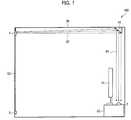
- FIG. 7is a schematic diagram illustrating an arrangement of a millimeter wave transceiving system of a second embodiment of the present invention.
- FIG. 8is a side view illustrating an arrangement of a reflecting plate of the millimeter wave transceiving system illustrated in FIG. 7 .
- FIG. 9is a schematic diagram illustrating an arrangement of a millimeter wave transceiving system of a third embodiment of the present invention.
- FIG. 9is a side view illustrating an arrangement of a reflecting plate illustrated in FIG. 9 .
- FIG. 10is a side view illustrating a modification of the arrangement.
- FIG. 11is a perspective view corresponding to (a) of FIG. 11 .
- FIG. 12is a schematic diagram illustrating an arrangement of an indoor wireless communications system, which is a first conventional example according to a conventional art.
- FIG. 13is a schematic diagram illustrating an arrangement of a reflecting mirror used in an optical space transmission system, which is a second conventional example according to a conventional art.
- FIG. 1is an arrangement example illustrating an overview of a millimeter wave transceiving system 100 .
- the millimeter wave transceiving system 100includes a transmitting apparatus 1 for transmitting an electric wave whose frequency falls in a millimeter waveband (hereinafter, the electric wave is referred to as millimeter wave), a reflecting plate 41 for reflecting a transmission signal (millimeter wave) transmitted from the transmitting apparatus 1 , and a receiving apparatus 2 for receiving a transmission signal (millimeter wave) reflected by the reflecting plate 41 .
- a transmitting apparatus 1for transmitting an electric wave whose frequency falls in a millimeter waveband
- the electric waveis referred to as millimeter wave
- a reflecting plate 41for reflecting a transmission signal (millimeter wave) transmitted from the transmitting apparatus 1
- a receiving apparatus 2for receiving a transmission signal (millimeter wave) reflected by the reflecting plate 41 .
- the present embodimentdescribes a millimeter wave video multiple transmission system, provided indoors, e.g., in a living room, which (i) upconverts a broadcast wave such as a digital broadcast wave so that the broadcast wave has a frequency in a 60 GHz frequency band and then (ii) transmits, as the transmission signal, the broadcast wave thus upconverted.
- a broadcast wavesuch as a digital broadcast wave
- the millimeter wave transceiving system 100is arranged as below.
- a transmission signal in a millimeter wave band transmitted from the transmitting apparatus 1is propagated via a transmission path 82 , and is then caused by the reflecting plate 41 to change its traveling angle vertically downward.
- the reflecting plate 41has a reflecting surface inclined by approximately 45° with respect to a ceiling 89 so as to reflect a transmission signal vertically downward.
- the transmission signal thus reflectedis propagated via a transmission path 81 , and then enters the receiving apparatus 2 which is mounted on a television rack (television stand) 32 so as to be behind a television 31 .
- the transmitting apparatus 1is provided on a wall near the ceiling 89 , and connected, via a coaxial cable 62 , to a level adjuster/power supply 5 , which is connected to an indoor terminal of a broadcast antenna.
- the level adjuster/power supply 5is connected, via the indoor terminal of broadcast antenna, to outdoor antennas such as a terrestrial broadcast receiving antenna and/or a satellite broadcast receiving antenna.
- the level adjuster/power supply 5properly (i) amplifies, to a level required by the transmitting apparatus 1 , a signal supplied via the indoor terminal of the broadcast antenna, and (ii) adds a DC (direct current) voltage of 15V required by the transmitting apparatus 1 to the signal thus amplified, so as to supply the signal to the transmitting apparatus 1 via the coaxial cable 62 .
- the transmitting apparatus 1is fixed by use of, e.g., a metal fixer so as to suspend in an indoor high position near the ceiling 89 .
- the transmitting apparatus 1can be installed on a wall supporting the ceiling 89 .
- the transmitting apparatus 1receives a signal supplied from the level adjuster/power supply 5 via the coaxial cable 62 , and converts the signal thus received into a transmission signal so as to supply the transmission signal to the reflecting plate 41 via the transmission path 82 .
- the reflecting plate 41is provided in the transmission path 82 so as to be on the ceiling 89 .
- the reflecting plate 41has a reflecting surface for reflecting a transmission signal transmitted from the transmitting apparatus 1 .
- the reflecting surface of the reflecting plate 41reflects, toward the receiving apparatus 2 via the transmission path 81 , a transmission signal transmitted from the transmitting apparatus 1 via the transmission path 82 .
- the receiving apparatus 2is provided, e.g., in the vicinity of the television 31 (display apparatus) or on the television rack 32 .
- the receiving apparatus 2receives a transmission signal reflected by the reflecting plate 41 , and supplies the transmission signal to the television 31 .
- the followingdescribes a concrete method for installing the transmitting apparatus 1 .
- the transmitting apparatus 1includes a directional transmitting antenna for receiving a millimeter wave.
- the transmitting apparatus 1is installed, in a position away from the ceiling 89 by approximately 15 cm, so that a direction in which the transmitting apparatus 1 for transmitting a millimeter wave emits a beam (i.e., a direction in which a millimeter wave is transmitted: the transmission path 82 ) becomes substantially parallel to the ceiling 89 .
- the directional transmitting antennapreferably has an angle of beam spread which is not less than that of a receiving antenna of the receiving apparatus 2 .
- the reason for thisis that the arrangement allows an easy installation etc. because the arrangement ensures irradiation of a beam on an entire surface of the reflecting plate 41 . This allows an increase in a degree of freedom for positional relations among the transmitting apparatus 1 , the reflecting plate 41 , and the receiving apparatus 2 .
- An angle of beam spread of the receiving antennacan be determined depending on an area of a reflecting surface 43 of the reflecting plate 41 .
- a distance between the transmitting apparatus 1 and the ceiling 89is preferably in a range from approximately 5 cm to approximately 15 cm. This makes it possible to greatly reduce an effect of reflection from the ceiling 89 itself.
- a transmission signal in a millimeter wave band transmitted from the transmitting apparatus 1is partially reflected from the ceiling 89 if the transmitting apparatus 1 is provided near the ceiling 89 .
- the transmission signal, in a millimeter wave band, which has been reflected from the ceiling 89 (reflected wave reflected from the ceiling 89 ) and (ii) the transmission signal, in a millimeter wave band, which has been transmitted, without being reflected from the ceiling 89 , from the transmitting apparatus 1 to the reflecting plate 41 (direct wave)can be reflected by the reflecting plate 41 , and are then received by the receiving apparatus 2 as a transmission signal (multipath signal) containing both the transmission signals (i) and (ii) thus reflected by the reflecting plate 41 .
- a phase of the reflected wave reflected by the ceiling 89which is a part of the transmission signal transmitted from the transmitting apparatus 1 , is inverted by 180°, as compared to the direct wave, due to reflection from the ceiling 89 . Accordingly, phases of the transmission signals incident on the reflecting plate 41 are not identical but greatly differ from each other even if incident angles of the respective transmission signals do not greatly differ from each other. Such transmission signals reflected by the reflecting plate 41 cause the receiving apparatus 2 to receive an electric wave affected by multipath fading. This causes a decrease in a reception quality MER (Measurement Error Rate) and/or a C/N (Carrier to Noise) ratio.
- MERMeasurement Error Rate
- C/NCarrier to Noise
- an undesired signali.e., a multipath signal which causes a noise is reflected by the reflecting plate 41 at such an angle that causes the receiving apparatus 2 not to receive the multipath signal.
- a multipath signalwhich causes a noise is reflected by the reflecting plate 41 at such an angle that causes the receiving apparatus 2 not to receive the multipath signal.
- the followingdescribes how to arrange and install the reflecting plate 41 , with reference to (a) and (b) of FIG. 2 , and (a) and (b) of FIG. 3 .
- FIG. 2is an explanatory view illustrating how the reflecting plate 41 is installed to the ceiling 89 .
- FIG. 2is a schematic diagram illustrating how the reflecting plate 41 is arranged.
- FIG. 3is a cross-sectional view illustrating a reflecting plate having a reflecting surface made of a metal foil or a metal film.
- FIG. 3is a cross-sectional view illustrating a reflecting plate having a reflecting surface made of a metal plate.
- the reflecting plate 41includes a first plate 47 having the reflecting surface 43 and a second plate 46 provided so as to incline with respect to the first plate 47 .
- the second plate 46is fixed to the ceiling 89 so that the reflecting plate 41 is installed on the ceiling 89 .
- the reflecting plate 41can further include a supporting plate 48 having a shape of a rectangular equilateral triangle so that an angle defined by the first plate 47 and the second plate 46 is fixed.
- the supporting plate 48is provided so as to be perpendicular to the first plate 47 and the second plate 46 , it becomes easy to secure accuracy of the angle defined by the first plate 47 and the second plate 46 and the angle scarcely changes over time. As such, it is possible to (i) stably fix the reflecting plate 41 to the ceiling 89 and (ii) secure a stable wireless transmission path.
- the reflecting plate 41can be replaced by a reflecting plate 41 a illustrated in (a) of FIG. 3 .
- a first plate 47 and a second plate 46both made of a sheet such as an expanded polystyrene sheet or a polypropylene sheet are bonded with the use of an adhesive or the like, and an aluminum tape is attached onto a reflecting surface 43 .
- the first plate 47 and the second plate 46can be easily prepared, for example, by bonding, with the use of an adhesive or the like, two expanded polystyrene sheets each having a thickness of few millimeters or two polypropylene sheets each having a thickness not more than 1 mm.
- the reflecting surface 43is prepared by attaching an aluminum tape onto the first plate 47 .
- An electrically conductive sheet 42is provided on a back surface (i.e., a side opposite to the reflecting surface 43 ) of the first plate 47 .
- the reflecting plate 41 acan be installed on the ceiling 89 by just fixing the second plate 46 on the ceiling 89 with the use of a tape or screws 44 .
- the angle defined by the first plate 47 and the second plate 46preferably is approximately 45°. This makes it possible to prevent a direction in which a millimeter wave is reflected by the reflecting plate 41 a from greatly deviating from a vertical downward direction, even if a horizontal angle of the reflecting plate 41 a is adjusted in a case where the reflecting plate 41 a is installed on, e.g., the ceiling 89 so that the second plate 46 of the reflecting plate 41 a becomes parallel with a horizontal plane.
- the reflecting plate 41can be replaced by a reflecting plate 41 b illustrated in (b) of FIG. 3 .
- a first plate 47 and a second plate 46are prepared by folding a single metal plate such as an aluminum plate.
- the reflecting plate 41 bcan be prepared by folding, at an angle of 45°, a flat aluminum plate having an area of 15 cm by 30 cm into a twofold one having an area of 15 cm by 15 cm.
- a sheetsuch as a thin piece of paper or a plastic sheet to which a design is subjected is further attached onto the first plate 47 of the reflecting plate 41 b made of an aluminum plate.
- a millimeter wavemostly passes through the sheet, and is then reflected by the aluminum plate.
- the reflecting plate 41( 41 a or 41 b ) is installed so that (i) the second plate 46 is parallel with a direction in which a transmission signal is transmitted via the transmission path 82 and (ii) the first plate 47 blocks the transmission path 82 .
- the first plate 47 and the second plate 46are connected at a tilt angle defined by them.
- the reflecting plate 41it is possible to install the reflecting plate 41 merely by (i) rotating the reflecting plate 41 only horizontally to adjust a rotation angle of the reflecting plate 41 so that the receiving apparatus 2 a receives a transmission signal having a maximum signal level or a maximum reception C/N ratio and (ii) fixing the reflecting plate 41 by use of a fixing member such as a tape or the screws 44 .
- a function of evaluating a signal level of or a reception C/N ratio of a transmission signalis usually provided, as a function of evaluating an antenna level, inside a television capable of receiving digital broadcast. Use of the function allows an adjustment of a rotation angle of the reflecting plate 41 .
- the reflecting plate 41thus eliminates the need for any difficult adjustment of a rotation angle because the reflecting plate 41 does not require a biaxial rotation function unlike a conventional reflecting mirror.
- FIG. 4is a view illustrating the receiving apparatus 2 mounted on the television rack 32 .
- (b) of FIG. 4is a view illustrating the receiving apparatus 2 provided on a surface of the television 31 .
- the receiving apparatus 2is provided (i) on a back surface side of the television 31 , i.e., on a side opposite to a side of a display screen (not illustrated) of the television 31 and (ii) on a horizontal surface of the television rack 32 .
- the reflecting plate 41is preferably provided such that a substantial center of the first plate 47 of the reflecting plate 41 is an extension of a vertical line extending from the receiving apparatus 2 .
- the receiving apparatus 2can be provided on a supporting shaft 34 which is perpendicularly provided on a base 33 of the television 31 (see (b) of FIG. 4 ).
- the television 31is, for example, a middle-sized or small-sized liquid crystal television
- the television 31has a swing function of rotating the display screen of the television 31 by rotating the display screen around the supporting shaft 34 which is perpendicularly extends.
- its supporting shaft 34can rotate by about ⁇ 20° in directions in which the liquid crystal television itself horizontally rotates around the supporting shaft 34 .
- the receiving apparatus 2is installed on the top surface of the supporting shaft 34 , around which the television 31 rotates, provided on the surface of the television 31 , no relative positional relation is changed between the receiving apparatus 2 and the reflecting plate 41 even if the display screen of the television 31 is rotated.
- the receiving apparatus 2can be installed anywhere, provided that the receiving apparatus 2 is provided on a back surface side of the large-sized slim television opposite to a display screen side of the large-sized slim television but is provided so that no obstacle exists between the receiving apparatus 2 and the reflecting plate 41 .
- a receiving apparatus 2can be installed on the top surface of the conventional CRT television.
- a receiving antenna 14 of the receiving apparatus 2is preferably a lens antenna made of dielectric.
- the lens antennahas a hemispherical shape. This makes it possible to reduce a frequency of blockage of a millimeter wave.
- the followingdescribes an area of the reflecting surface 43 of the reflecting plate 41 .
- the reflecting surface 43has an area, at a height h (distance), which is not more than an irradiated area of the receiving antenna 14 . That is, the area of the reflecting surface 43 is not more than an area in which the receiving antenna 14 receives a transmission signal. This makes it possible to secure reflection efficiency and prevent the reflecting plate 41 from increasing in its size. Accordingly, it is possible to save space on the ceiling 89 . In addition, a room appearance is less adversely affected.
- An irradiated area of the receiving antenna 14 of the receiving apparatus 2is indicated by (2h ⁇ tan ⁇ ) ⁇ (2h ⁇ tan ⁇ ).
- a longitudinal length of the reflecting surface 43is changed to ⁇ square root over ( 2 ) ⁇ (2h ⁇ tan ⁇ ).
- the reflecting surface 43has an area of ⁇ square root over ( 2 ) ⁇ (2h ⁇ tan ⁇ ) ⁇ (2h ⁇ tan ⁇ ).
- a preferable installation area for the reflecting plate 41is approximately an area of 21 cm by 30 cm in a case where h is 2 m and ⁇ is 3°.
- the reflecting plate 41 having an area of 21 cm by 30 cmis somewhat too large to be installed on the ceiling 89 .
- the reception energyusually includes a sufficient margin in view of a design of a regular communications line.
- a smallest area of the reflecting surface 43is equal to a square of a half wavelength of an operating frequency.
- the reflecting surface 43has difficulty in serving as a reflecting surface. Therefore, the reflecting plate 43 should have an area sufficiently larger than a square of a half wavelength of an operating frequency.
- the followingdescribes an arrangement example of the transmitting apparatus 1 and the receiving apparatus 2 , with reference to FIG. 5 .
- FIG. 5is a circuit diagram illustrating in detail how the millimeter wave transceiving system 100 is configured.
- the level adjuster/power supply 5is connected, via the indoor terminals for the broadcast antenna, to a terrestrial broadcast receiving antenna 10 a and a satellite broadcast receiving antenna 10 b which are provided outdoors.
- the level adjuster/power supply 5receives a signal fsa (wireless broadcast signal) of terrestrial broadcast as an input signal via the terrestrial broadcast receiving antenna 10 a .
- the level adjuster/power supply 5receives a signal fsb (wireless broadcast signal) of satellite broadcast wave via the satellite broadcast receiving antenna 10 b.
- Booster amplifiers 51 and 52 in the level adjuster/power supply 5appropriately amplify the signals fsa and fsb, respectively. Then, a connecting terminal 53 of the level adjuster/power supply 5 carries out combining and multiplexing with respect to the signals fsa and fsb thus amplified so that a multiplexed signal is supplied, as a single series signal fse (frequency: fse) to the transmitting apparatus 1 via the coaxial cable 62 (not illustrated in FIG. 5 ).
- the transmitting apparatus 1receives the single series of signal fse, as an input signal, from the level adjuster/power supply 5 .
- the single series signal fseis subjected to a level adjustment by an amplifier 203 , and is then supplied to a frequency mixer 201 .
- a reference signal source 20supplies a reference signal 71 c (frequency: fLO 1 ), is split into two by a connecting terminal 204 b .
- One of the two reference signals 71 c thus splitis supplied to the frequency mixer 201 (modulating means; modulator).
- the signal fsewhich has been supplied from the amplifier 203 and has been subjected to the level adjustment, is combined with the reference signal 71 c supplied from the connecting terminal 204 b , so as to be upconverted to a wireless signal 71 a (modulated signal) having an intermediate frequency (frequency: fIF 1 ).
- the wireless signal 71 a thus upconvertedis supplied to a connecting terminal 204 a , via a filter 202 a and the amplifier 203 .
- the other of the two reference signals 71 c split at the connecting terminal 204 bis supplied to the connecting terminal 204 a via a variable attenuator 95 .
- the wireless signal 71 a and the other one of the two reference signals 71 c thus splitare combined in the connecting terminal 204 a .
- the signal fse supplied to the transmitting apparatus 1is converted into and is then outputted from the connecting terminal 204 a as below.
- Wireless signal (signal): fLO 1 ⁇ fsefIF 1 (frequency)
- the intermediate frequency multiple signal 71 dis upconverted by the frequency mixer 301 , and is then filtered by a filter 302 so that only an upper sideband passes through the filter 302 .
- the upper sidebandis amplified by a millimeter wave power amplifier 303 , and is then transmitted, as a wireless multiple signal 72 , from the transmitting apparatus 1 via the transmitting antenna 4 .
- the transmission converter 3 a(i) upconverts the intermediate frequency multiplexed signal 71 d containing the wireless signal 71 a modulated by the frequency mixer 201 and the reference signal 71 c , (ii) amplifies the intermediate frequency multiple signal 71 d so as to obtain a millimeter wave, and (iii) transmits the millimeter wave as a wireless multiplexed signal 72 via the transmitting antenna 4 .
- the intermediate frequency multiplexed signal 71 dis converted by the transmission converter 3 a as below.
- Reference signal (signal): fLO 2+ fLO 1(2 m+ 1) fLO 1 (frequency)
- the signal fse supplied to the transmitting apparatus 1is eventually upconverted into the wireless multiple signal 72 containing (i) the reference signal whose frequency is (2m+1) times as high as the frequency fLO 1 of the reference signal 71 c , i.e., whose frequency is 11 times as high as the frequency fLO 1 and (ii) the wireless signal whose frequency is (2m+1) times as high as the frequency fLO 1 , i.e., whose frequency is 11 times as high as the frequency of the signal fse. Then, the wireless multiple signal 72 is transmitted via the transmitting antenna 4 .
- the wireless multiplexed signal 72 transmitted via the directional transmitting antenna 4 of the transmitting apparatus 1is received via the directional receiving antenna 14 as a wireless multiplexed signal 73 (transmission signal).
- the wireless multiplexed signal 73 thus receivedis supplied to a reception converter 11 .
- the wireless multiplexed signal 73is amplified by a low-noise amplifier 110 (amplification means), (ii) its image signal is suppressed by a band-pass filter 111 , (iii) its wireless signal [frequency: (2m+1)fLO 1 ⁇ fse] is downconverted by a two-terminal mixer 120 (downconversion means) in accordance with the reference signal [frequency: (2m+1)fLO 1 ] contained in the wireless multiple signal 73 , and (iv) a signal 74 a is then outputted from the reception converter 11 .
- a low-noise amplifier 110amplification means
- its image signalis suppressed by a band-pass filter 111
- its wireless signal [frequency: (2m+1)fLO 1 ⁇ fse]is downconverted by a two-terminal mixer 120 (downconversion means) in accordance with the reference signal [frequency: (2m+1)fLO 1 ] contained in the wireless multiple signal 73
- a signal 74 a
- a downconversion process carried out by the reception converter 11can be described as below. Specifically, the wireless multiple signal 73 supplied to the reception converter 11 is converted by the reception converter 11 into the signal 74 a as below.
- a signal fsecan be thus obtained as the signal 74 a supplied from the reception converter 11 .
- the signal 74 a thus downconvertedis obtained by decoding (demodulating) the single series of signal fse supplied to the transmitting apparatus 1 .
- the signal fse thus decodedhas nothing to do with a frequency deviation and phase noise characteristics of the reference signal 71 c (frequency: fLO 1 ) in the transmitting apparatus.
- the signal 74 a outputted from the reception converter 11is appropriately adjusted by a variable attenuator. Then, the signal 74 a passed through a filter is appropriately amplified by an amplifier 195 , and is then outputted as a signal 75 (signal fse) from the receiving apparatus 2 via a connecting terminal 196 and an output terminal 500 .
- the signal 75is supplied to the television 31 or an electronic device such as a video recorder.
- the transmitting apparatus 1 and the receiving apparatus 2each have a level detector 18 (detection means) which produces a sound, having a sound volume or tone, in accordance with a signal level (signal strength) of the signal fsa of terrestrial broadcast or a signal level of the signal fsb of satellite broadcast.
- a level detector 18detection means which produces a sound, having a sound volume or tone, in accordance with a signal level (signal strength) of the signal fsa of terrestrial broadcast or a signal level of the signal fsb of satellite broadcast.
- the present embodimentdeals with an arrangement in which the receiving apparatus 2 includes a level detector 18 .
- a switch 19 of the level detector 18is connected to the connecting terminal 196 . While the switch 19 is in an ON state, the signal 75 which is outputted to the output terminal 500 via the connecting terminal 196 is branched to the switch 19 .
- the signal 75 supplied to the switch 19is supplied to a beeper 9 via circuits such as a filter and an amplifier which are connected as needed to the switch 19 . This causes the beeper 9 to beep in accordance with a signal level of the signal 75 .
- position adjustment and direction adjustmentare required for the transmitting apparatus 1 , the reflecting plate 41 , and the receiving apparatus 2 .
- Some televisions 31have a function of indicating an antenna level. However, it is not always possible to allow a user to determine in real time, based only on such a function, whether or not the position adjustment and direction adjustment of the transmitting apparatus 1 and the reflecting plate 41 have been properly done. This is because the user can not always view a television screen while carrying out the position adjustment and direction adjustment.
- the receiving apparatus 2 and the transmitting apparatus 1includes a level detector 18 , it is possible to properly carry out position adjustment and direction adjustment of the transmitting apparatus 1 and the reflecting plate 41 with the aid of a function of notifying a user of a signal strength of a received signal by a sound volume or a tone of a sound of a beeper 9 of a level detector 18 .
- the switch 19is turned off (OFF) while the function of the beeper 9 is not used.
- the function of the beeper 9allows a user to check whether or not the transmitting apparatus 1 , the reflecting plate 41 , and the receiving apparatus 2 are in their proper positions even if the transmitting apparatus 1 , the reflecting plate 41 , and the receiving apparatus 2 are moved due to room cleaning or the like.
- the followingshows another example of respective circuit configurations of a transmitting apparatus 1 and a receiving apparatus 2 .
- FIG. 6is a circuit diagram illustrating how a millimeter wave transceiving system 100 is configured.
- the transmitting apparatus 1is the same as that of the detailed circuit configuration example 1 of the foregoing millimeter wave transceiving system 100 , except for a receiving apparatus 2 b .
- the receiving apparatus 2 bis different from the receiving apparatus 2 in that the receiving apparatus 2 b (i) generates a second intermediate frequency multiplexed signal 74 b by first downconverting a local oscillator signal 73 b (frequency: fLO 3 ) which is an output of a local oscillator 8 , and (ii) includes a reference signal regenerating/frequency converter circuit 12 as a second downconversion means.
- a frequency mixer 119(first downconversion means) is connected to a band-pass filter 111 .
- the frequency mixer 119is further connected to the local oscillator 8 .
- a wireless multiple signal 73 supplied to the reception converter 11 b via a receiving antenna 14is amplified by a low-noise amplifier 110 (amplification means).
- An image signal contained in the wireless multiple signal 73is removed by the band-pass filter 111 .
- the wireless multiplexed signal 73 from which the image signal is removedis downconverted by the frequency mixer 119 with the use of a local oscillator signal 73 b (frequency: fLO 3 ) supplied from the local oscillator 8 , and is then outputted from the frequency mixer 119 as a second intermediate frequency multiplexed signal 74 b.
- a process in which the wireless multiple signal 73 is downconverted into the second intermediate frequency multiple signal 74 bcan be described as below. Specifically, a reference signal and a wireless signal contained in the wireless multiplexed signal 73 supplied to the reception converter 11 b are converted into the intermediate frequency multiplexed signal 74 b as below.
- the receiving apparatus 2 bincludes a reference signal regenerating/frequency converter circuit 12 as a second downconverter.
- a second intermediate frequency multiplexed signal 74 outputted from the reception converter 11 bis supplied to the reference signal regenerating/frequency converter circuit 12 .
- the second intermediate frequency signal 74 b supplied to the reference signal regenerating/frequency converter circuit 12first passes through a filter 172 , is subjected to amplification and level adjustment by an intermediate frequency amplifier 159 , and is then split into two by the connecting terminal 161 .
- One of the two second intermediate frequency multiple signals 74 b thus splitis subjected to extraction and amplification of a reference signal by a band-path filter 171 and by an amplifier 180 , respectively.
- the reference signalis thus regenerated.
- the reference signal thus regenerated by the amplifier 180has a local oscillator frequency used in second downconversion. That is, the reference signal can be regarded as a pseudo local oscillator signal used in the second downconversion.
- the reference signal thus regeneratedis supplied to a frequency mixer 201 via a connecting terminal 181 .
- the other of the two second intermediate frequency signals 74 b thus split by the connecting terminal 161is subjected to a level adjustment, by a few decibels, by a variable attenuator 164 , and is then downconverted by the frequency mixer 201 in accordance with the reference signal thus regenerated.
- the single series of signal fseis thus decoded (demodulated).
- the series of single series signal fse thus decoded(i) is subjected to a level adjustment by a filter 175 connected to the frequency mixer 201 as needed, (ii) is appropriately amplified by an amplifier 195 to a proper output level, and (iii) is then outputted, as a signal 75 b (signal fse), from the receiving apparatus 2 b via an output terminal 500 .
- the signal 75 bis supplied to a television 31 or an electronic device such as a video recorder.
- a frequency conversionis carried out from an intermediate frequency band to a frequency band of the single series signal fse so that a signal supplied to the transmitting apparatus 1 is decoded in the receiving apparatus 2 b.
- a process of frequency conversion abovecan be described as below in which an intermediate frequency is converted to a frequency of the signal fse which is an original signal supplied to the transmitting apparatus 1 .
- the second intermediate frequency multiplexed signal 74 b supplied to the reference signal regenerating/frequency converter circuit 12is converted to a signal 75 b by the reference signal regenerating/frequency converter circuit 12 as below.
- the signal thus downconverted by the receiving apparatus 2 bis obtained by decoding the single series of signal fse supplied to the transmitting apparatus 1 .
- the signal fse thus decodedhas nothing to do with a frequency deviation and phase noise characteristics of the reference signal 71 c (frequency: fLO 1 ) in the transmitting apparatus 1 .
- the receiving apparatus 2 bis arranged so as to (1) cause the intermediate frequency amplifier 159 of the receiving apparatus 2 b to carry out amplification, (2) cause the band-path filter 171 and the amplifier 180 to carry out regeneration of a reference signal, and (3) cause the frequency mixer 201 to carry out a downconversion.
- the receiving apparatus 2 bis arranged so as to amplify and reproduce a reference signal. This makes it possible to obtain a higher reception CN (carrier to noise) characteristic, as compared to the receiving apparatus 2 . As a result, this allows a long transmission distance.
- the receiving apparatus 2 bit is not necessary for the transmitting apparatus 1 to strictly carry out power control of a reference signal. This brings about advantages such as a reduction in manufacturing cost of the transmitting apparatus 1 and expansion of the permissible range of levels of signals to be supplied to the transmitting apparatus 1 .
- the connecting terminal 181is connected to a level detector 18 .
- a reference signal regenerated by the band-path filter 171 and the amplifier 180is partially branched by the connecting terminal 181 to the switch 19 of the level detector 18 .
- the arrangementis made for a function of notifying a user, by a sound volume or tone of a beep of the beeper 9 in accordance with a signal level of a reference signal, of whether or not direction adjustment and position adjustment of the transmitting apparatus 1 and the reflecting plate 41 are properly done.
- the transmitting apparatus 1While the transmitting apparatus 1 is in an ON state, the transmitting apparatus 1 always transmits a reference signal having a frequency of (2m+1)fLO 1 to the receiving apparatus 2 b even if no input signal of a broadcast wave is supplied to the transmitting apparatus 1 .
- the reference signal (i)is solely downconverted by the frequency mixer 119 in accordance with a signal (local oscillator signal 73 b ), having a frequency of fLO 3 , which is supplied from the local oscillator 8 , (ii) is extracted, and (iii) is then subjected to a level detection, it is possible (a) to detect respective transmission losses generated in the transmitting apparatus 1 , the reflecting plate 41 , and the receiving apparatus 2 b , (b) to adjust respective positions and respective angles, in the horizontal plane, of the transmitting apparatus 1 , the reflecting plate 41 , and the receiving apparatus 2 b , and (iii) to minimize wireless transmission losses generated among the transmitting apparatus 1 , the reflecting plate 41 , and the receiving apparatus 2 b.
- the receiving apparatus 2 bthus makes it possible to minimize wireless transmission losses before a signal of a broadcast wave is supplied to the transmitting apparatus 1 . As a result, it is possible to efficiently dispose a wireless system. That is, it is possible to efficiently dispose the transmitting apparatus 1 , the reflecting plate 41 , and the receiving apparatus 2 b.
- FIG. 7is a schematic diagram illustrating how a millimeter wave transceiving system 200 is arranged in the second embodiment.
- FIG. 8is a side view illustrating how the reflecting plate illustrated in FIG. 7 is arranged.
- the first embodimentdescribes an example where the reflecting surface 43 of the reflecting plate 41 (reflecting plate 41 a or 41 b ) is a flat surface. Unlike the first embodiment, a reflecting surface 43 c of a reflecting plate 41 c of the second embodiment is a concave surface.
- the transmitting apparatus 1is fixed, with the use of a tripod 101 , on a top surface of a piece of fixture and furniture 102 such as a chest of drawers.
- a level adjuster/power supply 5is connected to an indoor terminal of a broadcast antenna via a coaxial cable 62 .
- the level adjuster/power supply 5is provided on an area of the top surface of the fixture and furniture 102 , on which area the tripod 101 is provided.
- the level adjuster/power supply 5 and the transmitting apparatus 1are also connected with each other via the coaxial cable 62 .
- the transmitting apparatus 1is provided approximately 15 cm away from a ceiling 89 .
- the fixture and furniture 102is not limited to the chest but can be a rack such as a bookshelf.
- the transmitting apparatus 1can be attached to a tip of a stand having a pole whose length is approximately 2 m (e.g., stand having a pole used as a floor lamp or the like). This realizes the following advantages. That is, the coaxial cable 62 can be concealed inside the pole, and the transmitting apparatus 1 can become easily installed (not illustrated).
- the reflecting surface 43 c of the reflecting plate 41 cis a concave surface.
- a focal length of the reflecting surface 43 c having a concave shapeis adjusted to a distance from the reflecting surface 43 c to the receiving apparatus 2 , i.e., to a height of approximately 45 cm of the television rack 32 (i.e., approximately 2 m from the ceiling 89 ).
- a diameter of curvature of the concave surface of the reflecting surface 43 cis 4 m, and the concave surface has a long focal length of 2 m. Accordingly, the reflecting surface 43 c serves as a concave mirror having a gentle curve.
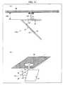
- FIG. 9is schematic diagram illustrating how a millimeter wave transceiving system 300 is arranged in the third embodiment.
- FIG. 10is a side view illustrating how a reflecting plate illustrated in FIG. 9 is arranged.
- (b) of FIG. 10is a side view illustrating a modification of the reflecting plate illustrated in FIG. 9 .
- the third embodimentis different from each of the first and second embodiments in the number and shape of the reflecting plate.
- a level adjuster/power supply 5is connected to an indoor terminal of a broadcast antenna.
- a transmitting apparatus 1is directly connected to the level adjuster/power supply 5 .
- Two reflecting plates 410i.e., reflecting plates 410 a and 410 b ) are provided in respective positions on a ceiling 89 .
- the reflecting plate 410 ais provided on the ceiling 89 so as to be directly above the transmitting apparatus 1 .
- the reflecting plate 410 bis provided on the ceiling 89 so as to face the reflecting plate 410 a .
- a receiving apparatus 2is provided so as to be directly below the reflecting plate 410 b .
- the receiving apparatus 2is provided on a horizontal surface of a television rack 32 so as to be behind a back surface of the television 31 .
- each of the reflecting plates 410has a third plate 400 (spacer).
- the third plate 400is provided between a first plate 47 and a second plate 46 so as to maintain a constant distance between the first plate 47 and the second plate 46 .
- the third plate 400is orthogonally connected to the second plate 46 , and connected to the first plate 47 so as to be inclined by 45° with respect to the first plate 47 . That is, the third plate 400 has perpendicular contact with the ceiling 89 since the second plate 46 is parallel with the ceiling 89 .
- the third plate 400causes a gap 442 to be secured between the reflecting surface 43 of the reflecting plate 410 and the ceiling 89 .
- the third plate 400preferably has a width of approximately 15 cm and a height falling in a range from approximately 5 cm to approximately 15 cm.
- the third plate 400causes the first plate 47 inclined by 45° with respect to the second plate 46 to shift downward by approximately 5 cm to 15 cm from the ceiling 89 .
- the first plate 47shifts downward by the gap 442 from the ceiling 89 . It follows that a transmission path 82 for a millimeter wave also shifts downward from the ceiling 89 . This makes it possible to reduce an adverse effect caused by a fluorescent lamp (ceiling light) 129 (see FIG. 9 ) or the like, which can be an obstacle for a millimeter wave and/or can cause scattering of a millimeter wave.
- a fluorescent lamp (ceiling light) 129see FIG. 9
- a thickness of the fluorescent lamp 129 to be attached on the ceiling 89is approximately 10 cm including a thickness of a plastic cover for a lamp.
- a metal fixer for the fluorescent lamp 129has a thickness falling in a range from approximately 5 cm to a little less than 10 cm.
- a transmitting antenna 4 of the transmitting apparatus 1has directivity (beam width) causing a transmitted beam to be radially diffused. Therefore, the presence of the fluorescent lamp 129 causes a relatively small effect of blockage of a transmission path of an electric wave even if the reflecting surface 43 , which is inclined by 45°, of the reflecting plate 41 is very close to the ceiling 89 , in the case of one-time reflection such as that shown in the first or second embodiment, i.e., in a case where the transmitting apparatus 1 is provided close to the ceiling 89 .
- the fluorescent lamp 129is likely to affect signal transmission. That is, an electric wave (millimeter wave) collides with the fluorescent lamp 129 in the case of the reflecting plate 41 or 41 b , which is used in the first and second embodiments. Accordingly, the electric wave is blocked and/or scattered by the reflecting plate 41 or 41 b . As a result, the transmission path 82 is disrupted, thereby deteriorating a state in which the transmission signal is propagated.
- an electric wavemillimeter wave
- the third plate 400is provided as is the case with the reflecting plate 410 , it is possible to reduce an adverse effect of blockage and/or scattering of a transmission signal by the fluorescent lamp 129 or the like, not only in the case of two-time reflection, but also in the case of one-time reflection.
- the reflecting plate 410is arranged so as to be made from a plastic material such as polystyrene or an acrylic material and (ii) an electrically conductive sheet 42 is formed only on the first plate 47 . This makes it possible to reduce an unnecessary reflection component.
- the third plate 400can be a transmitting surface in the case of a one-time reflection system or the like. This makes it possible to easily separate an electric wave into a reflected component and a transmitted component.
- a plurality of reflecting plates 410can be cascaded. As is the case with a reflecting plate 410 c illustrated in (b) of FIG. 10 , the reflecting plate 410 can be alternatively made by folding a single aluminum plate. This makes it possible to form the reflecting plate 410 more easily.
- the reflecting plate 410since the reflecting plate 410 has the third plate 400 , it is easy for a user to put his hand inside the reflecting plate 410 . This allows an easy installation and screw fixation of the reflecting plate 410 .
- the provision of the third plate 400secures the gap 442 of substantially 5 cm to substantially 15 cm between the ceiling 89 and the reflecting plate 410 . Accordingly, even if a millimeter wave once reflected at the ceiling 89 is reflected again by the reflecting plate 410 , an incident angle, with respect to the reflecting plate 410 , of a transmission signal propagated via the original transmission path 82 is different from an incident angle, with respect to the reflecting plate 410 , of the millimeter wave once reflected from the ceiling 89 . As a result, the millimeter wave thus reflected again from the reflecting plate 410 is propagated via a transmission path 81 b , whereas the original transmission signal thus reflected from the reflecting plate 410 is propagated via the transmission path 81 .
- a reflecting plate 410 ccan be arranged so that a supporting column 421 is provided via which a second plate 46 is connected to a ceiling 89 .
- FIG. 11is a side view illustrating the reflecting plate 410 c installed on the ceiling 89 via the supporting column 421 .
- (b) of FIG. 11is a perspective view illustrating the reflecting plate 410 c illustrated in (a) of FIG. 11 .
- each of (i) the reflecting plate 41 in the first and second embodiments and (ii) the reflecting plate 410 in the third embodimentcan be arranged so that a supporting column 421 is provided via which each of the second planes 46 is connected to the ceiling 89 .
- each of (i) the reflecting plate 41 of the first and second embodiments and (ii) the reflecting plate 410 of the third embodimentis arranged such that each of the second plates 46 is attached to a side wall and a corresponding one of the first plates serves as a reflecting surface which is inclined by a depression angle of 45°.
- the first plate 47 and the second plate 46 of the reflecting plate 41 close to the ceiling 89are provided so as to be at a depression angle of 45° with each other. This eliminates the need for adjustment of a depression angle, and it is necessary to merely adjust a horizontal angle. As a result, it becomes remarkably easy to adjust the reflecting plate 41 .
- the reflecting plate 41can be constituted by an aluminum plate having a thickness falling in a range from approximately 0.5 mm to approximately 1 mm.
- the reflecting plate 41can be constituted by attaching an aluminum tape onto an expanded polystyrene sheet having a thickness of a few millimeters or on a polypropylene sheet having a thickness of not more than 1 mm.
- the reflecting plate 41Since the arrangement realizes the reflecting plate 41 which is significantly light (i.e., the reflecting plate 41 has a weight comparable to that of a plastic sheet for a stationery use), the reflecting plate 41 can be easily installed, with the use of an attaching member such as a screw or a tape, on the ceiling 89 made of a gypsum board or a piece of plywood. This causes a reduction in a load on the ceiling 89 . As a result, part of the ceiling 89 hardly falls or peels off.
- the transmitting apparatus 1can be installed, without being inclined, so that a top surface of the transmitting apparatus 1 and the ceiling 89 are substantially parallel with each other in the vicinity of the ceiling 89 , although the transmitting apparatus 1 is installed in a somewhat high position. Therefore, it is possible to easily carry out a positioning of the transmitting apparatus 1 by using a level gauge, a plummet instrument, and the like.
- the millimeter wave transceiving system 100 of the present embodimentcan be also described as below.
- a millimeter wave transceiving systemis characterized in including: a millimeter wave transmitting apparatus, having a directional antenna, which is installed in an indoor high position; a reflecting plate having a metal plate or a metal sheet which has a depression angle of 45° with respect to a horizontal plane in the vicinity of a ceiling; and a millimeter wave receiving apparatus having a directional antenna directing toward the ceiling.
- the millimeter wave transceiving systemis characterized in that: the reflecting plate includes at least first and second plates which are at an angle of 45° with each other; the second plate is attached to the ceiling; and the first plate is a plate for reflecting a millimeter wave.
- the millimeter wave transceiving systemis characterized in that: the reflecting plate includes a third plate (i) which is at a right angle with the second plate and (ii) which is at an angle of 135° with the first plate, which is the plate for reflecting a millimeter wave.
- the millimeter wave transceiving systemis characterized in that: an area of the plate for reflecting a millimeter wave is not more than ⁇ square root over (2) ⁇ (2h ⁇ tan ⁇ ) ⁇ (2h ⁇ tan ⁇ ) where: h represents a distance between the receiving apparatus and the ceiling; and ⁇ represents a half bandwidth of a receiving antenna.
- the millimeter wave transceiving systemis characterized in that: an angle of beam spread of the directional antenna of the transmitting apparatus is not less than that of the directional antenna of the receiving apparatus.
- the millimeter wave transceiving systemis characterized in that the plate for reflecting a millimeter wave is a concave plate.
- the millimeter wave transceiving systemis characterized in that: the receiving apparatus is attached to a central part on a surface of a flat-screen television.
- the millimeter wave transceiving systemis characterized in that: the receiving apparatus is provided on a television stand or on a rack so that the directional antenna of the receiving apparatus has directivity in a vertical direction.
- the millimeter wave transceiving systemis characterized in that: the receiving apparatus is provided on a back side of a television.
- the millimeter wave transceiving systemis characterized in that: the directional antenna of the receiving apparatus is a lens antenna made of a dielectric.
- the millimeter wave transceiving systemis characterized in including that: a reference signal and a modulated signal are transmitted as a transmission wave via the directional antenna of the transmitting apparatus, received via the directional antenna of the receiving apparatus, amplified by an millimeter wave amplifier, and downconverted by a two-terminal mixer means in accordance with the reference signal thus amplified so that the received signal is demodulated into a broadcast signal and the broadcast signal thus demodulated is then transmitted to a receiving terminal.
- the millimeter wave transceiving systemis characterized in including that: a reference signal and a modulated signal are transmitted as a transmission wave via the directional antenna of the transmitting apparatus, received via the directional antenna of the receiving apparatus, amplified by an millimeter wave amplifier, downconverted by a millimeter wave mixer and a local oscillator, and downconverted by a mixer means in accordance with the reference signal thus amplified so that the received signal is demodulated into a broadcast signal and the broadcast signal thus demodulated is then transmitted to a receiving terminal.
- the millimeter wave transceiving systemis characterized in further including: detection means for (i) extracting a part of a signal received by the receiving apparatus, (ii) detecting a reception level of the part of the signal, and (iii) beeping at a sound volume or a tone in accordance with the reception level.
- the millimeter wave transceiving systemis characterized in that: a signal supplied to the transmitting apparatus is combined with a plurality of broadcast wave signals so as to be transmitted as a transmission wave via the directional antenna of the transmitting apparatus.
- a reflecting surface of a reflecting plate used in a millimeter wave transceiving system for transmitting and receiving a millimeter waveincludes a metal plate, a metal sheet, or a metal film. This realizes a lightweight reflecting plate, thereby allowing an easy installation of the millimeter wave transceiving system. Therefore, the reflecting plate of the present invention is suitably applicable particularly to a millimeter wave transceiving system used indoors.
Landscapes
- Physics & Mathematics (AREA)
- Electromagnetism (AREA)
- Optics & Photonics (AREA)
- Engineering & Computer Science (AREA)
- Computer Networks & Wireless Communication (AREA)
- Signal Processing (AREA)
- Aerials With Secondary Devices (AREA)
- Variable-Direction Aerials And Aerial Arrays (AREA)
- Radio Relay Systems (AREA)
- Radio Transmission System (AREA)
Abstract
Description
- 1 Transmitting apparatus
- 2 and2bReceiving apparatus
- 4 Transmitting antenna
- 5 Level adjuster/power supply
- 12 Reference signal regenerating/frequency converter circuit (second downconversion means)
- 14 Receiving antenna
- 18 Level detector (detection means)
- 31 Television (display apparatus)
- 32 Television rack
- 34 Supporting shaft
- 41,41a,41b, and41cReflecting plate
- 43 and43cReflecting surface
- 89 Ceiling
- 100,200, and300 Millimeter wave transceiving system
- 110 Low-noise amplifier (amplification means)
- 120 Two-terminal mixer (downconversion means)
- 201 Frequency mixer (modulation means)
Description of Embodiments
Reference signal (signal): fLO1 (frequency)
Wireless signal (signal):fLO1−fse=fIF1 (frequency)
Reference signal (signal):fLO2+fLO1=(2m+1)fLO1 (frequency)
Wireless signal (signal):fLO2+fIF1=fLO2+(fLO1−fse)=(2m+1)fLO1−fse(frequency)
[(2m+1)fLO1−fse]−[(2m+1)fLO1]=fse
[(2m+1)fLO1−fLO3]−[(2m+1)fLO1−fLO3−fse]=fse
Claims (15)
Applications Claiming Priority (2)
| Application Number | Priority Date | Filing Date | Title |
|---|---|---|---|
| JP2008-289927 | 2008-11-12 | ||
| JP2008289927AJP4708470B2 (en) | 2008-11-12 | 2008-11-12 | Millimeter wave transmission / reception system |
Publications (2)
| Publication Number | Publication Date |
|---|---|
| US20100119234A1 US20100119234A1 (en) | 2010-05-13 |
| US8412130B2true US8412130B2 (en) | 2013-04-02 |
Family
ID=42165293
Family Applications (1)
| Application Number | Title | Priority Date | Filing Date |
|---|---|---|---|
| US12/615,395Expired - Fee RelatedUS8412130B2 (en) | 2008-11-12 | 2009-11-10 | Millimeter wave transceiving system and reflecting plate |
Country Status (3)
| Country | Link |
|---|---|
| US (1) | US8412130B2 (en) |
| JP (1) | JP4708470B2 (en) |
| CN (1) | CN101741465B (en) |
Cited By (164)
| Publication number | Priority date | Publication date | Assignee | Title |
|---|---|---|---|---|
| US20130188674A1 (en)* | 2011-06-08 | 2013-07-25 | Naotake Yamamoto | Communication device and communication method |
| US20150162988A1 (en)* | 2013-12-10 | 2015-06-11 | At&T Intellectual Property I, L.P. | Quasi-optical coupler |
| US9119127B1 (en) | 2012-12-05 | 2015-08-25 | At&T Intellectual Property I, Lp | Backhaul link for distributed antenna system |
| US9154966B2 (en) | 2013-11-06 | 2015-10-06 | At&T Intellectual Property I, Lp | Surface-wave communications and methods thereof |
| US9312919B1 (en) | 2014-10-21 | 2016-04-12 | At&T Intellectual Property I, Lp | Transmission device with impairment compensation and methods for use therewith |
| US9461706B1 (en) | 2015-07-31 | 2016-10-04 | At&T Intellectual Property I, Lp | Method and apparatus for exchanging communication signals |
| US9490869B1 (en) | 2015-05-14 | 2016-11-08 | At&T Intellectual Property I, L.P. | Transmission medium having multiple cores and methods for use therewith |
| US9503189B2 (en) | 2014-10-10 | 2016-11-22 | At&T Intellectual Property I, L.P. | Method and apparatus for arranging communication sessions in a communication system |
| US9509415B1 (en) | 2015-06-25 | 2016-11-29 | At&T Intellectual Property I, L.P. | Methods and apparatus for inducing a fundamental wave mode on a transmission medium |
| US9520945B2 (en) | 2014-10-21 | 2016-12-13 | At&T Intellectual Property I, L.P. | Apparatus for providing communication services and methods thereof |
| US9525524B2 (en) | 2013-05-31 | 2016-12-20 | At&T Intellectual Property I, L.P. | Remote distributed antenna system |
| US9525210B2 (en) | 2014-10-21 | 2016-12-20 | At&T Intellectual Property I, L.P. | Guided-wave transmission device with non-fundamental mode propagation and methods for use therewith |
| US9531427B2 (en) | 2014-11-20 | 2016-12-27 | At&T Intellectual Property I, L.P. | Transmission device with mode division multiplexing and methods for use therewith |
| US9564947B2 (en) | 2014-10-21 | 2017-02-07 | At&T Intellectual Property I, L.P. | Guided-wave transmission device with diversity and methods for use therewith |
| US9577306B2 (en) | 2014-10-21 | 2017-02-21 | At&T Intellectual Property I, L.P. | Guided-wave transmission device and methods for use therewith |
| US9608740B2 (en) | 2015-07-15 | 2017-03-28 | At&T Intellectual Property I, L.P. | Method and apparatus for launching a wave mode that mitigates interference |
| US9608692B2 (en) | 2015-06-11 | 2017-03-28 | At&T Intellectual Property I, L.P. | Repeater and methods for use therewith |
| US9615269B2 (en) | 2014-10-02 | 2017-04-04 | At&T Intellectual Property I, L.P. | Method and apparatus that provides fault tolerance in a communication network |
| US9628116B2 (en) | 2015-07-14 | 2017-04-18 | At&T Intellectual Property I, L.P. | Apparatus and methods for transmitting wireless signals |
| US9628854B2 (en) | 2014-09-29 | 2017-04-18 | At&T Intellectual Property I, L.P. | Method and apparatus for distributing content in a communication network |
| US9640850B2 (en) | 2015-06-25 | 2017-05-02 | At&T Intellectual Property I, L.P. | Methods and apparatus for inducing a non-fundamental wave mode on a transmission medium |
| US9654173B2 (en) | 2014-11-20 | 2017-05-16 | At&T Intellectual Property I, L.P. | Apparatus for powering a communication device and methods thereof |
| US9653770B2 (en) | 2014-10-21 | 2017-05-16 | At&T Intellectual Property I, L.P. | Guided wave coupler, coupling module and methods for use therewith |
| US9667317B2 (en) | 2015-06-15 | 2017-05-30 | At&T Intellectual Property I, L.P. | Method and apparatus for providing security using network traffic adjustments |
| US9680670B2 (en) | 2014-11-20 | 2017-06-13 | At&T Intellectual Property I, L.P. | Transmission device with channel equalization and control and methods for use therewith |
| US9685992B2 (en) | 2014-10-03 | 2017-06-20 | At&T Intellectual Property I, L.P. | Circuit panel network and methods thereof |
| US9692101B2 (en) | 2014-08-26 | 2017-06-27 | At&T Intellectual Property I, L.P. | Guided wave couplers for coupling electromagnetic waves between a waveguide surface and a surface of a wire |
| US9705571B2 (en) | 2015-09-16 | 2017-07-11 | At&T Intellectual Property I, L.P. | Method and apparatus for use with a radio distributed antenna system |
| US9705561B2 (en) | 2015-04-24 | 2017-07-11 | At&T Intellectual Property I, L.P. | Directional coupling device and methods for use therewith |
| US9722318B2 (en) | 2015-07-14 | 2017-08-01 | At&T Intellectual Property I, L.P. | Method and apparatus for coupling an antenna to a device |
| US9729197B2 (en) | 2015-10-01 | 2017-08-08 | At&T Intellectual Property I, L.P. | Method and apparatus for communicating network management traffic over a network |
| US9735833B2 (en) | 2015-07-31 | 2017-08-15 | At&T Intellectual Property I, L.P. | Method and apparatus for communications management in a neighborhood network |
| US9742462B2 (en) | 2014-12-04 | 2017-08-22 | At&T Intellectual Property I, L.P. | Transmission medium and communication interfaces and methods for use therewith |
| US9749053B2 (en) | 2015-07-23 | 2017-08-29 | At&T Intellectual Property I, L.P. | Node device, repeater and methods for use therewith |
| US9749013B2 (en) | 2015-03-17 | 2017-08-29 | At&T Intellectual Property I, L.P. | Method and apparatus for reducing attenuation of electromagnetic waves guided by a transmission medium |
| US9748626B2 (en) | 2015-05-14 | 2017-08-29 | At&T Intellectual Property I, L.P. | Plurality of cables having different cross-sectional shapes which are bundled together to form a transmission medium |
| US9755697B2 (en) | 2014-09-15 | 2017-09-05 | At&T Intellectual Property I, L.P. | Method and apparatus for sensing a condition in a transmission medium of electromagnetic waves |
| US9762289B2 (en) | 2014-10-14 | 2017-09-12 | At&T Intellectual Property I, L.P. | Method and apparatus for transmitting or receiving signals in a transportation system |
| US9769020B2 (en) | 2014-10-21 | 2017-09-19 | At&T Intellectual Property I, L.P. | Method and apparatus for responding to events affecting communications in a communication network |
| US9769128B2 (en) | 2015-09-28 | 2017-09-19 | At&T Intellectual Property I, L.P. | Method and apparatus for encryption of communications over a network |
| US9780834B2 (en) | 2014-10-21 | 2017-10-03 | At&T Intellectual Property I, L.P. | Method and apparatus for transmitting electromagnetic waves |
| US9793951B2 (en) | 2015-07-15 | 2017-10-17 | At&T Intellectual Property I, L.P. | Method and apparatus for launching a wave mode that mitigates interference |
| US9793955B2 (en) | 2015-04-24 | 2017-10-17 | At&T Intellectual Property I, Lp | Passive electrical coupling device and methods for use therewith |
| US9793973B2 (en) | 2014-09-15 | 2017-10-17 | Samsung Electronics Co., Ltd. | Non-feeding reradiating repeater and method for manufacturing of the same |
| US9793954B2 (en) | 2015-04-28 | 2017-10-17 | At&T Intellectual Property I, L.P. | Magnetic coupling device and methods for use therewith |
| US20170302306A1 (en)* | 2015-04-17 | 2017-10-19 | Apple Inc. | Electronic Device With Millimeter Wave Antennas |
| US9800327B2 (en) | 2014-11-20 | 2017-10-24 | At&T Intellectual Property I, L.P. | Apparatus for controlling operations of a communication device and methods thereof |
| US9820146B2 (en) | 2015-06-12 | 2017-11-14 | At&T Intellectual Property I, L.P. | Method and apparatus for authentication and identity management of communicating devices |
| US9838896B1 (en) | 2016-12-09 | 2017-12-05 | At&T Intellectual Property I, L.P. | Method and apparatus for assessing network coverage |
| US9836957B2 (en) | 2015-07-14 | 2017-12-05 | At&T Intellectual Property I, L.P. | Method and apparatus for communicating with premises equipment |
| US9847566B2 (en) | 2015-07-14 | 2017-12-19 | At&T Intellectual Property I, L.P. | Method and apparatus for adjusting a field of a signal to mitigate interference |
| US9847850B2 (en) | 2014-10-14 | 2017-12-19 | At&T Intellectual Property I, L.P. | Method and apparatus for adjusting a mode of communication in a communication network |
| US9853342B2 (en) | 2015-07-14 | 2017-12-26 | At&T Intellectual Property I, L.P. | Dielectric transmission medium connector and methods for use therewith |
| US9860075B1 (en) | 2016-08-26 | 2018-01-02 | At&T Intellectual Property I, L.P. | Method and communication node for broadband distribution |
| US9865911B2 (en) | 2015-06-25 | 2018-01-09 | At&T Intellectual Property I, L.P. | Waveguide system for slot radiating first electromagnetic waves that are combined into a non-fundamental wave mode second electromagnetic wave on a transmission medium |
| US9866309B2 (en) | 2015-06-03 | 2018-01-09 | At&T Intellectual Property I, Lp | Host node device and methods for use therewith |
| US9871283B2 (en) | 2015-07-23 | 2018-01-16 | At&T Intellectual Property I, Lp | Transmission medium having a dielectric core comprised of plural members connected by a ball and socket configuration |
| US9871282B2 (en) | 2015-05-14 | 2018-01-16 | At&T Intellectual Property I, L.P. | At least one transmission medium having a dielectric surface that is covered at least in part by a second dielectric |
| US9876571B2 (en) | 2015-02-20 | 2018-01-23 | At&T Intellectual Property I, Lp | Guided-wave transmission device with non-fundamental mode propagation and methods for use therewith |
| US9876605B1 (en) | 2016-10-21 | 2018-01-23 | At&T Intellectual Property I, L.P. | Launcher and coupling system to support desired guided wave mode |
| US9876264B2 (en) | 2015-10-02 | 2018-01-23 | At&T Intellectual Property I, Lp | Communication system, guided wave switch and methods for use therewith |
| US9882257B2 (en) | 2015-07-14 | 2018-01-30 | At&T Intellectual Property I, L.P. | Method and apparatus for launching a wave mode that mitigates interference |
| US9882277B2 (en) | 2015-10-02 | 2018-01-30 | At&T Intellectual Property I, Lp | Communication device and antenna assembly with actuated gimbal mount |
| US9893795B1 (en) | 2016-12-07 | 2018-02-13 | At&T Intellectual Property I, Lp | Method and repeater for broadband distribution |
| US9904535B2 (en) | 2015-09-14 | 2018-02-27 | At&T Intellectual Property I, L.P. | Method and apparatus for distributing software |
| US9906269B2 (en) | 2014-09-17 | 2018-02-27 | At&T Intellectual Property I, L.P. | Monitoring and mitigating conditions in a communication network |
| US9912381B2 (en) | 2015-06-03 | 2018-03-06 | At&T Intellectual Property I, Lp | Network termination and methods for use therewith |
| US9912027B2 (en) | 2015-07-23 | 2018-03-06 | At&T Intellectual Property I, L.P. | Method and apparatus for exchanging communication signals |
| US9913139B2 (en) | 2015-06-09 | 2018-03-06 | At&T Intellectual Property I, L.P. | Signal fingerprinting for authentication of communicating devices |
| US9911020B1 (en) | 2016-12-08 | 2018-03-06 | At&T Intellectual Property I, L.P. | Method and apparatus for tracking via a radio frequency identification device |
| US9912419B1 (en) | 2016-08-24 | 2018-03-06 | At&T Intellectual Property I, L.P. | Method and apparatus for managing a fault in a distributed antenna system |
| US9917341B2 (en) | 2015-05-27 | 2018-03-13 | At&T Intellectual Property I, L.P. | Apparatus and method for launching electromagnetic waves and for modifying radial dimensions of the propagating electromagnetic waves |
| US9927517B1 (en) | 2016-12-06 | 2018-03-27 | At&T Intellectual Property I, L.P. | Apparatus and methods for sensing rainfall |
| US9948354B2 (en) | 2015-04-28 | 2018-04-17 | At&T Intellectual Property I, L.P. | Magnetic coupling device with reflective plate and methods for use therewith |
| US9948333B2 (en) | 2015-07-23 | 2018-04-17 | At&T Intellectual Property I, L.P. | Method and apparatus for wireless communications to mitigate interference |
| US9954287B2 (en) | 2014-11-20 | 2018-04-24 | At&T Intellectual Property I, L.P. | Apparatus for converting wireless signals and electromagnetic waves and methods thereof |
| US9967173B2 (en) | 2015-07-31 | 2018-05-08 | At&T Intellectual Property I, L.P. | Method and apparatus for authentication and identity management of communicating devices |
| US9973940B1 (en) | 2017-02-27 | 2018-05-15 | At&T Intellectual Property I, L.P. | Apparatus and methods for dynamic impedance matching of a guided wave launcher |
| US9991580B2 (en) | 2016-10-21 | 2018-06-05 | At&T Intellectual Property I, L.P. | Launcher and coupling system for guided wave mode cancellation |
| US9998870B1 (en) | 2016-12-08 | 2018-06-12 | At&T Intellectual Property I, L.P. | Method and apparatus for proximity sensing |
| US9999038B2 (en) | 2013-05-31 | 2018-06-12 | At&T Intellectual Property I, L.P. | Remote distributed antenna system |
| US9997819B2 (en) | 2015-06-09 | 2018-06-12 | At&T Intellectual Property I, L.P. | Transmission medium and method for facilitating propagation of electromagnetic waves via a core |
| US10009901B2 (en) | 2015-09-16 | 2018-06-26 | At&T Intellectual Property I, L.P. | Method, apparatus, and computer-readable storage medium for managing utilization of wireless resources between base stations |
| US10009067B2 (en) | 2014-12-04 | 2018-06-26 | At&T Intellectual Property I, L.P. | Method and apparatus for configuring a communication interface |
| US10009065B2 (en) | 2012-12-05 | 2018-06-26 | At&T Intellectual Property I, L.P. | Backhaul link for distributed antenna system |
| US10009063B2 (en) | 2015-09-16 | 2018-06-26 | At&T Intellectual Property I, L.P. | Method and apparatus for use with a radio distributed antenna system having an out-of-band reference signal |
| US10020587B2 (en) | 2015-07-31 | 2018-07-10 | At&T Intellectual Property I, L.P. | Radial antenna and methods for use therewith |
| US10020844B2 (en) | 2016-12-06 | 2018-07-10 | T&T Intellectual Property I, L.P. | Method and apparatus for broadcast communication via guided waves |
| US10027397B2 (en) | 2016-12-07 | 2018-07-17 | At&T Intellectual Property I, L.P. | Distributed antenna system and methods for use therewith |
| US10033107B2 (en) | 2015-07-14 | 2018-07-24 | At&T Intellectual Property I, L.P. | Method and apparatus for coupling an antenna to a device |
| US10033108B2 (en) | 2015-07-14 | 2018-07-24 | At&T Intellectual Property I, L.P. | Apparatus and methods for generating an electromagnetic wave having a wave mode that mitigates interference |
| US10044409B2 (en) | 2015-07-14 | 2018-08-07 | At&T Intellectual Property I, L.P. | Transmission medium and methods for use therewith |
| US10051483B2 (en) | 2015-10-16 | 2018-08-14 | At&T Intellectual Property I, L.P. | Method and apparatus for directing wireless signals |
| US10051629B2 (en) | 2015-09-16 | 2018-08-14 | At&T Intellectual Property I, L.P. | Method and apparatus for use with a radio distributed antenna system having an in-band reference signal |
| US10069535B2 (en) | 2016-12-08 | 2018-09-04 | At&T Intellectual Property I, L.P. | Apparatus and methods for launching electromagnetic waves having a certain electric field structure |
| US10074890B2 (en) | 2015-10-02 | 2018-09-11 | At&T Intellectual Property I, L.P. | Communication device and antenna with integrated light assembly |
| US10079661B2 (en) | 2015-09-16 | 2018-09-18 | At&T Intellectual Property I, L.P. | Method and apparatus for use with a radio distributed antenna system having a clock reference |
| US10090606B2 (en) | 2015-07-15 | 2018-10-02 | At&T Intellectual Property I, L.P. | Antenna system with dielectric array and methods for use therewith |
| US10090594B2 (en) | 2016-11-23 | 2018-10-02 | At&T Intellectual Property I, L.P. | Antenna system having structural configurations for assembly |
| US10103801B2 (en) | 2015-06-03 | 2018-10-16 | At&T Intellectual Property I, L.P. | Host node device and methods for use therewith |
| US10103422B2 (en) | 2016-12-08 | 2018-10-16 | At&T Intellectual Property I, L.P. | Method and apparatus for mounting network devices |
| US10135145B2 (en) | 2016-12-06 | 2018-11-20 | At&T Intellectual Property I, L.P. | Apparatus and methods for generating an electromagnetic wave along a transmission medium |
| US10135146B2 (en) | 2016-10-18 | 2018-11-20 | At&T Intellectual Property I, L.P. | Apparatus and methods for launching guided waves via circuits |
| US10135147B2 (en) | 2016-10-18 | 2018-11-20 | At&T Intellectual Property I, L.P. | Apparatus and methods for launching guided waves via an antenna |
| US10136434B2 (en) | 2015-09-16 | 2018-11-20 | At&T Intellectual Property I, L.P. | Method and apparatus for use with a radio distributed antenna system having an ultra-wideband control channel |
| US10142086B2 (en) | 2015-06-11 | 2018-11-27 | At&T Intellectual Property I, L.P. | Repeater and methods for use therewith |
| US10139820B2 (en) | 2016-12-07 | 2018-11-27 | At&T Intellectual Property I, L.P. | Method and apparatus for deploying equipment of a communication system |
| US10144036B2 (en) | 2015-01-30 | 2018-12-04 | At&T Intellectual Property I, L.P. | Method and apparatus for mitigating interference affecting a propagation of electromagnetic waves guided by a transmission medium |
| US10148016B2 (en) | 2015-07-14 | 2018-12-04 | At&T Intellectual Property I, L.P. | Apparatus and methods for communicating utilizing an antenna array |
| US10154493B2 (en) | 2015-06-03 | 2018-12-11 | At&T Intellectual Property I, L.P. | Network termination and methods for use therewith |
| US10170840B2 (en) | 2015-07-14 | 2019-01-01 | At&T Intellectual Property I, L.P. | Apparatus and methods for sending or receiving electromagnetic signals |
| US10168695B2 (en) | 2016-12-07 | 2019-01-01 | At&T Intellectual Property I, L.P. | Method and apparatus for controlling an unmanned aircraft |
| US10178445B2 (en) | 2016-11-23 | 2019-01-08 | At&T Intellectual Property I, L.P. | Methods, devices, and systems for load balancing between a plurality of waveguides |
| US10205655B2 (en) | 2015-07-14 | 2019-02-12 | At&T Intellectual Property I, L.P. | Apparatus and methods for communicating utilizing an antenna array and multiple communication paths |
| US10225025B2 (en) | 2016-11-03 | 2019-03-05 | At&T Intellectual Property I, L.P. | Method and apparatus for detecting a fault in a communication system |
| US10224634B2 (en) | 2016-11-03 | 2019-03-05 | At&T Intellectual Property I, L.P. | Methods and apparatus for adjusting an operational characteristic of an antenna |
| US10243784B2 (en) | 2014-11-20 | 2019-03-26 | At&T Intellectual Property I, L.P. | System for generating topology information and methods thereof |
| US10243270B2 (en) | 2016-12-07 | 2019-03-26 | At&T Intellectual Property I, L.P. | Beam adaptive multi-feed dielectric antenna system and methods for use therewith |
| US10264586B2 (en) | 2016-12-09 | 2019-04-16 | At&T Mobility Ii Llc | Cloud-based packet controller and methods for use therewith |
| US10291334B2 (en) | 2016-11-03 | 2019-05-14 | At&T Intellectual Property I, L.P. | System for detecting a fault in a communication system |
| US10291311B2 (en) | 2016-09-09 | 2019-05-14 | At&T Intellectual Property I, L.P. | Method and apparatus for mitigating a fault in a distributed antenna system |
| US10298293B2 (en) | 2017-03-13 | 2019-05-21 | At&T Intellectual Property I, L.P. | Apparatus of communication utilizing wireless network devices |
| US10305190B2 (en) | 2016-12-01 | 2019-05-28 | At&T Intellectual Property I, L.P. | Reflecting dielectric antenna system and methods for use therewith |
| US10312567B2 (en) | 2016-10-26 | 2019-06-04 | At&T Intellectual Property I, L.P. | Launcher with planar strip antenna and methods for use therewith |
| US10320586B2 (en) | 2015-07-14 | 2019-06-11 | At&T Intellectual Property I, L.P. | Apparatus and methods for generating non-interfering electromagnetic waves on an insulated transmission medium |
| US10326689B2 (en) | 2016-12-08 | 2019-06-18 | At&T Intellectual Property I, L.P. | Method and system for providing alternative communication paths |
| US10326494B2 (en) | 2016-12-06 | 2019-06-18 | At&T Intellectual Property I, L.P. | Apparatus for measurement de-embedding and methods for use therewith |
| US10340601B2 (en) | 2016-11-23 | 2019-07-02 | At&T Intellectual Property I, L.P. | Multi-antenna system and methods for use therewith |
| US10340603B2 (en) | 2016-11-23 | 2019-07-02 | At&T Intellectual Property I, L.P. | Antenna system having shielded structural configurations for assembly |
| US10340983B2 (en) | 2016-12-09 | 2019-07-02 | At&T Intellectual Property I, L.P. | Method and apparatus for surveying remote sites via guided wave communications |
| US10341142B2 (en) | 2015-07-14 | 2019-07-02 | At&T Intellectual Property I, L.P. | Apparatus and methods for generating non-interfering electromagnetic waves on an uninsulated conductor |
| US10340600B2 (en) | 2016-10-18 | 2019-07-02 | At&T Intellectual Property I, L.P. | Apparatus and methods for launching guided waves via plural waveguide systems |
| US10340573B2 (en) | 2016-10-26 | 2019-07-02 | At&T Intellectual Property I, L.P. | Launcher with cylindrical coupling device and methods for use therewith |
| US10348391B2 (en) | 2015-06-03 | 2019-07-09 | At&T Intellectual Property I, L.P. | Client node device with frequency conversion and methods for use therewith |
| US10355367B2 (en) | 2015-10-16 | 2019-07-16 | At&T Intellectual Property I, L.P. | Antenna structure for exchanging wireless signals |
| US10361489B2 (en) | 2016-12-01 | 2019-07-23 | At&T Intellectual Property I, L.P. | Dielectric dish antenna system and methods for use therewith |
| US10359749B2 (en) | 2016-12-07 | 2019-07-23 | At&T Intellectual Property I, L.P. | Method and apparatus for utilities management via guided wave communication |
| US10374316B2 (en) | 2016-10-21 | 2019-08-06 | At&T Intellectual Property I, L.P. | System and dielectric antenna with non-uniform dielectric |
| US10382976B2 (en) | 2016-12-06 | 2019-08-13 | At&T Intellectual Property I, L.P. | Method and apparatus for managing wireless communications based on communication paths and network device positions |
| US10389029B2 (en) | 2016-12-07 | 2019-08-20 | At&T Intellectual Property I, L.P. | Multi-feed dielectric antenna system with core selection and methods for use therewith |
| US10389037B2 (en) | 2016-12-08 | 2019-08-20 | At&T Intellectual Property I, L.P. | Apparatus and methods for selecting sections of an antenna array and use therewith |
| US10396887B2 (en) | 2015-06-03 | 2019-08-27 | At&T Intellectual Property I, L.P. | Client node device and methods for use therewith |
| US10411356B2 (en) | 2016-12-08 | 2019-09-10 | At&T Intellectual Property I, L.P. | Apparatus and methods for selectively targeting communication devices with an antenna array |
| US10439675B2 (en) | 2016-12-06 | 2019-10-08 | At&T Intellectual Property I, L.P. | Method and apparatus for repeating guided wave communication signals |
| US10446936B2 (en) | 2016-12-07 | 2019-10-15 | At&T Intellectual Property I, L.P. | Multi-feed dielectric antenna system and methods for use therewith |
| US10498044B2 (en) | 2016-11-03 | 2019-12-03 | At&T Intellectual Property I, L.P. | Apparatus for configuring a surface of an antenna |
| US10530505B2 (en) | 2016-12-08 | 2020-01-07 | At&T Intellectual Property I, L.P. | Apparatus and methods for launching electromagnetic waves along a transmission medium |
| US10535928B2 (en) | 2016-11-23 | 2020-01-14 | At&T Intellectual Property I, L.P. | Antenna system and methods for use therewith |
| US10547348B2 (en) | 2016-12-07 | 2020-01-28 | At&T Intellectual Property I, L.P. | Method and apparatus for switching transmission mediums in a communication system |
| US10601494B2 (en) | 2016-12-08 | 2020-03-24 | At&T Intellectual Property I, L.P. | Dual-band communication device and method for use therewith |
| US10637149B2 (en) | 2016-12-06 | 2020-04-28 | At&T Intellectual Property I, L.P. | Injection molded dielectric antenna and methods for use therewith |
| US10650940B2 (en) | 2015-05-15 | 2020-05-12 | At&T Intellectual Property I, L.P. | Transmission medium having a conductive material and methods for use therewith |
| US10665942B2 (en) | 2015-10-16 | 2020-05-26 | At&T Intellectual Property I, L.P. | Method and apparatus for adjusting wireless communications |
| US10679767B2 (en) | 2015-05-15 | 2020-06-09 | At&T Intellectual Property I, L.P. | Transmission medium having a conductive material and methods for use therewith |
| US10694379B2 (en) | 2016-12-06 | 2020-06-23 | At&T Intellectual Property I, L.P. | Waveguide system with device-based authentication and methods for use therewith |
| US10727599B2 (en) | 2016-12-06 | 2020-07-28 | At&T Intellectual Property I, L.P. | Launcher with slot antenna and methods for use therewith |
| US10755542B2 (en) | 2016-12-06 | 2020-08-25 | At&T Intellectual Property I, L.P. | Method and apparatus for surveillance via guided wave communication |
| US10777873B2 (en) | 2016-12-08 | 2020-09-15 | At&T Intellectual Property I, L.P. | Method and apparatus for mounting network devices |
| US10784670B2 (en) | 2015-07-23 | 2020-09-22 | At&T Intellectual Property I, L.P. | Antenna support for aligning an antenna |
| US10811767B2 (en) | 2016-10-21 | 2020-10-20 | At&T Intellectual Property I, L.P. | System and dielectric antenna with convex dielectric radome |
| US10819035B2 (en) | 2016-12-06 | 2020-10-27 | At&T Intellectual Property I, L.P. | Launcher with helical antenna and methods for use therewith |
| US10916969B2 (en) | 2016-12-08 | 2021-02-09 | At&T Intellectual Property I, L.P. | Method and apparatus for providing power using an inductive coupling |
| US10938108B2 (en) | 2016-12-08 | 2021-03-02 | At&T Intellectual Property I, L.P. | Frequency selective multi-feed dielectric antenna system and methods for use therewith |
| US11032819B2 (en) | 2016-09-15 | 2021-06-08 | At&T Intellectual Property I, L.P. | Method and apparatus for use with a radio distributed antenna system having a control channel reference signal |
Families Citing this family (198)
| Publication number | Priority date | Publication date | Assignee | Title |
|---|---|---|---|---|
| US8797211B2 (en)* | 2011-02-10 | 2014-08-05 | International Business Machines Corporation | Millimeter-wave communications using a reflector |
| CA3044757C (en) | 2011-10-21 | 2021-11-09 | Google Llc | User-friendly, network connected learning thermostat and related systems and methods |
| US9143000B2 (en) | 2012-07-06 | 2015-09-22 | Energous Corporation | Portable wireless charging pad |
| US10090886B1 (en) | 2014-07-14 | 2018-10-02 | Energous Corporation | System and method for enabling automatic charging schedules in a wireless power network to one or more devices |
| US9859756B2 (en) | 2012-07-06 | 2018-01-02 | Energous Corporation | Transmittersand methods for adjusting wireless power transmission based on information from receivers |
| US9368020B1 (en) | 2013-05-10 | 2016-06-14 | Energous Corporation | Off-premises alert system and method for wireless power receivers in a wireless power network |
| US10218227B2 (en) | 2014-05-07 | 2019-02-26 | Energous Corporation | Compact PIFA antenna |
| US9900057B2 (en) | 2012-07-06 | 2018-02-20 | Energous Corporation | Systems and methods for assigning groups of antenas of a wireless power transmitter to different wireless power receivers, and determining effective phases to use for wirelessly transmitting power using the assigned groups of antennas |
| US10224982B1 (en) | 2013-07-11 | 2019-03-05 | Energous Corporation | Wireless power transmitters for transmitting wireless power and tracking whether wireless power receivers are within authorized locations |
| US10186913B2 (en) | 2012-07-06 | 2019-01-22 | Energous Corporation | System and methods for pocket-forming based on constructive and destructive interferences to power one or more wireless power receivers using a wireless power transmitter including a plurality of antennas |
| US10090699B1 (en) | 2013-11-01 | 2018-10-02 | Energous Corporation | Wireless powered house |
| US9939864B1 (en) | 2014-08-21 | 2018-04-10 | Energous Corporation | System and method to control a wireless power transmission system by configuration of wireless power transmission control parameters |
| US9871398B1 (en) | 2013-07-01 | 2018-01-16 | Energous Corporation | Hybrid charging method for wireless power transmission based on pocket-forming |
| US10050462B1 (en) | 2013-08-06 | 2018-08-14 | Energous Corporation | Social power sharing for mobile devices based on pocket-forming |
| US9867062B1 (en) | 2014-07-21 | 2018-01-09 | Energous Corporation | System and methods for using a remote server to authorize a receiving device that has requested wireless power and to determine whether another receiving device should request wireless power in a wireless power transmission system |
| US9252628B2 (en) | 2013-05-10 | 2016-02-02 | Energous Corporation | Laptop computer as a transmitter for wireless charging |
| US10243414B1 (en) | 2014-05-07 | 2019-03-26 | Energous Corporation | Wearable device with wireless power and payload receiver |
| US9787103B1 (en) | 2013-08-06 | 2017-10-10 | Energous Corporation | Systems and methods for wirelessly delivering power to electronic devices that are unable to communicate with a transmitter |
| US10148097B1 (en) | 2013-11-08 | 2018-12-04 | Energous Corporation | Systems and methods for using a predetermined number of communication channels of a wireless power transmitter to communicate with different wireless power receivers |
| US11502551B2 (en) | 2012-07-06 | 2022-11-15 | Energous Corporation | Wirelessly charging multiple wireless-power receivers using different subsets of an antenna array to focus energy at different locations |
| US9941747B2 (en) | 2014-07-14 | 2018-04-10 | Energous Corporation | System and method for manually selecting and deselecting devices to charge in a wireless power network |
| US10199835B2 (en) | 2015-12-29 | 2019-02-05 | Energous Corporation | Radar motion detection using stepped frequency in wireless power transmission system |
| US10063106B2 (en) | 2014-05-23 | 2018-08-28 | Energous Corporation | System and method for a self-system analysis in a wireless power transmission network |
| US9887584B1 (en) | 2014-08-21 | 2018-02-06 | Energous Corporation | Systems and methods for a configuration web service to provide configuration of a wireless power transmitter within a wireless power transmission system |
| US9941754B2 (en) | 2012-07-06 | 2018-04-10 | Energous Corporation | Wireless power transmission with selective range |
| US9906065B2 (en) | 2012-07-06 | 2018-02-27 | Energous Corporation | Systems and methods of transmitting power transmission waves based on signals received at first and second subsets of a transmitter's antenna array |
| US10439448B2 (en) | 2014-08-21 | 2019-10-08 | Energous Corporation | Systems and methods for automatically testing the communication between wireless power transmitter and wireless power receiver |
| US10965164B2 (en) | 2012-07-06 | 2021-03-30 | Energous Corporation | Systems and methods of wirelessly delivering power to a receiver device |
| US10193396B1 (en) | 2014-05-07 | 2019-01-29 | Energous Corporation | Cluster management of transmitters in a wireless power transmission system |
| US10211674B1 (en) | 2013-06-12 | 2019-02-19 | Energous Corporation | Wireless charging using selected reflectors |
| US10141791B2 (en) | 2014-05-07 | 2018-11-27 | Energous Corporation | Systems and methods for controlling communications during wireless transmission of power using application programming interfaces |
| US9793758B2 (en) | 2014-05-23 | 2017-10-17 | Energous Corporation | Enhanced transmitter using frequency control for wireless power transmission |
| US10008889B2 (en) | 2014-08-21 | 2018-06-26 | Energous Corporation | Method for automatically testing the operational status of a wireless power receiver in a wireless power transmission system |
| US9876648B2 (en) | 2014-08-21 | 2018-01-23 | Energous Corporation | System and method to control a wireless power transmission system by configuration of wireless power transmission control parameters |
| US10206185B2 (en) | 2013-05-10 | 2019-02-12 | Energous Corporation | System and methods for wireless power transmission to an electronic device in accordance with user-defined restrictions |
| US9948135B2 (en) | 2015-09-22 | 2018-04-17 | Energous Corporation | Systems and methods for identifying sensitive objects in a wireless charging transmission field |
| US12057715B2 (en) | 2012-07-06 | 2024-08-06 | Energous Corporation | Systems and methods of wirelessly delivering power to a wireless-power receiver device in response to a change of orientation of the wireless-power receiver device |
| US9893555B1 (en) | 2013-10-10 | 2018-02-13 | Energous Corporation | Wireless charging of tools using a toolbox transmitter |
| US9954374B1 (en) | 2014-05-23 | 2018-04-24 | Energous Corporation | System and method for self-system analysis for detecting a fault in a wireless power transmission Network |
| US9812890B1 (en) | 2013-07-11 | 2017-11-07 | Energous Corporation | Portable wireless charging pad |
| US10063064B1 (en) | 2014-05-23 | 2018-08-28 | Energous Corporation | System and method for generating a power receiver identifier in a wireless power network |
| US9838083B2 (en) | 2014-07-21 | 2017-12-05 | Energous Corporation | Systems and methods for communication with remote management systems |
| US10992185B2 (en) | 2012-07-06 | 2021-04-27 | Energous Corporation | Systems and methods of using electromagnetic waves to wirelessly deliver power to game controllers |
| US10291055B1 (en) | 2014-12-29 | 2019-05-14 | Energous Corporation | Systems and methods for controlling far-field wireless power transmission based on battery power levels of a receiving device |
| US10038337B1 (en) | 2013-09-16 | 2018-07-31 | Energous Corporation | Wireless power supply for rescue devices |
| US10256657B2 (en) | 2015-12-24 | 2019-04-09 | Energous Corporation | Antenna having coaxial structure for near field wireless power charging |
| US9893768B2 (en) | 2012-07-06 | 2018-02-13 | Energous Corporation | Methodology for multiple pocket-forming |
| US9882427B2 (en) | 2013-05-10 | 2018-01-30 | Energous Corporation | Wireless power delivery using a base station to control operations of a plurality of wireless power transmitters |
| US10263432B1 (en) | 2013-06-25 | 2019-04-16 | Energous Corporation | Multi-mode transmitter with an antenna array for delivering wireless power and providing Wi-Fi access |
| US9843213B2 (en) | 2013-08-06 | 2017-12-12 | Energous Corporation | Social power sharing for mobile devices based on pocket-forming |
| US9859797B1 (en) | 2014-05-07 | 2018-01-02 | Energous Corporation | Synchronous rectifier design for wireless power receiver |
| US10063105B2 (en) | 2013-07-11 | 2018-08-28 | Energous Corporation | Proximity transmitters for wireless power charging systems |
| US10128693B2 (en) | 2014-07-14 | 2018-11-13 | Energous Corporation | System and method for providing health safety in a wireless power transmission system |
| US9973021B2 (en) | 2012-07-06 | 2018-05-15 | Energous Corporation | Receivers for wireless power transmission |
| US10128699B2 (en) | 2014-07-14 | 2018-11-13 | Energous Corporation | Systems and methods of providing wireless power using receiver device sensor inputs |
| US9991741B1 (en) | 2014-07-14 | 2018-06-05 | Energous Corporation | System for tracking and reporting status and usage information in a wireless power management system |
| US10075008B1 (en) | 2014-07-14 | 2018-09-11 | Energous Corporation | Systems and methods for manually adjusting when receiving electronic devices are scheduled to receive wirelessly delivered power from a wireless power transmitter in a wireless power network |
| US9887739B2 (en) | 2012-07-06 | 2018-02-06 | Energous Corporation | Systems and methods for wireless power transmission by comparing voltage levels associated with power waves transmitted by antennas of a plurality of antennas of a transmitter to determine appropriate phase adjustments for the power waves |
| US9876379B1 (en) | 2013-07-11 | 2018-01-23 | Energous Corporation | Wireless charging and powering of electronic devices in a vehicle |
| US10270261B2 (en) | 2015-09-16 | 2019-04-23 | Energous Corporation | Systems and methods of object detection in wireless power charging systems |
| US20140008993A1 (en) | 2012-07-06 | 2014-01-09 | DvineWave Inc. | Methodology for pocket-forming |
| US20140368048A1 (en)* | 2013-05-10 | 2014-12-18 | DvineWave Inc. | Wireless charging with reflectors |
| US9853692B1 (en) | 2014-05-23 | 2017-12-26 | Energous Corporation | Systems and methods for wireless power transmission |
| US9876394B1 (en) | 2014-05-07 | 2018-01-23 | Energous Corporation | Boost-charger-boost system for enhanced power delivery |
| US9843201B1 (en) | 2012-07-06 | 2017-12-12 | Energous Corporation | Wireless power transmitter that selects antenna sets for transmitting wireless power to a receiver based on location of the receiver, and methods of use thereof |
| US9831718B2 (en) | 2013-07-25 | 2017-11-28 | Energous Corporation | TV with integrated wireless power transmitter |
| US9899861B1 (en) | 2013-10-10 | 2018-02-20 | Energous Corporation | Wireless charging methods and systems for game controllers, based on pocket-forming |
| US9853458B1 (en) | 2014-05-07 | 2017-12-26 | Energous Corporation | Systems and methods for device and power receiver pairing |
| US9891669B2 (en) | 2014-08-21 | 2018-02-13 | Energous Corporation | Systems and methods for a configuration web service to provide configuration of a wireless power transmitter within a wireless power transmission system |
| US9824815B2 (en) | 2013-05-10 | 2017-11-21 | Energous Corporation | Wireless charging and powering of healthcare gadgets and sensors |
| US10992187B2 (en) | 2012-07-06 | 2021-04-27 | Energous Corporation | System and methods of using electromagnetic waves to wirelessly deliver power to electronic devices |
| US10199849B1 (en) | 2014-08-21 | 2019-02-05 | Energous Corporation | Method for automatically testing the operational status of a wireless power receiver in a wireless power transmission system |
| US10124754B1 (en) | 2013-07-19 | 2018-11-13 | Energous Corporation | Wireless charging and powering of electronic sensors in a vehicle |
| US10312715B2 (en) | 2015-09-16 | 2019-06-04 | Energous Corporation | Systems and methods for wireless power charging |
| US10141768B2 (en) | 2013-06-03 | 2018-11-27 | Energous Corporation | Systems and methods for maximizing wireless power transfer efficiency by instructing a user to change a receiver device's position |
| US9847677B1 (en) | 2013-10-10 | 2017-12-19 | Energous Corporation | Wireless charging and powering of healthcare gadgets and sensors |
| US9912199B2 (en) | 2012-07-06 | 2018-03-06 | Energous Corporation | Receivers for wireless power transmission |
| US9124125B2 (en) | 2013-05-10 | 2015-09-01 | Energous Corporation | Wireless power transmission with selective range |
| US9966765B1 (en) | 2013-06-25 | 2018-05-08 | Energous Corporation | Multi-mode transmitter |
| US9847679B2 (en) | 2014-05-07 | 2017-12-19 | Energous Corporation | System and method for controlling communication between wireless power transmitter managers |
| US9882430B1 (en) | 2014-05-07 | 2018-01-30 | Energous Corporation | Cluster management of transmitters in a wireless power transmission system |
| US9923386B1 (en) | 2012-07-06 | 2018-03-20 | Energous Corporation | Systems and methods for wireless power transmission by modifying a number of antenna elements used to transmit power waves to a receiver |
| US10230266B1 (en) | 2014-02-06 | 2019-03-12 | Energous Corporation | Wireless power receivers that communicate status data indicating wireless power transmission effectiveness with a transmitter using a built-in communications component of a mobile device, and methods of use thereof |
| US10381880B2 (en) | 2014-07-21 | 2019-08-13 | Energous Corporation | Integrated antenna structure arrays for wireless power transmission |
| US10223717B1 (en) | 2014-05-23 | 2019-03-05 | Energous Corporation | Systems and methods for payment-based authorization of wireless power transmission service |
| US9825674B1 (en) | 2014-05-23 | 2017-11-21 | Energous Corporation | Enhanced transmitter that selects configurations of antenna elements for performing wireless power transmission and receiving functions |
| US10291066B1 (en) | 2014-05-07 | 2019-05-14 | Energous Corporation | Power transmission control systems and methods |
| US10211680B2 (en) | 2013-07-19 | 2019-02-19 | Energous Corporation | Method for 3 dimensional pocket-forming |
| US9899873B2 (en) | 2014-05-23 | 2018-02-20 | Energous Corporation | System and method for generating a power receiver identifier in a wireless power network |
| US10211682B2 (en) | 2014-05-07 | 2019-02-19 | Energous Corporation | Systems and methods for controlling operation of a transmitter of a wireless power network based on user instructions received from an authenticated computing device powered or charged by a receiver of the wireless power network |
| US9859757B1 (en) | 2013-07-25 | 2018-01-02 | Energous Corporation | Antenna tile arrangements in electronic device enclosures |
| US9893554B2 (en) | 2014-07-14 | 2018-02-13 | Energous Corporation | System and method for providing health safety in a wireless power transmission system |
| US10224758B2 (en) | 2013-05-10 | 2019-03-05 | Energous Corporation | Wireless powering of electronic devices with selective delivery range |
| US9438045B1 (en) | 2013-05-10 | 2016-09-06 | Energous Corporation | Methods and systems for maximum power point transfer in receivers |
| US10205239B1 (en) | 2014-05-07 | 2019-02-12 | Energous Corporation | Compact PIFA antenna |
| US9806564B2 (en) | 2014-05-07 | 2017-10-31 | Energous Corporation | Integrated rectifier and boost converter for wireless power transmission |
| US20150326070A1 (en) | 2014-05-07 | 2015-11-12 | Energous Corporation | Methods and Systems for Maximum Power Point Transfer in Receivers |
| US10103582B2 (en) | 2012-07-06 | 2018-10-16 | Energous Corporation | Transmitters for wireless power transmission |
| US9728861B2 (en) | 2012-09-18 | 2017-08-08 | Nec Corporation | Reflector device, communication system using the same and communication method using the same |
| US9537357B2 (en) | 2013-05-10 | 2017-01-03 | Energous Corporation | Wireless sound charging methods and systems for game controllers, based on pocket-forming |
| US9538382B2 (en) | 2013-05-10 | 2017-01-03 | Energous Corporation | System and method for smart registration of wireless power receivers in a wireless power network |
| US9419443B2 (en) | 2013-05-10 | 2016-08-16 | Energous Corporation | Transducer sound arrangement for pocket-forming |
| US9866279B2 (en) | 2013-05-10 | 2018-01-09 | Energous Corporation | Systems and methods for selecting which power transmitter should deliver wireless power to a receiving device in a wireless power delivery network |
| US9819230B2 (en) | 2014-05-07 | 2017-11-14 | Energous Corporation | Enhanced receiver for wireless power transmission |
| US9843763B2 (en) | 2013-05-10 | 2017-12-12 | Energous Corporation | TV system with wireless power transmitter |
| US10103552B1 (en) | 2013-06-03 | 2018-10-16 | Energous Corporation | Protocols for authenticated wireless power transmission |
| US10003211B1 (en) | 2013-06-17 | 2018-06-19 | Energous Corporation | Battery life of portable electronic devices |
| JP6381182B2 (en)* | 2013-07-04 | 2018-08-29 | キヤノン株式会社 | Device with robot arm |
| US10021523B2 (en) | 2013-07-11 | 2018-07-10 | Energous Corporation | Proximity transmitters for wireless power charging systems |
| US9979440B1 (en) | 2013-07-25 | 2018-05-22 | Energous Corporation | Antenna tile arrangements configured to operate as one functional unit |
| FR3010836B1 (en) | 2013-09-18 | 2016-12-09 | Centre Nat Rech Scient | DEVICE FOR REFLECTING A WAVE, MOBILE DEVICE, AND SYSTEM |
| CN103760920B (en)* | 2014-01-23 | 2017-01-18 | 宏泰集团(厦门)有限公司 | Intelligent sound field control system |
| US10075017B2 (en) | 2014-02-06 | 2018-09-11 | Energous Corporation | External or internal wireless power receiver with spaced-apart antenna elements for charging or powering mobile devices using wirelessly delivered power |
| US9935482B1 (en) | 2014-02-06 | 2018-04-03 | Energous Corporation | Wireless power transmitters that transmit at determined times based on power availability and consumption at a receiving mobile device |
| US20150270624A1 (en)* | 2014-03-24 | 2015-09-24 | Srd Innovations Inc. | Rf wave bender |
| US10158257B2 (en) | 2014-05-01 | 2018-12-18 | Energous Corporation | System and methods for using sound waves to wirelessly deliver power to electronic devices |
| US9966784B2 (en) | 2014-06-03 | 2018-05-08 | Energous Corporation | Systems and methods for extending battery life of portable electronic devices charged by sound |
| US9800172B1 (en) | 2014-05-07 | 2017-10-24 | Energous Corporation | Integrated rectifier and boost converter for boosting voltage received from wireless power transmission waves |
| US10153653B1 (en) | 2014-05-07 | 2018-12-11 | Energous Corporation | Systems and methods for using application programming interfaces to control communications between a transmitter and a receiver |
| US10170917B1 (en) | 2014-05-07 | 2019-01-01 | Energous Corporation | Systems and methods for managing and controlling a wireless power network by establishing time intervals during which receivers communicate with a transmitter |
| US10153645B1 (en) | 2014-05-07 | 2018-12-11 | Energous Corporation | Systems and methods for designating a master power transmitter in a cluster of wireless power transmitters |
| US9973008B1 (en) | 2014-05-07 | 2018-05-15 | Energous Corporation | Wireless power receiver with boost converters directly coupled to a storage element |
| US9876536B1 (en) | 2014-05-23 | 2018-01-23 | Energous Corporation | Systems and methods for assigning groups of antennas to transmit wireless power to different wireless power receivers |
| US10116143B1 (en) | 2014-07-21 | 2018-10-30 | Energous Corporation | Integrated antenna arrays for wireless power transmission |
| US9871301B2 (en) | 2014-07-21 | 2018-01-16 | Energous Corporation | Integrated miniature PIFA with artificial magnetic conductor metamaterials |
| US10068703B1 (en) | 2014-07-21 | 2018-09-04 | Energous Corporation | Integrated miniature PIFA with artificial magnetic conductor metamaterials |
| CN106471674B (en) | 2014-07-31 | 2020-03-17 | 宇龙计算机通信科技(深圳)有限公司 | Same-frequency full-duplex antenna structure and electronic equipment for wireless communication |
| US9965009B1 (en) | 2014-08-21 | 2018-05-08 | Energous Corporation | Systems and methods for assigning a power receiver to individual power transmitters based on location of the power receiver |
| US9917477B1 (en) | 2014-08-21 | 2018-03-13 | Energous Corporation | Systems and methods for automatically testing the communication between power transmitter and wireless receiver |
| US10122415B2 (en) | 2014-12-27 | 2018-11-06 | Energous Corporation | Systems and methods for assigning a set of antennas of a wireless power transmitter to a wireless power receiver based on a location of the wireless power receiver |
| US9893535B2 (en) | 2015-02-13 | 2018-02-13 | Energous Corporation | Systems and methods for determining optimal charging positions to maximize efficiency of power received from wirelessly delivered sound wave energy |
| US9906275B2 (en) | 2015-09-15 | 2018-02-27 | Energous Corporation | Identifying receivers in a wireless charging transmission field |
| US10523033B2 (en) | 2015-09-15 | 2019-12-31 | Energous Corporation | Receiver devices configured to determine location within a transmission field |
| US12283828B2 (en) | 2015-09-15 | 2025-04-22 | Energous Corporation | Receiver devices configured to determine location within a transmission field |
| US10158259B1 (en) | 2015-09-16 | 2018-12-18 | Energous Corporation | Systems and methods for identifying receivers in a transmission field by transmitting exploratory power waves towards different segments of a transmission field |
| US9941752B2 (en) | 2015-09-16 | 2018-04-10 | Energous Corporation | Systems and methods of object detection in wireless power charging systems |
| US10778041B2 (en) | 2015-09-16 | 2020-09-15 | Energous Corporation | Systems and methods for generating power waves in a wireless power transmission system |
| US10008875B1 (en) | 2015-09-16 | 2018-06-26 | Energous Corporation | Wireless power transmitter configured to transmit power waves to a predicted location of a moving wireless power receiver |
| US10211685B2 (en) | 2015-09-16 | 2019-02-19 | Energous Corporation | Systems and methods for real or near real time wireless communications between a wireless power transmitter and a wireless power receiver |
| US9871387B1 (en) | 2015-09-16 | 2018-01-16 | Energous Corporation | Systems and methods of object detection using one or more video cameras in wireless power charging systems |
| US9893538B1 (en) | 2015-09-16 | 2018-02-13 | Energous Corporation | Systems and methods of object detection in wireless power charging systems |
| US10199850B2 (en) | 2015-09-16 | 2019-02-05 | Energous Corporation | Systems and methods for wirelessly transmitting power from a transmitter to a receiver by determining refined locations of the receiver in a segmented transmission field associated with the transmitter |
| US11710321B2 (en) | 2015-09-16 | 2023-07-25 | Energous Corporation | Systems and methods of object detection in wireless power charging systems |
| US10186893B2 (en) | 2015-09-16 | 2019-01-22 | Energous Corporation | Systems and methods for real time or near real time wireless communications between a wireless power transmitter and a wireless power receiver |
| US10027168B2 (en) | 2015-09-22 | 2018-07-17 | Energous Corporation | Systems and methods for generating and transmitting wireless power transmission waves using antennas having a spacing that is selected by the transmitter |
| US10128686B1 (en) | 2015-09-22 | 2018-11-13 | Energous Corporation | Systems and methods for identifying receiver locations using sensor technologies |
| US10153660B1 (en) | 2015-09-22 | 2018-12-11 | Energous Corporation | Systems and methods for preconfiguring sensor data for wireless charging systems |
| US10135295B2 (en) | 2015-09-22 | 2018-11-20 | Energous Corporation | Systems and methods for nullifying energy levels for wireless power transmission waves |
| US10020678B1 (en) | 2015-09-22 | 2018-07-10 | Energous Corporation | Systems and methods for selecting antennas to generate and transmit power transmission waves |
| US10135294B1 (en) | 2015-09-22 | 2018-11-20 | Energous Corporation | Systems and methods for preconfiguring transmission devices for power wave transmissions based on location data of one or more receivers |
| US10033222B1 (en) | 2015-09-22 | 2018-07-24 | Energous Corporation | Systems and methods for determining and generating a waveform for wireless power transmission waves |
| US10050470B1 (en) | 2015-09-22 | 2018-08-14 | Energous Corporation | Wireless power transmission device having antennas oriented in three dimensions |
| US10333332B1 (en) | 2015-10-13 | 2019-06-25 | Energous Corporation | Cross-polarized dipole antenna |
| US10734717B2 (en) | 2015-10-13 | 2020-08-04 | Energous Corporation | 3D ceramic mold antenna |
| US9853485B2 (en) | 2015-10-28 | 2017-12-26 | Energous Corporation | Antenna for wireless charging systems |
| US9899744B1 (en) | 2015-10-28 | 2018-02-20 | Energous Corporation | Antenna for wireless charging systems |
| US10063108B1 (en) | 2015-11-02 | 2018-08-28 | Energous Corporation | Stamped three-dimensional antenna |
| US10027180B1 (en) | 2015-11-02 | 2018-07-17 | Energous Corporation | 3D triple linear antenna that acts as heat sink |
| US10135112B1 (en) | 2015-11-02 | 2018-11-20 | Energous Corporation | 3D antenna mount |
| US10116162B2 (en) | 2015-12-24 | 2018-10-30 | Energous Corporation | Near field transmitters with harmonic filters for wireless power charging |
| US10027159B2 (en) | 2015-12-24 | 2018-07-17 | Energous Corporation | Antenna for transmitting wireless power signals |
| US10256677B2 (en) | 2016-12-12 | 2019-04-09 | Energous Corporation | Near-field RF charging pad with adaptive loading to efficiently charge an electronic device at any position on the pad |
| US10038332B1 (en) | 2015-12-24 | 2018-07-31 | Energous Corporation | Systems and methods of wireless power charging through multiple receiving devices |
| US10079515B2 (en) | 2016-12-12 | 2018-09-18 | Energous Corporation | Near-field RF charging pad with multi-band antenna element with adaptive loading to efficiently charge an electronic device at any position on the pad |
| US10320446B2 (en) | 2015-12-24 | 2019-06-11 | Energous Corporation | Miniaturized highly-efficient designs for near-field power transfer system |
| US11863001B2 (en) | 2015-12-24 | 2024-01-02 | Energous Corporation | Near-field antenna for wireless power transmission with antenna elements that follow meandering patterns |
| US10008886B2 (en) | 2015-12-29 | 2018-06-26 | Energous Corporation | Modular antennas with heat sinks in wireless power transmission systems |
| US10923954B2 (en) | 2016-11-03 | 2021-02-16 | Energous Corporation | Wireless power receiver with a synchronous rectifier |
| KR102185600B1 (en) | 2016-12-12 | 2020-12-03 | 에너저스 코포레이션 | A method of selectively activating antenna zones of a near field charging pad to maximize transmitted wireless power |
| US10680319B2 (en) | 2017-01-06 | 2020-06-09 | Energous Corporation | Devices and methods for reducing mutual coupling effects in wireless power transmission systems |
| US10389161B2 (en) | 2017-03-15 | 2019-08-20 | Energous Corporation | Surface mount dielectric antennas for wireless power transmitters |
| US10439442B2 (en) | 2017-01-24 | 2019-10-08 | Energous Corporation | Microstrip antennas for wireless power transmitters |
| US11011942B2 (en) | 2017-03-30 | 2021-05-18 | Energous Corporation | Flat antennas having two or more resonant frequencies for use in wireless power transmission systems |
| US10511097B2 (en) | 2017-05-12 | 2019-12-17 | Energous Corporation | Near-field antennas for accumulating energy at a near-field distance with minimal far-field gain |
| US11462949B2 (en) | 2017-05-16 | 2022-10-04 | Wireless electrical Grid LAN, WiGL Inc | Wireless charging method and system |
| US12074460B2 (en) | 2017-05-16 | 2024-08-27 | Wireless Electrical Grid Lan, Wigl Inc. | Rechargeable wireless power bank and method of using |
| US12074452B2 (en) | 2017-05-16 | 2024-08-27 | Wireless Electrical Grid Lan, Wigl Inc. | Networked wireless charging system |
| US10938116B2 (en)* | 2017-05-18 | 2021-03-02 | Samsung Electronics Co., Ltd. | Reflector for changing directionality of wireless communication beam and apparatus including the same |
| KR102347833B1 (en)* | 2017-05-18 | 2022-01-07 | 삼성전자 주식회사 | A reflector for changing the directionality of a wireless communication beam and an apparatus comprising thereof |
| US10848853B2 (en) | 2017-06-23 | 2020-11-24 | Energous Corporation | Systems, methods, and devices for utilizing a wire of a sound-producing device as an antenna for receipt of wirelessly delivered power |
| FR3069743B1 (en)* | 2017-07-28 | 2021-12-10 | Greenerwave | COMMUNICATION NETWORK ACCESS POINT, COMMUNICATION NETWORK, AND WIRELESS COMMUNICATION PROCESS |
| US10122219B1 (en) | 2017-10-10 | 2018-11-06 | Energous Corporation | Systems, methods, and devices for using a battery as a antenna for receiving wirelessly delivered power from radio frequency power waves |
| US11342798B2 (en) | 2017-10-30 | 2022-05-24 | Energous Corporation | Systems and methods for managing coexistence of wireless-power signals and data signals operating in a same frequency band |
| CN109747561A (en)* | 2017-11-01 | 2019-05-14 | 通用汽车环球科技运作有限责任公司 | The vehicle cabin of millimeter wave surface with optimization |
| JP6822388B2 (en)* | 2017-12-12 | 2021-01-27 | 日本製鉄株式会社 | Level measuring device |
| US10615647B2 (en) | 2018-02-02 | 2020-04-07 | Energous Corporation | Systems and methods for detecting wireless power receivers and other objects at a near-field charging pad |
| US11159057B2 (en) | 2018-03-14 | 2021-10-26 | Energous Corporation | Loop antennas with selectively-activated feeds to control propagation patterns of wireless power signals |
| US11515732B2 (en) | 2018-06-25 | 2022-11-29 | Energous Corporation | Power wave transmission techniques to focus wirelessly delivered power at a receiving device |
| CN109066092A (en)* | 2018-07-02 | 2018-12-21 | 南昌黑鲨科技有限公司 | A kind of terminal enclosure, terminal antenna and mobile terminal |
| US11437735B2 (en) | 2018-11-14 | 2022-09-06 | Energous Corporation | Systems for receiving electromagnetic energy using antennas that are minimally affected by the presence of the human body |
| US11539243B2 (en) | 2019-01-28 | 2022-12-27 | Energous Corporation | Systems and methods for miniaturized antenna for wireless power transmissions |
| EP3921945A1 (en) | 2019-02-06 | 2021-12-15 | Energous Corporation | Systems and methods of estimating optimal phases to use for individual antennas in an antenna array |
| TWI721880B (en) | 2020-05-04 | 2021-03-11 | 川升股份有限公司 | Dual-catr anechoic chamber and antenna measurement apparatus of the dual-catr anechoic chamber |
| US20230412236A1 (en) | 2020-10-22 | 2023-12-21 | Telefonaktiebolaget Lm Ericsson (Publ) | Proactive Link Blockage Avoidance for Reliable mmWave Communication |
| EP4239800A4 (en) | 2020-10-28 | 2024-04-24 | Sumitomo Electric Industries, Ltd. | REFLECTION UNIT AND WIRELESS TRANSMISSION SYSTEM |
| CN114465650B (en)* | 2020-11-10 | 2023-07-21 | 维沃移动通信有限公司 | wireless auxiliary device |
| JP7482100B2 (en)* | 2021-12-09 | 2024-05-13 | キヤノン株式会社 | Radiation detection equipment |
| JPWO2024142434A1 (en)* | 2022-12-27 | 2024-07-04 |
Citations (19)
| Publication number | Priority date | Publication date | Assignee | Title |
|---|---|---|---|---|
| US5091730A (en)* | 1983-10-31 | 1992-02-25 | Raytheon Company | Pulse radar and components therefor |
| US5184136A (en)* | 1983-10-31 | 1993-02-02 | Raytheon Company | Pulse radar and components therefor |
| JPH05206946A (en) | 1992-01-24 | 1993-08-13 | Matsushita Electric Works Ltd | Optical communication system |
| JPH06200584A (en) | 1993-01-06 | 1994-07-19 | Miri Ueibu:Kk | Electric wave reflector |
| JPH08223172A (en) | 1995-02-15 | 1996-08-30 | Mitsubishi Electric Corp | Wireless communication system |
| JPH08288901A (en) | 1995-04-10 | 1996-11-01 | Nippon Telegr & Teleph Corp <Ntt> | Wireless communication method |
| JPH0951293A (en) | 1995-05-30 | 1997-02-18 | Matsushita Electric Ind Co Ltd | Indoor wireless communication system |
| US5890055A (en)* | 1995-07-28 | 1999-03-30 | Lucent Technologies Inc. | Method and system for connecting cells and microcells in a wireless communications network |
| JP2002246832A (en) | 2001-02-15 | 2002-08-30 | Matsushita Electric Ind Co Ltd | Communication device |
| JP2005210632A (en) | 2004-01-26 | 2005-08-04 | Sharp Corp | Broadcast wave transmitting apparatus and broadcast wave receiving system |
| JP2005244362A (en) | 2004-02-24 | 2005-09-08 | Sony Corp | Millimeter wave communication system, millimeter wave transmitter, and millimeter wave receiver |
| US7020890B1 (en)* | 1999-04-05 | 2006-03-28 | Sharp Kabushiki Kaisha | Millimeter wave transmitter, millimeter wave receiver and millimeter wave communication system enabling simplification of wiring and improvement in degree of freedom for setting receiver in receiving system for terrestrial broadcasting and satellite broadcasting |
| US7046959B2 (en)* | 2002-09-05 | 2006-05-16 | Xytrans, Inc. | MMIC transceiver and low cost subharmonically driven microwave receiver |
| US7164932B1 (en)* | 1998-09-22 | 2007-01-16 | Sharp Kabushiki Kaisha | Millimeter band signal transmitting/receiving system having function of transmitting/receiving millimeter band signal and house provided with the same |
| US7206591B2 (en)* | 2003-08-13 | 2007-04-17 | Xytrans, Inc. | Toneless telemetry in a wireless system |
| WO2007136290A1 (en) | 2006-05-23 | 2007-11-29 | Intel Corporation | Millimeter-wave communication system with directional antenna and one or more millimeter-wave reflectors |
| US20090029648A1 (en)* | 2007-07-25 | 2009-01-29 | Sony Corporation | Information communication method, information communication system, information reception apparatus, and information transmission apparatus |
| US20090202088A1 (en)* | 2004-09-16 | 2009-08-13 | Seiko Epson Corporation | Ultrasonic transducer, ultrasonic speaker, acoustic system, and control method of ultrasonic transducer |
| US20120206299A1 (en)* | 2011-02-10 | 2012-08-16 | International Business Machines Corporation | Millimeter-wave communications using a reflector |
- 2008
- 2008-11-12JPJP2008289927Apatent/JP4708470B2/ennot_activeExpired - Fee Related
- 2009
- 2009-11-06CNCN200910220867.7Apatent/CN101741465B/ennot_activeExpired - Fee Related
- 2009-11-10USUS12/615,395patent/US8412130B2/ennot_activeExpired - Fee Related
Patent Citations (21)
| Publication number | Priority date | Publication date | Assignee | Title |
|---|---|---|---|---|
| US5091730A (en)* | 1983-10-31 | 1992-02-25 | Raytheon Company | Pulse radar and components therefor |
| US5184136A (en)* | 1983-10-31 | 1993-02-02 | Raytheon Company | Pulse radar and components therefor |
| JPH05206946A (en) | 1992-01-24 | 1993-08-13 | Matsushita Electric Works Ltd | Optical communication system |
| JPH06200584A (en) | 1993-01-06 | 1994-07-19 | Miri Ueibu:Kk | Electric wave reflector |
| JPH08223172A (en) | 1995-02-15 | 1996-08-30 | Mitsubishi Electric Corp | Wireless communication system |
| JPH08288901A (en) | 1995-04-10 | 1996-11-01 | Nippon Telegr & Teleph Corp <Ntt> | Wireless communication method |
| JPH0951293A (en) | 1995-05-30 | 1997-02-18 | Matsushita Electric Ind Co Ltd | Indoor wireless communication system |
| US5697063A (en) | 1995-05-30 | 1997-12-09 | Matsushita Electric Industrial Co., Ltd. | Indoor radio communication system |
| US5890055A (en)* | 1995-07-28 | 1999-03-30 | Lucent Technologies Inc. | Method and system for connecting cells and microcells in a wireless communications network |
| US7164932B1 (en)* | 1998-09-22 | 2007-01-16 | Sharp Kabushiki Kaisha | Millimeter band signal transmitting/receiving system having function of transmitting/receiving millimeter band signal and house provided with the same |
| US7020890B1 (en)* | 1999-04-05 | 2006-03-28 | Sharp Kabushiki Kaisha | Millimeter wave transmitter, millimeter wave receiver and millimeter wave communication system enabling simplification of wiring and improvement in degree of freedom for setting receiver in receiving system for terrestrial broadcasting and satellite broadcasting |
| JP2002246832A (en) | 2001-02-15 | 2002-08-30 | Matsushita Electric Ind Co Ltd | Communication device |
| US7046959B2 (en)* | 2002-09-05 | 2006-05-16 | Xytrans, Inc. | MMIC transceiver and low cost subharmonically driven microwave receiver |
| US7076201B2 (en)* | 2002-09-05 | 2006-07-11 | Xytrans, Inc. | Low cost VSAT MMIC transceiver with automatic power control |
| US7206591B2 (en)* | 2003-08-13 | 2007-04-17 | Xytrans, Inc. | Toneless telemetry in a wireless system |
| JP2005210632A (en) | 2004-01-26 | 2005-08-04 | Sharp Corp | Broadcast wave transmitting apparatus and broadcast wave receiving system |
| JP2005244362A (en) | 2004-02-24 | 2005-09-08 | Sony Corp | Millimeter wave communication system, millimeter wave transmitter, and millimeter wave receiver |
| US20090202088A1 (en)* | 2004-09-16 | 2009-08-13 | Seiko Epson Corporation | Ultrasonic transducer, ultrasonic speaker, acoustic system, and control method of ultrasonic transducer |
| WO2007136290A1 (en) | 2006-05-23 | 2007-11-29 | Intel Corporation | Millimeter-wave communication system with directional antenna and one or more millimeter-wave reflectors |
| US20090029648A1 (en)* | 2007-07-25 | 2009-01-29 | Sony Corporation | Information communication method, information communication system, information reception apparatus, and information transmission apparatus |
| US20120206299A1 (en)* | 2011-02-10 | 2012-08-16 | International Business Machines Corporation | Millimeter-wave communications using a reflector |
Cited By (231)
| Publication number | Priority date | Publication date | Assignee | Title |
|---|---|---|---|---|
| US20130188674A1 (en)* | 2011-06-08 | 2013-07-25 | Naotake Yamamoto | Communication device and communication method |
| US9191078B2 (en)* | 2011-06-08 | 2015-11-17 | Panasonic Intellectual Property Management Co., Ltd. | Communication device and communication method |
| US10009065B2 (en) | 2012-12-05 | 2018-06-26 | At&T Intellectual Property I, L.P. | Backhaul link for distributed antenna system |
| US9119127B1 (en) | 2012-12-05 | 2015-08-25 | At&T Intellectual Property I, Lp | Backhaul link for distributed antenna system |
| US10194437B2 (en) | 2012-12-05 | 2019-01-29 | At&T Intellectual Property I, L.P. | Backhaul link for distributed antenna system |
| US9699785B2 (en) | 2012-12-05 | 2017-07-04 | At&T Intellectual Property I, L.P. | Backhaul link for distributed antenna system |
| US9788326B2 (en) | 2012-12-05 | 2017-10-10 | At&T Intellectual Property I, L.P. | Backhaul link for distributed antenna system |
| US9999038B2 (en) | 2013-05-31 | 2018-06-12 | At&T Intellectual Property I, L.P. | Remote distributed antenna system |
| US10091787B2 (en) | 2013-05-31 | 2018-10-02 | At&T Intellectual Property I, L.P. | Remote distributed antenna system |
| US9930668B2 (en) | 2013-05-31 | 2018-03-27 | At&T Intellectual Property I, L.P. | Remote distributed antenna system |
| US10051630B2 (en) | 2013-05-31 | 2018-08-14 | At&T Intellectual Property I, L.P. | Remote distributed antenna system |
| US9525524B2 (en) | 2013-05-31 | 2016-12-20 | At&T Intellectual Property I, L.P. | Remote distributed antenna system |
| US9661505B2 (en) | 2013-11-06 | 2017-05-23 | At&T Intellectual Property I, L.P. | Surface-wave communications and methods thereof |
| US9467870B2 (en) | 2013-11-06 | 2016-10-11 | At&T Intellectual Property I, L.P. | Surface-wave communications and methods thereof |
| US9674711B2 (en) | 2013-11-06 | 2017-06-06 | At&T Intellectual Property I, L.P. | Surface-wave communications and methods thereof |
| US9154966B2 (en) | 2013-11-06 | 2015-10-06 | At&T Intellectual Property I, Lp | Surface-wave communications and methods thereof |
| US9479266B2 (en)* | 2013-12-10 | 2016-10-25 | At&T Intellectual Property I, L.P. | Quasi-optical coupler |
| US9876584B2 (en)* | 2013-12-10 | 2018-01-23 | At&T Intellectual Property I, L.P. | Quasi-optical coupler |
| US9794003B2 (en)* | 2013-12-10 | 2017-10-17 | At&T Intellectual Property I, L.P. | Quasi-optical coupler |
| US20150162988A1 (en)* | 2013-12-10 | 2015-06-11 | At&T Intellectual Property I, L.P. | Quasi-optical coupler |
| US10505642B2 (en) | 2013-12-10 | 2019-12-10 | At&T Intellectual Property I, L.P. | Quasi-optical coupler |
| US20160285512A1 (en)* | 2013-12-10 | 2016-09-29 | At&T Intellectual Property I, Lp | Quasi-optical coupler |
| US20180013498A1 (en)* | 2013-12-10 | 2018-01-11 | At&T Intellectual Property I, L.P. | Quasi-optical coupler |
| US9209902B2 (en)* | 2013-12-10 | 2015-12-08 | At&T Intellectual Property I, L.P. | Quasi-optical coupler |
| US10103819B2 (en)* | 2013-12-10 | 2018-10-16 | At&T Intellectual Property I, L.P. | Quasi-optical coupler |
| US9692101B2 (en) | 2014-08-26 | 2017-06-27 | At&T Intellectual Property I, L.P. | Guided wave couplers for coupling electromagnetic waves between a waveguide surface and a surface of a wire |
| US10096881B2 (en) | 2014-08-26 | 2018-10-09 | At&T Intellectual Property I, L.P. | Guided wave couplers for coupling electromagnetic waves to an outer surface of a transmission medium |
| US9793973B2 (en) | 2014-09-15 | 2017-10-17 | Samsung Electronics Co., Ltd. | Non-feeding reradiating repeater and method for manufacturing of the same |
| US9755697B2 (en) | 2014-09-15 | 2017-09-05 | At&T Intellectual Property I, L.P. | Method and apparatus for sensing a condition in a transmission medium of electromagnetic waves |
| US9768833B2 (en) | 2014-09-15 | 2017-09-19 | At&T Intellectual Property I, L.P. | Method and apparatus for sensing a condition in a transmission medium of electromagnetic waves |
| US10063280B2 (en) | 2014-09-17 | 2018-08-28 | At&T Intellectual Property I, L.P. | Monitoring and mitigating conditions in a communication network |
| US9906269B2 (en) | 2014-09-17 | 2018-02-27 | At&T Intellectual Property I, L.P. | Monitoring and mitigating conditions in a communication network |
| US9628854B2 (en) | 2014-09-29 | 2017-04-18 | At&T Intellectual Property I, L.P. | Method and apparatus for distributing content in a communication network |
| US9998932B2 (en) | 2014-10-02 | 2018-06-12 | At&T Intellectual Property I, L.P. | Method and apparatus that provides fault tolerance in a communication network |
| US9973416B2 (en) | 2014-10-02 | 2018-05-15 | At&T Intellectual Property I, L.P. | Method and apparatus that provides fault tolerance in a communication network |
| US9615269B2 (en) | 2014-10-02 | 2017-04-04 | At&T Intellectual Property I, L.P. | Method and apparatus that provides fault tolerance in a communication network |
| US9685992B2 (en) | 2014-10-03 | 2017-06-20 | At&T Intellectual Property I, L.P. | Circuit panel network and methods thereof |
| US9503189B2 (en) | 2014-10-10 | 2016-11-22 | At&T Intellectual Property I, L.P. | Method and apparatus for arranging communication sessions in a communication system |
| US9866276B2 (en) | 2014-10-10 | 2018-01-09 | At&T Intellectual Property I, L.P. | Method and apparatus for arranging communication sessions in a communication system |
| US9973299B2 (en) | 2014-10-14 | 2018-05-15 | At&T Intellectual Property I, L.P. | Method and apparatus for adjusting a mode of communication in a communication network |
| US9762289B2 (en) | 2014-10-14 | 2017-09-12 | At&T Intellectual Property I, L.P. | Method and apparatus for transmitting or receiving signals in a transportation system |
| US9847850B2 (en) | 2014-10-14 | 2017-12-19 | At&T Intellectual Property I, L.P. | Method and apparatus for adjusting a mode of communication in a communication network |
| US9520945B2 (en) | 2014-10-21 | 2016-12-13 | At&T Intellectual Property I, L.P. | Apparatus for providing communication services and methods thereof |
| US9954286B2 (en) | 2014-10-21 | 2018-04-24 | At&T Intellectual Property I, L.P. | Guided-wave transmission device with non-fundamental mode propagation and methods for use therewith |
| US9948355B2 (en) | 2014-10-21 | 2018-04-17 | At&T Intellectual Property I, L.P. | Apparatus for providing communication services and methods thereof |
| US9960808B2 (en) | 2014-10-21 | 2018-05-01 | At&T Intellectual Property I, L.P. | Guided-wave transmission device and methods for use therewith |
| US9912033B2 (en) | 2014-10-21 | 2018-03-06 | At&T Intellectual Property I, Lp | Guided wave coupler, coupling module and methods for use therewith |
| US9705610B2 (en) | 2014-10-21 | 2017-07-11 | At&T Intellectual Property I, L.P. | Transmission device with impairment compensation and methods for use therewith |
| US9653770B2 (en) | 2014-10-21 | 2017-05-16 | At&T Intellectual Property I, L.P. | Guided wave coupler, coupling module and methods for use therewith |
| US9876587B2 (en) | 2014-10-21 | 2018-01-23 | At&T Intellectual Property I, L.P. | Transmission device with impairment compensation and methods for use therewith |
| US9871558B2 (en) | 2014-10-21 | 2018-01-16 | At&T Intellectual Property I, L.P. | Guided-wave transmission device and methods for use therewith |
| US9627768B2 (en) | 2014-10-21 | 2017-04-18 | At&T Intellectual Property I, L.P. | Guided-wave transmission device with non-fundamental mode propagation and methods for use therewith |
| US9596001B2 (en) | 2014-10-21 | 2017-03-14 | At&T Intellectual Property I, L.P. | Apparatus for providing communication services and methods thereof |
| US9577307B2 (en) | 2014-10-21 | 2017-02-21 | At&T Intellectual Property I, L.P. | Guided-wave transmission device and methods for use therewith |
| US9577306B2 (en) | 2014-10-21 | 2017-02-21 | At&T Intellectual Property I, L.P. | Guided-wave transmission device and methods for use therewith |
| US9571209B2 (en) | 2014-10-21 | 2017-02-14 | At&T Intellectual Property I, L.P. | Transmission device with impairment compensation and methods for use therewith |
| US9769020B2 (en) | 2014-10-21 | 2017-09-19 | At&T Intellectual Property I, L.P. | Method and apparatus for responding to events affecting communications in a communication network |
| US9564947B2 (en) | 2014-10-21 | 2017-02-07 | At&T Intellectual Property I, L.P. | Guided-wave transmission device with diversity and methods for use therewith |
| US9780834B2 (en) | 2014-10-21 | 2017-10-03 | At&T Intellectual Property I, L.P. | Method and apparatus for transmitting electromagnetic waves |
| US9525210B2 (en) | 2014-10-21 | 2016-12-20 | At&T Intellectual Property I, L.P. | Guided-wave transmission device with non-fundamental mode propagation and methods for use therewith |
| US9312919B1 (en) | 2014-10-21 | 2016-04-12 | At&T Intellectual Property I, Lp | Transmission device with impairment compensation and methods for use therewith |
| US9954287B2 (en) | 2014-11-20 | 2018-04-24 | At&T Intellectual Property I, L.P. | Apparatus for converting wireless signals and electromagnetic waves and methods thereof |
| US9654173B2 (en) | 2014-11-20 | 2017-05-16 | At&T Intellectual Property I, L.P. | Apparatus for powering a communication device and methods thereof |
| US9531427B2 (en) | 2014-11-20 | 2016-12-27 | At&T Intellectual Property I, L.P. | Transmission device with mode division multiplexing and methods for use therewith |
| US9742521B2 (en) | 2014-11-20 | 2017-08-22 | At&T Intellectual Property I, L.P. | Transmission device with mode division multiplexing and methods for use therewith |
| US9544006B2 (en) | 2014-11-20 | 2017-01-10 | At&T Intellectual Property I, L.P. | Transmission device with mode division multiplexing and methods for use therewith |
| US9712350B2 (en) | 2014-11-20 | 2017-07-18 | At&T Intellectual Property I, L.P. | Transmission device with channel equalization and control and methods for use therewith |
| US9800327B2 (en) | 2014-11-20 | 2017-10-24 | At&T Intellectual Property I, L.P. | Apparatus for controlling operations of a communication device and methods thereof |
| US9680670B2 (en) | 2014-11-20 | 2017-06-13 | At&T Intellectual Property I, L.P. | Transmission device with channel equalization and control and methods for use therewith |
| US10243784B2 (en) | 2014-11-20 | 2019-03-26 | At&T Intellectual Property I, L.P. | System for generating topology information and methods thereof |
| US9749083B2 (en) | 2014-11-20 | 2017-08-29 | At&T Intellectual Property I, L.P. | Transmission device with mode division multiplexing and methods for use therewith |
| US9742462B2 (en) | 2014-12-04 | 2017-08-22 | At&T Intellectual Property I, L.P. | Transmission medium and communication interfaces and methods for use therewith |
| US10009067B2 (en) | 2014-12-04 | 2018-06-26 | At&T Intellectual Property I, L.P. | Method and apparatus for configuring a communication interface |
| US10144036B2 (en) | 2015-01-30 | 2018-12-04 | At&T Intellectual Property I, L.P. | Method and apparatus for mitigating interference affecting a propagation of electromagnetic waves guided by a transmission medium |
| US9876570B2 (en) | 2015-02-20 | 2018-01-23 | At&T Intellectual Property I, Lp | Guided-wave transmission device with non-fundamental mode propagation and methods for use therewith |
| US9876571B2 (en) | 2015-02-20 | 2018-01-23 | At&T Intellectual Property I, Lp | Guided-wave transmission device with non-fundamental mode propagation and methods for use therewith |
| US9749013B2 (en) | 2015-03-17 | 2017-08-29 | At&T Intellectual Property I, L.P. | Method and apparatus for reducing attenuation of electromagnetic waves guided by a transmission medium |
| US10680663B2 (en) | 2015-04-17 | 2020-06-09 | Apple Inc. | Electronic device with millimeter wave antennas |
| US11025285B2 (en) | 2015-04-17 | 2021-06-01 | Apple Inc. | Electronic device with millimeter wave antennas |
| US11356131B2 (en) | 2015-04-17 | 2022-06-07 | Apple Inc. | Electronic device with millimeter wave antennas |
| US10084490B2 (en)* | 2015-04-17 | 2018-09-25 | Apple Inc. | Electronic device with millimeter wave antennas |
| US20170302306A1 (en)* | 2015-04-17 | 2017-10-19 | Apple Inc. | Electronic Device With Millimeter Wave Antennas |
| US10224981B2 (en) | 2015-04-24 | 2019-03-05 | At&T Intellectual Property I, Lp | Passive electrical coupling device and methods for use therewith |
| US9705561B2 (en) | 2015-04-24 | 2017-07-11 | At&T Intellectual Property I, L.P. | Directional coupling device and methods for use therewith |
| US9793955B2 (en) | 2015-04-24 | 2017-10-17 | At&T Intellectual Property I, Lp | Passive electrical coupling device and methods for use therewith |
| US9831912B2 (en) | 2015-04-24 | 2017-11-28 | At&T Intellectual Property I, Lp | Directional coupling device and methods for use therewith |
| US9948354B2 (en) | 2015-04-28 | 2018-04-17 | At&T Intellectual Property I, L.P. | Magnetic coupling device with reflective plate and methods for use therewith |
| US9793954B2 (en) | 2015-04-28 | 2017-10-17 | At&T Intellectual Property I, L.P. | Magnetic coupling device and methods for use therewith |
| US9871282B2 (en) | 2015-05-14 | 2018-01-16 | At&T Intellectual Property I, L.P. | At least one transmission medium having a dielectric surface that is covered at least in part by a second dielectric |
| US9748626B2 (en) | 2015-05-14 | 2017-08-29 | At&T Intellectual Property I, L.P. | Plurality of cables having different cross-sectional shapes which are bundled together to form a transmission medium |
| US9490869B1 (en) | 2015-05-14 | 2016-11-08 | At&T Intellectual Property I, L.P. | Transmission medium having multiple cores and methods for use therewith |
| US9887447B2 (en) | 2015-05-14 | 2018-02-06 | At&T Intellectual Property I, L.P. | Transmission medium having multiple cores and methods for use therewith |
| US10679767B2 (en) | 2015-05-15 | 2020-06-09 | At&T Intellectual Property I, L.P. | Transmission medium having a conductive material and methods for use therewith |
| US10650940B2 (en) | 2015-05-15 | 2020-05-12 | At&T Intellectual Property I, L.P. | Transmission medium having a conductive material and methods for use therewith |
| US9917341B2 (en) | 2015-05-27 | 2018-03-13 | At&T Intellectual Property I, L.P. | Apparatus and method for launching electromagnetic waves and for modifying radial dimensions of the propagating electromagnetic waves |
| US9935703B2 (en) | 2015-06-03 | 2018-04-03 | At&T Intellectual Property I, L.P. | Host node device and methods for use therewith |
| US10154493B2 (en) | 2015-06-03 | 2018-12-11 | At&T Intellectual Property I, L.P. | Network termination and methods for use therewith |
| US9866309B2 (en) | 2015-06-03 | 2018-01-09 | At&T Intellectual Property I, Lp | Host node device and methods for use therewith |
| US9912381B2 (en) | 2015-06-03 | 2018-03-06 | At&T Intellectual Property I, Lp | Network termination and methods for use therewith |
| US10812174B2 (en) | 2015-06-03 | 2020-10-20 | At&T Intellectual Property I, L.P. | Client node device and methods for use therewith |
| US10797781B2 (en) | 2015-06-03 | 2020-10-06 | At&T Intellectual Property I, L.P. | Client node device and methods for use therewith |
| US10103801B2 (en) | 2015-06-03 | 2018-10-16 | At&T Intellectual Property I, L.P. | Host node device and methods for use therewith |
| US10050697B2 (en) | 2015-06-03 | 2018-08-14 | At&T Intellectual Property I, L.P. | Host node device and methods for use therewith |
| US9967002B2 (en) | 2015-06-03 | 2018-05-08 | At&T Intellectual I, Lp | Network termination and methods for use therewith |
| US9912382B2 (en) | 2015-06-03 | 2018-03-06 | At&T Intellectual Property I, Lp | Network termination and methods for use therewith |
| US10348391B2 (en) | 2015-06-03 | 2019-07-09 | At&T Intellectual Property I, L.P. | Client node device with frequency conversion and methods for use therewith |
| US10396887B2 (en) | 2015-06-03 | 2019-08-27 | At&T Intellectual Property I, L.P. | Client node device and methods for use therewith |
| US9913139B2 (en) | 2015-06-09 | 2018-03-06 | At&T Intellectual Property I, L.P. | Signal fingerprinting for authentication of communicating devices |
| US9997819B2 (en) | 2015-06-09 | 2018-06-12 | At&T Intellectual Property I, L.P. | Transmission medium and method for facilitating propagation of electromagnetic waves via a core |
| US10027398B2 (en) | 2015-06-11 | 2018-07-17 | At&T Intellectual Property I, Lp | Repeater and methods for use therewith |
| US9608692B2 (en) | 2015-06-11 | 2017-03-28 | At&T Intellectual Property I, L.P. | Repeater and methods for use therewith |
| US10142010B2 (en) | 2015-06-11 | 2018-11-27 | At&T Intellectual Property I, L.P. | Repeater and methods for use therewith |
| US10142086B2 (en) | 2015-06-11 | 2018-11-27 | At&T Intellectual Property I, L.P. | Repeater and methods for use therewith |
| US9820146B2 (en) | 2015-06-12 | 2017-11-14 | At&T Intellectual Property I, L.P. | Method and apparatus for authentication and identity management of communicating devices |
| US9667317B2 (en) | 2015-06-15 | 2017-05-30 | At&T Intellectual Property I, L.P. | Method and apparatus for providing security using network traffic adjustments |
| US9640850B2 (en) | 2015-06-25 | 2017-05-02 | At&T Intellectual Property I, L.P. | Methods and apparatus for inducing a non-fundamental wave mode on a transmission medium |
| US9865911B2 (en) | 2015-06-25 | 2018-01-09 | At&T Intellectual Property I, L.P. | Waveguide system for slot radiating first electromagnetic waves that are combined into a non-fundamental wave mode second electromagnetic wave on a transmission medium |
| US10069185B2 (en) | 2015-06-25 | 2018-09-04 | At&T Intellectual Property I, L.P. | Methods and apparatus for inducing a non-fundamental wave mode on a transmission medium |
| US9787412B2 (en) | 2015-06-25 | 2017-10-10 | At&T Intellectual Property I, L.P. | Methods and apparatus for inducing a fundamental wave mode on a transmission medium |
| US9509415B1 (en) | 2015-06-25 | 2016-11-29 | At&T Intellectual Property I, L.P. | Methods and apparatus for inducing a fundamental wave mode on a transmission medium |
| US9882657B2 (en) | 2015-06-25 | 2018-01-30 | At&T Intellectual Property I, L.P. | Methods and apparatus for inducing a fundamental wave mode on a transmission medium |
| US10090601B2 (en) | 2015-06-25 | 2018-10-02 | At&T Intellectual Property I, L.P. | Waveguide system and methods for inducing a non-fundamental wave mode on a transmission medium |
| US9847566B2 (en) | 2015-07-14 | 2017-12-19 | At&T Intellectual Property I, L.P. | Method and apparatus for adjusting a field of a signal to mitigate interference |
| US9882257B2 (en) | 2015-07-14 | 2018-01-30 | At&T Intellectual Property I, L.P. | Method and apparatus for launching a wave mode that mitigates interference |
| US9853342B2 (en) | 2015-07-14 | 2017-12-26 | At&T Intellectual Property I, L.P. | Dielectric transmission medium connector and methods for use therewith |
| US10320586B2 (en) | 2015-07-14 | 2019-06-11 | At&T Intellectual Property I, L.P. | Apparatus and methods for generating non-interfering electromagnetic waves on an insulated transmission medium |
| US9722318B2 (en) | 2015-07-14 | 2017-08-01 | At&T Intellectual Property I, L.P. | Method and apparatus for coupling an antenna to a device |
| US10205655B2 (en) | 2015-07-14 | 2019-02-12 | At&T Intellectual Property I, L.P. | Apparatus and methods for communicating utilizing an antenna array and multiple communication paths |
| US9836957B2 (en) | 2015-07-14 | 2017-12-05 | At&T Intellectual Property I, L.P. | Method and apparatus for communicating with premises equipment |
| US9628116B2 (en) | 2015-07-14 | 2017-04-18 | At&T Intellectual Property I, L.P. | Apparatus and methods for transmitting wireless signals |
| US10148016B2 (en) | 2015-07-14 | 2018-12-04 | At&T Intellectual Property I, L.P. | Apparatus and methods for communicating utilizing an antenna array |
| US9947982B2 (en) | 2015-07-14 | 2018-04-17 | At&T Intellectual Property I, Lp | Dielectric transmission medium connector and methods for use therewith |
| US10170840B2 (en) | 2015-07-14 | 2019-01-01 | At&T Intellectual Property I, L.P. | Apparatus and methods for sending or receiving electromagnetic signals |
| US9929755B2 (en) | 2015-07-14 | 2018-03-27 | At&T Intellectual Property I, L.P. | Method and apparatus for coupling an antenna to a device |
| US10341142B2 (en) | 2015-07-14 | 2019-07-02 | At&T Intellectual Property I, L.P. | Apparatus and methods for generating non-interfering electromagnetic waves on an uninsulated conductor |
| US10033107B2 (en) | 2015-07-14 | 2018-07-24 | At&T Intellectual Property I, L.P. | Method and apparatus for coupling an antenna to a device |
| US10033108B2 (en) | 2015-07-14 | 2018-07-24 | At&T Intellectual Property I, L.P. | Apparatus and methods for generating an electromagnetic wave having a wave mode that mitigates interference |
| US10044409B2 (en) | 2015-07-14 | 2018-08-07 | At&T Intellectual Property I, L.P. | Transmission medium and methods for use therewith |
| US10090606B2 (en) | 2015-07-15 | 2018-10-02 | At&T Intellectual Property I, L.P. | Antenna system with dielectric array and methods for use therewith |
| US9608740B2 (en) | 2015-07-15 | 2017-03-28 | At&T Intellectual Property I, L.P. | Method and apparatus for launching a wave mode that mitigates interference |
| US9793951B2 (en) | 2015-07-15 | 2017-10-17 | At&T Intellectual Property I, L.P. | Method and apparatus for launching a wave mode that mitigates interference |
| US10784670B2 (en) | 2015-07-23 | 2020-09-22 | At&T Intellectual Property I, L.P. | Antenna support for aligning an antenna |
| US9912027B2 (en) | 2015-07-23 | 2018-03-06 | At&T Intellectual Property I, L.P. | Method and apparatus for exchanging communication signals |
| US10074886B2 (en) | 2015-07-23 | 2018-09-11 | At&T Intellectual Property I, L.P. | Dielectric transmission medium comprising a plurality of rigid dielectric members coupled together in a ball and socket configuration |
| US9806818B2 (en) | 2015-07-23 | 2017-10-31 | At&T Intellectual Property I, Lp | Node device, repeater and methods for use therewith |
| US9948333B2 (en) | 2015-07-23 | 2018-04-17 | At&T Intellectual Property I, L.P. | Method and apparatus for wireless communications to mitigate interference |
| US9749053B2 (en) | 2015-07-23 | 2017-08-29 | At&T Intellectual Property I, L.P. | Node device, repeater and methods for use therewith |
| US9871283B2 (en) | 2015-07-23 | 2018-01-16 | At&T Intellectual Property I, Lp | Transmission medium having a dielectric core comprised of plural members connected by a ball and socket configuration |
| US9461706B1 (en) | 2015-07-31 | 2016-10-04 | At&T Intellectual Property I, Lp | Method and apparatus for exchanging communication signals |
| US9735833B2 (en) | 2015-07-31 | 2017-08-15 | At&T Intellectual Property I, L.P. | Method and apparatus for communications management in a neighborhood network |
| US10020587B2 (en) | 2015-07-31 | 2018-07-10 | At&T Intellectual Property I, L.P. | Radial antenna and methods for use therewith |
| US9838078B2 (en) | 2015-07-31 | 2017-12-05 | At&T Intellectual Property I, L.P. | Method and apparatus for exchanging communication signals |
| US9967173B2 (en) | 2015-07-31 | 2018-05-08 | At&T Intellectual Property I, L.P. | Method and apparatus for authentication and identity management of communicating devices |
| US9904535B2 (en) | 2015-09-14 | 2018-02-27 | At&T Intellectual Property I, L.P. | Method and apparatus for distributing software |
| US10079661B2 (en) | 2015-09-16 | 2018-09-18 | At&T Intellectual Property I, L.P. | Method and apparatus for use with a radio distributed antenna system having a clock reference |
| US10225842B2 (en) | 2015-09-16 | 2019-03-05 | At&T Intellectual Property I, L.P. | Method, device and storage medium for communications using a modulated signal and a reference signal |
| US9705571B2 (en) | 2015-09-16 | 2017-07-11 | At&T Intellectual Property I, L.P. | Method and apparatus for use with a radio distributed antenna system |
| US10009063B2 (en) | 2015-09-16 | 2018-06-26 | At&T Intellectual Property I, L.P. | Method and apparatus for use with a radio distributed antenna system having an out-of-band reference signal |
| US10051629B2 (en) | 2015-09-16 | 2018-08-14 | At&T Intellectual Property I, L.P. | Method and apparatus for use with a radio distributed antenna system having an in-band reference signal |
| US10349418B2 (en) | 2015-09-16 | 2019-07-09 | At&T Intellectual Property I, L.P. | Method and apparatus for managing utilization of wireless resources via use of a reference signal to reduce distortion |
| US10136434B2 (en) | 2015-09-16 | 2018-11-20 | At&T Intellectual Property I, L.P. | Method and apparatus for use with a radio distributed antenna system having an ultra-wideband control channel |
| US10009901B2 (en) | 2015-09-16 | 2018-06-26 | At&T Intellectual Property I, L.P. | Method, apparatus, and computer-readable storage medium for managing utilization of wireless resources between base stations |
| US9769128B2 (en) | 2015-09-28 | 2017-09-19 | At&T Intellectual Property I, L.P. | Method and apparatus for encryption of communications over a network |
| US9729197B2 (en) | 2015-10-01 | 2017-08-08 | At&T Intellectual Property I, L.P. | Method and apparatus for communicating network management traffic over a network |
| US10074890B2 (en) | 2015-10-02 | 2018-09-11 | At&T Intellectual Property I, L.P. | Communication device and antenna with integrated light assembly |
| US9876264B2 (en) | 2015-10-02 | 2018-01-23 | At&T Intellectual Property I, Lp | Communication system, guided wave switch and methods for use therewith |
| US9882277B2 (en) | 2015-10-02 | 2018-01-30 | At&T Intellectual Property I, Lp | Communication device and antenna assembly with actuated gimbal mount |
| US10355367B2 (en) | 2015-10-16 | 2019-07-16 | At&T Intellectual Property I, L.P. | Antenna structure for exchanging wireless signals |
| US10051483B2 (en) | 2015-10-16 | 2018-08-14 | At&T Intellectual Property I, L.P. | Method and apparatus for directing wireless signals |
| US10665942B2 (en) | 2015-10-16 | 2020-05-26 | At&T Intellectual Property I, L.P. | Method and apparatus for adjusting wireless communications |
| US9912419B1 (en) | 2016-08-24 | 2018-03-06 | At&T Intellectual Property I, L.P. | Method and apparatus for managing a fault in a distributed antenna system |
| US9860075B1 (en) | 2016-08-26 | 2018-01-02 | At&T Intellectual Property I, L.P. | Method and communication node for broadband distribution |
| US10291311B2 (en) | 2016-09-09 | 2019-05-14 | At&T Intellectual Property I, L.P. | Method and apparatus for mitigating a fault in a distributed antenna system |
| US11032819B2 (en) | 2016-09-15 | 2021-06-08 | At&T Intellectual Property I, L.P. | Method and apparatus for use with a radio distributed antenna system having a control channel reference signal |
| US10135147B2 (en) | 2016-10-18 | 2018-11-20 | At&T Intellectual Property I, L.P. | Apparatus and methods for launching guided waves via an antenna |
| US10135146B2 (en) | 2016-10-18 | 2018-11-20 | At&T Intellectual Property I, L.P. | Apparatus and methods for launching guided waves via circuits |
| US10340600B2 (en) | 2016-10-18 | 2019-07-02 | At&T Intellectual Property I, L.P. | Apparatus and methods for launching guided waves via plural waveguide systems |
| US9876605B1 (en) | 2016-10-21 | 2018-01-23 | At&T Intellectual Property I, L.P. | Launcher and coupling system to support desired guided wave mode |
| US10374316B2 (en) | 2016-10-21 | 2019-08-06 | At&T Intellectual Property I, L.P. | System and dielectric antenna with non-uniform dielectric |
| US10811767B2 (en) | 2016-10-21 | 2020-10-20 | At&T Intellectual Property I, L.P. | System and dielectric antenna with convex dielectric radome |
| US9991580B2 (en) | 2016-10-21 | 2018-06-05 | At&T Intellectual Property I, L.P. | Launcher and coupling system for guided wave mode cancellation |
| US10312567B2 (en) | 2016-10-26 | 2019-06-04 | At&T Intellectual Property I, L.P. | Launcher with planar strip antenna and methods for use therewith |
| US10340573B2 (en) | 2016-10-26 | 2019-07-02 | At&T Intellectual Property I, L.P. | Launcher with cylindrical coupling device and methods for use therewith |
| US10224634B2 (en) | 2016-11-03 | 2019-03-05 | At&T Intellectual Property I, L.P. | Methods and apparatus for adjusting an operational characteristic of an antenna |
| US10225025B2 (en) | 2016-11-03 | 2019-03-05 | At&T Intellectual Property I, L.P. | Method and apparatus for detecting a fault in a communication system |
| US10291334B2 (en) | 2016-11-03 | 2019-05-14 | At&T Intellectual Property I, L.P. | System for detecting a fault in a communication system |
| US10498044B2 (en) | 2016-11-03 | 2019-12-03 | At&T Intellectual Property I, L.P. | Apparatus for configuring a surface of an antenna |
| US10090594B2 (en) | 2016-11-23 | 2018-10-02 | At&T Intellectual Property I, L.P. | Antenna system having structural configurations for assembly |
| US10178445B2 (en) | 2016-11-23 | 2019-01-08 | At&T Intellectual Property I, L.P. | Methods, devices, and systems for load balancing between a plurality of waveguides |
| US10340601B2 (en) | 2016-11-23 | 2019-07-02 | At&T Intellectual Property I, L.P. | Multi-antenna system and methods for use therewith |
| US10340603B2 (en) | 2016-11-23 | 2019-07-02 | At&T Intellectual Property I, L.P. | Antenna system having shielded structural configurations for assembly |
| US10535928B2 (en) | 2016-11-23 | 2020-01-14 | At&T Intellectual Property I, L.P. | Antenna system and methods for use therewith |
| US10361489B2 (en) | 2016-12-01 | 2019-07-23 | At&T Intellectual Property I, L.P. | Dielectric dish antenna system and methods for use therewith |
| US10305190B2 (en) | 2016-12-01 | 2019-05-28 | At&T Intellectual Property I, L.P. | Reflecting dielectric antenna system and methods for use therewith |
| US10694379B2 (en) | 2016-12-06 | 2020-06-23 | At&T Intellectual Property I, L.P. | Waveguide system with device-based authentication and methods for use therewith |
| US10637149B2 (en) | 2016-12-06 | 2020-04-28 | At&T Intellectual Property I, L.P. | Injection molded dielectric antenna and methods for use therewith |
| US10135145B2 (en) | 2016-12-06 | 2018-11-20 | At&T Intellectual Property I, L.P. | Apparatus and methods for generating an electromagnetic wave along a transmission medium |
| US10819035B2 (en) | 2016-12-06 | 2020-10-27 | At&T Intellectual Property I, L.P. | Launcher with helical antenna and methods for use therewith |
| US10020844B2 (en) | 2016-12-06 | 2018-07-10 | T&T Intellectual Property I, L.P. | Method and apparatus for broadcast communication via guided waves |
| US10382976B2 (en) | 2016-12-06 | 2019-08-13 | At&T Intellectual Property I, L.P. | Method and apparatus for managing wireless communications based on communication paths and network device positions |
| US10755542B2 (en) | 2016-12-06 | 2020-08-25 | At&T Intellectual Property I, L.P. | Method and apparatus for surveillance via guided wave communication |
| US10727599B2 (en) | 2016-12-06 | 2020-07-28 | At&T Intellectual Property I, L.P. | Launcher with slot antenna and methods for use therewith |
| US9927517B1 (en) | 2016-12-06 | 2018-03-27 | At&T Intellectual Property I, L.P. | Apparatus and methods for sensing rainfall |
| US10326494B2 (en) | 2016-12-06 | 2019-06-18 | At&T Intellectual Property I, L.P. | Apparatus for measurement de-embedding and methods for use therewith |
| US10439675B2 (en) | 2016-12-06 | 2019-10-08 | At&T Intellectual Property I, L.P. | Method and apparatus for repeating guided wave communication signals |
| US10027397B2 (en) | 2016-12-07 | 2018-07-17 | At&T Intellectual Property I, L.P. | Distributed antenna system and methods for use therewith |
| US9893795B1 (en) | 2016-12-07 | 2018-02-13 | At&T Intellectual Property I, Lp | Method and repeater for broadband distribution |
| US10243270B2 (en) | 2016-12-07 | 2019-03-26 | At&T Intellectual Property I, L.P. | Beam adaptive multi-feed dielectric antenna system and methods for use therewith |
| US10359749B2 (en) | 2016-12-07 | 2019-07-23 | At&T Intellectual Property I, L.P. | Method and apparatus for utilities management via guided wave communication |
| US10139820B2 (en) | 2016-12-07 | 2018-11-27 | At&T Intellectual Property I, L.P. | Method and apparatus for deploying equipment of a communication system |
| US10547348B2 (en) | 2016-12-07 | 2020-01-28 | At&T Intellectual Property I, L.P. | Method and apparatus for switching transmission mediums in a communication system |
| US10389029B2 (en) | 2016-12-07 | 2019-08-20 | At&T Intellectual Property I, L.P. | Multi-feed dielectric antenna system with core selection and methods for use therewith |
| US10446936B2 (en) | 2016-12-07 | 2019-10-15 | At&T Intellectual Property I, L.P. | Multi-feed dielectric antenna system and methods for use therewith |
| US10168695B2 (en) | 2016-12-07 | 2019-01-01 | At&T Intellectual Property I, L.P. | Method and apparatus for controlling an unmanned aircraft |
| US10389037B2 (en) | 2016-12-08 | 2019-08-20 | At&T Intellectual Property I, L.P. | Apparatus and methods for selecting sections of an antenna array and use therewith |
| US10938108B2 (en) | 2016-12-08 | 2021-03-02 | At&T Intellectual Property I, L.P. | Frequency selective multi-feed dielectric antenna system and methods for use therewith |
| US9911020B1 (en) | 2016-12-08 | 2018-03-06 | At&T Intellectual Property I, L.P. | Method and apparatus for tracking via a radio frequency identification device |
| US10326689B2 (en) | 2016-12-08 | 2019-06-18 | At&T Intellectual Property I, L.P. | Method and system for providing alternative communication paths |
| US10411356B2 (en) | 2016-12-08 | 2019-09-10 | At&T Intellectual Property I, L.P. | Apparatus and methods for selectively targeting communication devices with an antenna array |
| US10601494B2 (en) | 2016-12-08 | 2020-03-24 | At&T Intellectual Property I, L.P. | Dual-band communication device and method for use therewith |
| US10777873B2 (en) | 2016-12-08 | 2020-09-15 | At&T Intellectual Property I, L.P. | Method and apparatus for mounting network devices |
| US9998870B1 (en) | 2016-12-08 | 2018-06-12 | At&T Intellectual Property I, L.P. | Method and apparatus for proximity sensing |
| US10103422B2 (en) | 2016-12-08 | 2018-10-16 | At&T Intellectual Property I, L.P. | Method and apparatus for mounting network devices |
| US10916969B2 (en) | 2016-12-08 | 2021-02-09 | At&T Intellectual Property I, L.P. | Method and apparatus for providing power using an inductive coupling |
| US10069535B2 (en) | 2016-12-08 | 2018-09-04 | At&T Intellectual Property I, L.P. | Apparatus and methods for launching electromagnetic waves having a certain electric field structure |
| US10530505B2 (en) | 2016-12-08 | 2020-01-07 | At&T Intellectual Property I, L.P. | Apparatus and methods for launching electromagnetic waves along a transmission medium |
| US10340983B2 (en) | 2016-12-09 | 2019-07-02 | At&T Intellectual Property I, L.P. | Method and apparatus for surveying remote sites via guided wave communications |
| US10264586B2 (en) | 2016-12-09 | 2019-04-16 | At&T Mobility Ii Llc | Cloud-based packet controller and methods for use therewith |
| US9838896B1 (en) | 2016-12-09 | 2017-12-05 | At&T Intellectual Property I, L.P. | Method and apparatus for assessing network coverage |
| US9973940B1 (en) | 2017-02-27 | 2018-05-15 | At&T Intellectual Property I, L.P. | Apparatus and methods for dynamic impedance matching of a guided wave launcher |
| US10298293B2 (en) | 2017-03-13 | 2019-05-21 | At&T Intellectual Property I, L.P. | Apparatus of communication utilizing wireless network devices |
Also Published As
| Publication number | Publication date |
|---|---|
| JP2010118845A (en) | 2010-05-27 |
| US20100119234A1 (en) | 2010-05-13 |
| CN101741465B (en) | 2014-04-16 |
| CN101741465A (en) | 2010-06-16 |
| JP4708470B2 (en) | 2011-06-22 |
Similar Documents
| Publication | Publication Date | Title |
|---|---|---|
| US8412130B2 (en) | Millimeter wave transceiving system and reflecting plate | |
| US6611696B2 (en) | Method and apparatus for aligning the antennas of a millimeter wave communication link using a narrow band oscillator and a power detector | |
| KR101045809B1 (en) | Tracking antenna device for 3 band satellite communication | |
| JPH0951293A (en) | Indoor wireless communication system | |
| JP2000165959A (en) | Millimeter wave band signal transmitting / receiving system and house equipped with millimeter wave band signal transmitting / receiving system | |
| JP2006514488A (en) | Cellular signal enhancer | |
| JP4663570B2 (en) | Wireless transmission system | |
| KR20060136231A (en) | Mobile Terminal System for Satellite Communication | |
| JP4076958B2 (en) | Broadcast wave transmitting apparatus and broadcast wave receiving system | |
| JP5004191B2 (en) | Millimeter wave transmission / reception system | |
| US7519332B1 (en) | Radio-frequency radiocommunication apparatus | |
| JP3534390B2 (en) | Method for adjusting direction of satellite broadcast receiving antenna, satellite broadcast receiver, and apparatus for adjusting direction of satellite broadcast receiving antenna | |
| CN211320311U (en) | Novel television antenna | |
| JP4915216B2 (en) | Antenna mount | |
| JPS5947883B2 (en) | Microwave receiving antenna | |
| KR100577055B1 (en) | Wireless repeater and its mounting structure | |
| JP4107649B2 (en) | High frequency wireless communication device | |
| KR20210043172A (en) | Electronic device providing millimeter wave communication and mounting device | |
| JP2000307496A (en) | Signal repeater | |
| JP2005079878A (en) | Antenna | |
| JPH07212137A (en) | Converter | |
| JP2003262652A (en) | Antenna test collateral apparatus | |
| JPS6387002A (en) | Transmission/reception antenna for satellite broadcast | |
| KR980009775U (en) | Elevation Indicator for Parabolic Antenna | |
| JPS62274840A (en) | Portable radio receiver sensitivity measuring instrument |
Legal Events
| Date | Code | Title | Description |
|---|---|---|---|
| AS | Assignment | Owner name:SHARP KABUSHIKI KAISHA,JAPAN Free format text:ASSIGNMENT OF ASSIGNORS INTEREST;ASSIGNORS:SUEMATSU, EIJI;YAMAMOTO, TOHRU;SATO, KEISUKE;REEL/FRAME:023514/0673 Effective date:20091005 Owner name:SHARP KABUSHIKI KAISHA, JAPAN Free format text:ASSIGNMENT OF ASSIGNORS INTEREST;ASSIGNORS:SUEMATSU, EIJI;YAMAMOTO, TOHRU;SATO, KEISUKE;REEL/FRAME:023514/0673 Effective date:20091005 | |
| STCF | Information on status: patent grant | Free format text:PATENTED CASE | |
| FEPP | Fee payment procedure | Free format text:PAYOR NUMBER ASSIGNED (ORIGINAL EVENT CODE: ASPN); ENTITY STATUS OF PATENT OWNER: LARGE ENTITY | |
| FEPP | Fee payment procedure | Free format text:PAYOR NUMBER ASSIGNED (ORIGINAL EVENT CODE: ASPN); ENTITY STATUS OF PATENT OWNER: LARGE ENTITY Free format text:PAYER NUMBER DE-ASSIGNED (ORIGINAL EVENT CODE: RMPN); ENTITY STATUS OF PATENT OWNER: LARGE ENTITY | |
| FPAY | Fee payment | Year of fee payment:4 | |
| MAFP | Maintenance fee payment | Free format text:PAYMENT OF MAINTENANCE FEE, 8TH YEAR, LARGE ENTITY (ORIGINAL EVENT CODE: M1552); ENTITY STATUS OF PATENT OWNER: LARGE ENTITY Year of fee payment:8 | |
| FEPP | Fee payment procedure | Free format text:MAINTENANCE FEE REMINDER MAILED (ORIGINAL EVENT CODE: REM.); ENTITY STATUS OF PATENT OWNER: LARGE ENTITY | |
| LAPS | Lapse for failure to pay maintenance fees | Free format text:PATENT EXPIRED FOR FAILURE TO PAY MAINTENANCE FEES (ORIGINAL EVENT CODE: EXP.); ENTITY STATUS OF PATENT OWNER: LARGE ENTITY | |
| STCH | Information on status: patent discontinuation | Free format text:PATENT EXPIRED DUE TO NONPAYMENT OF MAINTENANCE FEES UNDER 37 CFR 1.362 | |
| FP | Lapsed due to failure to pay maintenance fee | Effective date:20250402 |