US8412125B2 - Wireless communication system with transmit diversity designs - Google Patents
Wireless communication system with transmit diversity designsDownload PDFInfo
- Publication number
- US8412125B2 US8412125B2US11/866,977US86697707AUS8412125B2US 8412125 B2US8412125 B2US 8412125B2US 86697707 AUS86697707 AUS 86697707AUS 8412125 B2US8412125 B2US 8412125B2
- Authority
- US
- United States
- Prior art keywords
- frequency
- antenna
- signals
- spectrum
- frequency band
- Prior art date
- Legal status (The legal status is an assumption and is not a legal conclusion. Google has not performed a legal analysis and makes no representation as to the accuracy of the status listed.)
- Active, expires
Links
Images


Classifications
- H—ELECTRICITY
- H04—ELECTRIC COMMUNICATION TECHNIQUE
- H04B—TRANSMISSION
- H04B7/00—Radio transmission systems, i.e. using radiation field
- H04B7/02—Diversity systems; Multi-antenna system, i.e. transmission or reception using multiple antennas
- H04B7/12—Frequency diversity
Definitions
- the present inventionrelates generally to a wireless communication system, and more particularly to a wireless communication system with transmit diversity designs.
- Antenna diversityis a technique in which an information-carrying signal is transmitted via a number of propagation paths in a wireless communication system.
- the antenna diversity techniquecan be further categorized into receive diversity, transmit diversity, and multiple-input-multiple-output (MIMO) schemes, depending on the number of antennas used at the signal receiving end or the signal transmitting end.
- the receive diversityrefers to a system where the signal receiving end employs multiple antennas to receive multi-path signals from the transmitting end implemented with one antenna.
- the transmit diversityrefers to a system where the signal transmitting end employs multiple antennas to transmit signals via multiple paths to the receiving end implemented one antenna.
- the MIMO schemerefers to a system where both the transmitting and receiving ends employ multiple antennas to transmit or receive signals via multiple paths.
- a typical wireless communication systemusually employs the receive diversity technique to improve the quality of the signal reception.
- the receive diversity techniquecan be implemented in a base station with many different approaches. The most common approach is placing antennas of similar polarization at the same elevation with the same azimuth by a predetermined space. These separately placed antennas receive signals from multiple paths, and therefore reduce the probability that all of the antennas are blocked from receiving signals as opposed to a system with only one receive antenna.
- Another common approachis placing two antennas orthogonal in polarization at the same location for signal reception. When either of these approaches is properly implemented, improvement in uplink signal reception is noticeable.
- receive diversityis commonly implemented at base stations in wireless communication systems, transmit diversity is not as commonly used.
- a base stationusually has sufficient real estate for accommodating multiple antennas, whereas, for cost considerations, a mobile unit often has only one antenna supported by a single amplifier.
- a base station implemented with receive diversityneeds to switch to a single antenna mode during transmission in order to accommodate the single-antenna mobile units.
- FIG. 1illustrates a conventional wireless communication system 100 comprised of at least one base station 102 and at least one mobile unit 104 .
- the base station 102includes multiple antennas 106 and 108 coupled to a combiner 114 , which is further coupled to power amplifiers 110 and 112 .
- the base station 102When the base station 102 is in a signal reception mode, its antennas 106 and 108 receive uplink signals transmitted from an antenna 116 of the mobile unit 104 through multiple propagation paths.
- the combiner 114then passes the signals received at the antennas 106 and 108 to the power amplifiers 110 and 112 for signal amplification for further processing.
- the transmit diversity techniquecannot be applied because the mobile unit 104 with only one antenna 116 does not support it.
- the combiner 102would combine outputs of the power amplifiers 110 and 112 into one radio frequency (RF) signal, and select one of the antennas 106 and 108 for transmission.
- RFradio frequency
- One drawback of the conventional wireless communication system as shown, for example, in FIG. 1is that it suffers from poor quality of downlink signal reception due to reasons, such as fading, as it does not utilize the transmit diversity technique.
- Another drawback of the conventional wireless communication system as shown, for example, in FIG. 1is that it requires a combiner 114 coupled between the antennas 106 , 108 and the power amplifiers 110 , 112 , in order to support a single antenna transmission mode. As a result, the system design is complicated, and its cost is increased.
- the present inventionis directed to an apparatus for enabling a base station to transmit radio frequency signals with a transmit diversity technique.
- the apparatuscomprises a first antenna implemented in the base station; and a second antenna implemented in the base station, and placed apart from the first antenna by a predetermined distance.
- the first antennautilizes a first frequency band of a predetermined frequency spectrum for transmitting signals
- the second antennautilizes a second frequency band of the predetermined frequency spectrum for transmitting signals.
- the first and second frequency bandsdo not overlap.
- FIG. 1illustrates a conventional wireless communication system where a base station is implemented with multiple antennas in support for the receive diversity technique.
- FIG. 2illustrates a top view of an antenna tower of a base station in accordance with one embodiment of the present invention.
- FIG. 3illustrates a top view of an antenna tower of a base station in accordance with another embodiment of the present invention.
- FIG. 4illustrates a wireless communication system where a base station is implemented with multiple antennas in support for both transmit and receive diversity techniques.
- the approach that is proposed hereinis to split the spectrum equally between the two antennas that are either spaced apart by ten or more wavelength or are housed in a single enclosure but have orthogonal polarizations.
- the radiation pattern in a free space environmentwill be smooth and vary less than half the peak radiation intensity over the desired field of view.
- the fading nulls from the pair of antennaswill have very little correlation. This follows to reason that the mobile or modem will have a very low probability of being in a fading null from both antennas.
- the lower half of the frequency spectrum for the signalsis transmitted from one of the two antennas and the upper half of the frequency spectrum for the signals is transmitted from the other antenna.
- the two antennasare co-located but orthogonal in polarization, then the spectrum can be split as in the previous case with a similar result. If the entire spectrum is transmitted from both antennas in either case, there will be an interaction between the two radiated signals as well as the fading caused by the multi-path environment.
- this ideaavoids the complication of combining the output of the two power amplifiers, one behind each antenna, into a single RF path that is then transmitted out of a single antenna. This idea reduces the complexity of the calibration requirements for the basestation and eliminates the hardware that is necessary for implementing the combining process between the power amplifiers and the antennas. Also, if only one antenna is used for transmitting the signal, then there are fading nulls in the coverage region where none of the signal is present.
- This inventiondescribes an apparatus for enabling a base station to transmit signals with the transmit diversity technique.
- the followingmerely illustrates various embodiments of the present invention for purposes of explaining the principles thereof. It is understood that those skilled in the art will be able to devise various equivalents that, although not explicitly described herein, embody the principles of this invention.
- FIG. 2illustrates a top view of an apparatus comprising an antenna tower 200 and multiple antennas 202 a , 202 b , 204 a , 204 b , 206 a , and 206 b implemented in a base station (not shown in the figure) in accordance with one embodiment of the invention.
- the antenna tower 200has a triangular shape with a pair of antennas mounted on each face, wherein the antennas 202 a and 202 b are mounted on face A, the antennas 204 a and 204 b are mounted on face B, and the antennas 206 a and 206 b are mounted on face C.
- the antennas mounted on the same face of the antenna tower 200are placed apart from each other by a predetermined distance D.
- the base stationIn the signal reception mode, the base station employs the receive diversity technique, and the antennas 202 a , 202 b , 204 a , 204 b , 206 a and 206 b cover a wide range of signal paths, thereby improving the quality of signal reception against multi-path or fading.
- the antennas 202 a and 202 breceive signals from a mobile unit (not shown in the figure) at the same time. At one moment during the signal transmission, an object moves in between the antenna tower 200 and the mobile unit, and blocks the signal path from the mobile unit to the antenna 202 a . In such case, although signal reception of the antenna 202 a is blocked, the antenna 202 b continues to receive signals from the mobile unit and therefore ensures the reception quality.
- the base stationemploys the transmit diversity technique without requiring the mobile unit to have multiple antennas.
- the antennas 202 a and 202 bestablish a downlink, which occupies a predetermined frequency spectrum, with a mobile unit.
- the antennasare used to transmit signals having a frequency spectrum.
- the antenna 202 autilizes a first frequency band of the predetermined spectrum for transmission of a first half of the frequency spectrum of the signals
- the antenna 202 butilizes a second frequency band of the predetermined spectrum for transmission of a second half of the frequency spectrum of the signals, wherein the first and second frequency bands do not overlap.
- the predetermined distance Dis preferably set to be larger than at least ten times of the wavelength of a signal transmitted from the antennas 202 a and 202 b in order to avoid interference. In some cases, the predetermined distance can be over twenty times of the wavelength of a signal transmitted from the antennas 202 a and 202 b.
- the antenna placement and frequency allocationsmay vary without departing the spirit of the invention.
- the number of antennas used for establishing a downlinkcan be greater than two, as long as the frequency bandwidths used by each antenna do not overlap.
- the frequency bandwidths of the antennasdo not need to be equally divided, either.
- the frequency bandwidth of the antenna 202 acan be broader than that of the frequency bandwidth of the antenna 202 b .
- the frequency bands of the antennas 202 a and 202 bcan have an interval inserted there between to further reduce the interference. FIG.
- FIG. 3illustrates a top view of an apparatus comprising an antenna tower 300 and multiple antennas 302 a , 302 b , 304 a , 304 b , 306 a and 306 b implemented in a base station (not shown in the figure) in accordance with one embodiment of the invention.
- the antenna tower 300has a triangular shape with a pair of antennas mounted on each face, wherein the antennas 302 a and 302 b are mounted on face A, the antennas 304 a and 304 b are mounted on face B, and the antennas 306 a and 306 b are mounted on face C.
- the antennas mounted on the same face of the antenna tower 300are placed at the same location with their polarization being orthogonal.
- the base stationIn the signal reception mode, the base station employs the receive diversity technique with the antennas 302 a , 302 b , 304 a , 304 b , 306 a and 306 b to improve the quality of signal reception.
- the base stationemploys the transmit diversity technique without requiring the mobile unit to have multiple antennas.
- the antennas 302 a and 302 bestablish a downlink, which occupies a predetermined frequency spectrum, with a mobile unit. The antennas are used to transmit signals having a frequency spectrum.
- the antenna 302 autilizes a first frequency band of the predetermined spectrum for transmission of a first half of the frequency spectrum of the signals
- the antenna 302 butilizes a second frequency band of the predetermined spectrum for transmission of a second half of the frequency spectrum of the signals, wherein the first and second frequency bands do not overlap.
- the antennas 302 a and 302 bare placed in the same location, the interference between the two can be avoided as they are orthogonal in polarization.
- the antenna towercan have different shapes. It is also noted that in either embodiment above, the improvement of signal transmission is noticeable.
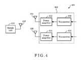
- FIG. 4illustrates a wireless communication system 400 where a base station 402 is implemented with multiple antennas 404 and 406 in support for both the transmit and receive diversity techniques in accordance with one embodiment of the invention.
- the base station 402comprises, for example, transceivers 408 and 410 , and power amplifiers 412 and 414 , coupled to the antennas 404 and 406 , respectively.
- the transceiver 408 and 410receive input signals having a frequency spectrum, and converts the signals into radio frequency signals as outputs to the power amplifiers 412 and 414 .
- the antennas 404 and 406then transmit the amplified signals to the mobile unit 416 via a downlink with its antenna 418 .
- transceiver 408transmits, via antenna 404 , a first half of the frequency spectrum of the input signals, while transceiver 410 transmits, via antenna 406 , a second half of the frequency spectrum of the input signals.
- the placement and the design of the antennas 404 and 406are described in the above embodiments of the present invention.
- One advantage of the present inventionis that the multiple antennas implemented in the base station can be fully utilized for both receive and transmit diversity techniques. This results in a smooth radiation pattern and reduced peak radiation intensity in a free space environment. This also results in an increased probability of signal reception against multi-path and fading.
- Another advantage of the present inventionis its simplicity in design. Because the multiple antenna implemented in the base station can be fully utilized for both receive and transmit diversity techniques, no additional combiner is needed to combine outputs from power amplifiers when the base station transmits signals to the mobile unit.
Landscapes
- Engineering & Computer Science (AREA)
- Computer Networks & Wireless Communication (AREA)
- Signal Processing (AREA)
- Radio Transmission System (AREA)
- Mobile Radio Communication Systems (AREA)
Abstract
Description
Claims (17)
Priority Applications (3)
| Application Number | Priority Date | Filing Date | Title |
|---|---|---|---|
| US11/866,977US8412125B2 (en) | 2006-10-13 | 2007-10-03 | Wireless communication system with transmit diversity designs |
| PCT/US2007/080401WO2008048788A2 (en) | 2006-10-13 | 2007-10-04 | Wireless communication system with transmit diversity designs |
| EP07843815AEP2055035A2 (en) | 2006-10-13 | 2007-10-04 | Wireless communication system with transmit diversity designs |
Applications Claiming Priority (2)
| Application Number | Priority Date | Filing Date | Title |
|---|---|---|---|
| US85162906P | 2006-10-13 | 2006-10-13 | |
| US11/866,977US8412125B2 (en) | 2006-10-13 | 2007-10-03 | Wireless communication system with transmit diversity designs |
Publications (2)
| Publication Number | Publication Date |
|---|---|
| US20080090529A1 US20080090529A1 (en) | 2008-04-17 |
| US8412125B2true US8412125B2 (en) | 2013-04-02 |
Family
ID=39303611
Family Applications (1)
| Application Number | Title | Priority Date | Filing Date |
|---|---|---|---|
| US11/866,977Active2030-03-29US8412125B2 (en) | 2006-10-13 | 2007-10-03 | Wireless communication system with transmit diversity designs |
Country Status (3)
| Country | Link |
|---|---|
| US (1) | US8412125B2 (en) |
| EP (1) | EP2055035A2 (en) |
| WO (1) | WO2008048788A2 (en) |
Cited By (1)
| Publication number | Priority date | Publication date | Assignee | Title |
|---|---|---|---|---|
| US9843291B2 (en) | 2015-08-07 | 2017-12-12 | Qualcomm Incorporated | Cascaded switch between pluralities of LNAS |
Families Citing this family (2)
| Publication number | Priority date | Publication date | Assignee | Title |
|---|---|---|---|---|
| US9112555B2 (en) | 2012-11-16 | 2015-08-18 | Cisco Technology, Inc. | Transmit correlated array gain reduction |
| CN109274378A (en)* | 2017-07-17 | 2019-01-25 | 西安中兴新软件有限责任公司 | A kind of radio circuit, communication terminal and radio frequency transmit-receive method |
Citations (15)
| Publication number | Priority date | Publication date | Assignee | Title |
|---|---|---|---|---|
| US3662268A (en)* | 1970-11-17 | 1972-05-09 | Bell Telephone Labor Inc | Diversity communication system using distinct spectral arrangements for each branch |
| US5652764A (en)* | 1995-01-17 | 1997-07-29 | Kabushiki Kaisha Toshiba | Radio communication system |
| US5983081A (en) | 1996-03-29 | 1999-11-09 | Nokia Mobile Phones, Ltd. | Method for generating frequencies in a direct conversion transceiver of a dual band radio communication system, a direct conversion transceiver of a dual band radio communication system and the use of this method and apparatus in a mobile station |
| US6006075A (en)* | 1996-06-18 | 1999-12-21 | Telefonaktiebolaget L M Ericsson (Publ) | Method and apparatus for transmitting communication signals using transmission space diversity and frequency diversity |
| US6026307A (en) | 1996-12-02 | 2000-02-15 | Telefonaktiebolaget Lm Ericsson | Arrangement in a communication system |
| US6088003A (en)* | 1998-12-28 | 2000-07-11 | Nortel Networks Corporation | Six sector antenna structure |
| US20030020651A1 (en) | 2001-04-27 | 2003-01-30 | Crilly William J. | Wireless packet switched communication systems and networks using adaptively steered antenna arrays |
| US20040160372A1 (en) | 2002-12-19 | 2004-08-19 | Fred Pulver | Systems and methods for wireless telecommunications |
| US20050175073A1 (en)* | 2002-11-01 | 2005-08-11 | Kari Pajukoski | Data transmission method and transmitter |
| US20050276348A1 (en)* | 1999-04-19 | 2005-12-15 | Patrick Vandenameele | Method and apparatus for multi-user transmission |
| US20060087476A1 (en) | 2005-06-09 | 2006-04-27 | Andrew Corporation | Antenna sector frame |
| US7139324B1 (en)* | 2000-06-02 | 2006-11-21 | Nokia Networks Oy | Closed loop feedback system for improved down link performance |
| USRE40434E1 (en)* | 1997-05-14 | 2008-07-15 | Andrew Corporation | High isolation dual polarized antenna system using dipole radiating elements |
| US7430430B2 (en)* | 2003-12-16 | 2008-09-30 | Magnolia Broadband Inc. | Adjusting a signal at a diversity system |
| US7711030B2 (en)* | 2004-07-30 | 2010-05-04 | Rearden, Llc | System and method for spatial-multiplexed tropospheric scatter communications |
- 2007
- 2007-10-03USUS11/866,977patent/US8412125B2/enactiveActive
- 2007-10-04WOPCT/US2007/080401patent/WO2008048788A2/enactiveApplication Filing
- 2007-10-04EPEP07843815Apatent/EP2055035A2/ennot_activeWithdrawn
Patent Citations (15)
| Publication number | Priority date | Publication date | Assignee | Title |
|---|---|---|---|---|
| US3662268A (en)* | 1970-11-17 | 1972-05-09 | Bell Telephone Labor Inc | Diversity communication system using distinct spectral arrangements for each branch |
| US5652764A (en)* | 1995-01-17 | 1997-07-29 | Kabushiki Kaisha Toshiba | Radio communication system |
| US5983081A (en) | 1996-03-29 | 1999-11-09 | Nokia Mobile Phones, Ltd. | Method for generating frequencies in a direct conversion transceiver of a dual band radio communication system, a direct conversion transceiver of a dual band radio communication system and the use of this method and apparatus in a mobile station |
| US6006075A (en)* | 1996-06-18 | 1999-12-21 | Telefonaktiebolaget L M Ericsson (Publ) | Method and apparatus for transmitting communication signals using transmission space diversity and frequency diversity |
| US6026307A (en) | 1996-12-02 | 2000-02-15 | Telefonaktiebolaget Lm Ericsson | Arrangement in a communication system |
| USRE40434E1 (en)* | 1997-05-14 | 2008-07-15 | Andrew Corporation | High isolation dual polarized antenna system using dipole radiating elements |
| US6088003A (en)* | 1998-12-28 | 2000-07-11 | Nortel Networks Corporation | Six sector antenna structure |
| US20050276348A1 (en)* | 1999-04-19 | 2005-12-15 | Patrick Vandenameele | Method and apparatus for multi-user transmission |
| US7139324B1 (en)* | 2000-06-02 | 2006-11-21 | Nokia Networks Oy | Closed loop feedback system for improved down link performance |
| US20030020651A1 (en) | 2001-04-27 | 2003-01-30 | Crilly William J. | Wireless packet switched communication systems and networks using adaptively steered antenna arrays |
| US20050175073A1 (en)* | 2002-11-01 | 2005-08-11 | Kari Pajukoski | Data transmission method and transmitter |
| US20040160372A1 (en) | 2002-12-19 | 2004-08-19 | Fred Pulver | Systems and methods for wireless telecommunications |
| US7430430B2 (en)* | 2003-12-16 | 2008-09-30 | Magnolia Broadband Inc. | Adjusting a signal at a diversity system |
| US7711030B2 (en)* | 2004-07-30 | 2010-05-04 | Rearden, Llc | System and method for spatial-multiplexed tropospheric scatter communications |
| US20060087476A1 (en) | 2005-06-09 | 2006-04-27 | Andrew Corporation | Antenna sector frame |
Non-Patent Citations (1)
| Title |
|---|
| PCT International Search Report and Written Opinion of the International Searching Authority, Mar. 11, 2008. |
Cited By (2)
| Publication number | Priority date | Publication date | Assignee | Title |
|---|---|---|---|---|
| US9843291B2 (en) | 2015-08-07 | 2017-12-12 | Qualcomm Incorporated | Cascaded switch between pluralities of LNAS |
| US10333469B2 (en) | 2015-08-07 | 2019-06-25 | Qualcomm Incorporated | Cascaded switch between pluralities of LNAS |
Also Published As
| Publication number | Publication date |
|---|---|
| US20080090529A1 (en) | 2008-04-17 |
| EP2055035A2 (en) | 2009-05-06 |
| WO2008048788A3 (en) | 2008-06-12 |
| WO2008048788A2 (en) | 2008-04-24 |
Similar Documents
| Publication | Publication Date | Title |
|---|---|---|
| US11990978B2 (en) | Active repeater device for operational mode based beam pattern changes for communication with a plurality of user equipment | |
| KR101336531B1 (en) | Method and apparatus for reducing combiner loss in a multi-sector, omni-base station | |
| US8942158B2 (en) | Relaying system and method with partner relays and selective transmission | |
| US7113748B2 (en) | System and method for improving polarization matching on a cellular communication forward link | |
| US6697641B1 (en) | Method and system for improving communication | |
| US8560018B2 (en) | Flexible sectorization in wireless communication systems | |
| US20100136900A1 (en) | Radio Relay Device and Method | |
| EP0879507B1 (en) | Antenna arrangement | |
| EP1334633B1 (en) | Mode switching in adaptive array communications systems | |
| CA2323881A1 (en) | Adaptive personal repeater | |
| KR20000077161A (en) | Antenna array system having coherent and noncoherent reception characteristics | |
| CN104335504A (en) | Method and apparatus for amplifying multiple input multiple output (MIMO) in wireless communication system | |
| US8412125B2 (en) | Wireless communication system with transmit diversity designs | |
| KR101945193B1 (en) | Antenna apparatus for base station and control method thereof | |
| KR101861270B1 (en) | Method for controlling of beamforming and apparatus thereof | |
| KR100244197B1 (en) | A system for transmitting and receiving data using co-channel in fixed/mobile cellular systems | |
| EP2552173A1 (en) | Mobile communication method und system comprising network and antenna sharing and hierarchical sectorization | |
| JP2008060851A (en) | Wireless communication system, wireless communication method, wireless base station apparatus, and wireless receiving station apparatus | |
| JP2006352328A (en) | Mobile communication relaying system | |
| KR20040107176A (en) | High Quality of Wave is to Repeater with Diversity | |
| KR20120074512A (en) | Rf repeater having a function of interference cancellation |
Legal Events
| Date | Code | Title | Description |
|---|---|---|---|
| AS | Assignment | Owner name:NAVINI NETWORKS, INC, TEXAS Free format text:ASSIGNMENT OF ASSIGNORS INTEREST;ASSIGNOR:SMITH, RICHARD L.;REEL/FRAME:020062/0319 Effective date:20071002 | |
| AS | Assignment | Owner name:NAVINI NETWORKS, INC. UNDER THE NAME OF CISCO-NAVI Free format text:MERGER;ASSIGNOR:NIGHT ACQUISITION CORP.;REEL/FRAME:021410/0184 Effective date:20071219 Owner name:CISCO-NAVINI NETWORKS LLC, CALIFORNIA Free format text:CHANGE OF NAME;ASSIGNOR:CISCO-NAVINI NETWORKS, INC.;REEL/FRAME:021410/0713 Effective date:20071220 Owner name:CISCO TECHNOLOGY, INC., CALIFORNIA Free format text:ASSIGNMENT OF ASSIGNORS INTEREST;ASSIGNOR:CISCO-NAVINI NETWORKS LLC;REEL/FRAME:021412/0001 Effective date:20071228 Owner name:CISCO-NAVINI NETWORKS LLC,CALIFORNIA Free format text:CHANGE OF NAME;ASSIGNOR:CISCO-NAVINI NETWORKS, INC.;REEL/FRAME:021410/0713 Effective date:20071220 Owner name:CISCO TECHNOLOGY, INC.,CALIFORNIA Free format text:ASSIGNMENT OF ASSIGNORS INTEREST;ASSIGNOR:CISCO-NAVINI NETWORKS LLC;REEL/FRAME:021412/0001 Effective date:20071228 | |
| STCF | Information on status: patent grant | Free format text:PATENTED CASE | |
| FPAY | Fee payment | Year of fee payment:4 | |
| MAFP | Maintenance fee payment | Free format text:PAYMENT OF MAINTENANCE FEE, 8TH YEAR, LARGE ENTITY (ORIGINAL EVENT CODE: M1552); ENTITY STATUS OF PATENT OWNER: LARGE ENTITY Year of fee payment:8 | |
| MAFP | Maintenance fee payment | Free format text:PAYMENT OF MAINTENANCE FEE, 12TH YEAR, LARGE ENTITY (ORIGINAL EVENT CODE: M1553); ENTITY STATUS OF PATENT OWNER: LARGE ENTITY Year of fee payment:12 |