US8411085B2 - Constructing view compositions for domain-specific environments - Google Patents
Constructing view compositions for domain-specific environmentsDownload PDFInfo
- Publication number
- US8411085B2 US8411085B2US12/163,867US16386708AUS8411085B2US 8411085 B2US8411085 B2US 8411085B2US 16386708 AUS16386708 AUS 16386708AUS 8411085 B2US8411085 B2US 8411085B2
- Authority
- US
- United States
- Prior art keywords
- data
- view
- model
- component
- domain
- Prior art date
- Legal status (The legal status is an assumption and is not a legal conclusion. Google has not performed a legal analysis and makes no representation as to the accuracy of the status listed.)
- Expired - Fee Related, expires
Links
Images


Classifications
- G—PHYSICS
- G06—COMPUTING OR CALCULATING; COUNTING
- G06T—IMAGE DATA PROCESSING OR GENERATION, IN GENERAL
- G06T11/00—2D [Two Dimensional] image generation
- G06T11/20—Drawing from basic elements, e.g. lines or circles
- G06T11/206—Drawing of charts or graphs
- G—PHYSICS
- G06—COMPUTING OR CALCULATING; COUNTING
- G06T—IMAGE DATA PROCESSING OR GENERATION, IN GENERAL
- G06T13/00—Animation
- G—PHYSICS
- G06—COMPUTING OR CALCULATING; COUNTING
- G06T—IMAGE DATA PROCESSING OR GENERATION, IN GENERAL
- G06T19/00—Manipulating 3D models or images for computer graphics
Definitions
- visual itemsin order to convey or receive information, and in order to collaborate.
- visual itemsmight include, for example, concept sketches, engineering drawings, explosions of bills of materials, three-dimensional models depicting various structures such as buildings or molecular structures, training materials, illustrated installation instructions, planning diagrams, and so on.
- CADComputer Aided Design
- solid modeling applicationsallow authors to attach data and constraints to the geometry.
- the application for constructing a bill of materialsmight allow for attributes such as part number and supplier to be associated with each part, the maximum angle between two components, or the like.
- An application that constructs an electronic version of an arenamight have a tool for specifying a minimum clearance between seats, and so on.
- any given applicationdoes have limits on the type of information that can be visually conveyed, how that information is visually conveyed, or the scope of data and behavior that can be attributed to the various visual representations. If the application is to be modified to go beyond these limits, a new application would typically be authored by a computer programmer which expands the capabilities of the application, or provides an entirely new application. Also, there are limits to how much a user (other than the actual author of the model) can manipulate the model to test various scenarios.
- Embodiments described hereinrelate to the construction of a view that contains multiple visual items.
- the visual itemsmay each be constructed and placed in position using logic defined by a view component corresponding to each visual item, where that logic may depend on one or more values populated into parameter(s) of the view component.
- Some of those parameter valuesmay correspond to known model parameter values.
- Others, however,may have been solved for using a model that defines analytical relationships between the model parameters. In one embodiment, which of the model parameters are known, and which are unknown, may not be predetermined. Accordingly, a solver might be prepared for multiple solve operation paths even using a single model.
- the view composition processmay be entirely data-driven, and may include a mechanism for canonicalizing input data, and binding canonicalized input data to the model parameters.
- the view composition frameworkmay operate the same regardless of the domain. The only difference between one domain and another would be in the identity and types of the input data, the identity and type of model parameters, the data-model parameter binding relationships, the specific analytical relationships between the model parameters, the identity, logic and parameters associated with the view components, and/or the binding of the model to view component parameters.
- FIG. 1illustrates an environment in which the principles of the present invention may be employed including a data-driven composition framework that constructs a view composition that depends on input data;
- FIG. 2illustrates a pipeline environment that represents one example of the environment of FIG. 1 ;
- FIG. 3schematically illustrates an embodiment of the data portion of the pipeline of FIG. 2 ;
- FIG. 4schematically illustrates an embodiment of the analytics portion of the pipeline of FIG. 2 ;
- FIG. 5schematically illustrates an embodiment of the view portion of the pipeline of FIG. 2 ;
- FIG. 6illustrates a rendering of a view composition that may be constructed by the pipeline of FIG. 2 ;
- FIG. 7illustrates a flowchart of a method for generating a view composition using the pipeline environment of FIG. 2 ;
- FIG. 8illustrates a flowchart of a method for regenerating a view composition in response to user interaction with the view composition using the pipeline environment of FIG. 2 ;
- FIG. 9schematically illustrates the solver of the analytics portion of FIG. 4 in further detail including a collection of specialized solvers
- FIG. 10illustrates a flowchart of the solver of FIG. 9 solving for output model variables by coordinating the actions of a collection of specialized solvers;
- FIG. 11illustrates a rendering of an integrated view composition that extends the example of FIG. 6 ;
- FIG. 12illustrates a visualization of a shelf layout and represents just one of countless applications that the principles described herein may apply to;
- FIG. 13illustrates a visualization of an urban plan that the principles described herein may also apply to
- FIG. 14illustrates a conventional visualization comparing children's education, that the principles of the present invention may apply to thereby creating a more dynamic learning environment
- FIG. 15illustrates a conventional visualization comparing population density, that the principles of the present invention may apply to thereby creating a more dynamic learning environment
- FIG. 16illustrates a computing system that represents an environment in which the composition framework of FIG. 1 (or portions thereof) may be implemented.
- FIG. 1illustrates a visual composition environment 100 that may be used to construct an interactive visual composition.
- the construction of the interactive visual compositionis performed using data-driven analytics and visualization of the analytical results.
- the environment 100includes a composition framework 110 that performs logic that is performed independent of the problem-domain of the view composition 130 .
- the same composition framework 110may be used to compose interactive view compositions for city plans, molecular models, grocery shelf layouts, machine performance or assembly analysis, or other domain-specific renderings.
- the composition framework 110uses domain-specific data 120 , however, to construct the actual visual composition 130 that is specific to the domain. Accordingly, the same composition framework 110 may be used to construct view compositions for any number of different domains by changing the domain-specific data 120 , rather than having to recode the composition framework 110 itself. Thus, the composition framework 110 of the pipeline 100 may apply to a potentially unlimited number of problem domains, or at least to a wide variety of problem domains, by altering data, rather than recoding and recompiling.
- the view composition 130may then be supplied as instructions to an appropriate 2-D or 3-D rendering module.
- the architecture described hereinalso allows for convenient incorporation of pre-existing view composition models as building blocks to new view composition models. In one embodiment, multiple view compositions may be included in an integrated view composition to allow for easy comparison between two possible solutions to a model.
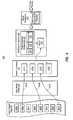
- FIG. 2illustrates an example architecture of the composition framework 110 in the form of a pipeline environment 200 .
- the pipeline environment 200includes, amongst other things, the pipeline 201 itself.
- the pipeline 201includes a data portion 210 , an analytics portion 220 , and a view portion 230 , which will each be described in detail with respect to subsequent FIGS. 3 through 5 , respectively, and the accompanying description.
- the data portion 210 of the pipeline 201may accept a variety of different types of data and presents that data in a canonical form to the analytics portion 220 of the pipeline 201 .
- the analytics portion 220binds the data to various model parameters, and solves for the unknowns in the model parameters using model analytics.
- the various parameter valuesare then provided to the view portion 230 , which constructs the composite view using those values of the model parameters.
- the pipeline environment 200also includes an authoring component 240 that allows an author or other user of the pipeline 201 to formulate and/or select data to provide to the pipeline 201 .
- the authoring component 240may be used to supply data to each of data portion 210 (represented by input data 211 ), analytics portion 220 (represented by analytics data 221 ), and view portion 230 (represented by view data 231 ).
- the various data 211 , 221 and 231represent an example of the domain-specific data 120 of FIG. 1 , and will be described in much further detail hereinafter.
- the authoring component 240supports the providing of a wide variety of data including for example, data schemas, actual data to be used by the model, the location or range of possible locations of data that is to be brought in from external sources, visual (graphical or animation) objects, user interface interactions that can be performed on a visual, modeling statements (e.g., views, equations, constraints), bindings, and so forth.
- the authoring componentis but one portion of the functionality provided by an overall manager component (not shown in FIG. 2 , but represented by the composition framework 110 of FIG. 1 ).
- the manageris an overall director that controls and sequences the operation of all the other components (such as data connectors, solvers, viewers, and so forth) in response to events (such as user interaction events, external data events, and events from any of the other components such as the solvers, the operating system, and so forth).
- componentssuch as data connectors, solvers, viewers, and so forth
- eventssuch as user interaction events, external data events, and events from any of the other components such as the solvers, the operating system, and so forth.
- an interactive view composition applicationinvolves two key times: authoring time, and use time.
- the functionality of the interactive view composition applicationis coded by a programmer to provide an interactive view composition that is specific to the desired domain.
- the author of an interior design applicatione.g., typically, a computer programmer
- a usere.g., perhaps a home owner or a professional interior designer
- the applicationmight then use the application to perform any one or more of the set of finite actions that are hard coded into the application.
- the usermight specify the dimensions of a virtual room being displayed, add furniture and other interior design components to the room, perhaps rotate the view to get various angles on the room, set the color of each item, and so forth.
- the useris limited to the finite set of actions that were enabled by the application author. For example, unless offered by the application, the user would not be able to use the application to automatically figure out which window placement would minimize ambient noise, how the room layout performs according to Feng Shui rules, or minimize solar heat contribution.
- the authoring component 240is used to provide data to an existing pipeline 201 , where it is the data that drives the entire process from defining the input data, to defining the analytical model, to defining how the results of the analytics are visualized in the view composition. Accordingly, one need not perform any coding in order to adapt the pipeline 201 to any one of a wide variety of domains and problems. Only the data provided to the pipeline 201 is what is to change in order to apply the pipeline 201 to visualize a different view composition either from a different problem domain altogether, or to perhaps adjust the problem solving for an existing domain.
- the modelcan be modified and/or extended at runtime.
- the modelcan be modified and/or extended at runtime.
- the pipeline environment 200also includes a user interaction response module 250 that detects when a user has interacted with the displayed view composition, and then determines what to do in response. For example, some types of interactions might require no change in the data provided to the pipeline 201 and thus require no change to the view composition. Other types of interactions may change one or more of the data 211 , 221 , or 231 . In that case, this new or modified data may cause new input data to be provided to the data portion 210 , might require a reanalysis of the input data by the analytics portion 220 , and/or might require a re-visualization of the view composition by the view portion 230 .
- the pipeline 201may be used to extend data-driven analytical visualizations to perhaps an unlimited number of problem domains, or at least to a wide variety of problem domains. Furthermore, one need not be a programmer to alter the view composition to address a wide variety of problems.
- Each of the data portion 210 , the analytics portion 220 and the view portion 230 of the pipeline 201will now be described with respect to respective data portion 300 of FIG. 3 , the analytics portion 400 of FIG. 4 , and the view portion 500 of FIG. 5 , in that order. As will be apparent from FIGS.
- the pipeline 201may be constructed as a series of transformation component where they each 1) receive some appropriate input data, 2) perform some action in response to that input data (such as performing a transformation on the input data), and 3) output data which then serves as input data to the next transformation component.
- the pipeline 201may be implemented on the client, on the server, or may even be distributed amongst the client and the server without restriction.
- the pipeline 201might be implemented on the server and provide rendering instructions as output.
- a browser at the client-sidemay then just render according to the rendering instructions received from the server.
- the pipeline 201may be contained on the client with authoring and/or use performed at the client. Even if the pipeline 201 was entirely at the client, the pipeline 201 might still search data sources external to the client for appropriate information (e.g., models, connectors, canonicalizers, schemas, and others).
- the modelis hosted on a server but web browser modules are dynamically loaded on the client so that some of the model's interaction and viewing logic is made to run on the client (thus allowing richer and faster interactions and views).
- FIG. 3illustrates just one of many possible embodiments of a data portion 300 of the pipeline 201 of FIG. 2 .
- One of the functions of the data portion 300is to provide data in a canonical format that is consistent with schemas understood by the analytics portion 400 of the pipeline discussed with respect to FIG. 4 .
- the data portionincludes a data access component 310 that accesses the heterogenic data 301 .
- the input data 301may be “heterogenic” in the sense that the data may (but need not) be presented to the data access component 310 in a canonical form.
- the data portion 300is structured such that the heterogenic data could be of a wide variety of formats.
- Examples of different kinds of domain data that can be accessed and operated on by modelsinclude text and XML documents, tables, lists, hierarchies (trees), SQL database query results, BI (business intelligence) cube query results, graphical information such as 2D drawings and 3D visual models in various formats, and combinations thereof (i.e, a composite).
- the kind of data that can be accessedcan be extended declaratively, by providing a definition (e.g., a schema) for the data to be accessed. Accordingly, the data portion 300 permits a wide variety of heterogenic input into the model, and also supports runtime, declarative extension of accessible data types.
- the data access portion 300includes a number of connectors for obtaining data from a number of different data sources. Since one of the primary functions of the connector is to place corresponding data into canonical form, such connectors will often be referred to hereinafter and in the drawings as “canonicalizers”. Each canonicalizer might have an understanding of the specific Application Program Interfaces (API's) of its corresponding data source. The canonicalizer might also include the corresponding logic for interfacing with that corresponding API to read and/or write data from and to the data source. Thus, canonicalizers bridge between external data sources and the memory image of the data.
- API'sApplication Program Interfaces
- the data access component 310evaluates the input data 301 . If the input data is already canonical and thus processable by the analytics portion 400 , then the input data may be directly provided as canonical data 340 to be input to the analytics portion 400 .
- the data canonicalization components 330are actually a collection of data canonicalization components 330 , each capable of converting input data having particular characteristics into canonical form.
- the collection of canonicalization components 330is illustrated as including four canonicalization components 331 , 332 , 333 and 334 .
- the ellipses 335represents that there may be other numbers of canonicalization components as well, perhaps even fewer that the four illustrated.
- the input data 301may even include a canonicalizer itself as well as an identification of correlated data characteristic(s).
- the data portion 300may then register the correlated data characteristics, and provide the canonicalization component to the data canonicalization component collection 330 , where it may be added to the available canonicalization components. If input data is later received that has those correlated characteristics, the data portion 310 may then assign the input data to the correlated canonicalization component.
- Canonicalization componentscan also be found dynamically from external sources, such as from defined component libraries on the web. For example, if the schema for a given data source is known but the needed canonicalizer is not present, the canonicalizer can be located from an external component library, provided such a library can be found and contains the needed components.
- the pipelinemight also parse data for which no schema is yet known and compare parse results versus schema information in known component libraries to attempt a dynamic determination of the type of the data, and thus to locate the needed canonicalizer components.
- the input datamay instead provide a transformation definition defining canonicalization transformations.
- the collection 330may then be configured to convert that transformations definition into a corresponding canonicalization component that enforces the transformations along with zero or more standard default canonicalization transformation. This represents an example of a case in which the data portion 300 consumes the input data and does not provide corresponding canonicalized data further down the pipeline. In perhaps most cases, however, the input data 301 results in corresponding canonicalized data 340 being generated.
- the data portion 310may be configured to assign input data to the data canonicalization component on the basis of a file type and/or format type of the input data. Other characteristics might include, for example, a source of the input data.
- a default canonicalization componentmay be assigned to input data that does not have a designated corresponding canonicalization component. The default canonicalization component may apply a set of rules to attempt to canonicalize the input data. If the default canonicalization component is not able to canonicalize the data, the default canonicalization component might trigger the authoring component 240 of FIG. 2 to prompt the user to provide a schema definition for the input data.
- the authoring component 240might present a schema definition assistant to help the author generate a corresponding schema definition that may be used to transform the input data into canonical form.
- the schema that accompanies the dataprovides sufficient description of the data that the rest of the pipeline 201 does not need new code to interpret the data. Instead, the pipeline 201 includes code that is able to interpret data in light of any schema that is expressible an accessible schema declaration language.
- canonical data 340is provided as output data from the data portion 300 and as input data to the analytics portion 400 .
- the canonical datamight include fields that include a variety of data types.
- the fieldsmight includes simple data types such as integers, floating point numbers, strings, vectors, arrays, collections, hierarchical structures, text, XML documents, tables, lists, SQL database query results, BI (business intelligence) cube query results, graphical information such as 2D drawings and 3D visual models in various formats, or even complex combinations of these various data types.
- the canonicalization processis able to canonicalize a wide variety of input data.
- the variety of input data that the data portion 300 is able to acceptis expandable. This is helpful in the case where multiple models are combined as will be discussed later in this description.
- FIG. 4illustrates analytics portion 400 which represents an example of the analytics portion 220 of the pipeline 201 of FIG. 2 .
- the data portion 300provided the canonicalized data 401 to the data-model binding component 410 . While the canonicalized data 401 might have any canonicalized form, and any number of parameters, where the form and number of parameters might even differ from one piece of input data to another. For purposes of discussion, however, the canonical data 401 has fields 402 A through 402 H, which may collectively be referred to herein as “fields 402 ”.
- the analytics portion 400includes a number of model parameters 411 .
- the type and number of model parametersmay differ according to the model. However, for purposes of discussion of a particular example, the model parameters 411 will be discussed as including model parameters 411 A, 411 B, 411 C and 411 D.
- the identity of the model parameters, and the analytical relationships between the model parametersmay be declaratively defined without using imperative coding.
- a data-model binding component 410intercedes between the canonicalized data fields 402 and the model parameters 411 to thereby provide bindings between the fields.
- the data field 402 Bis bound to model parameter 411 A as represented by arrow 403 A.
- the value from data field 402 Bis used to populate the model parameter 411 A.
- the data field 402 Eis bound to model parameter 411 B (as represented by arrow 403 B)
- data field 402 His bound to model parameter 411 C (as represented by arrow 403 C).
- the data fields 402 A, 402 C, 402 D, 402 F and 402 Gare not shown bound to any of the model parameters. This is to emphasize that not all of the data fields from input data are always required to be used as model parameters. In one embodiment, one or more of these data fields may be used to provide instructions to the data-model binding component 410 on which fields from the canonicalized data (for this canonicalized data or perhaps any future similar canonicalized data) are to be bound to which model parameter. This represents an example of the kind of analytics data 221 that may be provided to the analytics portion 220 of FIG. 2 .
- the definition of which data fields from the canonicalized data are bound to which model parametersmay be formulated in a number of ways.
- the bindingsmay be 1) explicitly set by the author at authoring time, 2) explicit set by the user at use time (subject to any restrictions imposed by the author), 3) automatic binding by the authoring component 240 based on algorithmic heuristics, and/or 4) prompting by the authoring component of the author and/or user to specify a binding when it is determined that a binding cannot be made algorithmically.
- bindingsmay also be resolved as part of the model logic itself.
- model parametersFor instance, if one of the model parameters represents pressure, the author can name that model parameter “Pressure” or “P” or any other symbol that makes sense to the author.
- the authorcan even rename the model parameter which, in one embodiment, might cause the data model binding component 410 to automatically update to allow bindings that were previously to the model parameter of the old name to instead be bound to the model parameter of the new name, thereby preserving the desired bindings.
- This mechanism for bindingalso allows binding to be changed declaratively at runtime.
- the model parameter 411 Dis illustrated with an asterisk to emphasize that in this example, the model parameter 411 D was not assigned a value by the data-model binding component 410 . Accordingly, the model parameter 411 D remains an unknown. In other words, the model parameter 411 D is not assigned a value.
- the modeling component 420performs a number of functions. First, the modeling component 420 defines analytical relationships 421 between the model parameters 411 .
- the analytical relationships 421are categorized into three general categories including equations 431 , rules 432 and constraints 433 . However, the list of solvers is extensible. In one embodiment, for example, one or more simulations may be incorporated as part of the analytical relationships provided a corresponding simulation engine is provided and registered as a solver.
- rulesmeans a conditional statement where if one or more conditions are satisfied (the conditional or “if” portion of the conditional statement), then one or more actions are to be taken (the consequence or “then” portion of the conditional statement).
- a ruleis applied to the model parameters if one or more model parameters are expressed in the conditional statement, or one or more model parameters are expressed in the consequence statement.
- a restrictionmeans that a restriction is applied to one or more model parameters. For instance, in a city planning model, a particular house element may be restricted to placement on a map location that has a subset of the total possible zoning designations. A bridge element may be restricted to below a certain maximum length, or a certain number of lanes.
- the modeling component 420may provide a mechanism for the author to provide a natural symbolic expression for equations, rules and constraints.
- an author of a thermodynamics related modelmay simply copy and paste equations from a thermodynamics textbook.
- the ability to bind model parameters to data fieldsallows the author to use whatever symbols the author is familiar with (such as the exact symbols used in the author's relied-upon textbooks) or the exact symbols that the author would like to use.
- the modeling component 420Prior to solving, the modeling component 420 also identifies which of the model parameters are to be solved for (i.e., hereinafter, the “output model variable” if singular, or “output model variables” if plural, or “output model variable(s)” if there could be a single or plural output model variables).
- the output model variablesmay be unknown parameters, or they might be known model parameters, where the value of the known model parameter is subject to change in the solve operation.
- model parameters 411 A, 411 B and 411 Care known, and model parameter 411 D is unknown. Accordingly, unknown model parameter 411 D might be one of the output model variables.
- one or more of the known model parameters 411 A, 411 B and 411 Cmight also be output model variables.
- the solver 440then solves for the output model variable(s), if possible.
- the solver 440is able to solve for a variety of output model variables, even within a single model so long as sufficient input model variables are provided to allow the solve operation to be performed.
- Input model variablesmight be, for example, known model parameters whose values are not subject to change during the solve operation. For instance, in FIG. 4 , if the model parameters 411 A and 411 D were input model variables, the solver might instead solve for output model variables 411 B and 411 C instead.
- the solvermight output any one of a number of different data types for a single model parameter. For instance, some equation operations (such as addition, subtraction, and the like) apply regardless of the whether the operands are integers, floating point, vectors of the same, or matrices of the same.
- the solver 400might still present a partial solution for that output model variable, even if a full solve to the actual numerical result (or whatever the solved-for data type) is not possible.
- Thisallows the pipeline to facilitate incremental development by prompting the author as to what information is needed to arrive at a full solve. This also helps to eliminate the distinction between author time and use time, since at least a partial solve is available throughout the various authoring stages.
- the solver 440is only able to solve for one of the output model variables “d”, and assign a value of 6 (an integer) to the model parameter called “d”, but the solver 440 is not able to solve for “c”. Since “a” depends from “c”, the model parameter called “a” also remains an unknown and unsolved for. In this case, instead of assigning an integer value to “a”, the solver might do a partial solve and output the string value of “c+11” to the model parameter “a”.
- the solver 440is shown in simplified form in FIG. 4 . However, the solver 440 may direct the operation of multiple constituent solvers as will be described with respect to FIG. 9 .
- the modeling component 420then makes the model parameters (including the now known and solved—for output model variables) available as output to be provided to the view portion 500 of FIG. 5 .
- FIG. 5illustrates a view portion 500 which represents an example of the view portion 230 of FIG. 2 .
- the view portion 500receives the model parameters 411 from the analytics portion 400 of FIG. 4 .
- the view portionalso includes a view components repository 520 that contains a collection of view components.
- the view components repository 520 in this exampleis illustrated as including view components 521 through 524 , although the view components repository 520 may contain any number of view components.
- the view componentseach may include zero or more input parameters.
- view component 521does not include any input parameters.
- view component 522includes two input parameters 542 A and 542 B.
- View component 523includes one input parameter 543
- view component 524includes one input parameter 544 . That said, this is just an example.
- the input parametersmay, but need not necessary, affect how the visual item is rendered.
- the fact that the view component 521 does not include any input parametersemphasizes that there can be views that are generated without reference to any model parameters.
- Each view component 521 through 524includes or is associated with corresponding logic that, when executed by the view composition component 540 using the corresponding view component input parameter(s), if any, causes a corresponding view item to be placed in virtual space 550 .
- That virtual itemmay be a static image or object, or may be a dynamic animated virtual item or object
- each of view components 521 through 524are associated with corresponding logic 531 through 534 that, when executed causes the corresponding virtual item 551 through 554 , respectively, to be rendered in virtual space 550 .
- the virtual itemsare illustrated as simple shapes. However, the virtual items may be quite complex in form perhaps even including animation. In this description, when a view item is rendered in virtual space, that means that the view composition component has authored sufficient instructions that, when provided to the rendering engine, the rendering engine is capable if displaying the view item on the display in the designated location and in the designated manner.
- the view components 521 through 524may be provided perhaps even as view data to the view portion 500 using, for example, the authoring component 240 of FIG. 2 .
- the authoring component 240might provide a selector that enables the author to select from several geometric forms, or perhaps to compose other geometric forms.
- the authormight also specify the types of input parameters for each view component, whereas some of the input parameters may be default input parameters imposed by the view portion 500 .
- the logic that is associated with each view component 521 through 524may be provided also a view data, and/or may also include some default functionality provided by the view portion 500 itself.
- the view portion 500includes a model-view binding component 510 that is configured to bind at least some of the model parameters to corresponding input parameters of the view components 521 through 524 .
- model parameter 411 Ais bound to the input parameter 542 A of view component 522 as represented by arrow 511 A.
- Model parameter 411 Bis bound to the input parameter 542 B of view component 522 as represented by arrow 511 B.
- model parameter 411 Dis bound to the input parameters 543 and 544 of view components 523 and 524 , respectively, as represented by arrow 511 C.
- the model parameter 411 Cis not shown bound to any corresponding view component parameter, emphasizing that not all model parameters need be used by the view portion of the pipeline, even if those model parameters were essential in the analytics portion.
- model parameter 411 Dis shown bound to two different input parameters of view components representing that the model parameters may be bound to multiple view component parameters.
- the definition of the bindings between the model parameters and the view component parametersmay be formulated by 1) being explicitly set by the author at authoring time, 2) explicit set by the user at use time (subject to any restrictions imposed by the author), 3) automatic binding by the authoring component 240 based on algorithmic heuristics, and/or 4) prompting by the authoring component of the author and/or user to specify a binding when it is determined that a binding cannot be made algorithmically.
- the view itemmay include an animation.
- an animationFor example, consider for example a bar chart that plots a company's historical and projected revenues, advertising expenses, and profits by sales region at a given point in time (such as a given calendar quarter). A bar chart could be drawn for each calendar quarter in a desired time span. Now, imagine that you draw one of these charts, say the one for the earliest time in the time span, and then every half second replace it with the chart for the next time span (e.g., the next quarter). The result will be to see the bars representing profit, sales, and advertising expense for each region change in height as the animation proceeds.
- the chart for each time periodis a “cell” in the animation, where the cell shows an instant between movements, where the collection of cells shown in sequence simulates movement.
- Conventional animation modelsallow for animation over time using built-in hard-coded chart types.
- any kind of visualcan be animated, and the animation can be driven by varying any one or any combination of the parameters of the visual component.
- the animationcan be driven by varying any one or any combination of the parameters of the visual component.
- the pipeline 201is also distinguished in its ability to animate due to the following characteristics:
- the sequences of steps for the animation variablecan be computed by the analytics of the model, versus being just a fixed sequence of steps over a predefined range.
- the advertising expenseAs the animation variable, imagine that what is specified is to “animate by advertising expense where advertising expense is increased by 5% for each step” or “where advertising expense is 10% of total expenses for that step”.
- a much more sophisticated exampleis “animate by advertising expense where advertising expense is optimized to maximize the rate of change of sales over time”.
- the solverwill determine a set of steps for advertising spend over time (i.e., for each successive time period such as quarter) such that the rate of growth of sales maximized.
- the userpresumably wants to see not only how fast sales can be made to grow by varying advertising expense, but also wants to learn the quarterly amounts for the advertising expense that achieve this growth (the sequence of values could be plotted as part of the composite visual).
- any kind of visualcan be animated, not just traditional data charts.
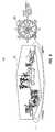
- CADComputer-Aided Design
- Jet engineshave limits on how fast turbines can be rotated before either the turbine blades lose integrity or the bearing overheats.
- this animationwe desire that as air speed is varied the color of the turbine blades and bearing should be varied from blue (safe) to red (critical).
- the values for “safe” and “critical” turbine RPM and bearing temperaturemay well be calculated by the model based on physical characteristics of those parts.
- the pipeline 201can be stopped mid stream so that data and parameters may be modified by the user, and the animation then restarted or resumed.
- the animationmay be stopped at the point the runaway beings, modify some engine design criterion, such as the kind of bearing or bearing surface material, and then continue the animation to see the effect of the change.
- animationscan be defined by the author, and/or left open for the user to manipulate to test various scenarios.
- the modelmay be authored to permit some visuals to be animated by the user according to parameters the user himself selects, and/or over data ranges for the animation variable that the user selects (including the ability to specify computed ranges should that be desired).
- Such animationscan also be displayed side by side as in the other what-if comparison displays. For example, a user could compare an animation of sales and profits over time, animated by time, in two scenarios with differing prevailing interest rates in the future, or different advertising expenses ramps. In the jet engine example, the user could compare the animations of the engine for both the before and after cases of changing the bearing design.
- FIG. 6which illustrated 3-D renderings 600 of a view composition that includes a room layout 601 with furniture laid out within the room, and also includes a Feng Shui meter 602 .
- This exampleis provided merely to show how the principles described herein can apply to any arbitrary view composition, regardless of the domain. Accordingly, the example of FIG. 6 , and any other example view composition described herein, should be viewed strictly as only an example that allows the abstract concept to be more fully understood by reference to non-limiting concrete examples, and not defining the broader scope of the invention.
- the principles described hereinmay apply to construct an enumerable variety of view compositions. Nevertheless, reference to a concrete example can clarify the broader abstract principles.
- FIG. 7illustrates a flowchart of a method 700 for generating a view construction.
- the method 700may be performed by the pipeline environment 200 of FIG. 2 , and thus will be described with frequent reference to the pipeline environment 200 of FIG. 2 , as well as with reference to FIGS. 3 through 5 , which each show specific portions of the pipeline of FIG. 2 . While the method 700 may be performed to construct any view composition, the method 700 will be described with respect to the view composition 600 of FIG. 6 . Some of the acts of the method 700 may be performed by the data portion 210 of FIG. 2 and are listed in the left column of FIG. 7 under the header “Data”. Other of the acts of the method 700 may be performed by the analytics portion 220 of FIG.
- the data portionaccesses input data that at least collectively affects what visual items are displayed or how a given one or more of the visual items are displayed (act 711 ).
- the input datamight include view components for each of the items of furniture. For instance, each of the couch, the chair, the plants, the table, the flowers, and even the room itself may be represented by a corresponding view component.
- the view componentmight have input parameters that are suitable for the view component. If animation were employed, for example, some of the input parameters might affect the flow of the animation. Some of the parameters might affect the display of the visual item, and some parameters might not.
- the roomitself might be a view component.
- Some of the input parametersmight include the dimensions of the room, the orientation of the room, the wall color, the wall texture, the floor color, the floor type, the floor texture, the position and power of the light sources in the room, and so forth.
- the room parametermight have a location of the room expressed in degrees, minutes, and seconds longitude and latitude.
- the room parametermight also include an identification of the author of the room component, and the average rental costs of the room.
- each plantmay be configured with an input parameter specifying a pot style, a pot color, pot dimensions, plant color, plant resiliency, plant dependencies on sunlight, plant daily water intake, plant daily oxygen production, plant position and the like.
- a pot stylea pot color
- pot dimensionsa pot dimension
- plant colora pot dimension
- plant colora pot resiliency
- plant dependencies on sunlighta plant daily water intake
- plant daily oxygen productiona plant position and the like.
- the Feng Shui meter 602may also be a view component.
- the metermight include input parameters such as a diameter, a number of wedges to be contained in the diameter of the meter, a text color and the like.
- the various wedges of the Feng Shui metermay also be view components.
- the input parameters to the view componentsmight be a title (e.g., water, mountain, thunder, wind, fire, earth, lake, heaven), perhaps a graphic to appear in the wedge, a color hue, or the like.
- the analytics portionbinds the input data to the model parameters (act 721 ), determines the output model variables (act 722 ), and uses the model-specific analytical relationships between the model parameters to solve for the output model variables (act 723 ).
- act 721has been previously discussed, and essentially allows flexibility in allowing the author to define the model analytics equations, rules and constraints using symbols that the model author is comfortable with.
- the identification or the output model variablesmay differ from one solving operation to the next. Even though the model parameters may stay the same, the identification of which model parameters are output model variables will depend on the availability of data to bind to particular model parameters. This has remarkable implications in terms of allowing a user to perform what-if scenarios in a given view composition.
- the Fung Shui room example of FIG. 6suppose the user has bought a new chair to place in their living room. The user might provide the design of the room as data into the pipeline. This might be facilitated by the authoring component prompting the user to enter the room dimensions, and perhaps provide a selection tool that allows the user to select virtual furniture to drag and drop into the virtual room at appropriate locations that the actual furniture is placed in the actual room. The user might then select a piece of furniture that may be edited to have the characteristics of the new chair purchased by the user. The user might then drag and drop that chair into the room.
- the Feng Shui meter 602would update automatically. In this case, the position and other attributes of the chair would be input model variables, and the Feng Shui scores would be output model variables.
- the Feng Shui scores of the Feng Shui meterwould update, and the user could thus test the Feng Shui consequences of placing the virtual chair in various locations.
- the usercan get local visual clues (such as, for example, gradient lines or arrows) that tell the user whether moving the chair in a particular direction from its current location makes things better or worse, and how much better or worse.
- the usercould also do something else that is unheard of in conventional view composition.
- the usercould actually change the output model variables. For instance, the user might indicate the desired Feng Shui score in the Feng Shui meter, and leave the position of the virtual chair as the output model variable.
- the solverwould then solve for the output model variable and provide a suggested position or positions of the chair that would achieve at least the designated Feng Shui score.
- the usermay choose to make multiple parameters output model variables, and the system may provide multiple solutions to the output model variables. This is facilitated by a complex solver that is described in further detail with respect to FIG. 9 .
- the model parametersare bound to the input parameters of the parameterized view components (act 731 ). For instance, in the Feng Shui example, after the unknown Feng Shui scores are solved for, the scores are bound as input parameters to Feng Shui meter view component, or perhaps to the appropriate wedge contained in the meter. Alternatively, if the Feng Shui scores were input model variables, the position of the virtual chair may be solved for and provided as an input parameter to the chair view component.
- FSroomis an output model variable and its value, displayed on the meter, changes as user repositions the chair.
- the view componentcan move the chair around, changing d, its distance from the wall, as the user changes the desired value, FSroom, on the meter.
- the view portionthen constructs a view of the visual items (act 732 ) by executing the construction logic associated with the view component using the input parameter(s), if any, to perhaps drive the construction of the view item in the view composition.
- the view constructionmay then be provided to a rendering module, which then uses the view construction as rendering instructions (act 741 ).
- the processing of constructing a viewis treated as a data transformation that is performed by the solver. That is, for a given kind of view (e.g., consider a bar chart), there is a model consisting of rules, equations, and constraints that generates the view by transforming the input data into a displayable output data structure (called a scene graph) which encodes all the low level geometry and associated attributes needed by the rendering software to drive the graphics hardware.
- a scene grapha displayable output data structure
- the input datawould be for example the data series that is to be plotted, along with attributes for things like the chart title, axis labels, and so on.
- the model that generates the barwould have rules, equations, and constraints that would do things like 1) count how many entries the data series consists of in order to determine how many bars to draw, 2) calculate the range (min, max) that the data series spans in order to calculate things like the scale and starting/ending values for each axis, 3) calculate the height of the bar for each data point in the data series based on the previously calculated scale factor, 4) count how many characters are in the chart title in order to calculate a starting position and size for the title so that the title will be properly located and centered with respect to the chart, and so forth.
- the scene graphis an output variable that the model solves for based on the input data.
- an authorcan design entirely new kinds of views, customized existing views, and compose preexisting views into composites, using the same framework that the author uses to author, customize, and compose any kind of model.
- authors who are not programmerscan create new views without drafting new code.
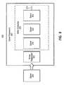
- FIG. 8illustrates a flowchart of a method 800 for responding to user interaction with the view composition.
- the user interaction response moduledetermines which the components of the pipeline should perform further work in order to regenerate the view, and also provides data represented the user interaction, or that is at least dependent on the user interaction, to the pipeline components. In one embodiment, this is done via a transformation pipeline that runs in the reverse (upstream) view/analytics/data direction and is parallel to the (downstream) data/analytics/view pipeline.
- Each transformer in the data/analytics/view pipelineprovides an upstream transformer that handles incoming interaction data. These transformers can either be null (passthroughs, which get optimized out of the path) or they can perform a transformation operation on the interaction data to be fed further upstream.
- Thisprovides positive performance and responsiveness of the pipeline in that 1) interaction behaviors that would have no effect on upstream transformations, such as a view manipulation that has no effect on source data, can be handled at the most appropriate (least upstream) point in the pipeline and 2) intermediate transformers can optimize view update performance by sending heuristically-determined updates back downstream, ahead of the final updates that will eventually come from further upstream transformers. For example, upon receipt of a data edit interaction, a view-level transformer could make an immediate view update directly into the scene graph for the view (for edits it knows how to interpret), with the final complete update coming later from the upstream data transformer where the source data is actually edited.
- intermediate transformerscan provide the needed upstream mapping. For example, dragging a point on a graph of a computed result could require a backwards solve that would calculate new values for multiple source data items that feed the computed value on the graph.
- the solver-level upstream transformerwould be able to invoke the needed solve and to propagate upstream the needed data edits.
- FIG. 8illustrates a flowchart of a method 800 for responding to user interaction with the view construction.
- itis first determined whether or not the user interaction requires regeneration of the view (decision block 802 ). This may be performed by the rendering engine raising an event that is interpreted by the user interaction response component 250 of FIG. 2 . If the user interaction does not require regeneration of the view (No in decision block 802 ), then the pipeline does not perform any further action to reconstruct the view (act 803 ), although the rendering engine itself may perform some transformation on the view.
- An example of such a user interactionmight be if the user were to increase the contrast of the rendering of the view construction, or rotate the view construction. Since those actions might be undertaken by the rendering engine itself, the pipeline need perform no work to reconstruct the view in response to the user interaction.
- the viewis reconstructed by the pipeline (act 804 ). This may involve some altering of the data provided to the pipeline. For instance, in the Feng Shui example, suppose the user were to move the position of the virtual chair within the virtual room, the position parameter of the virtual chair component would thus change. An event would be fired informing the analytics portion that the corresponding model parameter representing the position of the virtual chair should be altered as well. The analytics component would then resolve for the Feng Shui scores, repopulate the corresponding input parameters of the Feng Shui meter or wedges, causing the Feng Shui meter to update with current Feng Shui scores suitable for the new position of the chair.
- the user interactionmight require that model parameters that were previously known are now unknown, and that previously unknown parameters are now known. That is one of several possible examples that might require a change in designation of input and output model variables such that previously designated input model variables might become output model variables, and vice versa. In that case, the analytics portion would solve for the new output model variable(s) thereby driving the reconstruction of the view composition.
- FIG. 9illustrates a solver environment 900 that may represent an example of the solver 440 of FIG. 4 .
- the solver environment 900may be implemented in software, hardware, or a combination.
- the solver environment 900includes a solver framework 901 that manages and coordinates the operations of a collection 910 of specialized solvers.
- the collection 910is illustrated as including three specialized solvers 911 , 912 and 913 , but the ellipses 914 represents that there could be other numbers (i.e., more than three or less than three) of specialized solvers as well.
- the ellipsis 914also represents that the collection 910 of specialized solves is extensible.
- FIG. 9illustrates that a new solver 915 is being registered into the collection 910 using the solver registration module 921 .
- a new solvermight be perhaps a simulation solver which accepts one or more known values, and solves for one or more unknown values.
- Other examplesinclude solvers for systems of linear equations, differential equations, polynomials, integrals, root-finders, factorizers, optimizers, and so forth. Every solver can work in numerical mode or in symbolic mode or in mixed numeric-symbolic mode.
- the numeric portions of solutionscan drive the parameterized rendering downstream.
- the symbolic portions of the solutioncan drive partial solution rendering.
- the collection of specialized solversmay include any solver that is suitable for solving for the output model variables. If, for example, the model is to determine drag of a bicycle, the solving of complex calculus equations might be warranted. In that case, a specialized complex calculus solver may be incorporated into the collection 910 to perhaps supplement of replace an existing equations solver.
- each solveris designed to solve for one or more output model variables in a particular kind of analytics relationship. For example, there might be one or more equation solvers configured to solve for unknowns in an equation. There might be one or more rules solvers configured to apply rules to solve for unknowns. There might be one or more constraints solvers configured to apply constraints to thereby solve for unknowns. Other types of solves might be, for example, a simulation solver which performs simulations using input data to thereby construct corresponding output data.
- the solver framework 901is configured to coordinate processing of one or more or all of the specialized solvers in the collection 910 to thereby cause one or more output model variables to be solved for.
- the solver framework 901is then configured to provide the solved for values to one or more other external components.
- the solver framework 901may provide the model parameter values to the view portion 230 of the pipeline, so that the solving operation thereby affects how the view components execute to render a view item, or thereby affect other data that is associated with the view item.
- the model analyticsthemselves might be altered.
- the modelmight be authored with modifiable rules set so that, during a given solve, some rule(s) and/or constraint(s) that are initially inactive become activated, and some that are initially activated become inactivated. Equations can be modified this way as well.
- FIG. 10illustrates a flowchart of a method 1000 for the solver framework 901 to coordinate processing amongst the specialized solvers in the collection 910 .
- the method 1000 of FIG. 10will now be described with frequent reference to the solver environment 900 of FIG. 9 .
- the solver frameworkbegins a solve operation by identifying which of the model parameters are input model variables (act 1001 ), and which of the model parameters are output model variables (act 1002 ), and by identifying the model analytics that define the relationship between the model parameters (act 1003 ). Given this information, the solver framework analyzes dependencies in the model parameters (act 1004 ). Even given a fixed set of model parameters, and given a fixed set of model analytics, the dependencies may change depending on which of the model parameters are input model variables and which are output model variables. Accordingly, the system can infer a dependency graph each time a solve operation is performed using the identity of which model parameters are input, and based on the model analytics. The user need not specify the dependency graph for each solve.
- the solver frameworkBy evaluating dependencies for every solve operation, the solver framework has the flexibility to solve for one set of one or more model variables during one solve operation, and solve for another set of one or more model variables for the next solve operation.
- the modelmay not have any output model variables at all.
- the solvewill verify that all of the known model parameter values, taken together, satisfy all the relationships expressed by the analytics for that model. In other words, if you were to erase any one data value, turning it into an unknown, and then solve, the value that was erased would be recomputed by the model and would be the same as it was before.
- a model that is loadedcan already exist in solved form, and of course a model that has unknowns and gets solves now also exists in solved form.
- an order of execution of the specialized solversis determined based on the analyzed dependencies (act 1007 ).
- the solversare then executed in the determined order (act 1008 ).
- the order of executionmay be as follows 1) equations with dependencies or that are not fully solvable as an independent expression are rewritten as constraints 2) the constraints are solved, 3) the equations are solved, and 4) the rules are solved.
- the rules solvingmay cause the data to be updated.
- the solversare executed in the designated order, it is then determined whether or not solving should stop (decision block 1009 ).
- the solving processshould stop if, for example, all of the output model variables are solved for, or if it is determined that even though not all of the output model variables are solved for, the specialized solvers can do nothing further to solve for any more of the output model variables. If the solving process should not end (No in decision block 1009 ), the process returns back to the analyzing of dependencies (act 1004 ). This time, however, the identity of the input and output model variables may have changed due to one or more output model variables being solved for. On the other hand, if the solving process should end (Yes in decision block 1009 ) the solve ends (act 1010 ).
- This method 1000may repeat each time the solver framework detects that there has been a change in the value of any of the known model parameters, and/or each time the solver framework determines that the identity of the known and unknown model parameters has changed.
- Solvingcan proceed in at least two ways. First, if a model can be fully solved symbolically (that is, if all equations, rules, and constraints can be algorithmically rewritten so that a computable expression exists for each unknown) then that is done, and then the model is computed. In other words, data values are generated for each unknown, and/or data values that are permitted to be adjusted are adjusted.
- a modelcannot be fully solved symbolically, it is partially solved symbolically, and then it is determined if one or more numerical methods can be used to effect the needed solution. Further, an optimization step occurs such that even in the first case, it is determined whether use of numerical methods may be the faster way to compute the needed values versus performing the symbolic solve method.
- the symbolic methodcan be faster, there are cases where a symbolic solve may perform so many term rewrites and/or so many rewriting rules searches that it would be faster to abandon this and solve using numeric methods.
- the pipeline 201also includes a model importation mechanism 241 that is perhaps included as part of the authoring mechanism 240 .
- the model importation mechanism 241provides a user interface or other assistance to the author to allow the author to import at least a portion of a pre-existing analytics-driven model into the current analytics-driven model that the user is constructing. Accordingly, the author need not always begin from scratch when authoring a new analytics model.
- the importationmay be of an entire analytics-driven model, or perhaps a portion of the model. For instance, the importation may cause one or more or all of the following six potential effects.
- additional model input datamay be added to the pipeline.
- additional datamight be added to the input data 211 , the analytics data 221 and/or the view data 231 .
- the additional model input datamight also include additional connectors being added to the data access component 310 of FIG. 3 , or perhaps different canonicalization components 330 .
- the data-model binder 410may cause additional bindings to occur between the canonicalized data 401 and the model parameters 411 . This may cause an increase in the number of known model parameters.
- model parameters 411may be augmented due to the importation of the analytical behaviors of the imported model.
- any one of more of these additional itemsmay be viewed as additional data that affects the view composition. Furthermore, any one or more of these effects could change the behavior of the solver 440 of FIG. 4 .
- the model-view binding component 510binds a potentially augmented set of model parameters 411 to a potentially augmented set of view components in the view component repository 520 .
- the data associated with that modelis imported. Since the view composition is data-driven, this means that the imported portions of the model are incorporated immediately into the current view composition.
- the Feng Shui room view composition of FIG. 6As an example of how useful this feature might be, consider the Feng Shui room view composition of FIG. 6 .
- the author of this applicationmay be a Feng Shui expert, and might want to just start from a standard room layout view composition model. Accordingly, by importing a pre-existing room layout model, the Feng Shui expert is now relatively quickly, if not instantly, able to see the room layout 601 show up on the display shown in FIG. 6 . Not only that, but now the furniture and room item catalog that normally might come with the standard room layout view composition model, has now become available to the Feng Shui application of FIG. 6 .
- the Feng Shui expertmight want to import a basic pie chart element as a foundation for building the Feng Shui chart element 602 .
- the Feng Shui expertmight specify specific fixed input parameters for the chart element including perhaps that there are 8 wedges total, and perhaps a background image and a title for each wedge.
- the Fung Shui expertneed only specify the analytical relationships specifying how the model parameters are interrelated. Specifically, the color, position, and type of furniture or other room item might have an effect on a particular Feng Shui score. The expert can simply write down those relationships, to thereby analytically interconnect the room layout 601 and the Feng Shui score. This type of collaborative ability to build on the work of others may generate a tremendous wave of creativity in creating applications that solve problems and permit visual analysis.
- FIG. 6illustrates a single view composition generated from a set of input data.
- the principles described hereincan be extended to an example in which there is an integrated view composition that includes multiple constituent view compositions. This might be helpful in a number of different circumstances.
- constituent view compositionsmight each represents one of multiple possible solutions, where another constituent view composition might represented another possible solution.
- a usersimply might want to retain a previous view composition that was generated using a particular set of input data, and then modify the input data to try a new scenario to thereby generate a new view composition.
- the usermight then want to retain also that second view composition, and try a third possible scenario by altering the input data once again.
- the usercould then view the three scenarios at the same time, perhaps through a side-by-side comparison, to obtain information that might otherwise be difficult to obtain by just looking at one view composition at a time.
- FIG. 11illustrates an integrated view composition 1100 that extends from the Feng Shui example of FIG. 6 .
- the first view composition 600 of FIG. 6is represented once again using elements 601 and 602 , exactly as shown in FIG. 6 .
- the second view compositionis similar to the first view composition in the there are two elements, a room display and a Feng Shui score meter.
- the input data for the second view compositionwas different than the input data for the first view composition.
- the position data for several of the items of furniturewould be different thereby causing their position in the room layout 601 of the second view composition to be different than that of the room layout 601 of the first view composition.
- the different position of the various furniture itemscorrelates to different Fung Shui scores in the Fung Shui meter 1102 of the second view composition as compared to the Fung Shui meter 602 of the first view composition.
- the integrated view compositionmay also include a comparison element that visually represents a comparison of a value of at least one parameter across some of all of the previously created and presently displayed view composition. For instance, in FIG. 11 , there might be a bar graph showing perhaps the cost and delivery time for each of the displayed view compositions. Such a comparison element might be an additional view component in the view component repository 520 . Perhaps that comparison view element might only be rendered if there are multiple view compositions being displayed. In that case, the comparison view composition input parameters may be mapped to the model parameters for different solving iterations of the model. For instance, the comparison view composition input parameters might be mapped to the cost parameter that was generated for both of the generations of the first and second view compositions of FIG. 11 , and mapped to the delivery parameter that was generated for both of the generations of the first and second view compositions.
- FIG. 11there is also a selection mechanism that allows the user to visually emphasize a selected subset of the total available previously constructed view compositions.
- the selection mechanismis illustrated as including three possible view constructions 1111 , 1112 and 1113 , that are illustrated in thumbnail form, or are illustrated in some other deemphasized manner.
- Each thumbnail view composition 1111 through 1113includes a corresponding checkbox 1121 through 1123 .
- the usermight check the checkbox corresponding to any view composition that is to be visually emphasized. In this case, the checkboxes 1121 and 1123 are checked, thereby causing larger forms of the corresponding view constructions to be displayed.
- the integrated view compositionmay have a mechanism for a user to interact with the view composition to designate what model parameters should be treated as an unknown thereby triggering another solve by the analytical solver mechanism. For instance, in the room display 1101 of FIG. 11 , one might right click on a particular item of furniture, right click on a particular parameter (e.g., position), and a drop down menu might appear allowing the user to designate that the parameter should be treated as unknown. The user might then right click on the harmony percentage (e.g., 95% in the Fung Shui score meter 1102 ), whereupon a slider might appear (or a text box of other user input mechanism) that allows the user to designate a different harmony percentage. Since this would result in the identity of the known and unknown parameters being changed, a re-solve would result, and the item of furniture whose position was designated as an unknown might appear in a new location.
- the harmony percentagee.g. 95% in the Fung Shui score meter 1102
- the integrated view compositionmight also include a visual prompt for an adjustment that could be made that might trend a value of a model parameter in a particular direction.
- a visual prompt for an adjustmentthat could be made that might trend a value of a model parameter in a particular direction.
- various positions of the furnituremight be suggested for that item of furniture whose position was designated as an unknown. For instance, perhaps several arrows might emanate from the furniture suggesting a direction to move the furniture in order to obtain a higher harmony percentage, a different direction to move to maximize the water score, a different direction to move to maximum the water score, and so forth.
- the view componentmight also show shadows where the chair could be moved to increase a particular score.
- a usermight user those visual prompts in order to improve the design around a particular parameter desired to be optimized.
- the userwants to reduce costs. The user might then designate the cost as an unknown to be minimized resulting in a different set of suggested furniture selections.
- FIGS. 1 and 2may allow countless data-driven analytics model to be constructed, regardless of the domain. There is nothing at all the need be similar about these domains. Wherever there is a problem to be solved where it might be helpful to apply analytics to visuals, the principles described herein may be beneficial. Upon until now, only a few example applications have been described including a Feng Shui room layout application. To demonstrate the wide-ranging applicability of the principles described herein, several additional wide-ranging example applications will now be described.
- FIG. 12illustrates an example retailer shelf arrangement visualization.
- the input datamight include visual images of the product, a number of the product, a linear square footage allocated for each product, and shelf number for each product, and so forth.
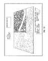
- FIG. 13illustrates an example visualized urban plan.
- FIG. 14is an illustration about children's education.
- FIG. 15is a conventional illustration about population density.
- visualizationsare just static illustrations. With the principles described herein, these can become live, interactive experiences. For instance, by inputting a geographically distributed growth pattern as input data, a user might see the population peaks change. Some visualizations, where the authored model supports this, will let users do what-ifs. That is, the author may change some values and see the effect on that change on other values.
- the principles described hereinprovide a major paradigm shift in the world of visualized problem solving and analysis.
- the paradigm shiftapplies across all domains as the principles described herein may apply to any domain.
- FIG. 16illustrates a computing system 1600 .
- Computing systemsare now increasingly taking a wide variety of forms. Computing systems may, for example, be handheld devices, appliances, laptop computers, desktop computers, mainframes, distributed computing systems, or even devices that have not conventionally considered a computing system.
- the term “computing system”is defined broadly as including any device or system (or combination thereof) that includes at least one processor, and a memory capable of having thereon computer-executable instructions that may be executed by the processor.
- the memorymay take any form and may depend on the nature and form of the computing system.
- a computing systemmay be distributed over a network environment and may include multiple constituent computing systems.
- a computing system 1600typically includes at least one processing unit 1602 and memory 1604 .
- the memory 1604may be physical system memory, which may be volatile, non-volatile, or some combination of the two.
- the term “memory”may also be used herein to refer to non-volatile mass storage such as physical storage media. If the computing system is distributed, the processing, memory and/or storage capability may be distributed as well.
- the term “module” or “component”can refer to software objects or routines that execute on the computing system. The different components, modules, engines, and services described herein may be implemented as objects or processes that execute on the computing system (e.g., as separate threads).
- embodimentsare described with reference to acts that are performed by one or more computing systems. If such acts are implemented in software, one or more processors of the associated computing system that performs the act direct the operation of the computing system in response to having executed computer-executable instructions.
- An example of such an operationinvolves the manipulation of data.
- the computer-executable instructions (and the manipulated data)may be stored in the memory 1604 of the computing system 1600 .
- Computing system 1600may also contain communication channels 1608 that allow the computing system 1600 to communicate with other message processors over, for example, network 1610 .
- Communication channels 1608are examples of communications media.
- Communications mediatypically embody computer-readable instructions, data structures, program modules, or other data in a modulated data signal such as a carrier wave or other transport mechanism and include any information-delivery media.
- communications mediainclude wired media, such as wired networks and direct-wired connections, and wireless media such as acoustic, radio, infrared, and other wireless media.
- the term computer-readable media as used hereinincludes both storage media and communications media.
- Embodiments within the scope of the present inventionalso include computer-readable media for carrying or having computer-executable instructions or data structures stored thereon.
- Such computer-readable mediacan be any available media that can be accessed by a general purpose or special purpose computer.
- Such computer-readable mediacan comprise physical storage and/or memory media such as RAM, ROM, EEPROM, CD-ROM or other optical disk storage, magnetic disk storage or other magnetic storage devices, or any other medium which can be used to carry or store desired program code means in the form of computer-executable instructions or data structures and which can be accessed by a general purpose or special purpose computer.
- Computer-executable instructionscomprise, for example, instructions and data which cause a general purpose computer, special purpose computer, or special purpose processing device to perform a certain function or group of functions.
Landscapes
- Engineering & Computer Science (AREA)
- Physics & Mathematics (AREA)
- General Physics & Mathematics (AREA)
- Theoretical Computer Science (AREA)
- Computer Graphics (AREA)
- Computer Hardware Design (AREA)
- General Engineering & Computer Science (AREA)
- Software Systems (AREA)
- Processing Or Creating Images (AREA)
- User Interface Of Digital Computer (AREA)
Abstract
Description
Claims (20)
Priority Applications (1)
| Application Number | Priority Date | Filing Date | Title |
|---|---|---|---|
| US12/163,867US8411085B2 (en) | 2008-06-27 | 2008-06-27 | Constructing view compositions for domain-specific environments |
Applications Claiming Priority (1)
| Application Number | Priority Date | Filing Date | Title |
|---|---|---|---|
| US12/163,867US8411085B2 (en) | 2008-06-27 | 2008-06-27 | Constructing view compositions for domain-specific environments |
Publications (2)
| Publication Number | Publication Date |
|---|---|
| US20090322743A1 US20090322743A1 (en) | 2009-12-31 |
| US8411085B2true US8411085B2 (en) | 2013-04-02 |
Family
ID=41446811
Family Applications (1)
| Application Number | Title | Priority Date | Filing Date |
|---|---|---|---|
| US12/163,867Expired - Fee RelatedUS8411085B2 (en) | 2008-06-27 | 2008-06-27 | Constructing view compositions for domain-specific environments |
Country Status (1)
| Country | Link |
|---|---|
| US (1) | US8411085B2 (en) |
Cited By (8)
| Publication number | Priority date | Publication date | Assignee | Title |
|---|---|---|---|---|
| US20120109661A1 (en)* | 2010-10-27 | 2012-05-03 | Sap Ag | Associative information linking for business objects |
| US9785987B2 (en) | 2010-04-22 | 2017-10-10 | Microsoft Technology Licensing, Llc | User interface for information presentation system |
| US20180173401A1 (en)* | 2015-06-01 | 2018-06-21 | Lg Electronics Inc. | Mobile terminal |
| US10061469B2 (en) | 2016-09-28 | 2018-08-28 | International Business Machines Corporation | Swivel bar concept within a 3D space to invite users to explore additional data on a third axis |
| US10068357B2 (en)* | 2016-09-28 | 2018-09-04 | International Business Machines Corporation | Graphical evaluation of a cognitive analysis using a 3D swivel bar chart |
| US10628504B2 (en) | 2010-07-30 | 2020-04-21 | Microsoft Technology Licensing, Llc | System of providing suggestions based on accessible and contextual information |
| US20200242849A1 (en)* | 2019-01-30 | 2020-07-30 | Lisa Cini | Methods and systems for rendering and modifying three-dimensional models for interior design |
| US11348126B2 (en) | 2018-01-15 | 2022-05-31 | The Nielsen Company (Us), Llc | Methods and apparatus for campaign mapping for total audience measurement |
Families Citing this family (23)
| Publication number | Priority date | Publication date | Assignee | Title |
|---|---|---|---|---|
| US8117145B2 (en) | 2008-06-27 | 2012-02-14 | Microsoft Corporation | Analytical model solver framework |
| US8255192B2 (en)* | 2008-06-27 | 2012-08-28 | Microsoft Corporation | Analytical map models |
| US8620635B2 (en) | 2008-06-27 | 2013-12-31 | Microsoft Corporation | Composition of analytics models |
| US8145615B2 (en)* | 2008-11-26 | 2012-03-27 | Microsoft Corporation | Search and exploration using analytics reference model |
| US8155931B2 (en)* | 2008-11-26 | 2012-04-10 | Microsoft Corporation | Use of taxonomized analytics reference model |
| US8103608B2 (en)* | 2008-11-26 | 2012-01-24 | Microsoft Corporation | Reference model for data-driven analytics |
| US8190406B2 (en)* | 2008-11-26 | 2012-05-29 | Microsoft Corporation | Hybrid solver for data-driven analytics |
| US8314793B2 (en) | 2008-12-24 | 2012-11-20 | Microsoft Corporation | Implied analytical reasoning and computation |
| US9330503B2 (en) | 2009-06-19 | 2016-05-03 | Microsoft Technology Licensing, Llc | Presaging and surfacing interactivity within data visualizations |
| US8692826B2 (en) | 2009-06-19 | 2014-04-08 | Brian C. Beckman | Solver-based visualization framework |
| US8866818B2 (en) | 2009-06-19 | 2014-10-21 | Microsoft Corporation | Composing shapes and data series in geometries |
| US8493406B2 (en) | 2009-06-19 | 2013-07-23 | Microsoft Corporation | Creating new charts and data visualizations |
| US8259134B2 (en)* | 2009-06-19 | 2012-09-04 | Microsoft Corporation | Data-driven model implemented with spreadsheets |
| US8531451B2 (en) | 2009-06-19 | 2013-09-10 | Microsoft Corporation | Data-driven visualization transformation |
| US8788574B2 (en) | 2009-06-19 | 2014-07-22 | Microsoft Corporation | Data-driven visualization of pseudo-infinite scenes |
| US8352397B2 (en) | 2009-09-10 | 2013-01-08 | Microsoft Corporation | Dependency graph in data-driven model |
| US20120102419A1 (en)* | 2010-10-22 | 2012-04-26 | Microsoft Corporation | Representing data through a graphical object |
| US8823711B2 (en) | 2010-12-17 | 2014-09-02 | Microsoft Corporation | Incremental creation of a graphical object to visually represent a data set |
| US10001385B2 (en) | 2014-06-26 | 2018-06-19 | Sang Jun Park | Online street safety map system displaying crime density and traffic accident data |
| USD825580S1 (en) | 2016-05-27 | 2018-08-14 | Adp, Llc | Display screen or portion thereof with graphical user interface |
| USD794667S1 (en) | 2016-05-27 | 2017-08-15 | Adp, Llc | Display screen or portion thereof with graphical user interface |
| USD794666S1 (en) | 2016-05-27 | 2017-08-15 | Adp, Llc | Display screen or portion thereof with graphical user interface |
| USD798892S1 (en)* | 2016-05-27 | 2017-10-03 | Adp, Llc | Display screen or portion thereof with animated graphical user interface |
Citations (192)
| Publication number | Priority date | Publication date | Assignee | Title |
|---|---|---|---|---|
| US5189633A (en) | 1990-01-12 | 1993-02-23 | Bonadio Allan R | Apparatus and method for interactively manipulating mathematical equations |
| US5469538A (en) | 1994-03-02 | 1995-11-21 | Mathsoft, Inc. | Mathematical document editor and method performing live symbolic calculations for use with an electronic book |
| US5481741A (en) | 1986-04-14 | 1996-01-02 | National Instruments Corporation | Method and apparatus for providing attribute nodes in a graphical data flow environment |
| US5491779A (en) | 1992-04-03 | 1996-02-13 | Bezjian; Richard D. | Three dimensional presentation of multiple data sets in unitary format with pie charts |
| US5528735A (en) | 1993-03-23 | 1996-06-18 | Silicon Graphics Inc. | Method and apparatus for displaying data within a three-dimensional information landscape |
| US5535385A (en) | 1995-05-19 | 1996-07-09 | At&T Corp. | Dealing with side effects of transactions in data base systems using a multi-set algebra |
| US5537618A (en) | 1993-12-23 | 1996-07-16 | Diacom Technologies, Inc. | Method and apparatus for implementing user feedback |
| US5555354A (en) | 1993-03-23 | 1996-09-10 | Silicon Graphics Inc. | Method and apparatus for navigation within three-dimensional information landscape |
| US5675746A (en) | 1992-09-30 | 1997-10-07 | Marshall; Paul S. | Virtual reality generator for use with financial information |
| US5732001A (en) | 1994-09-13 | 1998-03-24 | Sharp Kabushiki Kaisha | Calculator with stepwise display of linear equations |
| US5764241A (en) | 1995-11-30 | 1998-06-09 | Microsoft Corporation | Method and system for modeling and presenting integrated media with a declarative modeling language for representing reactive behavior |
| US5809499A (en) | 1995-10-20 | 1998-09-15 | Pattern Discovery Software Systems, Ltd. | Computational method for discovering patterns in data sets |
| US5818737A (en) | 1994-08-04 | 1998-10-06 | City Of Scottsdale | Method for guiding development of muncipality |
| US5874955A (en) | 1994-02-03 | 1999-02-23 | International Business Machines Corporation | Interactive rule based system with selection feedback that parameterizes rules to constrain choices for multiple operations |
| US5923324A (en) | 1997-04-04 | 1999-07-13 | International Business Machines Corporation | Viewer interactive three-dimensional workspace with interactive three-dimensional objects and corresponding two-dimensional images of objects in an interactive two-dimensional workplane |
| US5945976A (en) | 1991-11-14 | 1999-08-31 | Hitachi, Ltd. | Graphic data processing system |
| US6034697A (en) | 1997-01-13 | 2000-03-07 | Silicon Graphics, Inc. | Interpolation between relational tables for purposes of animating a data visualization |
| US6063126A (en) | 1997-12-04 | 2000-05-16 | Autodesk, Inc. | Modeling system having constraint solvers |
| US6085978A (en) | 1994-08-17 | 2000-07-11 | Metrologic Instruments, Inc. | Holographic laser scanners of modular construction and method and apparatus for designing and manufacturing the same |
| US6088698A (en) | 1998-02-27 | 2000-07-11 | Oracle Corporation | Method and apparatus for incrementally generating a virtual three-dimensional world |
| US6104410A (en) | 1997-01-17 | 2000-08-15 | Shui-Ying Wong | Method and apparatus for displaying stacked symbols to create a multi-dimensional view |
| US6175954B1 (en) | 1997-10-30 | 2001-01-16 | Fuji Xerox Co., Ltd. | Computer programming using tangible user interface where physical icons (phicons) indicate: beginning and end of statements and program constructs; statements generated with re-programmable phicons and stored |
| US6189012B1 (en) | 1998-01-23 | 2001-02-13 | Melting Point Limited | Apparatus and method for storing, navigating among and adding links between data items |
| US6208985B1 (en) | 1997-07-09 | 2001-03-27 | Caseventure Llc | Data refinery: a direct manipulation user interface for data querying with integrated qualitative and quantitative graphical representations of query construction and query result presentation |
| US6211887B1 (en) | 1998-05-28 | 2001-04-03 | Ericsson Inc | System and method for data visualization |
| US6222533B1 (en) | 1997-08-25 | 2001-04-24 | I2 Technologies, Inc. | System and process having a universal adapter framework and providing a global user interface and global messaging bus |
| US6239796B1 (en) | 1998-06-09 | 2001-05-29 | Agilent Technologies, Inc. | Apparatus and method for controlling dialog box display and system interactivity in a signal measurement system |
| US6260035B1 (en) | 1996-07-19 | 2001-07-10 | Microsoft Corporation | Intelligent user assistance facility for a software program |
| US6263339B1 (en) | 1998-08-25 | 2001-07-17 | Informix Software, Inc. | Dynamic object visualization and code generation |
| US6266053B1 (en) | 1998-04-03 | 2001-07-24 | Synapix, Inc. | Time inheritance scene graph for representation of media content |
| US6269325B1 (en) | 1998-10-21 | 2001-07-31 | Unica Technologies, Inc. | Visual presentation technique for data mining software |
| US6286017B1 (en) | 1995-02-22 | 2001-09-04 | EGILSSON áGUST SVERRIR | Graphical environment for managing and developing applications |
| US20010049695A1 (en) | 1998-10-20 | 2001-12-06 | Ed H. Chi | Visualization spreadsheet |
| US20020010571A1 (en) | 1999-02-17 | 2002-01-24 | Daniel William E. | Systems and methods for interactive virtual reality process control and simulation (IVRPCS) |
| US6385563B1 (en) | 1998-11-10 | 2002-05-07 | Autodesk, Inc. | Reusable design model and apparatus |
| US20020070953A1 (en) | 2000-05-04 | 2002-06-13 | Barg Timothy A. | Systems and methods for visualizing and analyzing conditioned data |
| US20020078086A1 (en) | 2000-12-18 | 2002-06-20 | Alden Jeffrey Morgan | Functional visualization of spreadsheets |
| US20020145623A1 (en) | 2000-05-16 | 2002-10-10 | Decombe Jean Michel | User interface for displaying and exploring hierarchical information |
| US20020169658A1 (en) | 2001-03-08 | 2002-11-14 | Adler Richard M. | System and method for modeling and analyzing strategic business decisions |
| US6484164B1 (en) | 2000-03-29 | 2002-11-19 | Koninklijke Philips Electronics N.V. | Data search user interface with ergonomic mechanism for user profile definition and manipulation |
| US20020183995A1 (en) | 2001-06-05 | 2002-12-05 | Alastair Veitch | System and method for simulating railroad rail testing |
| US6536037B1 (en) | 1999-05-27 | 2003-03-18 | Accenture Llp | Identification of redundancies and omissions among components of a web based architecture |
| US20030103089A1 (en) | 2001-09-07 | 2003-06-05 | Karthik Ramani | Systems and methods for collaborative shape design |
| US20030144868A1 (en) | 2001-10-11 | 2003-07-31 | Macintyre James W. | System, method, and computer program product for processing and visualization of information |
| US6639614B1 (en) | 2000-07-10 | 2003-10-28 | Stephen Michael Kosslyn | Multi-variate data presentation method using ecologically valid stimuli |
| US6647119B1 (en) | 1998-06-29 | 2003-11-11 | Microsoft Corporation | Spacialization of audio with visual cues |
| US6662146B1 (en) | 1998-11-25 | 2003-12-09 | Landmark Graphics Corporation | Methods for performing reservoir simulation |
| US20040015783A1 (en) | 2002-06-20 | 2004-01-22 | Canon Kabushiki Kaisha | Methods for interactively defining transforms and for generating queries by manipulating existing query data |
| US6687657B2 (en) | 2000-09-27 | 2004-02-03 | David N. Levin | Self-referential method and apparatus for creating stimulus representations that are invariant under systematic transformations of sensor states |
| US6690370B2 (en) | 1995-06-07 | 2004-02-10 | Geovector Corp. | Vision system computer modeling apparatus including interaction with real scenes with respect to perspective and spatial relationship as measured in real-time |
| US6707454B1 (en) | 1999-07-01 | 2004-03-16 | Lucent Technologies Inc. | Systems and methods for visualizing multi-dimensional data in spreadsheets and other data structures |
| US6714868B2 (en) | 2001-06-28 | 2004-03-30 | The United States Of America As Represented By The Secretary Of The Navy | Similarity transformation method for data processing and visualization |
| US6717599B1 (en) | 2000-06-29 | 2004-04-06 | Microsoft Corporation | Method, system, and computer program product for implementing derivative operators with graphics hardware |
| US20040075677A1 (en) | 2000-11-03 | 2004-04-22 | Loyall A. Bryan | Interactive character system |
| US20040075697A1 (en) | 2002-10-16 | 2004-04-22 | Maudlin Matthew Eric | Apparatus, system, method, and program for using GIS data |
| US20040080536A1 (en) | 2002-10-23 | 2004-04-29 | Zohar Yakhini | Method and user interface for interactive visualization and analysis of microarray data and other data, including genetic, biochemical, and chemical data |
| US20040114258A1 (en) | 2002-12-17 | 2004-06-17 | Harris Richard Alexander | Device and method for combining dynamic mathematical expressions and other multimedia objects within a document |
| US6753885B2 (en) | 2000-04-06 | 2004-06-22 | Microsoft Corporation | System and theme file format for creating visual styles |
| US20040154000A1 (en) | 2003-02-03 | 2004-08-05 | Kasra Kasravi | System and method for semantic software analysis |
| US20040189702A1 (en) | 2002-09-09 | 2004-09-30 | Michal Hlavac | Artificial intelligence platform |
| US20040196287A1 (en) | 2003-04-01 | 2004-10-07 | Wong Pak Chung | Dynamic visualization of data streams |
| US20040221855A1 (en) | 2002-10-17 | 2004-11-11 | Paul Ashton | Methods for monitoring treatment of disease |
| US6823299B1 (en) | 1999-07-09 | 2004-11-23 | Autodesk, Inc. | Modeling objects, systems, and simulations by establishing relationships in an event-driven graph in a computer implemented graphics system |
| US20040239494A1 (en) | 2003-05-14 | 2004-12-02 | Kennedy John F. | Systems and methods for automatic energy analysis of buildings |
| US20040246252A1 (en) | 2002-01-14 | 2004-12-09 | Morrow Jesse James | Method and apparatus for visualizing data |
| US6831603B2 (en) | 2002-03-12 | 2004-12-14 | Menache, Llc | Motion tracking system and method |
| US6836270B2 (en) | 2001-07-10 | 2004-12-28 | Geojet Information Solutions, Inc. | 3-D map data visualization |
| US6842175B1 (en) | 1999-04-22 | 2005-01-11 | Fraunhofer Usa, Inc. | Tools for interacting with virtual environments |
| US20050012743A1 (en) | 2003-03-15 | 2005-01-20 | Thomas Kapler | System and method for visualizing connected temporal and spatial information as an integrated visual representation on a user interface |
| US6856980B2 (en) | 2001-06-25 | 2005-02-15 | Exigen Group | Hybrid use of rule and constraint engines |
| US20050035883A1 (en) | 2003-08-01 | 2005-02-17 | Kenji Kameda | Map display system, map data processing apparatus, map display apparatus, and map display method |
| US6867788B1 (en) | 1998-07-15 | 2005-03-15 | International Business Machines Corporation | View composition system for synthesizing multiple visual representations of multiple data sets |
| US6868525B1 (en) | 2000-02-01 | 2005-03-15 | Alberti Anemometer Llc | Computer graphic display visualization system and method |
| US20050057560A1 (en)* | 2003-09-17 | 2005-03-17 | Viera Bibr | System and method for building wireless applications with intelligent mapping between user interface and data components |
| US20050091584A1 (en) | 2003-10-23 | 2005-04-28 | Microsoft Corporation | Methods for applying styles to visual aspects of user interface elements |
| US20050094207A1 (en) | 2003-10-15 | 2005-05-05 | Canon Kabushiki Kaisha | User interface for creation and editing of variable data documents |
| US20050108256A1 (en) | 2002-12-06 | 2005-05-19 | Attensity Corporation | Visualization of integrated structured and unstructured data |
| US20050120021A1 (en) | 2003-12-02 | 2005-06-02 | Microsoft Corporation | Metadata driven intelligent data navigation |
| US6906712B2 (en) | 2000-11-30 | 2005-06-14 | Solidworks Corporation | Automated three-dimensional alternative position viewer |
| US20050131659A1 (en) | 2003-12-16 | 2005-06-16 | Mei Hsaio L.S. | Systems and methods for 3D modeling and asset management |
| US20050131657A1 (en) | 2003-12-16 | 2005-06-16 | Sean Mei Hsaio L. | Systems and methods for 3D modeling and creation of a digital asset library |
| US20050137921A1 (en) | 2003-12-22 | 2005-06-23 | Shahriari Shahram P. | Method for evaluating the costs and benefits of environmental construction projects |
| US6912515B2 (en) | 2001-06-04 | 2005-06-28 | Xerox Corporation | Method and system for algorithm synthesis in problem solving |
| US6922681B2 (en) | 2001-12-20 | 2005-07-26 | Xerox Corporation | Problem partitioning method and system |
| US6928436B2 (en) | 2002-02-28 | 2005-08-09 | Ilog Sa | Interactive generation of graphical visualizations of large data structures |
| US6948154B1 (en) | 1999-03-22 | 2005-09-20 | Oregon State University | Methodology for testing spreadsheets |
| US20050210054A1 (en) | 2004-03-22 | 2005-09-22 | Michael Harris | Information management system |
| US6957191B1 (en) | 1999-02-05 | 2005-10-18 | Babcock & Brown Lp | Automated financial scenario modeling and analysis tool having an intelligent graphical user interface |
| US6959432B2 (en) | 2001-03-08 | 2005-10-25 | Escher Technologies, Ltd. | Process and system for developing mathematically validated object-oriented software |
| US6963824B1 (en) | 1999-02-19 | 2005-11-08 | Davidson Joseph K | Method and apparatus for geometric variations to integrate parametric computer aided design with tolerance analyses and optimization |
| US20050275622A1 (en) | 2004-06-14 | 2005-12-15 | Patel Himesh G | Computer-implemented system and method for defining graphics primitives |
| US6982712B2 (en) | 2002-03-27 | 2006-01-03 | Sony Corporation | Three-dimensional model generating system and method, and computer program therefor |
| US6983227B1 (en) | 1995-01-17 | 2006-01-03 | Intertech Ventures, Ltd. | Virtual models of complex systems |
| US6985623B2 (en) | 2002-06-10 | 2006-01-10 | Pts Corporation | Scene change detection by segmentation analysis |
| US20060020523A1 (en) | 2004-07-20 | 2006-01-26 | Song Michael K | Method and system for organizing and disseminating information on products featured in entertainment productions |
| US6995768B2 (en) | 2000-05-10 | 2006-02-07 | Cognos Incorporated | Interactive business data visualization system |
| US20060055696A1 (en) | 2004-08-17 | 2006-03-16 | Loberg Barrie A | Design software incorporating efficient 3-D rendering |
| US20060066632A1 (en) | 2004-09-30 | 2006-03-30 | Microsoft Corporation | Maintaining graphical presentations based on user customizations |
| US20060080594A1 (en) | 2004-10-07 | 2006-04-13 | Chavoustie Michael D | Methods, systems and computer program products for facilitating visualization of interrelationships in a spreadsheet |
| US7039569B1 (en) | 2000-06-09 | 2006-05-02 | Haws Richard R | Automatic adaptive dimensioning for CAD software |
| US7038680B2 (en) | 2002-01-09 | 2006-05-02 | Xerox Corporation | System for graphical display and interactive exploratory analysis of data and data relationships |
| US7047168B2 (en) | 2002-01-16 | 2006-05-16 | The Regents Of The University Of Michigan | Method and system for providing constraint-based guidance to a designer in a collaborative design environment |
| US20060106793A1 (en) | 2003-12-29 | 2006-05-18 | Ping Liang | Internet and computer information retrieval and mining with intelligent conceptual filtering, visualization and automation |
| US20060112123A1 (en) | 2004-11-24 | 2006-05-25 | Macnica, Inc. | Spreadsheet user-interfaced business data visualization and publishing system |
| US7055107B1 (en) | 2000-09-22 | 2006-05-30 | Wireless Valley Communications, Inc. | Method and system for automated selection of optimal communication network equipment model, position, and configuration |
| US20060117067A1 (en) | 2004-11-30 | 2006-06-01 | Oculus Info Inc. | System and method for interactive visual representation of information content and relationships using layout and gestures |
| US20060117303A1 (en) | 2004-11-24 | 2006-06-01 | Gizinski Gerard H | Method of simplifying & automating enhanced optimized decision making under uncertainty |
| US7058896B2 (en) | 2002-01-16 | 2006-06-06 | Silicon Graphics, Inc. | System, method and computer program product for intuitive interactive navigation control in virtual environments |
| US7089220B2 (en) | 2003-06-24 | 2006-08-08 | Palo Alto Research Center Incorporated | Complexity-directed cooperative problem solving |
| US7089221B2 (en) | 2003-06-24 | 2006-08-08 | Palo Alto Research Center Incorporated | Feedback control of problem solving |
| US7099890B2 (en) | 2001-01-05 | 2006-08-29 | Microsoft Corporation | Storing objects in a spreadsheet |
| US7102643B2 (en) | 2001-11-09 | 2006-09-05 | Vibe Solutions Group, Inc. | Method and apparatus for controlling the visual presentation of data |
| US7114127B2 (en) | 2002-03-28 | 2006-09-26 | International Business Machines Corporation | Method, system and program product in a model-view-controller (MVC) programming architecture for inter-object communication with transformation |
| US20060221077A1 (en) | 2005-03-08 | 2006-10-05 | William Wright | System and method for large scale information analysis using data visualization techniques |
| US20060253245A1 (en) | 2005-04-18 | 2006-11-09 | Cera Christopher D | Data-driven 3D traffic views with the view based on user-selected start and end geographical locations |
| US7139764B2 (en) | 2003-06-25 | 2006-11-21 | Lee Shih-Jong J | Dynamic learning and knowledge representation for data mining |
| US20060271581A1 (en) | 2005-05-12 | 2006-11-30 | International Business Machines Corporation | Simulation of computing system solutions based on customer data using a solution builder wizard environment |
| US20070005534A1 (en) | 2005-05-26 | 2007-01-04 | International Business Machines Corporation | Reformulation of constraint satisfaction problems for stochastic search |
| US20070011134A1 (en) | 2005-07-05 | 2007-01-11 | Justin Langseth | System and method of making unstructured data available to structured data analysis tools |
| US20070010901A1 (en) | 2004-01-21 | 2007-01-11 | Toshio Fukui | Constraint-based solution method, constraint-based solver and constraint-based solution system |
| US7165105B2 (en) | 2001-07-16 | 2007-01-16 | Netgenesis Corporation | System and method for logical view analysis and visualization of user behavior in a distributed computer network |
| US20070016873A1 (en) | 2005-07-15 | 2007-01-18 | Microsoft Corporation | Visual expression of a state of an application window |
| US20070033443A1 (en) | 2005-08-04 | 2007-02-08 | Microsoft Corporation | Unit test generalization |
| US20070043694A1 (en) | 2002-04-10 | 2007-02-22 | Sawafta Reyad I | System and method for data analysis, manipulation, and visualization |
| US7212200B2 (en) | 2001-11-28 | 2007-05-01 | Fujitsu Limited | Information processing device and data object display method |
| US7216116B1 (en) | 1996-05-06 | 2007-05-08 | Spotfire Ab | Data analysis system with automated query and visualization environment setup |
| US7219307B2 (en) | 2000-09-22 | 2007-05-15 | Jpmorgan Chase Bank | Methods for graphically representing interactions among entities |
| US20070136406A1 (en) | 2005-12-12 | 2007-06-14 | Softky William R | Method and system for numerical computation visualization |
| US20070141541A1 (en)* | 2005-12-13 | 2007-06-21 | Posit Science Corporation | Assessment in cognitive training exercises |
| US20070156677A1 (en) | 1999-07-21 | 2007-07-05 | Alberti Anemometer Llc | Database access system |
| US20070162866A1 (en) | 2006-01-09 | 2007-07-12 | Microsoft Corporation | Supporting user multi-tasking with clipping lists |
| US20070168454A1 (en) | 2006-01-19 | 2007-07-19 | International Business Machines Corporation | System and method for host-to-host communication |
| US7250951B1 (en) | 2002-04-10 | 2007-07-31 | Peter Hurley | System and method for visualizing data |
| US20070188494A1 (en)* | 2005-03-11 | 2007-08-16 | James Agutter | Systems and methods for displaying and querying heterogeneous sets of data |
| US7265752B2 (en) | 2004-01-09 | 2007-09-04 | Microsoft Corporation | Multi-chart geometry images |
| US7272815B1 (en) | 1999-05-17 | 2007-09-18 | Invensys Systems, Inc. | Methods and apparatus for control configuration with versioning, security, composite blocks, edit selection, object swapping, formulaic values and other aspects |
| US7272817B1 (en) | 2004-04-15 | 2007-09-18 | Bank Of America Corporation | Method and apparatus for modeling a business process to facilitate evaluation of driving metrics |
| US20070244910A1 (en) | 2006-04-12 | 2007-10-18 | Microsoft Corporation | Business process meta-model |
| US20070271207A1 (en) | 2006-05-18 | 2007-11-22 | Shady Copty | Determining Compliance Rates for Probabilistic Requests |
| US20070271508A1 (en) | 2001-10-15 | 2007-11-22 | Mathieu Audet | Information elements locating system and method |
| US20070277111A1 (en) | 2006-02-01 | 2007-11-29 | Wright State University | Graphical user interface using perception-action icons and a method thereof |
| US20070279416A1 (en) | 2006-06-06 | 2007-12-06 | Cobb Glenn A | Enabling and Rendering Business Components in an Interactive Data Visualization Tool |
| US20070282809A1 (en) | 2006-06-06 | 2007-12-06 | Orland Hoeber | Method and apparatus for concept-based visual |
| US20070294196A1 (en) | 2006-06-15 | 2007-12-20 | Microsoft Corporation | Computer method for solving sparse linear constraints |
| US20080010041A1 (en) | 2006-07-07 | 2008-01-10 | Siemens Technology-To-Business Center Llc | Assembling physical simulations in a 3D graphical editor |
| US20080015823A1 (en) | 2006-06-16 | 2008-01-17 | Tectonic Network, Inc. | Extensible building information model toolset |
| US7334222B2 (en) | 2002-09-11 | 2008-02-19 | International Business Machines Corporation | Methods and apparatus for dependency-based impact simulation and vulnerability analysis |
| US20080059889A1 (en) | 2006-09-01 | 2008-03-06 | Cheryl Parker | System and Method of Overlaying and Integrating Data with Geographic Mapping Applications |
| US20080062167A1 (en) | 2006-09-13 | 2008-03-13 | International Design And Construction Online, Inc. | Computer-based system and method for providing situational awareness for a structure using three-dimensional modeling |
| US7365311B1 (en) | 2005-09-08 | 2008-04-29 | The Mathworks, Inc. | Alignment of mass spectrometry data |
| US20080104118A1 (en) | 2006-10-26 | 2008-05-01 | Pulfer Charles E | Document classification toolbar |
| US20080115082A1 (en) | 2006-11-13 | 2008-05-15 | Simmons Hillery D | Knowledge discovery system |
| US20080115049A1 (en) | 2006-11-14 | 2008-05-15 | Microsoft Corporation | Dynamically generating mini-graphs to represent style and template icons |
| US20080133505A1 (en) | 2006-12-05 | 2008-06-05 | Yahoo! Inc. | Search results presented as visually illustrative concepts |
| US7392312B1 (en) | 1998-09-11 | 2008-06-24 | Lv Partners, L.P. | Method for utilizing visual cue in conjunction with web access |
| US20080192056A1 (en) | 2007-02-12 | 2008-08-14 | Microsoft Corporation | Animated transitions for data visualization |
| US20080221487A1 (en) | 2007-03-07 | 2008-09-11 | Motek Bv | Method for real time interactive visualization of muscle forces and joint torques in the human body |
| US20080218531A1 (en) | 2006-07-06 | 2008-09-11 | International Business Machines Corporation | System and method for visualization and interaction with spatial objects |
| US20080263468A1 (en) | 2007-04-17 | 2008-10-23 | Guava Technologies, Inc. | Graphical User Interface for Analysis and Comparison of Location-Specific Multiparameter Data Sets |
| US20090006318A1 (en) | 2007-06-29 | 2009-01-01 | Tobias Lehtipalo | Multi-source data visualization system |
| US20090013270A1 (en) | 2007-07-05 | 2009-01-08 | Oracle International Corporation | Linking graphical elements of data visualizations |
| US7486292B2 (en) | 2001-04-06 | 2009-02-03 | International Business Machines Corporation | Graph data visualization and graphics preparation |
| US20090094557A1 (en) | 2007-10-05 | 2009-04-09 | Autodesk, Inc. | Sun-shadow simulation in a geospatial system |
| US7559039B2 (en) | 1998-07-14 | 2009-07-07 | Brad Ridgley | Method and device for finding, collecting and acting upon units of information |
| US7574336B1 (en) | 2004-10-05 | 2009-08-11 | The Mathworks, Inc. | Model workspaces in modeling environments |
| US20090326919A1 (en)* | 2003-11-18 | 2009-12-31 | Bean David L | Acquisition and application of contextual role knowledge for coreference resolution |
| US20090326872A1 (en) | 2008-06-27 | 2009-12-31 | Microsoft Corporation | Analytical Map Models |
| US20090327183A1 (en) | 2008-06-27 | 2009-12-31 | Microsoft Corporation | Analytical model solver framework |
| US20090326885A1 (en) | 2008-06-27 | 2009-12-31 | Microsoft Corporation | Composition Of Analytics Models |
| US20090322739A1 (en) | 2008-06-27 | 2009-12-31 | Microsoft Corporation | Visual Interactions with Analytics |
| US20100100405A1 (en) | 2008-10-17 | 2010-04-22 | Green Wizard, Llc | Method and Apparatus for Determining and Managing Sustainability Ratings |
| US20100118026A1 (en) | 2008-11-07 | 2010-05-13 | Autodesk, Inc. | Method and apparatus for visualizing a quantity of a material used in a physical object having a plurality of physical elements |
| US20100131546A1 (en) | 2008-11-26 | 2010-05-27 | Microsoft Way | Search and exploration using analytics reference model |
| US20100131255A1 (en) | 2008-11-26 | 2010-05-27 | Microsoft Corporation | Hybrid solver for data-driven analytics |
| US20100131254A1 (en) | 2008-11-26 | 2010-05-27 | Microsoft Corporation | Use of taxonomized analytics reference model |
| US20100131248A1 (en) | 2008-11-26 | 2010-05-27 | Microsoft Corporation | Reference model for data-driven analytics |
| US20100156900A1 (en) | 2008-12-24 | 2010-06-24 | Microsoft Corporation | Implied analytical reasoning and computation |
| US7765175B2 (en) | 2003-09-18 | 2010-07-27 | Optimum Power Technology, L.P. | Optimization expert system |
| US7817150B2 (en) | 2005-09-30 | 2010-10-19 | Rockwell Automation Technologies, Inc. | Three-dimensional immersive system for representing an automation control environment |
| US20100325196A1 (en) | 2009-06-19 | 2010-12-23 | Microsoft Corporation | Data-driven visualization of pseudo-infinite scenes |
| US20100324870A1 (en) | 2009-06-19 | 2010-12-23 | Microsoft Corporation | Solver-based visualization framework |
| US20100321407A1 (en) | 2009-06-19 | 2010-12-23 | Microsoft Corporation | Data-driven model implemented with spreadsheets |
| US20100325578A1 (en) | 2009-06-19 | 2010-12-23 | Microsoft Corporation | Presaging and surfacing interactivity within data visualizations |
| US20100325564A1 (en) | 2009-06-19 | 2010-12-23 | Microsoft Corporation | Charts in virtual environments |
| US20100325166A1 (en) | 2009-06-19 | 2010-12-23 | Microsoft Corporation | Creating new charts and data visualizations |
| US20100324867A1 (en) | 2009-06-19 | 2010-12-23 | Microsoft Corporation | Data-driven visualization transformation |
| US20100321391A1 (en) | 2009-06-19 | 2010-12-23 | Microsoft Corporation | Composing shapes and data series in geometries |
| US7873946B2 (en) | 2006-03-23 | 2011-01-18 | Oracle America, Inc. | Scalable vector graphics, tree and tab as drag and drop objects |
| US20110060704A1 (en) | 2009-09-10 | 2011-03-10 | Microsoft Corporation | Dependency graph in data-driven model |
| US7912807B2 (en) | 2009-04-30 | 2011-03-22 | Integrated Environmental Solutions, Ltd. | Method and system for modeling energy efficient buildings using a plurality of synchronized workflows |
| US7965290B1 (en) | 2007-07-13 | 2011-06-21 | Ngrain (Canada) Corporation | Method, system, and data structure for progressive loading and processing of a 3D dataset |
| US7973786B2 (en) | 2007-01-16 | 2011-07-05 | Motorola Solutions, Inc. | System and method for managing interaction in a virtual environment |
Family Cites Families (1)
| Publication number | Priority date | Publication date | Assignee | Title |
|---|---|---|---|---|
| US20070055534A1 (en)* | 2005-08-24 | 2007-03-08 | Lau Wai Y | Method and system for implementing advertising and marketing campaign in electronic and computer devices |
- 2008
- 2008-06-27USUS12/163,867patent/US8411085B2/ennot_activeExpired - Fee Related
Patent Citations (196)
| Publication number | Priority date | Publication date | Assignee | Title |
|---|---|---|---|---|
| US5481741A (en) | 1986-04-14 | 1996-01-02 | National Instruments Corporation | Method and apparatus for providing attribute nodes in a graphical data flow environment |
| US5189633A (en) | 1990-01-12 | 1993-02-23 | Bonadio Allan R | Apparatus and method for interactively manipulating mathematical equations |
| US5945976A (en) | 1991-11-14 | 1999-08-31 | Hitachi, Ltd. | Graphic data processing system |
| US5491779A (en) | 1992-04-03 | 1996-02-13 | Bezjian; Richard D. | Three dimensional presentation of multiple data sets in unitary format with pie charts |
| US5675746A (en) | 1992-09-30 | 1997-10-07 | Marshall; Paul S. | Virtual reality generator for use with financial information |
| US6073115A (en) | 1992-09-30 | 2000-06-06 | Marshall; Paul Steven | Virtual reality generator for displaying abstract information |
| US5528735A (en) | 1993-03-23 | 1996-06-18 | Silicon Graphics Inc. | Method and apparatus for displaying data within a three-dimensional information landscape |
| US5555354A (en) | 1993-03-23 | 1996-09-10 | Silicon Graphics Inc. | Method and apparatus for navigation within three-dimensional information landscape |
| US5537618A (en) | 1993-12-23 | 1996-07-16 | Diacom Technologies, Inc. | Method and apparatus for implementing user feedback |
| US5874955A (en) | 1994-02-03 | 1999-02-23 | International Business Machines Corporation | Interactive rule based system with selection feedback that parameterizes rules to constrain choices for multiple operations |
| US5469538A (en) | 1994-03-02 | 1995-11-21 | Mathsoft, Inc. | Mathematical document editor and method performing live symbolic calculations for use with an electronic book |
| US5818737A (en) | 1994-08-04 | 1998-10-06 | City Of Scottsdale | Method for guiding development of muncipality |
| US6085978A (en) | 1994-08-17 | 2000-07-11 | Metrologic Instruments, Inc. | Holographic laser scanners of modular construction and method and apparatus for designing and manufacturing the same |
| US5732001A (en) | 1994-09-13 | 1998-03-24 | Sharp Kabushiki Kaisha | Calculator with stepwise display of linear equations |
| US6983227B1 (en) | 1995-01-17 | 2006-01-03 | Intertech Ventures, Ltd. | Virtual models of complex systems |
| US6286017B1 (en) | 1995-02-22 | 2001-09-04 | EGILSSON áGUST SVERRIR | Graphical environment for managing and developing applications |
| US5535385A (en) | 1995-05-19 | 1996-07-09 | At&T Corp. | Dealing with side effects of transactions in data base systems using a multi-set algebra |
| US6690370B2 (en) | 1995-06-07 | 2004-02-10 | Geovector Corp. | Vision system computer modeling apparatus including interaction with real scenes with respect to perspective and spatial relationship as measured in real-time |
| US5809499A (en) | 1995-10-20 | 1998-09-15 | Pattern Discovery Software Systems, Ltd. | Computational method for discovering patterns in data sets |
| US5764241A (en) | 1995-11-30 | 1998-06-09 | Microsoft Corporation | Method and system for modeling and presenting integrated media with a declarative modeling language for representing reactive behavior |
| US7216116B1 (en) | 1996-05-06 | 2007-05-08 | Spotfire Ab | Data analysis system with automated query and visualization environment setup |
| US6260035B1 (en) | 1996-07-19 | 2001-07-10 | Microsoft Corporation | Intelligent user assistance facility for a software program |
| US6034697A (en) | 1997-01-13 | 2000-03-07 | Silicon Graphics, Inc. | Interpolation between relational tables for purposes of animating a data visualization |
| US6104410A (en) | 1997-01-17 | 2000-08-15 | Shui-Ying Wong | Method and apparatus for displaying stacked symbols to create a multi-dimensional view |
| US5923324A (en) | 1997-04-04 | 1999-07-13 | International Business Machines Corporation | Viewer interactive three-dimensional workspace with interactive three-dimensional objects and corresponding two-dimensional images of objects in an interactive two-dimensional workplane |
| US6208985B1 (en) | 1997-07-09 | 2001-03-27 | Caseventure Llc | Data refinery: a direct manipulation user interface for data querying with integrated qualitative and quantitative graphical representations of query construction and query result presentation |
| US6222533B1 (en) | 1997-08-25 | 2001-04-24 | I2 Technologies, Inc. | System and process having a universal adapter framework and providing a global user interface and global messaging bus |
| US6175954B1 (en) | 1997-10-30 | 2001-01-16 | Fuji Xerox Co., Ltd. | Computer programming using tangible user interface where physical icons (phicons) indicate: beginning and end of statements and program constructs; statements generated with re-programmable phicons and stored |
| US6063126A (en) | 1997-12-04 | 2000-05-16 | Autodesk, Inc. | Modeling system having constraint solvers |
| US6189012B1 (en) | 1998-01-23 | 2001-02-13 | Melting Point Limited | Apparatus and method for storing, navigating among and adding links between data items |
| US6088698A (en) | 1998-02-27 | 2000-07-11 | Oracle Corporation | Method and apparatus for incrementally generating a virtual three-dimensional world |
| US6266053B1 (en) | 1998-04-03 | 2001-07-24 | Synapix, Inc. | Time inheritance scene graph for representation of media content |
| US6211887B1 (en) | 1998-05-28 | 2001-04-03 | Ericsson Inc | System and method for data visualization |
| US6239796B1 (en) | 1998-06-09 | 2001-05-29 | Agilent Technologies, Inc. | Apparatus and method for controlling dialog box display and system interactivity in a signal measurement system |
| US6647119B1 (en) | 1998-06-29 | 2003-11-11 | Microsoft Corporation | Spacialization of audio with visual cues |
| US7559039B2 (en) | 1998-07-14 | 2009-07-07 | Brad Ridgley | Method and device for finding, collecting and acting upon units of information |
| US6867788B1 (en) | 1998-07-15 | 2005-03-15 | International Business Machines Corporation | View composition system for synthesizing multiple visual representations of multiple data sets |
| US6263339B1 (en) | 1998-08-25 | 2001-07-17 | Informix Software, Inc. | Dynamic object visualization and code generation |
| US7392312B1 (en) | 1998-09-11 | 2008-06-24 | Lv Partners, L.P. | Method for utilizing visual cue in conjunction with web access |
| US20010049695A1 (en) | 1998-10-20 | 2001-12-06 | Ed H. Chi | Visualization spreadsheet |
| US6269325B1 (en) | 1998-10-21 | 2001-07-31 | Unica Technologies, Inc. | Visual presentation technique for data mining software |
| US6385563B1 (en) | 1998-11-10 | 2002-05-07 | Autodesk, Inc. | Reusable design model and apparatus |
| US6662146B1 (en) | 1998-11-25 | 2003-12-09 | Landmark Graphics Corporation | Methods for performing reservoir simulation |
| US6957191B1 (en) | 1999-02-05 | 2005-10-18 | Babcock & Brown Lp | Automated financial scenario modeling and analysis tool having an intelligent graphical user interface |
| US20020010571A1 (en) | 1999-02-17 | 2002-01-24 | Daniel William E. | Systems and methods for interactive virtual reality process control and simulation (IVRPCS) |
| US6963824B1 (en) | 1999-02-19 | 2005-11-08 | Davidson Joseph K | Method and apparatus for geometric variations to integrate parametric computer aided design with tolerance analyses and optimization |
| US6948154B1 (en) | 1999-03-22 | 2005-09-20 | Oregon State University | Methodology for testing spreadsheets |
| US6842175B1 (en) | 1999-04-22 | 2005-01-11 | Fraunhofer Usa, Inc. | Tools for interacting with virtual environments |
| US7272815B1 (en) | 1999-05-17 | 2007-09-18 | Invensys Systems, Inc. | Methods and apparatus for control configuration with versioning, security, composite blocks, edit selection, object swapping, formulaic values and other aspects |
| US6536037B1 (en) | 1999-05-27 | 2003-03-18 | Accenture Llp | Identification of redundancies and omissions among components of a web based architecture |
| US6707454B1 (en) | 1999-07-01 | 2004-03-16 | Lucent Technologies Inc. | Systems and methods for visualizing multi-dimensional data in spreadsheets and other data structures |
| US6823299B1 (en) | 1999-07-09 | 2004-11-23 | Autodesk, Inc. | Modeling objects, systems, and simulations by establishing relationships in an event-driven graph in a computer implemented graphics system |
| US20070156677A1 (en) | 1999-07-21 | 2007-07-05 | Alberti Anemometer Llc | Database access system |
| US7530020B2 (en) | 2000-02-01 | 2009-05-05 | Andrew J Szabo | Computer graphic display visualization system and method |
| US7574659B2 (en) | 2000-02-01 | 2009-08-11 | Andrew Szabo | Computer graphic display visualization system and method |
| US6868525B1 (en) | 2000-02-01 | 2005-03-15 | Alberti Anemometer Llc | Computer graphic display visualization system and method |
| US20060288023A1 (en) | 2000-02-01 | 2006-12-21 | Alberti Anemometer Llc | Computer graphic display visualization system and method |
| US6484164B1 (en) | 2000-03-29 | 2002-11-19 | Koninklijke Philips Electronics N.V. | Data search user interface with ergonomic mechanism for user profile definition and manipulation |
| US6753885B2 (en) | 2000-04-06 | 2004-06-22 | Microsoft Corporation | System and theme file format for creating visual styles |
| US20020070953A1 (en) | 2000-05-04 | 2002-06-13 | Barg Timothy A. | Systems and methods for visualizing and analyzing conditioned data |
| US6995768B2 (en) | 2000-05-10 | 2006-02-07 | Cognos Incorporated | Interactive business data visualization system |
| US20020145623A1 (en) | 2000-05-16 | 2002-10-10 | Decombe Jean Michel | User interface for displaying and exploring hierarchical information |
| US7039569B1 (en) | 2000-06-09 | 2006-05-02 | Haws Richard R | Automatic adaptive dimensioning for CAD software |
| US6717599B1 (en) | 2000-06-29 | 2004-04-06 | Microsoft Corporation | Method, system, and computer program product for implementing derivative operators with graphics hardware |
| US6639614B1 (en) | 2000-07-10 | 2003-10-28 | Stephen Michael Kosslyn | Multi-variate data presentation method using ecologically valid stimuli |
| US7219307B2 (en) | 2000-09-22 | 2007-05-15 | Jpmorgan Chase Bank | Methods for graphically representing interactions among entities |
| US7055107B1 (en) | 2000-09-22 | 2006-05-30 | Wireless Valley Communications, Inc. | Method and system for automated selection of optimal communication network equipment model, position, and configuration |
| US6687657B2 (en) | 2000-09-27 | 2004-02-03 | David N. Levin | Self-referential method and apparatus for creating stimulus representations that are invariant under systematic transformations of sensor states |
| US20040075677A1 (en) | 2000-11-03 | 2004-04-22 | Loyall A. Bryan | Interactive character system |
| US6906712B2 (en) | 2000-11-30 | 2005-06-14 | Solidworks Corporation | Automated three-dimensional alternative position viewer |
| US20020078086A1 (en) | 2000-12-18 | 2002-06-20 | Alden Jeffrey Morgan | Functional visualization of spreadsheets |
| US7099890B2 (en) | 2001-01-05 | 2006-08-29 | Microsoft Corporation | Storing objects in a spreadsheet |
| US6959432B2 (en) | 2001-03-08 | 2005-10-25 | Escher Technologies, Ltd. | Process and system for developing mathematically validated object-oriented software |
| US20020169658A1 (en) | 2001-03-08 | 2002-11-14 | Adler Richard M. | System and method for modeling and analyzing strategic business decisions |
| US7486292B2 (en) | 2001-04-06 | 2009-02-03 | International Business Machines Corporation | Graph data visualization and graphics preparation |
| US6912515B2 (en) | 2001-06-04 | 2005-06-28 | Xerox Corporation | Method and system for algorithm synthesis in problem solving |
| US20020183995A1 (en) | 2001-06-05 | 2002-12-05 | Alastair Veitch | System and method for simulating railroad rail testing |
| US6856980B2 (en) | 2001-06-25 | 2005-02-15 | Exigen Group | Hybrid use of rule and constraint engines |
| US6714868B2 (en) | 2001-06-28 | 2004-03-30 | The United States Of America As Represented By The Secretary Of The Navy | Similarity transformation method for data processing and visualization |
| US6836270B2 (en) | 2001-07-10 | 2004-12-28 | Geojet Information Solutions, Inc. | 3-D map data visualization |
| US7165105B2 (en) | 2001-07-16 | 2007-01-16 | Netgenesis Corporation | System and method for logical view analysis and visualization of user behavior in a distributed computer network |
| US20030103089A1 (en) | 2001-09-07 | 2003-06-05 | Karthik Ramani | Systems and methods for collaborative shape design |
| US20030144868A1 (en) | 2001-10-11 | 2003-07-31 | Macintyre James W. | System, method, and computer program product for processing and visualization of information |
| US20070271508A1 (en) | 2001-10-15 | 2007-11-22 | Mathieu Audet | Information elements locating system and method |
| US7102643B2 (en) | 2001-11-09 | 2006-09-05 | Vibe Solutions Group, Inc. | Method and apparatus for controlling the visual presentation of data |
| US7212200B2 (en) | 2001-11-28 | 2007-05-01 | Fujitsu Limited | Information processing device and data object display method |
| US6922681B2 (en) | 2001-12-20 | 2005-07-26 | Xerox Corporation | Problem partitioning method and system |
| US7038680B2 (en) | 2002-01-09 | 2006-05-02 | Xerox Corporation | System for graphical display and interactive exploratory analysis of data and data relationships |
| US20040246252A1 (en) | 2002-01-14 | 2004-12-09 | Morrow Jesse James | Method and apparatus for visualizing data |
| US7058896B2 (en) | 2002-01-16 | 2006-06-06 | Silicon Graphics, Inc. | System, method and computer program product for intuitive interactive navigation control in virtual environments |
| US7047168B2 (en) | 2002-01-16 | 2006-05-16 | The Regents Of The University Of Michigan | Method and system for providing constraint-based guidance to a designer in a collaborative design environment |
| US6928436B2 (en) | 2002-02-28 | 2005-08-09 | Ilog Sa | Interactive generation of graphical visualizations of large data structures |
| US6831603B2 (en) | 2002-03-12 | 2004-12-14 | Menache, Llc | Motion tracking system and method |
| US6982712B2 (en) | 2002-03-27 | 2006-01-03 | Sony Corporation | Three-dimensional model generating system and method, and computer program therefor |
| US7114127B2 (en) | 2002-03-28 | 2006-09-26 | International Business Machines Corporation | Method, system and program product in a model-view-controller (MVC) programming architecture for inter-object communication with transformation |
| US7250951B1 (en) | 2002-04-10 | 2007-07-31 | Peter Hurley | System and method for visualizing data |
| US20070043694A1 (en) | 2002-04-10 | 2007-02-22 | Sawafta Reyad I | System and method for data analysis, manipulation, and visualization |
| US6985623B2 (en) | 2002-06-10 | 2006-01-10 | Pts Corporation | Scene change detection by segmentation analysis |
| US20040015783A1 (en) | 2002-06-20 | 2004-01-22 | Canon Kabushiki Kaisha | Methods for interactively defining transforms and for generating queries by manipulating existing query data |
| US20040189702A1 (en) | 2002-09-09 | 2004-09-30 | Michal Hlavac | Artificial intelligence platform |
| US7334222B2 (en) | 2002-09-11 | 2008-02-19 | International Business Machines Corporation | Methods and apparatus for dependency-based impact simulation and vulnerability analysis |
| US20040075697A1 (en) | 2002-10-16 | 2004-04-22 | Maudlin Matthew Eric | Apparatus, system, method, and program for using GIS data |
| US20040221855A1 (en) | 2002-10-17 | 2004-11-11 | Paul Ashton | Methods for monitoring treatment of disease |
| US20040080536A1 (en) | 2002-10-23 | 2004-04-29 | Zohar Yakhini | Method and user interface for interactive visualization and analysis of microarray data and other data, including genetic, biochemical, and chemical data |
| US20050108256A1 (en) | 2002-12-06 | 2005-05-19 | Attensity Corporation | Visualization of integrated structured and unstructured data |
| US20040114258A1 (en) | 2002-12-17 | 2004-06-17 | Harris Richard Alexander | Device and method for combining dynamic mathematical expressions and other multimedia objects within a document |
| US20040154000A1 (en) | 2003-02-03 | 2004-08-05 | Kasra Kasravi | System and method for semantic software analysis |
| US20050012743A1 (en) | 2003-03-15 | 2005-01-20 | Thomas Kapler | System and method for visualizing connected temporal and spatial information as an integrated visual representation on a user interface |
| US20040196287A1 (en) | 2003-04-01 | 2004-10-07 | Wong Pak Chung | Dynamic visualization of data streams |
| US20040239494A1 (en) | 2003-05-14 | 2004-12-02 | Kennedy John F. | Systems and methods for automatic energy analysis of buildings |
| US7089220B2 (en) | 2003-06-24 | 2006-08-08 | Palo Alto Research Center Incorporated | Complexity-directed cooperative problem solving |
| US7089221B2 (en) | 2003-06-24 | 2006-08-08 | Palo Alto Research Center Incorporated | Feedback control of problem solving |
| US7139764B2 (en) | 2003-06-25 | 2006-11-21 | Lee Shih-Jong J | Dynamic learning and knowledge representation for data mining |
| US20050035883A1 (en) | 2003-08-01 | 2005-02-17 | Kenji Kameda | Map display system, map data processing apparatus, map display apparatus, and map display method |
| US20050057560A1 (en)* | 2003-09-17 | 2005-03-17 | Viera Bibr | System and method for building wireless applications with intelligent mapping between user interface and data components |
| US7765175B2 (en) | 2003-09-18 | 2010-07-27 | Optimum Power Technology, L.P. | Optimization expert system |
| US20050094207A1 (en) | 2003-10-15 | 2005-05-05 | Canon Kabushiki Kaisha | User interface for creation and editing of variable data documents |
| US20050091584A1 (en) | 2003-10-23 | 2005-04-28 | Microsoft Corporation | Methods for applying styles to visual aspects of user interface elements |
| US20090326919A1 (en)* | 2003-11-18 | 2009-12-31 | Bean David L | Acquisition and application of contextual role knowledge for coreference resolution |
| US20050120021A1 (en) | 2003-12-02 | 2005-06-02 | Microsoft Corporation | Metadata driven intelligent data navigation |
| US20050131657A1 (en) | 2003-12-16 | 2005-06-16 | Sean Mei Hsaio L. | Systems and methods for 3D modeling and creation of a digital asset library |
| US20050131659A1 (en) | 2003-12-16 | 2005-06-16 | Mei Hsaio L.S. | Systems and methods for 3D modeling and asset management |
| US20050137921A1 (en) | 2003-12-22 | 2005-06-23 | Shahriari Shahram P. | Method for evaluating the costs and benefits of environmental construction projects |
| US20060106793A1 (en) | 2003-12-29 | 2006-05-18 | Ping Liang | Internet and computer information retrieval and mining with intelligent conceptual filtering, visualization and automation |
| US7265752B2 (en) | 2004-01-09 | 2007-09-04 | Microsoft Corporation | Multi-chart geometry images |
| US20070010901A1 (en) | 2004-01-21 | 2007-01-11 | Toshio Fukui | Constraint-based solution method, constraint-based solver and constraint-based solution system |
| US20050210054A1 (en) | 2004-03-22 | 2005-09-22 | Michael Harris | Information management system |
| US7272817B1 (en) | 2004-04-15 | 2007-09-18 | Bank Of America Corporation | Method and apparatus for modeling a business process to facilitate evaluation of driving metrics |
| US20050275622A1 (en) | 2004-06-14 | 2005-12-15 | Patel Himesh G | Computer-implemented system and method for defining graphics primitives |
| US20060020523A1 (en) | 2004-07-20 | 2006-01-26 | Song Michael K | Method and system for organizing and disseminating information on products featured in entertainment productions |
| US20060055696A1 (en) | 2004-08-17 | 2006-03-16 | Loberg Barrie A | Design software incorporating efficient 3-D rendering |
| US20060066632A1 (en) | 2004-09-30 | 2006-03-30 | Microsoft Corporation | Maintaining graphical presentations based on user customizations |
| US7574336B1 (en) | 2004-10-05 | 2009-08-11 | The Mathworks, Inc. | Model workspaces in modeling environments |
| US20060080594A1 (en) | 2004-10-07 | 2006-04-13 | Chavoustie Michael D | Methods, systems and computer program products for facilitating visualization of interrelationships in a spreadsheet |
| US20060117303A1 (en) | 2004-11-24 | 2006-06-01 | Gizinski Gerard H | Method of simplifying & automating enhanced optimized decision making under uncertainty |
| US20060112123A1 (en) | 2004-11-24 | 2006-05-25 | Macnica, Inc. | Spreadsheet user-interfaced business data visualization and publishing system |
| US20060117067A1 (en) | 2004-11-30 | 2006-06-01 | Oculus Info Inc. | System and method for interactive visual representation of information content and relationships using layout and gestures |
| US20060221077A1 (en) | 2005-03-08 | 2006-10-05 | William Wright | System and method for large scale information analysis using data visualization techniques |
| US20070188494A1 (en)* | 2005-03-11 | 2007-08-16 | James Agutter | Systems and methods for displaying and querying heterogeneous sets of data |
| US20060253245A1 (en) | 2005-04-18 | 2006-11-09 | Cera Christopher D | Data-driven 3D traffic views with the view based on user-selected start and end geographical locations |
| US20060271581A1 (en) | 2005-05-12 | 2006-11-30 | International Business Machines Corporation | Simulation of computing system solutions based on customer data using a solution builder wizard environment |
| US20070005534A1 (en) | 2005-05-26 | 2007-01-04 | International Business Machines Corporation | Reformulation of constraint satisfaction problems for stochastic search |
| US20070011134A1 (en) | 2005-07-05 | 2007-01-11 | Justin Langseth | System and method of making unstructured data available to structured data analysis tools |
| US20070016873A1 (en) | 2005-07-15 | 2007-01-18 | Microsoft Corporation | Visual expression of a state of an application window |
| US20070033443A1 (en) | 2005-08-04 | 2007-02-08 | Microsoft Corporation | Unit test generalization |
| US7365311B1 (en) | 2005-09-08 | 2008-04-29 | The Mathworks, Inc. | Alignment of mass spectrometry data |
| US7817150B2 (en) | 2005-09-30 | 2010-10-19 | Rockwell Automation Technologies, Inc. | Three-dimensional immersive system for representing an automation control environment |
| US20070136406A1 (en) | 2005-12-12 | 2007-06-14 | Softky William R | Method and system for numerical computation visualization |
| US20070141541A1 (en)* | 2005-12-13 | 2007-06-21 | Posit Science Corporation | Assessment in cognitive training exercises |
| US20070162866A1 (en) | 2006-01-09 | 2007-07-12 | Microsoft Corporation | Supporting user multi-tasking with clipping lists |
| US20070168454A1 (en) | 2006-01-19 | 2007-07-19 | International Business Machines Corporation | System and method for host-to-host communication |
| US20070277111A1 (en) | 2006-02-01 | 2007-11-29 | Wright State University | Graphical user interface using perception-action icons and a method thereof |
| US7873946B2 (en) | 2006-03-23 | 2011-01-18 | Oracle America, Inc. | Scalable vector graphics, tree and tab as drag and drop objects |
| US20070244910A1 (en) | 2006-04-12 | 2007-10-18 | Microsoft Corporation | Business process meta-model |
| US20070271207A1 (en) | 2006-05-18 | 2007-11-22 | Shady Copty | Determining Compliance Rates for Probabilistic Requests |
| US20070282809A1 (en) | 2006-06-06 | 2007-12-06 | Orland Hoeber | Method and apparatus for concept-based visual |
| US20070279416A1 (en) | 2006-06-06 | 2007-12-06 | Cobb Glenn A | Enabling and Rendering Business Components in an Interactive Data Visualization Tool |
| US20070294196A1 (en) | 2006-06-15 | 2007-12-20 | Microsoft Corporation | Computer method for solving sparse linear constraints |
| US20080015823A1 (en) | 2006-06-16 | 2008-01-17 | Tectonic Network, Inc. | Extensible building information model toolset |
| US20080218531A1 (en) | 2006-07-06 | 2008-09-11 | International Business Machines Corporation | System and method for visualization and interaction with spatial objects |
| US20080010041A1 (en) | 2006-07-07 | 2008-01-10 | Siemens Technology-To-Business Center Llc | Assembling physical simulations in a 3D graphical editor |
| US20080059889A1 (en) | 2006-09-01 | 2008-03-06 | Cheryl Parker | System and Method of Overlaying and Integrating Data with Geographic Mapping Applications |
| US20080062167A1 (en) | 2006-09-13 | 2008-03-13 | International Design And Construction Online, Inc. | Computer-based system and method for providing situational awareness for a structure using three-dimensional modeling |
| US20080104118A1 (en) | 2006-10-26 | 2008-05-01 | Pulfer Charles E | Document classification toolbar |
| US20080115082A1 (en) | 2006-11-13 | 2008-05-15 | Simmons Hillery D | Knowledge discovery system |
| US20080115049A1 (en) | 2006-11-14 | 2008-05-15 | Microsoft Corporation | Dynamically generating mini-graphs to represent style and template icons |
| US20080133505A1 (en) | 2006-12-05 | 2008-06-05 | Yahoo! Inc. | Search results presented as visually illustrative concepts |
| US7973786B2 (en) | 2007-01-16 | 2011-07-05 | Motorola Solutions, Inc. | System and method for managing interaction in a virtual environment |
| US20080192056A1 (en) | 2007-02-12 | 2008-08-14 | Microsoft Corporation | Animated transitions for data visualization |
| US20080221487A1 (en) | 2007-03-07 | 2008-09-11 | Motek Bv | Method for real time interactive visualization of muscle forces and joint torques in the human body |
| US20080263468A1 (en) | 2007-04-17 | 2008-10-23 | Guava Technologies, Inc. | Graphical User Interface for Analysis and Comparison of Location-Specific Multiparameter Data Sets |
| US20090006318A1 (en) | 2007-06-29 | 2009-01-01 | Tobias Lehtipalo | Multi-source data visualization system |
| US20090013270A1 (en) | 2007-07-05 | 2009-01-08 | Oracle International Corporation | Linking graphical elements of data visualizations |
| US7965290B1 (en) | 2007-07-13 | 2011-06-21 | Ngrain (Canada) Corporation | Method, system, and data structure for progressive loading and processing of a 3D dataset |
| US20090094557A1 (en) | 2007-10-05 | 2009-04-09 | Autodesk, Inc. | Sun-shadow simulation in a geospatial system |
| US20090322739A1 (en) | 2008-06-27 | 2009-12-31 | Microsoft Corporation | Visual Interactions with Analytics |
| US20090326885A1 (en) | 2008-06-27 | 2009-12-31 | Microsoft Corporation | Composition Of Analytics Models |
| US20090327183A1 (en) | 2008-06-27 | 2009-12-31 | Microsoft Corporation | Analytical model solver framework |
| US20090326872A1 (en) | 2008-06-27 | 2009-12-31 | Microsoft Corporation | Analytical Map Models |
| US20100100405A1 (en) | 2008-10-17 | 2010-04-22 | Green Wizard, Llc | Method and Apparatus for Determining and Managing Sustainability Ratings |
| US20100118026A1 (en) | 2008-11-07 | 2010-05-13 | Autodesk, Inc. | Method and apparatus for visualizing a quantity of a material used in a physical object having a plurality of physical elements |
| US20100131255A1 (en) | 2008-11-26 | 2010-05-27 | Microsoft Corporation | Hybrid solver for data-driven analytics |
| US20100131248A1 (en) | 2008-11-26 | 2010-05-27 | Microsoft Corporation | Reference model for data-driven analytics |
| US20100131546A1 (en) | 2008-11-26 | 2010-05-27 | Microsoft Way | Search and exploration using analytics reference model |
| US20100131254A1 (en) | 2008-11-26 | 2010-05-27 | Microsoft Corporation | Use of taxonomized analytics reference model |
| US20100156900A1 (en) | 2008-12-24 | 2010-06-24 | Microsoft Corporation | Implied analytical reasoning and computation |
| US7912807B2 (en) | 2009-04-30 | 2011-03-22 | Integrated Environmental Solutions, Ltd. | Method and system for modeling energy efficient buildings using a plurality of synchronized workflows |
| US20100321407A1 (en) | 2009-06-19 | 2010-12-23 | Microsoft Corporation | Data-driven model implemented with spreadsheets |
| US20100325166A1 (en) | 2009-06-19 | 2010-12-23 | Microsoft Corporation | Creating new charts and data visualizations |
| US20100324867A1 (en) | 2009-06-19 | 2010-12-23 | Microsoft Corporation | Data-driven visualization transformation |
| US20100321391A1 (en) | 2009-06-19 | 2010-12-23 | Microsoft Corporation | Composing shapes and data series in geometries |
| US20100325564A1 (en) | 2009-06-19 | 2010-12-23 | Microsoft Corporation | Charts in virtual environments |
| US20100325578A1 (en) | 2009-06-19 | 2010-12-23 | Microsoft Corporation | Presaging and surfacing interactivity within data visualizations |
| US20100324870A1 (en) | 2009-06-19 | 2010-12-23 | Microsoft Corporation | Solver-based visualization framework |
| US20100325196A1 (en) | 2009-06-19 | 2010-12-23 | Microsoft Corporation | Data-driven visualization of pseudo-infinite scenes |
| US20110060704A1 (en) | 2009-09-10 | 2011-03-10 | Microsoft Corporation | Dependency graph in data-driven model |
Non-Patent Citations (136)
| Title |
|---|
| "3D Landscape Design & Visualization Software," 3D Nature, http://3dnature.com/ (2008). |
| "About SAGA GIS," SAGA, www.saga-gis.uni-goettingen.de/html/index.php (Aug. 1, 2008). |
| "ChemSite 3D Molecular Visualization Software," Chemistry Software, www.chemistry-software.com/modelling/10190.htm (Aug. 1, 2008). |
| "ExSched: Solving Constraint Satisfaction Problems with the Spreadsheet Paradigm (11 pages) http://arxiv.org/ftp/cs/papers/0701/0701109.pdf". |
| "GIS Modeling," Clark Labs, www.clarklabs.org/products/GIS-Modeling.cfm (2006). |
| "Maplesoft Enhances Math Software," Maplesoft, www.automation.com/content/maplesoft-enhances-math-software, Aug. 26, 2008. |
| "Math Package Gives you Extensive Range of Symbolic and Numerical Capabilities," CNET Networks Inc, http://findarticles.com/p/articles/mi-hb4804/is-198907/ai-n17443817, Aug. 26, 2008. |
| "MATLAB," Research Services, Information Technology Services, www.bc.edu/offices/researchservices/software/Matlab.html, Mar. 2007. |
| "Plug-in Architecture of Constraint Hierarchy Solvers1 (11 pages) http://citeseerist.psu.edu/cache/papers/cs/12565/http:zSzzSzkti.ms.mff.cuni.czzSz~bartakzSzhtmlzSz..zSzdownloadszSzPlugIn.pdf/bartak97plug.pdf". |
| "Plug-in Architecture of Constraint Hierarchy Solvers1 (11 pages) http://citeseerist.psu.edu/cache/papers/cs/12565/http:zSzzSzkti.ms.mff.cuni.czzSz˜bartakzSzhtmlzSz..zSzdownloadszSzPlugIn.pdf/bartak97plug.pdf". |
| "SchematicSolver," Mathematica Application, www.SchematicSolver.com, (accessed Aug. 26, 2008). |
| "Solid Edge User's Guide Version 8" by Unigraphics Solutions, copyright in 2000.* |
| "Solver Platform SDK-Solver Engines (4 pages) http://www.solver.com/sdkengines.htm". |
| "System Structure Analysis: Clustering with Data Bindings (9 pages) http://ieeexplore.ieee.org/iel5/32/35878/01702084.pdf(IEEE Transactions on Software Engineering, vol. SE-11, No. 8, Aug. 1985)". |
| "TIBCO Spoffire DecisionSite Enterprise Analytics Product Suite," TIBCO Software Inc., http://spotfire.tibco.com/products/decisionsite.cfm, Aug. 26, 2008. |
| "Tube Map: Evaluation of a Visual Metaphor for Interfunctional Communication of Complex Projects (8 pages)http://know-center.tugraz.at/previous/i-know04/papers/burkhard.pdf(Graz, Austria, Jun. 30-Jul. 2, 2004)". |
| "Visual Metaphors for Database Exploration1 (13 pages) http://citeseer.ist.psu.edu/cache/papers/cs/5732/http:zSzzSzwww.darmstadt.gmd.dezSzoasyszSzprojectszSzvirgiliozSzvirgilio.pdf/levialdi95visual.pdf". |
| "Visualizing Software Changes (17 pages) http://ieeexplore.ieee.org/iel5/32/21473/00995435.pdf?isnumber=21473&prod=STD&arnumber=995435&arnumber=995435&arSt=396&ared=412&arAuthor=Eick%2C+S.G.%3B+Graves%2C+T.L.%3B+Karr%2C+A.F.%3B+Mockus%2C+A.%3B+Schuster%2C+P.(IEEE Transactions on Software Engineering, vol. 28, No. 4, Apr. 2002)". |
| 3D Representations for Software Visualization http://www.cs.wayne.edu/~vip/publications/Marcus.SoftVis.2003.3DRepresentation.pdf (10 pages). |
| 3D Representations for Software Visualization http://www.cs.wayne.edu/˜vip/publications/Marcus.SoftVis.2003.3DRepresentation.pdf (10 pages). |
| Andrew Vande Moere, Time-Varying Data Visualization Using Information Flocking Boids, IEEE Symposium, Austin, Texas Oct. 10-12, 2004, (8 pages). |
| Andy Yeh, VRMath: Knowledge Construction of 3D Geometry in Virtual Reality Microworlds, Published 2004, (2 pages). |
| Ansoft, "HFSS: User's Guide Version 10", Jun. 21, 2005, Ansoft Corporation. |
| Anthropomorphic Visualization: A New Approach for Depicting Participants in Online Spaces (4 pages) http://smg.media.mit.edu/papers/Perry/lb270-perry.PDF (Apr. 24-29, 2004). |
| Author Unknown, Broader Perspective, Feb. 10, 2008 (5 pages). |
| Author Unknown, Implicit Equations in MML, Mar. 3, 2008 (7 pages). |
| Author Unknown, Solving Systems of Equations, Oct. 16, 2002 (9 pages). |
| Author Unknown, Turning Data into Decisions, Copyright 2004, (2 pages) (Month of Publication is irrelevant since the year of Publication is clearly prior to the year of Application.). |
| Author Unknown, What Is SpeedTreeMax?, Published 2005, (2 pages) (Month of Publication is irrelevant since the year of Publication is clearly prior to the year of Application.). |
| Avin Mittal, Equational Reasoning, Dec. 1, 2005 (4 pages). |
| Bederson et al., Toolkit Design for Interactive Structured Graphics Aug. 2004 (12 pages). |
| Brook, Russell, "Solid Edge Design Sensors (On the Edge Solid Edge Tutorial)", Apr. 1, 2008, 4 pages. |
| Brook, Russell, "Solid Edge's Goal Seek: The Next Best Thing to Hindsight (On the Edge Solid Edge Tutorial)", Oct. 1, 2007, 3 pages, accessed at http://www.cadalyst.com/manufacturing/solid-edge039s-goal-seek-the-next-best-thing-hindsight-on-edge-solid-edge-tutorial-111. |
| Brook, Russell, "Supply Chain Collaboration (On the Edge Solid Edge Tutorial)", Jan. 1, 2007, 7 pages. |
| Browsing Large Online Data Tables using Generalized Query Previews (24 pages) hcil.cs.umd.edu/trs/2001-13/2001-13.ps (Feb. 5, 2002). |
| Bunus, Peter, "A Simulation and Decision Framework for Selection of Numerical Solvers in Scientific Computing," Linkoping University, Sweden, Aug. 2006. |
| Chen, Hong, "Towards Design Patterns for Dynamic Analytical Data Visualization," Analytical Solutions Division, SAS Institute Inc., 2004. |
| Chi, Ed H., "A Taxonomy of Visualization Techniques using the Data State Reference Model," Xerox Palo Alto Research Center, 2000. |
| Christophe Jermann et al., "A Constraint Programming Approach for Solving Rigid Geometric Systems", Published: 2000, pp. 233-248. ((Month of publication is irrelevant since the year of publication is clearly prior to the filing of the Application). |
| Claude Kirchner, Constrained Equational Reasoning, 1989 ACM, (8 pages) (Month of Publication is irrelevant since the year of publication is clearly prior to the year of Application). |
| David A. Plaisted, Equational Reasoning and Term Rewriting Systems, Published: 1993,(83 pages) (Month of Publication is irrelevant since the year of publication is clearly prior to the year of Application). |
| DUST 1.5: Interactive Data Visualization Apr. 2000 (1 page). |
| Ebert et al., Procedural Shape Generation for Multi-dimensional Data Visualization, Published: 1999, (10 pages) (The month of Publication is irrelevant as the year of Publication is clearly prior to the filing of the Application). |
| Ed Huai-Hsin Chi et al., Principles for Information Visualization Spreadsheets, Jul./Aug. 1998, pp. 30-38. |
| Evgueni N. Loukipoudis, Extending a Constructive Solver with Constraints Inferred by Variable Topology Parameterisation, Published: 1997, pp. 311-320 (Month of publication is irrelevant since the year of publication is clearly prior to the filing of the Application). |
| Fox et al., WebFlow based Visual Authoring Tools for HLA Applications, 1998 (8 pages) (The month of Publication is irrelevant as the year of Publication is clearly prior to the filing of the Application). |
| Fritzson et al., Modelica-A Unified Object-Oriented Language for System Modeling and Simulation, Dec. 12, 1999 (24 pages). |
| Glenn E. Krasner and Stephen T. Pope. 1988. A Cookbook for Using the Model-view Controller User Interface Paradigm in Smalltalk-80. J. Object Oriented Program. 1, 3 (Aug. 1988), pp. 26-49. |
| Hanna, M. "2007 Flying Stars Analysis", 2007, 21 pages. |
| Heer, Jeffrey, "Design Consideration for Collaborative Visual Analytics," Feb. 21, 2008. |
| Hidekazu Shiozawa et al., 3D Interactive Visualization for Inter-Cell Dependencies of Spreadsheet, Published 1999, IEEE (4 pages). |
| Interactive Storyboard for Overall Time-Varying Data Visualization, Mar. 5-7, 2008, IEEE Pacific Visualisation Symposium (8 pages). |
| Introduction to Visual Analytics http://www.donau-uni.ac.at/imperia/md/content/department/ike/ike-publications/2007/refereedconferenceandworkshoparticles/va-tutorial.pdf (4 pages). |
| Jeffrey Heer and Maneesh Agrawala. 2006. Software Design Patterns for Information Visualization. IEEE Transactions on Visualization and Computer Graphics 12, 5 (Sep. 2006), pp. 853-860. |
| Jehee Lee and Kang Hoon Lee, Precomputing Avatar Behavior from Human Motion Data Eurographics/ACM SIGGRAPH Symposium on Computer Animation (2004) (9 pages) (The month of Publication is irrelevant as the year of Publication is clearly prior to the filing of the Application). |
| John Hart, "The Object Instancing Paradigm for Linear Fractal Modeling", Proceedings of Graphics Interface '92 (May 11-15, 1992) (24 pages). |
| John S. Letcher Jr., D. Michael Shhok and Simon G. Shepherd, "Relational Geometric Synthesis: Part 1—Framework", Computer-Aided Design, vol. 27, No. 11, pp. 821-832, Nov. 11, 1995. |
| Koehler, Jana, "The Role of Visual Modeling and Model Transformations in Business-driven Development," IBM Zurich Research Laboratory, Switzerland, 2006, pp. 1-12. |
| Konrad Polthier, Geometry Processing-Discrete Geometry for Virtual Worlds, May 7, 2007 (2 pages). |
| Luis Valente, Aura Conci, Guff: A Game Development Tool, http://guff.tigris.org/docs/Sibgrapi05-en.pdf (2005) (10 pages) (The month of Publication is irrelevant as the year of Publication is clearly prior to the filing of the Application). |
| Making Data Be Understood-and Easily Produced, May 16, 2008 (21 pages). |
| McFarlan, Building Infromation Modeling for MEP, 2007, Kansas State University, pp. 1-52 (The month of Publication is irrelevant as the year of Publication is clearly prior to the filing of the Application). |
| Multi-Dimensional Data Visualization http://www.cs.albany.edu/~erbacher/publications/BSC303.pdf (7 pages). |
| Multi-Dimensional Data Visualization http://www.cs.albany.edu/˜erbacher/publications/BSC303.pdf (7 pages). |
| Multi-Domain Physical System Modeling and Control Based on Meta-Modeling and Graph Rewriting Sagar Sen and Hans Venghuluwe Proceeding of the 2006 IEEE Conference on Computer Aided Control Systems Design (Munich, Germany, Oct. 4-6, 2006). |
| Neil Mitchell, Equational Reasoning in Haskell, Jul. 9, 2007 (3 pages). |
| Notice of Allowance dated Dec. 21, 2011 cited in U.S. Appl. No. 12/324,462. |
| Notice of Allowance dated Jan. 17, 2012 cited in U.S. Appl. No. 12/163,863. |
| Notice of Allowance dated Jul. 20, 2012 in U.S. Appl. No. 12/344,215. |
| Notice of Allowance dated Nov. 25, 2011 cited in U.S. Appl. No. 12/324,469. |
| Notice of Allowance dated Nov. 29, 2011 cited in U.S. Appl. No. 12/324,480. |
| Notice of Allowance dated Oct. 6, 2011 cite in U.S. Appl. No. 12/163,949. |
| Office Action dated Aug. 1, 2012 cited in U.S. Appl. No. 12/488,300. |
| Office Action dated Dec. 28, 2012 cited in U.S. Appl. No. 12/488,247. |
| Office Action dated Dec. 7, 2012 cited in U.S. Appl. No. 12/488,295. |
| Office Action dated Jan. 13, 2012 cited in U.S. Appl. No. 12/163,872. |
| Office Action dated Jan. 16, 2013 cited in U.S. Appl. No. 12/488,300. |
| Office Action dated Jan. 26, 2012 cited in U.S. Appl. No. 12/488,219. |
| Office Action dated Jan. 5, 2012 cited in U.S. Appl. No. 12/488,314. |
| Office Action dated Jul. 25, 2012 cited in U.S. Appl. No. 12/488,247. |
| Office Action dated Nov. 19, 2012 cited in U.S. Appl. No. 12/163,957. |
| Office Action dated Nov. 29, 2012 cited in U.S. Appl. No. 12/488,201. |
| Office Action dated Nov. 9, 2011 cited in U.S. Appl. No. 12/163,957. |
| Paul Bourke, "POV-Ray: A Tool for Creating Engaging Visualisation of Geometry", Jan. 2004. (13 pages). |
| Physics-based Mathematical Conditioning of the MOSFET Surface Potential Equation, Jul. 2004, IEEE Transactions on Electron Devices, vol. 51, No. 7 (5 pages). |
| Repenning, Alexander, AgentSheets: an Interactive Simulation Environment with End-User Programmable Agents, Published: 2000 (8 pages) (The month of Publication is irrelevant as the year of Publication is clearly prior to the filing of the Application). |
| Ricarte, Ivan L. M., "A Reference Software Model for Intelligent Information Search," School of Electrical and Computer Engineering, State University of Campinas, Sao Paulo, Brazil, 2004, pp. 1-20. |
| Roberts, J.C.: "State of the Art: Coordinated & Multiple Views in Exploratory Visualization," Coordinated and Multiple Views in Exploratory Visualization, 2007, CMV '07. Fifth International Converence on , vol., No., pp. 61-71, Jul. 2, 2007. |
| Rodrigues, Jose F., "Reviewing Data Visualization: an Analytical Taxonomical Study," University of Sao Paulo at Sao Carlos, Brazil, 2006, pp. 1-8. |
| Saeyor et al., Visual Authoring Tool for Presentation Agent Based on Multimodal Presentation Markup Languages, 2001 (5 pages) (The month of Publication is irrelevant as the year of Publication is clearly prior to the filing of the Application). |
| Sara Dgago et al., From Graphs to Euclidean Virtual Worlds: Visualization of 3D Electronic Institutions, Published 2007 (9 pages). |
| Sawant et al., PerfViz: A Visualization Tool for Analyzing, Exploring, and Comparing Storage Controller Performance Data, Published: 2007 (11 pages) (The month of Publication is irrelevant as the year of Publication is clearly prior to the filing of the Application). |
| SDM: Selective Dynamic Manipulation of Visualizations (10 pages) http://www.ri.cmu.edu/pub-files/pub1/chuah-mei-1995-1/chuah-mei-1995-1.pdf. |
| Shah et al., Phylo-VISTA: An Interactive Visualization Tool for Multiple DNA Sequence Alignments, Published: 2003, (2 pages) (The month of Publication is irrelevant as the year of Publication is clearly prior to the filing of the Application). |
| Shahar, Yuval et al., "Intelligent Visualization and Exploration of Time-Oriented Clinical Data"; 1999, IEEE, Proceedings of the 32nd Hawaii International Conference on System Sciences: pp. 1-12. |
| Sharma, Gaurav et al., Virtual Reality and Haptics in Nano- and Bionanotechnology Turning Data into Decisions, Copyright 2005, (33 pages) (Month of Publication is irrelevant since the year of Publication is clearly prior to the year of Application.). |
| Sheth, Amit, "From Semantic Search & Integration to Analytics," Semagix Inc. and LSDIS lab, University of Georgia, Sep. 19-24, 2004, pp. 1-10. |
| SHriMP Views: An Interactive Environment for Information Visualization and Navigation (2 pages) http:sigchi.org/chi2003/docs/shrimp.pdf (Apr. 20-25, 2002). |
| Tory, Melanie, "A Model-Based Visualization Taxonomy," School of Computing Science, Simon Fraser University, 2002. |
| U.S. Appl. No. 12/163,863, Feb. 1, 2011, Office Action. |
| U.S. Appl. No. 12/163,863, Jul. 22, 2011, Office Action. |
| U.S. Appl. No. 12/163,863, Nov. 10, 2010, Office Action. |
| U.S. Appl. No. 12/163,872, Aug. 3, 2011, Office Action. |
| U.S. Appl. No. 12/163,872, Mar. 1, 2011, Office Action. |
| U.S. Appl. No. 12/163,872, Nov. 12, 2010, Office Action. |
| U.S. Appl. No. 12/163,957, Jul. 5, 2011, Office Action. |
| U.S. Appl. No. 12/163,957, Jun. 15, 2012, Office Action. |
| U.S. Appl. No. 12/324,451, Aug. 29, 2011, Notice of Allowance. |
| U.S. Appl. No. 12/324,462, Aug. 30, 2011, Notice of Allowance. |
| U.S. Appl. No. 12/324,462, Jun. 9, 2011, Office Action. |
| U.S. Appl. No. 12/324,469, Feb. 22, 2011, Office Action. |
| U.S. Appl. No. 12/324,469, Nov. 26, 2008, Office Action. |
| U.S. Appl. No. 12/324,480, Sep. 7, 2011, Office Action. |
| U.S. Appl. No. 12/344,215, Aug. 16, 2011, Office Action. |
| U.S. Appl. No. 12/344,215, Mar. 2, 2012, Office Action. |
| U.S. Appl. No. 12/344,215, Oct. 31, 2011, Office Action. |
| U.S. Appl. No. 12/488,201, May 1, 2012, Office Action. |
| U.S. Appl. No. 12/488,213, Feb. 1, 2012, Office Action. |
| U.S. Appl. No. 12/488,213, Jun. 7, 2012, Office Action. |
| U.S. Appl. No. 12/488,219, May 9, 2012, Notice of Allowance. |
| U.S. Appl. No. 12/488,292, May 17, 2012, Office Action. |
| U.S. Appl. No. 12/488,314, Jun. 13, 2012, Office Action. |
| U.S. Appl. No. 12/557,297, Jun. 4, 2012, Notice of Allowance. |
| U.S. Appl. No. 12/557,297, May 11, 2012, Notice of Allowance. |
| Unigraphics Solutions, "Solid Edge User's Guide Version 8" Chapters 1-7, 2000, 316 pages. |
| Unigraphics Solutions, "Solid Edge User's Guide Version 8", Chapters 8-10, Glossary, 2000, 82 pages. |
| Unigraphics Solutions, "Solid Edge User's Guide", copyright 2000, version 8, pp. 1-360.* |
| Unigraphics Solutions, "Solid Edge User's Guide", version 8, copyright 2000.* |
| Victor B. Zordan and Jessica K. Hodgins, Motion Capture-Driven Simulations that Hit and React, Mar. 10, 2005 Domin Lee, http://accad.osu.edu/~dlee/ACCAD/files/MocapSimHitReact-p.ppt (29 pages). |
| Victor B. Zordan and Jessica K. Hodgins, Motion Capture-Driven Simulations that Hit and React, Mar. 10, 2005 Domin Lee, http://accad.osu.edu/˜dlee/ACCAD/files/MocapSimHitReact—p.ppt (29 pages). |
| Visual Representations and Interaction Technologies http://nvac.pnl.gov/docs/RD-Agenda-NVAC-chapter3.pdf (36 pages). |
| Web Creator Pro-3, Apr. 15, 2005 (2 pages). |
| Whiting, Mark A., "WebTheme: Understanding Web Information through Visual Analytics," Pacific Northwest National Laboratory, Lecture Notes in Computer Science, vol. 2342/2002, The Semantic Web-ISWC 2002, Jan. 1, 2002, pp. 460-468. |
| Xu, K., Stewart, A.J., and Fiume, E. 2002 Constraint-based Automatic Placement for Scene in Proc. Graphics Interface. (Month of publication is irrelevant since the year of publication is clearly prior to the filing of the Application). |
| Yahoo Answers, "How can I change the size of the object in Autocad", Feb. 14, 2008, 1 page. |
| Yang, Di, "Analysis Guided Visual Exploration of Multivariate Data," Worcester Polytechnic Institute, Oct. 2007. |
Cited By (15)
| Publication number | Priority date | Publication date | Assignee | Title |
|---|---|---|---|---|
| US9785987B2 (en) | 2010-04-22 | 2017-10-10 | Microsoft Technology Licensing, Llc | User interface for information presentation system |
| US10628504B2 (en) | 2010-07-30 | 2020-04-21 | Microsoft Technology Licensing, Llc | System of providing suggestions based on accessible and contextual information |
| US20120109661A1 (en)* | 2010-10-27 | 2012-05-03 | Sap Ag | Associative information linking for business objects |
| US11073961B2 (en) | 2015-06-01 | 2021-07-27 | Lg Electronics Inc. | Mobile terminal |
| US10503350B2 (en)* | 2015-06-01 | 2019-12-10 | Lg Electronics Inc. | Mobile terminal |
| US10809874B2 (en)* | 2015-06-01 | 2020-10-20 | Lg Electronics Inc. | Mobile terminal |
| US20180173401A1 (en)* | 2015-06-01 | 2018-06-21 | Lg Electronics Inc. | Mobile terminal |
| US11934625B2 (en) | 2015-06-01 | 2024-03-19 | Lg Electronics Inc. | Mobile terminal |
| US10068357B2 (en)* | 2016-09-28 | 2018-09-04 | International Business Machines Corporation | Graphical evaluation of a cognitive analysis using a 3D swivel bar chart |
| US10061469B2 (en) | 2016-09-28 | 2018-08-28 | International Business Machines Corporation | Swivel bar concept within a 3D space to invite users to explore additional data on a third axis |
| US11348126B2 (en) | 2018-01-15 | 2022-05-31 | The Nielsen Company (Us), Llc | Methods and apparatus for campaign mapping for total audience measurement |
| US20200242849A1 (en)* | 2019-01-30 | 2020-07-30 | Lisa Cini | Methods and systems for rendering and modifying three-dimensional models for interior design |
| US11461985B2 (en)* | 2019-01-30 | 2022-10-04 | Mosaic, Ltd | Methods and systems for rendering and modifying three-dimensional models for interior design |
| US20220406027A1 (en)* | 2019-01-30 | 2022-12-22 | Mosaic, Ltd | Methods and systems for rendering and modifying three-dimensional models for interior design |
| US12086948B2 (en)* | 2019-01-30 | 2024-09-10 | Little Mama Ltd. | Methods and systems for rendering and modifying three-dimensional models for interior design |
Also Published As
| Publication number | Publication date |
|---|---|
| US20090322743A1 (en) | 2009-12-31 |
Similar Documents
| Publication | Publication Date | Title |
|---|---|---|
| US8411085B2 (en) | Constructing view compositions for domain-specific environments | |
| US8255192B2 (en) | Analytical map models | |
| US8190406B2 (en) | Hybrid solver for data-driven analytics | |
| US8620635B2 (en) | Composition of analytics models | |
| US8117145B2 (en) | Analytical model solver framework | |
| US20090322739A1 (en) | Visual Interactions with Analytics | |
| US8155931B2 (en) | Use of taxonomized analytics reference model | |
| US8103608B2 (en) | Reference model for data-driven analytics | |
| US8145615B2 (en) | Search and exploration using analytics reference model | |
| US8314793B2 (en) | Implied analytical reasoning and computation | |
| US9342904B2 (en) | Composing shapes and data series in geometries | |
| US8692826B2 (en) | Solver-based visualization framework | |
| US8493406B2 (en) | Creating new charts and data visualizations | |
| US8531451B2 (en) | Data-driven visualization transformation | |
| US9330503B2 (en) | Presaging and surfacing interactivity within data visualizations | |
| US8788574B2 (en) | Data-driven visualization of pseudo-infinite scenes | |
| US8352397B2 (en) | Dependency graph in data-driven model | |
| US8259134B2 (en) | Data-driven model implemented with spreadsheets | |
| US20110246549A1 (en) | Adaptive distribution of the processing of highly interactive applications | |
| US20100325564A1 (en) | Charts in virtual environments |
Legal Events
| Date | Code | Title | Description |
|---|---|---|---|
| AS | Assignment | Owner name:MICROSOFT CORPORATION, WASHINGTON Free format text:ASSIGNMENT OF ASSIGNORS INTEREST;ASSIGNORS:RUBIN, DARRY E.;GITTELMAN, ARYE;VOSS, FLORIAN;AND OTHERS;REEL/FRAME:021677/0327;SIGNING DATES FROM 20080909 TO 20081010 Owner name:MICROSOFT CORPORATION, WASHINGTON Free format text:ASSIGNMENT OF ASSIGNORS INTEREST;ASSIGNORS:RUBIN, DARRY E.;GITTELMAN, ARYE;VOSS, FLORIAN;AND OTHERS;SIGNING DATES FROM 20080909 TO 20081010;REEL/FRAME:021677/0327 | |
| FEPP | Fee payment procedure | Free format text:PAYOR NUMBER ASSIGNED (ORIGINAL EVENT CODE: ASPN); ENTITY STATUS OF PATENT OWNER: LARGE ENTITY | |
| AS | Assignment | Owner name:MICROSOFT CORPORATION, WASHINGTON Free format text:ASSIGNMENT OF ASSIGNORS INTEREST;ASSIGNORS:RUBIN, DARRYL E.;GITTELMAN, ARYE;VOSS, FLORIAN;AND OTHERS;SIGNING DATES FROM 20080909 TO 20081010;REEL/FRAME:029469/0972 | |
| STCF | Information on status: patent grant | Free format text:PATENTED CASE | |
| AS | Assignment | Owner name:MICROSOFT TECHNOLOGY LICENSING, LLC, WASHINGTON Free format text:ASSIGNMENT OF ASSIGNORS INTEREST;ASSIGNOR:MICROSOFT CORPORATION;REEL/FRAME:034564/0001 Effective date:20141014 | |
| FPAY | Fee payment | Year of fee payment:4 | |
| FEPP | Fee payment procedure | Free format text:MAINTENANCE FEE REMINDER MAILED (ORIGINAL EVENT CODE: REM.); ENTITY STATUS OF PATENT OWNER: LARGE ENTITY | |
| LAPS | Lapse for failure to pay maintenance fees | Free format text:PATENT EXPIRED FOR FAILURE TO PAY MAINTENANCE FEES (ORIGINAL EVENT CODE: EXP.); ENTITY STATUS OF PATENT OWNER: LARGE ENTITY | |
| STCH | Information on status: patent discontinuation | Free format text:PATENT EXPIRED DUE TO NONPAYMENT OF MAINTENANCE FEES UNDER 37 CFR 1.362 | |
| FP | Lapsed due to failure to pay maintenance fee | Effective date:20210402 |