US8410889B2 - Transformer construction - Google Patents
Transformer constructionDownload PDFInfo
- Publication number
- US8410889B2 US8410889B2US13/297,253US201113297253AUS8410889B2US 8410889 B2US8410889 B2US 8410889B2US 201113297253 AUS201113297253 AUS 201113297253AUS 8410889 B2US8410889 B2US 8410889B2
- Authority
- US
- United States
- Prior art keywords
- transformer
- primary
- bobbin
- post
- transverse direction
- Prior art date
- Legal status (The legal status is an assumption and is not a legal conclusion. Google has not performed a legal analysis and makes no representation as to the accuracy of the status listed.)
- Active
Links
Images


Classifications
- H—ELECTRICITY
- H01—ELECTRIC ELEMENTS
- H01F—MAGNETS; INDUCTANCES; TRANSFORMERS; SELECTION OF MATERIALS FOR THEIR MAGNETIC PROPERTIES
- H01F3/00—Cores, Yokes, or armatures
- H—ELECTRICITY
- H01—ELECTRIC ELEMENTS
- H01F—MAGNETS; INDUCTANCES; TRANSFORMERS; SELECTION OF MATERIALS FOR THEIR MAGNETIC PROPERTIES
- H01F27/00—Details of transformers or inductances, in general
- H01F27/28—Coils; Windings; Conductive connections
- H01F27/32—Insulating of coils, windings, or parts thereof
- H01F27/324—Insulation between coil and core, between different winding sections, around the coil; Other insulation structures
- H01F27/325—Coil bobbins
- H—ELECTRICITY
- H01—ELECTRIC ELEMENTS
- H01F—MAGNETS; INDUCTANCES; TRANSFORMERS; SELECTION OF MATERIALS FOR THEIR MAGNETIC PROPERTIES
- H01F27/00—Details of transformers or inductances, in general
- H01F27/24—Magnetic cores
- H—ELECTRICITY
- H01—ELECTRIC ELEMENTS
- H01F—MAGNETS; INDUCTANCES; TRANSFORMERS; SELECTION OF MATERIALS FOR THEIR MAGNETIC PROPERTIES
- H01F27/00—Details of transformers or inductances, in general
- H01F27/28—Coils; Windings; Conductive connections
- H01F27/2847—Sheets; Strips
- H—ELECTRICITY
- H01—ELECTRIC ELEMENTS
- H01F—MAGNETS; INDUCTANCES; TRANSFORMERS; SELECTION OF MATERIALS FOR THEIR MAGNETIC PROPERTIES
- H01F27/00—Details of transformers or inductances, in general
- H01F27/28—Coils; Windings; Conductive connections
- H01F27/30—Fastening or clamping coils, windings, or parts thereof together; Fastening or mounting coils or windings on core, casing, or other support
- H01F27/306—Fastening or mounting coils or windings on core, casing or other support
- H—ELECTRICITY
- H01—ELECTRIC ELEMENTS
- H01F—MAGNETS; INDUCTANCES; TRANSFORMERS; SELECTION OF MATERIALS FOR THEIR MAGNETIC PROPERTIES
- H01F41/00—Apparatus or processes specially adapted for manufacturing or assembling magnets, inductances or transformers; Apparatus or processes specially adapted for manufacturing materials characterised by their magnetic properties
- H01F41/02—Apparatus or processes specially adapted for manufacturing or assembling magnets, inductances or transformers; Apparatus or processes specially adapted for manufacturing materials characterised by their magnetic properties for manufacturing cores, coils, or magnets
- H01F41/04—Apparatus or processes specially adapted for manufacturing or assembling magnets, inductances or transformers; Apparatus or processes specially adapted for manufacturing materials characterised by their magnetic properties for manufacturing cores, coils, or magnets for manufacturing coils
- H01F41/06—Coil winding
- H01F41/061—Winding flat conductive wires or sheets
- H—ELECTRICITY
- H01—ELECTRIC ELEMENTS
- H01F—MAGNETS; INDUCTANCES; TRANSFORMERS; SELECTION OF MATERIALS FOR THEIR MAGNETIC PROPERTIES
- H01F5/00—Coils
- H—ELECTRICITY
- H02—GENERATION; CONVERSION OR DISTRIBUTION OF ELECTRIC POWER
- H02M—APPARATUS FOR CONVERSION BETWEEN AC AND AC, BETWEEN AC AND DC, OR BETWEEN DC AND DC, AND FOR USE WITH MAINS OR SIMILAR POWER SUPPLY SYSTEMS; CONVERSION OF DC OR AC INPUT POWER INTO SURGE OUTPUT POWER; CONTROL OR REGULATION THEREOF
- H02M5/00—Conversion of AC power input into AC power output, e.g. for change of voltage, for change of frequency, for change of number of phases
- H02M5/40—Conversion of AC power input into AC power output, e.g. for change of voltage, for change of frequency, for change of number of phases with intermediate conversion into DC
- H02M5/42—Conversion of AC power input into AC power output, e.g. for change of voltage, for change of frequency, for change of number of phases with intermediate conversion into DC by static converters
- H02M5/44—Conversion of AC power input into AC power output, e.g. for change of voltage, for change of frequency, for change of number of phases with intermediate conversion into DC by static converters using discharge tubes or semiconductor devices to convert the intermediate DC into AC
- H02M5/453—Conversion of AC power input into AC power output, e.g. for change of voltage, for change of frequency, for change of number of phases with intermediate conversion into DC by static converters using discharge tubes or semiconductor devices to convert the intermediate DC into AC using devices of a triode or transistor type requiring continuous application of a control signal
- H02M5/458—Conversion of AC power input into AC power output, e.g. for change of voltage, for change of frequency, for change of number of phases with intermediate conversion into DC by static converters using discharge tubes or semiconductor devices to convert the intermediate DC into AC using devices of a triode or transistor type requiring continuous application of a control signal using semiconductor devices only
- H—ELECTRICITY
- H02—GENERATION; CONVERSION OR DISTRIBUTION OF ELECTRIC POWER
- H02M—APPARATUS FOR CONVERSION BETWEEN AC AND AC, BETWEEN AC AND DC, OR BETWEEN DC AND DC, AND FOR USE WITH MAINS OR SIMILAR POWER SUPPLY SYSTEMS; CONVERSION OF DC OR AC INPUT POWER INTO SURGE OUTPUT POWER; CONTROL OR REGULATION THEREOF
- H02M7/00—Conversion of AC power input into DC power output; Conversion of DC power input into AC power output
- H—ELECTRICITY
- H01—ELECTRIC ELEMENTS
- H01F—MAGNETS; INDUCTANCES; TRANSFORMERS; SELECTION OF MATERIALS FOR THEIR MAGNETIC PROPERTIES
- H01F5/00—Coils
- H01F5/02—Coils wound on non-magnetic supports, e.g. formers
- H01F2005/025—Coils wound on non-magnetic supports, e.g. formers wound on coaxial arrangement of two or more formers
- H—ELECTRICITY
- H01—ELECTRIC ELEMENTS
- H01F—MAGNETS; INDUCTANCES; TRANSFORMERS; SELECTION OF MATERIALS FOR THEIR MAGNETIC PROPERTIES
- H01F27/00—Details of transformers or inductances, in general
- H01F27/28—Coils; Windings; Conductive connections
- H01F27/2866—Combination of wires and sheets
- H—ELECTRICITY
- H01—ELECTRIC ELEMENTS
- H01F—MAGNETS; INDUCTANCES; TRANSFORMERS; SELECTION OF MATERIALS FOR THEIR MAGNETIC PROPERTIES
- H01F27/00—Details of transformers or inductances, in general
- H01F27/34—Special means for preventing or reducing unwanted electric or magnetic effects, e.g. no-load losses, reactive currents, harmonics, oscillations, leakage fields
- H01F27/38—Auxiliary core members; Auxiliary coils or windings
- Y—GENERAL TAGGING OF NEW TECHNOLOGICAL DEVELOPMENTS; GENERAL TAGGING OF CROSS-SECTIONAL TECHNOLOGIES SPANNING OVER SEVERAL SECTIONS OF THE IPC; TECHNICAL SUBJECTS COVERED BY FORMER USPC CROSS-REFERENCE ART COLLECTIONS [XRACs] AND DIGESTS
- Y02—TECHNOLOGIES OR APPLICATIONS FOR MITIGATION OR ADAPTATION AGAINST CLIMATE CHANGE
- Y02E—REDUCTION OF GREENHOUSE GAS [GHG] EMISSIONS, RELATED TO ENERGY GENERATION, TRANSMISSION OR DISTRIBUTION
- Y02E10/00—Energy generation through renewable energy sources
- Y02E10/50—Photovoltaic [PV] energy
- Y02E10/56—Power conversion systems, e.g. maximum power point trackers
- Y—GENERAL TAGGING OF NEW TECHNOLOGICAL DEVELOPMENTS; GENERAL TAGGING OF CROSS-SECTIONAL TECHNOLOGIES SPANNING OVER SEVERAL SECTIONS OF THE IPC; TECHNICAL SUBJECTS COVERED BY FORMER USPC CROSS-REFERENCE ART COLLECTIONS [XRACs] AND DIGESTS
- Y10—TECHNICAL SUBJECTS COVERED BY FORMER USPC
- Y10T—TECHNICAL SUBJECTS COVERED BY FORMER US CLASSIFICATION
- Y10T29/00—Metal working
- Y10T29/49—Method of mechanical manufacture
- Y10T29/49002—Electrical device making
- Y10T29/4902—Electromagnet, transformer or inductor
- Y10T29/49071—Electromagnet, transformer or inductor by winding or coiling
Definitions
- This inventionrelates to a transformer construction. Particularly, but not exclusively, the invention relates to a transformer construction for use in a power conditioning unit (inverter) such as those employed in photovoltaic (PV) modules for delivering ac power either directly to the mains (grid) utility supply or for powering mains (grid) devices directly, independently from the mains utility supply.
- a power conditioning unitinverter
- PVphotovoltaic
- Transformerstransfer electrical energy from one circuit to another via inductively coupled conductor coils. More specifically, a varying current in a primary coil winding creates a varying magnetic flux in a core of the transformer, which in turn generates a varying magnetic field (i.e. induced voltage) through a secondary coil winding. When a load is connected to the secondary winding, an electric current will flow in the secondary winding thereby transferring electrical energy through the transformer to the load.
- the induced voltage in the secondary windingis proportional to the primary voltage and is determined by the ratio of the number of turns in the secondary winding to the number of turns in the primary winding.
- a transformermay therefore be configured to “step up” an ac voltage by making the number of turns in the secondary winding greater than the number of turns in the primary winding, or “step down” an ac voltage by making the number of turns in the secondary winding less than the number of turns in the primary winding.
- Particular embodiments of the inventionrelate to transformers suitable for use in power conditioning units for delivering power from a dc power source (e.g. a photovoltaic module) to an ac output.
- a dc power sourcee.g. a photovoltaic module
- Such power conditioning unitsare described in the Applicant's earlier published patent applications, for example, WO2007/080429.
- the power conditioning unitcomprises an input for receiving power from a dc power source, an output for delivering ac power, an energy storage capacitor, a dc-to-dc converter having an input connection coupled to the input and an output connection coupled to the energy storage capacitor, and a dc-to-ac converter having an input connection coupled to the energy storage capacitor and an output connection coupled to the output and wherein a transformer is provided in the dc-to-dc converter.
- a transformer constructioncomprising: a plurality of transformer cores configured to share magnetic flux paths and wherein at least one of the cores comprises a post and an associated sidewall having an effective cross-sectional area which is less than that of said post.
- Embodiments of the present inventiontherefore provide transformer constructions which employ shared magnetic paths thereby allowing the effective cross-sectional area of a core sidewall to be reduced so as to minimise the overall volume of the transformer. This is important to maximise the efficiency of the transformer since the volume is directly proportional to core losses.
- the cross-sectional area of a centre postwould match (i.e. balance) the effective cross-sectional area of the associated sidewalls.
- the cross-sectional area of the postis 100 mm 2 and two sidewalls (e.g. limbs) are provided to close the magnetic path, each of the sidewalls would have a cross-sectional area of 50 mm 2 —giving a combined effective cross-sectional area of 100 mm 2 .
- the postwould also be provided between two end walls, each having a cross-sectional area of 50 mm 2 . In the event that three side walls were provided, each sidewall would require a cross-sectional area of 100 mm 2 /3 in order to balance the transformer.
- Each postmay be provided between two sidewall portions which combine to form said associated sidewall having a combined effective cross-sectional area which is less than that of said post.
- the posts and sidewallsmay be mounted on a common substrate wherein adjacent posts share a common sidewall.
- the coresmay be integrated into a one-piece component.
- this structuremay only form a first half of a transformer structure, and so a second half may be provided comprising an identical structure provided on a second substrate. In use, the first half and the second half will be disposed adjacent each other such that the respective posts and sidewalls abut each other to form a symmetrical structure.
- the transformer coresmay be mounted on one or more separate substrates which are disposed adjacent each other to allow magnetic flux to flow therebetween.
- this structuremay only form a first half of a transformer structure, and so a second half may be provided comprising an identical structure provided on additional substrates which are disposed facing each other to form a symmetrical structure.
- Each postmay be mounted on a separate substrate having at least one sidewall provided thereon.
- a first postmay be mounted on a first substrate; a second post may be mounted on a second substrate; and a third post may be provided, part of which is mounted on the first substrate and part of which is mounted on the second substrate.
- this structuremay only form a first half of a transformer structure, and so a second half may be provided comprising an additional first post mounted on an additional first substrate; an additional second post mounted on an additional second substrate; and an additional third post provided, part of which is mounted on the additional first substrate and part of which is mounted on the additional second substrate. It will be understood that the first half and the second half will be disposed adjacent each other such that the first post, second post and third post abut the respective additional first post, additional second post and additional third post.
- Three coresmay be provided such that a middle post has two sidewalls which are shared respectively by the posts on either side of the middle post.
- Each shared sidewallmay have a cross-sectional area which is greater than a cross-sectional area of a sidewall which is not shared.
- Each shared sidewallmay have a cross-sectional area which is twice the cross-sectional area of a sidewall which is not shared.
- Each transformer postmay have an oval cross-sectional area.
- the associated sidewallmay have an effective cross-sectional area which is 10% to 40% less than that of said post. In a particular embodiment, the effective cross-sectional area of the associated sidewall may be 20% less than that of said post.
- a transformer windingcomprising a longitudinal spine having a first turn emanating from a first portion of the spine in a first transverse direction and a second turn emanating from a second portion of the spine in a second transverse direction; the second transverse direction being opposite to the first transverse direction.
- Embodiments of the second aspect of the inventiontherefore provide a simple and effective structure for a transformer winding, which can be quickly and easily manufactured.
- the transformer windingmay be formed from a planar metal sheet and the first and/or second turn may comprise one or more slits along its length.
- the step of cutting said sheetmay comprise stamping the required cuts in the sheet.
- the methodmay further comprise forming one or more slits along the length of the first and/or second turn.
- a transformer bobbin structurecomprising:
- Embodiments of the fourth aspect of the inventiontherefore provide a transformer bobbin structure which can simply and effectively provide a fixed physical separation between the primary and secondary bobbins such that leakage inductance will be controlled, which is a highly desirable effect in resonant converters.
- the primary or secondary bobbinmay be provided between two sidewalls mounted on the respective primary or secondary substrate and which are configured to abut the other of the primary or secondary substrate when the secondary bobbin is received within the primary bobbin.
- the transformer bobbin structuremay further comprise a primary winding provided around the primary bobbin and a secondary winding provided around the secondary bobbin.
- the primary winding and/or the secondary windingmay be constituted by a transformer winding according to the second aspect of the present invention.
- a transformercomprising the transformer construction according to the first aspect of the invention and/or a transformer winding according to the second aspect of the invention and/or a transformer bobbin structure according to the fourth aspect of the invention.
- a power conditioning unitcomprising a transformer according to the fifth aspect of the invention and a drive circuit arranged to operate the transformer.
- a power conditioning unit for providing ac power from a photovoltaic (PV) panelcomprising:
- Embodiments of the seventh aspect of the inventiontherefore provide a power conditioning unit in which the volume of each transformer can be reduced as a result of the transformers being configured to share magnetic flux paths, which is possible due to their operation being out-of phase with each other.
- Three transformersmay be arranged to be operated by respective drive circuits with a 60 degree phase shift therebetween.
- a method of operating a power conditioning unit for providing ac power from a photovoltaic (PV) panelcomprising:
- transformers referred to in the seventh and eighth aspects of the inventionmay be in accordance with the fifth aspect of the invention.
- FIG. 1shows an outline block diagram of an example power conditioning unit
- FIGS. 2 a and 2 bshow details of a power conditioning unit of the type shown in FIG. 1 ;
- FIGS. 3 a and 3 bshow details of a further example of solar photovoltaic inverter
- FIGS. 4 a , 4 b and 4 cshow transformer constructions according to embodiments of the present invention
- FIGS. 5 a , 5 b , 5 c and 5 dshow a transformer bobbin structure according to embodiments of the present invention
- FIG. 6shows the transformer construction of FIG. 4 c combined with the bobbin structure of FIG. 5 d according to an embodiment of the present invention
- FIG. 7shows the transformer construction of FIG. 4 a combined with the bobbin structure of FIG. 5 d according to an embodiment of the present invention.
- FIGS. 8 a through 8 eshow a transformer winding in accordance with an embodiment of the present invention.
- FIG. 1shows a photovoltaic power conditioning unit of the type we described in WO2007/080429.
- the power converter 1is made of three major elements: a power converter stage A, 3 , a reservoir (dc link) capacitor C dc 4 , and a power converter stage B, 5 .
- the apparatushas an input connected to a direct current (dc) power source 2 , such as a solar or photovoltaic panel array (which may comprise one or more dc sources connected in series and/or in parallel).
- the apparatusalso has an output to the grid main electricity supply 6 so that the energy extracted from the dc source is transferred into the supply.
- Capacitor C dcis preferably non-electrolytic, for example a film capacitor.
- the power converter stage Amay be, for example, a step-down converter, a step-up converter, or it may both amplify and attenuate the input voltage. In addition, it generally provides electrical isolation by means of a transformer or a coupled inductor. In general the electrical conditioning of the input voltage should be such that the voltage across the dc link capacitor C dc is always higher than the grid voltage. In general this block contains one or more transistors, inductors, and capacitors. The transistor(s) may be driven by a pulse width modulation (PWM) generator. The PWM signal(s) have variable duty cycle, that is, the ON time is variable with respect to the period of the signal. This variation of the duty cycle effectively controls the amount of power transferred across the power converter stage A.
- PWMpulse width modulation
- the power converter stage Binjects current into the electricity supply and the topology of this stage generally utilises some means to control the current flowing from the capacitor C dc into the mains.
- the circuit topologymay be either a voltage source inverter or a current source inverter.
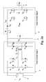
- FIGS. 2 a and 2 bshow details of an example power conditioning unit of the type shown in FIG. 1 ; like elements are indicated by like reference numerals.
- a Q 1 -Q 4 , D 1 -D 4 and the transformerform a dc-to-dc conversion stage, here a voltage amplifier.
- a centre-tapped transformer with two back-to-back diodesmay be used as the bridge circuit.
- Q 9 , D 5 , D 6 and L outperform current shaping.
- this functionmay be located in a connection between the bridge circuit and the dc link capacitor: D 6 acts as a free-wheeling diode and D 5 prevents current form flowing back into the dc-link.
- transistor Q 9When transistor Q 9 is switched on, a current builds up through L out .
- Q 9When Q 9 is switched off, this current cannot return to zero immediately so D 6 provides an alternative path for current to flow from the negative supply rail (D 5 prevents a current flowing back into the dc-link via the body diode in Q 9 : when Q 9 is switched off).
- Transistors Q 5 -Q 8constitutes an “unfolding” stage. Thus these transistors Q 5 -Q 8 form a full-bridge that switches at line frequency using an analogue circuit synchronised with the grid voltage. Transistors Q 5 and Q 8 are on during the positive half cycle of the grid voltage and Q 6 and Q 7 are on during the negative half cycle of the grid voltage.
- the power conditioning unitcomprises a generic dc-ac-dc that provides voltage amplification of the source to above the grid voltage, and isolation, and a current source inverter (CSI) connected to the mains.
- the current injectionis regulated using current shaping (current-control) in the inductor of the CSI via the intermediate buck-type stage. (This is described further in our GB2415841B, incorporated by reference).
- Control (block) A of FIG. 1may be connected to the control connections (e.g. gates or bases) of transistors in power converter stage A to control the transfer of power from the dc energy source.
- the input of this stageis connected to the dc energy source and the output of this stage is connected to the dc link capacitor. This capacitor stores energy from the dc energy source for delivery to the mains supply.
- Control (block) Amay be configured to draw such that the unit draws substantially constant power from the dc energy source regardless of the dc link voltage V dc on C dc .
- Control (block) Bmay be connected to the control connections of transistors in the power converter stage B to control the transfer of power to the mains supply.
- the input of this stageis connected to the dc link capacitor and the output of this stage is connected to the mains supply.
- Control Bmay be configured to inject a substantially sinusoidal current into the mains supply regardless of the dc link voltage V dc on C dc .
- the capacitor C dcacts as an energy buffer from the input to the output. Energy is supplied into the capacitor via the power stage A at the same time that energy is extracted from the capacitor via the power stage B.
- the systemprovides a control method that balances the average energy transfer and allows a voltage fluctuation, resulting from the injection of ac power into the mains, superimposed onto the average dc voltage of the capacitor C dc .
- the frequency of the oscillationcan be either 100 Hz or 120 Hz depending on the line voltage frequency (50 Hz or 60 Hz respectively).
- control block Acontrols the power stage A
- control block Bpower stage B
- An example implementation of control blocks A and Bis shown in FIG. 2 b . In this example these blocks operate independently but share a common microcontroller for simplicity.
- control block Asenses the dc input voltage (and/or current) and provides a PWM waveform to control the transistors of power stage A to control the power transferred across this power stage.
- Control block Bsenses the output current (and voltage) and controls the transistors of power stage B to control the power transferred to the mains.
- Many different control strategiesare possible. For example details of one preferred strategy reference may be made to our earlier filed WO2007/080429 (which senses the (ripple) voltage on the dc link)—but the embodiments of the invention we describe later do not rely on use of any particular control strategy.
- the microcontroller of FIG. 2 bwill generally implement an algorithm for some form of maximum power point tracking.
- this or a similar microcontrollermay be further configured to control whether one or both of the dc-to-dc power converter stages are operational, and to implement “soft” switching off of one of these stages when required.
- the microcontroller and/or associated hardwaremay also be configured to interleave the power transistor switching, preferably to reduce ripple as previously mentioned.
- FIG. 3 ashows a further example of a power conditioning unit 600 .
- a photovoltaic module 602provides a dc power source for dc-to-dc power conversion stage 604 , in this example each comprising an LLC resonant converter.
- power conversion stage 604comprises a dc-to-ac (switching) converter stage 606 to convert dc from module 602 to ac for a transformer 608 .
- the secondary side of transformer 608is coupled to a rectifying circuit 610 , which in turn provides a dc output to a series-coupled output inductor 612 .
- Output inductor 612is coupled to a dc link 614 of the power conditioning unit, to which is also coupled a dc link capacitor 616 .
- a dc-to-ac converter 618has a dc input from a dc link and provides an ac output 620 , for example to an ac grid mains supply.
- a microcontroller 622provides switching control signals to dc-to-ac converter 606 , to rectifying circuit 610 (for synchronous rectifiers), and to dc-to-ac converter 618 in the output ‘unfolding’ stage. As illustrated microcontroller 622 also senses the output voltage/current to the grid, the input voltage/current from the PV module 602 , and, in embodiments, the dc link voltage. (The skilled person will be aware of many ways in which such sensing may be performed). In some embodiments the microcontroller 622 implements a control strategy as previously described. As illustrated, the microcontroller 622 is coupled to an RF transceiver 624 such as a ZigBeeTM transceiver, which is provided with an antenna 626 for monitoring and control of the power conditioning unit 600 .
- RF transceiver 624such as a ZigBeeTM transceiver
- FIG. 3 bthis shows details of a portion of an example implementation of the arrangement of FIG. 3 a .
- This example arrangementemploys a modification of the circuit of FIG. 2 a and like elements to those of FIG. 2 a are indicated by like reference numerals; likewise like elements to those of FIG. 3 a are indicated by like reference numerals.
- an LLC converteris employed (by contrast with FIG. 2 a ), using a pair of resonant capacitors C 1 , C 3 .
- FIGS. 1 to 3are particularly useful for microinverters, for example having a maximum rate of power of less than 1000 Watts and or connected to a small number of PV modules, for example just one or two such modules.
- the panel voltagescan be as low as 20 volts and hence the conversion currents can be in excess of 30 amps RMS.
- transformer constructionswhich may be employed in the circuits of FIGS. 1 to 3 .
- FIG. 4 ashows a transformer construction 100 in accordance with an embodiment of the present invention.
- the transformer construction 100comprises three transformer cores 102 which are conjoined and are therefore configured to share magnetic flux paths.
- Each core 102comprises a post 104 provided between two sidewall portions 106 which combine to form an associated sidewall having a combined effective cross-sectional area which is 20% less than that of the post 104 .
- the posts 104each have a cross-sectional area of 100 mm 2 and the associated sidewall has an effective cross-sectional area of 80 mm 2 .
- the posts 104 and sidewalls 106are mounted on a common substrate (i.e. back wall) 108 and are arranged such that adjacent posts 104 share a common sidewall 106 .
- each core 102are provided such that a middle post 104 has two sidewalls 106 which are shared respectively by the posts 104 on either side of the middle post 104 .
- Each shared sidewall 106also has a cross-sectional area which is greater than a cross-sectional area of a sidewall 106 which is not shared.
- each post 104has an oval cross-sectional area as this further helps to minimise the volume of the transformer whilst allowing for optimum efficiency.
- the transformer construction 100may be employed in a power conditioning unit similar to that described above but wherein three separate DC sources are provided (e.g. constituted by three photovoltaic substrings). In which case, three separate drive circuits may be employed to operate the three cores 102 60 degrees out of phase from each other on a primary side of the transformer. Three outputs from the secondary side of the transformer may be connected in parallel before feeding into a dc link capacitor as described previously.
- the fact that the cores 102are operated in a particular sequence (i.e. phasing) allows the cores 102 to share magnetic flux paths without creating interference. Accordingly, the transformer core 102 volumes can be minimised without adversely affecting performance. In fact, in particular embodiments of the invention it is possible to minimise the size and optimise the efficiency of the transformer since the volume of the transformer core is directly proportional to the core losses.
- FIG. 4 bshows a variant of the transformer construction 100 and so like parts will be indicated using like reference numerals.
- FIG. 4 bshows a single transformer core 110 which may be magnetically coupled (e.g. connected) to two similar cores 110 to form the same structure as shown in FIG. 4 a although this time it is formed from three discrete cores 110 .
- the transformer core 110comprises a post 104 provided between two sidewall portions 106 .
- When two or more cores 110 are magnetically coupled together their respective sidewall portions 106will combine to form an associated sidewall having a combined effective cross-sectional area which is 20% less than that of the post 104 .
- the post 104 and two sidewalls 106are mounted on an individual substrate (i.e. back wall) 112 .
- each sidewall 106is of the same thickness such that when two cores 110 are coupled together the effective thickness of the shared sidewall is doubled.
- FIG. 4 cA further embodiment of the present invention is shown in FIG. 4 c .
- This construction 120effectively forms half of the transformer construction 100 of FIG. 4 a and so like reference numerals will be employed for like parts.
- the transformer construction 120therefore comprises a first post 104 and a first half of a second post 121 mounted on a first substrate 122 .
- Two sidewalls 106are provided around the first post 104 such that one of these forms a sidewall 106 that is shared with the first half of the second post 121 .
- the shared sidewall 106is twice the thickness of the sidewall 106 that is not shared.
- first and second halveswill be configured such that they can be coupled together to form essentially the same structure as illustrated in FIG. 4 a.
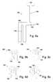
- FIG. 5 ashows a secondary bobbin structure 130 comprising an oval hollow (secondary) support 132 —configured for receipt of a post 104 of one of the transformer cores described above—mounted in the centre of a rectangular planar secondary substrate 134 which has a central hole therethrough.
- a free end of the support 132comprises an outwardly extending radial flange 136 .
- a secondary winding 142 of cylindrical wireis wound around the outer surface of the support 132 and the two free ends 144 of the winding 142 are passed through the two longitudinal channels 140 .
- these ends 144will be connected to a secondary circuit to drive the transformer such as provided in the power conditioning units discussed above.
- a primary bobbin structure 150which comprises a an oval hollow (primary) support 152 mounted in the centre of a rectangular planar primary substrate 154 which has a central hole 156 therethrough.
- Two sidewalls 158are provided on the primary substrate 154 on either side of the support 152 .
- the primary support 152is placed around the secondary support 132 until the free ends of the primary support 152 and sidewalls 158 abut the secondary substrate 134 .
- the flange 136will abut the primary substrate 154 and the inside of the primary support 152 to thereby maintain a desired spacing between the primary and second bobbin structures.
- a primary winding 160is wound around the primary support 152 .
- the primary winding 160is likely to be provided on the primary support 152 before the primary bobbin 150 is placed over the secondary bobbin 130 .
- the two-piece transformer bobbin structure 130 , 150 shown in FIGS. 5 a to 5 dcan provide improved manufacturability and efficiency performance in a transformer, particularly when combined with a transformer core construction of FIGS. 4 a to 4 c . More specifically, the bobbin structure can achieve tight tolerances on leakage inductance by ensuring a fixed physical separation between the primary and secondary windings 160 , 142 .
- FIG. 6shows the transformer construction of FIG. 4 c combined with the bobbin structure of FIG. 5 d according to an embodiment of the present invention.
- three out of four of the transformer core constructions 120 required in this embodimentare shown. More specifically, two constructions 120 are required to form a two-piece structure similar to that of FIG. 4 a and the same structure again is required to double the length of each of the posts 104 and to form a complete and enclosed transformer structure.
- the transformer bobbin structure 130 , 150 of FIG. 5 dis provided around each of the three (doubled) posts 104 (although for clarity, the primary bobbin structure 150 is not shown around the last post 104 ).
- the combination of the transformer construction and the bobbin structureprovides a compact and efficient transformer which can be employed in a power conditioning unit as described above.
- FIG. 7is similar to FIG. 6 but this time shows the transformer construction of FIG. 4 a combined with the bobbin structure of FIG. 5 d according to an embodiment of the present invention. Accordingly, only two of the transformer constructions 100 are required along with three of the transformer bobbin structures 130 , 150 , which are positioned over each post 104 .
- FIGS. 8 a through 8 eshow a transformer winding 180 in accordance with an embodiment of the present invention.
- the transformer winding 180may form the primary winding 160 described above.
- the transformer winding 180is stamped from a planar copper sheet and comprises a longitudinal spine 182 having a first turn 184 emanating from a first portion 186 of the spine 182 in a first transverse direction and a second turn 188 emanating from a second portion 190 of the spine 182 in a second transverse direction which is opposite to the first transverse direction.
- Each turn 184 , 188comprises a slit 194 along the centre of its length which helps to improve efficiency minimizing eddy current loss.
- the first turn 184is wound in a first direction (i.e. in a clockwise direction around a bobbin or core) and the second turn 188 is wound in an opposite (i.e. anti-clockwise) second direction.
- the winding 180has a simple 2 turn structure which is quick and easy to manufacture and assemble.
- the various aspects of the present inventioncan provide a transformer construction or parts therefore with improved manufacturability and efficiency.
- a multiple piece manufacturing approachcan be employed, that can be automated, such that all components of the core, windings and bobbins can be manufactured off-line and integrated together in a simple (few step) manufacturing process. Consequently, manufacturing errors can be minimised and reliability can be increased.
- the transformerWhen employed in a power conditioning unit, the transformer is a key component in relation to overall efficiency and so each of the features and techniques described above which help minimise the losses associated with the transformer will greatly improve the overall efficiency of the power conditioning unit.
Landscapes
- Engineering & Computer Science (AREA)
- Power Engineering (AREA)
- Manufacturing & Machinery (AREA)
- Dc-Dc Converters (AREA)
Abstract
Description
- providing a planar metal sheet;
- cutting said sheet to form a longitudinal spine having a first turn emanating from a first portion of the spine in a first transverse direction and a second turn emanating from a second portion of the spine in a second transverse direction, the second transverse direction being opposite to the first transverse direction; and
- winding the first turn in a first direction and the second turn in an opposite second direction.
- a primary bobbin mounted on a primary substrate;
- a secondary bobbin mounted on a secondary substrate;
- wherein the secondary bobbin is hollow and is configured for receipt of at least a portion of a transformer core therein and the primary bobbin is hollow and is configured for receipt of the secondary bobbin therein; and
- wherein at least one of the primary or secondary bobbins has a free end comprising a flange which is configured to maintain a pre-determined spacing between the primary and secondary bobbins.
- a plurality of single phase transformers; and
- a plurality of drive circuits arranged to operate the plurality of transformers out of phase from each other;
- wherein the transformers are configured to share magnetic flux paths.
- providing a plurality of single phase transformers configured to share magnetic flux paths, the transformers being arranged to be operated by a plurality of associated drive circuits; and
- operating the plurality of transformers out of phase from each other.
- 1) A high efficiency integrated magnetic structure that shares magnetic flux paths for volume optimisation;
- 2) Lower volume structure compared to single discrete transformers;
- 3) Stamped 2 turn primary winding with a simple (one forward, one back) fold forming sequence to achieve low dc resistance and low ac winding structure;
- 4) A 2 piece bobbin structure optimised for tight leakage inductance tolerance for improved resonant operation performance.
Claims (17)
Priority Applications (2)
| Application Number | Priority Date | Filing Date | Title |
|---|---|---|---|
| US13/771,024US8917156B2 (en) | 2011-11-03 | 2013-02-19 | Transformer construction |
| US14/531,120US9728324B2 (en) | 2011-11-03 | 2014-11-03 | Transformer construction |
Applications Claiming Priority (2)
| Application Number | Priority Date | Filing Date | Title |
|---|---|---|---|
| GB1118996.6 | 2011-11-03 | ||
| GB1118996.6AGB2496163B (en) | 2011-11-03 | 2011-11-03 | Transformer construction |
Related Child Applications (1)
| Application Number | Title | Priority Date | Filing Date |
|---|---|---|---|
| US13/771,024ContinuationUS8917156B2 (en) | 2011-11-03 | 2013-02-19 | Transformer construction |
Publications (2)
| Publication Number | Publication Date |
|---|---|
| US20120081204A1 US20120081204A1 (en) | 2012-04-05 |
| US8410889B2true US8410889B2 (en) | 2013-04-02 |
Family
ID=45375750
Family Applications (3)
| Application Number | Title | Priority Date | Filing Date |
|---|---|---|---|
| US13/297,253ActiveUS8410889B2 (en) | 2011-11-03 | 2011-11-15 | Transformer construction |
| US13/771,024ActiveUS8917156B2 (en) | 2011-11-03 | 2013-02-19 | Transformer construction |
| US14/531,120ActiveUS9728324B2 (en) | 2011-11-03 | 2014-11-03 | Transformer construction |
Family Applications After (2)
| Application Number | Title | Priority Date | Filing Date |
|---|---|---|---|
| US13/771,024ActiveUS8917156B2 (en) | 2011-11-03 | 2013-02-19 | Transformer construction |
| US14/531,120ActiveUS9728324B2 (en) | 2011-11-03 | 2014-11-03 | Transformer construction |
Country Status (2)
| Country | Link |
|---|---|
| US (3) | US8410889B2 (en) |
| GB (1) | GB2496163B (en) |
Cited By (61)
| Publication number | Priority date | Publication date | Assignee | Title |
|---|---|---|---|---|
| US20130229834A1 (en)* | 2011-11-03 | 2013-09-05 | Enecsys Limited | Transformer Construction |
| US8934269B2 (en) | 2011-03-22 | 2015-01-13 | Enecsys Limited | Solar photovoltaic power conditioning units |
| US20150263634A1 (en)* | 2014-03-14 | 2015-09-17 | Futurewei Technologies, Inc. | Hybrid Power Converter and Method |
| US20160012955A1 (en)* | 2014-07-08 | 2016-01-14 | Alliance Magnetics (H.K.) Co. Ltd. | Stacked inductor |
| US9270191B2 (en) | 2006-01-13 | 2016-02-23 | Solarcity Corporation | Power condition units with MPPT |
| US9318974B2 (en) | 2014-03-26 | 2016-04-19 | Solaredge Technologies Ltd. | Multi-level inverter with flying capacitor topology |
| US9520803B2 (en) | 2011-11-01 | 2016-12-13 | Solarcity Corporation | Photovoltaic power conditioning units |
| US9537445B2 (en) | 2008-12-04 | 2017-01-03 | Solaredge Technologies Ltd. | Testing of a photovoltaic panel |
| US9831824B2 (en) | 2007-12-05 | 2017-11-28 | SolareEdge Technologies Ltd. | Current sensing on a MOSFET |
| US9853490B2 (en) | 2006-12-06 | 2017-12-26 | Solaredge Technologies Ltd. | Distributed power system using direct current power sources |
| US9853565B2 (en) | 2012-01-30 | 2017-12-26 | Solaredge Technologies Ltd. | Maximized power in a photovoltaic distributed power system |
| US9876430B2 (en) | 2008-03-24 | 2018-01-23 | Solaredge Technologies Ltd. | Zero voltage switching |
| US9935458B2 (en) | 2010-12-09 | 2018-04-03 | Solaredge Technologies Ltd. | Disconnection of a string carrying direct current power |
| US9948233B2 (en) | 2006-12-06 | 2018-04-17 | Solaredge Technologies Ltd. | Distributed power harvesting systems using DC power sources |
| US9960731B2 (en) | 2006-12-06 | 2018-05-01 | Solaredge Technologies Ltd. | Pairing of components in a direct current distributed power generation system |
| US9966766B2 (en) | 2006-12-06 | 2018-05-08 | Solaredge Technologies Ltd. | Battery power delivery module |
| US10007288B2 (en) | 2012-03-05 | 2018-06-26 | Solaredge Technologies Ltd. | Direct current link circuit |
| US10097007B2 (en) | 2006-12-06 | 2018-10-09 | Solaredge Technologies Ltd. | Method for distributed power harvesting using DC power sources |
| US10116217B2 (en) | 2007-08-06 | 2018-10-30 | Solaredge Technologies Ltd. | Digital average input current control in power converter |
| US10230310B2 (en) | 2016-04-05 | 2019-03-12 | Solaredge Technologies Ltd | Safety switch for photovoltaic systems |
| US10381977B2 (en) | 2012-01-30 | 2019-08-13 | Solaredge Technologies Ltd | Photovoltaic panel circuitry |
| US10447150B2 (en) | 2006-12-06 | 2019-10-15 | Solaredge Technologies Ltd. | Distributed power harvesting systems using DC power sources |
| US10468878B2 (en) | 2008-05-05 | 2019-11-05 | Solaredge Technologies Ltd. | Direct current power combiner |
| US10476395B2 (en)* | 2017-11-30 | 2019-11-12 | Futurewei Technologies, Inc. | Voltage converting system and method of using the same |
| US10608553B2 (en) | 2012-01-30 | 2020-03-31 | Solaredge Technologies Ltd. | Maximizing power in a photovoltaic distributed power system |
| US10637393B2 (en) | 2006-12-06 | 2020-04-28 | Solaredge Technologies Ltd. | Distributed power harvesting systems using DC power sources |
| US10651647B2 (en) | 2013-03-15 | 2020-05-12 | Solaredge Technologies Ltd. | Bypass mechanism |
| US10666125B2 (en) | 2011-01-12 | 2020-05-26 | Solaredge Technologies Ltd. | Serially connected inverters |
| US10673229B2 (en) | 2010-11-09 | 2020-06-02 | Solaredge Technologies Ltd. | Arc detection and prevention in a power generation system |
| US10673222B2 (en) | 2010-11-09 | 2020-06-02 | Solaredge Technologies Ltd. | Arc detection and prevention in a power generation system |
| US10778025B2 (en) | 2013-03-14 | 2020-09-15 | Solaredge Technologies Ltd. | Method and apparatus for storing and depleting energy |
| US10931228B2 (en) | 2010-11-09 | 2021-02-23 | Solaredge Technologies Ftd. | Arc detection and prevention in a power generation system |
| US10969412B2 (en) | 2009-05-26 | 2021-04-06 | Solaredge Technologies Ltd. | Theft detection and prevention in a power generation system |
| US11018623B2 (en) | 2016-04-05 | 2021-05-25 | Solaredge Technologies Ltd. | Safety switch for photovoltaic systems |
| US11031861B2 (en) | 2006-12-06 | 2021-06-08 | Solaredge Technologies Ltd. | System and method for protection during inverter shutdown in distributed power installations |
| US11177768B2 (en) | 2012-06-04 | 2021-11-16 | Solaredge Technologies Ltd. | Integrated photovoltaic panel circuitry |
| US11177663B2 (en) | 2016-04-05 | 2021-11-16 | Solaredge Technologies Ltd. | Chain of power devices |
| US11264947B2 (en) | 2007-12-05 | 2022-03-01 | Solaredge Technologies Ltd. | Testing of a photovoltaic panel |
| US11296650B2 (en) | 2006-12-06 | 2022-04-05 | Solaredge Technologies Ltd. | System and method for protection during inverter shutdown in distributed power installations |
| US11309832B2 (en) | 2006-12-06 | 2022-04-19 | Solaredge Technologies Ltd. | Distributed power harvesting systems using DC power sources |
| US11309714B2 (en) | 2016-11-02 | 2022-04-19 | Tesla, Inc. | Micro-batteries for energy generation systems |
| US11539352B2 (en)* | 2013-11-14 | 2022-12-27 | Eagle Harbor Technologies, Inc. | Transformer resonant converter |
| US11545912B2 (en) | 2013-03-14 | 2023-01-03 | Solaredge Technologies Ltd. | High frequency multi-level inverter |
| US11598652B2 (en) | 2006-12-06 | 2023-03-07 | Solaredge Technologies Ltd. | Monitoring of distributed power harvesting systems using DC power sources |
| US11631573B2 (en) | 2014-02-28 | 2023-04-18 | Eagle Harbor Technologies, Inc. | High voltage resistive output stage circuit |
| US11646176B2 (en) | 2019-01-08 | 2023-05-09 | Eagle Harbor Technologies, Inc. | Efficient nanosecond pulser with source and sink capability for plasma control applications |
| US11687112B2 (en) | 2006-12-06 | 2023-06-27 | Solaredge Technologies Ltd. | Distributed power harvesting systems using DC power sources |
| US11728768B2 (en) | 2006-12-06 | 2023-08-15 | Solaredge Technologies Ltd. | Pairing of components in a direct current distributed power generation system |
| US11735910B2 (en) | 2006-12-06 | 2023-08-22 | Solaredge Technologies Ltd. | Distributed power system using direct current power sources |
| US11855231B2 (en) | 2006-12-06 | 2023-12-26 | Solaredge Technologies Ltd. | Distributed power harvesting systems using DC power sources |
| US11875971B2 (en) | 2018-07-27 | 2024-01-16 | Eagle Harbor Technologies, Inc. | Efficient energy recovery in a nanosecond pulser circuit |
| US11881814B2 (en) | 2005-12-05 | 2024-01-23 | Solaredge Technologies Ltd. | Testing of a photovoltaic panel |
| US11888387B2 (en) | 2006-12-06 | 2024-01-30 | Solaredge Technologies Ltd. | Safety mechanisms, wake up and shutdown methods in distributed power installations |
| US11979037B2 (en) | 2012-01-11 | 2024-05-07 | Solaredge Technologies Ltd. | Photovoltaic module |
| US12057807B2 (en) | 2016-04-05 | 2024-08-06 | Solaredge Technologies Ltd. | Chain of power devices |
| US12107417B2 (en) | 2006-12-06 | 2024-10-01 | Solaredge Technologies Ltd. | Distributed power harvesting systems using DC power sources |
| US12230477B2 (en) | 2018-07-27 | 2025-02-18 | Eagle Harbor Technologies, Inc. | Nanosecond pulser ADC system |
| US12348228B2 (en) | 2022-06-29 | 2025-07-01 | EHT Ventures LLC | Bipolar high voltage pulser |
| US12354832B2 (en) | 2022-09-29 | 2025-07-08 | Eagle Harbor Technologies, Inc. | High voltage plasma control |
| US12418177B2 (en) | 2009-10-24 | 2025-09-16 | Solaredge Technologies Ltd. | Distributed power system using direct current power sources |
| US12437967B2 (en) | 2020-07-09 | 2025-10-07 | Eagle Harbor Technologies, Inc. | Ion current droop compensation |
Families Citing this family (24)
| Publication number | Priority date | Publication date | Assignee | Title |
|---|---|---|---|---|
| US11569659B2 (en) | 2006-12-06 | 2023-01-31 | Solaredge Technologies Ltd. | Distributed power harvesting systems using DC power sources |
| WO2009073867A1 (en) | 2007-12-05 | 2009-06-11 | Solaredge, Ltd. | Parallel connected inverters |
| CN105244905B (en) | 2007-12-05 | 2019-05-21 | 太阳能安吉有限公司 | Release mechanism in distributed power device is waken up and method for closing |
| US9291696B2 (en) | 2007-12-05 | 2016-03-22 | Solaredge Technologies Ltd. | Photovoltaic system power tracking method |
| US8570005B2 (en) | 2011-09-12 | 2013-10-29 | Solaredge Technologies Ltd. | Direct current link circuit |
| US9053845B2 (en) | 2012-06-12 | 2015-06-09 | General Electric Company | Transformer with planar primary winding |
| US8995156B2 (en)* | 2012-12-11 | 2015-03-31 | Eaton Corporation | DC/DC converter with resonant converter stage and buck stage and method of controlling the same |
| WO2014095486A1 (en)* | 2012-12-19 | 2014-06-26 | Höganäs Ab (Publ) | An inductor and inductor core |
| CN103762846A (en)* | 2014-01-27 | 2014-04-30 | 陶顺祝 | Magnetic integrated resonant converter |
| US9473036B2 (en)* | 2014-06-05 | 2016-10-18 | Lite-On Electronics (Guangzhou) Limited | Direct current voltage conversion device |
| US9876437B2 (en)* | 2014-09-26 | 2018-01-23 | Lenovo Enterprise Solutions (Singapore) Pte. Ltd. | Interleaved transformer/inductor |
| US10486257B2 (en)* | 2014-11-07 | 2019-11-26 | Illinois Tool Works Inc. | Welding type power supply with transformer |
| CN104377010A (en)* | 2014-12-12 | 2015-02-25 | 东莞市吉之晟电子科技有限公司 | Transformer |
| US9559609B2 (en) | 2015-04-23 | 2017-01-31 | Chicony Power Technology Co., Ltd. | Integrated power-converting module |
| US10951123B2 (en) | 2015-04-23 | 2021-03-16 | Chicony Power Technology Co.. Ltd. | Power conversion system |
| TWI556273B (en)* | 2015-10-14 | 2016-11-01 | Yujing Technology Co Ltd | Resonant High Current Density Transformer |
| US12068674B2 (en)* | 2016-01-25 | 2024-08-20 | Delta Electronics (Shanghai) Co., Ltd | Integrated inductor and a power conversion module including the integrated inductor |
| CN106998142B (en)* | 2016-01-25 | 2019-08-30 | 台达电子企业管理(上海)有限公司 | Controlled resonant converter, the inductance of multi-channel parallel integrate magnetic element and transformer integrates magnetic element |
| CN105761905B (en)* | 2016-01-30 | 2018-01-09 | 明纬(广州)电子有限公司 | Resonant mode high current density transformer |
| TWI581280B (en)* | 2016-08-24 | 2017-05-01 | Yujing Technology Co Ltd | Improved Structure of Resonant High Current Density Transformer |
| CN107170567B (en)* | 2017-04-18 | 2023-06-09 | 重庆祥龙电气股份有限公司 | Synchronous isolation transformer |
| US10833591B2 (en) | 2017-07-24 | 2020-11-10 | Abb Power Electronics Inc. | Single-stage DC-DC power converter |
| CN110706900A (en)* | 2019-10-15 | 2020-01-17 | 恒天摩尔科技(山东)有限公司 | Multi-window type iron core structure, multi-window type transformer and inductor |
| US20230143466A1 (en)* | 2021-11-09 | 2023-05-11 | Cyntec Co., Ltd. | Magnetic component and magnetic body thereof |
Citations (28)
| Publication number | Priority date | Publication date | Assignee | Title |
|---|---|---|---|---|
| GB1118996A (en) | 1966-02-16 | 1968-07-03 | Int Harvester Co | Arrangement for mounting a loader on a vehicle |
| US3392326A (en)* | 1966-09-28 | 1968-07-09 | Gen Electric | Coil winding buffer conductors having impedance means |
| US4183079A (en) | 1977-07-05 | 1980-01-08 | Sony Corporaton | DC-AC inverter |
| GB1597508A (en) | 1976-12-23 | 1981-09-09 | Licentia Gmbh | E-cores |
| US4488136A (en)* | 1981-05-18 | 1984-12-11 | Westinghouse Electric Corp. | Combination transformer with common core portions |
| US4626983A (en) | 1983-10-06 | 1986-12-02 | Nishimu Electronics Industries Co., Ltd. | Power conversion device for solar cell |
| US5027059A (en)* | 1989-08-24 | 1991-06-25 | Schlumberger Industries, Inc. | Differential current shunt |
| EP0577334A2 (en) | 1992-07-02 | 1994-01-05 | AT&T Corp. | Partial gap magnetic core apparatus |
| US5576941A (en) | 1994-08-10 | 1996-11-19 | York Technologies, Inc. | Modular power supply system |
| US5726615A (en)* | 1994-03-24 | 1998-03-10 | Bloom; Gordon E. | Integrated-magnetic apparatus |
| US5812045A (en) | 1995-12-15 | 1998-09-22 | Toko, Inc. | Inverter transformer |
| US6021052A (en) | 1997-09-22 | 2000-02-01 | Statpower Technologies Partnership | DC/AC power converter |
| GB2376807A (en) | 2001-06-13 | 2002-12-24 | Lite On Electronics Inc | Inductor with air gap having multiple separations |
| US6501362B1 (en)* | 2000-11-28 | 2002-12-31 | Umec Usa, Inc. | Ferrite core |
| EP1400988A2 (en) | 2002-09-17 | 2004-03-24 | Matsushita Electric Industrial Co., Ltd. | Step-up transformer for magnetron driving |
| JP2004111754A (en) | 2002-09-19 | 2004-04-08 | Sumitomo Special Metals Co Ltd | Inductor |
| US20040189432A1 (en) | 2001-10-12 | 2004-09-30 | Liang Yan | Integrated magnetics for a dc-dc converter with flexible output inductor |
| GB2415841A (en) | 2004-11-08 | 2006-01-04 | Enecsys Ltd | Power conditioning unit for connecting dc source to a mains utility supply |
| WO2007080429A2 (en) | 2006-01-13 | 2007-07-19 | Enecsys Limited | Power conditioning unit |
| US20090302986A1 (en)* | 2008-06-10 | 2009-12-10 | Bedea Tiberiu A | Minimal-length windings for reduction of copper power losses in magnetic elements |
| US7649434B2 (en)* | 2006-01-31 | 2010-01-19 | Virginia Tech Intellectual Properties, Inc. | Multiphase voltage regulator having coupled inductors with reduced winding resistance |
| DE202010004898U1 (en) | 2010-04-12 | 2010-08-12 | Sunrise Power Transformers Gmbh | The energy saving rotary transformer with several galvanically isolated undervoltage windings |
| WO2010119324A2 (en) | 2009-04-16 | 2010-10-21 | Toyota Jidosha Kabushiki Kaisha | Onboard multiphase converter |
| US7994891B2 (en)* | 2004-08-12 | 2011-08-09 | Pulse Engineering, Inc. | Stacked inductive device assemblies and methods |
| US8072305B2 (en)* | 2007-03-30 | 2011-12-06 | Tdk Corporation | DC/DC converter |
| EP2395517A1 (en) | 2010-06-09 | 2011-12-14 | STS, Spezial-Transformatoren-Stockach GmbH & Co. | Inductive component with magnetic core |
| USD657311S1 (en)* | 2010-07-28 | 2012-04-10 | Lien Chang Electronics Enterprise Co., Ltd. | Cores in juxtaposition |
| US8310332B2 (en)* | 2008-10-08 | 2012-11-13 | Cooper Technologies Company | High current amorphous powder core inductor |
Family Cites Families (13)
| Publication number | Priority date | Publication date | Assignee | Title |
|---|---|---|---|---|
| US3328738A (en)* | 1965-04-23 | 1967-06-27 | Westinghouse Electric Corp | Five-legged magnetic core structures and windings which produce flux in quadrature |
| US4234865A (en)* | 1979-07-09 | 1980-11-18 | Katsumi Shigehara | Transformer framing structure |
| US4800356A (en)* | 1987-12-01 | 1989-01-24 | Eaton Corporation | Shunt transformer |
| US4988968A (en)* | 1988-11-01 | 1991-01-29 | Musashino Tuko Co., Ltd. | Double insulated transformer and bobbin case thereof |
| AU4617696A (en)* | 1995-02-15 | 1996-09-04 | Electronic Craftsmen Limited | Transformer and method of assembly |
| JP2000182850A (en)* | 1998-12-11 | 2000-06-30 | Alps Electric Co Ltd | Thin-film transformer |
| US6344786B1 (en)* | 2000-10-06 | 2002-02-05 | Artesyn Technologies, Inc. | Telescoping bobbin |
| US6727793B2 (en)* | 2001-08-21 | 2004-04-27 | Astec International Limited | Low-power transformer for printed circuit boards |
| US20040210289A1 (en)* | 2002-03-04 | 2004-10-21 | Xingwu Wang | Novel nanomagnetic particles |
| JP4960110B2 (en)* | 2006-04-19 | 2012-06-27 | スミダコーポレーション株式会社 | Transformer device and drive circuit thereof |
| US20100157632A1 (en) | 2008-12-20 | 2010-06-24 | Azuray Technologies, Inc. | Energy Conversion Systems With Power Control |
| FR2964264A1 (en) | 2010-08-24 | 2012-03-02 | Solairemed | PHOTOVOLTAIC INSTALLATION AND METHOD FOR DELIVERING ELECTRIC POWER EQUAL TO A PREDETERMINED VALUE. |
| GB2496163B (en) | 2011-11-03 | 2015-11-11 | Enecsys Ltd | Transformer construction |
- 2011
- 2011-11-03GBGB1118996.6Apatent/GB2496163B/enactiveActive
- 2011-11-15USUS13/297,253patent/US8410889B2/enactiveActive
- 2013
- 2013-02-19USUS13/771,024patent/US8917156B2/enactiveActive
- 2014
- 2014-11-03USUS14/531,120patent/US9728324B2/enactiveActive
Patent Citations (28)
| Publication number | Priority date | Publication date | Assignee | Title |
|---|---|---|---|---|
| GB1118996A (en) | 1966-02-16 | 1968-07-03 | Int Harvester Co | Arrangement for mounting a loader on a vehicle |
| US3392326A (en)* | 1966-09-28 | 1968-07-09 | Gen Electric | Coil winding buffer conductors having impedance means |
| GB1597508A (en) | 1976-12-23 | 1981-09-09 | Licentia Gmbh | E-cores |
| US4183079A (en) | 1977-07-05 | 1980-01-08 | Sony Corporaton | DC-AC inverter |
| US4488136A (en)* | 1981-05-18 | 1984-12-11 | Westinghouse Electric Corp. | Combination transformer with common core portions |
| US4626983A (en) | 1983-10-06 | 1986-12-02 | Nishimu Electronics Industries Co., Ltd. | Power conversion device for solar cell |
| US5027059A (en)* | 1989-08-24 | 1991-06-25 | Schlumberger Industries, Inc. | Differential current shunt |
| EP0577334A2 (en) | 1992-07-02 | 1994-01-05 | AT&T Corp. | Partial gap magnetic core apparatus |
| US5726615A (en)* | 1994-03-24 | 1998-03-10 | Bloom; Gordon E. | Integrated-magnetic apparatus |
| US5576941A (en) | 1994-08-10 | 1996-11-19 | York Technologies, Inc. | Modular power supply system |
| US5812045A (en) | 1995-12-15 | 1998-09-22 | Toko, Inc. | Inverter transformer |
| US6021052A (en) | 1997-09-22 | 2000-02-01 | Statpower Technologies Partnership | DC/AC power converter |
| US6501362B1 (en)* | 2000-11-28 | 2002-12-31 | Umec Usa, Inc. | Ferrite core |
| GB2376807A (en) | 2001-06-13 | 2002-12-24 | Lite On Electronics Inc | Inductor with air gap having multiple separations |
| US20040189432A1 (en) | 2001-10-12 | 2004-09-30 | Liang Yan | Integrated magnetics for a dc-dc converter with flexible output inductor |
| EP1400988A2 (en) | 2002-09-17 | 2004-03-24 | Matsushita Electric Industrial Co., Ltd. | Step-up transformer for magnetron driving |
| JP2004111754A (en) | 2002-09-19 | 2004-04-08 | Sumitomo Special Metals Co Ltd | Inductor |
| US7994891B2 (en)* | 2004-08-12 | 2011-08-09 | Pulse Engineering, Inc. | Stacked inductive device assemblies and methods |
| GB2415841A (en) | 2004-11-08 | 2006-01-04 | Enecsys Ltd | Power conditioning unit for connecting dc source to a mains utility supply |
| WO2007080429A2 (en) | 2006-01-13 | 2007-07-19 | Enecsys Limited | Power conditioning unit |
| US7649434B2 (en)* | 2006-01-31 | 2010-01-19 | Virginia Tech Intellectual Properties, Inc. | Multiphase voltage regulator having coupled inductors with reduced winding resistance |
| US8072305B2 (en)* | 2007-03-30 | 2011-12-06 | Tdk Corporation | DC/DC converter |
| US20090302986A1 (en)* | 2008-06-10 | 2009-12-10 | Bedea Tiberiu A | Minimal-length windings for reduction of copper power losses in magnetic elements |
| US8310332B2 (en)* | 2008-10-08 | 2012-11-13 | Cooper Technologies Company | High current amorphous powder core inductor |
| WO2010119324A2 (en) | 2009-04-16 | 2010-10-21 | Toyota Jidosha Kabushiki Kaisha | Onboard multiphase converter |
| DE202010004898U1 (en) | 2010-04-12 | 2010-08-12 | Sunrise Power Transformers Gmbh | The energy saving rotary transformer with several galvanically isolated undervoltage windings |
| EP2395517A1 (en) | 2010-06-09 | 2011-12-14 | STS, Spezial-Transformatoren-Stockach GmbH & Co. | Inductive component with magnetic core |
| USD657311S1 (en)* | 2010-07-28 | 2012-04-10 | Lien Chang Electronics Enterprise Co., Ltd. | Cores in juxtaposition |
Non-Patent Citations (1)
| Title |
|---|
| Portions of prosecution history of GB 1118996, Mar. 1, 2012 (mailing date), Enecsys Limited. |
Cited By (135)
| Publication number | Priority date | Publication date | Assignee | Title |
|---|---|---|---|---|
| US11881814B2 (en) | 2005-12-05 | 2024-01-23 | Solaredge Technologies Ltd. | Testing of a photovoltaic panel |
| US9270191B2 (en) | 2006-01-13 | 2016-02-23 | Solarcity Corporation | Power condition units with MPPT |
| US10193467B2 (en) | 2006-01-13 | 2019-01-29 | Tesla, Inc. | Power conditioning units |
| US9812980B2 (en) | 2006-01-13 | 2017-11-07 | Solarcity Corporation | Power conditioning units |
| US11888387B2 (en) | 2006-12-06 | 2024-01-30 | Solaredge Technologies Ltd. | Safety mechanisms, wake up and shutdown methods in distributed power installations |
| US11296650B2 (en) | 2006-12-06 | 2022-04-05 | Solaredge Technologies Ltd. | System and method for protection during inverter shutdown in distributed power installations |
| US12224706B2 (en) | 2006-12-06 | 2025-02-11 | Solaredge Technologies Ltd. | Pairing of components in a direct current distributed power generation system |
| US11043820B2 (en) | 2006-12-06 | 2021-06-22 | Solaredge Technologies Ltd. | Battery power delivery module |
| US12107417B2 (en) | 2006-12-06 | 2024-10-01 | Solaredge Technologies Ltd. | Distributed power harvesting systems using DC power sources |
| US12068599B2 (en) | 2006-12-06 | 2024-08-20 | Solaredge Technologies Ltd. | System and method for protection during inverter shutdown in distributed power installations |
| US11031861B2 (en) | 2006-12-06 | 2021-06-08 | Solaredge Technologies Ltd. | System and method for protection during inverter shutdown in distributed power installations |
| US12046940B2 (en) | 2006-12-06 | 2024-07-23 | Solaredge Technologies Ltd. | Battery power control |
| US12027970B2 (en) | 2006-12-06 | 2024-07-02 | Solaredge Technologies Ltd. | Safety mechanisms, wake up and shutdown methods in distributed power installations |
| US12281919B2 (en) | 2006-12-06 | 2025-04-22 | Solaredge Technologies Ltd. | Monitoring of distributed power harvesting systems using DC power sources |
| US11183922B2 (en) | 2006-12-06 | 2021-11-23 | Solaredge Technologies Ltd. | Distributed power harvesting systems using DC power sources |
| US9853490B2 (en) | 2006-12-06 | 2017-12-26 | Solaredge Technologies Ltd. | Distributed power system using direct current power sources |
| US12027849B2 (en) | 2006-12-06 | 2024-07-02 | Solaredge Technologies Ltd. | Distributed power system using direct current power sources |
| US10230245B2 (en) | 2006-12-06 | 2019-03-12 | Solaredge Technologies Ltd | Battery power delivery module |
| US11962243B2 (en) | 2006-12-06 | 2024-04-16 | Solaredge Technologies Ltd. | Method for distributed power harvesting using DC power sources |
| US9948233B2 (en) | 2006-12-06 | 2018-04-17 | Solaredge Technologies Ltd. | Distributed power harvesting systems using DC power sources |
| US9960731B2 (en) | 2006-12-06 | 2018-05-01 | Solaredge Technologies Ltd. | Pairing of components in a direct current distributed power generation system |
| US9966766B2 (en) | 2006-12-06 | 2018-05-08 | Solaredge Technologies Ltd. | Battery power delivery module |
| US11309832B2 (en) | 2006-12-06 | 2022-04-19 | Solaredge Technologies Ltd. | Distributed power harvesting systems using DC power sources |
| US11961922B2 (en) | 2006-12-06 | 2024-04-16 | Solaredge Technologies Ltd. | Distributed power harvesting systems using DC power sources |
| US11476799B2 (en) | 2006-12-06 | 2022-10-18 | Solaredge Technologies Ltd. | Distributed power harvesting systems using DC power sources |
| US10097007B2 (en) | 2006-12-06 | 2018-10-09 | Solaredge Technologies Ltd. | Method for distributed power harvesting using DC power sources |
| US10673253B2 (en) | 2006-12-06 | 2020-06-02 | Solaredge Technologies Ltd. | Battery power delivery module |
| US11063440B2 (en) | 2006-12-06 | 2021-07-13 | Solaredge Technologies Ltd. | Method for distributed power harvesting using DC power sources |
| US12276997B2 (en) | 2006-12-06 | 2025-04-15 | Solaredge Technologies Ltd. | Distributed power harvesting systems using DC power sources |
| US12316274B2 (en) | 2006-12-06 | 2025-05-27 | Solaredge Technologies Ltd. | Pairing of components in a direct current distributed power generation system |
| US10637393B2 (en) | 2006-12-06 | 2020-04-28 | Solaredge Technologies Ltd. | Distributed power harvesting systems using DC power sources |
| US11855231B2 (en) | 2006-12-06 | 2023-12-26 | Solaredge Technologies Ltd. | Distributed power harvesting systems using DC power sources |
| US11735910B2 (en) | 2006-12-06 | 2023-08-22 | Solaredge Technologies Ltd. | Distributed power system using direct current power sources |
| US10447150B2 (en) | 2006-12-06 | 2019-10-15 | Solaredge Technologies Ltd. | Distributed power harvesting systems using DC power sources |
| US11728768B2 (en) | 2006-12-06 | 2023-08-15 | Solaredge Technologies Ltd. | Pairing of components in a direct current distributed power generation system |
| US11598652B2 (en) | 2006-12-06 | 2023-03-07 | Solaredge Technologies Ltd. | Monitoring of distributed power harvesting systems using DC power sources |
| US11682918B2 (en) | 2006-12-06 | 2023-06-20 | Solaredge Technologies Ltd. | Battery power delivery module |
| US12388492B2 (en) | 2006-12-06 | 2025-08-12 | Solaredge Technologies Ltd. | Safety mechanisms, wake up and shutdown methods in distributed power installations |
| US11687112B2 (en) | 2006-12-06 | 2023-06-27 | Solaredge Technologies Ltd. | Distributed power harvesting systems using DC power sources |
| US10116217B2 (en) | 2007-08-06 | 2018-10-30 | Solaredge Technologies Ltd. | Digital average input current control in power converter |
| US10516336B2 (en) | 2007-08-06 | 2019-12-24 | Solaredge Technologies Ltd. | Digital average input current control in power converter |
| US11594968B2 (en) | 2007-08-06 | 2023-02-28 | Solaredge Technologies Ltd. | Digital average input current control in power converter |
| US9979280B2 (en) | 2007-12-05 | 2018-05-22 | Solaredge Technologies Ltd. | Parallel connected inverters |
| US11693080B2 (en) | 2007-12-05 | 2023-07-04 | Solaredge Technologies Ltd. | Parallel connected inverters |
| US11894806B2 (en) | 2007-12-05 | 2024-02-06 | Solaredge Technologies Ltd. | Testing of a photovoltaic panel |
| US10644589B2 (en) | 2007-12-05 | 2020-05-05 | Solaredge Technologies Ltd. | Parallel connected inverters |
| US11264947B2 (en) | 2007-12-05 | 2022-03-01 | Solaredge Technologies Ltd. | Testing of a photovoltaic panel |
| US11183969B2 (en) | 2007-12-05 | 2021-11-23 | Solaredge Technologies Ltd. | Testing of a photovoltaic panel |
| US11183923B2 (en) | 2007-12-05 | 2021-11-23 | Solaredge Technologies Ltd. | Parallel connected inverters |
| US9831824B2 (en) | 2007-12-05 | 2017-11-28 | SolareEdge Technologies Ltd. | Current sensing on a MOSFET |
| US12055647B2 (en) | 2007-12-05 | 2024-08-06 | Solaredge Technologies Ltd. | Parallel connected inverters |
| US9876430B2 (en) | 2008-03-24 | 2018-01-23 | Solaredge Technologies Ltd. | Zero voltage switching |
| US10468878B2 (en) | 2008-05-05 | 2019-11-05 | Solaredge Technologies Ltd. | Direct current power combiner |
| US11424616B2 (en) | 2008-05-05 | 2022-08-23 | Solaredge Technologies Ltd. | Direct current power combiner |
| US12218498B2 (en) | 2008-05-05 | 2025-02-04 | Solaredge Technologies Ltd. | Direct current power combiner |
| US10461687B2 (en) | 2008-12-04 | 2019-10-29 | Solaredge Technologies Ltd. | Testing of a photovoltaic panel |
| US9537445B2 (en) | 2008-12-04 | 2017-01-03 | Solaredge Technologies Ltd. | Testing of a photovoltaic panel |
| US11867729B2 (en) | 2009-05-26 | 2024-01-09 | Solaredge Technologies Ltd. | Theft detection and prevention in a power generation system |
| US12306215B2 (en) | 2009-05-26 | 2025-05-20 | Solaredge Technologies Ltd. | Theft detection and prevention in a power generation system |
| US10969412B2 (en) | 2009-05-26 | 2021-04-06 | Solaredge Technologies Ltd. | Theft detection and prevention in a power generation system |
| US12418177B2 (en) | 2009-10-24 | 2025-09-16 | Solaredge Technologies Ltd. | Distributed power system using direct current power sources |
| US12407158B2 (en) | 2010-11-09 | 2025-09-02 | Solaredge Technologies Ltd. | Arc detection and prevention in a power generation system |
| US12003215B2 (en) | 2010-11-09 | 2024-06-04 | Solaredge Technologies Ltd. | Arc detection and prevention in a power generation system |
| US10673229B2 (en) | 2010-11-09 | 2020-06-02 | Solaredge Technologies Ltd. | Arc detection and prevention in a power generation system |
| US11070051B2 (en) | 2010-11-09 | 2021-07-20 | Solaredge Technologies Ltd. | Arc detection and prevention in a power generation system |
| US10931228B2 (en) | 2010-11-09 | 2021-02-23 | Solaredge Technologies Ftd. | Arc detection and prevention in a power generation system |
| US11489330B2 (en) | 2010-11-09 | 2022-11-01 | Solaredge Technologies Ltd. | Arc detection and prevention in a power generation system |
| US10673222B2 (en) | 2010-11-09 | 2020-06-02 | Solaredge Technologies Ltd. | Arc detection and prevention in a power generation system |
| US11349432B2 (en) | 2010-11-09 | 2022-05-31 | Solaredge Technologies Ltd. | Arc detection and prevention in a power generation system |
| US11271394B2 (en) | 2010-12-09 | 2022-03-08 | Solaredge Technologies Ltd. | Disconnection of a string carrying direct current power |
| US12295184B2 (en) | 2010-12-09 | 2025-05-06 | Solaredge Technologies Ltd. | Disconnection of a string carrying direct current power |
| US9935458B2 (en) | 2010-12-09 | 2018-04-03 | Solaredge Technologies Ltd. | Disconnection of a string carrying direct current power |
| US11996488B2 (en) | 2010-12-09 | 2024-05-28 | Solaredge Technologies Ltd. | Disconnection of a string carrying direct current power |
| US10141745B2 (en) | 2011-01-11 | 2018-11-27 | Tesla, Inc. | Photovoltaic power conditioning units |
| US11205946B2 (en) | 2011-01-12 | 2021-12-21 | Solaredge Technologies Ltd. | Serially connected inverters |
| US10666125B2 (en) | 2011-01-12 | 2020-05-26 | Solaredge Technologies Ltd. | Serially connected inverters |
| US12218505B2 (en) | 2011-01-12 | 2025-02-04 | Solaredge Technologies Ltd. | Serially connected inverters |
| US9584036B2 (en) | 2011-03-22 | 2017-02-28 | Solarcity Corporation | Solar photovoltaic power conditioning units |
| US10008858B2 (en) | 2011-03-22 | 2018-06-26 | Tesla, Inc. | Solar photovoltaic power conditioning units |
| US8934269B2 (en) | 2011-03-22 | 2015-01-13 | Enecsys Limited | Solar photovoltaic power conditioning units |
| US10424936B2 (en) | 2011-03-22 | 2019-09-24 | Tesla, Inc. | Solar photovoltaic power conditioning units |
| US9520803B2 (en) | 2011-11-01 | 2016-12-13 | Solarcity Corporation | Photovoltaic power conditioning units |
| US9728324B2 (en) | 2011-11-03 | 2017-08-08 | Solarcity Corporation | Transformer construction |
| US20130229834A1 (en)* | 2011-11-03 | 2013-09-05 | Enecsys Limited | Transformer Construction |
| US8917156B2 (en)* | 2011-11-03 | 2014-12-23 | Enecsys Limited | Transformer construction |
| US11979037B2 (en) | 2012-01-11 | 2024-05-07 | Solaredge Technologies Ltd. | Photovoltaic module |
| US10992238B2 (en) | 2012-01-30 | 2021-04-27 | Solaredge Technologies Ltd. | Maximizing power in a photovoltaic distributed power system |
| US9853565B2 (en) | 2012-01-30 | 2017-12-26 | Solaredge Technologies Ltd. | Maximized power in a photovoltaic distributed power system |
| US11620885B2 (en) | 2012-01-30 | 2023-04-04 | Solaredge Technologies Ltd. | Photovoltaic panel circuitry |
| US11183968B2 (en) | 2012-01-30 | 2021-11-23 | Solaredge Technologies Ltd. | Photovoltaic panel circuitry |
| US10608553B2 (en) | 2012-01-30 | 2020-03-31 | Solaredge Technologies Ltd. | Maximizing power in a photovoltaic distributed power system |
| US10381977B2 (en) | 2012-01-30 | 2019-08-13 | Solaredge Technologies Ltd | Photovoltaic panel circuitry |
| US12094306B2 (en) | 2012-01-30 | 2024-09-17 | Solaredge Technologies Ltd. | Photovoltaic panel circuitry |
| US11929620B2 (en) | 2012-01-30 | 2024-03-12 | Solaredge Technologies Ltd. | Maximizing power in a photovoltaic distributed power system |
| US12191668B2 (en) | 2012-01-30 | 2025-01-07 | Solaredge Technologies Ltd. | Maximizing power in a photovoltaic distributed power system |
| US10007288B2 (en) | 2012-03-05 | 2018-06-26 | Solaredge Technologies Ltd. | Direct current link circuit |
| US11177768B2 (en) | 2012-06-04 | 2021-11-16 | Solaredge Technologies Ltd. | Integrated photovoltaic panel circuitry |
| US12218628B2 (en) | 2012-06-04 | 2025-02-04 | Solaredge Technologies Ltd. | Integrated photovoltaic panel circuitry |
| US12119758B2 (en) | 2013-03-14 | 2024-10-15 | Solaredge Technologies Ltd. | High frequency multi-level inverter |
| US12255457B2 (en) | 2013-03-14 | 2025-03-18 | Solaredge Technologies Ltd. | Method and apparatus for storing and depleting energy |
| US10778025B2 (en) | 2013-03-14 | 2020-09-15 | Solaredge Technologies Ltd. | Method and apparatus for storing and depleting energy |
| US11742777B2 (en) | 2013-03-14 | 2023-08-29 | Solaredge Technologies Ltd. | High frequency multi-level inverter |
| US12003107B2 (en) | 2013-03-14 | 2024-06-04 | Solaredge Technologies Ltd. | Method and apparatus for storing and depleting energy |
| US11545912B2 (en) | 2013-03-14 | 2023-01-03 | Solaredge Technologies Ltd. | High frequency multi-level inverter |
| US11424617B2 (en) | 2013-03-15 | 2022-08-23 | Solaredge Technologies Ltd. | Bypass mechanism |
| US12132125B2 (en) | 2013-03-15 | 2024-10-29 | Solaredge Technologies Ltd. | Bypass mechanism |
| US10651647B2 (en) | 2013-03-15 | 2020-05-12 | Solaredge Technologies Ltd. | Bypass mechanism |
| US11539352B2 (en)* | 2013-11-14 | 2022-12-27 | Eagle Harbor Technologies, Inc. | Transformer resonant converter |
| US11631573B2 (en) | 2014-02-28 | 2023-04-18 | Eagle Harbor Technologies, Inc. | High voltage resistive output stage circuit |
| US9548668B2 (en)* | 2014-03-14 | 2017-01-17 | Futurewei Technologies, Inc. | Hybrid power converter and method |
| US20150263634A1 (en)* | 2014-03-14 | 2015-09-17 | Futurewei Technologies, Inc. | Hybrid Power Converter and Method |
| US10886831B2 (en) | 2014-03-26 | 2021-01-05 | Solaredge Technologies Ltd. | Multi-level inverter |
| US10886832B2 (en) | 2014-03-26 | 2021-01-05 | Solaredge Technologies Ltd. | Multi-level inverter |
| US11296590B2 (en) | 2014-03-26 | 2022-04-05 | Solaredge Technologies Ltd. | Multi-level inverter |
| US12136890B2 (en) | 2014-03-26 | 2024-11-05 | Solaredge Technologies Ltd. | Multi-level inverter |
| US11855552B2 (en) | 2014-03-26 | 2023-12-26 | Solaredge Technologies Ltd. | Multi-level inverter |
| US11632058B2 (en) | 2014-03-26 | 2023-04-18 | Solaredge Technologies Ltd. | Multi-level inverter |
| US9318974B2 (en) | 2014-03-26 | 2016-04-19 | Solaredge Technologies Ltd. | Multi-level inverter with flying capacitor topology |
| US9305696B2 (en)* | 2014-07-08 | 2016-04-05 | Alliance Magnetics (H.K.) Co. Ltd. | Stacked inductor |
| US20160012955A1 (en)* | 2014-07-08 | 2016-01-14 | Alliance Magnetics (H.K.) Co. Ltd. | Stacked inductor |
| US11201476B2 (en) | 2016-04-05 | 2021-12-14 | Solaredge Technologies Ltd. | Photovoltaic power device and wiring |
| US11018623B2 (en) | 2016-04-05 | 2021-05-25 | Solaredge Technologies Ltd. | Safety switch for photovoltaic systems |
| US12348182B2 (en) | 2016-04-05 | 2025-07-01 | Solaredge Technologies Ltd. | Safety switch for photovoltaic systems |
| US11870250B2 (en) | 2016-04-05 | 2024-01-09 | Solaredge Technologies Ltd. | Chain of power devices |
| US11177663B2 (en) | 2016-04-05 | 2021-11-16 | Solaredge Technologies Ltd. | Chain of power devices |
| US10230310B2 (en) | 2016-04-05 | 2019-03-12 | Solaredge Technologies Ltd | Safety switch for photovoltaic systems |
| US12057807B2 (en) | 2016-04-05 | 2024-08-06 | Solaredge Technologies Ltd. | Chain of power devices |
| US11309714B2 (en) | 2016-11-02 | 2022-04-19 | Tesla, Inc. | Micro-batteries for energy generation systems |
| US10476395B2 (en)* | 2017-11-30 | 2019-11-12 | Futurewei Technologies, Inc. | Voltage converting system and method of using the same |
| US11875971B2 (en) | 2018-07-27 | 2024-01-16 | Eagle Harbor Technologies, Inc. | Efficient energy recovery in a nanosecond pulser circuit |
| US12230477B2 (en) | 2018-07-27 | 2025-02-18 | Eagle Harbor Technologies, Inc. | Nanosecond pulser ADC system |
| US11646176B2 (en) | 2019-01-08 | 2023-05-09 | Eagle Harbor Technologies, Inc. | Efficient nanosecond pulser with source and sink capability for plasma control applications |
| US12437967B2 (en) | 2020-07-09 | 2025-10-07 | Eagle Harbor Technologies, Inc. | Ion current droop compensation |
| US12348228B2 (en) | 2022-06-29 | 2025-07-01 | EHT Ventures LLC | Bipolar high voltage pulser |
| US12354832B2 (en) | 2022-09-29 | 2025-07-08 | Eagle Harbor Technologies, Inc. | High voltage plasma control |
Also Published As
| Publication number | Publication date |
|---|---|
| US20120081204A1 (en) | 2012-04-05 |
| GB2496163A (en) | 2013-05-08 |
| US9728324B2 (en) | 2017-08-08 |
| GB2496163B (en) | 2015-11-11 |
| US8917156B2 (en) | 2014-12-23 |
| US20150243431A1 (en) | 2015-08-27 |
| US20130229834A1 (en) | 2013-09-05 |
| GB201118996D0 (en) | 2011-12-14 |
Similar Documents
| Publication | Publication Date | Title |
|---|---|---|
| US9728324B2 (en) | Transformer construction | |
| US10424936B2 (en) | Solar photovoltaic power conditioning units | |
| CN110168896B (en) | DC-to-DC converter and control method | |
| CN102812628B (en) | Resonant circuit and resonant dc/dc converter | |
| US8842450B2 (en) | Power converter using multiple phase-shifting quasi-resonant converters | |
| US9614453B2 (en) | Parallel hybrid converter apparatus and method | |
| EP2965329B1 (en) | Integrated magnetics transformer assembly | |
| EP2779393B1 (en) | Bridgeless interleaved power factor correction circuit using a PFC inductor with quad-winding on a single core | |
| EP2571154B1 (en) | PV inverter with input parallel output series connected flyback converters feeding a fullbridge grid converter | |
| US20130336013A1 (en) | DC-to-DC Converter and Method for Operating a DC-to-DC Converter | |
| KR20170002447A (en) | A resonant dc-dc power converter assembly | |
| Vinnikov et al. | Comparison of performance of phase-shift and asymmetrical pulsewidth modulation techniques for the novel galvanically isolated buck–boost DC–DC converter for photovoltaic applications | |
| WO2019076874A1 (en) | A dc-dc converter assembly | |
| Li et al. | An efficiency-oriented two-stage structure employing partial power regulation | |
| Sree et al. | Hybrid modulated extended secondary universal current-fed ZVS converter for wide voltage range: Analysis, design, and experimental results | |
| US11764692B2 (en) | DC to DC boost converter | |
| GB2491494A (en) | Photovoltaic power conditioning unit having plural dc-dc converters | |
| Li et al. | A high step-up current fed multi-resonant converter with coupled inductor | |
| Saravanan et al. | A Boost Converter for High Voltage Applications using Three State Switching Cell |
Legal Events
| Date | Code | Title | Description |
|---|---|---|---|
| AS | Assignment | Owner name:ENECSYS LIMITED, UNITED KINGDOM Free format text:ASSIGNMENT OF ASSIGNORS INTEREST;ASSIGNORS:GARRITY, PAUL;SILVA, ARTURO;SIGNING DATES FROM 20120305 TO 20130205;REEL/FRAME:029759/0086 | |
| STCF | Information on status: patent grant | Free format text:PATENTED CASE | |
| AS | Assignment | Owner name:SOLARCITY CORPORATION, CALIFORNIA Free format text:ASSIGNMENT OF ASSIGNORS INTEREST;ASSIGNOR:ENECSYS LIMITED;REEL/FRAME:036329/0598 Effective date:20150420 | |
| AS | Assignment | Owner name:SOLARCITY CORPORATION, CALIFORNIA Free format text:CORRECTIVE ASSIGNMENT TO CORRECT THE CONVEYING PARTY FROM "ENECSYS LIMITED" TO "ENECSYS UK LIMITED" PREVIOUSLY RECORDED ON REEL 036329 FRAME 0598. ASSIGNOR(S) HEREBY CONFIRMS THE ASSIGNMENT;ASSIGNOR:ENECSYS UK LIMITED;REEL/FRAME:036805/0877 Effective date:20150420 Owner name:ENECSYS UK LIMITED, UNITED KINGDOM Free format text:CHANGE OF NAME;ASSIGNOR:ENECSYS LIMITED;REEL/FRAME:036741/0578 Effective date:20140604 | |
| FEPP | Fee payment procedure | Free format text:PAT HOLDER NO LONGER CLAIMS SMALL ENTITY STATUS, ENTITY STATUS SET TO UNDISCOUNTED (ORIGINAL EVENT CODE: STOL); ENTITY STATUS OF PATENT OWNER: LARGE ENTITY | |
| FPAY | Fee payment | Year of fee payment:4 | |
| MAFP | Maintenance fee payment | Free format text:PAYMENT OF MAINTENANCE FEE, 8TH YEAR, LARGE ENTITY (ORIGINAL EVENT CODE: M1552); ENTITY STATUS OF PATENT OWNER: LARGE ENTITY Year of fee payment:8 | |
| AS | Assignment | Owner name:TESLA, INC., CALIFORNIA Free format text:ASSIGNMENT OF ASSIGNORS INTEREST;ASSIGNOR:SOLARCITY CORPORATION;REEL/FRAME:056172/0062 Effective date:20210316 | |
| MAFP | Maintenance fee payment | Free format text:PAYMENT OF MAINTENANCE FEE, 12TH YEAR, LARGE ENTITY (ORIGINAL EVENT CODE: M1553); ENTITY STATUS OF PATENT OWNER: LARGE ENTITY Year of fee payment:12 |