US8409296B2 - Brow lift implant and method - Google Patents
Brow lift implant and methodDownload PDFInfo
- Publication number
- US8409296B2 US8409296B2US12/639,177US63917709AUS8409296B2US 8409296 B2US8409296 B2US 8409296B2US 63917709 AUS63917709 AUS 63917709AUS 8409296 B2US8409296 B2US 8409296B2
- Authority
- US
- United States
- Prior art keywords
- implant
- length
- implant according
- longitudinal axis
- foot portion
- Prior art date
- Legal status (The legal status is an assumption and is not a legal conclusion. Google has not performed a legal analysis and makes no representation as to the accuracy of the status listed.)
- Expired - Fee Related, expires
Links
Images


Classifications
- A—HUMAN NECESSITIES
- A61—MEDICAL OR VETERINARY SCIENCE; HYGIENE
- A61F—FILTERS IMPLANTABLE INTO BLOOD VESSELS; PROSTHESES; DEVICES PROVIDING PATENCY TO, OR PREVENTING COLLAPSING OF, TUBULAR STRUCTURES OF THE BODY, e.g. STENTS; ORTHOPAEDIC, NURSING OR CONTRACEPTIVE DEVICES; FOMENTATION; TREATMENT OR PROTECTION OF EYES OR EARS; BANDAGES, DRESSINGS OR ABSORBENT PADS; FIRST-AID KITS
- A61F2/00—Filters implantable into blood vessels; Prostheses, i.e. artificial substitutes or replacements for parts of the body; Appliances for connecting them with the body; Devices providing patency to, or preventing collapsing of, tubular structures of the body, e.g. stents
- A61F2/0059—Cosmetic or alloplastic implants
- A—HUMAN NECESSITIES
- A61—MEDICAL OR VETERINARY SCIENCE; HYGIENE
- A61B—DIAGNOSIS; SURGERY; IDENTIFICATION
- A61B17/00—Surgical instruments, devices or methods
- A61B2017/00004—(bio)absorbable, (bio)resorbable or resorptive
- A—HUMAN NECESSITIES
- A61—MEDICAL OR VETERINARY SCIENCE; HYGIENE
- A61F—FILTERS IMPLANTABLE INTO BLOOD VESSELS; PROSTHESES; DEVICES PROVIDING PATENCY TO, OR PREVENTING COLLAPSING OF, TUBULAR STRUCTURES OF THE BODY, e.g. STENTS; ORTHOPAEDIC, NURSING OR CONTRACEPTIVE DEVICES; FOMENTATION; TREATMENT OR PROTECTION OF EYES OR EARS; BANDAGES, DRESSINGS OR ABSORBENT PADS; FIRST-AID KITS
- A61F2210/00—Particular material properties of prostheses classified in groups A61F2/00 - A61F2/26 or A61F2/82 or A61F9/00 or A61F11/00 or subgroups thereof
- A61F2210/0004—Particular material properties of prostheses classified in groups A61F2/00 - A61F2/26 or A61F2/82 or A61F9/00 or A61F11/00 or subgroups thereof bioabsorbable
- A—HUMAN NECESSITIES
- A61—MEDICAL OR VETERINARY SCIENCE; HYGIENE
- A61F—FILTERS IMPLANTABLE INTO BLOOD VESSELS; PROSTHESES; DEVICES PROVIDING PATENCY TO, OR PREVENTING COLLAPSING OF, TUBULAR STRUCTURES OF THE BODY, e.g. STENTS; ORTHOPAEDIC, NURSING OR CONTRACEPTIVE DEVICES; FOMENTATION; TREATMENT OR PROTECTION OF EYES OR EARS; BANDAGES, DRESSINGS OR ABSORBENT PADS; FIRST-AID KITS
- A61F2250/00—Special features of prostheses classified in groups A61F2/00 - A61F2/26 or A61F2/82 or A61F9/00 or A61F11/00 or subgroups thereof
- A61F2250/0014—Special features of prostheses classified in groups A61F2/00 - A61F2/26 or A61F2/82 or A61F9/00 or A61F11/00 or subgroups thereof having different values of a given property or geometrical feature, e.g. mechanical property or material property, at different locations within the same prosthesis
- A61F2250/0018—Special features of prostheses classified in groups A61F2/00 - A61F2/26 or A61F2/82 or A61F9/00 or A61F11/00 or subgroups thereof having different values of a given property or geometrical feature, e.g. mechanical property or material property, at different locations within the same prosthesis differing in elasticity, stiffness or compressibility
Definitions
- the present inventionrelates generally to surgical implants, and more particularly to surgical implants and methods for re-positioning and/or lifting a patient's eye brow.
- Repositioning or lifting of the eyebrowis a surgical procedure typically performed to address tissue laxity or “sagging” that occurs as a result of trauma or injury, or more commonly as part of the typical aging process.
- the eyebrowIn a balanced, youthful female face, the eyebrow is lower medially (toward the center of the face), and higher laterally, with a variable arch in between.
- the entire browIn a male face, there is no distinct difference between medial and lateral aspects of the brow—the entire brow is positioned horizontally.
- Early signs of brow and periorbital aginginclude brow ptosis with a lowering of the medial and lateral hair-bearing brow and development of a vertical glabellar and horizontal forehead lines. These changes can result in alterations of facial expressions, exhibiting a tired, concerned, or even angry look. Often, there is a real or apparent excess of skin on the upper eyelid.
- the brow lift techniquesare typically characterized as coronal, endoscopic, or limited-incision foreheadplasty techniques.
- the open standard coronal brow liftwas for many years the only option for forehead and brow rejuvenation, and it remains today the gold standard against which other newer, less invasive techniques are measured.
- a relatively long incision(7-9 cm) is typically made along the same direction as, but posterior to the frontal hairline.
- the incisionmay be placed anterior to the frontal hairline if it is desired to shorten a long forehead.
- the forehead flapis then elevated, excess skin and tissue excised, and the wound subsequently closed.
- the limited-incision foreheadplasty techniqueis focused on the correction of the lateral portion of the brow.
- Two bilateral temporal scalp incisions and two upper blepharoplasty incisionsare made, through which the muscles and tissue are repositioned.
- incisionsare limited and endoscopic equipment is not needed, there is less visualization for dissection than with either the coronal incision or the endoscopic techniques, making familiarity with local anatomy important and requiring a skilled surgeon.
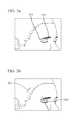
- brow lift proceduresIn addition to the fixation devices motioned above, devices such as barbed sutures, mesh and tined devices have also been known to be used in brow lift procedures. At least one surgeon is known to have utilized a planar, implantable polypropylene mesh in brow lift procedures.
- the mesh 100is approximately 3 cm in width, and is placed under the galeal plane above the periosteum, and extends from just above the brow and up the forehead as shown in FIGS. 1 and 1 a . Tissue ingrowth occurs, eventually causing the implanted mesh to serve as an artificial suspensory aponeurosis that provides stable fixation to maintain the elevated position of the eyebrow. Due to its placement under the galeal plane above the periosteum, this implant remains palpable under the forehead skin. Further, this implant and procedure does not allow a gradient brow elevation where the level of brow elevation increases from the medial toward the lateral side. Gradient brow elevation is advantageous in providing a desired, authentic result in large number of female patients.
- An implantfor repositioning a patient's eyebrow that includes a foot portion adapted to be positioned along at least a portion of the length of the patient's eyebrow, extending along a first longitudinal axis and having a length.
- the implantalso includes a vertical strip portion extending outwardly from the foot portion and adapted to extend upwardly across at least a portion of a patient's forehead.
- the vertical strip portionextends along a second longitudinal axis and has a length, and a width that is smaller than the length of the foot.
- the second longitudinal axisis offset from the center of the length of the foot portion, and the implant is substantially flat, having first and second opposing surfaces.
- the first and second longitudinal axesform an obtuse angle therebetween at the point of intersection, which preferably is greater than approximately 105 degrees, and may be approximately 105 to 125 degrees. More preferably, the angle therebetween is approximately 117 degrees.
- the implantmay be made of an entirely absorbable material or materials, and in one embodiment is made of an absorbable mesh.
- the implantfurther includes an absorbable film on the first and/or second surfaces, which may be a polydioxanone film.
- the polydioxanone filmmay have a thickness of approximately 20-200 ⁇ m, and in the alternative may have a thickness of approximately 50 ⁇ m on the vertical strip portion, and a thickness of approximately 150 ⁇ m on the foot portion.
- the implantfurther includes a plurality of holes therethrough.
- an implant for repositioning a patient's eyebrowincluding a substantially flat, strip of biocompatible material having a lateral side, a medial side, a proximal end and an angled distal end, wherein at least one mechanical property of the implant is different on the lateral side than on the medial side.
- the mechanical propertymay be stiffness.
- the implantmay include one or more different materials on the lateral side than on the medial side.
- the implantmay be made of absorbable material that has a first density on the lateral side, and a second, different density on the medial side.
- the absorbable materialmay be an absorbable mesh and/or may further include a plurality of holes therethrough on the medial side.
- an implant for repositioning a patient's eyebrowthat includes a substantially flat strip of biocompatible material having a proximal end, a distal end, and lateral and medial sides.
- the implantis non-symmetrical in that it is adapted, when the distal end is fixedly secured to a patient's tissue at a plurality of points along its length and when a pulling force is applied to the proximal end, to provide a gradient lift of the patient's tissue along the length of the distal end of the implant.
- the implantis geometrically non-symmetrical.
- the implantfurther includes a foot portion that includes the distal end, and a vertical strip portion extending outwardly from the foot portion. The longitudinal axis of the vertical strip portion is offset from the center of the length of the foot portion.
- an obtuse angleis formed at the point of intersection of the longitudinal axes of the foot portion and vertical strip portion. This obtuse angle may be between 105 and 125 degrees.
- the implantmay have non-symmetrical mechanical properties, and in one embodiment may have a stiffness that is different on the lateral side than on the medial side.
- the implantincludes one or more different materials on the lateral side than on the medial side.
- the implantmay further be made of an absorbable material that has a first density on the lateral side, and a second, different density on the medial side.
- the absorbable materialmay further be an absorbable mesh.
- the implantis made of an absorbable material having a plurality of holes therethrough on the medial side.
- FIGS. 1 and 1 aillustrate a known prior art brow lift implant and procedure.
- FIGS. 2 a - 2 cillustrate an exemplary implant according to the present invention.
- FIGS. 3 a - 3 dillustrate various steps in a method for implanting the implant of FIG. 2 a.
- FIGS. 4 a - 4 billustrate relative positioning of the implant of FIG. 2 a before and after tension is applied to lift the brow of a patient.
- FIGS. 5 and 6illustrate alternate embodiments of the present invention.
- FIGS. 2 a - 2 cillustrate an exemplary implant for brow lift procedures according to the present invention.
- the implant 200includes a distal end portion or “foot” portion 202 , and a vertical strip portion 204 .
- the distal end portionextends along a first longitudinal axis L 1
- the vertical strip portionextends along a second longitudinal axis L 2 .
- the first and second longitudinal axes L 1 , L 2intersect at an obtuse angle ⁇ .
- the longitudinal axis L 2is also offset from the centerline C-C (“offset” as used herein) that bisects the length l 1 of the foot portion, which in the illustrated embodiment is approximately 27.5 mm.
- the length l 2 and width w 2 of the vertical strip portion 204are approximately 82 mm and 12 mm respectively, and the width w 1 of the foot portion 202 is approximately 10 mm.
- the overall length l 3 and width w 3 of this embodiment of the implantis approximately 100 and 24.8 mm respectively.
- a “gradient lift” along the brow as the phrase is used hereinmeans that the amount of lifting of the brow is greater at the lateral brow than it is at the medial brow (portion closest to center of the forehead).
- a “one vector pull” as the phrase is used herein,means that the surgeon need only place tension on the implant from substantially a single point.
- the implant 200is fully absorbable and may be comprised of an absorbable mesh material such as Vicryl® mesh, which is manufactured by Ethicon, Inc. of Somerville, N.J.
- the implantis further laminated with a 50 ⁇ m polydioxanone (PDS) film. It is also preferable to further laminate the foot portion 202 with an additional 100 ⁇ m PDS film to enhance stiffness to allow better tension distribution when the strip is being pulled as will be described further below. Increased stiffness of the foot portion ensures better stress distribution across the entire span of the foot portion resulting in a smooth brow lift, and will also prevent buckling or distortion of the foot portion when the vertical strip portion is pulled by the surgeon.
- PDSpolydioxanone
- the implantmay have a plurality of holes 206 therethrough to facilitate tissue ingrowth.
- the holesare approximately 1.5 mm in diameter and on the vertical strip portion 204 are placed along multiple parallel lines such that distances d 1 and d 2 are approximately 2.5 mm.
- holesare placed through the foot portion such that distances d 3 and d 4 are approximately 5.5 and 3.5 mm respectively.
- FIGS. 3 a - 3 dwhere FIGS. 3 a and 3 d illustrate a patient before and after implantation surgery, placement of the implant of FIG. 2 a will now be described in detail.
- the implant and the lateral brow lift procedurewill be used in conjunction with the blepharoplasty where excess of the upper eyelid skin is removed to rejuvenate the eye.
- the implantis placed using two incisions, a first 300 along the upper eyelid as a part of blepharoplasty procedure and a second 302 superior to the frontal hairline in the temporal region as shown in FIG. 3 b .
- the first incision 300is a line above the eyelash line at the levels of the medial canthus, mid-pupil, and lateral canthus, respectively.
- the lower blade of forcepsis placed over the line, and the excess upper eyelid skin is “pinched” to absorb the excess.
- the elliptical area of excess upper eyelid skinis then marked.
- the lateral forehead skinis then pushed up with a finger to locate the single vector line V along which the lateral eyebrow will be raised.
- This single vector line Vpreferably falls along the lateral side of the temporal fusion line of the skull vertically across the lateral forehead as shown in FIG. 3 c .
- a 1-2 cm lineis drawn perpendicular to the vector line.
- the excess lower eyelid skinis then excised with the known blepharoplasty procedure, and dissection is performed approximately 2 cm upwardly from the first incision.
- the second incision 302is then made at the location described above, and dissection is taken down through the superficial temporal fascia to the level of the deep temporal fascia.
- the superficial temporal fasciais then separated from the deep temporal fascia, with the dissection between these fascial planes stopping at the orbicularis temporal ligament.
- the eyelid incision 300is again used to raise the superficial temporal fascia from its adhesion to the lateral orbital rim and release it from the bone.
- a periosteal elevatoris used to raise periosteum over the entire frontal bone allowing this space to communicate with the subperiosteal space previously created through the upper eyelid or first incision 300 .
- the implant 200is then introduced through the upper eyelid incision and passed under the periosteum, and a suitable instrument is used to pull the vertical strip portion up through the temporal scalp incision.
- the foot portion 202 of the implantis positioned under the eyebrow and is fixated with suture stitches to the suborbicularis fascia under the eyebrow.
- the holes 206 in the foot portionmay be used as suture points.
- the vertical strip portion 204is centered on a point just medial to the junction of the middle and lateral thirds of the eyebrow.
- the proximal end 310 of the vertical strip portionshould be positioned just lateral to the temporal fusion line of the skull, and under the periosteum lining of the elevated forehead flap.
- the upper portion 312 of the vertical strip portioncrosses the temporal fusion line of the skull to extend over deep temporal fascia as illustrated in FIG. 3 c .
- the surgeonthen pulls the implant 200 in the direction of the arrow of FIG. 3 c to raise the brow to a desired level.
- FIG. 4 billustrates the position of the implant after raising the brow to a suitable position.
- a gradient liftis achieved along the length of the brow from lateral 320 to medial 322 sides.
- the liftis concentrated at the lateral portion of the brow, and gradually decreases toward the medial portion of the brow.
- the angle ⁇is obtuse, and preferably between approximately 105 and 125 degrees, and more preferably approximately 117 degrees.
- the gradient liftis achieved by the non-symmetrical geometry of having the longitudinal axis L 2 of the vertical strip portion offset from the centerline C-C of the longitudinal axis L 1 of the foot portion as described above.
- the gradient liftcan also be achieved by other means, such as by utilizing one or more non-uniform or non-symmetrical mechanical properties across the implant.
- non-uniform mechanical properties, especially stiffnesscan be achieved by using mesh or other material with different woven patterns, different thicknesses (with one material or more than one material), different materials, preferential reinforcement, different porosities across the width of the device, or any suitable combination.
- an implantmay be constructed having additional reinforcement on the lateral side (i.e., side placed nearest the lateral side of the brow).
- FIG. 5One example illustrated in FIG. 5 is an implant 500 comprised of a substantially rectangular strip with an angled distal end 502 having an angle ⁇ of approximately 25 degrees.
- the implantis comprised of an absorbable Vicryl® mesh that is laminated with a 20 ⁇ m PDS film, and an additional 100 ⁇ m PDS film on the lateral portion 504 of the implant as opposed to the medial portion 506 .
- Non-uniform stiffnessmay also be achieved across a mesh implant that is laminated with a PDS film by providing additional embroidery on the implant at predetermined locations, such as on the lateral side of the device.
- the implantis “non-symmetric” in terms of mechanical properties.
- FIG. 6illustrates another embodiment according to the present invention comprised of a substantially uniform material or materials throughout, but having a plurality of apertures 508 placed through the medial portion 506 to achieve non-symmetrical mechanical properties from medial to lateral as described above.
Landscapes
- Health & Medical Sciences (AREA)
- Cardiology (AREA)
- Oral & Maxillofacial Surgery (AREA)
- Transplantation (AREA)
- Engineering & Computer Science (AREA)
- Biomedical Technology (AREA)
- Heart & Thoracic Surgery (AREA)
- Vascular Medicine (AREA)
- Life Sciences & Earth Sciences (AREA)
- Animal Behavior & Ethology (AREA)
- General Health & Medical Sciences (AREA)
- Public Health (AREA)
- Veterinary Medicine (AREA)
- Prostheses (AREA)
- Materials For Medical Uses (AREA)
- Infusion, Injection, And Reservoir Apparatuses (AREA)
Abstract
Description
Claims (11)
Priority Applications (5)
| Application Number | Priority Date | Filing Date | Title |
|---|---|---|---|
| US12/639,177US8409296B2 (en) | 2009-12-16 | 2009-12-16 | Brow lift implant and method |
| ES10796532.9TES2444617T3 (en) | 2009-12-16 | 2010-12-09 | Eyebrow lift implants |
| EP10796532.9AEP2512367B1 (en) | 2009-12-16 | 2010-12-09 | Brow lift implant |
| PCT/US2010/059681WO2011084344A2 (en) | 2009-12-16 | 2010-12-09 | Brow lift implant and method |
| BR112012014680ABR112012014680A2 (en) | 2009-12-16 | 2010-12-09 | brow lift implant and method |
Applications Claiming Priority (1)
| Application Number | Priority Date | Filing Date | Title |
|---|---|---|---|
| US12/639,177US8409296B2 (en) | 2009-12-16 | 2009-12-16 | Brow lift implant and method |
Publications (2)
| Publication Number | Publication Date |
|---|---|
| US20110144750A1 US20110144750A1 (en) | 2011-06-16 |
| US8409296B2true US8409296B2 (en) | 2013-04-02 |
Family
ID=43857857
Family Applications (1)
| Application Number | Title | Priority Date | Filing Date |
|---|---|---|---|
| US12/639,177Expired - Fee RelatedUS8409296B2 (en) | 2009-12-16 | 2009-12-16 | Brow lift implant and method |
Country Status (5)
| Country | Link |
|---|---|
| US (1) | US8409296B2 (en) |
| EP (1) | EP2512367B1 (en) |
| BR (1) | BR112012014680A2 (en) |
| ES (1) | ES2444617T3 (en) |
| WO (1) | WO2011084344A2 (en) |
Cited By (5)
| Publication number | Priority date | Publication date | Assignee | Title |
|---|---|---|---|---|
| US20110308529A1 (en)* | 2010-05-21 | 2011-12-22 | Gillis Edward M | Systems and methods for treatment of sleep apnea |
| US9381109B2 (en) | 2010-03-19 | 2016-07-05 | Revent Medical, Inc. | Systems and methods for treatment of sleep apnea |
| US9439801B2 (en) | 2012-06-29 | 2016-09-13 | Revent Medical, Inc. | Systems and methods for treatment of sleep apnea |
| US9510922B2 (en) | 2010-05-21 | 2016-12-06 | Revent Medical, Inc. | Systems and methods for treatment of sleep apnea |
| US9707122B2 (en) | 2010-07-26 | 2017-07-18 | Revent Medical, Inc. | Systems and methods for treatment of sleep apnea |
Families Citing this family (1)
| Publication number | Priority date | Publication date | Assignee | Title |
|---|---|---|---|---|
| US20140277453A1 (en) | 2013-03-14 | 2014-09-18 | Bethany R. Seidel | Ciliary implant, ciliary augmentation |
Citations (12)
| Publication number | Priority date | Publication date | Assignee | Title |
|---|---|---|---|---|
| US5217494A (en)* | 1989-01-12 | 1993-06-08 | Coggins Peter R | Tissue supporting prosthesis |
| US5611814A (en)* | 1994-11-16 | 1997-03-18 | Lorenc; Z. Paul | Resorbable surgical appliances and endoscopic soft tissue suspension procedure |
| US6015410A (en) | 1997-12-23 | 2000-01-18 | Bionx Implants Oy | Bioabsorbable surgical implants for endoscopic soft tissue suspension procedure |
| US20010044637A1 (en) | 2000-05-19 | 2001-11-22 | Daniel Jacobs | Multi-point tension distribution device, a brow and face lift variation, and a method of tissue approximation using the device |
| US6908473B2 (en) | 2000-04-14 | 2005-06-21 | Jeffry B. Skiba | Tissue anchoring devices, biological vessel suspending devices and systems and methods utilizing same |
| US20050240224A1 (en) | 2004-04-07 | 2005-10-27 | Wu Tze Liang W | Surgical thread |
| US20050283256A1 (en)* | 2004-02-09 | 2005-12-22 | Codman & Shurtleff, Inc. | Collagen device and method of preparing the same |
| US7056331B2 (en) | 2001-06-29 | 2006-06-06 | Quill Medical, Inc. | Suture method |
| US20080082113A1 (en) | 2006-10-03 | 2008-04-03 | Alure Medical, Inc. | Minimally invasive tissue support |
| US20080200993A1 (en)* | 2007-02-15 | 2008-08-21 | Jenifer Lee Henderson | Temporal Brow Lifting and Fixation Device |
| US20090082791A1 (en) | 2007-09-26 | 2009-03-26 | Ethicon, Inc. | Self-anchoring tissue lifting device, method of manufacturing same and method of facial reconstructive surgery using same |
| US20090198335A1 (en) | 2008-01-31 | 2009-08-06 | Barbosa Karen S | Infra-orbital implant |
- 2009
- 2009-12-16USUS12/639,177patent/US8409296B2/ennot_activeExpired - Fee Related
- 2010
- 2010-12-09EPEP10796532.9Apatent/EP2512367B1/enactiveActive
- 2010-12-09ESES10796532.9Tpatent/ES2444617T3/enactiveActive
- 2010-12-09WOPCT/US2010/059681patent/WO2011084344A2/enactiveApplication Filing
- 2010-12-09BRBR112012014680Apatent/BR112012014680A2/ennot_activeApplication Discontinuation
Patent Citations (15)
| Publication number | Priority date | Publication date | Assignee | Title |
|---|---|---|---|---|
| US5217494A (en)* | 1989-01-12 | 1993-06-08 | Coggins Peter R | Tissue supporting prosthesis |
| US5611814A (en)* | 1994-11-16 | 1997-03-18 | Lorenc; Z. Paul | Resorbable surgical appliances and endoscopic soft tissue suspension procedure |
| US6015410A (en) | 1997-12-23 | 2000-01-18 | Bionx Implants Oy | Bioabsorbable surgical implants for endoscopic soft tissue suspension procedure |
| US6908473B2 (en) | 2000-04-14 | 2005-06-21 | Jeffry B. Skiba | Tissue anchoring devices, biological vessel suspending devices and systems and methods utilizing same |
| US20010044637A1 (en) | 2000-05-19 | 2001-11-22 | Daniel Jacobs | Multi-point tension distribution device, a brow and face lift variation, and a method of tissue approximation using the device |
| US6485503B2 (en) | 2000-05-19 | 2002-11-26 | Coapt Systems, Inc. | Multi-point tissue tension distribution device, a brow and face lift variation, and a method of tissue approximation using the device |
| US20020022861A1 (en)* | 2000-05-19 | 2002-02-21 | Daniel Jacobs | Multi-point tissue tension distribution device, a combined orbital rim repair and suspension variation, and a method of tissue approximation using the device |
| US7056331B2 (en) | 2001-06-29 | 2006-06-06 | Quill Medical, Inc. | Suture method |
| US20050283256A1 (en)* | 2004-02-09 | 2005-12-22 | Codman & Shurtleff, Inc. | Collagen device and method of preparing the same |
| US20090030526A1 (en)* | 2004-02-09 | 2009-01-29 | Codman & Shurtleff, Inc. | Collagen device and method of preparing the same |
| US20050240224A1 (en) | 2004-04-07 | 2005-10-27 | Wu Tze Liang W | Surgical thread |
| US20080082113A1 (en) | 2006-10-03 | 2008-04-03 | Alure Medical, Inc. | Minimally invasive tissue support |
| US20080200993A1 (en)* | 2007-02-15 | 2008-08-21 | Jenifer Lee Henderson | Temporal Brow Lifting and Fixation Device |
| US20090082791A1 (en) | 2007-09-26 | 2009-03-26 | Ethicon, Inc. | Self-anchoring tissue lifting device, method of manufacturing same and method of facial reconstructive surgery using same |
| US20090198335A1 (en) | 2008-01-31 | 2009-08-06 | Barbosa Karen S | Infra-orbital implant |
Non-Patent Citations (3)
| Title |
|---|
| International Search Report mailed Jul. 29, 2011 for corresponding Patent Application No. PCT/US2010/059681. |
| Mutaf, M., "Mesh Lift: A New Procedure for Long-Lasting Results in Brow Lift Surgery", Plastic Reconstructive Surgery (2005), 116(5), 1490-1499. |
| Pascali , M. "An Original Application of the Endotine Ribbon Device for Brow Lift", American Society of Plastic Surgeons, (2009) 1652-1661. |
Cited By (5)
| Publication number | Priority date | Publication date | Assignee | Title |
|---|---|---|---|---|
| US9381109B2 (en) | 2010-03-19 | 2016-07-05 | Revent Medical, Inc. | Systems and methods for treatment of sleep apnea |
| US20110308529A1 (en)* | 2010-05-21 | 2011-12-22 | Gillis Edward M | Systems and methods for treatment of sleep apnea |
| US9510922B2 (en) | 2010-05-21 | 2016-12-06 | Revent Medical, Inc. | Systems and methods for treatment of sleep apnea |
| US9707122B2 (en) | 2010-07-26 | 2017-07-18 | Revent Medical, Inc. | Systems and methods for treatment of sleep apnea |
| US9439801B2 (en) | 2012-06-29 | 2016-09-13 | Revent Medical, Inc. | Systems and methods for treatment of sleep apnea |
Also Published As
| Publication number | Publication date |
|---|---|
| WO2011084344A2 (en) | 2011-07-14 |
| ES2444617T3 (en) | 2014-02-26 |
| WO2011084344A8 (en) | 2012-06-28 |
| EP2512367B1 (en) | 2013-11-13 |
| BR112012014680A2 (en) | 2016-04-05 |
| EP2512367A2 (en) | 2012-10-24 |
| US20110144750A1 (en) | 2011-06-16 |
| WO2011084344A3 (en) | 2011-09-22 |
Similar Documents
| Publication | Publication Date | Title |
|---|---|---|
| US8721666B2 (en) | Method of facial reconstructive surgery using a self-anchoring tissue lifting device | |
| JP5922130B2 (en) | Nasal column struts to support the tip of the nose | |
| Toriumi | New concepts in nasal tip contouring | |
| AU2005230815B2 (en) | Surgical thread | |
| US8257245B2 (en) | Adjustable sling as a support of internal organs or anatomical tissues | |
| US8409296B2 (en) | Brow lift implant and method | |
| US20080082129A1 (en) | Minimally-invasive mastoplasty procedure and apparatus | |
| US20080275502A1 (en) | Lifting instrument for removing skinfolds and plasty method of removing skinfolds using the same | |
| JP2010505543A (en) | Minimally invasive tissue support | |
| JP2011510687A (en) | System and method for soft tissue remodeling | |
| WO2013177238A1 (en) | Universal bioabsorable nasal implant kit | |
| WO2011091483A1 (en) | Surgical thread and surgical device for lifting and suspension of soft tissues. | |
| JP2008538964A (en) | Soft tissue support | |
| Fan | Frontalis suspension technique with a temporal-fasciae-complex sheet for repairing blepharoptosis | |
| US20190117362A1 (en) | Tissue products with variations in mechanical properties and methods of treatment | |
| RU2645118C1 (en) | System for surgical repair of frontal and apical units of pelvic floor in women | |
| CN216365412U (en) | Device for lifting skin tissue | |
| KR20100134941A (en) | Time difference face lift device | |
| KR101202253B1 (en) | Coupling face lifting device | |
| Meltzer | Complications of enucleation and evisceration: prevention and treatment | |
| Hamra | Periorbital rejuvenation in composite rhytidectomy | |
| CN216876628U (en) | A device for pulling and pulling skin tissue | |
| Leung et al. | Blepharoplasty–special focus on Asian blepharoplasty | |
| RU2575145C2 (en) | Columellar strut for nasal tip support | |
| Slonim et al. | Enucleation |
Legal Events
| Date | Code | Title | Description |
|---|---|---|---|
| AS | Assignment | Owner name:ETHICON, INC., NEW JERSEY Free format text:ASSIGNMENT OF ASSIGNORS INTEREST;ASSIGNORS:KNIZE, DAVID;KOYFMAN, ILYA S.;YUAN, J. JENNY;AND OTHERS;SIGNING DATES FROM 20100121 TO 20100122;REEL/FRAME:023866/0493 | |
| AS | Assignment | Owner name:PANASONIC CORPORATION, JAPAN Free format text:ASSIGNMENT OF ASSIGNORS INTEREST;ASSIGNORS:WENG, YEFAN;TIAN, LIANG;YUAN, HONGJIAN;AND OTHERS;REEL/FRAME:029361/0870 Effective date:20121106 Owner name:PANASONIC ECOLOGY SYSTEMS GUANGDONG CO., LTD., CHI Free format text:ASSIGNMENT OF ASSIGNORS INTEREST;ASSIGNORS:WENG, YEFAN;TIAN, LIANG;YUAN, HONGJIAN;AND OTHERS;REEL/FRAME:029361/0870 Effective date:20121106 | |
| STCF | Information on status: patent grant | Free format text:PATENTED CASE | |
| FPAY | Fee payment | Year of fee payment:4 | |
| MAFP | Maintenance fee payment | Free format text:PAYMENT OF MAINTENANCE FEE, 8TH YEAR, LARGE ENTITY (ORIGINAL EVENT CODE: M1552); ENTITY STATUS OF PATENT OWNER: LARGE ENTITY Year of fee payment:8 | |
| FEPP | Fee payment procedure | Free format text:MAINTENANCE FEE REMINDER MAILED (ORIGINAL EVENT CODE: REM.); ENTITY STATUS OF PATENT OWNER: LARGE ENTITY | |
| LAPS | Lapse for failure to pay maintenance fees | Free format text:PATENT EXPIRED FOR FAILURE TO PAY MAINTENANCE FEES (ORIGINAL EVENT CODE: EXP.); ENTITY STATUS OF PATENT OWNER: LARGE ENTITY | |
| STCH | Information on status: patent discontinuation | Free format text:PATENT EXPIRED DUE TO NONPAYMENT OF MAINTENANCE FEES UNDER 37 CFR 1.362 | |
| FP | Lapsed due to failure to pay maintenance fee | Effective date:20250402 |