US8409290B2 - Interbody device for spinal applications - Google Patents
Interbody device for spinal applicationsDownload PDFInfo
- Publication number
- US8409290B2 US8409290B2US12/753,759US75375910AUS8409290B2US 8409290 B2US8409290 B2US 8409290B2US 75375910 AUS75375910 AUS 75375910AUS 8409290 B2US8409290 B2US 8409290B2
- Authority
- US
- United States
- Prior art keywords
- spacer
- leading end
- posterior
- trailing end
- intervertebral spacer
- Prior art date
- Legal status (The legal status is an assumption and is not a legal conclusion. Google has not performed a legal analysis and makes no representation as to the accuracy of the status listed.)
- Active, expires
Links
Images


Classifications
- A—HUMAN NECESSITIES
- A61—MEDICAL OR VETERINARY SCIENCE; HYGIENE
- A61F—FILTERS IMPLANTABLE INTO BLOOD VESSELS; PROSTHESES; DEVICES PROVIDING PATENCY TO, OR PREVENTING COLLAPSING OF, TUBULAR STRUCTURES OF THE BODY, e.g. STENTS; ORTHOPAEDIC, NURSING OR CONTRACEPTIVE DEVICES; FOMENTATION; TREATMENT OR PROTECTION OF EYES OR EARS; BANDAGES, DRESSINGS OR ABSORBENT PADS; FIRST-AID KITS
- A61F2/00—Filters implantable into blood vessels; Prostheses, i.e. artificial substitutes or replacements for parts of the body; Appliances for connecting them with the body; Devices providing patency to, or preventing collapsing of, tubular structures of the body, e.g. stents
- A61F2/02—Prostheses implantable into the body
- A61F2/30—Joints
- A61F2/44—Joints for the spine, e.g. vertebrae, spinal discs
- A61F2/4455—Joints for the spine, e.g. vertebrae, spinal discs for the fusion of spinal bodies, e.g. intervertebral fusion of adjacent spinal bodies, e.g. fusion cages
- A61F2/4465—Joints for the spine, e.g. vertebrae, spinal discs for the fusion of spinal bodies, e.g. intervertebral fusion of adjacent spinal bodies, e.g. fusion cages having a circular or kidney shaped cross-section substantially perpendicular to the axis of the spine
- A—HUMAN NECESSITIES
- A61—MEDICAL OR VETERINARY SCIENCE; HYGIENE
- A61F—FILTERS IMPLANTABLE INTO BLOOD VESSELS; PROSTHESES; DEVICES PROVIDING PATENCY TO, OR PREVENTING COLLAPSING OF, TUBULAR STRUCTURES OF THE BODY, e.g. STENTS; ORTHOPAEDIC, NURSING OR CONTRACEPTIVE DEVICES; FOMENTATION; TREATMENT OR PROTECTION OF EYES OR EARS; BANDAGES, DRESSINGS OR ABSORBENT PADS; FIRST-AID KITS
- A61F2/00—Filters implantable into blood vessels; Prostheses, i.e. artificial substitutes or replacements for parts of the body; Appliances for connecting them with the body; Devices providing patency to, or preventing collapsing of, tubular structures of the body, e.g. stents
- A61F2/02—Prostheses implantable into the body
- A61F2/30—Joints
- A61F2/46—Special tools for implanting artificial joints
- A61F2/4603—Special tools for implanting artificial joints for insertion or extraction of endoprosthetic joints or of accessories thereof
- A61F2/4611—Special tools for implanting artificial joints for insertion or extraction of endoprosthetic joints or of accessories thereof of spinal prostheses
- A—HUMAN NECESSITIES
- A61—MEDICAL OR VETERINARY SCIENCE; HYGIENE
- A61B—DIAGNOSIS; SURGERY; IDENTIFICATION
- A61B17/00—Surgical instruments, devices or methods
- A61B2017/0046—Surgical instruments, devices or methods with a releasable handle; with handle and operating part separable
- A61B2017/00473—Distal part, e.g. tip or head
- A—HUMAN NECESSITIES
- A61—MEDICAL OR VETERINARY SCIENCE; HYGIENE
- A61F—FILTERS IMPLANTABLE INTO BLOOD VESSELS; PROSTHESES; DEVICES PROVIDING PATENCY TO, OR PREVENTING COLLAPSING OF, TUBULAR STRUCTURES OF THE BODY, e.g. STENTS; ORTHOPAEDIC, NURSING OR CONTRACEPTIVE DEVICES; FOMENTATION; TREATMENT OR PROTECTION OF EYES OR EARS; BANDAGES, DRESSINGS OR ABSORBENT PADS; FIRST-AID KITS
- A61F2/00—Filters implantable into blood vessels; Prostheses, i.e. artificial substitutes or replacements for parts of the body; Appliances for connecting them with the body; Devices providing patency to, or preventing collapsing of, tubular structures of the body, e.g. stents
- A61F2/02—Prostheses implantable into the body
- A61F2/28—Bones
- A—HUMAN NECESSITIES
- A61—MEDICAL OR VETERINARY SCIENCE; HYGIENE
- A61F—FILTERS IMPLANTABLE INTO BLOOD VESSELS; PROSTHESES; DEVICES PROVIDING PATENCY TO, OR PREVENTING COLLAPSING OF, TUBULAR STRUCTURES OF THE BODY, e.g. STENTS; ORTHOPAEDIC, NURSING OR CONTRACEPTIVE DEVICES; FOMENTATION; TREATMENT OR PROTECTION OF EYES OR EARS; BANDAGES, DRESSINGS OR ABSORBENT PADS; FIRST-AID KITS
- A61F2/00—Filters implantable into blood vessels; Prostheses, i.e. artificial substitutes or replacements for parts of the body; Appliances for connecting them with the body; Devices providing patency to, or preventing collapsing of, tubular structures of the body, e.g. stents
- A61F2/02—Prostheses implantable into the body
- A61F2/30—Joints
- A61F2/30767—Special external or bone-contacting surface, e.g. coating for improving bone ingrowth
- A61F2/30771—Special external or bone-contacting surface, e.g. coating for improving bone ingrowth applied in original prostheses, e.g. holes or grooves
- A—HUMAN NECESSITIES
- A61—MEDICAL OR VETERINARY SCIENCE; HYGIENE
- A61F—FILTERS IMPLANTABLE INTO BLOOD VESSELS; PROSTHESES; DEVICES PROVIDING PATENCY TO, OR PREVENTING COLLAPSING OF, TUBULAR STRUCTURES OF THE BODY, e.g. STENTS; ORTHOPAEDIC, NURSING OR CONTRACEPTIVE DEVICES; FOMENTATION; TREATMENT OR PROTECTION OF EYES OR EARS; BANDAGES, DRESSINGS OR ABSORBENT PADS; FIRST-AID KITS
- A61F2/00—Filters implantable into blood vessels; Prostheses, i.e. artificial substitutes or replacements for parts of the body; Appliances for connecting them with the body; Devices providing patency to, or preventing collapsing of, tubular structures of the body, e.g. stents
- A61F2/02—Prostheses implantable into the body
- A61F2/28—Bones
- A61F2002/2835—Bone graft implants for filling a bony defect or an endoprosthesis cavity, e.g. by synthetic material or biological material
- A—HUMAN NECESSITIES
- A61—MEDICAL OR VETERINARY SCIENCE; HYGIENE
- A61F—FILTERS IMPLANTABLE INTO BLOOD VESSELS; PROSTHESES; DEVICES PROVIDING PATENCY TO, OR PREVENTING COLLAPSING OF, TUBULAR STRUCTURES OF THE BODY, e.g. STENTS; ORTHOPAEDIC, NURSING OR CONTRACEPTIVE DEVICES; FOMENTATION; TREATMENT OR PROTECTION OF EYES OR EARS; BANDAGES, DRESSINGS OR ABSORBENT PADS; FIRST-AID KITS
- A61F2/00—Filters implantable into blood vessels; Prostheses, i.e. artificial substitutes or replacements for parts of the body; Appliances for connecting them with the body; Devices providing patency to, or preventing collapsing of, tubular structures of the body, e.g. stents
- A61F2/02—Prostheses implantable into the body
- A61F2/30—Joints
- A61F2002/30001—Additional features of subject-matter classified in A61F2/28, A61F2/30 and subgroups thereof
- A61F2002/30108—Shapes
- A61F2002/3011—Cross-sections or two-dimensional shapes
- A61F2002/30112—Rounded shapes, e.g. with rounded corners
- A61F2002/30133—Rounded shapes, e.g. with rounded corners kidney-shaped or bean-shaped
- A—HUMAN NECESSITIES
- A61—MEDICAL OR VETERINARY SCIENCE; HYGIENE
- A61F—FILTERS IMPLANTABLE INTO BLOOD VESSELS; PROSTHESES; DEVICES PROVIDING PATENCY TO, OR PREVENTING COLLAPSING OF, TUBULAR STRUCTURES OF THE BODY, e.g. STENTS; ORTHOPAEDIC, NURSING OR CONTRACEPTIVE DEVICES; FOMENTATION; TREATMENT OR PROTECTION OF EYES OR EARS; BANDAGES, DRESSINGS OR ABSORBENT PADS; FIRST-AID KITS
- A61F2/00—Filters implantable into blood vessels; Prostheses, i.e. artificial substitutes or replacements for parts of the body; Appliances for connecting them with the body; Devices providing patency to, or preventing collapsing of, tubular structures of the body, e.g. stents
- A61F2/02—Prostheses implantable into the body
- A61F2/30—Joints
- A61F2002/30001—Additional features of subject-matter classified in A61F2/28, A61F2/30 and subgroups thereof
- A61F2002/30108—Shapes
- A61F2002/3011—Cross-sections or two-dimensional shapes
- A61F2002/30159—Concave polygonal shapes
- A61F2002/30172—T-shaped
- A—HUMAN NECESSITIES
- A61—MEDICAL OR VETERINARY SCIENCE; HYGIENE
- A61F—FILTERS IMPLANTABLE INTO BLOOD VESSELS; PROSTHESES; DEVICES PROVIDING PATENCY TO, OR PREVENTING COLLAPSING OF, TUBULAR STRUCTURES OF THE BODY, e.g. STENTS; ORTHOPAEDIC, NURSING OR CONTRACEPTIVE DEVICES; FOMENTATION; TREATMENT OR PROTECTION OF EYES OR EARS; BANDAGES, DRESSINGS OR ABSORBENT PADS; FIRST-AID KITS
- A61F2/00—Filters implantable into blood vessels; Prostheses, i.e. artificial substitutes or replacements for parts of the body; Appliances for connecting them with the body; Devices providing patency to, or preventing collapsing of, tubular structures of the body, e.g. stents
- A61F2/02—Prostheses implantable into the body
- A61F2/30—Joints
- A61F2002/30001—Additional features of subject-matter classified in A61F2/28, A61F2/30 and subgroups thereof
- A61F2002/30108—Shapes
- A61F2002/30199—Three-dimensional shapes
- A61F2002/302—Three-dimensional shapes toroidal, e.g. rings
- A—HUMAN NECESSITIES
- A61—MEDICAL OR VETERINARY SCIENCE; HYGIENE
- A61F—FILTERS IMPLANTABLE INTO BLOOD VESSELS; PROSTHESES; DEVICES PROVIDING PATENCY TO, OR PREVENTING COLLAPSING OF, TUBULAR STRUCTURES OF THE BODY, e.g. STENTS; ORTHOPAEDIC, NURSING OR CONTRACEPTIVE DEVICES; FOMENTATION; TREATMENT OR PROTECTION OF EYES OR EARS; BANDAGES, DRESSINGS OR ABSORBENT PADS; FIRST-AID KITS
- A61F2/00—Filters implantable into blood vessels; Prostheses, i.e. artificial substitutes or replacements for parts of the body; Appliances for connecting them with the body; Devices providing patency to, or preventing collapsing of, tubular structures of the body, e.g. stents
- A61F2/02—Prostheses implantable into the body
- A61F2/30—Joints
- A61F2002/30001—Additional features of subject-matter classified in A61F2/28, A61F2/30 and subgroups thereof
- A61F2002/30316—The prosthesis having different structural features at different locations within the same prosthesis; Connections between prosthetic parts; Special structural features of bone or joint prostheses not otherwise provided for
- A61F2002/30329—Connections or couplings between prosthetic parts, e.g. between modular parts; Connecting elements
- A61F2002/30383—Connections or couplings between prosthetic parts, e.g. between modular parts; Connecting elements made by laterally inserting a protrusion, e.g. a rib into a complementarily-shaped groove
- A61F2002/30387—Dovetail connection
- A—HUMAN NECESSITIES
- A61—MEDICAL OR VETERINARY SCIENCE; HYGIENE
- A61F—FILTERS IMPLANTABLE INTO BLOOD VESSELS; PROSTHESES; DEVICES PROVIDING PATENCY TO, OR PREVENTING COLLAPSING OF, TUBULAR STRUCTURES OF THE BODY, e.g. STENTS; ORTHOPAEDIC, NURSING OR CONTRACEPTIVE DEVICES; FOMENTATION; TREATMENT OR PROTECTION OF EYES OR EARS; BANDAGES, DRESSINGS OR ABSORBENT PADS; FIRST-AID KITS
- A61F2/00—Filters implantable into blood vessels; Prostheses, i.e. artificial substitutes or replacements for parts of the body; Appliances for connecting them with the body; Devices providing patency to, or preventing collapsing of, tubular structures of the body, e.g. stents
- A61F2/02—Prostheses implantable into the body
- A61F2/30—Joints
- A61F2002/30001—Additional features of subject-matter classified in A61F2/28, A61F2/30 and subgroups thereof
- A61F2002/30316—The prosthesis having different structural features at different locations within the same prosthesis; Connections between prosthetic parts; Special structural features of bone or joint prostheses not otherwise provided for
- A61F2002/30329—Connections or couplings between prosthetic parts, e.g. between modular parts; Connecting elements
- A61F2002/30428—Connections or couplings between prosthetic parts, e.g. between modular parts; Connecting elements made by inserting a protrusion into a slot
- A—HUMAN NECESSITIES
- A61—MEDICAL OR VETERINARY SCIENCE; HYGIENE
- A61F—FILTERS IMPLANTABLE INTO BLOOD VESSELS; PROSTHESES; DEVICES PROVIDING PATENCY TO, OR PREVENTING COLLAPSING OF, TUBULAR STRUCTURES OF THE BODY, e.g. STENTS; ORTHOPAEDIC, NURSING OR CONTRACEPTIVE DEVICES; FOMENTATION; TREATMENT OR PROTECTION OF EYES OR EARS; BANDAGES, DRESSINGS OR ABSORBENT PADS; FIRST-AID KITS
- A61F2/00—Filters implantable into blood vessels; Prostheses, i.e. artificial substitutes or replacements for parts of the body; Appliances for connecting them with the body; Devices providing patency to, or preventing collapsing of, tubular structures of the body, e.g. stents
- A61F2/02—Prostheses implantable into the body
- A61F2/30—Joints
- A61F2002/30001—Additional features of subject-matter classified in A61F2/28, A61F2/30 and subgroups thereof
- A61F2002/30316—The prosthesis having different structural features at different locations within the same prosthesis; Connections between prosthetic parts; Special structural features of bone or joint prostheses not otherwise provided for
- A61F2002/30329—Connections or couplings between prosthetic parts, e.g. between modular parts; Connecting elements
- A61F2002/30471—Connections or couplings between prosthetic parts, e.g. between modular parts; Connecting elements connected by a hinged linkage mechanism, e.g. of the single-bar or multi-bar linkage type
- A—HUMAN NECESSITIES
- A61—MEDICAL OR VETERINARY SCIENCE; HYGIENE
- A61F—FILTERS IMPLANTABLE INTO BLOOD VESSELS; PROSTHESES; DEVICES PROVIDING PATENCY TO, OR PREVENTING COLLAPSING OF, TUBULAR STRUCTURES OF THE BODY, e.g. STENTS; ORTHOPAEDIC, NURSING OR CONTRACEPTIVE DEVICES; FOMENTATION; TREATMENT OR PROTECTION OF EYES OR EARS; BANDAGES, DRESSINGS OR ABSORBENT PADS; FIRST-AID KITS
- A61F2/00—Filters implantable into blood vessels; Prostheses, i.e. artificial substitutes or replacements for parts of the body; Appliances for connecting them with the body; Devices providing patency to, or preventing collapsing of, tubular structures of the body, e.g. stents
- A61F2/02—Prostheses implantable into the body
- A61F2/30—Joints
- A61F2002/30001—Additional features of subject-matter classified in A61F2/28, A61F2/30 and subgroups thereof
- A61F2002/30316—The prosthesis having different structural features at different locations within the same prosthesis; Connections between prosthetic parts; Special structural features of bone or joint prostheses not otherwise provided for
- A61F2002/30329—Connections or couplings between prosthetic parts, e.g. between modular parts; Connecting elements
- A61F2002/30476—Connections or couplings between prosthetic parts, e.g. between modular parts; Connecting elements locked by an additional locking mechanism
- A—HUMAN NECESSITIES
- A61—MEDICAL OR VETERINARY SCIENCE; HYGIENE
- A61F—FILTERS IMPLANTABLE INTO BLOOD VESSELS; PROSTHESES; DEVICES PROVIDING PATENCY TO, OR PREVENTING COLLAPSING OF, TUBULAR STRUCTURES OF THE BODY, e.g. STENTS; ORTHOPAEDIC, NURSING OR CONTRACEPTIVE DEVICES; FOMENTATION; TREATMENT OR PROTECTION OF EYES OR EARS; BANDAGES, DRESSINGS OR ABSORBENT PADS; FIRST-AID KITS
- A61F2/00—Filters implantable into blood vessels; Prostheses, i.e. artificial substitutes or replacements for parts of the body; Appliances for connecting them with the body; Devices providing patency to, or preventing collapsing of, tubular structures of the body, e.g. stents
- A61F2/02—Prostheses implantable into the body
- A61F2/30—Joints
- A61F2002/30001—Additional features of subject-matter classified in A61F2/28, A61F2/30 and subgroups thereof
- A61F2002/30316—The prosthesis having different structural features at different locations within the same prosthesis; Connections between prosthetic parts; Special structural features of bone or joint prostheses not otherwise provided for
- A61F2002/30535—Special structural features of bone or joint prostheses not otherwise provided for
- A61F2002/30537—Special structural features of bone or joint prostheses not otherwise provided for adjustable
- A61F2002/30538—Special structural features of bone or joint prostheses not otherwise provided for adjustable for adjusting angular orientation
- A—HUMAN NECESSITIES
- A61—MEDICAL OR VETERINARY SCIENCE; HYGIENE
- A61F—FILTERS IMPLANTABLE INTO BLOOD VESSELS; PROSTHESES; DEVICES PROVIDING PATENCY TO, OR PREVENTING COLLAPSING OF, TUBULAR STRUCTURES OF THE BODY, e.g. STENTS; ORTHOPAEDIC, NURSING OR CONTRACEPTIVE DEVICES; FOMENTATION; TREATMENT OR PROTECTION OF EYES OR EARS; BANDAGES, DRESSINGS OR ABSORBENT PADS; FIRST-AID KITS
- A61F2/00—Filters implantable into blood vessels; Prostheses, i.e. artificial substitutes or replacements for parts of the body; Appliances for connecting them with the body; Devices providing patency to, or preventing collapsing of, tubular structures of the body, e.g. stents
- A61F2/02—Prostheses implantable into the body
- A61F2/30—Joints
- A61F2002/30001—Additional features of subject-matter classified in A61F2/28, A61F2/30 and subgroups thereof
- A61F2002/30316—The prosthesis having different structural features at different locations within the same prosthesis; Connections between prosthetic parts; Special structural features of bone or joint prostheses not otherwise provided for
- A61F2002/30535—Special structural features of bone or joint prostheses not otherwise provided for
- A61F2002/30565—Special structural features of bone or joint prostheses not otherwise provided for having spring elements
- A61F2002/30571—Leaf springs
- A—HUMAN NECESSITIES
- A61—MEDICAL OR VETERINARY SCIENCE; HYGIENE
- A61F—FILTERS IMPLANTABLE INTO BLOOD VESSELS; PROSTHESES; DEVICES PROVIDING PATENCY TO, OR PREVENTING COLLAPSING OF, TUBULAR STRUCTURES OF THE BODY, e.g. STENTS; ORTHOPAEDIC, NURSING OR CONTRACEPTIVE DEVICES; FOMENTATION; TREATMENT OR PROTECTION OF EYES OR EARS; BANDAGES, DRESSINGS OR ABSORBENT PADS; FIRST-AID KITS
- A61F2/00—Filters implantable into blood vessels; Prostheses, i.e. artificial substitutes or replacements for parts of the body; Appliances for connecting them with the body; Devices providing patency to, or preventing collapsing of, tubular structures of the body, e.g. stents
- A61F2/02—Prostheses implantable into the body
- A61F2/30—Joints
- A61F2002/30001—Additional features of subject-matter classified in A61F2/28, A61F2/30 and subgroups thereof
- A61F2002/30316—The prosthesis having different structural features at different locations within the same prosthesis; Connections between prosthetic parts; Special structural features of bone or joint prostheses not otherwise provided for
- A61F2002/30535—Special structural features of bone or joint prostheses not otherwise provided for
- A61F2002/30593—Special structural features of bone or joint prostheses not otherwise provided for hollow
- A—HUMAN NECESSITIES
- A61—MEDICAL OR VETERINARY SCIENCE; HYGIENE
- A61F—FILTERS IMPLANTABLE INTO BLOOD VESSELS; PROSTHESES; DEVICES PROVIDING PATENCY TO, OR PREVENTING COLLAPSING OF, TUBULAR STRUCTURES OF THE BODY, e.g. STENTS; ORTHOPAEDIC, NURSING OR CONTRACEPTIVE DEVICES; FOMENTATION; TREATMENT OR PROTECTION OF EYES OR EARS; BANDAGES, DRESSINGS OR ABSORBENT PADS; FIRST-AID KITS
- A61F2/00—Filters implantable into blood vessels; Prostheses, i.e. artificial substitutes or replacements for parts of the body; Appliances for connecting them with the body; Devices providing patency to, or preventing collapsing of, tubular structures of the body, e.g. stents
- A61F2/02—Prostheses implantable into the body
- A61F2/30—Joints
- A61F2002/30001—Additional features of subject-matter classified in A61F2/28, A61F2/30 and subgroups thereof
- A61F2002/30316—The prosthesis having different structural features at different locations within the same prosthesis; Connections between prosthetic parts; Special structural features of bone or joint prostheses not otherwise provided for
- A61F2002/30535—Special structural features of bone or joint prostheses not otherwise provided for
- A61F2002/30601—Special structural features of bone or joint prostheses not otherwise provided for telescopic
- A—HUMAN NECESSITIES
- A61—MEDICAL OR VETERINARY SCIENCE; HYGIENE
- A61F—FILTERS IMPLANTABLE INTO BLOOD VESSELS; PROSTHESES; DEVICES PROVIDING PATENCY TO, OR PREVENTING COLLAPSING OF, TUBULAR STRUCTURES OF THE BODY, e.g. STENTS; ORTHOPAEDIC, NURSING OR CONTRACEPTIVE DEVICES; FOMENTATION; TREATMENT OR PROTECTION OF EYES OR EARS; BANDAGES, DRESSINGS OR ABSORBENT PADS; FIRST-AID KITS
- A61F2/00—Filters implantable into blood vessels; Prostheses, i.e. artificial substitutes or replacements for parts of the body; Appliances for connecting them with the body; Devices providing patency to, or preventing collapsing of, tubular structures of the body, e.g. stents
- A61F2/02—Prostheses implantable into the body
- A61F2/30—Joints
- A61F2/30767—Special external or bone-contacting surface, e.g. coating for improving bone ingrowth
- A61F2/30771—Special external or bone-contacting surface, e.g. coating for improving bone ingrowth applied in original prostheses, e.g. holes or grooves
- A61F2002/30772—Apertures or holes, e.g. of circular cross section
- A61F2002/30777—Oblong apertures
- A—HUMAN NECESSITIES
- A61—MEDICAL OR VETERINARY SCIENCE; HYGIENE
- A61F—FILTERS IMPLANTABLE INTO BLOOD VESSELS; PROSTHESES; DEVICES PROVIDING PATENCY TO, OR PREVENTING COLLAPSING OF, TUBULAR STRUCTURES OF THE BODY, e.g. STENTS; ORTHOPAEDIC, NURSING OR CONTRACEPTIVE DEVICES; FOMENTATION; TREATMENT OR PROTECTION OF EYES OR EARS; BANDAGES, DRESSINGS OR ABSORBENT PADS; FIRST-AID KITS
- A61F2/00—Filters implantable into blood vessels; Prostheses, i.e. artificial substitutes or replacements for parts of the body; Appliances for connecting them with the body; Devices providing patency to, or preventing collapsing of, tubular structures of the body, e.g. stents
- A61F2/02—Prostheses implantable into the body
- A61F2/30—Joints
- A61F2/30767—Special external or bone-contacting surface, e.g. coating for improving bone ingrowth
- A61F2/30771—Special external or bone-contacting surface, e.g. coating for improving bone ingrowth applied in original prostheses, e.g. holes or grooves
- A61F2002/3082—Grooves
- A—HUMAN NECESSITIES
- A61—MEDICAL OR VETERINARY SCIENCE; HYGIENE
- A61F—FILTERS IMPLANTABLE INTO BLOOD VESSELS; PROSTHESES; DEVICES PROVIDING PATENCY TO, OR PREVENTING COLLAPSING OF, TUBULAR STRUCTURES OF THE BODY, e.g. STENTS; ORTHOPAEDIC, NURSING OR CONTRACEPTIVE DEVICES; FOMENTATION; TREATMENT OR PROTECTION OF EYES OR EARS; BANDAGES, DRESSINGS OR ABSORBENT PADS; FIRST-AID KITS
- A61F2/00—Filters implantable into blood vessels; Prostheses, i.e. artificial substitutes or replacements for parts of the body; Appliances for connecting them with the body; Devices providing patency to, or preventing collapsing of, tubular structures of the body, e.g. stents
- A61F2/02—Prostheses implantable into the body
- A61F2/30—Joints
- A61F2/30767—Special external or bone-contacting surface, e.g. coating for improving bone ingrowth
- A61F2/30771—Special external or bone-contacting surface, e.g. coating for improving bone ingrowth applied in original prostheses, e.g. holes or grooves
- A61F2002/30841—Sharp anchoring protrusions for impaction into the bone, e.g. sharp pins, spikes
- A—HUMAN NECESSITIES
- A61—MEDICAL OR VETERINARY SCIENCE; HYGIENE
- A61F—FILTERS IMPLANTABLE INTO BLOOD VESSELS; PROSTHESES; DEVICES PROVIDING PATENCY TO, OR PREVENTING COLLAPSING OF, TUBULAR STRUCTURES OF THE BODY, e.g. STENTS; ORTHOPAEDIC, NURSING OR CONTRACEPTIVE DEVICES; FOMENTATION; TREATMENT OR PROTECTION OF EYES OR EARS; BANDAGES, DRESSINGS OR ABSORBENT PADS; FIRST-AID KITS
- A61F2/00—Filters implantable into blood vessels; Prostheses, i.e. artificial substitutes or replacements for parts of the body; Appliances for connecting them with the body; Devices providing patency to, or preventing collapsing of, tubular structures of the body, e.g. stents
- A61F2/02—Prostheses implantable into the body
- A61F2/30—Joints
- A61F2/30767—Special external or bone-contacting surface, e.g. coating for improving bone ingrowth
- A61F2/30771—Special external or bone-contacting surface, e.g. coating for improving bone ingrowth applied in original prostheses, e.g. holes or grooves
- A61F2002/30878—Special external or bone-contacting surface, e.g. coating for improving bone ingrowth applied in original prostheses, e.g. holes or grooves with non-sharp protrusions, for instance contacting the bone for anchoring, e.g. keels, pegs, pins, posts, shanks, stems, struts
- A61F2002/30879—Ribs
- A—HUMAN NECESSITIES
- A61—MEDICAL OR VETERINARY SCIENCE; HYGIENE
- A61F—FILTERS IMPLANTABLE INTO BLOOD VESSELS; PROSTHESES; DEVICES PROVIDING PATENCY TO, OR PREVENTING COLLAPSING OF, TUBULAR STRUCTURES OF THE BODY, e.g. STENTS; ORTHOPAEDIC, NURSING OR CONTRACEPTIVE DEVICES; FOMENTATION; TREATMENT OR PROTECTION OF EYES OR EARS; BANDAGES, DRESSINGS OR ABSORBENT PADS; FIRST-AID KITS
- A61F2/00—Filters implantable into blood vessels; Prostheses, i.e. artificial substitutes or replacements for parts of the body; Appliances for connecting them with the body; Devices providing patency to, or preventing collapsing of, tubular structures of the body, e.g. stents
- A61F2/02—Prostheses implantable into the body
- A61F2/30—Joints
- A61F2/30767—Special external or bone-contacting surface, e.g. coating for improving bone ingrowth
- A61F2/30771—Special external or bone-contacting surface, e.g. coating for improving bone ingrowth applied in original prostheses, e.g. holes or grooves
- A61F2002/30878—Special external or bone-contacting surface, e.g. coating for improving bone ingrowth applied in original prostheses, e.g. holes or grooves with non-sharp protrusions, for instance contacting the bone for anchoring, e.g. keels, pegs, pins, posts, shanks, stems, struts
- A61F2002/30891—Plurality of protrusions
- A61F2002/30892—Plurality of protrusions parallel
- A—HUMAN NECESSITIES
- A61—MEDICAL OR VETERINARY SCIENCE; HYGIENE
- A61F—FILTERS IMPLANTABLE INTO BLOOD VESSELS; PROSTHESES; DEVICES PROVIDING PATENCY TO, OR PREVENTING COLLAPSING OF, TUBULAR STRUCTURES OF THE BODY, e.g. STENTS; ORTHOPAEDIC, NURSING OR CONTRACEPTIVE DEVICES; FOMENTATION; TREATMENT OR PROTECTION OF EYES OR EARS; BANDAGES, DRESSINGS OR ABSORBENT PADS; FIRST-AID KITS
- A61F2/00—Filters implantable into blood vessels; Prostheses, i.e. artificial substitutes or replacements for parts of the body; Appliances for connecting them with the body; Devices providing patency to, or preventing collapsing of, tubular structures of the body, e.g. stents
- A61F2/02—Prostheses implantable into the body
- A61F2/30—Joints
- A61F2/46—Special tools for implanting artificial joints
- A61F2/4603—Special tools for implanting artificial joints for insertion or extraction of endoprosthetic joints or of accessories thereof
- A61F2002/4622—Special tools for implanting artificial joints for insertion or extraction of endoprosthetic joints or of accessories thereof having the shape of a forceps or a clamp
- A—HUMAN NECESSITIES
- A61—MEDICAL OR VETERINARY SCIENCE; HYGIENE
- A61F—FILTERS IMPLANTABLE INTO BLOOD VESSELS; PROSTHESES; DEVICES PROVIDING PATENCY TO, OR PREVENTING COLLAPSING OF, TUBULAR STRUCTURES OF THE BODY, e.g. STENTS; ORTHOPAEDIC, NURSING OR CONTRACEPTIVE DEVICES; FOMENTATION; TREATMENT OR PROTECTION OF EYES OR EARS; BANDAGES, DRESSINGS OR ABSORBENT PADS; FIRST-AID KITS
- A61F2/00—Filters implantable into blood vessels; Prostheses, i.e. artificial substitutes or replacements for parts of the body; Appliances for connecting them with the body; Devices providing patency to, or preventing collapsing of, tubular structures of the body, e.g. stents
- A61F2/02—Prostheses implantable into the body
- A61F2/30—Joints
- A61F2/46—Special tools for implanting artificial joints
- A61F2/4603—Special tools for implanting artificial joints for insertion or extraction of endoprosthetic joints or of accessories thereof
- A61F2002/4625—Special tools for implanting artificial joints for insertion or extraction of endoprosthetic joints or of accessories thereof with relative movement between parts of the instrument during use
- A61F2002/4627—Special tools for implanting artificial joints for insertion or extraction of endoprosthetic joints or of accessories thereof with relative movement between parts of the instrument during use with linear motion along or rotating motion about the instrument axis or the implantation direction, e.g. telescopic, along a guiding rod, screwing inside the instrument
- A—HUMAN NECESSITIES
- A61—MEDICAL OR VETERINARY SCIENCE; HYGIENE
- A61F—FILTERS IMPLANTABLE INTO BLOOD VESSELS; PROSTHESES; DEVICES PROVIDING PATENCY TO, OR PREVENTING COLLAPSING OF, TUBULAR STRUCTURES OF THE BODY, e.g. STENTS; ORTHOPAEDIC, NURSING OR CONTRACEPTIVE DEVICES; FOMENTATION; TREATMENT OR PROTECTION OF EYES OR EARS; BANDAGES, DRESSINGS OR ABSORBENT PADS; FIRST-AID KITS
- A61F2/00—Filters implantable into blood vessels; Prostheses, i.e. artificial substitutes or replacements for parts of the body; Appliances for connecting them with the body; Devices providing patency to, or preventing collapsing of, tubular structures of the body, e.g. stents
- A61F2/02—Prostheses implantable into the body
- A61F2/30—Joints
- A61F2/46—Special tools for implanting artificial joints
- A61F2/4603—Special tools for implanting artificial joints for insertion or extraction of endoprosthetic joints or of accessories thereof
- A61F2002/4625—Special tools for implanting artificial joints for insertion or extraction of endoprosthetic joints or of accessories thereof with relative movement between parts of the instrument during use
- A61F2002/4628—Special tools for implanting artificial joints for insertion or extraction of endoprosthetic joints or of accessories thereof with relative movement between parts of the instrument during use with linear motion along or rotating motion about an axis transverse to the instrument axis or to the implantation direction, e.g. clamping
- A—HUMAN NECESSITIES
- A61—MEDICAL OR VETERINARY SCIENCE; HYGIENE
- A61F—FILTERS IMPLANTABLE INTO BLOOD VESSELS; PROSTHESES; DEVICES PROVIDING PATENCY TO, OR PREVENTING COLLAPSING OF, TUBULAR STRUCTURES OF THE BODY, e.g. STENTS; ORTHOPAEDIC, NURSING OR CONTRACEPTIVE DEVICES; FOMENTATION; TREATMENT OR PROTECTION OF EYES OR EARS; BANDAGES, DRESSINGS OR ABSORBENT PADS; FIRST-AID KITS
- A61F2220/00—Fixations or connections for prostheses classified in groups A61F2/00 - A61F2/26 or A61F2/82 or A61F9/00 or A61F11/00 or subgroups thereof
- A61F2220/0025—Connections or couplings between prosthetic parts, e.g. between modular parts; Connecting elements
- A61F2220/0091—Connections or couplings between prosthetic parts, e.g. between modular parts; Connecting elements connected by a hinged linkage mechanism, e.g. of the single-bar or multi-bar linkage type
- A—HUMAN NECESSITIES
- A61—MEDICAL OR VETERINARY SCIENCE; HYGIENE
- A61F—FILTERS IMPLANTABLE INTO BLOOD VESSELS; PROSTHESES; DEVICES PROVIDING PATENCY TO, OR PREVENTING COLLAPSING OF, TUBULAR STRUCTURES OF THE BODY, e.g. STENTS; ORTHOPAEDIC, NURSING OR CONTRACEPTIVE DEVICES; FOMENTATION; TREATMENT OR PROTECTION OF EYES OR EARS; BANDAGES, DRESSINGS OR ABSORBENT PADS; FIRST-AID KITS
- A61F2230/00—Geometry of prostheses classified in groups A61F2/00 - A61F2/26 or A61F2/82 or A61F9/00 or A61F11/00 or subgroups thereof
- A61F2230/0002—Two-dimensional shapes, e.g. cross-sections
- A61F2230/0004—Rounded shapes, e.g. with rounded corners
- A61F2230/0015—Kidney-shaped, e.g. bean-shaped
- A—HUMAN NECESSITIES
- A61—MEDICAL OR VETERINARY SCIENCE; HYGIENE
- A61F—FILTERS IMPLANTABLE INTO BLOOD VESSELS; PROSTHESES; DEVICES PROVIDING PATENCY TO, OR PREVENTING COLLAPSING OF, TUBULAR STRUCTURES OF THE BODY, e.g. STENTS; ORTHOPAEDIC, NURSING OR CONTRACEPTIVE DEVICES; FOMENTATION; TREATMENT OR PROTECTION OF EYES OR EARS; BANDAGES, DRESSINGS OR ABSORBENT PADS; FIRST-AID KITS
- A61F2230/00—Geometry of prostheses classified in groups A61F2/00 - A61F2/26 or A61F2/82 or A61F9/00 or A61F11/00 or subgroups thereof
- A61F2230/0002—Two-dimensional shapes, e.g. cross-sections
- A61F2230/0028—Shapes in the form of latin or greek characters
- A61F2230/0052—T-shaped
- A—HUMAN NECESSITIES
- A61—MEDICAL OR VETERINARY SCIENCE; HYGIENE
- A61F—FILTERS IMPLANTABLE INTO BLOOD VESSELS; PROSTHESES; DEVICES PROVIDING PATENCY TO, OR PREVENTING COLLAPSING OF, TUBULAR STRUCTURES OF THE BODY, e.g. STENTS; ORTHOPAEDIC, NURSING OR CONTRACEPTIVE DEVICES; FOMENTATION; TREATMENT OR PROTECTION OF EYES OR EARS; BANDAGES, DRESSINGS OR ABSORBENT PADS; FIRST-AID KITS
- A61F2230/00—Geometry of prostheses classified in groups A61F2/00 - A61F2/26 or A61F2/82 or A61F9/00 or A61F11/00 or subgroups thereof
- A61F2230/0063—Three-dimensional shapes
- A61F2230/0065—Three-dimensional shapes toroidal, e.g. ring-shaped, doughnut-shaped
- A—HUMAN NECESSITIES
- A61—MEDICAL OR VETERINARY SCIENCE; HYGIENE
- A61F—FILTERS IMPLANTABLE INTO BLOOD VESSELS; PROSTHESES; DEVICES PROVIDING PATENCY TO, OR PREVENTING COLLAPSING OF, TUBULAR STRUCTURES OF THE BODY, e.g. STENTS; ORTHOPAEDIC, NURSING OR CONTRACEPTIVE DEVICES; FOMENTATION; TREATMENT OR PROTECTION OF EYES OR EARS; BANDAGES, DRESSINGS OR ABSORBENT PADS; FIRST-AID KITS
- A61F2250/00—Special features of prostheses classified in groups A61F2/00 - A61F2/26 or A61F2/82 or A61F9/00 or A61F11/00 or subgroups thereof
- A61F2250/0004—Special features of prostheses classified in groups A61F2/00 - A61F2/26 or A61F2/82 or A61F9/00 or A61F11/00 or subgroups thereof adjustable
- A61F2250/0006—Special features of prostheses classified in groups A61F2/00 - A61F2/26 or A61F2/82 or A61F9/00 or A61F11/00 or subgroups thereof adjustable for adjusting angular orientation
- A—HUMAN NECESSITIES
- A61—MEDICAL OR VETERINARY SCIENCE; HYGIENE
- A61F—FILTERS IMPLANTABLE INTO BLOOD VESSELS; PROSTHESES; DEVICES PROVIDING PATENCY TO, OR PREVENTING COLLAPSING OF, TUBULAR STRUCTURES OF THE BODY, e.g. STENTS; ORTHOPAEDIC, NURSING OR CONTRACEPTIVE DEVICES; FOMENTATION; TREATMENT OR PROTECTION OF EYES OR EARS; BANDAGES, DRESSINGS OR ABSORBENT PADS; FIRST-AID KITS
- A61F2310/00—Prostheses classified in A61F2/28 or A61F2/30 - A61F2/44 being constructed from or coated with a particular material
- A61F2310/00005—The prosthesis being constructed from a particular material
- A61F2310/00011—Metals or alloys
- A61F2310/00023—Titanium or titanium-based alloys, e.g. Ti-Ni alloys
- A—HUMAN NECESSITIES
- A61—MEDICAL OR VETERINARY SCIENCE; HYGIENE
- A61F—FILTERS IMPLANTABLE INTO BLOOD VESSELS; PROSTHESES; DEVICES PROVIDING PATENCY TO, OR PREVENTING COLLAPSING OF, TUBULAR STRUCTURES OF THE BODY, e.g. STENTS; ORTHOPAEDIC, NURSING OR CONTRACEPTIVE DEVICES; FOMENTATION; TREATMENT OR PROTECTION OF EYES OR EARS; BANDAGES, DRESSINGS OR ABSORBENT PADS; FIRST-AID KITS
- A61F2310/00—Prostheses classified in A61F2/28 or A61F2/30 - A61F2/44 being constructed from or coated with a particular material
- A61F2310/00005—The prosthesis being constructed from a particular material
- A61F2310/00359—Bone or bony tissue
Definitions
- the present disclosurerelates, in general, to artificial prosthetics, and more particularly, to intervertebral spacers.
- the damaged discmay be replaced with a disc prosthesis intended to duplicate the function of the natural spinal disc.
- a disc prosthesisintended to duplicate the function of the natural spinal disc.
- it is desired to fuse the adjacent vertebrae together after removal of the discsometimes referred to as “intervertebral fusion” or “interbody fusion.”
- a spacer that is adaptable to the wide vagaries of surgical conditions that might be encounteredwill provide many benefits to patients and surgeons.
- many intervertebral spacersrequire an insertion tool that fixedly threads into the spacer's body thereby limiting the alignment between the tool and the spacer to a single position.
- intervertebral spacersthat offer the surgeon more ease-of-use and flexibility than the spacers that are currently available.
- U.S. Patent Pub. No. 2008/0009880 and U.S. Patent Pub. No. 2008/0221694 A1disclose a spinal spacer system that includes a proximal end, a distal end, and a rotatably couplable engagement member disposed on the proximal end.
- the inserterextends around a transverse feature and the spacer is able to rotate freely relative to the inserter.
- pivotingis performed on the engagement member, requiring accurate angular orientation and manipulation of the engagement member by a surgeon during the placement of a spacer.
- interbody devicessuch as intervertebrate spacers according to various configurations described in the present disclosure.
- an intervertebral spacerincluding a leading end, a trailing end comprising an opening having a clearance and a post positioned across the clearance.
- the posthas an external surface configured to accept an extending portion of an insertion tool and to torsionally engage a complementary surface of the insertion tool at a plurality of different angles.
- an intervertebral spacerin another aspect of the present disclosure, is disclosed.
- the spacerincludes a leading end.
- the spacerfurther includes a trailing end comprising an opening.
- the spacerfurther includes a substantially planar superior side extending substantially from the leading end to the trailing end and having a superior side recess.
- the spacerfurther includes a substantially planar inferior side, opposite and parallel to the superior side, extending substantially from the leading end to the trailing end, and having an inferior side recess.
- An outside surface of the superior side and an outside surface of the inferior sidecomprise tooth patterns.
- Each tooth patterncomprises a plurality of teeth extending lengthwise between the anterior side and the posterior side. Teeth between a midpoint and the trailing end are angled with respect to a minor axis of the spacer towards the leading end and teeth between the midpoint and the leading end are angled with respect to the minor axis of the spacer towards the trailing edge.
- an intervertebral spacerin yet another aspect of the disclosure, includes a leading end and a trailing end comprising an opening.
- the spacerfurther includes an arcuate anterior side connecting the leading end and the trailing end.
- the spacerfurther includes an arcuate posterior side opposite to the arcuate anterior side and connecting the leading end and the trailing end and having radius of curvature different from that of the arcuate anterior side.
- the spacerfurther includes a major axis extending from the leading end to the trailing end of the spacer and an interdigitation feature on an outside surface of the posterior side, the interdigitation feature oriented lengthwise in a direction perpendicular to the major axis.
- an intervertebral spacerincludes a leading end, a trailing end comprising an opening, a superior side connecting the leading end and the trailing end and having a superior side recess at the trailing end, an inferior side opposite to the anterior side and connecting the leading end and the trailing end and having an inferior side recess at the trailing end, a post extending between the superior side recess and the inferior side recess and configured to accept a sleeve around the post, and a sleeve around the post, extending substantially between the superior side recess and the inferior side recess, the sleeve configured to rotate about the post and having an external surface configured to accept an extending portion of an insertion tool and to torsionally engage a complementary surface of the insertion tool at a plurality of different angles.
- FIG. 1is a diagrammatic representation of an intervertebral spacer arranged on a vertebrate body in accordance with certain embodiments of the present application.
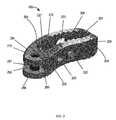
- FIG. 2is a diagrammatic representation of an intervertebral spacer, in accordance with certain embodiments of the present application.
- FIG. 3A to 3Care diagrammatic representations of coupling of an intervertebral spacer with an insertion tool, in accordance with certain configurations of the present application.
- FIG. 4is a diagrammatic view of an intervertebral spacer, in accordance with certain embodiments of the present application.
- FIG. 5Ais a posterior-side view of an intervertebral spacer, in accordance with certain embodiments of the present application.
- FIG. 5Bis a posterior-side view of an intervertebral spacer, in accordance with certain embodiments of the present application.
- FIG. 5Cis a trailing end side view of an intervertebral spacer, in accordance with certain embodiments of the present application.
- FIG. 5Dis a trailing end side posterior-side view of an intervertebral spacer, in accordance with certain embodiments of the present application.
- FIG. 6is a superior-side view of an intervertebral spacer, in accordance with certain embodiments of the present application.
- FIG. 7is a diagrammatic view of an intervertebral spacer, in accordance with certain embodiments of the present application.
- FIG. 8is a diagrammatic view of an intervertebral spacer, in accordance with certain embodiments of the present application.
- FIG. 1illustrates one typical environment in which intervertebral spacers may be used in accordance with the principles of the present disclosure.
- the spacer 102is shown on top of a vertebrae body 104 .
- the spinous process 106is located posteriorally with respect to the body 104 .
- the transverse process 108 and the lamina 110are located between the body 104 and the spinous process 106 .
- the second vertebrae body positioned over top of the spacer 102is not shown in FIG. 1 for purposes of clarity. However, as is well known to one of ordinary skill, the spacer 102 is used in this manner to separate two adjacent vertebrae bodies.
- the spacer 102 of FIG. 1is generally kidney-shaped and includes contours that roughly follow the shape of the vertebrae body 104 . In certain configurations, spacer 102 is rectangular in shape. For purposes of orientation, the posterior portion 202 of the spacer 102 is located closer to the spinous process 106 and the anterior portion 204 is located away from the spinous process 106 . This orientation is for purposes of providing a consistent frame of reference and is not intended to be interpreted as a limitation of the present disclosure.
- the spacer 102may be used in a variety of configurations; however, the configuration of FIG. 1 is a typical configuration with the spacer 102 located near the anterior region of the vertebrae body 104 . During surgery, a surgeon will place the spacer 102 at this location and may do so using a variety of techniques.
- the arrow 112indicates a direction generally referred to, with respect to spacer implants, as transforaminal. This arrow 112 indicates the general direction in which the spacer 102 is inserted between two adjacent vertebrae bodies.
- Advantageous attributes of the present disclosureallow this direction 112 to widely vary, even during surgery, to allow a surgeon great flexibility in inserting the spacer 102 .
- the orientation of the major axis 304 of the spacer 102 relative to the direction 112may vary as well.
- the spacer 102is designed for insertion in a patient's body, its material is selected to withstand such an environment without deteriorating or harming the patient.
- Exemplary materials useful in this environmentinclude, but are not limited to, polyether ether ketone, titanium, artificial bone material, and natural bone tissue. Other similar material may be used without departing from the scope of the present disclosure.
- FIGS. 2 to 8show different views of more detailed depictions of various embodiments of the spacer 102 .
- a number of the features described with reference to these figuresare optional but provide certain advantages.
- holesmay be present that permit the insertion of bone-grafting material that helps fuse the spacer to adjacent spinal bodies.
- the spacer surfaces which are adjacent vertebrae bodiesmay be rough, or otherwise “keyed”, to improve the mechanical adherence of the spacer to the bodies. In this way, the spacer is less likely to move or shift once it has been surgically implanted.
- FIG. 2depicts a diagrammatic view of the spacer 102 in which the leading end 206 and the trailing end 208 are visible.
- the trailing end 208has an opening 251 in which the post 252 is positioned.
- the post 252extends across the clearance of the opening 251 .
- the external surface of the post 252is configured to accept an extending portion of an insertion tool (not shown in FIG. 2 ) to torsionally engage a complementary surface of the insertion tool at a plurality of different angles, as will be further described in details.
- the post 252provides an interface with an inserter (not shown in FIG. 2 ) that enables the spacer 102 to rotate while being inserted into the intervertebral space.
- an inserter(not shown in FIG. 2 ) that enables the spacer 102 to rotate while being inserted into the intervertebral space.
- a surgeoncan advantageously use the torsional engagement between the inserter and the post 252 to move the spacer 102 back and forth in the insertion direction and also angle the spacer 102 as needed.
- the surgeonis able to control the amount of torsional coupling between the inserter and the post 252 by selectively torsionally engaging the inserter with the post 252 .
- the spacer 102can be seen as a kidney-shaped cage having an internal cavity 201 . As mentioned previously, this internal cavity 201 may be filled with bone-grafting material if desired.
- the spacer 102includes an anterior side 204 connecting the leading end 206 and the trailing end 208 .
- the spacer 102further includes a posterior side 202 opposite to the anterior side 204 and connecting the leading end 206 to the trailing end 208 .
- the posterior side 202 and the anterior side 204are arcuate and the spacer 102 is substantially kidney-shaped.
- the posterior side 202 and the anterior side 204have different respective radii of curvature, although they may have the same radius in certain embodiments.
- the substantially planar superior side 209is substantially perpendicular to the posterior and the anterior sides 202 , 204 and extends from the leading end 206 to the trailing end 208 .
- the substantially planar inferior side 211is opposite to the superior side 209 and is also substantially perpendicular to the posterior and the anterior sides 202 , 204 and extends from the leading end 206 to the trailing end 208 .
- the superior side 209comprises teeth 212 , 214 .
- Teeth 212 , 214 on the outside surfaces of the superior side 209 and the inferior side 211are exemplary in nature and can vary in numerous ways, or even be absent, without departing from the scope of the present disclosure.
- teeth 212 , 214may be pointed at their peaks (in cross-section) and have rounded, pointed, or squared valleys between adjacent peaks.
- the slope of the sides of the teeth 212 , 214may vary as well as the spacing between the teeth 212 , 214 .
- the height of the teeth 212 , 214may vary as well. Because the posterior side 202 and anterior side 204 may be arcuate shaped, the teeth 212 , 214 may be spaced variably such that they are closer at their posterior side end that at their anterior side end.
- the post 252is attached to the superior side 209 within a superior-side recess 254 and to the inferior side 211 within an inferior-side recess 256 .
- the recesses 254 , 256may be in the form of one or more through holes in the superior side 209 and the inferior side 211 , wherein the post 252 is fitted.
- recesses 254 , 256may be present on the interior surfaces of the superior side 209 and the inferior side 211 wherein the post 252 is fitted.
- the recesses 254 , 256are positioned at the trailing end 208 , offset from the opening 251 in the direction of the leading end 206 .
- the offsettinghelps secure movement of the spacer 102 using an external tool (not shown in FIG. 2 ).
- the post 252is made of a polymeric material or a metallic material that can additionally be used as an X-ray marker.
- the metallic post 252will further serve as a removal engagement point for the spacer 102 if need be due to higher strength than the other portions of the spacer 102 .
- the spacer 102may also include features that improve ease of insertion, osseointegration with osseoconduction and surface interdigitations for improved mechanical interlocking to the fusion mass.
- the post 252can be press-fitted, threaded or attached by other means into the body. In certain embodiments, the post 252 provides structural strength to the spacer 102 .
- the outside surface of the post 252is shaped to complement a corresponding gripping surface of an external inserting tool.
- the post 252may be cylindrical in shape, or may have a hexagonal or rectangular outside surface to facilitate a firm grip with an external inserting tool.
- the trailing end 208includes an exterior surface 210 that has a tapering shape with an opening 251 to enable insertion of an external insertion tool to hold the post 252 during operation.
- the opening 251extends between the superior side 209 and the inferior side 211 to be wide enough to allow the insertion tool to be inserted. Furthermore, the opening 251 extends between the posterior side 202 and the anterior side 212 to allow rotation of the insertion tool in its inserted position, as will be described in more detail later.
- holes 220 , 222 in the posterior side 202 and holes 221 , 223 in the anterior side 204are useful in providing access for bone-grafting material or other substances to be injected into the spacer 102 or may allow for vascularization after implant.
- FIGS. 3A to 3Cdepict views in which an external inserter 302 is coupled to the post 252 .
- the shape of the surface of the post 252conforms with the gripping surface of the inserter 302 .
- the surface of the post 252is circular, hexagonal or square and so on.
- FIG. 3Adepicts the external inserter 302 engaged in the engaging mechanism of the spacer (e.g., post 252 ).
- the external inserter 302is generally aligned with the major axis 304 of the spacer 102 extending from the trailing end 208 to the leading end 206 .
- such an alignment of the external inserter 302 with the major axis 304 of the spacer 102enables a surgeon to insert the spacer 102 into an intervertebral gap at a desired angle.
- a surgeonmay exert force in the direction of arrow 306 to achieve insertion of the spacer 102 in the direction of the major axis 304 in the intervertebral space.
- a surgeonmay exert force in the direction opposite to arrow 306 to move the spacer 102 outwardly from the intervertebral space.
- FIG. 3Bdepicts, for illustration purpose only, the external inserter 302 and the spacer 102 cut open in a plane parallel to and midway between the superior side 209 and the inferior side 211 , exposing the internal cavity 201 .
- a surgeonmay alter the insertion angle of the spacer 102 during surgery in numerous and various positions to account for possible variations and conditions that might arise during surgery. Even though such angular adjustability is provided, the external inserter 302 and the spacer 102 remain fastened together during insertion and angular adjustment so that re-aligning the angle between one another, during or after an angular adjustment, may be easily accomplished without difficulty or unwanted separation.
- FIG. 3Cdepicts the spacer 102 of FIG. 3B , rotated by about 90 degrees in the direction of arrow 308 with respect to the position depicted in FIG. 3B .
- the external inserter 302is depicted as aligned with the minor axis 310 of the spacer 102 .
- the engaging mechanism of the spacer 102e.g., the post 252
- the external inserter 302may be rotated by simply using torque while the spacer 102 is firmly held in position such as in the intervertebral space (not shown in FIG. 3C ).
- a surgeoncan direct the spacer 102 to a position within an intervertebral space by torsionally engaging the external inserter 302 with the post 252 .
- the spacer 102can rotate within the intervertebral space around the post 252 freely to the extent permitted by the geometry of the trailing end 208 .
- the clearance geometry of the trailing end 208determines the amount of angulation the spacer 102 can go through within the intervertebral space.
- a surgeoncan approach an intervertebral space and place the spacer 102 within the intervertebral space at a desired orientation and then disengage the spacer 102 from the external inserter 302 , thereby allowing the spacer 102 to rotate within the intervertebral space without the need to change the orientation of the external inserter 302 .
- FIG. 4depicts another embodiment 400 of the spacer 102 wherein the post 252 is covered by a sleeve 402 .
- the sleeve 402is configured to have matching features to couple firmly with the external inserter 302 (e.g., matching shape or matching groves).
- the sleeve 402may be configured to freely rotate about the post 252 . When the sleeve 402 is able to freely rotate, a surgeon is still able to move the spacer 102 using the external inserter 302 due to a frictional contact between the spacer 102 and the external inserter 302 .
- the spacer 102 and the external inserter 302are provided with complementary interlocking features (e.g., male/female connection) to establish a secure contact allowing movement of the spacer 102 by exertion of force from the external inserter 302 .
- an interlocking featuresuch as the groove 257
- a matching interlocking featureis provided on the external inserter 302 (not shown in FIG. 4 ) to establish a secure connection between the sleeve 402 and the external inserter 302 .
- an interlocking featuresuch as the groove 257
- FIG. 5Adepicts a posterior side view of the spacer embodiment 400 .
- profiles of teeth 212 , 214are visible.
- the posterior side 202has a smooth surface.
- the holes 220 , 222 in the posterior side 202are aligned with the holes 221 , 223 in the anterior side 204 , thereby allowing ready fusion of bone.
- the holes 220 , 221 , 222 , 223are depicted as elliptical, but may be of other shapes such as circular or multiple openings.
- teeth 212 , 214have varying heights and widths in certain embodiments. In the depicted embodiment, the teeth towards the center of the spacer 102 are broader and less sharp compared to the teeth towards the trailing end 208 and the leading end 206 .
- the superior side 209 and the inferior side 211are shaped to be bulging at the center, depicted as height H 0 , with a slight taper, bringing the superior side 209 and the inferior side 211 closer to each other at the trailing end 208 and the leading end 206 .
- the spacer 102are omitted in FIG. 5B (e.g., post 252 , teeth 212 , 214 ) to depict the tapering feature with clarity.
- the slight taperis optional and may be useful in achieving a better fit in the intervertebral space by allowing a surgeon to better position the spacer 102 by sliding in a tapering end first.
- the height H 1 of the anterior side 204is greater than the height H 2 of the posterior side 202 such that the superior side 209 slopes downwardly from the anterior side 204 to the posterior side 202 .
- the spacer 102are omitted in FIG. 5C (e.g., post 252 , teeth 212 , 214 ) to depict the height feature with clarity.
- the slight taperis optional and may be useful in achieving a better fit in the intervertebral space by allowing a surgeon to better position the spacer 102 by sliding in a tapering end first.
- the height H 1 of the anterior side 204is greater than the height H 2 of the posterior side 202 such that the inferior side 211 slopes upwardly from the anterior side 204 to the posterior side 202 .
- the spacer 102are omitted in FIG. 5C (e.g., post 252 , teeth 212 , 214 ) to depict the height feature with clarity.
- the slight taperis optional and may be useful in achieving a better fit in the intervertebral space by allowing a surgeon to better position the spacer 102 by sliding in a tapering end first.
- FIG. 6depicts a view from the superior side 209 .
- Teeth 212 , 214 on the superior side 209are arranged in two groups. In the first group 608 that is closer to the trailing end 208 , the teeth are angled by ⁇ degrees to point towards the leading end 206 . In the second group 606 that is closer to the leading end 206 , teeth are angled by ⁇ degrees to point towards the trailing end 208 .
- the tooth pattern in group 606aids rotation of the leading end 206 towards the concave side of the spacer 102 while the tooth pattern in group 608 on the trailing side 208 of the spacer 102 will aid rotation of towards the convex side of the spacer 102 .
- the spacer 102travels along a non-liner insertion path until its final position which is rotated from the initial position.
- the leading end 206comprises a generally arcuate portion 618 and a substantially straight portion 616 adjoining the arcuate portion 618 .
- the arcuate portion 618may be adjoining the posterior side 202 , as depicted in FIG. 6 , or the anterior side 204 .
- the trailing end 208comprises a generally arcuate portion 622 and a substantially straight portion 620 adjoining the arcuate portion 618 .
- Such shaping of the leading end 206 and the trailing end 208aids the insertion and fitting of the spacer 102 into the intervertebral spacing.
- FIG. 7depicts another embodiment 700 of the spacer 102 , in a view similar to FIG. 2 .
- No engaging mechanismis depicted (e.g., the post 252 or the sleeve 402 ) because the superior and the inferior recesses 254 , 256 may be configured to accept either a post 252 or a post 252 with sleeve 402 around it.
- the spacer 102includes interdigitation features 702 comprising an array of depressions for improved osseointegration. As the bone fusion mass is conducted around the spacer 102 , the interdigitation features 702 provide additional mechanical interlocking of the bone to the spacer 102 .
- FIG. 8depicts another exemplary embodiment 800 of spacer 102 .
- No engaging mechanismis depicted (e.g., the post 252 or the sleeve 402 ) because the superior and the inferior recesses 254 , 256 may be configured to accept either a post 252 or a post 252 with sleeve 402 around it.
- the depicted embodimentshows additional interdigitation features 802 that include wavy texture to the anterior and the posterior surfaces 204 , 202 .
- the interdigitation features 802can also be used for ease of insertion in applications in which the spacer 102 needs to be turned around bony or tissue structures along the path of insertion. For example, in the embodiment depicted in FIG.
- the interdigitation features 802are in the form of vertical rails on the posterior side 202 provide resistance to forward movement aiding device rotation about the posterior side 202 while outer horizontal rails 804 circumscribe the convex perimeter of the leading end 106 to act as rails in which the spacer 102 may slide along the out annulus of the disc space, aiding insertion. Additionally the interior surfaces of the spacer 102 defining the internal cavity 201 may also have similar interdigitation features (not depicted in FIG. 8 ).
- a spacer 102may be made from a biocompatible material such as titanium, cobalt chromium, tantalum, steel, and nitinol or polymers such as PEEK, PEEK reinforced, PEEK filled, and PCU.
- an inserter 302engages a sleeve 402 that can rotate freely about the interbody post 252 .
- the post 252comprises a metallic biocompatible material such as titanium, cobalt chromium, tantalum, steel, and nitinol.
- the post 252comprises a biocompatible polymer such as PEEK, PEEK reinforced, PEEK filled, PCU and so forth.
- the post 252improves the mechanical strength of the spacer 102 by providing spacing support between opposite superior and inferior sides 209 , 211 .
- a metallic post 252can be used as an X-ray marker for the spacer 102 .
- the post 252can be used as a hinge for a removal instrument.
- the spacer 102includes inferior and superior patterned teeth 212 , 214 , 502 , 504 to ease insertion.
- the spacer 102comprises a pattern on the leading end 206 (e.g., teeth pattern or pattern 804 ), helping with rotation of the leading end 206 towards the implant's concave side.
- teeth 214 , 504 closer to the leading end 206are patterned at an angle from 0 to 90 degrees relative to the insertion path (the major axis 304 of the spacer 102 ) for a clockwise rotation of the spacer 102 .
- the teeth 212 , 502 closer to the trailing end 208as depicted in FIG.
- the outer surface teeth patterns 212 , 214 , 502 , 504are mirrored so that the spacer 102 rotates about the concave side in either a clockwise or counterclockwise direction depending on the insertion position or reference.
- a spacer 102Another disclosed feature of a spacer 102 relates to interdigitation features for improved osseointegration or mechanical interlocking.
- the interdigitationsmay exist on the outer or inner surfaces to mechanically interlock external and internal bone formations.
- the interdigitation featureshas different patterns on the anterior and the posterior sides 202 , 204 .
- Certain embodiments of a spacer 102include a coating with osseoconductive texture.
- the coating layermay be tailored to provide a surface energy suitable for bone cell attachment.
- the coatingis deposited using chemical or physical deposition such as an Atomic Fusion Deposition process.
- the coatingis applied using a thermal spray such as titanium plasma spray or Hydroxyapatite (HA) plasma spray.
Landscapes
- Health & Medical Sciences (AREA)
- Engineering & Computer Science (AREA)
- Biomedical Technology (AREA)
- Orthopedic Medicine & Surgery (AREA)
- Transplantation (AREA)
- Neurology (AREA)
- Heart & Thoracic Surgery (AREA)
- Oral & Maxillofacial Surgery (AREA)
- Cardiology (AREA)
- Vascular Medicine (AREA)
- Life Sciences & Earth Sciences (AREA)
- Animal Behavior & Ethology (AREA)
- General Health & Medical Sciences (AREA)
- Public Health (AREA)
- Veterinary Medicine (AREA)
- Physical Education & Sports Medicine (AREA)
- Prostheses (AREA)
Abstract
Description
Claims (10)
Priority Applications (2)
| Application Number | Priority Date | Filing Date | Title |
|---|---|---|---|
| US12/753,759US8409290B2 (en) | 2006-03-08 | 2010-04-02 | Interbody device for spinal applications |
| PCT/US2011/030984WO2011123807A1 (en) | 2010-04-02 | 2011-04-01 | Interbody device for spinal applications |
Applications Claiming Priority (4)
| Application Number | Priority Date | Filing Date | Title |
|---|---|---|---|
| US11/371,539US20070213826A1 (en) | 2006-03-08 | 2006-03-08 | Intervertebral spacer and insertion tool providing multiple angles of insertion |
| US91961607A | 2007-10-30 | 2007-10-30 | |
| US91961507A | 2007-10-30 | 2007-10-30 | |
| US12/753,759US8409290B2 (en) | 2006-03-08 | 2010-04-02 | Interbody device for spinal applications |
Related Parent Applications (1)
| Application Number | Title | Priority Date | Filing Date |
|---|---|---|---|
| US11/371,539Continuation-In-PartUS20070213826A1 (en) | 2006-03-08 | 2006-03-08 | Intervertebral spacer and insertion tool providing multiple angles of insertion |
Publications (2)
| Publication Number | Publication Date |
|---|---|
| US20100191337A1 US20100191337A1 (en) | 2010-07-29 |
| US8409290B2true US8409290B2 (en) | 2013-04-02 |
Family
ID=44712657
Family Applications (1)
| Application Number | Title | Priority Date | Filing Date |
|---|---|---|---|
| US12/753,759Active2027-02-15US8409290B2 (en) | 2006-03-08 | 2010-04-02 | Interbody device for spinal applications |
Country Status (2)
| Country | Link |
|---|---|
| US (1) | US8409290B2 (en) |
| WO (1) | WO2011123807A1 (en) |
Cited By (52)
| Publication number | Priority date | Publication date | Assignee | Title |
|---|---|---|---|---|
| US20130110247A1 (en)* | 2011-11-01 | 2013-05-02 | Amedica Corporation | Implants with a Connectable Insert and Related Systems and Methods |
| US20140058518A1 (en)* | 2008-10-13 | 2014-02-27 | Marcin Niemiec | Articulating Spacer |
| US9034045B2 (en) | 2013-03-15 | 2015-05-19 | Globus Medical, Inc | Expandable intervertebral implant |
| US9149367B2 (en) | 2013-03-15 | 2015-10-06 | Globus Medical Inc | Expandable intervertebral implant |
| US9186258B2 (en) | 2013-03-15 | 2015-11-17 | Globus Medical, Inc. | Expandable intervertebral implant |
| US9204972B2 (en) | 2013-03-01 | 2015-12-08 | Globus Medical, Inc. | Articulating expandable intervertebral implant |
| US9351848B2 (en) | 2010-09-03 | 2016-05-31 | Globus Medical, Inc. | Expandable fusion device and method of installation thereof |
| US9402739B2 (en) | 2014-02-07 | 2016-08-02 | Globus Medical, Inc. | Variable lordosis spacer and related methods of use |
| US9402738B2 (en) | 2013-02-14 | 2016-08-02 | Globus Medical, Inc. | Devices and methods for correcting vertebral misalignment |
| US9566168B2 (en) | 2010-09-03 | 2017-02-14 | Globus Medical, Inc. | Expandable fusion device and method of installation thereof |
| US9585765B2 (en) | 2013-02-14 | 2017-03-07 | Globus Medical, Inc | Devices and methods for correcting vertebral misalignment |
| US9724207B2 (en) | 2003-02-14 | 2017-08-08 | DePuy Synthes Products, Inc. | In-situ formed intervertebral fusion device and method |
| US9782265B2 (en) | 2013-02-15 | 2017-10-10 | Globus Medical, Inc | Articulating and expandable vertebral implant |
| US9949769B2 (en) | 2004-03-06 | 2018-04-24 | DePuy Synthes Products, Inc. | Dynamized interspinal implant |
| US10004609B2 (en) | 2016-09-23 | 2018-06-26 | Warsaw Orthopedic, Inc. | Surgical instrument and method |
| US10105239B2 (en) | 2013-02-14 | 2018-10-23 | Globus Medical, Inc. | Devices and methods for correcting vertebral misalignment |
| US10117754B2 (en) | 2013-02-25 | 2018-11-06 | Globus Medical, Inc. | Expandable intervertebral implant |
| US20190105179A1 (en)* | 2008-12-26 | 2019-04-11 | Pantheon Spinal, Llc | Method of retroperitoneal lateral insertion of spinal implants |
| US10433974B2 (en) | 2003-06-30 | 2019-10-08 | DePuy Synthes Products, Inc. | Intervertebral implant with conformable endplate |
| US10478313B1 (en) | 2014-01-10 | 2019-11-19 | Nuvasive, Inc. | Spinal fusion implant and related methods |
| USD907771S1 (en) | 2017-10-09 | 2021-01-12 | Pioneer Surgical Technology, Inc. | Intervertebral implant |
| US10888433B2 (en) | 2016-12-14 | 2021-01-12 | DePuy Synthes Products, Inc. | Intervertebral implant inserter and related methods |
| US10940016B2 (en) | 2017-07-05 | 2021-03-09 | Medos International Sarl | Expandable intervertebral fusion cage |
| US10966840B2 (en) | 2010-06-24 | 2021-04-06 | DePuy Synthes Products, Inc. | Enhanced cage insertion assembly |
| US10973652B2 (en) | 2007-06-26 | 2021-04-13 | DePuy Synthes Products, Inc. | Highly lordosed fusion cage |
| US20210290408A1 (en)* | 2008-10-13 | 2021-09-23 | Globus Medical, Inc. | Intervertebral spacer |
| US11147682B2 (en) | 2017-09-08 | 2021-10-19 | Pioneer Surgical Technology, Inc. | Intervertebral implants, instruments, and methods |
| US11273050B2 (en) | 2006-12-07 | 2022-03-15 | DePuy Synthes Products, Inc. | Intervertebral implant |
| US11344424B2 (en) | 2017-06-14 | 2022-05-31 | Medos International Sarl | Expandable intervertebral implant and related methods |
| US11364057B2 (en) | 2009-03-27 | 2022-06-21 | Spinal Elements, Inc. | Flanged interbody fusion device |
| US11382769B2 (en) | 2018-09-20 | 2022-07-12 | Spinal Elements, Inc. | Spinal implant device |
| US11426286B2 (en) | 2020-03-06 | 2022-08-30 | Eit Emerging Implant Technologies Gmbh | Expandable intervertebral implant |
| US11426290B2 (en) | 2015-03-06 | 2022-08-30 | DePuy Synthes Products, Inc. | Expandable intervertebral implant, system, kit and method |
| US11446155B2 (en) | 2017-05-08 | 2022-09-20 | Medos International Sarl | Expandable cage |
| US11446156B2 (en) | 2018-10-25 | 2022-09-20 | Medos International Sarl | Expandable intervertebral implant, inserter instrument, and related methods |
| US11452607B2 (en) | 2010-10-11 | 2022-09-27 | DePuy Synthes Products, Inc. | Expandable interspinous process spacer implant |
| US11497619B2 (en) | 2013-03-07 | 2022-11-15 | DePuy Synthes Products, Inc. | Intervertebral implant |
| US11510788B2 (en) | 2016-06-28 | 2022-11-29 | Eit Emerging Implant Technologies Gmbh | Expandable, angularly adjustable intervertebral cages |
| US11596523B2 (en) | 2016-06-28 | 2023-03-07 | Eit Emerging Implant Technologies Gmbh | Expandable and angularly adjustable articulating intervertebral cages |
| US11602438B2 (en) | 2008-04-05 | 2023-03-14 | DePuy Synthes Products, Inc. | Expandable intervertebral implant |
| US11607321B2 (en) | 2009-12-10 | 2023-03-21 | DePuy Synthes Products, Inc. | Bellows-like expandable interbody fusion cage |
| US11612491B2 (en) | 2009-03-30 | 2023-03-28 | DePuy Synthes Products, Inc. | Zero profile spinal fusion cage |
| US11654033B2 (en) | 2010-06-29 | 2023-05-23 | DePuy Synthes Products, Inc. | Distractible intervertebral implant |
| US11737881B2 (en) | 2008-01-17 | 2023-08-29 | DePuy Synthes Products, Inc. | Expandable intervertebral implant and associated method of manufacturing the same |
| US11752009B2 (en) | 2021-04-06 | 2023-09-12 | Medos International Sarl | Expandable intervertebral fusion cage |
| US11850160B2 (en) | 2021-03-26 | 2023-12-26 | Medos International Sarl | Expandable lordotic intervertebral fusion cage |
| US11911284B2 (en) | 2020-11-19 | 2024-02-27 | Spinal Elements, Inc. | Curved expandable interbody devices and deployment tools |
| US11911287B2 (en) | 2010-06-24 | 2024-02-27 | DePuy Synthes Products, Inc. | Lateral spondylolisthesis reduction cage |
| USRE49973E1 (en) | 2013-02-28 | 2024-05-21 | DePuy Synthes Products, Inc. | Expandable intervertebral implant, system, kit and method |
| US12090064B2 (en) | 2022-03-01 | 2024-09-17 | Medos International Sarl | Stabilization members for expandable intervertebral implants, and related systems and methods |
| US12279969B2 (en) | 2020-12-17 | 2025-04-22 | Spinal Elements, Inc. | Spinal implant device |
| US12440346B2 (en) | 2023-03-31 | 2025-10-14 | DePuy Synthes Products, Inc. | Expandable intervertebral implant |
Families Citing this family (56)
| Publication number | Priority date | Publication date | Assignee | Title |
|---|---|---|---|---|
| WO2006058221A2 (en) | 2004-11-24 | 2006-06-01 | Abdou Samy M | Devices and methods for inter-vertebral orthopedic device placement |
| US8409290B2 (en) | 2006-03-08 | 2013-04-02 | Seaspine, Inc. | Interbody device for spinal applications |
| US8088163B1 (en) | 2008-02-06 | 2012-01-03 | Kleiner Jeffrey B | Tools and methods for spinal fusion |
| US8216317B2 (en) | 2008-03-31 | 2012-07-10 | Stryker Spine | Spinal implant apparatus and methods |
| US20210378834A1 (en) | 2008-05-22 | 2021-12-09 | Spinal Surgical Strategies, Inc., A Nevada Corporation D/B/A Kleiner Device Labs | Spinal fusion cage system with inserter |
| USD853560S1 (en) | 2008-10-09 | 2019-07-09 | Nuvasive, Inc. | Spinal implant insertion device |
| US8864654B2 (en) | 2010-04-20 | 2014-10-21 | Jeffrey B. Kleiner | Method and apparatus for performing retro peritoneal dissection |
| US9717403B2 (en) | 2008-12-05 | 2017-08-01 | Jeffrey B. Kleiner | Method and apparatus for performing retro peritoneal dissection |
| US8366748B2 (en) | 2008-12-05 | 2013-02-05 | Kleiner Jeffrey | Apparatus and method of spinal implant and fusion |
| USD656610S1 (en) | 2009-02-06 | 2012-03-27 | Kleiner Jeffrey B | Spinal distraction instrument |
| US9247943B1 (en) | 2009-02-06 | 2016-02-02 | Kleiner Intellectual Property, Llc | Devices and methods for preparing an intervertebral workspace |
| US20110029085A1 (en)* | 2009-07-31 | 2011-02-03 | Warsaw Orthopedic, Inc. | Flexible spinal implant |
| US9173694B2 (en) | 2009-09-18 | 2015-11-03 | Spinal Surgical Strategies, Llc | Fusion cage with combined biological delivery system |
| US9060877B2 (en) | 2009-09-18 | 2015-06-23 | Spinal Surgical Strategies, Llc | Fusion cage with combined biological delivery system |
| US8906028B2 (en) | 2009-09-18 | 2014-12-09 | Spinal Surgical Strategies, Llc | Bone graft delivery device and method of using the same |
| US9186193B2 (en) | 2009-09-18 | 2015-11-17 | Spinal Surgical Strategies, Llc | Fusion cage with combined biological delivery system |
| USD723682S1 (en) | 2013-05-03 | 2015-03-03 | Spinal Surgical Strategies, Llc | Bone graft delivery tool |
| USD750249S1 (en) | 2014-10-20 | 2016-02-23 | Spinal Surgical Strategies, Llc | Expandable fusion cage |
| US8685031B2 (en) | 2009-09-18 | 2014-04-01 | Spinal Surgical Strategies, Llc | Bone graft delivery system |
| US10245159B1 (en) | 2009-09-18 | 2019-04-02 | Spinal Surgical Strategies, Llc | Bone graft delivery system and method for using same |
| US20170238984A1 (en) | 2009-09-18 | 2017-08-24 | Spinal Surgical Strategies, Llc | Bone graft delivery device with positioning handle |
| US10973656B2 (en) | 2009-09-18 | 2021-04-13 | Spinal Surgical Strategies, Inc. | Bone graft delivery system and method for using same |
| US9629729B2 (en) | 2009-09-18 | 2017-04-25 | Spinal Surgical Strategies, Llc | Biological delivery system with adaptable fusion cage interface |
| US9028553B2 (en) | 2009-11-05 | 2015-05-12 | DePuy Synthes Products, Inc. | Self-pivoting spinal implant and associated instrumentation |
| US8764806B2 (en) | 2009-12-07 | 2014-07-01 | Samy Abdou | Devices and methods for minimally invasive spinal stabilization and instrumentation |
| US8900309B2 (en) | 2010-08-31 | 2014-12-02 | Meditech Spine, Llc | Spinal implants |
| US8425529B2 (en) | 2010-09-30 | 2013-04-23 | Stryker Spine | Instrument for inserting surgical implant with guiding rail |
| US8603175B2 (en) | 2010-09-30 | 2013-12-10 | Stryker Spine | Method of inserting surgical implant with guiding rail |
| US8858637B2 (en) | 2010-09-30 | 2014-10-14 | Stryker Spine | Surgical implant with guiding rail |
| US8512408B2 (en) | 2010-12-17 | 2013-08-20 | Warsaw Orthopedic, Inc. | Flexiable spinal implant |
| ES2629031T3 (en)* | 2011-04-29 | 2017-08-07 | Medacta International S.A. | Intervertebral implant for fusion between two vertebral bodies of a spine and the corresponding positioning instrument |
| AT12506U1 (en)* | 2011-05-27 | 2012-06-15 | Sabitzer Ronald J Dr | IMPLANT |
| US8845728B1 (en) | 2011-09-23 | 2014-09-30 | Samy Abdou | Spinal fixation devices and methods of use |
| US9132021B2 (en) | 2011-10-07 | 2015-09-15 | Pioneer Surgical Technology, Inc. | Intervertebral implant |
| US20130226240A1 (en) | 2012-02-22 | 2013-08-29 | Samy Abdou | Spinous process fixation devices and methods of use |
| US9198767B2 (en) | 2012-08-28 | 2015-12-01 | Samy Abdou | Devices and methods for spinal stabilization and instrumentation |
| US9320617B2 (en) | 2012-10-22 | 2016-04-26 | Cogent Spine, LLC | Devices and methods for spinal stabilization and instrumentation |
| US10022245B2 (en) | 2012-12-17 | 2018-07-17 | DePuy Synthes Products, Inc. | Polyaxial articulating instrument |
| US20140277485A1 (en)* | 2013-03-14 | 2014-09-18 | Ranier Limited | Intervertebral fusion implant cage |
| US9149366B2 (en)* | 2013-03-14 | 2015-10-06 | Warsaw Orthopedic, Inc. | Adaptable interbody implant and methods of use |
| TWI566739B (en)* | 2013-09-24 | 2017-01-21 | Baui Biotech Co Ltd | Improved interbody fusion device and implant instrument and method of operation thereof |
| US9526629B2 (en)* | 2013-09-27 | 2016-12-27 | Amedica Corporation | Spinal implants and related instruments and methods |
| US10857003B1 (en) | 2015-10-14 | 2020-12-08 | Samy Abdou | Devices and methods for vertebral stabilization |
| USD797290S1 (en) | 2015-10-19 | 2017-09-12 | Spinal Surgical Strategies, Llc | Bone graft delivery tool |
| US10744000B1 (en) | 2016-10-25 | 2020-08-18 | Samy Abdou | Devices and methods for vertebral bone realignment |
| US10973648B1 (en) | 2016-10-25 | 2021-04-13 | Samy Abdou | Devices and methods for vertebral bone realignment |
| US10238503B2 (en) | 2016-11-01 | 2019-03-26 | Warsaw Orthopedic, Inc. | Expandable spinal implant system with a biased tip and method of using same |
| US10357377B2 (en)* | 2017-03-13 | 2019-07-23 | Institute for Musculoskeletal Science and Education, Ltd. | Implant with bone contacting elements having helical and undulating planar geometries |
| US10966843B2 (en) | 2017-07-18 | 2021-04-06 | DePuy Synthes Products, Inc. | Implant inserters and related methods |
| US11045331B2 (en) | 2017-08-14 | 2021-06-29 | DePuy Synthes Products, Inc. | Intervertebral implant inserters and related methods |
| US10973658B2 (en)* | 2017-11-27 | 2021-04-13 | Titan Spine, Inc. | Rotating implant and associated instrumentation |
| US11179248B2 (en) | 2018-10-02 | 2021-11-23 | Samy Abdou | Devices and methods for spinal implantation |
| US11039931B2 (en)* | 2019-02-01 | 2021-06-22 | Globus Medical, Inc. | Intervertebral spinal implant |
| CN109925102A (en)* | 2019-04-12 | 2019-06-25 | 北京大学第三医院 | Lumbar Fusion prosthese |
| US11166825B1 (en)* | 2020-07-01 | 2021-11-09 | Warsaw Orthopedic, Inc. | Spinal implant |
| US11951021B2 (en)* | 2021-11-30 | 2024-04-09 | DePuy Synthes Products, Inc. | Surgical implant position detection |
Citations (114)
| Publication number | Priority date | Publication date | Assignee | Title |
|---|---|---|---|---|
| DE2263842A1 (en) | 1972-12-28 | 1974-07-04 | Hoffmann Daimler Siegfried Dr | DISC PROTHESIS |
| US5071437A (en) | 1989-02-15 | 1991-12-10 | Acromed Corporation | Artificial disc |
| US5431658A (en) | 1994-02-14 | 1995-07-11 | Moskovich; Ronald | Facilitator for vertebrae grafts and prostheses |
| US5676701A (en) | 1993-01-14 | 1997-10-14 | Smith & Nephew, Inc. | Low wear artificial spinal disc |
| US5733290A (en) | 1995-12-21 | 1998-03-31 | Johnson & Johnson Professional, Inc. | Quick-release tibial alignment handle |
| US5755796A (en) | 1996-06-06 | 1998-05-26 | Ibo; Ivo | Prosthesis of the cervical intervertebralis disk |
| US5888222A (en) | 1995-10-16 | 1999-03-30 | Sdgi Holding, Inc. | Intervertebral spacers |
| US5899941A (en) | 1997-12-09 | 1999-05-04 | Chubu Bearing Kabushiki Kaisha | Artificial intervertebral disk |
| US6033438A (en) | 1997-06-03 | 2000-03-07 | Sdgi Holdings, Inc. | Open intervertebral spacer |
| US6113638A (en) | 1999-02-26 | 2000-09-05 | Williams; Lytton A. | Method and apparatus for intervertebral implant anchorage |
| US6113637A (en) | 1998-10-22 | 2000-09-05 | Sofamor Danek Holdings, Inc. | Artificial intervertebral joint permitting translational and rotational motion |
| US6193757B1 (en) | 1998-10-29 | 2001-02-27 | Sdgi Holdings, Inc. | Expandable intervertebral spacers |
| US6206924B1 (en) | 1999-10-20 | 2001-03-27 | Interpore Cross Internat | Three-dimensional geometric bio-compatible porous engineered structure for use as a bone mass replacement or fusion augmentation device |
| US6235059B1 (en) | 1996-04-03 | 2001-05-22 | Scient'x (Societe A Responsabilite Limitee) | Intersomatic setting and fusion system |
| US6258125B1 (en) | 1998-08-03 | 2001-07-10 | Synthes (U.S.A.) | Intervertebral allograft spacer |
| US20010020170A1 (en) | 1997-01-02 | 2001-09-06 | Zucherman James F. | Spinal implants, insertion instruments, and methods of use |
| US6319257B1 (en) | 1999-12-20 | 2001-11-20 | Kinamed, Inc. | Inserter assembly |
| US6368354B2 (en) | 1999-10-07 | 2002-04-09 | Exactech, Inc. | Acetabular bearing assembly for total hip joints |
| US6368350B1 (en) | 1999-03-11 | 2002-04-09 | Sulzer Spine-Tech Inc. | Intervertebral disc prosthesis and method |
| US6423095B1 (en) | 1995-10-16 | 2002-07-23 | Sdgi Holdings, Inc. | Intervertebral spacers |
| US6478801B1 (en) | 2001-07-16 | 2002-11-12 | Third Millennium Engineering, Llc | Insertion tool for use with tapered trial intervertebral distraction spacers |
| US6482233B1 (en) | 1998-01-29 | 2002-11-19 | Synthes(U.S.A.) | Prosthetic interbody spacer |
| US6520993B2 (en) | 2000-12-29 | 2003-02-18 | Depuy Acromed, Inc. | Spinal implant |
| US20030045939A1 (en) | 2001-08-24 | 2003-03-06 | Simon Casutt | Artificial intervertebral disc |
| US20030069586A1 (en) | 2001-07-16 | 2003-04-10 | Errico Joseph P. | Instrumentation and methods for use in implanting an artificial intervertebral disc |
| US20030100950A1 (en) | 2000-03-22 | 2003-05-29 | Olivier Moret | Cage-type intervertebral implant |
| US6572619B2 (en) | 2001-02-23 | 2003-06-03 | Albert N. Santilli | Cage plate for spinal fusion and method of operation |
| US6579318B2 (en) | 2000-06-12 | 2003-06-17 | Ortho Development Corporation | Intervertebral spacer |
| US6595998B2 (en) | 2001-03-08 | 2003-07-22 | Spinewave, Inc. | Tissue distraction device |
| US6635086B2 (en) | 2000-05-30 | 2003-10-21 | Blacksheep Technologies Incorporated | Implant for placement between cervical vertebrae |
| WO2004000177A1 (en) | 2002-06-25 | 2003-12-31 | Eurosurgical Sa | Device for the placement of a reversible intersomatic cage between vertebral bodies |
| US6673075B2 (en) | 2001-02-23 | 2004-01-06 | Albert N. Santilli | Porous intervertebral spacer |
| US6706068B2 (en) | 2002-04-23 | 2004-03-16 | Bret A. Ferree | Artificial disc replacements with natural kinematics |
| US6719794B2 (en) | 2001-05-03 | 2004-04-13 | Synthes (U.S.A.) | Intervertebral implant for transforaminal posterior lumbar interbody fusion procedure |
| US6736849B2 (en) | 1998-03-11 | 2004-05-18 | Depuy Products, Inc. | Surface-mineralized spinal implants |
| US20040097929A1 (en) | 1998-10-28 | 2004-05-20 | Branch Charles L. | Interbody fusion grafts and instrumentation |
| US6743257B2 (en) | 2000-12-19 | 2004-06-01 | Cortek, Inc. | Dynamic implanted intervertebral spacer |
| US6758862B2 (en) | 2002-03-21 | 2004-07-06 | Sdgi Holdings, Inc. | Vertebral body and disc space replacement devices |
| USD493225S1 (en) | 2000-06-12 | 2004-07-20 | Ortho Development Corporation | Implant |
| US6793678B2 (en) | 2002-06-27 | 2004-09-21 | Depuy Acromed, Inc. | Prosthetic intervertebral motion disc having dampening |
| USRE38614E1 (en) | 1998-01-30 | 2004-10-05 | Synthes (U.S.A.) | Intervertebral allograft spacer |
| US6805714B2 (en) | 2001-04-02 | 2004-10-19 | Ulrich Gmbh & Co. Kg | Anchorable vertebral implant |
| US20040243241A1 (en) | 2003-05-30 | 2004-12-02 | Naim Istephanous | Implants based on engineered metal matrix composite materials having enhanced imaging and wear resistance |
| US20050027360A1 (en) | 2003-08-01 | 2005-02-03 | Webb Scott A. | Spinal implant |
| US20050038516A1 (en) | 2003-08-14 | 2005-02-17 | Mark Spoonamore | Intervertebral disk prosthesis and method |
| US20050038431A1 (en) | 2003-08-12 | 2005-02-17 | Depuy Acromed, Inc. | Device for insertion of implants |
| US20050071005A1 (en) | 2003-09-30 | 2005-03-31 | Olivier Carli | Intersomatic lumbar implant |
| US20050096745A1 (en) | 2003-10-29 | 2005-05-05 | Eurosurgical Sa | Intersomatic cage for lumbar fusion by transforaminal approach and its cage carrying device |
| US6890355B2 (en) | 2001-04-02 | 2005-05-10 | Gary K. Michelson | Artificial contoured spinal fusion implants made of a material other than bone |
| US6899735B2 (en) | 2002-10-02 | 2005-05-31 | Sdgi Holdings, Inc. | Modular intervertebral prosthesis system |
| US20050143822A1 (en) | 2003-12-29 | 2005-06-30 | Paul David C. | Spinal fusion implant |
| US6964686B2 (en) | 1999-05-17 | 2005-11-15 | Vanderbilt University | Intervertebral disc replacement prosthesis |
| US6966932B1 (en) | 2002-02-05 | 2005-11-22 | Biomet, Inc. | Composite acetabular component |
| US6966929B2 (en) | 2002-10-29 | 2005-11-22 | St. Francis Medical Technologies, Inc. | Artificial vertebral disk replacement implant with a spacer |
| US6974480B2 (en) | 2001-05-03 | 2005-12-13 | Synthes (Usa) | Intervertebral implant for transforaminal posterior lumbar interbody fusion procedure |
| US7048764B2 (en) | 2003-01-07 | 2006-05-23 | Ferree Bret A | Artificial disc replacements with articulating components |
| US7060073B2 (en) | 1999-10-21 | 2006-06-13 | Sdgi Holdings, Inc. | Devices and techniques for a posterior lateral disc space approach |
| US20060149273A1 (en) | 2004-12-06 | 2006-07-06 | Axiomed Spine Corporation | Method and apparatus for replacing a spinal disc |
| US7105023B2 (en) | 2002-01-17 | 2006-09-12 | Concept Matrix, L.L.C. | Vertebral defect device |
| US20060229729A1 (en) | 2003-08-05 | 2006-10-12 | Gordon Charles R | Expandable intervertebral implant for use with instrument |
| US20060229627A1 (en) | 2004-10-29 | 2006-10-12 | Hunt Margaret M | Variable angle spinal surgery instrument |
| USD533277S1 (en) | 2005-11-04 | 2006-12-05 | Quantum Orthopedics, Inc. | Interbody fusion device |
| US7156876B2 (en) | 2002-10-09 | 2007-01-02 | Depuy Acromed, Inc. | Intervertebral motion disc having articulation and shock absorption |
| US7198643B2 (en) | 2003-03-06 | 2007-04-03 | Spinecore, Inc. | Cervical disc replacement |
| US20070093897A1 (en) | 2005-10-21 | 2007-04-26 | Stryker Spine (In France) | System and method for fusion cage implantation |
| US7217293B2 (en) | 2003-11-21 | 2007-05-15 | Warsaw Orthopedic, Inc. | Expandable spinal implant |
| US7229477B2 (en) | 1999-02-25 | 2007-06-12 | Depuy Acromed, Inc. | Spinal fusion implant |
| US7235101B2 (en) | 2003-09-15 | 2007-06-26 | Warsaw Orthopedic, Inc. | Revisable prosthetic device |
| US20070162138A1 (en) | 2005-12-12 | 2007-07-12 | Sdgi Holdings, Inc. | Vertebral implant and insertion tool |
| US20070162128A1 (en) | 2005-12-16 | 2007-07-12 | Sdgi Holdings, Inc. | Intervertebral spacer and insertion tool |
| US7250060B2 (en) | 2004-01-27 | 2007-07-31 | Sdgi Holdings, Inc. | Hybrid intervertebral disc system |
| US20070213826A1 (en) | 2006-03-08 | 2007-09-13 | Seaspine, Inc. | Intervertebral spacer and insertion tool providing multiple angles of insertion |
| US20070225808A1 (en) | 2006-03-22 | 2007-09-27 | Warnick David R | Pivotable interbody spacer |
| US7276082B2 (en) | 2003-09-10 | 2007-10-02 | Warsaw Orthopedic, Inc. | Artificial spinal discs and associated implantation and revision methods |
| US20070282449A1 (en) | 2006-04-12 | 2007-12-06 | Spinalmotion, Inc. | Posterior spinal device and method |
| US20080009880A1 (en) | 2006-03-22 | 2008-01-10 | Warnick David R | Pivotable Vetrebral Spacer |
| US20080051890A1 (en) | 2006-08-11 | 2008-02-28 | Warsaw Orthopedic, Inc. | Intervertebral Implants with Attachable Flanges and Methods of Use |
| US20080077153A1 (en) | 2006-09-22 | 2008-03-27 | Pioneer Surgical Technology, Inc. | System and methods for inserting a spinal disc device into an intervertebral space |
| US20080077247A1 (en)* | 2006-09-22 | 2008-03-27 | Alphatec Spine, Inc. | Spinal spacer |
| USD566276S1 (en) | 2005-11-04 | 2008-04-08 | Spinal Elements, Inc. | Interbody fusion device |
| USRE40260E1 (en) | 2000-03-03 | 2008-04-22 | Scient'x Societe Anonyme | Disk prosthesis for cervical vertebrae |
| US20080275506A1 (en) | 2007-04-27 | 2008-11-06 | Baynham Bret O | Spinal implant |
| US7470273B2 (en) | 2004-06-25 | 2008-12-30 | Ebi, Llc | Tool for intervertebral implant manipulation |
| US7476252B2 (en) | 2002-10-21 | 2009-01-13 | Warsaw Orthopedic, Inc. | System and techniques for restoring and maintaining intervertebral anatomy |
| USD585553S1 (en) | 2007-02-22 | 2009-01-27 | Zimmer Spine, Inc. | Spinal implant |
| US20090054991A1 (en) | 2006-05-02 | 2009-02-26 | Ashok Biyani | Transforaminal lumbar interbody fusion cage |
| US7500991B2 (en) | 2002-12-31 | 2009-03-10 | Depuy Acromed, Inc. | Banana cage |
| US7503933B2 (en) | 1995-06-07 | 2009-03-17 | Warsaw Orthopedic, Inc. | Lordotic interbody spinal fusion implants |
| US20090082868A1 (en) | 2005-05-02 | 2009-03-26 | Cordaro Nicholas M | Prosthesis for restoring motion in an appendage or spinal joint and an intervertebral spacer |
| US7537612B2 (en) | 2003-06-20 | 2009-05-26 | Warsaw Orthopedic, Inc. | Lumbar composite nucleus |
| US20090143859A1 (en) | 2007-11-30 | 2009-06-04 | Mcclellan Iii John W | Maximum support tlif implant |
| US7563284B2 (en) | 2002-08-15 | 2009-07-21 | Synthes Usa, Llc | Intervertebral disc implant |
| US7575580B2 (en) | 2005-04-15 | 2009-08-18 | Warsaw Orthopedic, Inc. | Instruments, implants and methods for positioning implants into a spinal disc space |
| US20090248163A1 (en) | 2008-03-31 | 2009-10-01 | King Emily E | Spinal surgery interbody |
| US20090276049A1 (en) | 2005-01-28 | 2009-11-05 | Peter Weiland | Implant for Transforaminal Intracorporeal Fusion |
| US20100030270A1 (en) | 2007-06-05 | 2010-02-04 | Spartek Medical, Inc. | Dynamic spinal rod assembly and method for dynamic stabilization of the spine |
| US20100121455A1 (en) | 2007-09-07 | 2010-05-13 | Intrinsic Therapeutics, Inc. | Soft tissue impaction methods |
| USD620113S1 (en) | 2008-12-02 | 2010-07-20 | Eminent Spine Llc | Interbody fusion device implant |
| US20100185292A1 (en) | 2009-01-22 | 2010-07-22 | Stephen Hochschuler | Apparatus and method for stabilizing adjacent bone portions |
| US20100191337A1 (en) | 2006-03-08 | 2010-07-29 | Seaspine, Inc. | Interbody device for spinal applications |
| US20100217395A1 (en) | 2006-07-24 | 2010-08-26 | Rudolf Bertagnoli | Intervertebral implant with keel |
| US7815682B1 (en) | 2005-09-24 | 2010-10-19 | Nuvasive, Inc. | Spinal fusion implant and related methods |
| USD629108S1 (en) | 2008-07-26 | 2010-12-14 | Ulrich Gmbh & Co. Kg | Spinal implant |
| USD630749S1 (en) | 2008-10-24 | 2011-01-11 | Alain Tornier | Intersomatic cage |
| US7892239B2 (en) | 2006-03-22 | 2011-02-22 | Beacon Biomedical, Llc | Pivotable interbody spacer system and method |
| US7938857B2 (en) | 2001-11-09 | 2011-05-10 | Zimmer Spine, Inc. | Spinal implant |
| US7959675B2 (en) | 2005-04-08 | 2011-06-14 | G&L Consulting, Llc | Spine implant insertion device and method |
| US7976549B2 (en) | 2006-03-23 | 2011-07-12 | Theken Spine, Llc | Instruments for delivering spinal implants |
| US7988695B2 (en) | 2005-12-21 | 2011-08-02 | Theken Spine, Llc | Articulated delivery instrument |
| US7998212B2 (en) | 2005-09-26 | 2011-08-16 | Warsaw Orthopedic, Inc. | Transforaminal hybrid implant |
| US8021429B2 (en) | 2007-03-08 | 2011-09-20 | Zimmer Spine, Inc. | Deployable segmented TLIF device |
| US8034110B2 (en) | 2006-07-31 | 2011-10-11 | Depuy Spine, Inc. | Spinal fusion implant |
| US8137404B2 (en) | 2006-03-28 | 2012-03-20 | Depuy Spine, Inc. | Artificial disc replacement using posterior approach |
| US8147554B2 (en) | 2008-10-13 | 2012-04-03 | Globus Medical, Inc. | Intervertebral spacer |
- 2010
- 2010-04-02USUS12/753,759patent/US8409290B2/enactiveActive
- 2011
- 2011-04-01WOPCT/US2011/030984patent/WO2011123807A1/enactiveApplication Filing
Patent Citations (126)
| Publication number | Priority date | Publication date | Assignee | Title |
|---|---|---|---|---|
| DE2263842A1 (en) | 1972-12-28 | 1974-07-04 | Hoffmann Daimler Siegfried Dr | DISC PROTHESIS |
| US5071437A (en) | 1989-02-15 | 1991-12-10 | Acromed Corporation | Artificial disc |
| US5676701A (en) | 1993-01-14 | 1997-10-14 | Smith & Nephew, Inc. | Low wear artificial spinal disc |
| US5431658A (en) | 1994-02-14 | 1995-07-11 | Moskovich; Ronald | Facilitator for vertebrae grafts and prostheses |
| US7503933B2 (en) | 1995-06-07 | 2009-03-17 | Warsaw Orthopedic, Inc. | Lordotic interbody spinal fusion implants |
| US5888222A (en) | 1995-10-16 | 1999-03-30 | Sdgi Holding, Inc. | Intervertebral spacers |
| US6423095B1 (en) | 1995-10-16 | 2002-07-23 | Sdgi Holdings, Inc. | Intervertebral spacers |
| US5733290A (en) | 1995-12-21 | 1998-03-31 | Johnson & Johnson Professional, Inc. | Quick-release tibial alignment handle |
| US6235059B1 (en) | 1996-04-03 | 2001-05-22 | Scient'x (Societe A Responsabilite Limitee) | Intersomatic setting and fusion system |
| US5755796A (en) | 1996-06-06 | 1998-05-26 | Ibo; Ivo | Prosthesis of the cervical intervertebralis disk |
| US20010020170A1 (en) | 1997-01-02 | 2001-09-06 | Zucherman James F. | Spinal implants, insertion instruments, and methods of use |
| US6033438A (en) | 1997-06-03 | 2000-03-07 | Sdgi Holdings, Inc. | Open intervertebral spacer |
| US5899941A (en) | 1997-12-09 | 1999-05-04 | Chubu Bearing Kabushiki Kaisha | Artificial intervertebral disk |
| US6482233B1 (en) | 1998-01-29 | 2002-11-19 | Synthes(U.S.A.) | Prosthetic interbody spacer |
| USRE38614E1 (en) | 1998-01-30 | 2004-10-05 | Synthes (U.S.A.) | Intervertebral allograft spacer |
| US6736849B2 (en) | 1998-03-11 | 2004-05-18 | Depuy Products, Inc. | Surface-mineralized spinal implants |
| US6258125B1 (en) | 1998-08-03 | 2001-07-10 | Synthes (U.S.A.) | Intervertebral allograft spacer |
| US6113637A (en) | 1998-10-22 | 2000-09-05 | Sofamor Danek Holdings, Inc. | Artificial intervertebral joint permitting translational and rotational motion |
| US20040097929A1 (en) | 1998-10-28 | 2004-05-20 | Branch Charles L. | Interbody fusion grafts and instrumentation |
| US6193757B1 (en) | 1998-10-29 | 2001-02-27 | Sdgi Holdings, Inc. | Expandable intervertebral spacers |
| US7229477B2 (en) | 1999-02-25 | 2007-06-12 | Depuy Acromed, Inc. | Spinal fusion implant |
| US6800092B1 (en) | 1999-02-26 | 2004-10-05 | Lytton A. Williams | Method and apparatus for intervertebral implant anchorage |
| US6113638A (en) | 1999-02-26 | 2000-09-05 | Williams; Lytton A. | Method and apparatus for intervertebral implant anchorage |
| US6368350B1 (en) | 1999-03-11 | 2002-04-09 | Sulzer Spine-Tech Inc. | Intervertebral disc prosthesis and method |
| US6964686B2 (en) | 1999-05-17 | 2005-11-15 | Vanderbilt University | Intervertebral disc replacement prosthesis |
| US6368354B2 (en) | 1999-10-07 | 2002-04-09 | Exactech, Inc. | Acetabular bearing assembly for total hip joints |
| US6206924B1 (en) | 1999-10-20 | 2001-03-27 | Interpore Cross Internat | Three-dimensional geometric bio-compatible porous engineered structure for use as a bone mass replacement or fusion augmentation device |
| US7060073B2 (en) | 1999-10-21 | 2006-06-13 | Sdgi Holdings, Inc. | Devices and techniques for a posterior lateral disc space approach |
| US6319257B1 (en) | 1999-12-20 | 2001-11-20 | Kinamed, Inc. | Inserter assembly |
| USRE40260E1 (en) | 2000-03-03 | 2008-04-22 | Scient'x Societe Anonyme | Disk prosthesis for cervical vertebrae |
| US20030100950A1 (en) | 2000-03-22 | 2003-05-29 | Olivier Moret | Cage-type intervertebral implant |
| US6699288B2 (en) | 2000-03-22 | 2004-03-02 | Scolio Gmbh | Cage-type intervertebral implant |
| US6635086B2 (en) | 2000-05-30 | 2003-10-21 | Blacksheep Technologies Incorporated | Implant for placement between cervical vertebrae |
| US6579318B2 (en) | 2000-06-12 | 2003-06-17 | Ortho Development Corporation | Intervertebral spacer |
| USD501555S1 (en) | 2000-06-12 | 2005-02-01 | Ortho Development Corporation | Implant |
| USD494274S1 (en) | 2000-06-12 | 2004-08-10 | Ortho Development Corporation | Implant |
| USD493225S1 (en) | 2000-06-12 | 2004-07-20 | Ortho Development Corporation | Implant |
| US6743257B2 (en) | 2000-12-19 | 2004-06-01 | Cortek, Inc. | Dynamic implanted intervertebral spacer |
| US6520993B2 (en) | 2000-12-29 | 2003-02-18 | Depuy Acromed, Inc. | Spinal implant |
| US6673075B2 (en) | 2001-02-23 | 2004-01-06 | Albert N. Santilli | Porous intervertebral spacer |
| US6572619B2 (en) | 2001-02-23 | 2003-06-03 | Albert N. Santilli | Cage plate for spinal fusion and method of operation |
| US6595998B2 (en) | 2001-03-08 | 2003-07-22 | Spinewave, Inc. | Tissue distraction device |
| US6890355B2 (en) | 2001-04-02 | 2005-05-10 | Gary K. Michelson | Artificial contoured spinal fusion implants made of a material other than bone |
| US6805714B2 (en) | 2001-04-02 | 2004-10-19 | Ulrich Gmbh & Co. Kg | Anchorable vertebral implant |
| US6974480B2 (en) | 2001-05-03 | 2005-12-13 | Synthes (Usa) | Intervertebral implant for transforaminal posterior lumbar interbody fusion procedure |
| US20040167538A1 (en) | 2001-05-03 | 2004-08-26 | Synthes (U.S.A.) | Method of performing a transforaminal posterior lumbar interbody fusion procedure |
| US6719794B2 (en) | 2001-05-03 | 2004-04-13 | Synthes (U.S.A.) | Intervertebral implant for transforaminal posterior lumbar interbody fusion procedure |
| US20030069586A1 (en) | 2001-07-16 | 2003-04-10 | Errico Joseph P. | Instrumentation and methods for use in implanting an artificial intervertebral disc |
| US6478801B1 (en) | 2001-07-16 | 2002-11-12 | Third Millennium Engineering, Llc | Insertion tool for use with tapered trial intervertebral distraction spacers |
| US20030045939A1 (en) | 2001-08-24 | 2003-03-06 | Simon Casutt | Artificial intervertebral disc |
| US8025684B2 (en) | 2001-11-09 | 2011-09-27 | Zimmer Spine, Inc. | Instruments and methods for inserting a spinal implant |
| US7938857B2 (en) | 2001-11-09 | 2011-05-10 | Zimmer Spine, Inc. | Spinal implant |
| US7105023B2 (en) | 2002-01-17 | 2006-09-12 | Concept Matrix, L.L.C. | Vertebral defect device |
| US6966932B1 (en) | 2002-02-05 | 2005-11-22 | Biomet, Inc. | Composite acetabular component |
| US6758862B2 (en) | 2002-03-21 | 2004-07-06 | Sdgi Holdings, Inc. | Vertebral body and disc space replacement devices |
| US6706068B2 (en) | 2002-04-23 | 2004-03-16 | Bret A. Ferree | Artificial disc replacements with natural kinematics |
| WO2004000177A1 (en) | 2002-06-25 | 2003-12-31 | Eurosurgical Sa | Device for the placement of a reversible intersomatic cage between vertebral bodies |
| US7517363B2 (en) | 2002-06-27 | 2009-04-14 | Depuy Acromed, Inc. | Intervertebral disc having translation |
| US6793678B2 (en) | 2002-06-27 | 2004-09-21 | Depuy Acromed, Inc. | Prosthetic intervertebral motion disc having dampening |
| US7563284B2 (en) | 2002-08-15 | 2009-07-21 | Synthes Usa, Llc | Intervertebral disc implant |
| US6899735B2 (en) | 2002-10-02 | 2005-05-31 | Sdgi Holdings, Inc. | Modular intervertebral prosthesis system |
| US7156876B2 (en) | 2002-10-09 | 2007-01-02 | Depuy Acromed, Inc. | Intervertebral motion disc having articulation and shock absorption |
| US7476252B2 (en) | 2002-10-21 | 2009-01-13 | Warsaw Orthopedic, Inc. | System and techniques for restoring and maintaining intervertebral anatomy |
| US6966929B2 (en) | 2002-10-29 | 2005-11-22 | St. Francis Medical Technologies, Inc. | Artificial vertebral disk replacement implant with a spacer |
| US7500991B2 (en) | 2002-12-31 | 2009-03-10 | Depuy Acromed, Inc. | Banana cage |
| US7048764B2 (en) | 2003-01-07 | 2006-05-23 | Ferree Bret A | Artificial disc replacements with articulating components |
| US7198643B2 (en) | 2003-03-06 | 2007-04-03 | Spinecore, Inc. | Cervical disc replacement |
| US20040243241A1 (en) | 2003-05-30 | 2004-12-02 | Naim Istephanous | Implants based on engineered metal matrix composite materials having enhanced imaging and wear resistance |
| US7537612B2 (en) | 2003-06-20 | 2009-05-26 | Warsaw Orthopedic, Inc. | Lumbar composite nucleus |
| US7806932B2 (en) | 2003-08-01 | 2010-10-05 | Zimmer Spine, Inc. | Spinal implant |
| US20050027360A1 (en) | 2003-08-01 | 2005-02-03 | Webb Scott A. | Spinal implant |
| US20100305706A1 (en) | 2003-08-01 | 2010-12-02 | Webb Scott A | Spinal implant |
| US20060229729A1 (en) | 2003-08-05 | 2006-10-12 | Gordon Charles R | Expandable intervertebral implant for use with instrument |
| US20050038431A1 (en) | 2003-08-12 | 2005-02-17 | Depuy Acromed, Inc. | Device for insertion of implants |
| US20050038516A1 (en) | 2003-08-14 | 2005-02-17 | Mark Spoonamore | Intervertebral disk prosthesis and method |
| US7276082B2 (en) | 2003-09-10 | 2007-10-02 | Warsaw Orthopedic, Inc. | Artificial spinal discs and associated implantation and revision methods |
| US7235101B2 (en) | 2003-09-15 | 2007-06-26 | Warsaw Orthopedic, Inc. | Revisable prosthetic device |
| US20050071005A1 (en) | 2003-09-30 | 2005-03-31 | Olivier Carli | Intersomatic lumbar implant |
| US20050096745A1 (en) | 2003-10-29 | 2005-05-05 | Eurosurgical Sa | Intersomatic cage for lumbar fusion by transforaminal approach and its cage carrying device |
| US7217293B2 (en) | 2003-11-21 | 2007-05-15 | Warsaw Orthopedic, Inc. | Expandable spinal implant |
| US20050143822A1 (en) | 2003-12-29 | 2005-06-30 | Paul David C. | Spinal fusion implant |
| US7250060B2 (en) | 2004-01-27 | 2007-07-31 | Sdgi Holdings, Inc. | Hybrid intervertebral disc system |
| US7470273B2 (en) | 2004-06-25 | 2008-12-30 | Ebi, Llc | Tool for intervertebral implant manipulation |
| US20060229627A1 (en) | 2004-10-29 | 2006-10-12 | Hunt Margaret M | Variable angle spinal surgery instrument |
| US20060149273A1 (en) | 2004-12-06 | 2006-07-06 | Axiomed Spine Corporation | Method and apparatus for replacing a spinal disc |
| US20090276049A1 (en) | 2005-01-28 | 2009-11-05 | Peter Weiland | Implant for Transforaminal Intracorporeal Fusion |
| US7959675B2 (en) | 2005-04-08 | 2011-06-14 | G&L Consulting, Llc | Spine implant insertion device and method |
| US7575580B2 (en) | 2005-04-15 | 2009-08-18 | Warsaw Orthopedic, Inc. | Instruments, implants and methods for positioning implants into a spinal disc space |
| US20090082868A1 (en) | 2005-05-02 | 2009-03-26 | Cordaro Nicholas M | Prosthesis for restoring motion in an appendage or spinal joint and an intervertebral spacer |
| US7815682B1 (en) | 2005-09-24 | 2010-10-19 | Nuvasive, Inc. | Spinal fusion implant and related methods |
| US7998212B2 (en) | 2005-09-26 | 2011-08-16 | Warsaw Orthopedic, Inc. | Transforaminal hybrid implant |
| US20070093897A1 (en) | 2005-10-21 | 2007-04-26 | Stryker Spine (In France) | System and method for fusion cage implantation |
| USD533277S1 (en) | 2005-11-04 | 2006-12-05 | Quantum Orthopedics, Inc. | Interbody fusion device |
| USD566276S1 (en) | 2005-11-04 | 2008-04-08 | Spinal Elements, Inc. | Interbody fusion device |
| US20070162138A1 (en) | 2005-12-12 | 2007-07-12 | Sdgi Holdings, Inc. | Vertebral implant and insertion tool |
| US20070162128A1 (en) | 2005-12-16 | 2007-07-12 | Sdgi Holdings, Inc. | Intervertebral spacer and insertion tool |
| US7901458B2 (en) | 2005-12-16 | 2011-03-08 | Warsaw Orthopedic, Inc. | Intervertebral spacer and insertion tool |
| US7988695B2 (en) | 2005-12-21 | 2011-08-02 | Theken Spine, Llc | Articulated delivery instrument |
| US20070213826A1 (en) | 2006-03-08 | 2007-09-13 | Seaspine, Inc. | Intervertebral spacer and insertion tool providing multiple angles of insertion |
| US20100191337A1 (en) | 2006-03-08 | 2010-07-29 | Seaspine, Inc. | Interbody device for spinal applications |
| US20070225808A1 (en) | 2006-03-22 | 2007-09-27 | Warnick David R | Pivotable interbody spacer |
| US8157845B2 (en) | 2006-03-22 | 2012-04-17 | Beacon Biomedical, Llc | Pivotable vetrebral spacer |
| US7892239B2 (en) | 2006-03-22 | 2011-02-22 | Beacon Biomedical, Llc | Pivotable interbody spacer system and method |
| US8043293B2 (en) | 2006-03-22 | 2011-10-25 | Beacon Biomedical, Llc | Pivotable interbody spacer |
| US20080009880A1 (en) | 2006-03-22 | 2008-01-10 | Warnick David R | Pivotable Vetrebral Spacer |
| US7976549B2 (en) | 2006-03-23 | 2011-07-12 | Theken Spine, Llc | Instruments for delivering spinal implants |
| US8137404B2 (en) | 2006-03-28 | 2012-03-20 | Depuy Spine, Inc. | Artificial disc replacement using posterior approach |
| US20070282449A1 (en) | 2006-04-12 | 2007-12-06 | Spinalmotion, Inc. | Posterior spinal device and method |
| US20090054991A1 (en) | 2006-05-02 | 2009-02-26 | Ashok Biyani | Transforaminal lumbar interbody fusion cage |
| US20100217395A1 (en) | 2006-07-24 | 2010-08-26 | Rudolf Bertagnoli | Intervertebral implant with keel |
| US8034110B2 (en) | 2006-07-31 | 2011-10-11 | Depuy Spine, Inc. | Spinal fusion implant |
| US20080051890A1 (en) | 2006-08-11 | 2008-02-28 | Warsaw Orthopedic, Inc. | Intervertebral Implants with Attachable Flanges and Methods of Use |
| US20080077247A1 (en)* | 2006-09-22 | 2008-03-27 | Alphatec Spine, Inc. | Spinal spacer |
| US20080077153A1 (en) | 2006-09-22 | 2008-03-27 | Pioneer Surgical Technology, Inc. | System and methods for inserting a spinal disc device into an intervertebral space |
| USD585553S1 (en) | 2007-02-22 | 2009-01-27 | Zimmer Spine, Inc. | Spinal implant |
| US8021429B2 (en) | 2007-03-08 | 2011-09-20 | Zimmer Spine, Inc. | Deployable segmented TLIF device |
| US20080275506A1 (en) | 2007-04-27 | 2008-11-06 | Baynham Bret O | Spinal implant |
| US20100030270A1 (en) | 2007-06-05 | 2010-02-04 | Spartek Medical, Inc. | Dynamic spinal rod assembly and method for dynamic stabilization of the spine |
| US20100121455A1 (en) | 2007-09-07 | 2010-05-13 | Intrinsic Therapeutics, Inc. | Soft tissue impaction methods |
| US20090143859A1 (en) | 2007-11-30 | 2009-06-04 | Mcclellan Iii John W | Maximum support tlif implant |
| US20090248163A1 (en) | 2008-03-31 | 2009-10-01 | King Emily E | Spinal surgery interbody |
| USD629108S1 (en) | 2008-07-26 | 2010-12-14 | Ulrich Gmbh & Co. Kg | Spinal implant |
| US8147554B2 (en) | 2008-10-13 | 2012-04-03 | Globus Medical, Inc. | Intervertebral spacer |
| USD630749S1 (en) | 2008-10-24 | 2011-01-11 | Alain Tornier | Intersomatic cage |
| USD620113S1 (en) | 2008-12-02 | 2010-07-20 | Eminent Spine Llc | Interbody fusion device implant |
| US20100185292A1 (en) | 2009-01-22 | 2010-07-22 | Stephen Hochschuler | Apparatus and method for stabilizing adjacent bone portions |
Non-Patent Citations (5)
| Title |
|---|
| Hoffman-Daimler, Intervertebral Disk Displacement, vol. 112, No. 4, Aug. 1974. |
| International Search Report and Written Opinion dated Jun. 21, 2011 for PCT/US2011/030984 in 11 pages. |
| Official Action dated Apr. 30, 2008, co-pending U.S. Appl. No. 11/371,453. |
| Official Action-dated Aug. 10, 2011 in copending U.S. Appl. No. 11/371,539 in 11 pages. |
| Trouillier, H. et al., "Report on Two Failed Posterior Lumbar Interbody Fusions", SICOT Online Report E034: Accepted May 6, 2003, Department of Orthopedic Surgery, Institute of Pathology, Ludwig-Maximilians University, Munich, Germany, pp. 1-12. |
Cited By (113)
| Publication number | Priority date | Publication date | Assignee | Title |
|---|---|---|---|---|
| US10492918B2 (en) | 2003-02-14 | 2019-12-03 | DePuy Synthes Products, Inc. | In-situ formed intervertebral fusion device and method |
| US10085843B2 (en) | 2003-02-14 | 2018-10-02 | DePuy Synthes Products, Inc. | In-situ formed intervertebral fusion device and method |
| US10420651B2 (en) | 2003-02-14 | 2019-09-24 | DePuy Synthes Products, Inc. | In-situ formed intervertebral fusion device and method |
| US10405986B2 (en) | 2003-02-14 | 2019-09-10 | DePuy Synthes Products, Inc. | In-situ formed intervertebral fusion device and method |
| US10376372B2 (en) | 2003-02-14 | 2019-08-13 | DePuy Synthes Products, Inc. | In-situ formed intervertebral fusion device and method |
| US10555817B2 (en) | 2003-02-14 | 2020-02-11 | DePuy Synthes Products, Inc. | In-situ formed intervertebral fusion device and method |
| US10575959B2 (en) | 2003-02-14 | 2020-03-03 | DePuy Synthes Products, Inc. | In-situ formed intervertebral fusion device and method |
| US10583013B2 (en) | 2003-02-14 | 2020-03-10 | DePuy Synthes Products, Inc. | In-situ formed intervertebral fusion device and method |
| US11432938B2 (en) | 2003-02-14 | 2022-09-06 | DePuy Synthes Products, Inc. | In-situ intervertebral fusion device and method |
| US10639164B2 (en) | 2003-02-14 | 2020-05-05 | DePuy Synthes Products, Inc. | In-situ formed intervertebral fusion device and method |
| US10433971B2 (en) | 2003-02-14 | 2019-10-08 | DePuy Synthes Products, Inc. | In-situ formed intervertebral fusion device and method |
| US10786361B2 (en) | 2003-02-14 | 2020-09-29 | DePuy Synthes Products, Inc. | In-situ formed intervertebral fusion device and method |
| US11207187B2 (en) | 2003-02-14 | 2021-12-28 | DePuy Synthes Products, Inc. | In-situ formed intervertebral fusion device and method |
| US11096794B2 (en) | 2003-02-14 | 2021-08-24 | DePuy Synthes Products, Inc. | In-situ formed intervertebral fusion device and method |
| US9925060B2 (en) | 2003-02-14 | 2018-03-27 | DePuy Synthes Products, Inc. | In-situ formed intervertebral fusion device and method |
| US9724207B2 (en) | 2003-02-14 | 2017-08-08 | DePuy Synthes Products, Inc. | In-situ formed intervertebral fusion device and method |
| US9814589B2 (en) | 2003-02-14 | 2017-11-14 | DePuy Synthes Products, Inc. | In-situ formed intervertebral fusion device and method |
| US9788963B2 (en) | 2003-02-14 | 2017-10-17 | DePuy Synthes Products, Inc. | In-situ formed intervertebral fusion device and method |
| US9801729B2 (en) | 2003-02-14 | 2017-10-31 | DePuy Synthes Products, Inc. | In-situ formed intervertebral fusion device and method |
| US9808351B2 (en) | 2003-02-14 | 2017-11-07 | DePuy Synthes Products, Inc. | In-situ formed intervertebral fusion device and method |
| US9814590B2 (en) | 2003-02-14 | 2017-11-14 | DePuy Synthes Products, Inc. | In-situ formed intervertebral fusion device and method |
| US10433974B2 (en) | 2003-06-30 | 2019-10-08 | DePuy Synthes Products, Inc. | Intervertebral implant with conformable endplate |
| US11612493B2 (en) | 2003-06-30 | 2023-03-28 | DePuy Synthes Products, Inc. | Intervertebral implant with conformable endplate |
| US10512489B2 (en) | 2004-03-06 | 2019-12-24 | DePuy Synthes Products, Inc. | Dynamized interspinal implant |
| US9949769B2 (en) | 2004-03-06 | 2018-04-24 | DePuy Synthes Products, Inc. | Dynamized interspinal implant |
| US10433881B2 (en) | 2004-03-06 | 2019-10-08 | DePuy Synthes Products, Inc. | Dynamized interspinal implant |
| US11432942B2 (en) | 2006-12-07 | 2022-09-06 | DePuy Synthes Products, Inc. | Intervertebral implant |
| US11660206B2 (en) | 2006-12-07 | 2023-05-30 | DePuy Synthes Products, Inc. | Intervertebral implant |
| US11642229B2 (en) | 2006-12-07 | 2023-05-09 | DePuy Synthes Products, Inc. | Intervertebral implant |
| US11497618B2 (en) | 2006-12-07 | 2022-11-15 | DePuy Synthes Products, Inc. | Intervertebral implant |
| US11712345B2 (en) | 2006-12-07 | 2023-08-01 | DePuy Synthes Products, Inc. | Intervertebral implant |
| US11273050B2 (en) | 2006-12-07 | 2022-03-15 | DePuy Synthes Products, Inc. | Intervertebral implant |
| US11622868B2 (en) | 2007-06-26 | 2023-04-11 | DePuy Synthes Products, Inc. | Highly lordosed fusion cage |
| US10973652B2 (en) | 2007-06-26 | 2021-04-13 | DePuy Synthes Products, Inc. | Highly lordosed fusion cage |
| US11737881B2 (en) | 2008-01-17 | 2023-08-29 | DePuy Synthes Products, Inc. | Expandable intervertebral implant and associated method of manufacturing the same |
| US11712342B2 (en) | 2008-04-05 | 2023-08-01 | DePuy Synthes Products, Inc. | Expandable intervertebral implant |
| US11617655B2 (en) | 2008-04-05 | 2023-04-04 | DePuy Synthes Products, Inc. | Expandable intervertebral implant |
| US11707359B2 (en) | 2008-04-05 | 2023-07-25 | DePuy Synthes Products, Inc. | Expandable intervertebral implant |
| US12023255B2 (en) | 2008-04-05 | 2024-07-02 | DePuy Synthes Products, Inc. | Expandable inter vertebral implant |
| US11712341B2 (en) | 2008-04-05 | 2023-08-01 | DePuy Synthes Products, Inc. | Expandable intervertebral implant |
| US11701234B2 (en) | 2008-04-05 | 2023-07-18 | DePuy Synthes Products, Inc. | Expandable intervertebral implant |
| US11602438B2 (en) | 2008-04-05 | 2023-03-14 | DePuy Synthes Products, Inc. | Expandable intervertebral implant |
| US12011361B2 (en) | 2008-04-05 | 2024-06-18 | DePuy Synthes Products, Inc. | Expandable intervertebral implant |
| US20210290408A1 (en)* | 2008-10-13 | 2021-09-23 | Globus Medical, Inc. | Intervertebral spacer |
| US11896497B2 (en)* | 2008-10-13 | 2024-02-13 | Globus Medical, Inc. | Intervertebral spacer |
| US9259327B2 (en)* | 2008-10-13 | 2016-02-16 | Globus Medical, Inc. | Articulating spacer |
| US20140058518A1 (en)* | 2008-10-13 | 2014-02-27 | Marcin Niemiec | Articulating Spacer |
| US10959860B2 (en)* | 2008-12-26 | 2021-03-30 | Pantheon Spinal, Llc | Method of retroperitoneal lateral insertion of spinal implants |
| US12383411B2 (en) | 2008-12-26 | 2025-08-12 | Pantheon Spinal, Llc | Spinal surgery methods and devices |
| US11969359B2 (en) | 2008-12-26 | 2024-04-30 | Pantheon Spinal, Llc | Method of retroperitoneal lateral insertion of spinal implants |
| US20190105179A1 (en)* | 2008-12-26 | 2019-04-11 | Pantheon Spinal, Llc | Method of retroperitoneal lateral insertion of spinal implants |
| US11364057B2 (en) | 2009-03-27 | 2022-06-21 | Spinal Elements, Inc. | Flanged interbody fusion device |
| US11612491B2 (en) | 2009-03-30 | 2023-03-28 | DePuy Synthes Products, Inc. | Zero profile spinal fusion cage |
| US12097124B2 (en) | 2009-03-30 | 2024-09-24 | DePuy Synthes Products, Inc. | Zero profile spinal fusion cage |
| US11607321B2 (en) | 2009-12-10 | 2023-03-21 | DePuy Synthes Products, Inc. | Bellows-like expandable interbody fusion cage |
| US10966840B2 (en) | 2010-06-24 | 2021-04-06 | DePuy Synthes Products, Inc. | Enhanced cage insertion assembly |
| US12318304B2 (en) | 2010-06-24 | 2025-06-03 | DePuy Synthes Products, Inc. | Lateral spondylolisthesis reduction cage |
| US11911287B2 (en) | 2010-06-24 | 2024-02-27 | DePuy Synthes Products, Inc. | Lateral spondylolisthesis reduction cage |
| US11872139B2 (en) | 2010-06-24 | 2024-01-16 | DePuy Synthes Products, Inc. | Enhanced cage insertion assembly |
| US11654033B2 (en) | 2010-06-29 | 2023-05-23 | DePuy Synthes Products, Inc. | Distractible intervertebral implant |
| US9351848B2 (en) | 2010-09-03 | 2016-05-31 | Globus Medical, Inc. | Expandable fusion device and method of installation thereof |
| US9566168B2 (en) | 2010-09-03 | 2017-02-14 | Globus Medical, Inc. | Expandable fusion device and method of installation thereof |
| US11452607B2 (en) | 2010-10-11 | 2022-09-27 | DePuy Synthes Products, Inc. | Expandable interspinous process spacer implant |
| US9498338B2 (en)* | 2011-11-01 | 2016-11-22 | Amedica Corporation | Methods for forming a connectable insert |
| US9498336B2 (en)* | 2011-11-01 | 2016-11-22 | Amedica Corporation | Implants with a connectable insert and related systems and methods |
| US20150026958A1 (en)* | 2011-11-01 | 2015-01-29 | Amedica Corporation | Methods for forming a connectable insert |
| US20130110247A1 (en)* | 2011-11-01 | 2013-05-02 | Amedica Corporation | Implants with a Connectable Insert and Related Systems and Methods |
| US12127953B2 (en) | 2013-02-14 | 2024-10-29 | Globus Medical, Inc. | Devices and methods for correcting vertebral misalignment |
| US9402738B2 (en) | 2013-02-14 | 2016-08-02 | Globus Medical, Inc. | Devices and methods for correcting vertebral misalignment |
| US9585765B2 (en) | 2013-02-14 | 2017-03-07 | Globus Medical, Inc | Devices and methods for correcting vertebral misalignment |
| US11547577B2 (en) | 2013-02-14 | 2023-01-10 | Globus Medical Inc. | Devices and methods for correcting vertebral misalignment |
| US10105239B2 (en) | 2013-02-14 | 2018-10-23 | Globus Medical, Inc. | Devices and methods for correcting vertebral misalignment |
| US9782265B2 (en) | 2013-02-15 | 2017-10-10 | Globus Medical, Inc | Articulating and expandable vertebral implant |
| US10117754B2 (en) | 2013-02-25 | 2018-11-06 | Globus Medical, Inc. | Expandable intervertebral implant |
| USRE49973E1 (en) | 2013-02-28 | 2024-05-21 | DePuy Synthes Products, Inc. | Expandable intervertebral implant, system, kit and method |
| US9204972B2 (en) | 2013-03-01 | 2015-12-08 | Globus Medical, Inc. | Articulating expandable intervertebral implant |
| US11850164B2 (en) | 2013-03-07 | 2023-12-26 | DePuy Synthes Products, Inc. | Intervertebral implant |
| US11497619B2 (en) | 2013-03-07 | 2022-11-15 | DePuy Synthes Products, Inc. | Intervertebral implant |
| US9186258B2 (en) | 2013-03-15 | 2015-11-17 | Globus Medical, Inc. | Expandable intervertebral implant |
| US9149367B2 (en) | 2013-03-15 | 2015-10-06 | Globus Medical Inc | Expandable intervertebral implant |
| US9034045B2 (en) | 2013-03-15 | 2015-05-19 | Globus Medical, Inc | Expandable intervertebral implant |
| US10478313B1 (en) | 2014-01-10 | 2019-11-19 | Nuvasive, Inc. | Spinal fusion implant and related methods |
| US9402739B2 (en) | 2014-02-07 | 2016-08-02 | Globus Medical, Inc. | Variable lordosis spacer and related methods of use |
| US11426290B2 (en) | 2015-03-06 | 2022-08-30 | DePuy Synthes Products, Inc. | Expandable intervertebral implant, system, kit and method |
| US12433757B2 (en) | 2016-06-28 | 2025-10-07 | Eit Emerging Implant Technologies Gmbh | Expandable, angularly adjustable and articulating intervertebral cages |
| US12390343B2 (en) | 2016-06-28 | 2025-08-19 | Eit Emerging Implant Technologies Gmbh | Expandable, angularly adjustable intervertebral cages |
| US11596522B2 (en) | 2016-06-28 | 2023-03-07 | Eit Emerging Implant Technologies Gmbh | Expandable and angularly adjustable intervertebral cages with articulating joint |
| US11510788B2 (en) | 2016-06-28 | 2022-11-29 | Eit Emerging Implant Technologies Gmbh | Expandable, angularly adjustable intervertebral cages |
| US11596523B2 (en) | 2016-06-28 | 2023-03-07 | Eit Emerging Implant Technologies Gmbh | Expandable and angularly adjustable articulating intervertebral cages |
| US10322012B2 (en) | 2016-09-23 | 2019-06-18 | Warsaw Orthopedic, Inc. | Surgical instrument and method |
| US10004609B2 (en) | 2016-09-23 | 2018-06-26 | Warsaw Orthopedic, Inc. | Surgical instrument and method |
| US10888433B2 (en) | 2016-12-14 | 2021-01-12 | DePuy Synthes Products, Inc. | Intervertebral implant inserter and related methods |
| US11446155B2 (en) | 2017-05-08 | 2022-09-20 | Medos International Sarl | Expandable cage |
| US12427031B2 (en) | 2017-05-08 | 2025-09-30 | Medos International Sarl | Expandable cage |
| US11344424B2 (en) | 2017-06-14 | 2022-05-31 | Medos International Sarl | Expandable intervertebral implant and related methods |
| US10940016B2 (en) | 2017-07-05 | 2021-03-09 | Medos International Sarl | Expandable intervertebral fusion cage |
| US12279965B2 (en) | 2017-09-08 | 2025-04-22 | Xtant Medical Holdings, Inc. | Intervertebral implants, instruments, and methods |
| US11147682B2 (en) | 2017-09-08 | 2021-10-19 | Pioneer Surgical Technology, Inc. | Intervertebral implants, instruments, and methods |
| USD907771S1 (en) | 2017-10-09 | 2021-01-12 | Pioneer Surgical Technology, Inc. | Intervertebral implant |
| USD968613S1 (en) | 2017-10-09 | 2022-11-01 | Pioneer Surgical Technology, Inc. | Intervertebral implant |
| US12318311B2 (en) | 2018-09-20 | 2025-06-03 | Spinal Elements, Inc. | Spinal implant device |
| US11382769B2 (en) | 2018-09-20 | 2022-07-12 | Spinal Elements, Inc. | Spinal implant device |
| US11446156B2 (en) | 2018-10-25 | 2022-09-20 | Medos International Sarl | Expandable intervertebral implant, inserter instrument, and related methods |
| US11426286B2 (en) | 2020-03-06 | 2022-08-30 | Eit Emerging Implant Technologies Gmbh | Expandable intervertebral implant |
| US11806245B2 (en) | 2020-03-06 | 2023-11-07 | Eit Emerging Implant Technologies Gmbh | Expandable intervertebral implant |
| US11911284B2 (en) | 2020-11-19 | 2024-02-27 | Spinal Elements, Inc. | Curved expandable interbody devices and deployment tools |
| US12414858B2 (en) | 2020-11-19 | 2025-09-16 | Spinal Elements, Inc. | Curved expandable interbody devices and deployment tools |
| US12279969B2 (en) | 2020-12-17 | 2025-04-22 | Spinal Elements, Inc. | Spinal implant device |
| US11850160B2 (en) | 2021-03-26 | 2023-12-26 | Medos International Sarl | Expandable lordotic intervertebral fusion cage |
| US11752009B2 (en) | 2021-04-06 | 2023-09-12 | Medos International Sarl | Expandable intervertebral fusion cage |
| US12023258B2 (en) | 2021-04-06 | 2024-07-02 | Medos International Sarl | Expandable intervertebral fusion cage |
| US12090064B2 (en) | 2022-03-01 | 2024-09-17 | Medos International Sarl | Stabilization members for expandable intervertebral implants, and related systems and methods |
| US12440346B2 (en) | 2023-03-31 | 2025-10-14 | DePuy Synthes Products, Inc. | Expandable intervertebral implant |
Also Published As
| Publication number | Publication date |
|---|---|
| WO2011123807A1 (en) | 2011-10-06 |
| US20100191337A1 (en) | 2010-07-29 |
Similar Documents
| Publication | Publication Date | Title |
|---|---|---|
| US8409290B2 (en) | Interbody device for spinal applications | |
| US8673012B2 (en) | Intervertebral spacer and insertion tool providing multiple angles of insertion | |
| US11766340B2 (en) | Articulating expandable intervertebral implant | |
| US20070213737A1 (en) | Insertion tool for an intervertebral spacer providing multiple angles of insertion | |
| US10874522B2 (en) | Articulating expandable intervertebral implant | |
| EP3769725B1 (en) | Expanding intervertebral implants | |
| EP2111823B1 (en) | Interbody fusion device | |
| US8778025B2 (en) | Rotatable cam lift for an expandable bone cage | |
| US20190314168A1 (en) | Expandable intervertebral spacer | |
| US7850731B2 (en) | Articulating spinal implant | |
| EP2961353B1 (en) | Articulating expandable intervertebral implant | |
| EP2558037B1 (en) | Expandable vertebral implant | |
| US9198772B2 (en) | Articulating expandable intervertebral implant | |
| EP3361997B1 (en) | Articulating expandable intervertebral implant | |
| US12029659B2 (en) | Stabilized intervertebral spacer | |
| US20170165082A1 (en) | Stabilized expandable intervertebral spacer | |
| EP3030198B1 (en) | Articulating expandable intervertebral implant | |
| US20230293312A1 (en) | Articulating expandable intervertebral implant |
Legal Events
| Date | Code | Title | Description |
|---|---|---|---|
| AS | Assignment | Owner name:SEASPINE, INC., CALIFORNIA Free format text:ASSIGNMENT OF ASSIGNORS INTEREST;ASSIGNORS:ZAMANI, SHAHRAM SHAUN;CORDARO, NICHOLAS M.;SMITH, COLIN M.;REEL/FRAME:024245/0743 Effective date:20100324 | |
| STCF | Information on status: patent grant | Free format text:PATENTED CASE | |
| AS | Assignment | Owner name:WELLS FARGO BANK, NATIONAL ASSOCIATION, CALIFORNIA Free format text:SECURITY INTEREST;ASSIGNORS:SEASPINE HOLDINGS CORPORATION;SEASPINE ORTHOPEDICS CORPORATION;SEASPINE, INC.;AND OTHERS;REEL/FRAME:037393/0895 Effective date:20151224 | |
| FPAY | Fee payment | Year of fee payment:4 | |
| FEPP | Fee payment procedure | Free format text:ENTITY STATUS SET TO SMALL (ORIGINAL EVENT CODE: SMAL); ENTITY STATUS OF PATENT OWNER: SMALL ENTITY | |
| MAFP | Maintenance fee payment | Free format text:PAYMENT OF MAINTENANCE FEE, 8TH YR, SMALL ENTITY (ORIGINAL EVENT CODE: M2552); ENTITY STATUS OF PATENT OWNER: SMALL ENTITY Year of fee payment:8 | |
| AS | Assignment | Owner name:WELLS FARGO BANK, NATIONAL ASSOCIATION, AS AGENT, CALIFORNIA Free format text:SECOND AMENDMENT TO PATENT SECURITY AGREEMENT;ASSIGNORS:SEASPINE HOLDINGS CORPORATION;SEASPINE ORTHOPEDICS CORPORATION;SEASPINE, INC.;AND OTHERS;REEL/FRAME:060715/0395 Effective date:20220715 | |
| AS | Assignment | Owner name:7D SURGICAL USA INC., CALIFORNIA Free format text:RELEASE BY SECURED PARTY;ASSIGNOR:WELLS FARGO BANK, NATIONAL ASSOCIATION;REEL/FRAME:062336/0593 Effective date:20230105 Owner name:SEASPINE ORTHOPEDICS INTERMEDIATECO, INC., CALIFORNIA Free format text:RELEASE BY SECURED PARTY;ASSIGNOR:WELLS FARGO BANK, NATIONAL ASSOCIATION;REEL/FRAME:062336/0593 Effective date:20230105 Owner name:THEKEN SPINE, LLC, CALIFORNIA Free format text:RELEASE BY SECURED PARTY;ASSIGNOR:WELLS FARGO BANK, NATIONAL ASSOCIATION;REEL/FRAME:062336/0593 Effective date:20230105 Owner name:ISOTIS ORTHOBIOLOGICS, INC., CALIFORNIA Free format text:RELEASE BY SECURED PARTY;ASSIGNOR:WELLS FARGO BANK, NATIONAL ASSOCIATION;REEL/FRAME:062336/0593 Effective date:20230105 Owner name:SEASPINE SALES LLC, CALIFORNIA Free format text:RELEASE BY SECURED PARTY;ASSIGNOR:WELLS FARGO BANK, NATIONAL ASSOCIATION;REEL/FRAME:062336/0593 Effective date:20230105 Owner name:ISOTIS, INC., CALIFORNIA Free format text:RELEASE BY SECURED PARTY;ASSIGNOR:WELLS FARGO BANK, NATIONAL ASSOCIATION;REEL/FRAME:062336/0593 Effective date:20230105 Owner name:SEASPINE, INC., CALIFORNIA Free format text:RELEASE BY SECURED PARTY;ASSIGNOR:WELLS FARGO BANK, NATIONAL ASSOCIATION;REEL/FRAME:062336/0593 Effective date:20230105 Owner name:SEASPINE ORTHOPEDICS CORPORATION, CALIFORNIA Free format text:RELEASE BY SECURED PARTY;ASSIGNOR:WELLS FARGO BANK, NATIONAL ASSOCIATION;REEL/FRAME:062336/0593 Effective date:20230105 Owner name:SEASPINE HOLDINGS CORPORATION, CALIFORNIA Free format text:RELEASE BY SECURED PARTY;ASSIGNOR:WELLS FARGO BANK, NATIONAL ASSOCIATION;REEL/FRAME:062336/0593 Effective date:20230105 | |
| AS | Assignment | Owner name:JPMORGAN CHASE BANK, N.A., AS ADMINISTRATIVE ASSISTANT, ILLINOIS Free format text:SECURITY INTEREST;ASSIGNORS:SEASPINE ORTHOPEDICS CORPORATION;SEASPINE, INC.;ISOTIS ORTHOBIOLOGICS, INC.;AND OTHERS;REEL/FRAME:062819/0650 Effective date:20230217 | |
| FEPP | Fee payment procedure | Free format text:ENTITY STATUS SET TO UNDISCOUNTED (ORIGINAL EVENT CODE: BIG.); ENTITY STATUS OF PATENT OWNER: LARGE ENTITY | |
| AS | Assignment | Owner name:BLUE TORCH FINANCE LLC, AS COLLATERAL AGENT, NEW YORK Free format text:SECURITY INTEREST;ASSIGNOR:SEASPINE, INC.;REEL/FRAME:066257/0718 Effective date:20231106 | |
| MAFP | Maintenance fee payment | Free format text:PAYMENT OF MAINTENANCE FEE, 12TH YEAR, LARGE ENTITY (ORIGINAL EVENT CODE: M1553); ENTITY STATUS OF PATENT OWNER: LARGE ENTITY Year of fee payment:12 | |
| AS | Assignment | Owner name:THEKEN SPINE, LLC, CALIFORNIA Free format text:RELEASE BY SECURED PARTY;ASSIGNOR:JPMORGAN CHASE BANK, N.A.;REEL/FRAME:069323/0561 Effective date:20241107 Owner name:ISOTIS ORTHOBIOLOGICS, INC., CALIFORNIA Free format text:RELEASE BY SECURED PARTY;ASSIGNOR:JPMORGAN CHASE BANK, N.A.;REEL/FRAME:069323/0561 Effective date:20241107 Owner name:SEASPINE, INC., CALIFORNIA Free format text:RELEASE BY SECURED PARTY;ASSIGNOR:JPMORGAN CHASE BANK, N.A.;REEL/FRAME:069323/0561 Effective date:20241107 Owner name:SEASPINE ORTHOPEDICS CORPORATION, CALIFORNIA Free format text:RELEASE BY SECURED PARTY;ASSIGNOR:JPMORGAN CHASE BANK, N.A.;REEL/FRAME:069323/0561 Effective date:20241107 | |
| AS | Assignment | Owner name:OXFORD FINANCE LLC, AS AGENT, VIRGINIA Free format text:SECURITY INTEREST;ASSIGNORS:ORTHOFIX MEDICAL INC.;ORTHOFIX US LLC;SPINAL KINETICS LLC;AND OTHERS;REEL/FRAME:069332/0761 Effective date:20241107 | |
| AS | Assignment | Owner name:THEKEN SPINE, LLC, CALIFORNIA Free format text:RELEASE BY SECURED PARTY;ASSIGNOR:BLUE TORCH FINANCE LLC;REEL/FRAME:069358/0110 Effective date:20241111 Owner name:SPINAL KINETICS LLC, CALIFORNIA Free format text:RELEASE BY SECURED PARTY;ASSIGNOR:BLUE TORCH FINANCE LLC;REEL/FRAME:069358/0110 Effective date:20241111 Owner name:SEASPINE ORTHOPEDICS CORPORATION, CALIFORNIA Free format text:RELEASE BY SECURED PARTY;ASSIGNOR:BLUE TORCH FINANCE LLC;REEL/FRAME:069358/0110 Effective date:20241111 Owner name:SEASPINE, INC., CALIFORNIA Free format text:RELEASE BY SECURED PARTY;ASSIGNOR:BLUE TORCH FINANCE LLC;REEL/FRAME:069358/0110 Effective date:20241111 Owner name:ORTHOFIX US, LLC, TEXAS Free format text:RELEASE BY SECURED PARTY;ASSIGNOR:BLUE TORCH FINANCE LLC;REEL/FRAME:069358/0110 Effective date:20241111 Owner name:ISOTIS ORTHOBIOLOGICS, INC., CALIFORNIA Free format text:RELEASE BY SECURED PARTY;ASSIGNOR:BLUE TORCH FINANCE LLC;REEL/FRAME:069358/0110 Effective date:20241111 |