US8409252B2 - Knotless suture anchor - Google Patents
Knotless suture anchorDownload PDFInfo
- Publication number
- US8409252B2 US8409252B2US12/487,280US48728009AUS8409252B2US 8409252 B2US8409252 B2US 8409252B2US 48728009 AUS48728009 AUS 48728009AUS 8409252 B2US8409252 B2US 8409252B2
- Authority
- US
- United States
- Prior art keywords
- suture
- inner member
- elongated inner
- locked position
- elongated
- Prior art date
- Legal status (The legal status is an assumption and is not a legal conclusion. Google has not performed a legal analysis and makes no representation as to the accuracy of the status listed.)
- Active, expires
Links
Images


Classifications
- A—HUMAN NECESSITIES
- A61—MEDICAL OR VETERINARY SCIENCE; HYGIENE
- A61B—DIAGNOSIS; SURGERY; IDENTIFICATION
- A61B17/00—Surgical instruments, devices or methods
- A61B17/04—Surgical instruments, devices or methods for suturing wounds; Holders or packages for needles or suture materials
- A61B17/0401—Suture anchors, buttons or pledgets, i.e. means for attaching sutures to bone, cartilage or soft tissue; Instruments for applying or removing suture anchors
- A61B2017/0412—Suture anchors, buttons or pledgets, i.e. means for attaching sutures to bone, cartilage or soft tissue; Instruments for applying or removing suture anchors having anchoring barbs or pins extending outwardly from suture anchor body
- A—HUMAN NECESSITIES
- A61—MEDICAL OR VETERINARY SCIENCE; HYGIENE
- A61B—DIAGNOSIS; SURGERY; IDENTIFICATION
- A61B17/00—Surgical instruments, devices or methods
- A61B17/04—Surgical instruments, devices or methods for suturing wounds; Holders or packages for needles or suture materials
- A61B17/0401—Suture anchors, buttons or pledgets, i.e. means for attaching sutures to bone, cartilage or soft tissue; Instruments for applying or removing suture anchors
- A61B2017/0427—Suture anchors, buttons or pledgets, i.e. means for attaching sutures to bone, cartilage or soft tissue; Instruments for applying or removing suture anchors having anchoring barbs or pins extending outwardly from the anchor body
- A61B2017/0429—Suture anchors, buttons or pledgets, i.e. means for attaching sutures to bone, cartilage or soft tissue; Instruments for applying or removing suture anchors having anchoring barbs or pins extending outwardly from the anchor body the barbs being expanded by a mechanical mechanism which also locks them in the expanded state
- A—HUMAN NECESSITIES
- A61—MEDICAL OR VETERINARY SCIENCE; HYGIENE
- A61B—DIAGNOSIS; SURGERY; IDENTIFICATION
- A61B17/00—Surgical instruments, devices or methods
- A61B17/04—Surgical instruments, devices or methods for suturing wounds; Holders or packages for needles or suture materials
- A61B17/0401—Suture anchors, buttons or pledgets, i.e. means for attaching sutures to bone, cartilage or soft tissue; Instruments for applying or removing suture anchors
- A61B2017/0427—Suture anchors, buttons or pledgets, i.e. means for attaching sutures to bone, cartilage or soft tissue; Instruments for applying or removing suture anchors having anchoring barbs or pins extending outwardly from the anchor body
- A61B2017/0437—Suture anchors, buttons or pledgets, i.e. means for attaching sutures to bone, cartilage or soft tissue; Instruments for applying or removing suture anchors having anchoring barbs or pins extending outwardly from the anchor body the barbs being resilient or spring-like
- A—HUMAN NECESSITIES
- A61—MEDICAL OR VETERINARY SCIENCE; HYGIENE
- A61F—FILTERS IMPLANTABLE INTO BLOOD VESSELS; PROSTHESES; DEVICES PROVIDING PATENCY TO, OR PREVENTING COLLAPSING OF, TUBULAR STRUCTURES OF THE BODY, e.g. STENTS; ORTHOPAEDIC, NURSING OR CONTRACEPTIVE DEVICES; FOMENTATION; TREATMENT OR PROTECTION OF EYES OR EARS; BANDAGES, DRESSINGS OR ABSORBENT PADS; FIRST-AID KITS
- A61F2/00—Filters implantable into blood vessels; Prostheses, i.e. artificial substitutes or replacements for parts of the body; Appliances for connecting them with the body; Devices providing patency to, or preventing collapsing of, tubular structures of the body, e.g. stents
- A61F2/02—Prostheses implantable into the body
- A61F2/08—Muscles; Tendons; Ligaments
- A61F2/0811—Fixation devices for tendons or ligaments
Definitions
- the present inventionis related to anchors for securing material to soft tissue and bone, and more particularly embodiments of the present invention relate to suture anchors for knotlessly securing filamentary materials, and soft tissue at a surgical site.
- Suture anchorsare commonly employed during surgical procedures to secure soft tissue to bone. Such anchors are generally inserted into a pre-formed hole in the bone, so that a portion of filamentary material (e.g., suture material) extends out of the hole from the anchor.
- filamentary materiale.g., suture material
- Suture materialinclude monofilament or multi-filament suture as well as any other metallic or non-metallic filamentary or wire-like material suitable for performing the function of a suture. This material can include both absorbable and non-absorbable materials.
- suture materialis tied to the soft tissue in a manner that forms a knot. But for surgical procedures that are typically closed, including those procedures performed arthroscopically or endoscopically, the knot is often difficult to form.
- Suture anchors that do not require a knotalso referred to as “knotless suture anchors,” have been developed to avoid the step of tying the knot.
- knotless suture anchorOne example of a knotless suture anchor is shown in U.S. Pat. No. 6,692,516 to West Jr. et al., assigned to the assignee hereof and incorporated by reference in its entirety herein. There is provided here an expandable metallic knotless suture anchor, which is difficult to implement in the form of non-metallic material. Another example is shown in U.S. Patent Application Publication No. 2005/0055052 filed by Lombardo et al., and assigned to the assignee hereof and incorporated by reference in its entirety herein. This application discloses a knotless suture anchor that is constructed of bioabsorbable material, but may be limited in its application to certain surgical procedures.
- knotless suture anchorsand more particularly, from a knotless suture anchor that is secured to the cancellous bone. It would be likewise beneficial if the knotless suture anchor is provided so as to prevent the tendency to migrate above the cortical layer of the bone, as well as from the level of the humeral head or other bone at the anchor site.
- knotless suture anchorthat is compatible with a wide range of surgical procedures.
- the proposed knotless suture anchoris configured to engage not only the cancellous bone, but also to engage the bone in a manner that prevents migration of the anchoring device.
- the present inventionrelates generally to an apparatus, system, and method by which certain surgical procedures that normally secure soft tissue proximate bone with knotted sutures, are accomplished in a manner that substantially reduces the need for knots, and knotted sutures to position the soft tissue as desired.
- an anchoring devicethat can knotlessly secure material to bone, and as discussed in more detail below, to engage the cortical layer of bone so as to secure the device in the cancellous bone below the cortical layer.
- Embodiments of the anchoring devicethat are made in accordance with the concepts of the present invention are configured to expand inside of a pre-formed hole in the bone, displace the cancellous bone from the hole, and engage the lower portion of the cortical layer proximate the cancellous bone.
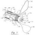
- FIG. 1is a perspective view of one embodiment of an anchoring device that is made in accordance with concepts of the present invention, the anchoring device being disposed on the distal end of an actuator device, and in a suture-unlocked position;
- FIG. 2is a cross-sectional, side, plan view of another embodiment of an anchoring device that is made in accordance with the concepts of the present invention, the anchoring device in a suture-unlocked position;
- FIG. 3is a cross-section, side, plan view of the embodiment of the anchoring device of FIG. 2 in a suture-locked position;
- FIG. 4is a top, plan view of yet another embodiment of an anchoring device that is made in accordance with the concepts of the present invention.
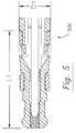
- FIG. 5is a cross-sectional, side, plan view of an anchoring device, like the anchoring devices of FIGS. 1-4 in a suture-unlocked position;
- FIG. 6is a cross-sectional, side, plan view of an anchoring device, like the anchoring devices of FIGS. 1-4 in a suture-locked position;
- FIG. 7is a perspective view of an embodiment of a system that is used to deploy an anchoring device such as the anchoring devices of FIGS. 1-6 .
- an anchoring deviceand system for deploying the same, embodiments of which are configured so that in its deployed state, the anchoring device displaces the cancellous layer of bone in a pre-formed hole, and engages the cortical layer of bone.
- Devicessuch as those disclosed and described herein include inner and outer members that are insertably engaged so as to permit relative movement of the members from a suture-unlocked position, to a suture-locked position. This secures suture material between the inner and outer members. It does not, however, cause the length of the suture material to change as the relative positions of the inner and outer member of the anchor are changed from the suture-unlocked position to the suture-locked position. Nor does it alter the axis of compression, so that tension that is applied to the suture material during the surgical procedure is maintained at a substantially consistent level when actuating the anchoring device from its suture-unlocked to suture-locked position in the bone.
- eachcan comprise biocompatible materials, which are sufficiently resilient, and which permit the relative movement of the inner and outer members. These materials may be of such composition that they are reabsorbed by the body, e.g., during the healing process of the bone.
- biocompatible materialswhich are sufficiently resilient, and which permit the relative movement of the inner and outer members. These materials may be of such composition that they are reabsorbed by the body, e.g., during the healing process of the bone.
- Exemplary materials that are suitable for use in the inner and outer membersinclude, but are not limited to, polyetheretherketone (“PEEK”), polylactic acid/beta-tricalcium phosphate (“PLA/Beta-TCP”) composites, ultra high molecular weight polyethylene (“UHMWPE”), as well as other metallic, non-metallic, and polymeric materials.
- PEEKpolyetheretherketone
- PLA/Beta-TCPpolylactic acid/beta-tricalcium phosphate
- UHMWPEultra high molecular weight polyethylene
- the materials that are selected for the inner and outer membersmay have physical properties that are consistent with, or compatible with certain performance factors for the anchoring device. These factors include, for example, tensile strength, shear strength, and flexibility of all or part of the anchoring device, as well as any combinations thereof. Each of the factors mentioned above, and contemplated herein may be determined in connection with the configuration of the inner and outer members, as well as in conjunction with the changes in the anchoring device as the relative positions of the inner and outer members change from the suture-unlocked position to the suture-locked position.
- the anchoring device 100comprises an outer member 102 , and an inner member 104 that is arranged in the present example relative to the outer member 102 in a suture-unlocked position.
- the outer member 102includes a substantially cylindrical body 106 that has an axial lumen 108 , which has an inner suture surface 110 , and a longitudinal axis 112 .
- the cylindrical body 106also includes an aperture 114 , and an outer member distal end 116 with an opening 118 that is sized and configured to receive the inner member 104 as described herein.
- the inner member 104comprises an elongated body 120 that has a distal portion 122 and a proximal portion 124 that extends away from the distal portion 122 .
- the distal portion 122includes an inner member distal end 126 with a distal lumen 128 , and an opening 130 that provides access to the distal lumen 128 .
- the distal portion 122also includes an outer suture surface 132 .
- the proximal portion 124includes a proximal end 134 with an outer dimension, and in the case of the elongated body 120 , the outer dimension is the diameter of the elongated body 120 as measured at the proximal end 134 .
- the proximal portion 124also includes an elongated projection 136 that extends from the distal portion 122 to the proximal end 134 .
- the elongated projection 136is constructed so as to cause the diameter of the proximal end 134 to change when the inner member 104 moves relative to the outer member 102 .
- the elongated projection 136is configured for radial movement away from the longitudinal axis 112 in response to the relative movement of the outer member 102 and the inner member 104 . This changes the outer dimension of the proximal end 134 . This can also cause the elongated projections 136 to engage the cancellous bone in the pre-formed hole, and in one construction of the inner member 104 the elongated projection 136 protrudes out of the aperture 114 so as to cause the proximal end 134 to engage the cortical layer of bone as the anchoring device 100 is deployed from the suture-unlocked position to the suture-locked position.
- the anchoring device 100 in the example of FIG. 1includes suture material 138 , which is positioned between the inner suture surface 110 and the outer suture surface 132 .
- the suture material 138includes loops 140 that are sized so as to engage other suture material, and/or soft tissue.
- the suture material 138is positioned in the anchoring device 100 during the surgical operation with one or more snares (not shown) that are positioned so that the suture material 138 is drawn into the anchoring device 100 , and more particularly between the outer member 102 and the inner member 104 .
- the suture material 138is pre-positioned in the anchoring device 100 so as to facilitate its deployment during the surgical procedure.
- the anchoring device 100is inserted into the pre-formed hole in the bone so that the loops 140 extend out of the hole and at a position to engage, e.g., the suture material, and/or the soft tissue.
- the inner member 104is moved relative to the outer member 102 along the longitudinal axis 112 . This compresses the suture material 138 between the inner suture surface 110 and the outer suture surface 132 .
- the anchoring device 200comprises an outer member 202 , and an inner member 204 that is positioned relative to the outer member 202 in a suture-unlocked position.
- the cylindrical body 206 of the outer member 202includes a pair of apertures 214 that each has a ramped portion 242 , which tapers substantially outwardly away from the longitudinal axis 212 .
- the apertures 214also have an aperture end surface 244 that is located on the side of the aperture 214 opposite the ramped portion 242 .
- the cylindrical body 206further includes an outer member proximal end 246 that has an end surface 248 , which is on the end of the cylindrical body 206 that is opposite of the outer member distal end 216 .
- the elongated body 220 of the inner member 204further comprises a distal portion 222 and a proximal portion 224 .
- the distal portion 222includes a distal lumen 230 that has a frangible portion 250 , which has a material disengagement area 252 that extends from the proximal portion 224 into the distal lumen 230 .
- the distal portion 222also includes an outer suture surface 232 that has a plurality of suture compression projections 254 with a projection surface 256 .
- the proximal portion 222includes a proximal end 234 , and a pair of elongated projections 236 , which extend from the proximal ends 234 to a step 258 that bounds the outer edge of the outer suture surface 232 .
- a secondary step 259is included that bounds the other edge of the outer suture surface 232 .
- Each of the elongated projections 236have an engagement surface 260 , which tapers substantially inwardly from the proximal end 234 toward the longitudinal axis 212 .
- the anchoring device 200is coupled to an actuator device 262 , and more particularly the actuator device 262 includes mating surface 264 in communication with the end surface 248 of the outer member.
- the actuator device 262also includes a mandrel 266 that is coupled to the material disengagement area 252 .
- this connectioncomprises one or more complimentary threaded surfaces on the material disengagement area 252 , and on the mandrel 266 .
- one or more of the material disengagement area 252 , and the mandrel 266can include a mechanical interface (not shown) that can engage a similar, or complimentary mechanical interface on the opposing part of the anchoring device 200 .
- suitable implements for use as the mechanical interfaceinclude, but are not limited to, a key-and-slot arrangement, shearable fasteners, adhesives, and tapes, among other devices, and methods for securing the material disengagement area 252 and the mandrel 266 .
- connection between the material disengagement area 252 , and the mandrel 266is configured to release, or “break away,” when a force applied by the actuator device 262 reaches and/or exceeds a threshold level.
- a force applied by the actuator device 262may shear the threaded surface of one or both of the material disengagement area 252 and the mandrel 264 .
- the threshold levelcan be determined in accordance with a number of factors (including materials of construction, the type or arrangement of the mechanical interface, etc.), the force is generally less than about 280 N, and in one example the force is from about 180 N to about 250 N.
- the material disengagement area 252 and the mandrel 266each have threaded surfaces with threads of about 80 threads per inch, and with about 0.8 mm to about 2 mm of threads that are engaged along the two threaded surfaces.
- the threshold levelmay be selected so as to permit the actuator device 262 to deploy the anchoring device 200 from the suture-unlocked position (of FIG. 2 ) to the suture-locked position (of FIG. 3 ), before the release of the connection between the material disengagement area 252 and the mandrel 266 .
- the actuator device 262can cause the inner member 202 to move in relation to the outer member 204 so as to cause the engagement surfaces 256 of the elongated projections 236 to engage the ramped portions 242 .
- the elongated projections 236urges the elongated projections 236 outwardly, and away from the longitudinal axis 212 , in a manner that changes the outer dimension of the proximal end 234 from a first dimension (in the suture-unlocked position) to a second dimension (in the suture-locked position).
- the difference between the first dimension and the second dimensionis from about 6 mm to about 9 mm.
- the anchoring device 200is maintained at this second dimension by the engagement of the outer member 202 and the inner member 204 .
- the step 258engages with the aperture end surfaces 244 .
- a portion of the outer member distal end 216engages the secondary step 259 , and the aperture end surface 244 engages the step 258 .
- the suture material(not shown) is compressed between the inner suture surface 210 , and one or more of the engagement surfaces 256 .
- Each of the inner suture surface 210 and the engagement surfaces 256can have, respectively, an inner diameter and an outer diameter that is dependent on the amount of compression of the suture material, as a percentage of the diameter of the suture material. This is typically dependent upon the suture material, but is estimated to be on the order of from about 70% to about 80%, and may in some embodiments be from about 50% to about 90%.
- the amount of suture material that is compressed between the inner suture surface 210 and the engagement surfaces 256also considered the length of the compressed suture material, is generally less than about 4 mm, and more typically from about 2 mm to about 3 mm.
- the dimensions and the tolerances of the outer member 202 and the inner member 204 in many embodiments of the present inventionare such that as the inner member 204 moves relative to the outer member 202 , they may deform out of concentricity when the suture material is compressed only at two diametrically opposed locations.
- the locationsare spaced at about 90° from the position of the suture material, e.g., the position of the projections 236 on the inner member 204 , and generally not subject to the same stresses and may not be deformed to the same extent.
- the extent of the deformationis well within the degree of resilience of the materials of construction contemplated and discussed herein.
- FIG. 4illustrates another embodiment of an anchoring device 400 that is made in accordance with the present invention.
- the anchoring device 400includes a longitudinal axis 412 , as well as an aperture 414 , and an elongated projection 436 . Both the aperture 414 and the elongated projection 436 are located an offset distance (h) from the longitudinal axis 412 .
- the position of the aperture 414is determined in accordance with the general dimensions (e.g., first offset dimension (h 1 ), and second offset dimension (h 2 )) of the elongated projection 436 .
- the offset distance (h), as well as the first offset dimension (h 1 ), and the second offset dimension h 2can be employed on any of the embodiments of the anchoring device 100 , 200 , 400 disclosed and discussed herein.
- the offset distance (h)is provided in the anchoring device 400 so as to provide only one loop 440 of the suture material 438 .
- FIGS. 5 and 6illustrate examples of an anchoring device in a suture-unlocked position 500 , and a suture-locked position 600 . It is seen in FIG. 5 that the length (L 1 ) of the anchoring devices in the suture-unlocked position 500 is from about 12 mm to about 17 mm. It is seen in FIG. 5
- the length (L 2 ) of the anchoring device in the suture-locked position 600is from about 9 mm to about 11 mm
- the elongated projectionsmay have a length (L 3 ) from about 4 mm to about 10 mm, with a portion of the elongated projections having a length (L 4 ) from about 2 mm to about 5 mm.
- the unemployed diameter (D 1 ), the “first dimension,” at the proximal end of the anchoring deviceis from about 4 mm to 6 mm
- the deployed diameter (D 2 ), the “second dimension,”is from about 6 mm to about 9 mm
- the diameter (D 3 ) of the outer member at the distal endis from about 3 mm to about 5 mm
- the diameter (D 4 ) of the inner member at the distal endis from about 2 mm to about 4 mm. All of these dimensions, however, are provided as non-limiting examples and is not meant to limit the scope, content, or concepts of the present disclosure. That is, certain ones of the dimensions discussed immediately above, when applied to other embodiments the anchoring devices, may change with respect to other dimension, pieces, and aspects of the present invention.
- FIG. 7illustrates an example of a system 700 that is used to deploy the anchoring devices disclosed herein.
- an anchoring device 702is situated on an actuator device 704 that has a distal end 706 , and a proximal end 708 . More particularly, the anchoring device 702 is positioned on the distal end 706 so as to engage a mandrel (not shown).
- the actuator device 704further includes a handle 710 and an elongated shaft 712 that houses the mandrel therein.
- Actuator device 704comprises a trigger 714 , and a drive mechanism (not shown) that is attached to the proximal end 708 of the elongated shaft 712 .
- the drive mechanismmay include levers, pivots, rollers, joints, and other mechanisms that are arranged together to provide longitudinal movement of the mandrel (not shown), and thus cause the relative movement of the parts of the anchoring device (e.g., the inner and outer members) as discussed in detail above.
- the actuator device 704may include the trigger 714 and a pivot 716 that couples the trigger 714 to the drive mechanism (not shown).
- the actuator device 704may also include a detent 718 that engages the trigger 714 in a manner that prevents premature actuation of the device.
- the detent 718extends from part of the handle 710 into the trigger 714 a distance, which is selected based on an amount of force desired to fully engage the trigger 714 and deploy the anchoring device.
- depressing the trigger 714exerts a proximally directed force that causes the relative movement of the inner member with respect to the outer member.
- the drive mechanismis configured to pull the inner member toward the handle 710 with the mandrel. This, in turn, causes the elongated projections to expand into the cancellous bone, and in one particular embodiment causes the mandrel to frangibly disconnect from the inner member based on a threshold force.
Landscapes
- Health & Medical Sciences (AREA)
- Surgery (AREA)
- Life Sciences & Earth Sciences (AREA)
- Biomedical Technology (AREA)
- Nuclear Medicine, Radiotherapy & Molecular Imaging (AREA)
- Engineering & Computer Science (AREA)
- Rheumatology (AREA)
- Heart & Thoracic Surgery (AREA)
- Medical Informatics (AREA)
- Molecular Biology (AREA)
- Animal Behavior & Ethology (AREA)
- General Health & Medical Sciences (AREA)
- Public Health (AREA)
- Veterinary Medicine (AREA)
- Surgical Instruments (AREA)
Abstract
Description
Claims (18)
Priority Applications (1)
| Application Number | Priority Date | Filing Date | Title |
|---|---|---|---|
| US12/487,280US8409252B2 (en) | 2008-03-25 | 2009-06-18 | Knotless suture anchor |
Applications Claiming Priority (2)
| Application Number | Priority Date | Filing Date | Title |
|---|---|---|---|
| US12/079,097US8162978B2 (en) | 2008-03-25 | 2008-03-25 | Non-metallic knotless suture anchor |
| US12/487,280US8409252B2 (en) | 2008-03-25 | 2009-06-18 | Knotless suture anchor |
Related Parent Applications (1)
| Application Number | Title | Priority Date | Filing Date |
|---|---|---|---|
| US12/079,097Continuation-In-PartUS8162978B2 (en) | 2008-03-25 | 2008-03-25 | Non-metallic knotless suture anchor |
Publications (2)
| Publication Number | Publication Date |
|---|---|
| US20090318964A1 US20090318964A1 (en) | 2009-12-24 |
| US8409252B2true US8409252B2 (en) | 2013-04-02 |
Family
ID=41431993
Family Applications (1)
| Application Number | Title | Priority Date | Filing Date |
|---|---|---|---|
| US12/487,280Active2029-10-19US8409252B2 (en) | 2008-03-25 | 2009-06-18 | Knotless suture anchor |
Country Status (1)
| Country | Link |
|---|---|
| US (1) | US8409252B2 (en) |
Cited By (31)
| Publication number | Priority date | Publication date | Assignee | Title |
|---|---|---|---|---|
| US20130158597A1 (en)* | 2011-12-19 | 2013-06-20 | Depuy Mitek, Inc. | Knotless Suture Anchor |
| US8951268B2 (en)* | 2010-05-17 | 2015-02-10 | I.B.I. Israel Biomedical Innovations Ltd. | Surgical fastening device with mesh retaining means |
| US9101355B2 (en) | 2009-07-17 | 2015-08-11 | Pivot Medical, Inc. | Method and apparatus for re-attaching the labrum to the acetabulum, including the provision and use of a novel suture anchor system |
| US9149268B2 (en) | 2009-07-17 | 2015-10-06 | Pivot Medical, Inc. | Method and apparatus for attaching tissue to bone, including the provision and use of a novel knotless suture anchor system |
| US9179905B2 (en) | 2009-07-17 | 2015-11-10 | Pivot Medical, Inc. | Method and apparatus for re-attaching the labrum to the acetabulum, including the provision and use of a novel suture anchor system |
| US9414834B2 (en)* | 2013-03-08 | 2016-08-16 | Biomet Sports Medicine, Llc | Knotless suture anchor and method of using same |
| WO2017106608A2 (en) | 2015-12-16 | 2017-06-22 | Conmed Corporation | Knotless suture anchor and deployment device |
| US9826973B2 (en) | 2009-07-17 | 2017-11-28 | Pivot Medical, Inc. | Method and apparatus for attaching tissue to bone, including the provision and use of a novel knotless suture anchor system |
| CN107454833A (en)* | 2015-03-25 | 2017-12-08 | 泰耶·艾德 | Device for introducing a port into an umbilical vessel and maintaining the port in the umbilical vessel |
| WO2018035232A1 (en) | 2016-08-16 | 2018-02-22 | Conmed Corporation | Device for securing suture to an anchor body of a suture anchor |
| US10058319B2 (en) | 2009-07-17 | 2018-08-28 | Pivot Medical, Inc. | Method and apparatus for attaching tissue to bone, including the provision and use of a novel knotless suture anchor system, including a novel locking element |
| US10136884B2 (en) | 2009-07-17 | 2018-11-27 | Pivot Medical, Inc. | Method and apparatus for attaching tissue to bone, including the provision and use of a novel knotless suture anchor system, including a retractable sheath |
| WO2018226663A1 (en) | 2017-06-05 | 2018-12-13 | Conmed Corporation | Multi-barrel drill guide and anchor deployment assembly |
| WO2018226490A1 (en) | 2017-06-05 | 2018-12-13 | Conmed Corporation | Multi-barrel drill guide |
| WO2019023205A1 (en) | 2017-07-24 | 2019-01-31 | Conmed Corporation | Self-drilling all-suture anchor inserter |
| WO2019032797A1 (en) | 2017-08-10 | 2019-02-14 | Conmed Corporation | Hybrid suture anchor |
| US10238379B2 (en) | 2009-07-17 | 2019-03-26 | Pivot Medical, Inc. | Method and apparatus for attaching tissue to bone, including the provision and use of a novel knotless suture anchor system |
| US10292696B2 (en) | 2012-08-03 | 2019-05-21 | Stabilynx, Inc. | Devices, systems, and methods for attaching soft tissue to bone tissue |
| US10292694B2 (en) | 2013-04-22 | 2019-05-21 | Pivot Medical, Inc. | Method and apparatus for attaching tissue to bone |
| WO2019118681A1 (en) | 2017-12-13 | 2019-06-20 | Conmed Corporation | Multi-density all suture anchor |
| WO2019182645A1 (en) | 2018-03-23 | 2019-09-26 | Conmed Corporation | Suture anchor driver |
| US10426456B2 (en) | 2009-07-17 | 2019-10-01 | Pivot Medical, Inc. | Method and apparatus for re-attaching the labrum to the acetabulum, including the provision and use of a novel suture anchor system |
| WO2020132049A2 (en) | 2018-12-18 | 2020-06-25 | Conmed Corporation | Self-drilling anchor inserter |
| KR102180896B1 (en) | 2020-01-07 | 2020-11-19 | 주식회사 에이알씨코리아 | Suture anchor deployment device |
| WO2021150257A1 (en) | 2020-01-20 | 2021-07-29 | Conmed Corporation | Self-drilling anchor inserter |
| US11197663B2 (en) | 2009-07-17 | 2021-12-14 | Stryker Puerto Rico Limited | Method and apparatus for attaching tissue to bone, including the provision and use of a novel knotless suture anchor system |
| US11246585B2 (en) | 2009-07-17 | 2022-02-15 | Stryker Puerto Rico Limited | Method and apparatus for attaching tissue to bone, including the provision and use of a novel knotless suture anchor system |
| US11298120B2 (en) | 2018-09-11 | 2022-04-12 | Responsive Arthroscopy, LLC | Wedge push-in suture anchor |
| US11510665B2 (en) | 2020-03-30 | 2022-11-29 | Responsive Arthroscopy, LLC | Suture based clamping device |
| US12161318B2 (en) | 2020-12-01 | 2024-12-10 | Dunamis Medical Technologies, Llc | Re-tensionable suture anchor system and related methods |
| US12232718B2 (en) | 2009-07-17 | 2025-02-25 | Stryker Puerto Rico Limited | Method and apparatus for attaching tissue to bone, including the provision and use of a novel knotless suture anchor system |
Families Citing this family (18)
| Publication number | Priority date | Publication date | Assignee | Title |
|---|---|---|---|---|
| US6319252B1 (en) | 1999-07-23 | 2001-11-20 | Mcdevitt Dennis | System and method for attaching soft tissue to bone |
| US6527794B1 (en) | 1999-08-10 | 2003-03-04 | Ethicon, Inc. | Self-locking suture anchor |
| US6733506B1 (en) | 2000-11-16 | 2004-05-11 | Ethicon, Inc. | Apparatus and method for attaching soft tissue to bone |
| US9788825B2 (en) | 2006-08-04 | 2017-10-17 | Depuy Mitek, Llc | Suture anchor with relief mechanism |
| US9750492B2 (en) | 2006-08-04 | 2017-09-05 | Depuy Mitek, Llc | Suture anchor system with tension relief mechanism |
| US8449612B2 (en)* | 2009-11-16 | 2013-05-28 | Arthrocare Corporation | Graft pulley and methods of use |
| US8435264B2 (en) | 2010-08-30 | 2013-05-07 | Depuy Mitek, Llc | Knotless suture anchor and driver |
| US8469998B2 (en) | 2010-08-30 | 2013-06-25 | Depuy Mitek, Llc | Knotless suture anchor |
| US8679159B2 (en) | 2010-08-30 | 2014-03-25 | Depuy Mitek, Llc | Anchor driver with suture clutch |
| US8460340B2 (en) | 2010-08-30 | 2013-06-11 | Depuy Mitek, Llc | Knotless suture anchor |
| WO2012109453A1 (en)* | 2011-02-09 | 2012-08-16 | Allegheny-Singer Research Institute | Method and devise for tendon repair |
| US12390258B2 (en) | 2012-07-18 | 2025-08-19 | Jmea Corporation | Methods and apparatus for implanting prostheses |
| US9198704B2 (en) | 2012-07-18 | 2015-12-01 | Jmea Corporation | Impact and drive system for prosthesis deployment device |
| WO2015005951A1 (en)* | 2013-07-10 | 2015-01-15 | Smith & Nephew, Inc. | Distal tip two piece external expansion anchor |
| RU2016138851A (en)* | 2014-03-06 | 2018-04-09 | Смит Энд Нефью, Инк. | TWO-SECTION UNIT-NODE SUSTER MATCH |
| FR3021864B1 (en)* | 2014-06-06 | 2019-10-25 | In2Bones | SURGICAL IMPLANT, IMPLEMENT TOOL, SURGICAL KIT AND METHOD FOR MANUFACTURING THE SAME |
| WO2016160445A1 (en)* | 2015-03-23 | 2016-10-06 | Conmed Corporation | Securing graft tissue in a bone tunnel and implementations thereof |
| US12232950B2 (en)* | 2020-11-02 | 2025-02-25 | Acumed Llc | Bone anchor insertion system having inserter coupling and decoupling |
Citations (15)
| Publication number | Priority date | Publication date | Assignee | Title |
|---|---|---|---|---|
| US5643321A (en)* | 1994-11-10 | 1997-07-01 | Innovasive Devices | Suture anchor assembly and methods |
| US5702215A (en)* | 1995-06-05 | 1997-12-30 | Li Medical Technologies, Inc. | Retractable fixation device |
| US5843127A (en)* | 1994-08-22 | 1998-12-01 | Le Medical Technologies, Inc. | Fixation device and method for installing same |
| US5849004A (en)* | 1996-07-17 | 1998-12-15 | Bramlet; Dale G. | Surgical anchor |
| US5935129A (en)* | 1997-03-07 | 1999-08-10 | Innovasive Devices, Inc. | Methods and apparatus for anchoring objects to bone |
| US6022373A (en)* | 1996-09-10 | 2000-02-08 | Li Medical Technologies, Inc. | Surgical anchor and package and cartridge for surgical anchor |
| US6527794B1 (en)* | 1999-08-10 | 2003-03-04 | Ethicon, Inc. | Self-locking suture anchor |
| US6692516B2 (en)* | 2000-11-28 | 2004-02-17 | Linvatec Corporation | Knotless suture anchor and method for knotlessly securing tissue |
| US6695844B2 (en)* | 1996-03-13 | 2004-02-24 | Orthopedic Designs, Inc. | Surgical fastener assembly |
| US6932834B2 (en)* | 2002-06-27 | 2005-08-23 | Ethicon, Inc. | Suture anchor |
| US20060116719A1 (en)* | 2000-09-15 | 2006-06-01 | Jonathan Martinek | Knotless tissue anchor |
| US20060235413A1 (en)* | 2004-12-07 | 2006-10-19 | Arthrotek, Inc. | Expanding suture anchor having an actuator pin |
| US20070093858A1 (en)* | 2000-03-03 | 2007-04-26 | C. R. Bard, Inc. | Suture clips, delivery devices and methods |
| US20070270907A1 (en)* | 2006-05-19 | 2007-11-22 | Stokes Michael J | Suture locking device |
| US7837710B2 (en)* | 2003-09-10 | 2010-11-23 | Linvatec Corporation | Knotless suture anchor |
- 2009
- 2009-06-18USUS12/487,280patent/US8409252B2/enactiveActive
Patent Citations (16)
| Publication number | Priority date | Publication date | Assignee | Title |
|---|---|---|---|---|
| US5843127A (en)* | 1994-08-22 | 1998-12-01 | Le Medical Technologies, Inc. | Fixation device and method for installing same |
| US5643321A (en)* | 1994-11-10 | 1997-07-01 | Innovasive Devices | Suture anchor assembly and methods |
| US5702215A (en)* | 1995-06-05 | 1997-12-30 | Li Medical Technologies, Inc. | Retractable fixation device |
| US6695844B2 (en)* | 1996-03-13 | 2004-02-24 | Orthopedic Designs, Inc. | Surgical fastener assembly |
| US5849004A (en)* | 1996-07-17 | 1998-12-15 | Bramlet; Dale G. | Surgical anchor |
| US6022373A (en)* | 1996-09-10 | 2000-02-08 | Li Medical Technologies, Inc. | Surgical anchor and package and cartridge for surgical anchor |
| US5935129A (en)* | 1997-03-07 | 1999-08-10 | Innovasive Devices, Inc. | Methods and apparatus for anchoring objects to bone |
| US6527794B1 (en)* | 1999-08-10 | 2003-03-04 | Ethicon, Inc. | Self-locking suture anchor |
| US20090099598A1 (en)* | 1999-08-10 | 2009-04-16 | Depuy Mitek, Inc. | Self-locking suture anchor |
| US20070093858A1 (en)* | 2000-03-03 | 2007-04-26 | C. R. Bard, Inc. | Suture clips, delivery devices and methods |
| US20060116719A1 (en)* | 2000-09-15 | 2006-06-01 | Jonathan Martinek | Knotless tissue anchor |
| US6692516B2 (en)* | 2000-11-28 | 2004-02-17 | Linvatec Corporation | Knotless suture anchor and method for knotlessly securing tissue |
| US6932834B2 (en)* | 2002-06-27 | 2005-08-23 | Ethicon, Inc. | Suture anchor |
| US7837710B2 (en)* | 2003-09-10 | 2010-11-23 | Linvatec Corporation | Knotless suture anchor |
| US20060235413A1 (en)* | 2004-12-07 | 2006-10-19 | Arthrotek, Inc. | Expanding suture anchor having an actuator pin |
| US20070270907A1 (en)* | 2006-05-19 | 2007-11-22 | Stokes Michael J | Suture locking device |
Cited By (48)
| Publication number | Priority date | Publication date | Assignee | Title |
|---|---|---|---|---|
| US10426456B2 (en) | 2009-07-17 | 2019-10-01 | Pivot Medical, Inc. | Method and apparatus for re-attaching the labrum to the acetabulum, including the provision and use of a novel suture anchor system |
| US11197663B2 (en) | 2009-07-17 | 2021-12-14 | Stryker Puerto Rico Limited | Method and apparatus for attaching tissue to bone, including the provision and use of a novel knotless suture anchor system |
| US9101355B2 (en) | 2009-07-17 | 2015-08-11 | Pivot Medical, Inc. | Method and apparatus for re-attaching the labrum to the acetabulum, including the provision and use of a novel suture anchor system |
| US10363025B2 (en) | 2009-07-17 | 2019-07-30 | Pivot Medical, Inc. | Method and apparatus for re-attaching the labrum to the acetabulum, including the provision and use of a novel suture anchor system |
| US9149268B2 (en) | 2009-07-17 | 2015-10-06 | Pivot Medical, Inc. | Method and apparatus for attaching tissue to bone, including the provision and use of a novel knotless suture anchor system |
| US9179905B2 (en) | 2009-07-17 | 2015-11-10 | Pivot Medical, Inc. | Method and apparatus for re-attaching the labrum to the acetabulum, including the provision and use of a novel suture anchor system |
| US11517300B2 (en) | 2009-07-17 | 2022-12-06 | Stryker Puerto Rico, LLC | Method and apparatus for re-attaching the labrum to the acetabulum, including the provision and use of a novel suture anchor system |
| US9451943B2 (en) | 2009-07-17 | 2016-09-27 | Pivoc Medical, Inc. | Method and apparatus for re-attaching the labrum to the acetabulum, including the provision and use of a novel suture anchor system |
| US11246585B2 (en) | 2009-07-17 | 2022-02-15 | Stryker Puerto Rico Limited | Method and apparatus for attaching tissue to bone, including the provision and use of a novel knotless suture anchor system |
| US9826973B2 (en) | 2009-07-17 | 2017-11-28 | Pivot Medical, Inc. | Method and apparatus for attaching tissue to bone, including the provision and use of a novel knotless suture anchor system |
| US12232718B2 (en) | 2009-07-17 | 2025-02-25 | Stryker Puerto Rico Limited | Method and apparatus for attaching tissue to bone, including the provision and use of a novel knotless suture anchor system |
| US10238379B2 (en) | 2009-07-17 | 2019-03-26 | Pivot Medical, Inc. | Method and apparatus for attaching tissue to bone, including the provision and use of a novel knotless suture anchor system |
| US10058319B2 (en) | 2009-07-17 | 2018-08-28 | Pivot Medical, Inc. | Method and apparatus for attaching tissue to bone, including the provision and use of a novel knotless suture anchor system, including a novel locking element |
| US10092285B2 (en) | 2009-07-17 | 2018-10-09 | Pivot Medical, Inc. | Method and apparatus for attaching tissue to bone, including the provision and use of a novel knotless suture anchor system |
| US10123793B2 (en) | 2009-07-17 | 2018-11-13 | Pivot Medical, Inc. | Method and apparatus for re-attaching the labrum to the acetabulum including the provision and use of a novel suture anchor system |
| US10136884B2 (en) | 2009-07-17 | 2018-11-27 | Pivot Medical, Inc. | Method and apparatus for attaching tissue to bone, including the provision and use of a novel knotless suture anchor system, including a retractable sheath |
| US8951268B2 (en)* | 2010-05-17 | 2015-02-10 | I.B.I. Israel Biomedical Innovations Ltd. | Surgical fastening device with mesh retaining means |
| US20130158597A1 (en)* | 2011-12-19 | 2013-06-20 | Depuy Mitek, Inc. | Knotless Suture Anchor |
| US10881389B2 (en) | 2011-12-19 | 2021-01-05 | Medos International Sarl | Knotless suture anchor |
| US9138220B2 (en)* | 2011-12-19 | 2015-09-22 | Medos International Sarl | Knotless suture anchor |
| US10595853B2 (en) | 2012-08-03 | 2020-03-24 | Stabilynx, Inc. | Devices, systems, and methods for attaching soft tissue to bone tissue |
| US11504111B2 (en) | 2012-08-03 | 2022-11-22 | Stabilynx, Inc. | Devices, systems, and methods for attaching soft tissue to bone tissue |
| US10292696B2 (en) | 2012-08-03 | 2019-05-21 | Stabilynx, Inc. | Devices, systems, and methods for attaching soft tissue to bone tissue |
| US10201344B2 (en) | 2013-03-08 | 2019-02-12 | Biomet Sports Medicine, Llc | Knotless suture anchor and method of using same |
| US9414834B2 (en)* | 2013-03-08 | 2016-08-16 | Biomet Sports Medicine, Llc | Knotless suture anchor and method of using same |
| US11331094B2 (en) | 2013-04-22 | 2022-05-17 | Stryker Corporation | Method and apparatus for attaching tissue to bone |
| US12048427B2 (en) | 2013-04-22 | 2024-07-30 | Stryker Corporation | Method and apparatus for attaching tissue to bone |
| US10292694B2 (en) | 2013-04-22 | 2019-05-21 | Pivot Medical, Inc. | Method and apparatus for attaching tissue to bone |
| CN107454833A (en)* | 2015-03-25 | 2017-12-08 | 泰耶·艾德 | Device for introducing a port into an umbilical vessel and maintaining the port in the umbilical vessel |
| WO2017106608A2 (en) | 2015-12-16 | 2017-06-22 | Conmed Corporation | Knotless suture anchor and deployment device |
| EP3753496A1 (en) | 2015-12-16 | 2020-12-23 | ConMed Corporation | Knotless suture anchor and deployment device |
| WO2018035232A1 (en) | 2016-08-16 | 2018-02-22 | Conmed Corporation | Device for securing suture to an anchor body of a suture anchor |
| EP4371506A2 (en) | 2017-06-05 | 2024-05-22 | CONMED Corporation | Multi-barrel drill guide and anchor deployment assembly |
| EP4368126A2 (en) | 2017-06-05 | 2024-05-15 | ConMed Corporation | Multi-barrel drill guide |
| WO2018226663A1 (en) | 2017-06-05 | 2018-12-13 | Conmed Corporation | Multi-barrel drill guide and anchor deployment assembly |
| WO2018226490A1 (en) | 2017-06-05 | 2018-12-13 | Conmed Corporation | Multi-barrel drill guide |
| WO2019023205A1 (en) | 2017-07-24 | 2019-01-31 | Conmed Corporation | Self-drilling all-suture anchor inserter |
| WO2019032797A1 (en) | 2017-08-10 | 2019-02-14 | Conmed Corporation | Hybrid suture anchor |
| WO2019118681A1 (en) | 2017-12-13 | 2019-06-20 | Conmed Corporation | Multi-density all suture anchor |
| EP4464259A2 (en) | 2017-12-13 | 2024-11-20 | Conmed Corporation | Multy-density all suture anchor |
| WO2019182645A1 (en) | 2018-03-23 | 2019-09-26 | Conmed Corporation | Suture anchor driver |
| US11298120B2 (en) | 2018-09-11 | 2022-04-12 | Responsive Arthroscopy, LLC | Wedge push-in suture anchor |
| WO2020132049A2 (en) | 2018-12-18 | 2020-06-25 | Conmed Corporation | Self-drilling anchor inserter |
| KR102180896B1 (en) | 2020-01-07 | 2020-11-19 | 주식회사 에이알씨코리아 | Suture anchor deployment device |
| WO2021150257A1 (en) | 2020-01-20 | 2021-07-29 | Conmed Corporation | Self-drilling anchor inserter |
| US11510665B2 (en) | 2020-03-30 | 2022-11-29 | Responsive Arthroscopy, LLC | Suture based clamping device |
| US12178425B2 (en) | 2020-03-30 | 2024-12-31 | Responsive Arthroscopy, LLC | Suture based clamping device |
| US12161318B2 (en) | 2020-12-01 | 2024-12-10 | Dunamis Medical Technologies, Llc | Re-tensionable suture anchor system and related methods |
Also Published As
| Publication number | Publication date |
|---|---|
| US20090318964A1 (en) | 2009-12-24 |
Similar Documents
| Publication | Publication Date | Title |
|---|---|---|
| US8409252B2 (en) | Knotless suture anchor | |
| US8162978B2 (en) | Non-metallic knotless suture anchor | |
| US20110224726A1 (en) | Suture anchor | |
| CN102525583B (en) | Adjustable anchor system and method | |
| US9414834B2 (en) | Knotless suture anchor and method of using same | |
| EP3490467B1 (en) | Suture securing assemblies | |
| US7837710B2 (en) | Knotless suture anchor | |
| EP2662032B1 (en) | Systems and devices for securing tissue | |
| AU2017313744B2 (en) | Device for securing suture to an anchor body of a suture anchor | |
| WO2009112930A2 (en) | Medical closure device | |
| CN114931408A (en) | Apparatus and method for repairing tissue | |
| US9924935B2 (en) | Suture anchor assembly with slip fit tip | |
| US20240197311A1 (en) | All-Suture Anchor | |
| KR20180048965A (en) | End effector for lesion sealing device | |
| US12011155B2 (en) | Double row collapsible suture construct | |
| US20240148375A1 (en) | Suture construct | |
| US20090210005A1 (en) | Method and system for displacing hyoid bone |
Legal Events
| Date | Code | Title | Description |
|---|---|---|---|
| AS | Assignment | Owner name:LINVATEC CORPORATION, FLORIDA Free format text:ASSIGNMENT OF ASSIGNORS INTEREST;ASSIGNORS:LOMBARDO, GIUSEPPE;FITTS, STEVEN E.;REEL/FRAME:023200/0588;SIGNING DATES FROM 20090720 TO 20090721 Owner name:LINVATEC CORPORATION, FLORIDA Free format text:ASSIGNMENT OF ASSIGNORS INTEREST;ASSIGNORS:LOMBARDO, GIUSEPPE;FITTS, STEVEN E.;SIGNING DATES FROM 20090720 TO 20090721;REEL/FRAME:023200/0588 | |
| STCF | Information on status: patent grant | Free format text:PATENTED CASE | |
| FPAY | Fee payment | Year of fee payment:4 | |
| FEPP | Fee payment procedure | Free format text:MAINTENANCE FEE REMINDER MAILED (ORIGINAL EVENT CODE: REM.); ENTITY STATUS OF PATENT OWNER: LARGE ENTITY | |
| FEPP | Fee payment procedure | Free format text:7.5 YR SURCHARGE - LATE PMT W/IN 6 MO, LARGE ENTITY (ORIGINAL EVENT CODE: M1555); ENTITY STATUS OF PATENT OWNER: LARGE ENTITY | |
| MAFP | Maintenance fee payment | Free format text:PAYMENT OF MAINTENANCE FEE, 8TH YEAR, LARGE ENTITY (ORIGINAL EVENT CODE: M1552); ENTITY STATUS OF PATENT OWNER: LARGE ENTITY Year of fee payment:8 | |
| MAFP | Maintenance fee payment | Free format text:PAYMENT OF MAINTENANCE FEE, 12TH YEAR, LARGE ENTITY (ORIGINAL EVENT CODE: M1553); ENTITY STATUS OF PATENT OWNER: LARGE ENTITY Year of fee payment:12 | |
| AS | Assignment | Owner name:JPMORGAN CHASE BANK, N.A., AS ADMINISTRATIVE AGENT, ILLINOIS Free format text:SECURITY INTEREST;ASSIGNORS:CONMED CORPORATION;BIOREZ, INC.;BUFFALO FILTER LLC;AND OTHERS;REEL/FRAME:072097/0762 Effective date:20250610 |