US8409245B2 - Surgical instrument - Google Patents
Surgical instrumentDownload PDFInfo
- Publication number
- US8409245B2 US8409245B2US11/805,420US80542007AUS8409245B2US 8409245 B2US8409245 B2US 8409245B2US 80542007 AUS80542007 AUS 80542007AUS 8409245 B2US8409245 B2US 8409245B2
- Authority
- US
- United States
- Prior art keywords
- proximal
- instrument
- distal
- handle
- bendable
- Prior art date
- Legal status (The legal status is an assumption and is not a legal conclusion. Google has not performed a legal analysis and makes no representation as to the accuracy of the status listed.)
- Active, expires
Links
- 230000007246mechanismEffects0.000claimsabstractdescription84
- 230000000452restraining effectEffects0.000claimsdescription15
- 230000008878couplingEffects0.000abstractdescription6
- 238000010168coupling processMethods0.000abstractdescription6
- 238000005859coupling reactionMethods0.000abstractdescription6
- 238000005452bendingMethods0.000description32
- 230000009471actionEffects0.000description20
- 239000012636effectorSubstances0.000description19
- 238000000034methodMethods0.000description16
- 238000010276constructionMethods0.000description7
- 238000001356surgical procedureMethods0.000description6
- 239000003351stiffenerSubstances0.000description4
- 238000003780insertionMethods0.000description3
- 230000037431insertionEffects0.000description3
- 238000002324minimally invasive surgeryMethods0.000description3
- 230000007704transitionEffects0.000description3
- 229920002614Polyether block amidePolymers0.000description2
- 210000003484anatomyAnatomy0.000description2
- 239000012141concentrateSubstances0.000description2
- 230000000994depressogenic effectEffects0.000description2
- 239000000463materialSubstances0.000description2
- 239000004033plasticSubstances0.000description2
- 230000004044responseEffects0.000description2
- 238000005096rolling processMethods0.000description2
- 210000003815abdominal wallAnatomy0.000description1
- 210000001124body fluidAnatomy0.000description1
- 230000000747cardiac effectEffects0.000description1
- 230000008859changeEffects0.000description1
- 230000006835compressionEffects0.000description1
- 238000007906compressionMethods0.000description1
- 238000005520cutting processMethods0.000description1
- 230000007812deficiencyEffects0.000description1
- 238000006073displacement reactionMethods0.000description1
- 238000002224dissectionMethods0.000description1
- 230000000694effectsEffects0.000description1
- 239000013013elastic materialSubstances0.000description1
- 239000000945fillerSubstances0.000description1
- 239000012530fluidSubstances0.000description1
- 230000002262irrigationEffects0.000description1
- 238000003973irrigationMethods0.000description1
- 238000002357laparoscopic surgeryMethods0.000description1
- 238000004519manufacturing processMethods0.000description1
- 239000007769metal materialSubstances0.000description1
- 238000012986modificationMethods0.000description1
- 230000004048modificationEffects0.000description1
- 230000000399orthopedic effectEffects0.000description1
- 229920000642polymerPolymers0.000description1
- 210000002307prostateAnatomy0.000description1
- 230000001681protective effectEffects0.000description1
- 239000012858resilient materialSubstances0.000description1
- 239000000523sampleSubstances0.000description1
- 125000006850spacer groupChemical group0.000description1
- 230000001225therapeutic effectEffects0.000description1
Images


Classifications
- A—HUMAN NECESSITIES
- A61—MEDICAL OR VETERINARY SCIENCE; HYGIENE
- A61B—DIAGNOSIS; SURGERY; IDENTIFICATION
- A61B17/00—Surgical instruments, devices or methods
- A61B17/00234—Surgical instruments, devices or methods for minimally invasive surgery
- A—HUMAN NECESSITIES
- A61—MEDICAL OR VETERINARY SCIENCE; HYGIENE
- A61B—DIAGNOSIS; SURGERY; IDENTIFICATION
- A61B17/00—Surgical instruments, devices or methods
- A61B17/28—Surgical forceps
- A61B17/29—Forceps for use in minimally invasive surgery
- A—HUMAN NECESSITIES
- A61—MEDICAL OR VETERINARY SCIENCE; HYGIENE
- A61B—DIAGNOSIS; SURGERY; IDENTIFICATION
- A61B17/00—Surgical instruments, devices or methods
- A61B17/00234—Surgical instruments, devices or methods for minimally invasive surgery
- A61B2017/00292—Surgical instruments, devices or methods for minimally invasive surgery mounted on or guided by flexible, e.g. catheter-like, means
- A61B2017/003—Steerable
- A—HUMAN NECESSITIES
- A61—MEDICAL OR VETERINARY SCIENCE; HYGIENE
- A61B—DIAGNOSIS; SURGERY; IDENTIFICATION
- A61B17/00—Surgical instruments, devices or methods
- A61B17/28—Surgical forceps
- A61B17/29—Forceps for use in minimally invasive surgery
- A61B2017/2901—Details of shaft
- A61B2017/2905—Details of shaft flexible
Definitions
- the present inventionrelates in general to medical instruments, and more particularly to manually-operated surgical instruments that are intended for use in minimally invasive surgery or other forms of surgical or medical procedures or techniques.
- the instrument described hereinis primarily for a laparoscopic procedure, however, it is to be understood that the instrument of the present invention can be used for a wide variety of other procedures, including intraluminal procedures.
- Endoscopic and laparoscopic instruments currently available in the marketare extremely difficult to learn to operate and use, mainly due to a lack of dexterity in their use.
- the orientation of the tool of the instrumentis solely dictated by the location of the target and the incision.
- These instrumentsgenerally function with a fulcrum effect using the patients own incision area as the fulcrum.
- common taskssuch as suturing, knotting and fine dissection have become challenging to master.
- Various laparoscopic instrumentshave been developed over the years to overcome this deficiency, usually by providing an extra articulation often controlled by a separately disposed control member for added control.
- an object of the present inventionis to provide an improved laparoscopic or endoscopic surgical instrument that allows the surgeon to manipulate the tool end of the surgical instrument with greater dexterity.
- Another object of the present inventionis to provide an improved surgical or medical instrument that has a wide variety of applications, through incisions, through natural body orifices or intraluminally.
- a further object of the present inventionis to provide an improved medical instrument in which the proximal portion of the instrument can be re-positioned while the distal portion of the instrument is maintained in a predetermined position.
- Another object of the present inventionis to provide a locking feature that is an important adjunct to the other controls of the instrument enabling the surgeon to lock the instrument once in the desired position. This makes it easier for the surgeon to thereafter perform surgical procedures without having to, at the same time, hold the instrument in a particular bent configuration.
- Still another object of the present inventionis to provide an improved medical instrument that can be effectively controlled with a single hand of the user.
- Still another object of the present inventionis to provide an improved medical instrument that is characterized by the ability to lock the position of the instrument in a pre-selected position while enabling rotation of the tip of the instrument while locked.
- a further object of the present inventionis to provide an improved medical instrument that is characterized by the ability to re-position the instrument handle in order to obtain even further dexterity with the instrument.
- a surgical instrumentthat includes an instrument shaft having proximal and distal ends; a tool disposed from the distal end of the instrument shaft; a control handle coupled from the proximal end of the instrument shaft; a distal motion member for coupling the distal end of the instrument shaft to the tool; a proximal motion member for coupling the proximal end of the instrument shaft to the handle; an actuation means extending between the distal and proximal motion members for coupling motion of the proximal motion member to the distal motion member for controlling the positioning of the tool; and a follower having locked and unlocked states and disposed proximal of the proximal motion member for terminating one end of the actuation means.
- a surgical instrumentthat includes a rotation means disposed adjacent the control handle and rotatable relative to the control handle for causing a corresponding rotation of the instrument shaft and tool; at least the proximal motion member comprises a proximal bendable member, the rotation means comprises a rotation knob that is adapted to rotate the tool about a distal tool roll axis and the rotation knob is disposed between the control handle and proximal bendable member; including an actuation lever supported from the handle at a pivot point on the handle; including a tool actuation cable that extends from the tool to the handle, a slider for capturing the proximal end of the tool actuation cable and an actuation lever supported at the handle for controlling the translation of the slider and, in turn, the operation of the tool; wherein the actuation means includes a plurality of cables and the follower includes a ball member for supporting a rider that carries an anchor ring for terminating the proximal ends of the cables; including
- a medical instrumenthaving a proximal control handle and a distal tool that are intercoupled by an elongated instrument shaft that is meant to pass internally of an anatomic body, proximal and distal movable members that respectively intercouple the proximal control handle and the distal tool with the instrument shaft, cable actuation means disposed between the movable members, an actuation member at the handle for controlling the distal tool, and a member for selectively restraining the cable actuation means to freeze the position of the distal movable member while concurrently permitting the proximal movable member to move between different positions.
- a medical instrumentwherein the member for selectively restraining is releasable; including a member having locked and unlocked states, in its unlocked state permitting the proximal movable member to move between different positions while the position of the distal movable member is frozen, and in its locked state permitting the proximal movable member to move between different positions when the member for selectively restraining is released; wherein the member having locked and unlocked states includes a follower disposed proximal of the proximal motion member and forming a termination for the cable actuation means; and wherein the member for restraining includes a cable pinching member that holds the cabling distal thereof immobile.
- a method of controlling a medical instrumentthat has a proximal end including a control handle and a distal end including a distal tool, the control handle and distal tool being intercoupled by an elongated instrument shaft, said method including providing proximal and distal movable members that respectively intercouple the proximal control handle and the distal tool with the instrument shaft, said proximal and distal movable members being intercoupled so that a motion at the proximal movable member controls the distal movable member, holding the distal movable member at a first selected position, moving the proximal movable member from a first position that corresponds to the distal movable member first selected position to a second position that is different than the first position and while the distal movable member is held at this first selected position, and releasing the distal movable member for subsequent control from the proximal movable member from this second position.
- a methodincluding manually controlling, from the proximal end of the instrument, the rotation of the distal tool about its longitudinal distal tool axis.
- an instrumenthaving a proximal control handle and a distal tool that are intercoupled by an elongated instrument shaft, proximal and distal movable members that respectively intercouple the proximal control handle and the distal tool with the instrument shaft, means disposed between the movable members so that a motion at the proximal movable member controls the distal movable member, means for restraining the distal movable member at a first relative orientation between the movable members, means for enabling the proximal movable member to be moved from the first relative orientation to a second relative orientation between the movable members while the distal movable member is so restrained, said means for restraining being releasable to enable subsequent control from the proximal movable member commencing from the second relative orientation.
- an instrumentincluding a control member at the control handle and manipulable by a user to control, via the proximal and distal movable members, the rotation of the distal tool about its distal tool axis; wherein the means disposed between the movable members includes cabling and the means for restraining includes a cable pinching member that holds the cabling distal thereof immobile; wherein the cable pinching member is disposed at a proximal end of the instrument shaft; wherein the means for enabling includes a follower having locked and unlocked states, said follower being in its unlocked state to enable the proximal movable member to be moved from the first relative orientation to the second relative orientation; and wherein the cable pinching member is released upon the follower moving from the unlocked to locked position.
- a medical instrumenthaving a proximal control handle and a distal tool that are intercoupled by an elongated instrument shaft that is meant to pass internally of an anatomic body, proximal and distal movable members that respectively intercouple the proximal control handle and the distal tool with the instrument shaft, cable actuation means disposed between the movable members, an actuation member at the handle for controlling the distal tool, and a clutch member for selectively engaging and disengaging the handle with the proximal movable member.
- an instrumentincluding means for restraining the cable actuation means to freeze the position of the distal movable member while concurrently permitting the proximal movable member to move between different positions; and including a locking mechanism for locking the relative positions between the proximal and distal movable members.
- FIG. 1is a perspective view of one embodiment of the instrument of the present invention
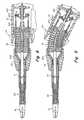
- FIG. 2is a cross-sectional plan view of the instrument of FIG. 1 as taken along line 2 - 2 of FIG. 1 ;
- FIG. 3is a cross-sectional end view showing the instrument of FIGS. 1 and 2 as taken along line 3 - 3 of FIG. 2 ;
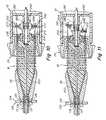
- FIG. 4is a fragmentary cross-sectional side views of the instrument illustrated in FIGS. 1-3 with the follower locked and the cable pinching member released;
- FIG. 5is a fragmentary cross-sectional side view of the instrument illustrated in FIGS. 1-3 with the instrument bent and with both the follower and cable pinching member locked;
- FIG. 6is a fragmentary cross-sectional side view of the instrument illustrated in FIGS. 1-3 with the follower released, the cable pinching member locked and the proximal end of the instrument re-positioned;
- FIG. 7is a fragmentary cross-sectional side view of the instrument illustrated in FIGS. 1-3 with the follower locked and the cable pinching member released to enable further positioning of the tool;
- FIG. 8is a fragmentary cross-sectional side view of an alternate embodiment of the instrument illustrated in FIGS. 1-3 using only a follower member;
- FIG. 9is a fragmentary cross-sectional side view of the instrument of FIG. 8 with the follower moved to its locked position;
- FIG. 10is a fragmentary cross-sectional side view of still another embodiment of the instrument illustrated in FIGS. 1-3 using a pinch member and wedge member;
- FIG. 11is a fragmentary cross-sectional side view of the instrument of FIG. 10 with the wedge member unlocked and the pinch member released;
- FIG. 12is a fragmentary cross-sectional side view of another embodiment of the instrument that also includes an angle locking mechanism
- FIG. 13is a cross-sectional view taken along line 13 - 13 of FIG. 12 ;
- FIG. 14is a fragmentary exploded view of the embodiment shown in FIGS. 12 and 13 ;
- FIG. 15is a fragmentary cross-sectional view of still another embodiment of the present invention.
- the instrument of the present inventionmay be used to perform minimally invasive procedures.
- “Minimally invasive procedure,”refers herein to a surgical procedure in which a surgeon operates through a small cut or incision, the small incision being used to access the operative site.
- the incision lengthranges from 1 mm to 20 mm in diameter, preferably from 5 mm to 10 mm in diameter. This procedure contrasts those procedures requiring a large cut to access the operative site.
- the flexible instrumentis preferably used for insertion through such small incisions and/or through a natural body lumen or cavity, so as to locate the instrument at an internal target site for a particular surgical or medical procedure.
- the introduction of the surgical instrument into the anatomymay also be by percutaneous or surgical access to a lumen, vessel or cavity, or by introduction through a natural orifice in the anatomy.
- the instrument of the present inventionmay be used in a variety of other medical or surgical procedures including, but not limited to, colonoscopic, upper GI, arthroscopic, sinus, thorasic, prostate, transvaginal, orthopedic and cardiac procedures.
- the instrument shaftmay be rigid, semi-rigid or flexible.
- surgical instrumentAlthough reference is made herein to a “surgical instrument,” it is contemplated that the principles of this invention also apply to other medical instruments, not necessarily for surgery, and including, but not limited to, such other implements as catheters, as well as diagnostic and therapeutic instruments and implements.
- One of the main features of the present inventionis the ability to re-position the control handle during a medical procedure.
- a clutch memberthat is actuable at the proximal end of the instrument to either couple the proximal and distal members to operate in unison, or to enable the handle to be moved freely for re-positioning without substantially effecting the distal member.
- Another embodiment of the present inventionuses the same clutch member, but further adds a means for pinching the cable actuation means so as to maintain a particular position at the distal end of the instrument while proximal re-positioning occurs.
- the aforementioned clutch memberis disclosed herein in a number of different embodiments and may be in the form of a follower that is used to terminate the proximal ends of the actuation cables, rather than having them terminate at the proximal bendable member.
- This followerwhen locked defines the terminations for the actuation cables and thus enables direct control between the proximal and distal bendable members.
- the followeris unlocked this enables the proximal control handle to be re-positioned without, in one embodiment, substantially effecting the position of the distal end of the instrument.
- Another feature that may be incorporated in the instrumentis a locking feature that maintains the proximal and distal bendable members in a particular bent condition.
- This lock controlallows the surgeon one less degree of freedom to concentrate on when performing certain tasks. By locking the bendable sections at a particular position, this enables the surgeon to be more hands-free for controlling other degrees of freedom of the instrument such as manipulation of the rotation knob to, in turn, control the orientation of the end effector.
- a locking mechanismthat is constructed using a ball and socket arrangement disposed about the proximal motion member that follows the bending action and in which an annular cinch ring is used to retain the ball and socket arrangement in a fixed particular position, and thus also maintain the proximal and distal bendable members in a particular bent condition, or in other words locked in that position.
- the cinch ringmay include a locking lever that is conveniently located adjacent to the instrument handle and that is easily manipulated to lock and unlock the cinch ring and, in turn, the position of the end effector.
- the cinch ringis also preferably rotatable so that the locking lever can be positioned conveniently or can be switched (rotated) between left and right handed users.
- This lock controlallows the surgeon one less degree of freedom to concentrate on when performing certain tasks. By locking the bendable sections at a particular position, this enables the surgeon to be more hands-free for controlling other degrees of freedom of the instrument such as manipulation of the rotation knob to, in turn, control the orientation of the end effector.
- the locking featuremay be implemented by means of a locking switch, in combination with, a handle socket and ball arrangement.
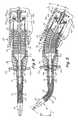
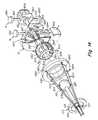
- FIG. 1is a perspective view of one embodiment of the surgical instrument 10 of the present invention.
- both the tool and handle motion members or bendable membersare capable of bending in any direction. They are interconnected via cables (preferably four cables) in such a way that a bending action at the proximal member provides a related bending at the distal member.
- the proximal bendingis controlled by a motion or deflection of the control handle by a user of the instrument.
- the surgeongrasps the handle and once the instrument is in position any motion (deflection) at the handle immediately controls the proximal bendable member which, in turn, via cabling 100 controls a corresponding bending or deflection at the distal bendable member. This action, in turn, controls the positioning of the distal tool.
- the proximal memberis preferably generally larger than the distal member so as to provide enhanced ergonomic control.
- the ratio of proximal to distal bendable member diametersmay be on the order of three to one.
- the bendable, turnable or flexible membersmay be arranged to bend in opposite directions by rotating the actuation cables through 180 degrees, or could be controlled to bend in virtually any other direction depending upon the relationship between the distal and proximal support points for the cables.
- amount of bending motion produced at the distal bending memberis determined by the dimension of the proximal bendable member in comparison to that of the distal bendable member.
- the proximal bendable memberis generally larger than the distal bendable member, and as a result, the magnitude of the motion produced at the distal bendable member is greater than the magnitude of the motion at the proximal bendable member.
- the proximal bendable membercan be bent in any direction (about 360 degrees) controlling the distal bendable member to bend in either the same or an opposite direction, but in the same plane at the same time. Also, as depicted in FIGS. 1 and 5 , the surgeon is able to bend and roll the instrument's tool about its longitudinal axis T to any orientation simply by rolling the axial rotation knob 24 about rotation direction R 1 .
- bendable membersThese members may also be referred to as turnable members, bendable sections or flexible members.
- terms such as “bendable section,” “bendable segment,” “bendable member,” or “turnable member”refer to an element of the instrument that is controllably bendable in comparison to an element that is pivoted at a joint.
- the term “movable member”is considered as generic to bendable sections and joints.
- the bendable elements of the present inventionenable the fabrication of an instrument that can bend in any direction without any singularity and that is further characterized by a ready capability to bend in any direction, all preferably with a single unitary or uni-body structure.
- a definition of a “unitary’ or “uni-body” structureis—a structure that is constructed only of a single integral member and not one that is formed of multiple assembled or mated components—.
- bendable membersmay be in the form of unitary structures, such as shown herein in FIGS. 2 and 4 , may be constructed of engageable discs, or the like, may include bellows arrangements or may comprise a movable ring assembly.
- bendable membersrefer to co-pending applications Ser. No. 11/505,003 filed on Aug. 16, 2006 and Ser. No. 11/523,103 filed on Sep. 19, 2006, both of which are hereby incorporated by reference herein in their entirety.
- FIG. 1shows one embodiment of the instrument of the present invention. Further details are illustrated in FIGS. 2 and 3 .
- FIGS. 4-7illustrate, in sequence, the manner in which the instrument can be re-positioned.
- FIG. 1depicts the surgical instrument 10 in one form in which the handle 12 is of in-line construction.
- the handlemay be of a pistol grip type.
- the instrument described hereinmay be used for laparoscopic surgery through the abdominal wall.
- an insertion siteat which there is disposed a cannula or trocar.
- the shaft 14 of the instrument 10is adapted to pass through the cannula or trocar so as to dispose the distal end of the instrument at the operative site.
- the end effector 16is depicted in FIG. 1 .
- the embodiment of the instrument shown in FIG. 1may be used with a sheath 98 to keep bodily fluids from entering the distal bending member 20 .
- a rolling motionis carried out with the instrument of the present invention. This occurs by virtue of the rotation of the rotation knob 24 relative to the handle 12 about axis P (refer to FIG. 2 ). This is represented in FIG. 1 by the rotation arrow R 1 . When the rotation knob 24 is rotated, in either direction, this causes a corresponding rotation of the instrument shaft 14 . This is depicted in FIG. 1 by the rotational arrow R 2 . This same motion also causes a rotation R 3 of the distal bendable member and end effector 16 about an axis that corresponds to the instrument tip, depicted in FIG. 5 as about the longitudinal tip or tool axis T.
- the handle 12via proximal bendable member 18 , may be tilted at an angle to the instrument shaft longitudinal center axis. This tilting, deflecting or bending may be considered as in the plane of the paper.
- this actioncauses a corresponding bend at the distal bendable member 20 to a position wherein the tip is directed along an axis and at a corresponding angle to the instrument shaft longitudinal center axis.
- FIG. 5shows this bending action.
- the bending at the proximal bendable member 18is controlled by the surgeon from the handle 12 by manipulating the handle in essentially any direction including in and out of the plane of the paper in FIG. 1 . This manipulation directly controls the bending at the proximal bendable member. Refer to FIG. 5 in which there is shown the axis U corresponding to the instrument shaft longitudinal axis. Refer also to the proximal bend angle B 1 between axes P and U, and the corresponding distal bend angle B 2 between axes U and T.
- the control at the handleis used to bend the instrument at the proximal motion member to, in turn, control the positioning of the distal motion member and tool.
- the “position” of the toolis determined primarily by this bending or motion action and may be considered as the coordinate location at the distal end of the distal motion member. Actually, one may consider a coordinate axis at both the proximal and distal motion members as well as at the instrument tip. This positioning is in three dimensions. Of course, the instrument positioning is also controlled to a certain degree by the ability of the surgeon to pivot the instrument at the incision point.
- the “orientation” of the toolrelates to the rotational positioning of the tool, from the proximal rotation control member, about the illustrated distal tip or tool axis T.
- the toolmay include a variety of articulated tools such as: jaws, scissors, graspers, needle holders, micro dissectors, staple appliers, tackers, suction irrigation tools and clip appliers.
- the toolmay include a non-articulated tool such as: a cutting blade, probe, irrigator, catheter or suction orifice.
- the surgical instrument of FIG. 1shows a preferred embodiment of a surgical instrument 10 according to the invention in use and may be inserted through a cannula at an insertion site through a patient's skin.
- Many of the components shown herein, such as the instrument shaft 14 , end effector 16 , distal bending member 20 , and proximal bending member 18may be similar to and interact in the same manner as the instrument components described in the co-pending U.S. application Ser. No. 11/185,911 filed on Jul. 20, 2005 and hereby incorporated by reference herein in its entirety.
- Many other components shown herein, particularly at the handle end of the instrument shown in FIG. 15 hereinmay be similar to components described in the co-pending U.S. application Ser. No.
- the control between the proximal bendable member 18 and distal bendable member 20is provided by means of the bend control cables 100 .
- the bend control cables 100extend through the instrument shaft 14 and through the proximal and distal bendable members such as shown in FIGS. 4 and 5 .
- the bend control cables 100are preferably constrained along substantially their entire length so as to prevent them from buckling as they are actuated.
- FIG. 1The instrument shown in FIG. 1 is of an in-line type. However, the principles of the present invention may also apply to other forms of handles such as a pistol grip handle, such as depicted in FIG. 15 herein.
- FIG. 1there is also shown a jaw clamping or actuation means that is comprised mainly of the lever 22 .
- the lever 22controls the main tool actuation cable 38 .
- various tool actuation mechanismsrefer to any of the aforementioned co-pending applications.
- the instrument shaft 14includes an outer shaft tube 32 that may be constructed of a light weight metal material or may be a plastic material. See the cross-sectional view of FIG. 3 taken through the instrument shaft at the very proximal end thereof and along line 3 - 3 of FIG. 2 .
- the proximal end of the tube 32is received by the adaptor 26 , as depicted in FIG. 2 .
- the distal end of the tube 32is secured to the distal bendable member 20 .
- a support tube 34that is preferably constructed of a plastic material. Tube 34 extends between the distal bendable or flexible member 20 and the proximal bendable or flexible member 18 .
- the jaw actuator cable 38extends within this support tube 34 .
- the handle end of the instrumentmay be tipped in any direction as the proximal bendable member is constructed and arranged to enable full 360 degree bending.
- This movement of the handle relative to the instrument shaftbends the instrument at the proximal bendable member 18 .
- This actionin turn, via the bend control cables 100 , bends the distal bendable member in the same direction.
- opposite direction bendingcan be used by rotating or twisting the control cables through 180 degrees from one end to the other end thereof.
- the handle 12has an in-line form with an associated actuation lever 22 supported therefrom.
- the tool actuation lever 22is shown in FIG. 1 and is pivotally attached at the base of the handle.
- the lever 22actuates a slider (not shown) that controls the tool actuation cable 38 that extends from the slider to the distal end of the instrument.
- the cable 38controls the opening and closing of the jaws, and different positions of the lever control the force applied at the jaws.
- FIGS. 2-4In this instrument the distal bendable member 20 is shown without any protective sheath so as to show some of the details of the distal bendable member 20 .
- the distal bendable memberis comprised of spaced discs 110 that define therebetween spaced slots 112 . Ribs 111 may connect between adjacent discs in a manner similar to that described in the afore-mentioned U.S. application Ser. No. 11/185,911. For further details of the tool end of the instrument reference may be made to the aforementioned Ser. No. 11/528,134 filed on Sep. 27, 2006.
- the proximal bendable member 18may also be constructed as a unitary or uni-body slotted structure including a series of flexible discs 130 that define therebetween slots 132 .
- a “unitary” or “uni-body” structuremay be defined as one that is constructed for use in a single piece and does not require assembly of parts. Connecting ribs (not shown) may extend between adjacent discs 130 .
- Both of the bendable memberspreferably have a rib pattern in which the ribs are disposed at a preferred 60 degree variance from one rib to an adjacent rib. This has been found to provide an improved bending action. It was found that by having the ribs disposed at intervals of less than 90 degrees therebetween improved bending was possible.
- the ribsmay be disposed at intervals of from about 35 degrees to about 75 degrees from one rib to an adjacent one. By using an interval of less than 90 degrees the ribs are more evenly distributed. As a result the bending motion is more uniform at any orientation.
- both of the bendable membersmay be made of a highly elastic polymer such as PEBAX (Polyether Block Amide), but could also be made from other elastic and resilient materials.
- the rotation knob 24is provided with a proximal hub 25 which supports the proximal end of the proximal bending member 18 .
- FIG. 2shows the cabling 100 extending through the proximal bendable member 18 and the hub 25 . Rather than having the bend control cables terminating at the proximal bendable member or hub, these cables terminate at the clutch member which is also referred to herein as the follower mechanism 140 .
- the cable schemeuse bend control cables that are relatively stiff and yet are bendable.
- the stiffer cablesallow for, not only “pulling”, but also “pushing” action thereof. This enables enhanced control via the cabling as control is provided, not only when a cable is “pulled”, but also when a cable is “pushed”. This makes for a more uniform control via the cables.
- the cables 100are supported in relatively narrow lumens or passageways to prevent buckling when being pushed. This may be facilitated by, inter alia, the provision of a shaft filler as described in co-pending Ser. No. 11/649,352 filed on Jan. 2, 2007.
- the cablesare confined so that they do not distort within the instrument itself.
- one of the main features of the present inventionis the ability to re-position the control handle during a medical procedure.
- a clutch or follower memberthat is actuable at the proximal end of the instrument to either couple the proximal and distal members to operate in unison, or to enable the handle to be moved freely for re-positioning without substantially effecting the distal member.
- FIGS. 1-7Another embodiment of the present invention, as illustrated in FIGS. 1-7 , uses the same clutch or follower member, but further adds a pinching member for the cable actuation means so as to maintain a particular position at the distal end of the instrument while proximal re-positioning occurs.
- the follower 140is shown in FIGS. 2-7 .
- the follower or clutch mechanism 140includes, inter alia, an anchor ring 142 that provides the primary support for the bend control cables 100 , as well as a split ball 125 that supports the rider 148 .
- a wedge member 180is actuated to lock or unlock the split ball 125 .
- the anchor ring 142includes diametrically disposed pins 172 that are accommodated in elongated slots of the opposed rearwardly extending fingers 176 .
- the fingers 176extend from the rotation knob hub 25 .
- the individual cables 100are attached to the anchor ring by means of the end lugs 102 .
- a spring or resilient pad 104is preferably disposed between the lug 102 and anchor ring 142 .
- Each of the cables 100also preferably is supported in a stiffener tube 105 so that the cables are properly confined as they are actuated and do not buckle.
- the clutch mechanism 140is adapted to be in either a locked position in which the bend control cables 100 are fixedly terminated at the anchor ring 142 , or what may be termed an unlocked position in which the rider is free to pivot or rotate on the split ball in order to enable a re-positioning of the handle to a new position. From that new position the clutch mechanism may then be re-engaged to enable control of the distal end of the instrument from the proximal handle. In other words, when re-engaged, the rider 148 is then locked to the split ball member 125 .
- the clutch mechanism 140When the instrument illustrated in this embodiment is in a straight in-line position, as shown in FIG. 4 , then the clutch mechanism 140 , and particularly the anchor ring 142 extends substantially transverse to the center axis P.
- the handle 12When the handle 12 is bent, such as in the position shown in FIG. 5 then it is noted that the follower or clutch mechanism 140 maintains its transverse position relative to the longitudinal axis P.
- the clutch mechanism 140is to be locked then the wedge member 180 engages the split ball 125 , urging the ball against the rider and this locks the position of the anchor ring 142 and thus also locks the position of the bend control cables 100 .
- the wedge member 180disengages from the split ball 125 and this enables re-positioning of the control cables 100 as the ball member is no longer engaging the rider.
- the anchor ring 142is allowed to rotate relative to the rider in response to the rotation of the knob 24 .
- the clutch or locking mechanism 140includes, in addition to the anchor ring 142 and the rider 148 , the retaining ring 149 . Fastening screws or the like may be used for securing together the rider 148 and the retaining ring 149 about the spherical ball 125 as illustrated in FIG. 2 .
- the ball 125is also supported at its center by means of the sleeve 152 that may have a flange on one end adjacent to the wall 151 and a securing nut or flange at the opposite end.
- the wedge member 180is adapted to slide on the sleeve 152 into the slit 147 in the spherical split ball 125 .
- the cross-sectional view of FIG. 2illustrates the ball 125 with its slit 147 .
- FIG. 2also illustrates the wedge member 180 .
- the conical wedge 180may be moved by means of a button arrangement that includes the lock button 155 .
- This buttonmay be considered as having opposite ends 155 A and 155 B.
- the button end 155 Bis moved in the direction of arrow 155 C (see FIG. 7 ) then this locks the clutch mechanism of the instrument.
- the button end 155 Ais depressed toward the handle housing in the direction of the arrow 155 D (see FIG. 6 ) then this releases the clutch mechanism.
- the conical wedge member 180is moved by means of the wedge 154 that is supported by the button 155 .
- the first embodiment shown in FIGS. 1-7also includes a means for pinching the bend control cables so that the distal instrument position can be maintained while the proximal instrument position is re-positioned.
- the second embodiment illustrated herein in FIGS. 8 and 9does not use the pinching means, but uses only the proximal re-positioning mechanism.
- the pinching means 133is illustrated as including pinch ring 134 , connecting links 135 , ring-shaped wedge 136 and resilient conical ring 137 .
- FIG. 2shows the pinch member in its non-pinched state.
- FIG. 3is a cross-sectional view through the pinch means 133 illustrating further details of the pinch member.
- the pinch memberis disposed, in this embodiment, at the distal end of the adaptor 26 or at the proximal end of the instrument shaft. This is a convenient location for actuation by the instrument user but could also be located at other positions relative to the instrument handle.
- FIG. 2In the position of FIG. 2 the pinch member is released with the pinch ring 134 disposed at the left side of the slot 138 . In that position the wedge 136 is dis-engaged from the cables 100 and thus the cables are free to be moved to control instrument bending.
- FIG. 5illustrates the pinch ring 134 having been moved to the locked position, to the right in the slot 138 . This action pinches the cables 100 between the wedge 136 and the resilient cone 137 . This pinching action holds the position at the distal end of the instrument (end effector) at the position at which it is at the time that the pinch member is locked. Once this pinching is initiated then the handle can be freed for re-positioning (clutch mechanism released and subsequently engaged at a new position).
- FIG. 2shows the clutch mechanism unlocked with the wedge member 180 out of engagement with the split ball 125 .
- FIG. 2also shows the pinch member in its un-pinched position.
- FIG. 4shows the instrument in an in-line position with the clutch mechanism 140 locked and the pinch member in its non-pinched position. In the position of FIG. 4 the instrument is arranged so that it can be readily bent in any direction. With the clutch mechanism locked the bend control cables are essentially in an operable state.
- FIG. 5shows the cable and clutch arrangement when the instrument handle is moved to bend the proximal bendable member which, in turn, bends the distal bendable member and tool.
- the handleis bent at an angle B 1 and the tool is correspondingly bent at the illustrated angle B 2 .
- FIG. 5shows the proximal bendable member 18 bent causing a corresponding bending at the distal bendable member 20 .
- the pinch member 133is then locked impeding the bend control cables. This action holds the distal end of the instrument at the position shown in FIG. 5 regardless of what happens at the proximal end of the instrument.
- FIG. 5shows the clutch mechanism still locked.
- FIG. 6now illustrates the next possible step in the instrument operation where the pinch member 133 is maintained locked holding the distal position while the proximal clutch mechanism has been unlocked or released allowing the instrument handle to be re-positioned to the straight position shown in FIG. 6 .
- the distal bend(angle B 2 ) is maintained even though the proximal handle position has been re-positioned to a straight position.
- the re-positioningcauses the clutch mechanism to tilt relative to the handle longitudinal axis in order to compensate for the change in position to the straight position.
- a straight positionhas been shown here it is understood that the handle and proximal bendable member can be re-positioned to virtually any desired position before the clutch mechanism is again engaged.
- FIG. 7shows the handle 12 and proximal bendable member 18 moved downwardly so as to further position the distal bendable member 20 and end effector 16 .
- This actionas noted in FIG. 7 , further deflects the end effector 16 at a greater angle B 3 .
- FIG. 7it is noted that before the control occurs the pinch member is released, shown in FIG. 7 , by the pinch ring 134 having been moved distally.
- FIGS. 8 and 9for another embodiment of the present invention that is substantially the same as shown in the first embodiment that has been described herein, except that only the clutch mechanism 140 is used without the pinch member.
- FIGS. 8 and 9the same reference characters are used, where appropriate, as used in the first embodiment.
- FIG. 8shows the instrument in an in-line position with the clutch mechanism 140 disengaged. From that position, by way of example, the handle 12 can be moved downwardly to the position of FIG. 9 .
- FIG. 9shows the handle bent downwardly but with the distal end unbent.
- FIG. 9also shows the clutch mechanism 140 then engaged or locked so that bend control can commence. From the position of FIG. 9 the surgeon can then move the handle in any direction including a full 360 degree movement.
- FIGS. 10 and 11depict still another embodiment of the present invention that incorporates both a clutch mechanism as well as a pinch member for restraining the cables.
- FIGS. 10 and 11depict a fragmentary portion of the handle 12 , a portion of the instrument shaft 14 , the proximal bendable member 18 , the rotation knob 24 and the adaptor 26 .
- the pinching member 133 as described in FIGS. 10 and 11is substantially identical to that described in FIGS. 1-3 .
- the pinching memberincludes pinch ring 134 , connecting links 135 , the ring-shaped wedge 136 and resilient chronicle ring 137 .
- the components of the pinch memberare disposed at approximately the same position as illustrated in the first embodiment shown in the cross-sectional view of FIG. 2 .
- the clutch mechanismis different than that described in the earlier embodiments and is actuated in a somewhat different manner.
- This actuationis formed by means of moving the rotation knob 24 axially relative to the handle, such as between the two positions illustrated in respective FIGS. 10 and 11 .
- the follower or clutch mechanism 240includes, inter alia, an anchor ring 242 that provides the primary support for the bend control cables 200 , as well as a split ball 225 that supports the rider 248 .
- the split ball 225is fixedly secured to the rotation knob 24 and moves with the longitudinal displacement thereof.
- a wedge member 280is supported from the handle wall 281 and is engageable and disengageable with the split ball 225 .
- the wedge member 280is fixed in position while the split ball 225 transitions toward and away from the wedge member 280 to provide respective locking and unlocking of the clutch mechanism 240 .
- the anchor ring 242includes diametrically disposed pins 272 that are accommodated in elongated slots of the opposed rearwardly extending fingers 276 .
- the fingers 276extend from the rotation knob hub.
- the individual cables 200are attached to the anchor ring 242 by means of the end lugs 202 .
- a spring or resilient pad 204is preferably disposed between the lug 202 and the anchor ring 242 .
- Each of the cables 200also preferably is supported in a stiffener tube (not shown in FIGS. 10 and 11 ) so that the cables are properly confined as they are actuated and do not buckle.
- Four control cablesmay be used or fewer or greater numbers of control cables may be used.
- the clutch mechanism 240is adapted to be in either a locked position in which the bend control cables 200 are fixedly terminated at the anchor ring 242 , or what may be termed an unlocked or released position in which the rider is free to pivot or rotate on the split ball in order to enable a repositioning of the handle to a new position. From that new position the clutch mechanism may then be re-engaged to enable control of the distal end of the instrument form the proximal handle.
- FIG. 10this cross-sectional view depicts the clutch mechanism in its clutched or locked position.
- the rotation knob 24has been moved to the right so that there is an engagement between the split ball 225 and the wedge member 280 . This causes the split ball to expand and contact the rider 248 to thus maintain a fixed position between the rider and the split ball.
- FIG. 11depicts the rotation knob at a more distal position thus releasing the engagement between the wedge member 280 and split ball 225 , wherein the rider is free to pivot or rotate on the split ball in order to enable a repositioning of the handle.
- the same sequence previously described in connection with FIGS. 1-7may also apply to the embodiment in FIGS. 10 and 11 whereby the pinch member is engageable to maintain a pre-selected position at the distal end of the instrument while the clutch mechanism is either locked or unlocked to enable either further control of the distal end of the instrument or a repositioning of the handle.
- the anchor ring 242is able to rotate relative to the rider 248 such as upon rotation of the rotation knob 24 .
- the wedge member 280forces the split ball apart thus essentially holding the rider at a fixed position on the split ball 225 .
- the rotation knob 24is moved to the position shown in FIG. 11 , then the split ball is no longer expanded and the rider is thus free to move on the split ball 225 .
- FIG. 12is a fragmentary cross-sectional view illustrating the instrument.
- FIG. 14is an exploded perspective view of components of the instrument.
- the instrument that is depicted in FIGS. 12-14also includes both a clutch mechanism and a pinch means, as well as a means for locking a particular position between the handle and tool.
- the instrument shown in the cross-sectional view of FIG. 12incorporates a separate locking member for locking a particular position of the instrument.
- co-pending application Ser. No. 11/605,694 filed on Nov. 28, 2006which is hereby incorporated by reference herein.
- FIG. 12is a fragmentary cross-sectional view of the instrument of this embodiment showing only portions of the handle 12 and instrument shaft 14 .
- FIG. 12also depicts the distal bendable member 20 which may be of unitary construction and the end effector 16 .
- the cables 800are shown extending through the instrument shaft and coupled to the end effector 16 .
- the construction of the handleis only shown in a fragmentary view at the interface with the proximal bendable member 818 .
- the handleincludes a lever (not shown) for actuating the tool actuating cable that extends through to the end effector.
- FIG. 12it is the tilting of the handle relative to the adaptor 826 that controls the distal bending at the distal bendable member 20 .
- the rotation knob 824is integral with the adaptor 826 and provides for rotation of the instrument shaft, particularly rotation of the outer tube 832 of the instrument shaft relative to an inner tube of the instrument shaft.
- the rotation of the outer tube 832 of the instrument shaftrotates the distal bendable member and the end effector that is supported at the distal end thereof. This provides for rotation at the tip of the instrument about a distal tip axis such as the axis P in FIG. 12 .
- the outer shaft tube 832is secured within the adaptor 826 .
- the inner tube 834is supported relative to the outer tube 832 .
- the cross-sectional views of FIGS. 12 and 13illustrate four bend control cables 800 .
- Within the instrument shaftthere may also be provided spacers (not shown) with guide slots for accommodating the cables 800 .
- four control cables 800are provided as illustrated in the cross-sectional view of FIG. 13 , in other embodiments fewer or greater numbers of cables may be provided.
- the very proximal end 836 of the inner tube 834supports the ball 815 .
- the ball 815is fixedly mounted on the end of the inner member which does not rotate.
- the tool actuation cablepasses through the ball 815 .
- the ball 815is provided with a somewhat conical cavity 817 .
- the tilting of the end effector in three dimensionsis performed by the handle having the capability of likewise being bent or tilted in three dimensions relative to the adaptor 826 .
- the handlemay be provided in two halves that define therebetween the ball socket 825 .
- the exploded perspective view of FIG. 14illustrates the spherical ball 815 and the accommodating ball socket 825 as part of the handle 12 .
- the ball 815is provided with diametrically disposed pins 827 that are accommodated in diametrically disposed slots 828 in the handle of the ball socket 825 . This pin and slot arrangement enables the handle to move in three dimensions relative to the ball 815 .
- the pin 827may transition in the slot 828 when the handle is moved in the plane of the paper in FIG. 12 . Also, the handle can pivot relative to the pin 827 as the handle is moved in and out of the plane of the paper in FIG. 12 . This provides three dimensional positioning.
- FIG. 12also illustrates the rotating anchor ring 840 that is supported relative to the handle and that carries the very proximal end of each of the cables 800 .
- the anchor ring 840includes four holes disposed at 90 degrees to each other and that receive the proximal ends (lugs 841 ) of each of the cables 800 .
- a spring or resilient member identified at 842may be provided between each of the cable terminations and the rotating anchor ring 840 .
- the handleis tipped downwardly. As long as the cables 800 are not twisted within the instrument shaft, then this tilting of the handle causes a corresponding upward movement of the end effector by way of the distal bendable member 20 .
- the anchor ring 840is free to rotate relative to the rider 880 for rotating the distal tip of the instrument.
- the anchor ring 840represents the means for holding the very proximal ends of the cables 800 .
- the rotating anchor ring 840is the interface between the rotation knob 824 and the handle.
- diametrically disposed pins 849 on the ring 840that are accommodated in arcuate slots 850 in the rotation knob 824 .
- This pin and slot arrangementenables the rotation knob to be rotated to, in turn, rotate the outer tube of the instrument shaft and the end effector.
- the pins 849move in slots 850 to enable this rotational movement.
- the pin 849 and slot 850enable rotational movement of the rotation knob 824 regardless of the position of the handle relative to the instrument shaft.
- the cross-sectional view of FIG. 12also depicts at the handle two separate button controls. One of these controls is for controlling the locking of the instrument at a particular bent condition. This is controlled by the button arrangement indicated at A.
- the other button arrangement indicated at B in the cross-sectional view of FIG. 12controls the clutching in accordance with this embodiment that enables a repositioning of the handle.
- the locking mechanism associated with the button arrangement Aincludes the sleeve 852 that supports a flange 853 at one end and the cup 854 at the other end.
- the cup 854is supported so as to slide toward and away from the ball 815 .
- the sleeve 852is adapted to transition linearly toward and away from the ball 815 . In one position the sleeve is disposed away from the ball and in the opposite position the cup 854 is moved into contact with the ball for locking the position of the handle relative to the ball 815 . Once in this locked position then through the proximal and distal bendable members the entire instrument is locked in position with the exception that the tip can be rotated via the rotation knob 824 .
- the translation of the sleeve 852is controlled from the wedge 856 .
- the wedge 856has a flat surface that bears against the flange 853 and has a tapered surface that engages a tapered wall of the handle.
- the wedge 856also includes an elongated slot that provides sufficient clearance so that, as the wedge member 856 is moved between its locked and unlocked positions, there is no contact with the tool actuation cable and its associated sheath.
- the wedge member 856is controlled by means of a pair of buttons. This includes a lock button 860 supported at the end of shaft 861 . Shaft 861 is fixed to the wedge member 856 . On the opposite side of the wedge member 856 , there is a release button 862 that is supported from the wedge member by means of the shaft 863 .
- the lock button 860When the lock button 860 is pushed inward toward the handle, this causes the wedge member 856 to move against the tapered surface thus moving the sleeve 852 longitudinally so that the cup 854 applies a clamping pressure or force on the ball 815 . When this occurs the handle is held in a fixed position relative to the ball 815 .
- the instrumentis maintained in that position with the end effector at the particular corresponding position.
- the locking membermay be released by pushing on the release button 862 so as to move the wedge member 856 longitudinally in the opposite direction. This releases the tension on the sleeve 852 so that the cup 854 is no longer in intimate contact with the ball 815 . This enables the handle to be moved in any three dimensional position relative to the adaptor 826 . Biasing means or detent means may be associated with this locking mechanism.
- the other button arrangement B depicted in FIG. 12is for controlling the repositioning of the handle. This action controls the interface between the rider 880 that supports the anchor ring 840 and the outer surface 881 of the handle end that forms the socket for the ball 815 .
- This outer surface 881supports four arcuate plates 882 in accommodating recesses in the surface 881 .
- the plates 882are adapted to be moved outwardly in the direction of the arrows 883 so as to bear against the rider 880 . These plates bear against the rider 880 in the locked position of the clutch mechanism. In the released position of the clutch mechanism the plates 882 are released and do not provide any bearing force against the rider 880 .
- the plates 882are actuated by means of four tapered wires 885 that, at one end, extend under respective plates 882 and at the opposite end are held at the button arrangement B, more particularly, at the base 887 .
- the base 887is supported by means of end pins 888 that extend through diagonal slots 889 of the frame 890 .
- a button 894that is connected to the frame 890 .
- an locking mechanism or angle locking means 440is used that includes a ball and socket arrangement that is basically disposed over the proximal bendable member 418 and that follows the bending at the proximal bendable member.
- the locking mechanismhas locked and unlocked positions, is disposed about the proximal movable or bendable member and is manually controlled so as to fix the position of the proximal movable member relative to the handle in the locked position thereof.
- the locking mechanismcomprises a ball member and a compressible hub that defines a socket member.
- the hubmay be a split hub and the locking mechanism is illustrated as including a cinch ring 420 disposed about the split hub and a locking lever 421 mounted on the cinch ring for closing the cinch ring about the hub to lock the hub against the spherical ball member 422 .
- the cinch ring 420interlocks with the hub but is able to rotate relative thereto when in the unlocked position.
- the “ball” partis basically formed by the ball member 422
- the “socket” partis basically formed by an extension of the handle.
- the locking mechanismlocks the proximal bendable member in a desired position and by doing that also locks the position of the distal bendable member and tool.
- the proximal bending member 418although it is enclosed by the ball and socket arrangement, still allows the instrument shaft 414 and the proximal bending member 418 , along with the cabling 400 , to rotate freely (rotation knob 424 ) while also allowing the axis of the instrument shaft to be angled relative to the axis of the handle in a free, or alternately, locked mode.
- the ball member 422which is shown in FIG. 12 .
- the ball member 422includes a distal neck 406 that is contiguous with a partially spherical ball end having a spherical outer surface 404 .
- the neck 406is basically disposed over the adaptor 426 and conical portion 419 of the proximal bendable member 418 , while the ball portion is mainly disposed over the primary part of the proximal bendable member 418 .
- the ball member 422is adapted to sit within a socket that is formed in the handle in the form of a hub 402 that can be collapsed about the ball member 422 by radially compressing the cinch ring 420 .
- this locking constructionrefer to additional details found in co-pending Ser. No. 11/649,352 which are hereby incorporated by reference herein.
- the rotation knob 424is provided with a proximal hub 425 which supports the proximal end of the proximal bending member 418 .
- FIG. 15shows the cabling 400 extending through the proximal bendable member 418 and the hub 425 . Rather than having the bend control cables terminating at the proximal bendable member or hub, these cables terminate at the clutch member which is also referred to herein as the follower mechanism 540 .
- the follower or clutch mechanism 540includes, inter alia, an anchor ring 542 that provides the primary support for the bend control cables 400 , as well as a split ball 525 that supports the rider 548 .
- a wedge member 580is actuated to lock or unlock the split ball 525 .
- the individual cables 400are attached to the anchor ring by means of the end lugs 502 .
- a spring or resilient pad 504is preferably disposed between the lug 502 and anchor ring 542 .
- Each of the cables 400also preferably is supported in a stiffener tube 505 so that the cables are properly confined as they are actuated and do not buckle.
- the stiffener tube 505is shown in FIG. 15 disposed between the hub 425 and the anchor ring 542 .
- the clutch mechanism 540is adapted to be in either a locked position in which the bend control cables 400 are fixedly terminated at the anchor ring 542 , or what may be termed an unlocked position in which the rider is free to pivot or rotate on the split ball in order to enable a re-positioning of the handle to a new position. From that new position the clutch mechanism may then be re-engaged to enable control of the distal end of the instrument from the proximal handle. In other words, when re-engaged, the rider 548 is then locked to the split ball member 525 . In both locked and unlocked positions of the mechanism 540 the anchor ring 542 is allowed to rotate relative to the rider in response to the rotation of the knob 424 .
- the wedge member 580engages the split ball 525 , urging the ball against the rider and this locks the position of the anchor ring 542 and thus also locks the position of the bend control cables 400 .
- the wedge member 580disengages from the split ball 525 and this enables a re-positioning of the handle 412 and the control cables 400 as the ball member is no longer engaging the rider.
- the mechanism 540 shown in FIG. 15may be substantially the same as that shown in FIG. 2 herein.
- the conical wedge 580may be moved by means of a button arrangement (not shown in FIG. 15 ) such as that described in FIG. 2 herein. This button may be considered as having opposite ends and is moveable in opposite directions to lock or unlock the clutch mechanism.
- the conical wedge member 580is moved by means of the wedge 554 that is supported by the button arrangement.
- the embodiment shown in FIG. 15also includes a means for pinching the bend control cables so that the distal instrument position can be maintained while the proximal instrument position is re-positioned.
- the pinching means 133is illustrated as including pinch ring 134 , connecting links 135 , ring-shaped wedge 136 and resilient conical ring 137 , essentially the same as shown and discussed before in FIG. 2 .
- FIG. 15shows the pinch member in its non-pinched state.
- the pinch memberis disposed, in this embodiment, at the distal end of the adaptor 426 or at the proximal end of the instrument shaft. This is a convenient location for actuation by the instrument user but could also be located at other positions relative to the instrument handle.
- the movable membersmay alternatively be of other constructions including, but not limited to, engageable discs, bellows arrangements, a movable ring assembly or ball and socket members.
- bendable membersrefer to co-pending applications Ser. No. 11/505,003 filed on Aug. 16, 2006 and Ser. No. 11/523,103 filed on Sep. 19, 2006, both of which are hereby incorporated by reference herein in their entirety.
Landscapes
- Health & Medical Sciences (AREA)
- Life Sciences & Earth Sciences (AREA)
- Surgery (AREA)
- Molecular Biology (AREA)
- Engineering & Computer Science (AREA)
- Biomedical Technology (AREA)
- Heart & Thoracic Surgery (AREA)
- Medical Informatics (AREA)
- Nuclear Medicine, Radiotherapy & Molecular Imaging (AREA)
- Animal Behavior & Ethology (AREA)
- General Health & Medical Sciences (AREA)
- Public Health (AREA)
- Veterinary Medicine (AREA)
- Ophthalmology & Optometry (AREA)
- Surgical Instruments (AREA)
- Endoscopes (AREA)
Abstract
Description
Claims (33)
Priority Applications (5)
| Application Number | Priority Date | Filing Date | Title |
|---|---|---|---|
| US11/805,420US8409245B2 (en) | 2007-05-22 | 2007-05-22 | Surgical instrument |
| JP2010509338AJP2010527690A (en) | 2007-05-22 | 2008-05-12 | Surgical equipment |
| PCT/US2008/006022WO2008153654A1 (en) | 2007-05-22 | 2008-05-12 | Surgical instrument |
| EP08754349AEP2152170A1 (en) | 2007-05-22 | 2008-05-12 | Surgical instrument |
| CN2008800187167ACN101677814B (en) | 2007-05-22 | 2008-05-12 | Surgical instrument |
Applications Claiming Priority (1)
| Application Number | Priority Date | Filing Date | Title |
|---|---|---|---|
| US11/805,420US8409245B2 (en) | 2007-05-22 | 2007-05-22 | Surgical instrument |
Publications (2)
| Publication Number | Publication Date |
|---|---|
| US20080294191A1 US20080294191A1 (en) | 2008-11-27 |
| US8409245B2true US8409245B2 (en) | 2013-04-02 |
Family
ID=40073123
Family Applications (1)
| Application Number | Title | Priority Date | Filing Date |
|---|---|---|---|
| US11/805,420Active2029-11-30US8409245B2 (en) | 2007-05-22 | 2007-05-22 | Surgical instrument |
Country Status (5)
| Country | Link |
|---|---|
| US (1) | US8409245B2 (en) |
| EP (1) | EP2152170A1 (en) |
| JP (1) | JP2010527690A (en) |
| CN (1) | CN101677814B (en) |
| WO (1) | WO2008153654A1 (en) |
Cited By (21)
| Publication number | Priority date | Publication date | Assignee | Title |
|---|---|---|---|---|
| US20110213347A1 (en)* | 2006-07-11 | 2011-09-01 | Cambridge Endoscopic Devices, Inc. | Surgical instrument |
| DE102013222041A1 (en)* | 2013-10-30 | 2015-04-30 | Digital Endoscopy Gmbh | Deflection movement transmission device, endoscope deflecting control and endoscope |
| WO2017132386A1 (en)* | 2016-01-27 | 2017-08-03 | Boston Scientific Scimed, Inc. | Endoscope device and method |
| US9962179B2 (en) | 2011-04-06 | 2018-05-08 | Medrobotics Corporation | Articulating surgical tools and tool sheaths, and methods of deploying the same |
| US9993300B2 (en) | 2013-02-08 | 2018-06-12 | Olympus Corporation | Manipulator |
| US10016187B2 (en) | 2013-05-20 | 2018-07-10 | Medrobotics Corporation | Articulating surgical instruments and method of deploying the same |
| US20190125469A1 (en)* | 2017-11-02 | 2019-05-02 | National Chiao Tung University | Minimally invasive surgical instruments with terminal steerable mechanism |
| USD874655S1 (en) | 2018-01-05 | 2020-02-04 | Medrobotics Corporation | Positioning arm for articulating robotic surgical system |
| US10617438B2 (en) | 2015-10-20 | 2020-04-14 | Lumendi Ltd. | Medical instruments for performing minimally-invasive procedures |
| US10842473B2 (en) | 2017-10-30 | 2020-11-24 | Ethicon Llc | Surgical instrument having dual rotatable members to effect different types of end effector movement |
| US10932804B2 (en) | 2017-10-30 | 2021-03-02 | Ethicon Llc | Surgical instrument with sensor and/or control systems |
| US11129634B2 (en) | 2017-10-30 | 2021-09-28 | Cilag Gmbh International | Surgical instrument with rotary drive selectively actuating multiple end effector functions |
| US11147635B1 (en) | 2020-06-19 | 2021-10-19 | Remedy Robotics, Inc. | Systems and methods for guidance of intraluminal devices within the vasculature |
| US11446081B2 (en) | 2015-10-20 | 2022-09-20 | Lumedi Ltd. | Medical instruments for performing minimally-invasive procedures |
| US11504104B2 (en) | 2015-10-20 | 2022-11-22 | Lumendi Ltd. | Medical instruments for performing minimally-invasive procedures |
| US20230100909A1 (en)* | 2021-08-27 | 2023-03-30 | Michael Peck | Sequential stylet |
| US11690683B2 (en) | 2021-07-01 | 2023-07-04 | Remedy Robotics, Inc | Vision-based position and orientation determination for endovascular tools |
| US11707332B2 (en) | 2021-07-01 | 2023-07-25 | Remedy Robotics, Inc. | Image space control for endovascular tools |
| US11723636B2 (en)* | 2013-03-08 | 2023-08-15 | Auris Health, Inc. | Method, apparatus, and system for facilitating bending of an instrument in a surgical or medical robotic environment |
| US12121307B2 (en) | 2021-07-01 | 2024-10-22 | Remedy Robotics, Inc. | Vision-based position and orientation determination for endovascular tools |
| US12419658B2 (en) | 2015-10-20 | 2025-09-23 | Lumendi AG | Medical instruments for performing minimally-invasive procedures |
Families Citing this family (52)
| Publication number | Priority date | Publication date | Assignee | Title |
|---|---|---|---|---|
| US8409175B2 (en)* | 2005-07-20 | 2013-04-02 | Woojin Lee | Surgical instrument guide device |
| US8105350B2 (en) | 2006-05-23 | 2012-01-31 | Cambridge Endoscopic Devices, Inc. | Surgical instrument |
| WO2008076330A1 (en) | 2006-12-15 | 2008-06-26 | Soteira, Inc. | Drills and methods for vertebrostenting |
| US9005238B2 (en)* | 2007-08-23 | 2015-04-14 | Covidien Lp | Endoscopic surgical devices |
| US9023014B2 (en)* | 2007-09-21 | 2015-05-05 | Covidien Lp | Quick connect assembly for use between surgical handle assembly and surgical accessories |
| US8870867B2 (en)* | 2008-02-06 | 2014-10-28 | Aesculap Ag | Articulable electrosurgical instrument with a stabilizable articulation actuator |
| US8439898B2 (en)* | 2008-06-17 | 2013-05-14 | Usgi Medical, Inc. | Endoscopic tissue anchor deployment |
| WO2009155319A1 (en) | 2008-06-17 | 2009-12-23 | Soteira, Inc. | Devices and methods for fracture reduction |
| USD614299S1 (en)* | 2008-06-23 | 2010-04-20 | Karl Storz Gmbh & Co. Kg | Handle for medical instrument |
| US9737334B2 (en) | 2009-03-06 | 2017-08-22 | Ethicon Llc | Methods and devices for accessing a body cavity |
| WO2010111246A1 (en) | 2009-03-23 | 2010-09-30 | Soteira, Inc. | Devices and methods for vertebrostenting |
| USD625814S1 (en)* | 2009-04-03 | 2010-10-19 | Karl Storz Gmbh & Co. Kg | Surgical instrument for use in single-access surgery |
| USD626227S1 (en)* | 2009-04-03 | 2010-10-26 | Karl Storz Gmbh & Co. Kg | Surgical instrument for use in single-access surgery |
| USD625812S1 (en)* | 2009-04-03 | 2010-10-19 | Karl Storz Gmbh & Co. Kg | Surgical instrument for use in single-access surgery |
| USD625810S1 (en)* | 2009-04-03 | 2010-10-19 | Karl Storz Gmbh & Co. Kg | Surgical instrument for use in single-access surgery |
| FR2943906B1 (en) | 2009-04-03 | 2013-03-22 | Univ Pierre Et Marie Curie Paris 6 | SURGICAL INSTRUMENT. |
| USD624651S1 (en)* | 2009-04-03 | 2010-09-28 | Karl Storz Gmbh & Co. Kg | Surgical instrument for use in single-access surgery |
| USD624652S1 (en)* | 2009-04-03 | 2010-09-28 | Karl Storz Gmbh & Co. Kg | Surgical instrument for use in single-access surgery |
| USD625806S1 (en)* | 2009-04-03 | 2010-10-19 | Karl Storz Gmbh & Co. Kg | Surgical instrument for use in single-access surgery |
| FR2943907B1 (en) | 2009-04-03 | 2012-08-03 | Univ Pierre Et Marie Curie Paris 6 | SURGICAL INSTRUMENT. |
| USD625813S1 (en)* | 2009-04-03 | 2010-10-19 | Karl Storz Gmbh & Co. Kg | Surgical instrument for use in single-access surgery |
| USD625809S1 (en)* | 2009-04-03 | 2010-10-19 | Karl Storz Gmbh & Co. Kg | Surgical instrument for use in single-access surgery |
| USD625811S1 (en)* | 2009-04-03 | 2010-10-19 | Karl Storz Gmbh & Co. Kg | Surgical instrument for use in single-access surgery |
| US20100286480A1 (en)* | 2009-05-06 | 2010-11-11 | Peine William J | Surgical instrument |
| US9474540B2 (en) | 2009-10-08 | 2016-10-25 | Ethicon-Endo-Surgery, Inc. | Laparoscopic device with compound angulation |
| EP2485662B1 (en) | 2009-10-09 | 2015-09-09 | Applied Medical Resources Corporation | Single port instruments |
| US9226760B2 (en) | 2010-05-07 | 2016-01-05 | Ethicon Endo-Surgery, Inc. | Laparoscopic devices with flexible actuation mechanisms |
| US8562592B2 (en) | 2010-05-07 | 2013-10-22 | Ethicon Endo-Surgery, Inc. | Compound angle laparoscopic methods and devices |
| US9033998B1 (en) | 2010-05-13 | 2015-05-19 | Titan Medical Inc. | Independent roll wrist mechanism |
| US8460337B2 (en) | 2010-06-09 | 2013-06-11 | Ethicon Endo-Surgery, Inc. | Selectable handle biasing |
| US8444664B2 (en) | 2011-05-16 | 2013-05-21 | Covidien Lp | Medical ultrasound instrument with articulated jaws |
| US8662745B2 (en) | 2011-11-11 | 2014-03-04 | Covidien Lp | Methods of measuring conditions of an ultrasonic instrument |
| US9351753B2 (en) | 2012-01-30 | 2016-05-31 | Covidien Lp | Ultrasonic medical instrument with a curved waveguide |
| US9211134B2 (en) | 2012-04-09 | 2015-12-15 | Carefusion 2200, Inc. | Wrist assembly for articulating laparoscopic surgical instruments |
| US9011429B2 (en)* | 2012-06-07 | 2015-04-21 | Smith & Nephew, Inc. | Flexible probe with adjustable tip |
| US10307043B2 (en)* | 2013-03-15 | 2019-06-04 | Richard Rutgers | Endotracheal intubation devices |
| CA2906630C (en)* | 2013-03-15 | 2019-01-29 | Richard P. Rutgers | Endotracheal intubation devices |
| WO2016022789A1 (en)* | 2014-08-07 | 2016-02-11 | Teleflex Medical Incorporated | Surgical instrument electrodes and methods of use |
| USD746985S1 (en)* | 2014-08-08 | 2016-01-05 | Karl Storz Gmbh & Co. Kg | Needle holder |
| EP3179946B1 (en)* | 2014-08-13 | 2020-07-08 | Teleflex Medical Incorporated | Surgical instrument electrodes |
| EP3166514B1 (en) | 2014-12-08 | 2018-03-21 | Steerable Instruments NV | Motion amplifier for a steering mechanism of a steerable tool |
| USD775332S1 (en) | 2014-12-18 | 2016-12-27 | Karl Storz Gmbh & Co. Kg | Needle holder |
| US10357269B2 (en)* | 2015-12-04 | 2019-07-23 | Ethicon Llc | Devices and methods for increasing rotational torque during end effector articulation |
| ES2984481T3 (en)* | 2016-11-10 | 2024-10-29 | Reach Surgical Inc | Surgical instrument with interlocking function |
| US10987124B2 (en) | 2016-11-22 | 2021-04-27 | Covidien Lp | Surgical instruments and jaw members thereof |
| US10736623B2 (en)* | 2017-07-20 | 2020-08-11 | Durastat Llc | Devices and methods for suture placement |
| US11076910B2 (en) | 2018-01-22 | 2021-08-03 | Covidien Lp | Jaw members for surgical instruments and surgical instruments incorporating the same |
| WO2020218920A2 (en)* | 2019-04-08 | 2020-10-29 | Fortimedix Assets Iii B.V. | Steerable instrument comprising a detachable part |
| CN111789662A (en)* | 2020-08-12 | 2020-10-20 | 江苏唯德康医疗科技有限公司 | An ESD surgical traction device |
| US12310558B2 (en)* | 2020-09-22 | 2025-05-27 | Boston Scientific Limited | Medical articulation devices and methods of using the same |
| CN113384223A (en)* | 2021-07-14 | 2021-09-14 | 上海优医基医学科技有限公司 | Endoscope suction button with self-locking function and endoscope |
| CN115089266A (en)* | 2022-06-27 | 2022-09-23 | 张旭光 | A surgical forceps with a serpentine tube mechanism |
Citations (96)
| Publication number | Priority date | Publication date | Assignee | Title |
|---|---|---|---|---|
| US2028635A (en) | 1933-09-11 | 1936-01-21 | Wappler Frederick Charles | Forcipated surgical instrument |
| US2507710A (en) | 1949-07-02 | 1950-05-16 | Patrick P Grosso | Adjustable-angle surgical instrument |
| US2790437A (en) | 1955-10-12 | 1957-04-30 | Welch Allyn Inc | Surgical instrument |
| US3557780A (en) | 1967-04-20 | 1971-01-26 | Olympus Optical Co | Mechanism for controlling flexure of endoscope |
| US3858577A (en) | 1974-04-05 | 1975-01-07 | Univ Southern California | Fiber optic laser light delivery system |
| US3895636A (en) | 1973-09-24 | 1975-07-22 | William Schmidt | Flexible forceps |
| EP0095970A2 (en) | 1982-05-28 | 1983-12-07 | United States Surgical Corporation | Surgical stapler apparatus with flexible shaft |
| US4483562A (en) | 1981-10-16 | 1984-11-20 | Arnold Schoolman | Locking flexible shaft device with live distal end attachment |
| GB2143920B (en) | 1983-07-23 | 1986-09-03 | Warner Lambert Tech | Vertebra for articulatable shaft |
| US4688554A (en) | 1986-04-10 | 1987-08-25 | American Hospital Supply Corp. | Directing cannula for an optical diagnostic system |
| US4728020A (en) | 1985-08-30 | 1988-03-01 | United States Surgical Corporation | Articulated surgical fastener applying apparatus |
| US4763669A (en) | 1986-01-09 | 1988-08-16 | Jaeger John C | Surgical instrument with adjustable angle of operation |
| US4872456A (en) | 1987-11-12 | 1989-10-10 | Hasson Harrith M | Template incision device |
| US4880015A (en) | 1988-06-03 | 1989-11-14 | Nierman David M | Biopsy forceps |
| US4944741A (en) | 1988-12-09 | 1990-07-31 | Hasson Harrith M | Laproscopic instrument with pivotable support arm |
| US4944093A (en) | 1987-10-26 | 1990-07-31 | Richard Wolf Gmbh | Forceps with shearing jaws |
| US4945920A (en) | 1988-03-28 | 1990-08-07 | Cordis Corporation | Torqueable and formable biopsy forceps |
| US5002543A (en) | 1990-04-09 | 1991-03-26 | Bradshaw Anthony J | Steerable intramedullary fracture reduction device |
| US5042707A (en) | 1990-10-16 | 1991-08-27 | Taheri Syde A | Intravascular stapler, and method of operating same |
| EP0448284A2 (en) | 1990-03-14 | 1991-09-25 | Kabushiki Kaisha Machida Seisakusho | Bending device |
| US5209747A (en) | 1990-12-13 | 1993-05-11 | Knoepfler Dennis J | Adjustable angle medical forceps |
| US5271381A (en) | 1991-11-18 | 1993-12-21 | Vision Sciences, Inc. | Vertebrae for a bending section of an endoscope |
| US5273026A (en) | 1992-03-06 | 1993-12-28 | Wilk Peter J | Retractor and associated method for use in laparoscopic surgery |
| US5275608A (en) | 1991-10-16 | 1994-01-04 | Implemed, Inc. | Generic endoscopic instrument |
| US5314424A (en) | 1992-04-06 | 1994-05-24 | United States Surgical Corporation | Surgical instrument locking mechanism |
| EP0427949B1 (en) | 1989-10-17 | 1994-06-15 | Bieffe Medital S.A. | Apparatus for performing anastomosis |
| US5330502A (en) | 1992-10-09 | 1994-07-19 | Ethicon, Inc. | Rotational endoscopic mechanism with jointed drive mechanism |
| US5344428A (en) | 1993-03-05 | 1994-09-06 | Auburn International, Inc. | Miniature surgical instrument |
| EP0626604A2 (en) | 1993-05-28 | 1994-11-30 | CARL HAAS GmbH & CO. | Flexible endoscope tube |
| US5383880A (en) | 1992-01-17 | 1995-01-24 | Ethicon, Inc. | Endoscopic surgical system with sensing means |
| US5386818A (en) | 1993-05-10 | 1995-02-07 | Schneebaum; Cary W. | Laparoscopic and endoscopic instrument guiding method and apparatus |
| US5395367A (en) | 1992-07-29 | 1995-03-07 | Wilk; Peter J. | Laparoscopic instrument with bendable shaft and removable actuator |
| US5405344A (en) | 1993-09-30 | 1995-04-11 | Ethicon, Inc. | Articulable socket joint assembly for an endoscopic instrument for surgical fastner track therefor |
| US5433721A (en) | 1992-01-17 | 1995-07-18 | Ethicon, Inc. | Endoscopic instrument having a torsionally stiff drive shaft for applying fasteners to tissue |
| US5441494A (en) | 1993-07-29 | 1995-08-15 | Ethicon, Inc. | Manipulable hand for laparoscopy |
| US5454827A (en) | 1994-05-24 | 1995-10-03 | Aust; Gilbert M. | Surgical instrument |
| US5501654A (en) | 1993-07-15 | 1996-03-26 | Ethicon, Inc. | Endoscopic instrument having articulating element |
| US5520678A (en) | 1993-11-30 | 1996-05-28 | Richard Wolf Gmbh | Manipulator arm with proximal and distal control balls |
| US5599151A (en) | 1993-03-04 | 1997-02-04 | Daum Gmbh | Surgical manipulator |
| US5643294A (en) | 1993-03-01 | 1997-07-01 | United States Surgical Corporation | Surgical apparatus having an increased range of operability |
| US5702408A (en) | 1996-07-17 | 1997-12-30 | Ethicon Endo-Surgery, Inc. | Articulating surgical instrument |
| US5759151A (en) | 1995-06-07 | 1998-06-02 | Carnegie Mellon University | Flexible steerable device for conducting exploratory procedures |
| US5766196A (en) | 1994-06-06 | 1998-06-16 | Tnco, Inc. | Surgical instrument with steerable distal end |
| US5772578A (en) | 1995-09-14 | 1998-06-30 | Richard Wolf Gmbh | Endoscopic instrument |
| US5823066A (en) | 1996-05-13 | 1998-10-20 | Ethicon Endo-Surgery, Inc. | Articulation transmission mechanism for surgical instruments |
| US5827177A (en) | 1997-02-18 | 1998-10-27 | Vision-Sciences, Inc. | Endoscope sheath assembly with isolating fabric sleeve |
| US5851208A (en) | 1996-10-15 | 1998-12-22 | Linvatec Corporation | Rotatable surgical burr |
| US5855569A (en) | 1996-03-14 | 1999-01-05 | Fuji Photo Optical Co., Ltd. | Expandable anchor mechanism for use in endoscopic biopsy channel |
| US5873817A (en) | 1997-05-12 | 1999-02-23 | Circon Corporation | Endoscope with resilient deflectable section |
| US5899425A (en) | 1997-05-02 | 1999-05-04 | Medtronic, Inc. | Adjustable supporting bracket having plural ball and socket joints |
| US5899914A (en) | 1997-06-11 | 1999-05-04 | Endius Incorporated | Surgical instrument |
| US5904647A (en) | 1996-10-08 | 1999-05-18 | Asahi Kogyo Kabushiki Kaisha | Treatment accessories for an endoscope |
| US5916147A (en) | 1997-09-22 | 1999-06-29 | Boury; Harb N. | Selectively manipulable catheter |
| US5916146A (en) | 1995-12-22 | 1999-06-29 | Bieffe Medital S.P.A. | System for support and actuation with vertebrae in particular for surgical and diagnostic instruments |
| US5921956A (en) | 1997-09-24 | 1999-07-13 | Smith & Nephew, Inc. | Surgical instrument |
| US5928263A (en) | 1998-02-02 | 1999-07-27 | Aslan Medical Technologies | Surgical instrument with flexible actuator and rigid actuator cover |
| US5938678A (en) | 1997-06-11 | 1999-08-17 | Endius Incorporated | Surgical instrument |
| US5944713A (en) | 1992-02-25 | 1999-08-31 | Surgical Laser Technologies, Inc. | Method of treating a body cavity using an endoscopic surgical laser |
| US6126633A (en) | 1997-07-11 | 2000-10-03 | Olympus Optical Co., Ltd. | Surgical instrument |
| US6174280B1 (en) | 1998-11-19 | 2001-01-16 | Vision Sciences, Inc. | Sheath for protecting and altering the bending characteristics of a flexible endoscope |
| US6210378B1 (en) | 1996-07-09 | 2001-04-03 | Teruo Ouchi | Treatment accessory for an endoscope |
| US6270453B1 (en) | 1998-12-28 | 2001-08-07 | Suzuki Motor Corporation | Bending device for examining insertion tube |
| US20020045803A1 (en) | 2000-08-31 | 2002-04-18 | Asahi Kogaku Kogyo Kabushiki Kaisha | Flexible tube for an endoscope and electronic endoscope equipped with the flexible tube |
| US20020095175A1 (en) | 1998-02-24 | 2002-07-18 | Brock David L. | Flexible instrument |
| US20020133173A1 (en) | 1998-02-24 | 2002-09-19 | Brock David L. | Surgical instrument |
| US20020156497A1 (en) | 2001-04-18 | 2002-10-24 | Olympus Optical Co., Ltd. | Surgical instrument |
| US20020177847A1 (en) | 2001-03-30 | 2002-11-28 | Long Gary L. | Endoscopic ablation system with flexible coupling |
| US20020177750A1 (en) | 2001-01-09 | 2002-11-28 | Tonis Pilvisto | Endoscope-type device, particularly for emergency intubation |
| US20030065359A1 (en) | 2001-05-30 | 2003-04-03 | Gary Weller | Overtube apparatus for insertion into a body |
| US6551238B2 (en) | 1999-04-08 | 2003-04-22 | Karl Storz Gmbh & Co. Kg. | Protective tube for use in the sterilization of flexible endoscopes and sterilization method |
| US20030109898A1 (en) | 1999-09-09 | 2003-06-12 | Tuebingen Scientific Surgical Products Ohg | Surgical instrument for minimally invasive surgical interventions |
| US20030135204A1 (en) | 2001-02-15 | 2003-07-17 | Endo Via Medical, Inc. | Robotically controlled medical instrument with a flexible section |
| US20030149338A1 (en) | 2000-04-21 | 2003-08-07 | Christian Francois | Positioning, exploration, and/or intervention device, in particular in the field of endoscopy and/or mini-invasive surgery |
| US20030158463A1 (en)* | 1999-11-09 | 2003-08-21 | Intuitive Surgical, Inc. | Endoscopic beating-heart stabilizer and vessel occlusion fastener |
| US6623424B2 (en) | 2000-09-01 | 2003-09-23 | Pentax Corporation | Flexible tube for an endoscope and electronic endoscope equipped with the flexible tube |
| US6638214B2 (en) | 2000-08-02 | 2003-10-28 | Fuji Photo Optical Co., Ltd. | Observation window washing device of endoscope |
| US20030216618A1 (en) | 2002-05-15 | 2003-11-20 | Fuji Photo Optical Co., Ltd. | Endoscopic light source connector |
| US6656195B2 (en) | 2000-09-22 | 2003-12-02 | Medtronic Xomed, Inc. | Flexible inner tubular members and rotary tissue cutting instruments having flexible inner tubular members |
| US6666854B1 (en) | 1999-06-25 | 2003-12-23 | La Precision | Endoscopic surgical instrument |
| US20040049205A1 (en) | 2002-09-09 | 2004-03-11 | Endo Via Medical, Inc. | Surgical instrument coupling mechanism |
| US20040111009A1 (en) | 1999-03-12 | 2004-06-10 | Scimed Life Systems, Inc. | Controllable endoscopic sheath apparatus and related method of use |
| US6752756B2 (en) | 1998-06-22 | 2004-06-22 | Origin Medsystems, Inc. | Combined vessel dissection and transection device and method |
| US6761717B2 (en) | 1999-10-15 | 2004-07-13 | Scimed Life Systems, Inc. | Multifilar flexible rotary shaft and medical instruments incorporating the same |
| US20040138529A1 (en) | 2003-01-15 | 2004-07-15 | Usgi Medical Corp. | Endoluminal tool deployment system |
| US20040176751A1 (en) | 2002-08-14 | 2004-09-09 | Endovia Medical, Inc. | Robotic medical instrument system |
| US20040193146A1 (en) | 2001-02-15 | 2004-09-30 | Endo Via Medical, Inc. | Robotically controlled surgical instruments |
| US20040236316A1 (en) | 2003-05-23 | 2004-11-25 | Danitz David J. | Articulating mechanism for remote manipulation of a surgical or diagnostic tool |
| US20050049580A1 (en) | 2003-06-06 | 2005-03-03 | Endo Via Medical , Inc. | Surgical instrument design |
| US20050096694A1 (en)* | 2003-10-30 | 2005-05-05 | Woojin Lee | Surgical instrument |
| US20050107667A1 (en) | 2003-05-23 | 2005-05-19 | Novare Surgical Systems, Inc. | Hand-actuated device for remote manipulation of a grasping tool |
| US20050228440A1 (en) | 1999-05-10 | 2005-10-13 | Endovia Medical Inc. | Surgical instrument |
| US20050273084A1 (en) | 2004-06-07 | 2005-12-08 | Novare Surgical Systems, Inc. | Link systems and articulation mechanisms for remote manipulation of surgical or diagnostic tools |
| US20050273085A1 (en) | 2004-06-07 | 2005-12-08 | Novare Surgical Systems, Inc. | Articulating mechanism with flex-hinged links |
| US20060195097A1 (en) | 2005-02-25 | 2006-08-31 | Evans David E | Implant insertion apparatus and method of use |
| US20060270909A1 (en) | 2005-05-25 | 2006-11-30 | Davis John W | Surgical instruments and methods for use in reduced-access surgical sites |
| US20070250110A1 (en) | 2006-04-24 | 2007-10-25 | Mattel, Inc. | Medical instrument handle and medical instrument having a handle |
Family Cites Families (3)
| Publication number | Priority date | Publication date | Assignee | Title |
|---|---|---|---|---|
| JP2004255082A (en)* | 2003-02-27 | 2004-09-16 | Olympus Corp | Surgical treatment appliance |
| US7842028B2 (en)* | 2005-04-14 | 2010-11-30 | Cambridge Endoscopic Devices, Inc. | Surgical instrument guide device |
| US7143926B2 (en)* | 2005-02-07 | 2006-12-05 | Ethicon Endo-Surgery, Inc. | Surgical stapling instrument incorporating a multi-stroke firing mechanism with return spring rotary manual retraction system |
- 2007
- 2007-05-22USUS11/805,420patent/US8409245B2/enactiveActive
- 2008
- 2008-05-12WOPCT/US2008/006022patent/WO2008153654A1/enactiveApplication Filing
- 2008-05-12CNCN2008800187167Apatent/CN101677814B/ennot_activeExpired - Fee Related
- 2008-05-12JPJP2010509338Apatent/JP2010527690A/enactivePending
- 2008-05-12EPEP08754349Apatent/EP2152170A1/ennot_activeWithdrawn
Patent Citations (102)
| Publication number | Priority date | Publication date | Assignee | Title |
|---|---|---|---|---|
| US2028635A (en) | 1933-09-11 | 1936-01-21 | Wappler Frederick Charles | Forcipated surgical instrument |
| US2507710A (en) | 1949-07-02 | 1950-05-16 | Patrick P Grosso | Adjustable-angle surgical instrument |
| US2790437A (en) | 1955-10-12 | 1957-04-30 | Welch Allyn Inc | Surgical instrument |
| US3557780A (en) | 1967-04-20 | 1971-01-26 | Olympus Optical Co | Mechanism for controlling flexure of endoscope |
| US3895636A (en) | 1973-09-24 | 1975-07-22 | William Schmidt | Flexible forceps |
| US3858577A (en) | 1974-04-05 | 1975-01-07 | Univ Southern California | Fiber optic laser light delivery system |
| US4483562A (en) | 1981-10-16 | 1984-11-20 | Arnold Schoolman | Locking flexible shaft device with live distal end attachment |
| EP0095970A2 (en) | 1982-05-28 | 1983-12-07 | United States Surgical Corporation | Surgical stapler apparatus with flexible shaft |
| GB2143920B (en) | 1983-07-23 | 1986-09-03 | Warner Lambert Tech | Vertebra for articulatable shaft |
| US4728020A (en) | 1985-08-30 | 1988-03-01 | United States Surgical Corporation | Articulated surgical fastener applying apparatus |
| US4763669A (en) | 1986-01-09 | 1988-08-16 | Jaeger John C | Surgical instrument with adjustable angle of operation |
| US4688554A (en) | 1986-04-10 | 1987-08-25 | American Hospital Supply Corp. | Directing cannula for an optical diagnostic system |
| US4944093A (en) | 1987-10-26 | 1990-07-31 | Richard Wolf Gmbh | Forceps with shearing jaws |
| US4872456A (en) | 1987-11-12 | 1989-10-10 | Hasson Harrith M | Template incision device |
| US4945920A (en) | 1988-03-28 | 1990-08-07 | Cordis Corporation | Torqueable and formable biopsy forceps |
| US4880015A (en) | 1988-06-03 | 1989-11-14 | Nierman David M | Biopsy forceps |
| US4944741A (en) | 1988-12-09 | 1990-07-31 | Hasson Harrith M | Laproscopic instrument with pivotable support arm |
| EP0427949B1 (en) | 1989-10-17 | 1994-06-15 | Bieffe Medital S.A. | Apparatus for performing anastomosis |
| EP0448284A2 (en) | 1990-03-14 | 1991-09-25 | Kabushiki Kaisha Machida Seisakusho | Bending device |
| US5002543A (en) | 1990-04-09 | 1991-03-26 | Bradshaw Anthony J | Steerable intramedullary fracture reduction device |
| US5042707A (en) | 1990-10-16 | 1991-08-27 | Taheri Syde A | Intravascular stapler, and method of operating same |
| US5209747A (en) | 1990-12-13 | 1993-05-11 | Knoepfler Dennis J | Adjustable angle medical forceps |
| US5275608A (en) | 1991-10-16 | 1994-01-04 | Implemed, Inc. | Generic endoscopic instrument |
| US5271381A (en) | 1991-11-18 | 1993-12-21 | Vision Sciences, Inc. | Vertebrae for a bending section of an endoscope |
| US5433721A (en) | 1992-01-17 | 1995-07-18 | Ethicon, Inc. | Endoscopic instrument having a torsionally stiff drive shaft for applying fasteners to tissue |
| US5383880A (en) | 1992-01-17 | 1995-01-24 | Ethicon, Inc. | Endoscopic surgical system with sensing means |
| US5944713A (en) | 1992-02-25 | 1999-08-31 | Surgical Laser Technologies, Inc. | Method of treating a body cavity using an endoscopic surgical laser |
| US5273026A (en) | 1992-03-06 | 1993-12-28 | Wilk Peter J | Retractor and associated method for use in laparoscopic surgery |
| US5314424A (en) | 1992-04-06 | 1994-05-24 | United States Surgical Corporation | Surgical instrument locking mechanism |
| US5395367A (en) | 1992-07-29 | 1995-03-07 | Wilk; Peter J. | Laparoscopic instrument with bendable shaft and removable actuator |
| US5330502A (en) | 1992-10-09 | 1994-07-19 | Ethicon, Inc. | Rotational endoscopic mechanism with jointed drive mechanism |
| US5643294A (en) | 1993-03-01 | 1997-07-01 | United States Surgical Corporation | Surgical apparatus having an increased range of operability |
| US5599151A (en) | 1993-03-04 | 1997-02-04 | Daum Gmbh | Surgical manipulator |
| US5344428A (en) | 1993-03-05 | 1994-09-06 | Auburn International, Inc. | Miniature surgical instrument |
| US5386818A (en) | 1993-05-10 | 1995-02-07 | Schneebaum; Cary W. | Laparoscopic and endoscopic instrument guiding method and apparatus |
| EP0626604A2 (en) | 1993-05-28 | 1994-11-30 | CARL HAAS GmbH & CO. | Flexible endoscope tube |
| US5501654A (en) | 1993-07-15 | 1996-03-26 | Ethicon, Inc. | Endoscopic instrument having articulating element |
| US5441494A (en) | 1993-07-29 | 1995-08-15 | Ethicon, Inc. | Manipulable hand for laparoscopy |
| US5405344A (en) | 1993-09-30 | 1995-04-11 | Ethicon, Inc. | Articulable socket joint assembly for an endoscopic instrument for surgical fastner track therefor |
| US5520678A (en) | 1993-11-30 | 1996-05-28 | Richard Wolf Gmbh | Manipulator arm with proximal and distal control balls |
| US5618294A (en) | 1994-05-24 | 1997-04-08 | Aust & Taylor Medical Corporation | Surgical instrument |
| US5454827A (en) | 1994-05-24 | 1995-10-03 | Aust; Gilbert M. | Surgical instrument |
| US5766196A (en) | 1994-06-06 | 1998-06-16 | Tnco, Inc. | Surgical instrument with steerable distal end |
| US5759151A (en) | 1995-06-07 | 1998-06-02 | Carnegie Mellon University | Flexible steerable device for conducting exploratory procedures |
| US5772578A (en) | 1995-09-14 | 1998-06-30 | Richard Wolf Gmbh | Endoscopic instrument |
| US5916146A (en) | 1995-12-22 | 1999-06-29 | Bieffe Medital S.P.A. | System for support and actuation with vertebrae in particular for surgical and diagnostic instruments |
| US5855569A (en) | 1996-03-14 | 1999-01-05 | Fuji Photo Optical Co., Ltd. | Expandable anchor mechanism for use in endoscopic biopsy channel |
| US5823066A (en) | 1996-05-13 | 1998-10-20 | Ethicon Endo-Surgery, Inc. | Articulation transmission mechanism for surgical instruments |
| US6210377B1 (en) | 1996-07-09 | 2001-04-03 | Asahi Kogaku Kogyo Kabushiki Kaisha | Treatment accessory for an endoscope |
| US6210378B1 (en) | 1996-07-09 | 2001-04-03 | Teruo Ouchi | Treatment accessory for an endoscope |
| US5702408A (en) | 1996-07-17 | 1997-12-30 | Ethicon Endo-Surgery, Inc. | Articulating surgical instrument |
| US5904647A (en) | 1996-10-08 | 1999-05-18 | Asahi Kogyo Kabushiki Kaisha | Treatment accessories for an endoscope |
| US5851208A (en) | 1996-10-15 | 1998-12-22 | Linvatec Corporation | Rotatable surgical burr |
| US5827177A (en) | 1997-02-18 | 1998-10-27 | Vision-Sciences, Inc. | Endoscope sheath assembly with isolating fabric sleeve |
| US5899425A (en) | 1997-05-02 | 1999-05-04 | Medtronic, Inc. | Adjustable supporting bracket having plural ball and socket joints |
| US5873817A (en) | 1997-05-12 | 1999-02-23 | Circon Corporation | Endoscope with resilient deflectable section |
| US5938678A (en) | 1997-06-11 | 1999-08-17 | Endius Incorporated | Surgical instrument |
| US5899914A (en) | 1997-06-11 | 1999-05-04 | Endius Incorporated | Surgical instrument |
| US6126633A (en) | 1997-07-11 | 2000-10-03 | Olympus Optical Co., Ltd. | Surgical instrument |
| US5916147A (en) | 1997-09-22 | 1999-06-29 | Boury; Harb N. | Selectively manipulable catheter |
| US5921956A (en) | 1997-09-24 | 1999-07-13 | Smith & Nephew, Inc. | Surgical instrument |
| US5928263A (en) | 1998-02-02 | 1999-07-27 | Aslan Medical Technologies | Surgical instrument with flexible actuator and rigid actuator cover |
| US20020095175A1 (en) | 1998-02-24 | 2002-07-18 | Brock David L. | Flexible instrument |
| US20020133173A1 (en) | 1998-02-24 | 2002-09-19 | Brock David L. | Surgical instrument |
| US6752756B2 (en) | 1998-06-22 | 2004-06-22 | Origin Medsystems, Inc. | Combined vessel dissection and transection device and method |
| US6174280B1 (en) | 1998-11-19 | 2001-01-16 | Vision Sciences, Inc. | Sheath for protecting and altering the bending characteristics of a flexible endoscope |
| US6270453B1 (en) | 1998-12-28 | 2001-08-07 | Suzuki Motor Corporation | Bending device for examining insertion tube |
| US20040111009A1 (en) | 1999-03-12 | 2004-06-10 | Scimed Life Systems, Inc. | Controllable endoscopic sheath apparatus and related method of use |
| US6551238B2 (en) | 1999-04-08 | 2003-04-22 | Karl Storz Gmbh & Co. Kg. | Protective tube for use in the sterilization of flexible endoscopes and sterilization method |
| US20050228440A1 (en) | 1999-05-10 | 2005-10-13 | Endovia Medical Inc. | Surgical instrument |
| US6666854B1 (en) | 1999-06-25 | 2003-12-23 | La Precision | Endoscopic surgical instrument |
| US20030109898A1 (en) | 1999-09-09 | 2003-06-12 | Tuebingen Scientific Surgical Products Ohg | Surgical instrument for minimally invasive surgical interventions |
| US6761717B2 (en) | 1999-10-15 | 2004-07-13 | Scimed Life Systems, Inc. | Multifilar flexible rotary shaft and medical instruments incorporating the same |
| US20030158463A1 (en)* | 1999-11-09 | 2003-08-21 | Intuitive Surgical, Inc. | Endoscopic beating-heart stabilizer and vessel occlusion fastener |
| US20030149338A1 (en) | 2000-04-21 | 2003-08-07 | Christian Francois | Positioning, exploration, and/or intervention device, in particular in the field of endoscopy and/or mini-invasive surgery |
| US6638214B2 (en) | 2000-08-02 | 2003-10-28 | Fuji Photo Optical Co., Ltd. | Observation window washing device of endoscope |
| US20020045803A1 (en) | 2000-08-31 | 2002-04-18 | Asahi Kogaku Kogyo Kabushiki Kaisha | Flexible tube for an endoscope and electronic endoscope equipped with the flexible tube |
| US6623424B2 (en) | 2000-09-01 | 2003-09-23 | Pentax Corporation | Flexible tube for an endoscope and electronic endoscope equipped with the flexible tube |
| US6656195B2 (en) | 2000-09-22 | 2003-12-02 | Medtronic Xomed, Inc. | Flexible inner tubular members and rotary tissue cutting instruments having flexible inner tubular members |
| US20020177750A1 (en) | 2001-01-09 | 2002-11-28 | Tonis Pilvisto | Endoscope-type device, particularly for emergency intubation |
| US20040193146A1 (en) | 2001-02-15 | 2004-09-30 | Endo Via Medical, Inc. | Robotically controlled surgical instruments |
| US20030135204A1 (en) | 2001-02-15 | 2003-07-17 | Endo Via Medical, Inc. | Robotically controlled medical instrument with a flexible section |
| US20020177847A1 (en) | 2001-03-30 | 2002-11-28 | Long Gary L. | Endoscopic ablation system with flexible coupling |
| US20020156497A1 (en) | 2001-04-18 | 2002-10-24 | Olympus Optical Co., Ltd. | Surgical instrument |
| US20030065359A1 (en) | 2001-05-30 | 2003-04-03 | Gary Weller | Overtube apparatus for insertion into a body |
| US20030216618A1 (en) | 2002-05-15 | 2003-11-20 | Fuji Photo Optical Co., Ltd. | Endoscopic light source connector |
| US20040176751A1 (en) | 2002-08-14 | 2004-09-09 | Endovia Medical, Inc. | Robotic medical instrument system |
| US20040049205A1 (en) | 2002-09-09 | 2004-03-11 | Endo Via Medical, Inc. | Surgical instrument coupling mechanism |
| US20040138529A1 (en) | 2003-01-15 | 2004-07-15 | Usgi Medical Corp. | Endoluminal tool deployment system |
| US7090637B2 (en) | 2003-05-23 | 2006-08-15 | Novare Surgical Systems, Inc. | Articulating mechanism for remote manipulation of a surgical or diagnostic tool |
| US20040236316A1 (en) | 2003-05-23 | 2004-11-25 | Danitz David J. | Articulating mechanism for remote manipulation of a surgical or diagnostic tool |
| US20050107667A1 (en) | 2003-05-23 | 2005-05-19 | Novare Surgical Systems, Inc. | Hand-actuated device for remote manipulation of a grasping tool |
| US20050251112A1 (en) | 2003-05-23 | 2005-11-10 | Danitz David J | Articulating mechanism for remote manipulation of a surgical or diagnostic tool |
| US20050049580A1 (en) | 2003-06-06 | 2005-03-03 | Endo Via Medical , Inc. | Surgical instrument design |
| US20060206101A1 (en) | 2003-10-30 | 2006-09-14 | Woojin Lee | Surgical instrument |
| US20050096694A1 (en)* | 2003-10-30 | 2005-05-05 | Woojin Lee | Surgical instrument |
| US7147650B2 (en) | 2003-10-30 | 2006-12-12 | Woojin Lee | Surgical instrument |
| US20050273085A1 (en) | 2004-06-07 | 2005-12-08 | Novare Surgical Systems, Inc. | Articulating mechanism with flex-hinged links |
| US20050273084A1 (en) | 2004-06-07 | 2005-12-08 | Novare Surgical Systems, Inc. | Link systems and articulation mechanisms for remote manipulation of surgical or diagnostic tools |
| US20060195097A1 (en) | 2005-02-25 | 2006-08-31 | Evans David E | Implant insertion apparatus and method of use |
| US20060270909A1 (en) | 2005-05-25 | 2006-11-30 | Davis John W | Surgical instruments and methods for use in reduced-access surgical sites |
| US20070250110A1 (en) | 2006-04-24 | 2007-10-25 | Mattel, Inc. | Medical instrument handle and medical instrument having a handle |
Non-Patent Citations (5)
| Title |
|---|
| Hiromasa Yamashita et al., "Multi-Slider Linkage Mechanism for Endoscopic Forceps Manipulator," In Proc. of the 2003 IEEE/RSJ, Intl. Conference on Intelligent Robots and Systems, vol. 3, pp. 2577-2582, Las Vegas, Nevada, Oct. 2003. |
| Nakamura et al., Multi-DOF Forceps Manipulator System for Laparoscopic Surgery-Mechanism Miniaturized & Evaluation of New Enterfaces, 5 pgs. |
| Nakamura et al., Multi-DOF Forceps Manipulator System for Laparoscopic Surgery—Mechanism Miniaturized & Evaluation of New Enterfaces, 5 pgs. |
| Ryoichi Nakamura et al., Development of Forceps Manipulator System for Laparoscopic Surgery, 6 pgs. |
| Ryoichi Nakamura et al., Multi-DOF Manipulator System for Laparoscopic Surgery, 8 pgs. |
Cited By (35)
| Publication number | Priority date | Publication date | Assignee | Title |
|---|---|---|---|---|
| US20110213347A1 (en)* | 2006-07-11 | 2011-09-01 | Cambridge Endoscopic Devices, Inc. | Surgical instrument |
| US10342559B2 (en) | 2011-04-06 | 2019-07-09 | Medrobotics Corporation | Articulating surgical tools and tool sheaths, and methods of deploying the same |
| US9962179B2 (en) | 2011-04-06 | 2018-05-08 | Medrobotics Corporation | Articulating surgical tools and tool sheaths, and methods of deploying the same |
| US9993300B2 (en) | 2013-02-08 | 2018-06-12 | Olympus Corporation | Manipulator |
| US20230414210A1 (en)* | 2013-03-08 | 2023-12-28 | Auris Health, Inc. | Method, apparatus, and system for facilitating bending of an instrument in a surgical or medical robotic environment |
| US11723636B2 (en)* | 2013-03-08 | 2023-08-15 | Auris Health, Inc. | Method, apparatus, and system for facilitating bending of an instrument in a surgical or medical robotic environment |
| US10016187B2 (en) | 2013-05-20 | 2018-07-10 | Medrobotics Corporation | Articulating surgical instruments and method of deploying the same |
| DE102013222041A1 (en)* | 2013-10-30 | 2015-04-30 | Digital Endoscopy Gmbh | Deflection movement transmission device, endoscope deflecting control and endoscope |
| US11504104B2 (en) | 2015-10-20 | 2022-11-22 | Lumendi Ltd. | Medical instruments for performing minimally-invasive procedures |
| US12419658B2 (en) | 2015-10-20 | 2025-09-23 | Lumendi AG | Medical instruments for performing minimally-invasive procedures |
| US10617438B2 (en) | 2015-10-20 | 2020-04-14 | Lumendi Ltd. | Medical instruments for performing minimally-invasive procedures |
| US11446081B2 (en) | 2015-10-20 | 2022-09-20 | Lumedi Ltd. | Medical instruments for performing minimally-invasive procedures |
| US11376031B2 (en) | 2015-10-20 | 2022-07-05 | Lumendi Ltd. | Medical instruments for performing minimally-invasive procedures |
| WO2017132386A1 (en)* | 2016-01-27 | 2017-08-03 | Boston Scientific Scimed, Inc. | Endoscope device and method |
| US11116485B2 (en) | 2017-10-30 | 2021-09-14 | Cilag Gmbh International | Surgical instrument with modular power sources |
| US11129634B2 (en) | 2017-10-30 | 2021-09-28 | Cilag Gmbh International | Surgical instrument with rotary drive selectively actuating multiple end effector functions |
| US11931018B2 (en) | 2017-10-30 | 2024-03-19 | Cilag Gmbh International | Surgical instrument having dual rotatable members to effect different types of end effector movement |
| US10952708B2 (en) | 2017-10-30 | 2021-03-23 | Ethicon Llc | Surgical instrument with rotary drive selectively actuating multiple end effector functions |
| US10932804B2 (en) | 2017-10-30 | 2021-03-02 | Ethicon Llc | Surgical instrument with sensor and/or control systems |
| US10842473B2 (en) | 2017-10-30 | 2020-11-24 | Ethicon Llc | Surgical instrument having dual rotatable members to effect different types of end effector movement |
| CN109745086A (en)* | 2017-11-02 | 2019-05-14 | 财团法人交大思源基金会 | Minimally Invasive Surgical Appliance with End Steering Mechanism |
| US11020194B2 (en)* | 2017-11-02 | 2021-06-01 | National Chiao Tung University | Minimally invasive surgical instruments with terminal steerable mechanism |
| US20190125469A1 (en)* | 2017-11-02 | 2019-05-02 | National Chiao Tung University | Minimally invasive surgical instruments with terminal steerable mechanism |
| USD874655S1 (en) | 2018-01-05 | 2020-02-04 | Medrobotics Corporation | Positioning arm for articulating robotic surgical system |
| US11246667B2 (en) | 2020-06-19 | 2022-02-15 | Remedy Robotics, Inc. | Systems and methods for guidance of intraluminal devices within the vasculature |
| US11229488B2 (en) | 2020-06-19 | 2022-01-25 | Remedy Robotics, Inc. | Systems and methods for guidance of intraluminal devices within the vasculature |
| US11779406B2 (en) | 2020-06-19 | 2023-10-10 | Remedy Robotics, Inc. | Systems and methods for guidance of intraluminal devices within the vasculature |
| US11197725B1 (en) | 2020-06-19 | 2021-12-14 | Remedy Robotics, Inc. | Systems and methods for guidance of intraluminal devices within the vasculature |
| US11154366B1 (en) | 2020-06-19 | 2021-10-26 | Remedy Robotics, Inc. | Systems and methods for guidance of intraluminal devices within the vasculature |
| US12193764B2 (en) | 2020-06-19 | 2025-01-14 | Remedy Robotics, Inc. | Systems and methods for guidance of intraluminal devices within the vasculature |
| US11147635B1 (en) | 2020-06-19 | 2021-10-19 | Remedy Robotics, Inc. | Systems and methods for guidance of intraluminal devices within the vasculature |
| US11690683B2 (en) | 2021-07-01 | 2023-07-04 | Remedy Robotics, Inc | Vision-based position and orientation determination for endovascular tools |
| US11707332B2 (en) | 2021-07-01 | 2023-07-25 | Remedy Robotics, Inc. | Image space control for endovascular tools |
| US12121307B2 (en) | 2021-07-01 | 2024-10-22 | Remedy Robotics, Inc. | Vision-based position and orientation determination for endovascular tools |
| US20230100909A1 (en)* | 2021-08-27 | 2023-03-30 | Michael Peck | Sequential stylet |
Also Published As
| Publication number | Publication date |
|---|---|
| JP2010527690A (en) | 2010-08-19 |
| US20080294191A1 (en) | 2008-11-27 |
| CN101677814B (en) | 2012-05-02 |
| EP2152170A1 (en) | 2010-02-17 |
| WO2008153654A1 (en) | 2008-12-18 |
| CN101677814A (en) | 2010-03-24 |
Similar Documents
| Publication | Publication Date | Title |
|---|---|---|
| US8409245B2 (en) | Surgical instrument | |
| US7648519B2 (en) | Surgical instrument | |
| US10188372B2 (en) | Surgical instrument guide device | |
| US8029531B2 (en) | Surgical instrument | |
| JP5090441B2 (en) | Surgical instruments | |
| JP5072959B2 (en) | Surgical instruments | |
| US8409175B2 (en) | Surgical instrument guide device | |
| KR101098199B1 (en) | Surgical instrument | |
| US20080255420A1 (en) | Surgical instrument | |
| US20100286480A1 (en) | Surgical instrument | |
| US20110238108A1 (en) | Surgical instrument | |
| HK1141426A (en) | Surgical instrument |
Legal Events
| Date | Code | Title | Description |
|---|---|---|---|
| AS | Assignment | Owner name:CAMBRIDGE ENDOSCOPIC DEVICES, INC., MASSACHUSETTS Free format text:ASSIGNMENT OF ASSIGNORS INTEREST;ASSIGNOR:LEE, WOOJIN;REEL/FRAME:019643/0047 Effective date:20070710 | |
| AS | Assignment | Owner name:WHITE SAND BEACH LLC, NEW YORK Free format text:SECURITY AGREEMENT;ASSIGNOR:CAMBRIDGE ENDOSCOPIC DEVICES, INC.;REEL/FRAME:028706/0958 Effective date:20120726 | |
| STCF | Information on status: patent grant | Free format text:PATENTED CASE | |
| REMI | Maintenance fee reminder mailed | ||
| FPAY | Fee payment | Year of fee payment:4 | |
| SULP | Surcharge for late payment | ||
| AS | Assignment | Owner name:WHITE SAND BEACH, LLC, NEW YORK Free format text:COURT ORDER;ASSIGNOR:CAMBRIDGE ENDOSCOPIC DEVICES INC.;REEL/FRAME:041941/0010 Effective date:20151224 | |
| AS | Assignment | Owner name:ENDOBOTICS, LLC, NEW YORK Free format text:ASSIGNMENT OF ASSIGNORS INTEREST;ASSIGNOR:WHITE SAND BEACH, LLC;REEL/FRAME:048249/0959 Effective date:20160501 | |
| FEPP | Fee payment procedure | Free format text:MAINTENANCE FEE REMINDER MAILED (ORIGINAL EVENT CODE: REM.); ENTITY STATUS OF PATENT OWNER: SMALL ENTITY | |
| FEPP | Fee payment procedure | Free format text:7.5 YR SURCHARGE - LATE PMT W/IN 6 MO, SMALL ENTITY (ORIGINAL EVENT CODE: M2555); ENTITY STATUS OF PATENT OWNER: SMALL ENTITY | |
| MAFP | Maintenance fee payment | Free format text:PAYMENT OF MAINTENANCE FEE, 8TH YR, SMALL ENTITY (ORIGINAL EVENT CODE: M2552); ENTITY STATUS OF PATENT OWNER: SMALL ENTITY Year of fee payment:8 | |
| MAFP | Maintenance fee payment | Free format text:PAYMENT OF MAINTENANCE FEE, 12TH YR, SMALL ENTITY (ORIGINAL EVENT CODE: M2553); ENTITY STATUS OF PATENT OWNER: SMALL ENTITY Year of fee payment:12 |