US8409189B2 - System and method for reshaping an eye feature - Google Patents
System and method for reshaping an eye featureDownload PDFInfo
- Publication number
- US8409189B2 US8409189B2US12/018,457US1845708AUS8409189B2US 8409189 B2US8409189 B2US 8409189B2US 1845708 AUS1845708 AUS 1845708AUS 8409189 B2US8409189 B2US 8409189B2
- Authority
- US
- United States
- Prior art keywords
- eye
- conducting element
- contact portion
- energy
- cornea
- Prior art date
- Legal status (The legal status is an assumption and is not a legal conclusion. Google has not performed a legal analysis and makes no representation as to the accuracy of the status listed.)
- Expired - Fee Related, expires
Links
- 238000000034methodMethods0.000titleclaimsdescription27
- 238000002560therapeutic procedureMethods0.000claimsabstractdescription8
- 239000004020conductorSubstances0.000claimsdescription42
- 230000008878couplingEffects0.000claimsdescription30
- 238000010168coupling processMethods0.000claimsdescription30
- 238000005859coupling reactionMethods0.000claimsdescription30
- 238000005259measurementMethods0.000claimsdescription5
- 210000004087corneaAnatomy0.000abstractdescription121
- 238000000053physical methodMethods0.000abstractdescription13
- 230000003287optical effectEffects0.000description35
- 239000002826coolantSubstances0.000description28
- 102000008186CollagenHuman genes0.000description11
- 108010035532CollagenProteins0.000description11
- 229920001436collagenPolymers0.000description11
- 239000003989dielectric materialSubstances0.000description8
- 239000012530fluidSubstances0.000description5
- 239000000835fiberSubstances0.000description4
- 208000001491myopiaDiseases0.000description4
- 230000004379myopiaEffects0.000description4
- 210000001747pupilAnatomy0.000description4
- 210000001519tissueAnatomy0.000description4
- IJGRMHOSHXDMSA-UHFFFAOYSA-NAtomic nitrogenChemical compoundN#NIJGRMHOSHXDMSA-UHFFFAOYSA-N0.000description3
- 230000008859changeEffects0.000description3
- 230000004438eyesightEffects0.000description3
- 239000007788liquidSubstances0.000description3
- 239000013307optical fiberSubstances0.000description3
- 230000035515penetrationEffects0.000description3
- 238000001356surgical procedureMethods0.000description3
- 206010020675HypermetropiaDiseases0.000description2
- 201000002287KeratoconusDiseases0.000description2
- 230000002159abnormal effectEffects0.000description2
- 238000013459approachMethods0.000description2
- 239000000560biocompatible materialSubstances0.000description2
- 230000006835compressionEffects0.000description2
- 238000007906compressionMethods0.000description2
- 210000003683corneal stromaAnatomy0.000description2
- 208000037265diseases, disorders, signs and symptomsDiseases0.000description2
- 230000005684electric fieldEffects0.000description2
- 239000007789gasSubstances0.000description2
- 210000003128headAnatomy0.000description2
- 230000004305hyperopiaEffects0.000description2
- 201000006318hyperopiaDiseases0.000description2
- 230000003902lesionEffects0.000description2
- 239000000463materialSubstances0.000description2
- 230000007246mechanismEffects0.000description2
- 229910052751metalInorganic materials0.000description2
- 239000002184metalSubstances0.000description2
- 239000000615nonconductorSubstances0.000description2
- 230000005855radiationEffects0.000description2
- 210000001525retinaAnatomy0.000description2
- 238000007493shaping processMethods0.000description2
- 229910001369BrassInorganic materials0.000description1
- RYGMFSIKBFXOCR-UHFFFAOYSA-NCopperChemical compound[Cu]RYGMFSIKBFXOCR-UHFFFAOYSA-N0.000description1
- 208000003556Dry Eye SyndromesDiseases0.000description1
- 206010013774Dry eyeDiseases0.000description1
- 229920006362Teflon®Polymers0.000description1
- 229910001069Ti alloyInorganic materials0.000description1
- 229910052782aluminiumInorganic materials0.000description1
- XAGFODPZIPBFFR-UHFFFAOYSA-NaluminiumChemical compound[Al]XAGFODPZIPBFFR-UHFFFAOYSA-N0.000description1
- 238000009530blood pressure measurementMethods0.000description1
- 239000010951brassSubstances0.000description1
- 238000006243chemical reactionMethods0.000description1
- 230000008602contractionEffects0.000description1
- 238000007796conventional methodMethods0.000description1
- 238000001816coolingMethods0.000description1
- 239000010949copperSubstances0.000description1
- 229910052802copperInorganic materials0.000description1
- 230000007423decreaseEffects0.000description1
- 230000008021depositionEffects0.000description1
- 238000009792diffusion processMethods0.000description1
- 229910001873dinitrogenInorganic materials0.000description1
- 230000000694effectsEffects0.000description1
- 239000012777electrically insulating materialSubstances0.000description1
- 230000003511endothelial effectEffects0.000description1
- 210000000981epitheliumAnatomy0.000description1
- 208000030533eye diseaseDiseases0.000description1
- 238000005290field theoryMethods0.000description1
- 230000035876healingEffects0.000description1
- 230000004377improving visionEffects0.000description1
- 238000011065in-situ storageMethods0.000description1
- 238000012977invasive surgical procedureMethods0.000description1
- 150000002739metalsChemical class0.000description1
- 238000012986modificationMethods0.000description1
- 230000004048modificationEffects0.000description1
- 210000005036nerveAnatomy0.000description1
- 229910052757nitrogenInorganic materials0.000description1
- 239000004033plasticSubstances0.000description1
- 238000012545processingMethods0.000description1
- 239000010935stainless steelSubstances0.000description1
- 229910001220stainless steelInorganic materials0.000description1
- 230000002277temperature effectEffects0.000description1
- 239000002470thermal conductorSubstances0.000description1
- 230000010512thermal transitionEffects0.000description1
Images


Classifications
- A—HUMAN NECESSITIES
- A61—MEDICAL OR VETERINARY SCIENCE; HYGIENE
- A61B—DIAGNOSIS; SURGERY; IDENTIFICATION
- A61B18/00—Surgical instruments, devices or methods for transferring non-mechanical forms of energy to or from the body
- A61B18/04—Surgical instruments, devices or methods for transferring non-mechanical forms of energy to or from the body by heating
- A61B18/12—Surgical instruments, devices or methods for transferring non-mechanical forms of energy to or from the body by heating by passing a current through the tissue to be heated, e.g. high-frequency current
- A61B18/14—Probes or electrodes therefor
- A—HUMAN NECESSITIES
- A61—MEDICAL OR VETERINARY SCIENCE; HYGIENE
- A61B—DIAGNOSIS; SURGERY; IDENTIFICATION
- A61B18/00—Surgical instruments, devices or methods for transferring non-mechanical forms of energy to or from the body
- A61B18/18—Surgical instruments, devices or methods for transferring non-mechanical forms of energy to or from the body by applying electromagnetic radiation, e.g. microwaves
- A61B18/1815—Surgical instruments, devices or methods for transferring non-mechanical forms of energy to or from the body by applying electromagnetic radiation, e.g. microwaves using microwaves
- A—HUMAN NECESSITIES
- A61—MEDICAL OR VETERINARY SCIENCE; HYGIENE
- A61F—FILTERS IMPLANTABLE INTO BLOOD VESSELS; PROSTHESES; DEVICES PROVIDING PATENCY TO, OR PREVENTING COLLAPSING OF, TUBULAR STRUCTURES OF THE BODY, e.g. STENTS; ORTHOPAEDIC, NURSING OR CONTRACEPTIVE DEVICES; FOMENTATION; TREATMENT OR PROTECTION OF EYES OR EARS; BANDAGES, DRESSINGS OR ABSORBENT PADS; FIRST-AID KITS
- A61F9/00—Methods or devices for treatment of the eyes; Devices for putting in contact-lenses; Devices to correct squinting; Apparatus to guide the blind; Protective devices for the eyes, carried on the body or in the hand
- A61F9/007—Methods or devices for eye surgery
- A61F9/013—Instruments for compensation of ocular refraction ; Instruments for use in cornea removal, for reshaping or performing incisions in the cornea
- A—HUMAN NECESSITIES
- A61—MEDICAL OR VETERINARY SCIENCE; HYGIENE
- A61B—DIAGNOSIS; SURGERY; IDENTIFICATION
- A61B18/00—Surgical instruments, devices or methods for transferring non-mechanical forms of energy to or from the body
- A61B18/18—Surgical instruments, devices or methods for transferring non-mechanical forms of energy to or from the body by applying electromagnetic radiation, e.g. microwaves
- A—HUMAN NECESSITIES
- A61—MEDICAL OR VETERINARY SCIENCE; HYGIENE
- A61B—DIAGNOSIS; SURGERY; IDENTIFICATION
- A61B18/00—Surgical instruments, devices or methods for transferring non-mechanical forms of energy to or from the body
- A61B2018/00005—Cooling or heating of the probe or tissue immediately surrounding the probe
- A61B2018/00011—Cooling or heating of the probe or tissue immediately surrounding the probe with fluids
- A61B2018/00017—Cooling or heating of the probe or tissue immediately surrounding the probe with fluids with gas
- A—HUMAN NECESSITIES
- A61—MEDICAL OR VETERINARY SCIENCE; HYGIENE
- A61B—DIAGNOSIS; SURGERY; IDENTIFICATION
- A61B18/00—Surgical instruments, devices or methods for transferring non-mechanical forms of energy to or from the body
- A61B2018/00005—Cooling or heating of the probe or tissue immediately surrounding the probe
- A61B2018/00011—Cooling or heating of the probe or tissue immediately surrounding the probe with fluids
- A61B2018/00029—Cooling or heating of the probe or tissue immediately surrounding the probe with fluids open
- A61B2018/00035—Cooling or heating of the probe or tissue immediately surrounding the probe with fluids open with return means
- A—HUMAN NECESSITIES
- A61—MEDICAL OR VETERINARY SCIENCE; HYGIENE
- A61B—DIAGNOSIS; SURGERY; IDENTIFICATION
- A61B90/00—Instruments, implements or accessories specially adapted for surgery or diagnosis and not covered by any of the groups A61B1/00 - A61B50/00, e.g. for luxation treatment or for protecting wound edges
- A61B90/06—Measuring instruments not otherwise provided for
- A61B2090/064—Measuring instruments not otherwise provided for for measuring force, pressure or mechanical tension
- A61B2090/065—Measuring instruments not otherwise provided for for measuring force, pressure or mechanical tension for measuring contact or contact pressure
- A—HUMAN NECESSITIES
- A61—MEDICAL OR VETERINARY SCIENCE; HYGIENE
- A61F—FILTERS IMPLANTABLE INTO BLOOD VESSELS; PROSTHESES; DEVICES PROVIDING PATENCY TO, OR PREVENTING COLLAPSING OF, TUBULAR STRUCTURES OF THE BODY, e.g. STENTS; ORTHOPAEDIC, NURSING OR CONTRACEPTIVE DEVICES; FOMENTATION; TREATMENT OR PROTECTION OF EYES OR EARS; BANDAGES, DRESSINGS OR ABSORBENT PADS; FIRST-AID KITS
- A61F9/00—Methods or devices for treatment of the eyes; Devices for putting in contact-lenses; Devices to correct squinting; Apparatus to guide the blind; Protective devices for the eyes, carried on the body or in the hand
- A61F9/007—Methods or devices for eye surgery
- A61F9/008—Methods or devices for eye surgery using laser
- A61F2009/00853—Laser thermal keratoplasty or radial keratotomy
- A—HUMAN NECESSITIES
- A61—MEDICAL OR VETERINARY SCIENCE; HYGIENE
- A61F—FILTERS IMPLANTABLE INTO BLOOD VESSELS; PROSTHESES; DEVICES PROVIDING PATENCY TO, OR PREVENTING COLLAPSING OF, TUBULAR STRUCTURES OF THE BODY, e.g. STENTS; ORTHOPAEDIC, NURSING OR CONTRACEPTIVE DEVICES; FOMENTATION; TREATMENT OR PROTECTION OF EYES OR EARS; BANDAGES, DRESSINGS OR ABSORBENT PADS; FIRST-AID KITS
- A61F9/00—Methods or devices for treatment of the eyes; Devices for putting in contact-lenses; Devices to correct squinting; Apparatus to guide the blind; Protective devices for the eyes, carried on the body or in the hand
- A61F9/007—Methods or devices for eye surgery
- A61F9/008—Methods or devices for eye surgery using laser
- A61F2009/00861—Methods or devices for eye surgery using laser adapted for treatment at a particular location
- A61F2009/00872—Cornea
- A—HUMAN NECESSITIES
- A61—MEDICAL OR VETERINARY SCIENCE; HYGIENE
- A61F—FILTERS IMPLANTABLE INTO BLOOD VESSELS; PROSTHESES; DEVICES PROVIDING PATENCY TO, OR PREVENTING COLLAPSING OF, TUBULAR STRUCTURES OF THE BODY, e.g. STENTS; ORTHOPAEDIC, NURSING OR CONTRACEPTIVE DEVICES; FOMENTATION; TREATMENT OR PROTECTION OF EYES OR EARS; BANDAGES, DRESSINGS OR ABSORBENT PADS; FIRST-AID KITS
- A61F9/00—Methods or devices for treatment of the eyes; Devices for putting in contact-lenses; Devices to correct squinting; Apparatus to guide the blind; Protective devices for the eyes, carried on the body or in the hand
- A61F9/007—Methods or devices for eye surgery
- A61F9/0079—Methods or devices for eye surgery using non-laser electromagnetic radiation, e.g. non-coherent light or microwaves
- A—HUMAN NECESSITIES
- A61—MEDICAL OR VETERINARY SCIENCE; HYGIENE
- A61F—FILTERS IMPLANTABLE INTO BLOOD VESSELS; PROSTHESES; DEVICES PROVIDING PATENCY TO, OR PREVENTING COLLAPSING OF, TUBULAR STRUCTURES OF THE BODY, e.g. STENTS; ORTHOPAEDIC, NURSING OR CONTRACEPTIVE DEVICES; FOMENTATION; TREATMENT OR PROTECTION OF EYES OR EARS; BANDAGES, DRESSINGS OR ABSORBENT PADS; FIRST-AID KITS
- A61F9/00—Methods or devices for treatment of the eyes; Devices for putting in contact-lenses; Devices to correct squinting; Apparatus to guide the blind; Protective devices for the eyes, carried on the body or in the hand
- A61F9/007—Methods or devices for eye surgery
- A61F9/008—Methods or devices for eye surgery using laser
- A61F9/009—Auxiliary devices making contact with the eyeball and coupling in laser light, e.g. goniolenses
Definitions
- the inventionpertains generally to the field of keratoplasty and, more particularly, to a system and method for accurately and consistently applying a thermokeratoplasty applicator to the cornea.
- a variety of eye disorderssuch as myopia, keratoconus, and hyperopia, involve abnormal shaping of the cornea. Keratoplasty reshapes the cornea to correct such disorders. For example, with myopia, the shape of the cornea causes the refractive power of an eye to be too great and images to be focused in front of the retina. Flattening aspects of the cornea's shape through keratoplasty decreases the refractive power of an eye with myopia and causes the image to be properly focused at the retina.
- Invasive surgical proceduressuch as laser-assisted in-situ keratonomileusis (LASIK) may be employed to reshape the cornea.
- LASIKlaser-assisted in-situ keratonomileusis
- Such surgical procedurestypically require a healing period after surgery.
- such surgical proceduresmay involve complications, such as dry eye syndrome caused by the severing of corneal nerves.
- Thermokeratoplastyis a noninvasive procedure that may be used to correct the vision of persons who have disorders associated with abnormal shaping of the cornea, such as myopia, keratoconus, and hyperopia.
- Thermokeratoplastymay be performed by applying electrical energy in the microwave or radio frequency (RF) band.
- RFradio frequency
- microwave thermokeratoplastymay employ a near field microwave applicator to apply energy to the cornea and raise the corneal temperature. At about 60° C., the collagen fibers in the cornea shrink. The onset of shrinkage is rapid, and stresses resulting from this shrinkage reshape the corneal surface.
- thermokeratoplastyhas been identified as a technique for eye therapy, there is a need for a practical system that enables more accurate and precise application of thermokeratoplasty in a clinical setting.
- the pattern of energy applied to an eye feature during thermokeratoplastydepends on the position of the energy applicator relative to the eye feature, such as a cornea.
- the eye featuresuch as a cornea.
- embodiments according to aspects of the present inventionposition the applicator in uniform and constant contact with the eye feature while the applicator provides eye therapy. In this way, the relationship between the applicator and the eye feature is more definite and the resulting delivery of energy is more predictable and accurate.
- the positioning of the applicatorprovides better electrical and thermal contact.
- these embodimentsalso provide a system and method for accurately reproducing sufficient contact between the applicator and the eye feature.
- an embodimentprovides a system for applying therapy to an eye including an applicator having a conducting element configured to direct energy from an energy source to an application end of the conducting element, where the application end has an eye contact portion.
- the energy source in this embodimentmay be an electrical energy source
- the conducting elementmay include an outer electrode and an inner electrode separated by a gap, where the two electrical conductors define the application end with the eye contact portion.
- a positioning systemis configured to receive the applicator and position the eye contact portion in stable engagement with the surface of an eye during the application of energy to a targeted feature of the eye, such as the cornea.
- the conducting elementis disposed within a housing for the applicator, and an adjustment system is employed to move the conducting element relative to the housing.
- an adjustment systemis employed to move the conducting element relative to the housing.
- the adjustment systemWith the positioning system being attached to the eye surface and the applicator housing being fixed relative to the positioning system, the adjustment system enables controlled movement of the conducting element and the eye contact portion against the eye surface to cause sufficient contact with the targeted eye feature.
- the adjustment systemmay be an electromechanical system.
- sufficient contact between the applicator and the corneais determined by causing an observable amount of flattening, or applanation, of the cornea.
- the applanationprovides a constant and uniform pressure against the corneal surface.
- a physical measurement devicesuch as a strain gauge, may be employed to determine when sufficient contact has been established. With such approaches, embodiments can consistently reproduce a specified amount of contact.
- While some embodimentsmay move the applicator into contact against the cornea, further embodiments may employ a controlled vacuum source, for example, to draw or suction the cornea into sufficient contact against the applicator.
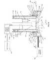
- FIG. 1illustrates a cross-sectional view of an embodiment employing a positioning system that receives and moves an electrical energy conducting element into engagement with the cornea according to aspects of the present invention.
- FIG. 2illustrates another cross-sectional view of the embodiment of FIG. 1 .
- FIG. 3Aillustrates an image of a cornea after energy has been applied.
- FIG. 3Billustrates another image of the cornea of FIG. 3A .
- FIG. 3Cillustrates an image of the cornea of FIG. 3A .
- FIG. 3Dillustrates another image of the cornea of FIG. 3A .
- FIG. 4illustrates an example of a coupling system for adjustably coupling an energy conducting element to an applicator housing according to aspects of the present embodiment.
- FIG. 5illustrates an automated adjustment system for adjustably coupling an energy conducting element to an applicator housing according to aspects of the present embodiment.
- FIG. 6illustrates a cross-sectional view of an embodiment that employs an electromechanical element to position an energy conducting element according to aspects of the present invention.
- FIG. 7illustrates a cross-sectional view of another embodiment that employs an electromechanical element to position an energy conducting element according to aspects of the present invention.
- FIG. 8illustrates a cross-sectional view of an embodiment that employs yet another electromechanical element to position an energy conducting element according to aspects of the present invention.
- FIG. 9illustrates a cross-sectional view of an embodiment that draws the cornea into contact with the energy conducting element according to aspects of the present invention.
- FIG. 10illustrates a cross-sectional view of an embodiment employing a positioning system that receives and moves an optical energy conducting element into engagement with the cornea according to aspects of the present invention.
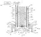
- FIG. 1shows an applicator 100 that includes a housing 110 and an energy conducting element 111 , which extend from a proximal end 100 A to a distal end 100 B.
- the energy conducting element 111is positioned within a passageway 110 A which extends longitudinally through the housing 110 . Any number of bearings 110 B, or similar guiding structures, may be employed to keep the energy conducting element 111 substantially centered within the passageway 110 A.
- An electrical energy source 120is operably connected to the energy conducting element 111 at the distal end 100 B, for example, via conventional conducting cables.
- the electrical energy source 120may include a microwave oscillator for generating microwave energy.
- the oscillatormay operate at a microwave frequency range of 500 MHz to 3000 MHz, and more specifically at a frequency of around 915 MHz which provides safe use of the energy conducting element 111 .
- microwave frequenciesit is contemplated that any frequency, e.g., including microwave, radio-frequency (RF), etc., may be employed.
- RFradio-frequency
- embodimentsmay employ radiation having, but not limited to, a frequency between 10 MHz and 300 GHz.
- Operation of the energy source 120causes energy to be conducted through the energy conducting element 111 to the distal end 100 B.
- the applicator 100may be employed to apply energy to the cornea 2 of the eye 1 which is positioned at the distal end 100 B.
- the distal end 100 Bis positioned over the cornea 2 by a positioning system 200 .
- the positioning system 200provides support for the applicator 100 so that the energy conducting element 111 can be operated to deliver energy to targeted areas of the cornea 2 .
- the positioning system 200includes an attachment element 210 which receives the applicator housing 110 . Meanwhile, the attachment element 210 can be fixed to a portion of the eye surface 1 A, such as the area surrounding the portion of the cornea 2 being treated.
- the attachment element 210situates the applicator 100 in a stable position for delivering energy to the cornea 2 .
- the attachment element 210 of the positioning system 200may have a substantially annular structure defining a central passageway 211 through which the applicator housing 110 can be received and the cornea 2 can be accessed.
- an outer diameter of the annular structuremay range from approximately 18 mm to 23 mm while an inner diameter may range from approximately 11 mm to 15 mm to accommodate aspects of the eye 1 and the cornea 2 .
- the attachment element 210may be attached to portions of the eye surface 1 A by creating a vacuum connection with the eye surface 1 A.
- the attachment element 210 of FIG. 1acts as a vacuum ring that includes an interior channel 212 which is operably connected to a vacuum source 140 via connection port 217 .
- the attachment element 210also includes a plurality of openings 216 which open the interior channel 212 to the eye surface 1 A.
- the attachment element 210may be formed from a biocompatible material such as a titanium alloy or the like.
- FIG. 2illustrates a cross-sectional view of the attachment element 210 , including the central passageway 211 , the interior channel 212 , the plurality of openings 216 , and the connection port 217 .
- FIG. 2also shows the housing 110 being received within the central passageway 211 .
- the openings 216When the openings 216 are positioned in contact with the eye surface 1 A and the vacuum source 140 is activated to create a near vacuum or low pressure within the interior channel 212 , the openings 216 operate to suction the attachment element 210 and the eye surface 1 A together.
- the bottom surface 213 of the attachment element 210may be contoured to fit the shape of the eye more closely.
- the vacuum source 140may be a syringe, but the vacuum source 140 may be any manual or automated system that creates the appropriate amount of suction between the attachment element 210 and the eye surface 1 A.
- the attachment element 210can be stably attached to the eye surface 1 A, the attachment element 210 can be detached by removing the vacuum source 140 and equalizing the pressure in the interior channel 212 with the exterior environment.
- the applicator 100When applying energy to the cornea 2 , the applicator 100 may be centered, for example, over the pupil 3 , which is generally coincident with a center portion 2 C of the cornea 2 .
- the positioning system 200may provide an additional receiving element that is coupled to the attachment element 210 and movable relative to the attachment element 210 .
- the receiving elementreceives the energy conducting element 111 and can be moved to adjust the position of the energy conducting element 111 with respect to the attachment element 210 and the cornea 2 .
- the energy conducting element 111can be accurately positioned over the cornea 2 via the position system.
- the positioning system 200enables the energy conducting element 111 to apply energy to desired areas of the cornea 2 , for example centered about the pupil 3 , to achieve the desired reshaping of the cornea 2 .
- the energy conducting element 111can deliver energy to targeted areas of collagen fibers in a mid-depth region 2 B of the cornea 2 to shrink the collagen fibers according to a predetermined pattern and reshape the cornea 2 in a desired manner, thereby improving vision through the eye 1 .
- a contribution to the corneal reshapingcomes from the contraction of the collagen fibrils found in the upper third of the corneal stroma, lying approximately 75-150 microns below the corneal, i.e., epithelial, surface 2 A.
- the electrical energy conducting element 111includes two microwave conductors 111 A and 111 B, which extend from the proximal end 100 A to the distal end 100 B of the applicator 100 .
- the conductor 111 Amay be a substantially cylindrical outer conductor
- the conductor 111 Bmay be a substantially cylindrical inner conductor that extends through an inner passage extending through the outer conductor 111 A.
- the outer conductor 111 Ahas a substantially tubular shape.
- the inner and the outer conductors 111 A and 111 Bmay be formed, for example, of aluminum, stainless steel, brass, copper, other metals, metal-coated plastic, or any other suitable conductive material.
- the outer conductor 111 Ahas a distal surface 111 E and the inner conductor 111 B has a distal surface 111 F.
- the distal surfaces 111 E and 111 F, or portions thereof,provide an eye contact portion that can be applied against the cornea 2 , as shown in FIG. 1 .
- the distal surface 111 E of the outer electrode 111 Amay extend past the distal surface 111 F of the inner electrode 111 B, or alternatively, the position of the distal surface 111 F may be in a recessed position with respect to the distal surface 111 E.
- a substantially annular gap 111 C of a selected distanceis defined between the conductors 111 A and 111 B.
- the annular gap 111 Cextends from the proximal end 100 A to the distal end 100 B.
- a dielectric material 111 Dmay be used in portions of the annular gap 111 C to separate the conductors 111 A and 111 B.
- the distance of the annular gap 111 C between conductors 111 A and 111 Bdetermines the penetration depth of microwave energy into the cornea 2 according to established microwave field theory.
- the microwave conducting element 111receives, at the proximal end 100 A, the electrical energy generated by the electrical energy source 120 , and directs microwave energy to the distal end 111 B, where the cornea 2 is positioned in accordance with the positioning system 200 .
- the outer diameter of the inner conductor 111 Bis preferably larger than the pupil 3 , over which the applicator 100 is centered.
- the outer diameter of the inner conductor 111 Bmay be selected to achieve an appropriate change in corneal shape, i.e. keratometry, induced by the exposure to microwave energy.
- the outer diameter of the inner electrode 111 Bdetermines the diameter across which the refractive change to the cornea 2 is made.
- the inner diameter of the outer conductor 111 Amay be selected to achieve a desired gap between the conductors 111 A and 111 B.
- the outer diameter of the inner conductor 111 Branges from about 4 mm to about 10 mm while the inner diameter of the outer conductor 111 A ranges from about 4.1 mm to about 12 mm.
- the annular gap 111 Cmay be sufficiently small, e.g., in a range of about 0.1 mm to about 2.0 mm, to minimize exposure of the endothelial layer of the cornea (posterior surface) to elevated temperatures during the application of energy by the applicator 100 .
- a controller 130may be employed to selectively apply the energy any number of times according to any predetermined or calculated sequence.
- the energymay be applied for any length of time.
- the magnitude of energy being appliedmay also be varied. Adjusting such parameters for the application of energy determines the extent of changes that are brought about within the cornea 2 .
- the systemattempts to limit the changes in the cornea 2 to an appropriate amount of shrinkage of collagen fibrils in a selected region.
- the microwave energymay be applied with low power (of the order of 40 W) and in long pulse lengths (of the order of one second). However, other systems may apply the microwave energy in short pulses.
- the microwave energymay be applied in pulses having a higher power in the range of 500 W to 3 KW and a pulse duration in the range of about 10 milliseconds to about one second.
- each of the conductors 111 A and 111 Bmay be covered with an electrical insulator to minimize the concentration of electrical current in the area of contact between the corneal surface (epithelium) 2 A and the conductors 111 A and 111 B.
- the conductors 111 A and 111 B, or at least a portion thereofmay be coated with a material that can function both as an electrical insulator as well as a thermal conductor.
- a dielectric material 111 Dmay be employed along the distal end 100 B of the applicator 100 to protect the cornea 2 from electrical conduction current that would otherwise flow into the cornea 2 via conductors 111 A and 111 B.
- the dielectric material 111 Dis positioned between the conductors 111 A and 111 B and the cornea 2 .
- the distal surfaces 111 E and 111 F of the conductors 111 A and 111 Binclude a dielectric material 111 D.
- the dielectric material 111 Dmay be sufficiently thin to minimize interference with microwave emissions and thick enough to prevent superficial deposition of electrical energy by flow of conduction current.
- the dielectric material 111 Dmay be a biocompatible material, such as Teflon®, deposited to a thickness of about 0.002 inches.
- an interposing layersuch as the dielectric material 111 D
- the dielectric material 111 Dmay be omitted and electrical energy in the microwave or radio frequency (RF) band may be applied directly.
- RFradio frequency
- a similar electrically insulating material 111 Hmay also be employed on the outer surface of the outer electrode 111 A.
- the distal end 100 B of the applicator 100 as shown in FIG. 1is positioned by the positioning system 200 at the corneal surface 2 A.
- the applicator 100positions the energy conducting element 111 to make direct contact with the corneal surface 2 A.
- the distal surfaces 111 E and 111 F of the conductors 111 A and 111 B, respectively,are positioned against the corneal surface 2 A.
- the positioning of the conductors 111 A and 111 Bhelps ensure that the pattern of microwave energy in the corneal tissue has substantially the same shape and dimension as the gap 111 C between the two microwave conductors 111 A and 111 B.
- the applicator 100may also employ a coolant system 112 that selectively applies coolant to the corneal surface 2 A to minimize heat-related damage to the corneal surface 2 A during thermokeratoplasty and to determine the depth of energy delivered below the corneal surface 2 A to the mid-depth region 2 B.
- a coolant systemenables the energy conducting element 111 to be placed into direct contact with the corneal surface 2 A without causing heat-related damage.
- the coolantmay also be applied after the application of energy to preserve, or “set,” the desired shape changes by eliminating further presence of energy and preventing further changes to the new corneal shape. Examples of such a coolant system are described in U.S. application Ser. No. 11/898,189, filed Sep.
- the coolant delivery system 112 as well as a coolant supply 113may be positioned within the annular gap 111 C.
- FIG. 1may illustrate one coolant delivery system 112
- the applicator 100may include a plurality of coolant delivery systems 112 arranged circumferentially within the annular gap 111 C.
- the coolant supply 113may be an annular container that fits within the annular gap 111 C, with the coolant delivery element 112 having a nozzle structure 112 A extending downwardly from the coolant supply 113 and an opening 112 B directed toward the distal end 100 B.
- the coolantmay be a liquid cryogen, such as tetrafluorothane.
- the coolantmay be a cool gas, such as nitrogen gas, e.g., blowoff from a liquid nitrogen source.
- the coolant system 112is operated, for example, with the controller 130 to deliver pulses of coolant in combination with the delivery of energy to the cornea 2 .
- applying the coolant in the form of pulsescan help prevent the creation of a fluid layer between the conductors 111 A and 111 B and the corneal surface 2 A that interferes with the delivery of energy from the energy conducting electrode 111 .
- the short pulses of coolantmay evaporate from the corneal surface 2 A or may be removed, for example, by a vacuum (not shown) before the application of the microwave energy.
- the presence of a fluid layermay disadvantageously cause a less desirable circle-shaped microwave energy pattern in the cornea 2 with a diameter less than that of the inner conductor 111 B. Therefore, to achieve a desired microwave pattern in some embodiments, a substantial flow of coolant or a cooling layer does not exist over the corneal surface 2 A during the application of energy to the cornea 2 .
- the coolantmay actually be a cool gas, rather than a liquid coolant.
- heat sinksmay also be employed to direct heat away from the corneal surface 2 A and reduce the temperature at the surface 2 A.
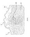
- FIGS. 3A-Dillustrate an example of the effect of applying energy to corneal tissue with a system for applying energy, such as the system illustrated in FIG. 1 .
- FIGS. 3A and 3Billustrate high resolution images of the cornea 2 after energy has been applied.
- a lesion 4extends from the corneal surface 3 A to a mid-depth region 3 B in the corneal stroma 2 D.
- the lesion 4is the result of changes in corneal structure induced by the application of energy as described above. These changes in structure result in an overall reshaping of the cornea 2 . It is noted that the application of energy, however, has not resulted in any heat-related damage to the corneal tissue.
- FIGS. 3A and 3Billustrate histology images in which the tissue shown in FIGS. 3A and 3B has been stained to highlight the structural changes induced by the energy.
- FIGS. 3C and 3Dillustrate histology images in which the tissue shown in FIGS. 3A and 3B has been stained to highlight the structural changes induced by the energy.
- the difference between the structure of collagen fibrils in the mid-depth region 2 B where energy has penetrated and the structure of collagen fibrils outside the region 2 Bis clearly visible.
- the collagen fibrils outside the region 2 Bremain generally unaffected by the application of energy, while the collagen fibrils inside the region 2 B have been rearranged and form new bonds to create completely different structures.
- the corneal areasexperience a thermal transition to achieve a new state.
- the embodiments described hereinprovide a system and method by which the application of energy can accurately and precisely provide the changes in corneal shape that provide the desired improvements in the eye. Unlike other approaches, the embodiments provide consistent and reproducible results, especially to enable the eye therapy to be used in a clinical setting.
- the energy pattern applied by the energy conducting element 111may be affected by an intermediate fluid layer that interferes with the contact between the energy conducting element 111 and the corneal surface 2 A.
- the application of energy to the cornea 2depends in part on the position of the distal surfaces 111 E and 111 F relative to the corneal surface 2 A.
- embodimentsensure that the distal surfaces 111 E and 111 F are positioned to make contact with the corneal surface 2 A. In this way, the relationship between the energy conducting element 411 and the cornea 2 is more definite and the resulting delivery of energy is more predictable and accurate.
- sufficient contactis determined by causing an observable amount of flattening, or applanation, of the cornea.
- the applanationprovides a constant and uniform pressure against the corneal surface 2 A.
- the applicator 100can position the energy conducting element 111 against the corneal surface 2 A so that the distal surface 111 E of the outer electrode 111 A and the distal surface 111 F of the inner electrode 111 B flattens the cornea 2 .
- the distal surfaces 111 E and 111 F, or portions thereof, in contact with the corneal surface 2 Aare substantially flat, it is understood that the surfaces 111 E and 111 F may be shaped, e.g. contoured, in other ways to cause the desired contact. As shown in FIG.
- the inner edge of the distal surface 111 E of the outer electrode 111 Amay be beveled, or otherwise shaped, to minimize any pinching of the cornea 2 that may occur between the outer electrode 111 A and the inner electrode 111 B when the distal surfaces 111 E and 111 F are applied against the cornea 2 .
- the applanation described hereinadds precision and accuracy to the eye therapy procedure, particularly by improving electrical and thermal contact between the distal surfaces 111 E and 111 F and the corneal surface 2 A.
- the housing 110 and the positioning system 200combine to keep the distal surfaces 111 E and 111 F in contact with the corneal surface 2 A and maintain the applanation of the cornea 2 as energy is delivered via the energy conducting element 111 .
- the housing 110 and the positioning system 200combine to enable reproducible and predictable contact between the distal surfaces 111 E and 111 F and the corneal surface 2 A.
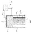
- a first coupling system 114may be employed to couple the housing 110 to the attachment element 210 of the positioning system 200 . Once the housing 110 is guided fully into the attachment 210 , the first coupling system 114 prevents the housing 110 from moving relative to the attachment element 210 along the Z-axis shown in FIG. 1 .
- the first coupling system 114may include connecting elements 114 A, which extend transversely from the attachment element 210 into cavities 114 B in the applicator housing 110 .
- the applicator 110is guided into the passageway 211 until the cavities 114 B reach and engage the connecting elements 114 A.
- the connecting elements 114 Amay be retractable to facilitate removal of the housing 110 from the attachment element 210 .
- the connecting elements 114 Amay be rounded structures that extend from the housing 110 on springs (not shown).
- the first coupling system 114may employ other techniques, e.g. mechanically interlocking or engaging structures, for coupling the housing 110 to the attachment element 210 .
- the central passageway 211 of the attachment element 210may have a threaded wall which receives the housing 110 in threaded engagement.
- the housing 110may be screwed into the attachment element 210 .
- the applicatorcan then be rotated about the Z-axis and moved laterally along the Z-axis to a desired position relative to the cornea 2 . Stops may be included on the attachment element 210 to determine the target position of the applicator 100 in the passageway 211 .
- a second adjustable coupling system 115may be employed to couple the energy conducting element 110 to the housing 110 .
- the second coupling system 115prevents the energy conducting element 111 from moving relative to the housing 110 along the Z-axis. For example, as illustrated in FIG.
- the second coupling system 115may include a connecting element 115 A, such as a pin-like structure, which is positioned along the housing 110 and extends inwardly from the housing 110 into a cavity of a receiving structure 115 B on the energy conducting element 111 .
- the second coupling system 115may employ other techniques for coupling the energy conducting element 111 to the housing 110 .
- the energy conducting element 111may be simply fastened or bonded to the inner walls of the housing 110 according to conventional methods.
- the electrical conducting element 111 , the housing 110 , and the attachment element 210are all fixed relative to each other while the attachment element 210 is attached to the corneal surface 2 A. Accordingly, the energy conducting element 111 is able to apply constant pressure against the corneal surface 2 A and flatten the cornea 2 .
- the coupling systems 114 and 115reproducibly determines the position of the energy conducting element 111 with respect to the cornea 2 .
- the positions of the connecting element 115 A and/or the receiving structure 115 Bmay be adjustable to enable the energy conducting element 111 to occupy a selected position within the housing 110 and provide a desired amount of applanation.
- the connecting element 115 Amay be a threaded pin that is screwed into a corresponding threaded cavity 115 C in the receiving structure 115 B. Once the connecting element 115 A is fully screwed into the cavity 115 C, a head 115 E of the connecting element 115 A and the receiving structure 115 B are held against the housing 110 by sufficient contact and friction to prevent movement of the connecting element 111 A and the energy conducting element 111 along the Z-axis.
- the connecting element 115 Acan be positioned at various points in a slot, or opening, 115 D that extends along the Z-axis in the housing 110 . Therefore, the energy conducting element 111 can be moved to different positions along the Z-axis relative to the housing 110 , and the connecting element 115 A can be correspondingly moved in the slot 115 to be screwed into the receiving element 115 B and couple the energy conducting element 111 to the housing 110 .
- the ability to change the position of the energy conducting element 111 relative to the housing 110means that the position of the distal ends 111 E and 111 F of the energy conducting element 111 relative to the corneal surface 2 A can be changed.
- the amount of pressure on the cornea 2can be adjusted to provide a particular amount of applanation.
- the connecting element 115 Aremains in the same position relative to the housing 110 , the particular amount of applanation is reproducible.
- FIG. 5illustrates the movement of the energy conducting element 111 toward the cornea 2 within the housing 110 which is fixed relative to the cornea 2 with the attachment element 210 .
- adjusting the position of the energy conducting element 111 relative to the housing 110may be achieved manually, a more automated adjustment system 300 , as shown in FIG. 5 , can be employed to adjustably couple the energy conducting element 111 to the housing 110 .
- the adjustment system 300facilitates the accurate positioning of the energy conducting element 300 against the corneal surface 2 A.
- the applicator 100is guided into position within the passageway 211 of the attachment element 210 , and the adjustment system 300 can be easily operated to move the distal surfaces 111 E and 111 F of the energy conducting element 111 against the corneal surface 2 A.
- the adjustment system 300may be further connected to a user interface system 305 that accepts input from a user and correspondingly operates the adjustment system 300 .
- the user interface system 305may be a device with a keypad to receive input from a user.
- the keypadmay be part of a processing system, such as a conventional personal computer, with software to control the adjustment system 300 .
- the user interface system 305may be a device, such as a joystick, that receives instructions from the user through more mechanically oriented input.
- FIG. 5illustrates the downward movement of the energy conducting device 111 relative to the housing 110 and the positioning system 200 and into contact with the corneal surface 2 A.
- One or more stopsmay be employed to determine the extent of the downward movement of the energy conducting element 111 against the cornea 2 .
- the energy conducting device 111may applied to cause applanation of the cornea 2 , similar to the applanation shown in FIG. 1 .
- the applanationindicates that sufficient contact has been established between the energy conducting device 111 , i.e., the distal contact surfaces 111 E and 111 F, and the corneal surface 2 A.
- a physical measurement device 340may be employed with the adjustment system 300 to measure the amount of pressure being applied by the distal surfaces 111 E and 111 F against the cornea 2 .
- the physical measurement device 340may be a strain gauge that is able to detect the deformation in the energy conducting element 111 caused by contact with the corneal surface 2 A. Therefore, the physical measurement device 340 indicates when the energy conducting element 111 has made sufficient contact with the corneal surface 2 A and is applying constant and uniform pressure. As a result, applanation is not necessary to receive an indication that sufficient contact has been established with the cornea 2 .
- the physical measurement device 340also enables the application of a certain pressure to be reliably and accurately reproduced.
- the adjustment system 300may be an electromechanical system 310 that includes a motor 311 connected to a configuration 312 of one or more gears 313 coupled to the housing 110 .
- the gears 313in turn engage corresponding teeth 314 that are aligned parallel with the Z-axis and extend outwardly from the energy conducting element 111 .
- operation of the motor 311via a user interface system 305 , causes rotation of the gears 313 and corresponding movement of the teeth 314 and thus the energy conducting element 111 along the Z-axis.
- a safety mechanism 116may be employed as shown in FIG. 6 .
- the energy conducting element 111can move toward or against the corneal surface 2 A until a stop 116 B, which extends outwardly from, and moves with, the energy conducting element 111 , makes contact with a corresponding stop extending inwardly from the housing 110 .
- the stop 116 Ais positioned to block further movement of the block 116 B and the energy conducting element 111 past a particular point along the Z-axis.
- FIG. 6shows a bearing 110 B that extends inwardly from the housing 110 and is positioned opposite the gear 113 to position the energy conducting element 111 within the passageway 110 A of the housing 110 .
- a spring 110 Gmay be employed to bias the energy conducting element 111 toward the gear 113 .
- any number of such bearings, or guiding elements, 110 Bmay be employed within the housing 110 .
- springs 110 Gmay be employed with any of these bearings 110 B.
- the electromechanical system 310may be applied to cause applanation of the cornea 2 to ensure sufficient contact has been established between the energy conducting device 111 , i.e., the distal contact surfaces 111 E and 111 F, and the corneal surface 2 A.
- a physical measurement device 340such as a strain gauge, may be employed with the electromechanical system 310 to measure the amount of pressure being applied by the distal surfaces 111 E and 111 F against the cornea 2 .
- the physical measurement device 340measures the amount of compression and the measurement can be translated into the pressure being applied to the cornea 2 .
- a threshold pressure measurement corresponding to a desired amount of contact between the energy conducting electrode 111 and the cornea 2can be determined.
- the threshold valuecorresponds to the first instance of constant and uniform application of pressure on the cornea 2 . Therefore, once the measured pressure reaches this threshold value, further downward movement of the energy conducting element 111 against the corneal surface 2 A is not necessary. As such, causing applanation of the cornea 2 is also not necessary.
- the physical measurement device 340also enables the application of a certain pressure to be reliably and accurately reproduced.
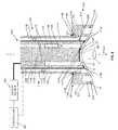
- FIG. 7illustrates another adjustment system 300 that employs an electromechanical system 320 including a motor 321 connected to an alternative configuration 322 of one or more gears 323 connected to the housing 110 .
- FIG. 7demonstrates that a variety of gear configurations may be employed according to aspects of the present invention.
- a gear configurationmay be selected, for instance, according to the desired geometry of the assembled system.
- the configuration 322 in FIG. 7includes gears 323 A which cause a worm 323 B to rotate about an axis parallel with the Z-axis.
- the worm 323 Bwhich is operably coupled to the housing 110 engages teeth 324 operably coupled to the energy conducting element 111 .
- the teeth 324are aligned parallel to the Z-axis and the rotation of the worm 323 B causes the teeth 324 and the energy conducting element 111 to move along the Z-axis.
- the embodiment of FIG. 7may employ a safety mechanism 116 , as described previously.
- any number of such bearings, or guiding elements, 110 Bmay be employed within the housing 110 .
- additional intermediate structuresmay be employed to couple the energy conducting element 111 to the housing 110 .
- the teeth 324extend outwardly from an intermediate structure, or cylindrical structure, 117 .
- the energy conducting element 111is enclosed in a chamber 117 A defined by the cylindrical structure 117 , so that movement of the cylindrical structure 117 causes corresponding movement of the energy conducting element 111 .
- the energy conducting element 111may be clipped into, or otherwise coupled or attached to, the cylindrical structure 117 .
- any connections to the energy conducting element 111can be made through the wall(s) of the cylindrical structure 117 .
- the energy conducting element 111is not required to accommodate specific aspects of the adjustment system 300 .
- the energy conducting element 111does not have to include the teeth 324 , as the teeth 324 are provided with the cylindrical structure 117 .
- the applicator housing 110is more easily compatible with different energy conducting elements 111 . It is therefore contemplated that embodiments may include reusable applicator housings with replaceable interchangeable energy conducting elements 111 .
- the electromechanical system 330 shown in FIG. 8employs a piezoelectric system.
- a piezoelectric element, or material, 331couples the energy conducting element 111 to the housing 110 and is connected to an electrical source 332 .
- the electrical source 332is operated by the user interface system 305 to apply an electric field to the piezoelectric element 331 , the piezoelectric element 331 expands or contracts along the Z-axis depending on the electric field.
- the energy conducting element 111is coupled to the piezoelectric element 331 , as shown in FIG. 8 , the energy conducting element 111 is correspondingly moved in along the Z-axis.
- the applicator 100in alternative embodiments may draw the cornea 2 into desired contact with the energy conducting element 111 .
- the energy conducting element 111may be positioned over the cornea 111 .
- a vacuum source 350is operated by a controller 130 to create a vacuum, or near vacuum, within the applicator 100 and draw or suction the corneal surface 2 A into contact with the distal surfaces 111 E and 111 F.
- a physical measurement device 340may be employed to indicate to the controller 130 that sufficient contact has been established.
- the strain gaugemeasures how much the energy conducting element 111 is being compressed as the cornea is drawn against the distal surfaces 111 E and 111 F by increasing suction levels from the vacuum source 350 .
- the controller 130maintains the level of vacuum to keep the cornea 2 in sufficient contact with the energy conducting electrode 111 .
- the controlled vacuum source 350may be used in combination with an adjustment system that can position the energy conducting electrode 111 over the cornea 2 before the vacuum source 350 is operated.
- an applicator 400that includes a housing 410 and an optical energy conducting element 411 .
- the optical energy conducting element 411passes through a passageway 410 A in the housing 410 and is operably connected to an optical energy source 420 , for example, via conventional optical fiber. Any number of bearings, or similar guiding structures, 410 B may be employed to position the optical energy conducting element 411 within the housing 410 .
- the optical energy source 420may include a laser, a light emitting diode, or the like.
- the optical energy conducting element 411extends to a distal end 400 B from a proximal end 400 A, where it is operably connected with the optical source 420 .
- the optical energy conducting element 411includes an optical fiber 411 A.
- the optical fiber 411 Areceives optical energy from the optical energy source 420 at the proximal end 400 A and directs the optical energy to the distal end 400 B, where the cornea 2 of an eye 1 is positioned.
- a controller 430may be operably connected to the optical energy source 420 to control the delivery, e.g. timing, of the optical energy to the optical conducting element 411 .
- the optical energy conducting element 411irradiates the cornea 2 with the optical energy and delivers energy for appropriately shrinking collagen fibers in the mid-depth region 2 B of the cornea 2 .
- the optical conducting element 411may include an optical focus element 411 B, such as a lens, to focus the optical energy and to determine the pattern of irradiation for the cornea 2 .
- the distal end 400 B of the optical conducting element 411e.g., the optical focus element 411 B, may include an eye contact surface 411 C that makes constant and uniform contact with the cornea surface 2 A.
- the application of energy to the cornea 2may depend in part on the position of the optical conducting element 411 relative to the corneal surface 2 A.
- embodimentsensure that the eye contact surface 411 C is positioned to make contact with the corneal surface 2 A.
- the relationship between the optical conducting element 411 and the cornea 2is more definite and the resulting delivery of energy is more predictable.
- sufficient contactis determined by causing an observable amount of flattening, or applanation, of the cornea, as shown in FIG. 10 .
- a physical measurement devicesimilar to device 340 above, may be employed to measure the amount of pressure being applied against the corneal surface 2 A, so that applanation is not necessary to ensure that the eye contact surface 411 C is in constant and uniform contact with the corneal surface 2 A.
- the applicator 400may also employ a coolant system 412 that selectively applies coolant to the corneal surface 2 A.
- the coolant delivery system 412as well as a coolant supply 413 may be positioned adjacent to the optical energy conducting element 411 .
- the coolant system 412may be operated, for example, with the controller 430 to deliver pulses of coolant in combination with the delivery of energy to the cornea 2 . Applying the coolant in the form of pulses can help minimize the creation of a fluid layer between the optical energy conducting element 411 and the corneal surface 2 A providing the advantages described previously.
- the applicator 400 and the optical energy conducting element 411are positioned over the cornea 2 by the positioning system 200 to deliver the optical energy to targeted areas of the cornea 2 .
- the positioning system 200is employed in the same manner similar to the previous embodiments. In particular, the positioning system 200 places the distal end 400 B of the applicator 400 in a stable position over the cornea 2 .
- a first coupling system 414may be employed to couple the housing 410 to the attachment element 210 of the positioning system 200 .
- the first coupling system 414may include connecting elements 414 A on the attachment element 210 that are received into cavities 414 B on the applicator housing 410 . Once the housing 410 is fully received into the attachment 210 , the first coupling system 414 prevents the housing 410 from moving relative to the attachment element 210 along the Z-axis.
- a second coupling system 415is employed to couple the optical energy conducting element 410 to the housing 410 .
- the second coupling system 415prevents the energy conducting element 411 from moving relative to the housing 410 along the Z-axis.
- the second coupling system 415may include a connecting element 415 A, such as a pin-like structure, which extends inwardly from the housing 410 into a cavity of a receiving structure 415 B on the energy conducting element 411 .
- the second coupling system 415may employ other techniques for coupling the energy conducting element 411 to the housing 410 .
- the electrical conducting element 411 , the housing 410 , and the attachment element 210are all fixed relative to each other while the attachment element 210 is attached to the corneal surface 2 A. Accordingly, the optical conducting element 411 is able to apply constant pressure against the corneal surface 2 A.
- an automated adjustment systemmay be employed in a system using an optical energy conducting element 411 .
- the automated adjustment systemcouples the optical energy conducting element 411 to the applicator housing 410 , but allows electromechanically controlled movement of the optical energy conducting element 411 relative to the housing 410 along the Z-axis.
- the optical energy conducting element 411may be moved into contact with the corneal surface 2 A to provide a flattening pressure on the cornea.
- embodiments according to aspects of the present inventionprovide a system and method for applying a thermokeratoplasty applicator to the cornea.
- embodimentsprovide a system and method for positioning the applicator over the cornea so that the applicator can cause the desired amount of flattening of a cornea and improve vision through the cornea.
- embodimentsmay provide the applicator with an eye contact surface that is moved manually, electromechanically, etc. into contact with the corneal surface to physically flatten the cornea as energy is also delivered to the cornea.
- embodimentsprovide an improved system and method that facilitates handling and positioning of the applicator to achieve the desired reshaping of a cornea.
- the inventionis not limited thereto.
- the present inventionmay be changed, modified and further applied by those skilled in the art.
- the applicators 200 and 400 in the examples aboveare separate elements received into the positioning system 200
- the applicator 200 or 400 and the positioning system 200may be combined to form a more integrated device.
- embodimentsmay include an integrated applicator housing and positioning system that receives and positions an energy conducting element against the cornea.
- the attachment element 210 in the embodiments abovemay be a vacuum device which is auctioned to the eye surface, it is contemplated that other types of attachment elements may be employed.
- the attachment elementmay be fixed to other portions of the head. Therefore, this invention is not limited to the detail shown and described previously, but also includes all such changes and modifications.
Landscapes
- Health & Medical Sciences (AREA)
- Surgery (AREA)
- Life Sciences & Earth Sciences (AREA)
- Engineering & Computer Science (AREA)
- Animal Behavior & Ethology (AREA)
- Veterinary Medicine (AREA)
- Nuclear Medicine, Radiotherapy & Molecular Imaging (AREA)
- Public Health (AREA)
- Biomedical Technology (AREA)
- Heart & Thoracic Surgery (AREA)
- General Health & Medical Sciences (AREA)
- Otolaryngology (AREA)
- Molecular Biology (AREA)
- Medical Informatics (AREA)
- Physics & Mathematics (AREA)
- Ophthalmology & Optometry (AREA)
- Plasma & Fusion (AREA)
- Electromagnetism (AREA)
- Vascular Medicine (AREA)
- Radiation-Therapy Devices (AREA)
- Eye Examination Apparatus (AREA)
- Surgical Instruments (AREA)
Abstract
Description
Claims (31)
Priority Applications (6)
| Application Number | Priority Date | Filing Date | Title |
|---|---|---|---|
| US12/018,457US8409189B2 (en) | 2008-01-23 | 2008-01-23 | System and method for reshaping an eye feature |
| EP08799473AEP2240235A4 (en) | 2008-01-23 | 2008-09-11 | System and method for reshaping an eye feature |
| US12/209,123US8348935B2 (en) | 2008-01-23 | 2008-09-11 | System and method for reshaping an eye feature |
| PCT/US2008/076062WO2009094049A1 (en) | 2008-01-23 | 2008-09-11 | System and method for reshaping an eye feature |
| PCT/US2009/031718WO2009094470A1 (en) | 2008-01-23 | 2009-01-22 | System and method for reshaping an eye feature |
| EP09704233AEP2244651A4 (en) | 2008-01-23 | 2009-01-22 | System and method for reshaping an eye feature |
Applications Claiming Priority (1)
| Application Number | Priority Date | Filing Date | Title |
|---|---|---|---|
| US12/018,457US8409189B2 (en) | 2008-01-23 | 2008-01-23 | System and method for reshaping an eye feature |
Related Child Applications (1)
| Application Number | Title | Priority Date | Filing Date |
|---|---|---|---|
| US12/209,123Continuation-In-PartUS8348935B2 (en) | 2008-01-23 | 2008-09-11 | System and method for reshaping an eye feature |
Publications (2)
| Publication Number | Publication Date |
|---|---|
| US20090187184A1 US20090187184A1 (en) | 2009-07-23 |
| US8409189B2true US8409189B2 (en) | 2013-04-02 |
Family
ID=40877044
Family Applications (1)
| Application Number | Title | Priority Date | Filing Date |
|---|---|---|---|
| US12/018,457Expired - Fee RelatedUS8409189B2 (en) | 2008-01-23 | 2008-01-23 | System and method for reshaping an eye feature |
Country Status (3)
| Country | Link |
|---|---|
| US (1) | US8409189B2 (en) |
| EP (2) | EP2240235A4 (en) |
| WO (2) | WO2009094049A1 (en) |
Cited By (14)
| Publication number | Priority date | Publication date | Assignee | Title |
|---|---|---|---|---|
| US20090024117A1 (en)* | 2007-07-19 | 2009-01-22 | Avedro, Inc. | Eye therapy system |
| US20090187173A1 (en)* | 2008-01-23 | 2009-07-23 | David Muller | System and method for reshaping an eye feature |
| US20100016849A1 (en)* | 2008-07-16 | 2010-01-21 | Avner Rosenberg | Rf electrode for aesthetic and body shaping devices and method of using same |
| US20100185192A1 (en)* | 2008-11-11 | 2010-07-22 | Avedro, Inc. | Eye therapy system |
| US20100256705A1 (en)* | 2009-04-02 | 2010-10-07 | Avedro, Inc. | Eye therapy system |
| US20100256626A1 (en)* | 2009-04-02 | 2010-10-07 | Avedro, Inc. | Eye therapy system |
| US20100280509A1 (en)* | 2009-04-02 | 2010-11-04 | Avedro, Inc. | Eye Therapy System |
| US8652131B2 (en) | 2007-07-19 | 2014-02-18 | Avedro, Inc. | Eye therapy system |
| US10219948B2 (en) | 2016-02-24 | 2019-03-05 | Perfect Ip, Llc | Ophthalmic laser treatment system and method |
| US10575986B2 (en) | 2012-03-29 | 2020-03-03 | Cxl Ophthalmics, Llc | Ophthalmic treatment solution delivery devices and delivery augmentation methods |
| US10729716B2 (en) | 2012-03-29 | 2020-08-04 | Cxl Ophthalmics, Llc | Compositions and methods for treating or preventing diseases associated with oxidative stress |
| US10932864B2 (en) | 2018-11-28 | 2021-03-02 | Rxsight, Inc. | Tracking-based illumination control system |
| US11013593B2 (en) | 2018-12-02 | 2021-05-25 | Rxsight, Inc. | Light adjustable lens tracking system and method |
| US11033429B2 (en) | 2010-09-30 | 2021-06-15 | Cxl Ophthalmics, Llc | Ophthalmic treatment device, system, and method of use |
Families Citing this family (3)
| Publication number | Priority date | Publication date | Assignee | Title |
|---|---|---|---|---|
| WO2017066620A1 (en) | 2015-10-16 | 2017-04-20 | Rynerson James M | Energetic device for treating an eye disorder |
| CN114945337A (en) | 2019-11-06 | 2022-08-26 | 因赛特福仪器公司 | Systems and methods for cutting tissue |
| JP2024520392A (en) | 2021-05-27 | 2024-05-24 | インサイトフル インストゥルメンツ, インコーポレイテッド | Systems and methods for dissecting tissue - Patents.com |
Citations (108)
| Publication number | Priority date | Publication date | Assignee | Title |
|---|---|---|---|---|
| US3776230A (en) | 1973-04-18 | 1973-12-04 | C Neefe | Method of rapidly reshaping the cornea to eliminate refractive errors |
| US4326529A (en) | 1978-05-26 | 1982-04-27 | The United States Of America As Represented By The United States Department Of Energy | Corneal-shaping electrode |
| US4381007A (en) | 1981-04-30 | 1983-04-26 | The United States Of America As Represented By The United States Department Of Energy | Multipolar corneal-shaping electrode with flexible removable skirt |
| US4490022A (en) | 1982-01-04 | 1984-12-25 | Reynolds Alvin E | Apparatus for corneal corrective techniques |
| US4546773A (en)* | 1981-01-23 | 1985-10-15 | Accutome, Inc. | Apparatus to measure conical thickness |
| US4712543A (en) | 1982-01-20 | 1987-12-15 | Baron Neville A | Process for recurving the cornea of an eye |
| US4743725A (en) | 1985-12-05 | 1988-05-10 | Skandinavisk Torkteknik Ab | Coaxial line microwave heating applicator with asymmetrical radiation pattern |
| US4796623A (en)* | 1987-07-20 | 1989-01-10 | The Cooper Companies, Inc. | Corneal vacuum trephine system |
| US4805616A (en) | 1980-12-08 | 1989-02-21 | Pao David S C | Bipolar probes for ophthalmic surgery and methods of performing anterior capsulotomy |
| US4881543A (en) | 1988-06-28 | 1989-11-21 | Massachusetts Institute Of Technology | Combined microwave heating and surface cooling of the cornea |
| US4891043A (en) | 1987-05-28 | 1990-01-02 | Board Of Trustees Of The University Of Illinois | System for selective release of liposome encapsulated material via laser radiation |
| US4943296A (en) | 1986-03-28 | 1990-07-24 | Life Technology Research Foundation | Robot for surgical operation |
| US4994058A (en) | 1986-03-19 | 1991-02-19 | Summit Technology, Inc. | Surface shaping using lasers |
| US5103005A (en) | 1989-07-21 | 1992-04-07 | Coors Biotech, Inc. | Method for recovery of riboflavin |
| US5171254A (en) | 1991-11-19 | 1992-12-15 | Sher Neal A | Eye fixation device |
| US5281211A (en) | 1989-06-07 | 1994-01-25 | University Of Miami, School Of Medicine, Dept. Of Ophthalmology | Noncontact laser microsurgical apparatus |
| US5332802A (en) | 1988-02-18 | 1994-07-26 | Autogenesis Technologies, Inc. | Human collagen processing and autoimplant use |
| US5370644A (en) | 1988-11-25 | 1994-12-06 | Sensor Electronics, Inc. | Radiofrequency ablation catheter |
| US5395385A (en)* | 1989-12-14 | 1995-03-07 | Corneal Contouring, Inc. | Apparatus for surgically re-profiling the cornea |
| US5437658A (en) | 1992-10-07 | 1995-08-01 | Summit Technology, Incorporated | Method and system for laser thermokeratoplasty of the cornea |
| US5461212A (en) | 1993-06-04 | 1995-10-24 | Summit Technology, Inc. | Astigmatic laser ablation of surfaces |
| US5490849A (en) | 1990-07-13 | 1996-02-13 | Smith; Robert F. | Uniform-radiation caustic surface for photoablation |
| US5586134A (en) | 1992-11-13 | 1996-12-17 | Cymer Laser Technologies | Excimer laser |
| US5618284A (en) | 1985-09-27 | 1997-04-08 | Sunrise Technologies | Collagen treatment apparatus |
| US5624456A (en)* | 1996-02-07 | 1997-04-29 | Hellenkamp; Johann F. | Automatic surgical device for cutting a cornea |
| US5634921A (en) | 1993-08-23 | 1997-06-03 | Hood; Larry | Method and apparatus for modifications of visual acuity by thermal means |
| US5658278A (en) | 1992-12-01 | 1997-08-19 | Cardiac Pathways, Inc. | Catheter for RF ablation with cooled electrode and method |
| US5766171A (en) | 1994-02-09 | 1998-06-16 | Keravision, Inc. | Electrosurgical procedure for the treatment of the cornea |
| US5779696A (en) | 1990-07-23 | 1998-07-14 | Sunrise Technologies International, Inc. | Method and apparatus for performing corneal reshaping to correct ocular refractive errors |
| US5814040A (en) | 1994-04-05 | 1998-09-29 | The Regents Of The University Of California | Apparatus and method for dynamic cooling of biological tissues for thermal mediated surgery |
| US5830139A (en) | 1996-09-04 | 1998-11-03 | Abreu; Marcio M. | Tonometer system for measuring intraocular pressure by applanation and/or indentation |
| US5873901A (en) | 1995-06-30 | 1999-02-23 | Space Vacuum Epitaxy Center University Of Houston | Treating retinal damage by implanting thin film optical detectors |
| US5885275A (en) | 1998-01-15 | 1999-03-23 | Diomed, Inc. | Medical spacing guide |
| US5910110A (en) | 1995-06-07 | 1999-06-08 | Mentor Ophthalmics, Inc. | Controlling pressure in the eye during surgery |
| US5919222A (en) | 1998-01-06 | 1999-07-06 | Medtronic Inc. | Adjustable medical electrode lead |
| US6033396A (en) | 1995-11-06 | 2000-03-07 | Huang; David | Apparatus and method for performing laser thermal keratoplasty with minimized regression |
| US6053909A (en) | 1998-03-27 | 2000-04-25 | Shadduck; John H. | Ionothermal delivery system and technique for medical procedures |
| US6104959A (en) | 1997-07-31 | 2000-08-15 | Microwave Medical Corp. | Method and apparatus for treating subcutaneous histological features |
| US6139876A (en) | 1995-04-26 | 2000-10-31 | Jozsef Ladanyi | Gel with increased oxygen content |
| US6149646A (en) | 1999-02-02 | 2000-11-21 | Linvatec Corporation | Monopolar tissue ablator |
| WO2000074648A2 (en) | 1999-06-04 | 2000-12-14 | Sunrise Technologies International, Inc. | Prevention of regression in refractive keratoplasty |
| US6161544A (en) | 1998-01-28 | 2000-12-19 | Keratoform, Inc. | Methods for accelerated orthokeratology |
| US6162210A (en) | 1998-08-06 | 2000-12-19 | Shadduck; John H. | Laser mediated treatments for presbyopia and hyperopia |
| US6293938B1 (en) | 1994-04-08 | 2001-09-25 | Summit Technology, Inc. | Photo-refractive keratectomy |
| US20010034502A1 (en)* | 2000-03-29 | 2001-10-25 | Moberg Sheldon B. | Methods, apparatuses, and uses for infusion pump fluid pressure and force detection |
| US6319273B1 (en) | 1999-12-16 | 2001-11-20 | Light Sciences Corporation | Illuminating device for treating eye disease |
| US6325792B1 (en) | 1991-11-06 | 2001-12-04 | Casimir A. Swinger | Ophthalmic surgical laser and method |
| US20020002369A1 (en) | 1993-08-23 | 2002-01-03 | Hood Larry L. | Method and apparatus for modifying visual acuity by moving a focal point of energy within a cornea |
| US6342053B1 (en) | 1990-07-23 | 2002-01-29 | Laser Biotech, Inc. | Apparatus for cornea reshaping |
| US20020013579A1 (en) | 1997-10-03 | 2002-01-31 | Thomas A. Silvestrini | Rotating electrosurgical blade for corneal reshaping |
| US20020035345A1 (en) | 1999-05-25 | 2002-03-21 | Beck Jon E. | Methods and apparatus for ocular iontophopesis |
| US6402739B1 (en) | 1998-12-08 | 2002-06-11 | Y-Beam Technologies, Inc. | Energy application with cooling |
| US20020077699A1 (en)* | 2000-09-08 | 2002-06-20 | Luigi Olivieri | Apparatus and method for corneal surgery |
| US6413255B1 (en) | 1999-03-09 | 2002-07-02 | Thermage, Inc. | Apparatus and method for treatment of tissue |
| US20020099363A1 (en) | 2001-01-23 | 2002-07-25 | Woodward Benjamin W. | Radiation treatment system and method of using same |
| US20020164379A1 (en) | 2000-06-29 | 2002-11-07 | Toru Nishihara | Oxygen-containing ophthalmic composition |
| US20030018255A1 (en) | 1997-10-31 | 2003-01-23 | Martin Roy W. | Method and apparatus for medical procedures using high-intensity focused ultrasound |
| US6520956B1 (en) | 1995-11-06 | 2003-02-18 | David Huang | Apparatus and method for performing laser thermal keratoplasty with minimized regression |
| US20030097130A1 (en) | 1997-09-04 | 2003-05-22 | Gerhard Muller | Electrode arrangement for electrothermal treatment of human or animal bodies |
| US6617963B1 (en) | 1999-02-26 | 2003-09-09 | Sri International | Event-recording devices with identification codes |
| US20030175259A1 (en) | 1998-03-09 | 2003-09-18 | Hamper Karageozian | Use of corneal hardening agents in enzymeorthokeratology |
| US20030216728A1 (en)* | 1996-01-05 | 2003-11-20 | Stern Roger A. | RF electrode assembly for handpiece |
| US20040002640A1 (en) | 2002-07-01 | 2004-01-01 | Luce David A. | Method for eliminating error in tonometric measurements |
| US20040001821A1 (en) | 2000-10-13 | 2004-01-01 | Silver David M. | Plasminogen activator to prevent corneal and subepithelial haze after laser vision correction surgery |
| US20040111086A1 (en) | 2002-12-09 | 2004-06-10 | Trembly B. Stuart | Feedback control of thermokeratoplasty treatments |
| US6749604B1 (en) | 1993-05-10 | 2004-06-15 | Arthrocare Corporation | Electrosurgical instrument with axially-spaced electrodes |
| US20040199158A1 (en) | 1993-08-23 | 2004-10-07 | Hood Larry L. | Method and apparatus for modifications of visual acuity by thermal means |
| US20040243160A1 (en) | 2003-05-27 | 2004-12-02 | Yichieh Shiuey, M.D. | System for cutting the cornea of an eye |
| US20050033202A1 (en) | 2001-06-29 | 2005-02-10 | Chow Alan Y. | Mechanically activated objects for treatment of degenerative retinal disease |
| US20050070977A1 (en) | 2003-04-28 | 2005-03-31 | Molina Sherry L. | Light and magnetic emitting mask |
| US20050183732A1 (en) | 1999-05-18 | 2005-08-25 | Edwards Stuart D. | Surgical weight control device |
| US20050197657A1 (en) | 2004-03-02 | 2005-09-08 | Goth Paul R. | Thermokeratoplasty system with a regulated power generator |
| US6946440B1 (en) | 1999-09-15 | 2005-09-20 | Dewoolfson Bruce H | Composition for stabilizing corneal tissue during or after orthokeratology lens wear |
| US20050287217A1 (en) | 2002-10-31 | 2005-12-29 | Galit Levin | Transdermal delivery system for water insoluble drugs |
| US7044945B2 (en) | 2001-03-30 | 2006-05-16 | Sand Bruce J | Prevention of regression in thermal ciliary muscle tendinoplasty |
| US20060135957A1 (en) | 2004-12-21 | 2006-06-22 | Dorin Panescu | Method and apparatus to align a probe with a cornea |
| US20060149343A1 (en) | 1996-12-02 | 2006-07-06 | Palomar Medical Technologies, Inc. | Cooling system for a photocosmetic device |
| US20060189964A1 (en) | 2004-05-07 | 2006-08-24 | Anderson Robert S | Apparatus and method to apply substances to tissue |
| US20060206110A1 (en) | 1996-01-05 | 2006-09-14 | Thermage, Inc. | Handpiece with RF electrode and non-volative memory |
| US7130835B2 (en) | 2002-03-28 | 2006-10-31 | Bausch & Lomb Incorporated | System and method for predictive ophthalmic correction |
| US20060254851A1 (en) | 2005-05-10 | 2006-11-16 | Phonak Ag | Replaceable microphone protective membrane for hearing devices |
| US7141049B2 (en) | 1999-03-09 | 2006-11-28 | Thermage, Inc. | Handpiece for treatment of tissue |
| WO2006128038A2 (en) | 2005-05-26 | 2006-11-30 | Ntk Enterprises, Inc. | Device, system, and method for epithelium protection during cornea reshaping |
| US20060287649A1 (en) | 1998-12-14 | 2006-12-21 | Ormsby Theodore C | Radio-frequency based catheter system and method for ablating biological tissues |
| US20070048340A1 (en) | 2005-08-31 | 2007-03-01 | Searete Llc, A Limited Liability Corporation Of The State Of Delaware | Multi step patterning of a skin surface |
| US20070055227A1 (en) | 2005-09-08 | 2007-03-08 | Refractec, Inc. | Probe used for an ocular procedure |
| US20070074722A1 (en) | 2005-09-21 | 2007-04-05 | Kurve Technology, Inc. | Medicament delivery control, monitoring, and reporting system and method |
| US20070114946A1 (en) | 2005-11-18 | 2007-05-24 | Xtreme Technologies Gmbh | Arrangement for the generation of short-wavelength radiation based on a gas discharge plasma and method for the production of coolant-carrying electrode housing |
| US20070123845A1 (en) | 2005-11-29 | 2007-05-31 | Holger Lubatschowski | Method and device for processing a workpiece |
| US20070161976A1 (en) | 2002-12-09 | 2007-07-12 | Trembly B S | Thermokeratoplasty systems |
| US20070179564A1 (en) | 2004-02-06 | 2007-08-02 | Harold Thomas W | Treatment of vision disorders using electrical, light, and/or sound energy |
| US20070203547A1 (en) | 2005-12-15 | 2007-08-30 | Costello Benedict J | Medical device identification |
| US7270658B2 (en) | 2000-05-12 | 2007-09-18 | Arthrocare Corporation | Systems and methods for electrosurgery |
| US20070244496A1 (en) | 1996-02-07 | 2007-10-18 | Hellenkamp Johann F | Automatic surgical device and control assembly for cutting a cornea |
| US20070244470A1 (en) | 2006-04-17 | 2007-10-18 | Sdgi Holdings, Inc. | Method and apparatus for embedding a transmitter into a tool, and a system for monitoring the tool |
| WO2007120457A2 (en) | 2006-04-13 | 2007-10-25 | Euclid Systems Corporation | Composition and method for stabilizing corneal tissue after refractive surgery |
| US20080015660A1 (en) | 2006-07-13 | 2008-01-17 | Priavision, Inc. | Method And Apparatus For Photo-Chemical Oculoplasty/Keratoplasty |
| US20080027328A1 (en) | 1997-12-29 | 2008-01-31 | Julia Therapeutics, Llc | Multi-focal treatment of skin with acoustic energy |
| US20090024117A1 (en) | 2007-07-19 | 2009-01-22 | Avedro, Inc. | Eye therapy system |
| US20090054879A1 (en) | 2007-08-23 | 2009-02-26 | Ntk Enterprises, Inc. | System and method for defining and controlling ltk and other surgical eye procedures to produce little or no stromal collagen shrinkage |
| US20090069798A1 (en) | 2007-07-19 | 2009-03-12 | David Muller | Eye therapy system |
| EP1561440B1 (en) | 2004-02-03 | 2009-04-08 | Iroc AG | Ophtalmological device |
| US20090149923A1 (en) | 2007-12-07 | 2009-06-11 | 21X Corporation Dba Priavision, Inc. | Method for equi-dosed time fractionated pulsed uva irradiation of collagen/riboflavin mixtures for ocular structural augmentation |
| US20090149842A1 (en) | 2007-12-05 | 2009-06-11 | David Muller | Eye therapy system |
| US20090171305A1 (en) | 2006-01-05 | 2009-07-02 | El Hage Sami G | Combination therapy for long-lasting ckr |
| US20090187173A1 (en) | 2008-01-23 | 2009-07-23 | David Muller | System and method for reshaping an eye feature |
| US20090209954A1 (en) | 2008-01-23 | 2009-08-20 | David Muller | System and method for reshaping an eye feature |
| US20100094197A1 (en) | 2008-09-30 | 2010-04-15 | John Marshall | Eye therapy system |
Family Cites Families (1)
| Publication number | Priority date | Publication date | Assignee | Title |
|---|---|---|---|---|
| US20030044569A1 (en)* | 2001-06-25 | 2003-03-06 | The Proctor & Gamble Company | Disposable cleaning sheets comprising a plurality of protrusions for removing debris from surfaces |
- 2008
- 2008-01-23USUS12/018,457patent/US8409189B2/ennot_activeExpired - Fee Related
- 2008-09-11WOPCT/US2008/076062patent/WO2009094049A1/enactiveApplication Filing
- 2008-09-11EPEP08799473Apatent/EP2240235A4/ennot_activeWithdrawn
- 2009
- 2009-01-22EPEP09704233Apatent/EP2244651A4/ennot_activeWithdrawn
- 2009-01-22WOPCT/US2009/031718patent/WO2009094470A1/enactiveApplication Filing
Patent Citations (117)
| Publication number | Priority date | Publication date | Assignee | Title |
|---|---|---|---|---|
| US3776230A (en) | 1973-04-18 | 1973-12-04 | C Neefe | Method of rapidly reshaping the cornea to eliminate refractive errors |
| US4326529A (en) | 1978-05-26 | 1982-04-27 | The United States Of America As Represented By The United States Department Of Energy | Corneal-shaping electrode |
| US4805616A (en) | 1980-12-08 | 1989-02-21 | Pao David S C | Bipolar probes for ophthalmic surgery and methods of performing anterior capsulotomy |
| US4546773A (en)* | 1981-01-23 | 1985-10-15 | Accutome, Inc. | Apparatus to measure conical thickness |
| US4381007A (en) | 1981-04-30 | 1983-04-26 | The United States Of America As Represented By The United States Department Of Energy | Multipolar corneal-shaping electrode with flexible removable skirt |
| US4490022A (en) | 1982-01-04 | 1984-12-25 | Reynolds Alvin E | Apparatus for corneal corrective techniques |
| US4712543A (en) | 1982-01-20 | 1987-12-15 | Baron Neville A | Process for recurving the cornea of an eye |
| US5618284A (en) | 1985-09-27 | 1997-04-08 | Sunrise Technologies | Collagen treatment apparatus |
| US4743725A (en) | 1985-12-05 | 1988-05-10 | Skandinavisk Torkteknik Ab | Coaxial line microwave heating applicator with asymmetrical radiation pattern |
| US4994058A (en) | 1986-03-19 | 1991-02-19 | Summit Technology, Inc. | Surface shaping using lasers |
| US4943296A (en) | 1986-03-28 | 1990-07-24 | Life Technology Research Foundation | Robot for surgical operation |
| US4891043A (en) | 1987-05-28 | 1990-01-02 | Board Of Trustees Of The University Of Illinois | System for selective release of liposome encapsulated material via laser radiation |
| US4796623A (en)* | 1987-07-20 | 1989-01-10 | The Cooper Companies, Inc. | Corneal vacuum trephine system |
| US5332802A (en) | 1988-02-18 | 1994-07-26 | Autogenesis Technologies, Inc. | Human collagen processing and autoimplant use |
| US4881543A (en) | 1988-06-28 | 1989-11-21 | Massachusetts Institute Of Technology | Combined microwave heating and surface cooling of the cornea |
| US5370644A (en) | 1988-11-25 | 1994-12-06 | Sensor Electronics, Inc. | Radiofrequency ablation catheter |
| US5281211A (en) | 1989-06-07 | 1994-01-25 | University Of Miami, School Of Medicine, Dept. Of Ophthalmology | Noncontact laser microsurgical apparatus |
| US5103005A (en) | 1989-07-21 | 1992-04-07 | Coors Biotech, Inc. | Method for recovery of riboflavin |
| US5395385A (en)* | 1989-12-14 | 1995-03-07 | Corneal Contouring, Inc. | Apparatus for surgically re-profiling the cornea |
| US5490849A (en) | 1990-07-13 | 1996-02-13 | Smith; Robert F. | Uniform-radiation caustic surface for photoablation |
| US6342053B1 (en) | 1990-07-23 | 2002-01-29 | Laser Biotech, Inc. | Apparatus for cornea reshaping |
| US5779696A (en) | 1990-07-23 | 1998-07-14 | Sunrise Technologies International, Inc. | Method and apparatus for performing corneal reshaping to correct ocular refractive errors |
| US6325792B1 (en) | 1991-11-06 | 2001-12-04 | Casimir A. Swinger | Ophthalmic surgical laser and method |
| US5171254A (en) | 1991-11-19 | 1992-12-15 | Sher Neal A | Eye fixation device |
| US5437658A (en) | 1992-10-07 | 1995-08-01 | Summit Technology, Incorporated | Method and system for laser thermokeratoplasty of the cornea |
| US5586134A (en) | 1992-11-13 | 1996-12-17 | Cymer Laser Technologies | Excimer laser |
| US5658278A (en) | 1992-12-01 | 1997-08-19 | Cardiac Pathways, Inc. | Catheter for RF ablation with cooled electrode and method |
| US6749604B1 (en) | 1993-05-10 | 2004-06-15 | Arthrocare Corporation | Electrosurgical instrument with axially-spaced electrodes |
| US5461212A (en) | 1993-06-04 | 1995-10-24 | Summit Technology, Inc. | Astigmatic laser ablation of surfaces |
| US5634921A (en) | 1993-08-23 | 1997-06-03 | Hood; Larry | Method and apparatus for modifications of visual acuity by thermal means |
| US20040199158A1 (en) | 1993-08-23 | 2004-10-07 | Hood Larry L. | Method and apparatus for modifications of visual acuity by thermal means |
| US20020002369A1 (en) | 1993-08-23 | 2002-01-03 | Hood Larry L. | Method and apparatus for modifying visual acuity by moving a focal point of energy within a cornea |
| US20020049437A1 (en) | 1994-02-09 | 2002-04-25 | Thomas A. Silvestrini | Electrosurgical procedure for the treatment of the cornea |
| US5766171A (en) | 1994-02-09 | 1998-06-16 | Keravision, Inc. | Electrosurgical procedure for the treatment of the cornea |
| US5814040A (en) | 1994-04-05 | 1998-09-29 | The Regents Of The University Of California | Apparatus and method for dynamic cooling of biological tissues for thermal mediated surgery |
| US6293938B1 (en) | 1994-04-08 | 2001-09-25 | Summit Technology, Inc. | Photo-refractive keratectomy |
| US6139876A (en) | 1995-04-26 | 2000-10-31 | Jozsef Ladanyi | Gel with increased oxygen content |
| US5910110A (en) | 1995-06-07 | 1999-06-08 | Mentor Ophthalmics, Inc. | Controlling pressure in the eye during surgery |
| US5873901A (en) | 1995-06-30 | 1999-02-23 | Space Vacuum Epitaxy Center University Of Houston | Treating retinal damage by implanting thin film optical detectors |
| US6033396A (en) | 1995-11-06 | 2000-03-07 | Huang; David | Apparatus and method for performing laser thermal keratoplasty with minimized regression |
| US6520956B1 (en) | 1995-11-06 | 2003-02-18 | David Huang | Apparatus and method for performing laser thermal keratoplasty with minimized regression |
| US20060206110A1 (en) | 1996-01-05 | 2006-09-14 | Thermage, Inc. | Handpiece with RF electrode and non-volative memory |
| US20030216728A1 (en)* | 1996-01-05 | 2003-11-20 | Stern Roger A. | RF electrode assembly for handpiece |
| US20070244496A1 (en) | 1996-02-07 | 2007-10-18 | Hellenkamp Johann F | Automatic surgical device and control assembly for cutting a cornea |
| US5624456A (en)* | 1996-02-07 | 1997-04-29 | Hellenkamp; Johann F. | Automatic surgical device for cutting a cornea |
| US5830139A (en) | 1996-09-04 | 1998-11-03 | Abreu; Marcio M. | Tonometer system for measuring intraocular pressure by applanation and/or indentation |
| US20060149343A1 (en) | 1996-12-02 | 2006-07-06 | Palomar Medical Technologies, Inc. | Cooling system for a photocosmetic device |
| US6104959A (en) | 1997-07-31 | 2000-08-15 | Microwave Medical Corp. | Method and apparatus for treating subcutaneous histological features |
| US6334074B1 (en) | 1997-07-31 | 2001-12-25 | Microwave Medical Corp. | Microwave applicator for therapeutic uses |
| US20030097130A1 (en) | 1997-09-04 | 2003-05-22 | Gerhard Muller | Electrode arrangement for electrothermal treatment of human or animal bodies |
| US20020013579A1 (en) | 1997-10-03 | 2002-01-31 | Thomas A. Silvestrini | Rotating electrosurgical blade for corneal reshaping |
| US20030018255A1 (en) | 1997-10-31 | 2003-01-23 | Martin Roy W. | Method and apparatus for medical procedures using high-intensity focused ultrasound |
| US20080027328A1 (en) | 1997-12-29 | 2008-01-31 | Julia Therapeutics, Llc | Multi-focal treatment of skin with acoustic energy |
| US5919222A (en) | 1998-01-06 | 1999-07-06 | Medtronic Inc. | Adjustable medical electrode lead |
| US5885275A (en) | 1998-01-15 | 1999-03-23 | Diomed, Inc. | Medical spacing guide |
| US6161544A (en) | 1998-01-28 | 2000-12-19 | Keratoform, Inc. | Methods for accelerated orthokeratology |
| US20030175259A1 (en) | 1998-03-09 | 2003-09-18 | Hamper Karageozian | Use of corneal hardening agents in enzymeorthokeratology |
| US6053909A (en) | 1998-03-27 | 2000-04-25 | Shadduck; John H. | Ionothermal delivery system and technique for medical procedures |
| US6162210A (en) | 1998-08-06 | 2000-12-19 | Shadduck; John H. | Laser mediated treatments for presbyopia and hyperopia |
| US6402739B1 (en) | 1998-12-08 | 2002-06-11 | Y-Beam Technologies, Inc. | Energy application with cooling |
| US20060287649A1 (en) | 1998-12-14 | 2006-12-21 | Ormsby Theodore C | Radio-frequency based catheter system and method for ablating biological tissues |
| US6149646A (en) | 1999-02-02 | 2000-11-21 | Linvatec Corporation | Monopolar tissue ablator |
| US6617963B1 (en) | 1999-02-26 | 2003-09-09 | Sri International | Event-recording devices with identification codes |
| US7141049B2 (en) | 1999-03-09 | 2006-11-28 | Thermage, Inc. | Handpiece for treatment of tissue |
| US6413255B1 (en) | 1999-03-09 | 2002-07-02 | Thermage, Inc. | Apparatus and method for treatment of tissue |
| US20050183732A1 (en) | 1999-05-18 | 2005-08-25 | Edwards Stuart D. | Surgical weight control device |
| US20020035345A1 (en) | 1999-05-25 | 2002-03-21 | Beck Jon E. | Methods and apparatus for ocular iontophopesis |
| WO2000074648A2 (en) | 1999-06-04 | 2000-12-14 | Sunrise Technologies International, Inc. | Prevention of regression in refractive keratoplasty |
| US7402562B2 (en) | 1999-09-15 | 2008-07-22 | Euclid Systems Corporation | Composition for stabilizing corneal tissue during or after orthokeratology lens wear |
| US6946440B1 (en) | 1999-09-15 | 2005-09-20 | Dewoolfson Bruce H | Composition for stabilizing corneal tissue during or after orthokeratology lens wear |
| US6319273B1 (en) | 1999-12-16 | 2001-11-20 | Light Sciences Corporation | Illuminating device for treating eye disease |
| US20010034502A1 (en)* | 2000-03-29 | 2001-10-25 | Moberg Sheldon B. | Methods, apparatuses, and uses for infusion pump fluid pressure and force detection |
| US7270658B2 (en) | 2000-05-12 | 2007-09-18 | Arthrocare Corporation | Systems and methods for electrosurgery |
| US20020164379A1 (en) | 2000-06-29 | 2002-11-07 | Toru Nishihara | Oxygen-containing ophthalmic composition |
| US20020077699A1 (en)* | 2000-09-08 | 2002-06-20 | Luigi Olivieri | Apparatus and method for corneal surgery |
| US20040001821A1 (en) | 2000-10-13 | 2004-01-01 | Silver David M. | Plasminogen activator to prevent corneal and subepithelial haze after laser vision correction surgery |
| US20020099363A1 (en) | 2001-01-23 | 2002-07-25 | Woodward Benjamin W. | Radiation treatment system and method of using same |
| US7044945B2 (en) | 2001-03-30 | 2006-05-16 | Sand Bruce J | Prevention of regression in thermal ciliary muscle tendinoplasty |
| US20050033202A1 (en) | 2001-06-29 | 2005-02-10 | Chow Alan Y. | Mechanically activated objects for treatment of degenerative retinal disease |
| US7130835B2 (en) | 2002-03-28 | 2006-10-31 | Bausch & Lomb Incorporated | System and method for predictive ophthalmic correction |
| US20040002640A1 (en) | 2002-07-01 | 2004-01-01 | Luce David A. | Method for eliminating error in tonometric measurements |
| US20050287217A1 (en) | 2002-10-31 | 2005-12-29 | Galit Levin | Transdermal delivery system for water insoluble drugs |
| US7713268B2 (en) | 2002-12-09 | 2010-05-11 | The Trustees Of Dartmouth College | Thermokeratoplasty systems |
| EP2269531A1 (en) | 2002-12-09 | 2011-01-05 | The Trustees of Dartmouth College | Thermokeratosplasty systems |
| US7192429B2 (en) | 2002-12-09 | 2007-03-20 | The Trustees Of Dartmouth College | Thermokeratoplasty systems |
| US20040143250A1 (en) | 2002-12-09 | 2004-07-22 | Trembly B. Stuart | Thermokeratoplasty systems |
| US20040111086A1 (en) | 2002-12-09 | 2004-06-10 | Trembly B. Stuart | Feedback control of thermokeratoplasty treatments |
| US20070161976A1 (en) | 2002-12-09 | 2007-07-12 | Trembly B S | Thermokeratoplasty systems |
| US20050070977A1 (en) | 2003-04-28 | 2005-03-31 | Molina Sherry L. | Light and magnetic emitting mask |
| US20040243160A1 (en) | 2003-05-27 | 2004-12-02 | Yichieh Shiuey, M.D. | System for cutting the cornea of an eye |
| EP1561440B1 (en) | 2004-02-03 | 2009-04-08 | Iroc AG | Ophtalmological device |
| US20070179564A1 (en) | 2004-02-06 | 2007-08-02 | Harold Thomas W | Treatment of vision disorders using electrical, light, and/or sound energy |
| US20050197657A1 (en) | 2004-03-02 | 2005-09-08 | Goth Paul R. | Thermokeratoplasty system with a regulated power generator |
| US20060189964A1 (en) | 2004-05-07 | 2006-08-24 | Anderson Robert S | Apparatus and method to apply substances to tissue |
| US20060135957A1 (en) | 2004-12-21 | 2006-06-22 | Dorin Panescu | Method and apparatus to align a probe with a cornea |
| US20060254851A1 (en) | 2005-05-10 | 2006-11-16 | Phonak Ag | Replaceable microphone protective membrane for hearing devices |
| US20060287662A1 (en) | 2005-05-26 | 2006-12-21 | Ntk Enterprises, Inc. | Device, system, and method for epithelium protection during cornea reshaping |
| WO2006128038A2 (en) | 2005-05-26 | 2006-11-30 | Ntk Enterprises, Inc. | Device, system, and method for epithelium protection during cornea reshaping |
| US20070048340A1 (en) | 2005-08-31 | 2007-03-01 | Searete Llc, A Limited Liability Corporation Of The State Of Delaware | Multi step patterning of a skin surface |
| US20070055227A1 (en) | 2005-09-08 | 2007-03-08 | Refractec, Inc. | Probe used for an ocular procedure |
| US20070074722A1 (en) | 2005-09-21 | 2007-04-05 | Kurve Technology, Inc. | Medicament delivery control, monitoring, and reporting system and method |
| US20070114946A1 (en) | 2005-11-18 | 2007-05-24 | Xtreme Technologies Gmbh | Arrangement for the generation of short-wavelength radiation based on a gas discharge plasma and method for the production of coolant-carrying electrode housing |
| EP1790383B1 (en) | 2005-11-29 | 2010-07-28 | Rowiak GmbH | Method and device for machining of a workpiece |
| US20070123845A1 (en) | 2005-11-29 | 2007-05-31 | Holger Lubatschowski | Method and device for processing a workpiece |
| US20070203547A1 (en) | 2005-12-15 | 2007-08-30 | Costello Benedict J | Medical device identification |
| US20090171305A1 (en) | 2006-01-05 | 2009-07-02 | El Hage Sami G | Combination therapy for long-lasting ckr |
| WO2007120457A2 (en) | 2006-04-13 | 2007-10-25 | Euclid Systems Corporation | Composition and method for stabilizing corneal tissue after refractive surgery |
| US20070244470A1 (en) | 2006-04-17 | 2007-10-18 | Sdgi Holdings, Inc. | Method and apparatus for embedding a transmitter into a tool, and a system for monitoring the tool |
| US20080015660A1 (en) | 2006-07-13 | 2008-01-17 | Priavision, Inc. | Method And Apparatus For Photo-Chemical Oculoplasty/Keratoplasty |
| US20090069798A1 (en) | 2007-07-19 | 2009-03-12 | David Muller | Eye therapy system |
| US20090024117A1 (en) | 2007-07-19 | 2009-01-22 | Avedro, Inc. | Eye therapy system |
| US20090054879A1 (en) | 2007-08-23 | 2009-02-26 | Ntk Enterprises, Inc. | System and method for defining and controlling ltk and other surgical eye procedures to produce little or no stromal collagen shrinkage |
| US20090149842A1 (en) | 2007-12-05 | 2009-06-11 | David Muller | Eye therapy system |
| US20090149923A1 (en) | 2007-12-07 | 2009-06-11 | 21X Corporation Dba Priavision, Inc. | Method for equi-dosed time fractionated pulsed uva irradiation of collagen/riboflavin mixtures for ocular structural augmentation |
| US20090187173A1 (en) | 2008-01-23 | 2009-07-23 | David Muller | System and method for reshaping an eye feature |
| US20090209954A1 (en) | 2008-01-23 | 2009-08-20 | David Muller | System and method for reshaping an eye feature |
| US20100094197A1 (en) | 2008-09-30 | 2010-04-15 | John Marshall | Eye therapy system |
Non-Patent Citations (86)
| Title |
|---|
| Acosta et al., Cornea. Aug. 2006;25(7):830-8. |
| Alain Chandonnet et al., "CO2 Laser Annular Thermokeratoplasty: A Preliminary Study", Lasers in Surgery and Medicine 12:264-273 (1992), Wiley-Lill, Inc., pp. 264-273. |
| AlióJL, Amparo F, Ortiz D, Moreno L, "Corneal Multifocality With Excimer Laser for Presbyopia Correction," Current Opinion in Ophthalmology, vol. 20, Jul. 2009, pp. 264-271 (8 pages). |
| AlióJL, Chaubard JJ, Caliz A, Sala E, Patel S, "Correction of Presbyopia by Technovision Central Multifocal LASIK (PresbyLASIK)," Journal of Refractive Surgery, vol. 22, May 2006, pp. 453-460 (8 pages). |
| Anderson K, El-Sheikh A, Newson T, "Application of Structural Analysis to the Mechanical Behavior of the Cornea," Journal of the Royal Society Interface, vol. 1, May 2004, pp. 3-15 (13 pages). |
| Andreassen TT, Simonsen Ah, Oxlund H, "Biomechanical Properties of Keratoconus and Normal Corneas," Experimental Eye Research, vol. 31, Oct. 1980, pp. 435-441 (7 pages). |
| Anschutz T, "Laser Correction of Hyperopia and Presbyopia," International Ophthalmology Clinics, vol. 34, No. 4, Fall 1994, pp. 107-137 (33 pages). |
| Bailey MD, Zadnik K, "Outcomes of LASIK for Myopia With FDA-Approved Lasers," Cornea, vol. 26, No. 3, Apr. 2007, pp. 246-254 (9 pages). |
| Berjano et al.; "Radio-Frequency Heating of the Cornea: Theoretical Model and In Vitro Experiments"; IEEE Transactions on Biomedical Engineering; vol. 49; No. 3; Mar. 2002; pp. 196-205. |
| Berjano et. al.; "Ring Electrode for Radio-Frequency Heating of the Cornea: Modelling and in Vitro Experiments"; Medical & Biological Engineering & Computing 2003; vol. 41; pp. 630-639. |
| Borja D, Manns F, Lamar P, Rosen A, Fernandez V, Parel TM, "Preparation and Hydration Control of Corneal Tissue Strips for Experimental Use," Cornea, vol. 23, No. 1, Jan. 2004, pp. 61-66 (7 pages). |
| Bower KS, Weichel ED, Kim TJ, "Overview of Refractive Surgery," Am Fam Physician, vol. 64, No. 7, Oct. 2001, pp. 1183-1190 (8 pages). |
| Braun EH, Lee J, Steinert RF, "Monovision in LASIK," Ophthalmology, vol. 115, No. 7, Jul. 2008, pp. 1196-1202 (7 pages). |
| Bryant MR, Marchi V, Juhasz T, "Mathematical Models of Picosecond Laser Keratomileusis for High Myopia," Journal of Refractive Surgery, vol. 16, No. 2, Mar.-Apr. 2000, pp. 155-162 (9 pages). |
| Bryant MR, McDonnell PJ, "Constitutive Laws for Biomechanical Modeling of Refractive Surgery," Journal of Biomechanical Engineering, vol. 118, Nov. 1996, pp. 473-481 (10 pages). |
| Buzard KA, Fundingsland BR, "Excimer Laser Assisted in Situ Keratomileusis for Hyperopia," Journal of Cataract & Refractive Surgery, vol. 25, Feb. 1999, pp. 197-204 (8 pages). |
| Charman WN, "The Eye in Focus: Accommodation and Presbyopia," Clinical and Experimental Optometry, vol. 91, May 2008, pp. 207-225 (19 pages). |
| Corbett et al, "Effect of Collagenase Inhibitors on Coreal Haze after PRK", Exp. Eye Res., vol. 72, Issue 3, pp. 253-259, dated Jan. 29, 2001 (7 pages). |
| Cox CA, Krueger RR, "Monovision with Laser Vision Correction," Ophthalmology Clinics of North Amermica, vol. 19, No. 1, Mar. 2006, pp. 71-75 (7 pages). |
| Doss JD, Albillar JI, "A Technique for the Selective Heating of Corneal Stroma," Contact & lntraocular Lens Medical Journal, vol. 6, No. 1, Jan.-Mar. 1980, pp. 13-17 (8 pages). |
| Elsheikh A, Anderson K, "Comparative Study of Corneal Strip Extensometry and Inflation Tests," Journal of the Royal Society Interface, vol. 2, May 2005, pp. 177-185 (10 pages). |
| European Search Report and Written Opinion for EP 08799473.7, European Patent Office, dated May 24, 2011 (6 pages). |
| Evans BJW, "Monovision: a Review," Ophthalmic and Physiological Optics, vol. 27, Jan. 2007, pp. 417-439 (23 pages). |
| Gasset AR, Kaufman HE, "Thermokeratoplasty in the Treatment of Keratoconus," American Journal of Ophthalmology, vol. 79, Feb. 1975, pp. 226-232 (8 pages). |
| Gloster J, Perkins ES, "The Validity of the Imbert-Flick Law as Applied to Applanation Tonometry," Experimental Eye Research, vol. 2, Jul. 1963, pp. 274-283 (10 pages). |
| Gupta N, Naroo SA, "Factors Influencing Patient Choice of Refractive Surgery or Contact Lenses and Choice of Centre," Contact Lens & Anterior Eye, vol. 29, Mar. 2006, pp. 17-23 (7 pages). |
| Hamilton DR, Hardten DR, Lindstrom RL, "Thermal Keratoplasty," Cornea, 2nd Edition, Chapter 167, 2005, pp. 2033-2045 (13 pages). |
| Hersh PS, "Optics of Conductive Keratoplasty: Implication for Presbyopia Management," Transactions of the American Ophthalmological Society, vol. 103, 2005, pp. 412-456 (45 pages). |
| Hjortdal JO, "Extensibility of the Normo-Hydrated Human Cornea," Acta Ophthalmologica Scandinavica, vol. 73, No. 1, Feb. 1995, pp. 12-17 (7 pages). |
| Hori-Komai Y, Toda I, Asano-Kato N, Tsubota K, "Reasons for Not Performing Refractive Surgery," Journal of Cataract & Refractive Surgery, vol. 28, May 2002, pp. 795-797 (3 pages). |
| Illueca C, AlióJL, Mas D, Ortiz D, Pérez J, Espinosa J, Esperanza S, "Pseudoaccommodation and Visual Acuity with Technovision PresbyLASIK and a Theoretical Simulated Array® Multifocal Intraocular Lens," Journal of Refractive Surgery, vol. 24, Apr. 2008, pp. 344-349 (6 pages). |
| International Search Report for PCT/US08/76062, dated Nov. 7, 2008, 3 pages. |
| International Search Report for PCT/US09/31718, dated Mar. 4, 2009. |
| International Search Report for PCT/US2010/029791 dated Jun. 1, 2010 (3 pages). |
| International Search Report for PCT/US2010/029806 dated Jun. 1, 2010 (3 pages). |
| International Search Report mailed Aug. 14, 2009 for PCT/US2009/042204, (5 pages). |
| International Search Report mailed Nov. 20, 2009 for PCT/2009/059061 (3 pages). |
| International Search Report mailed Nov. 6, 2009 for PCT/US2009/057481 (2 pages). |
| Jain S, Arora I, Azar DT, "Success of Monovision in Presbyopes: Review of the Literature and Potential Applications to Refractive Surgery," Survey of Ophthalmology, vol. 40, No. 6, May-Jun. 1996, pp. 491-499 (9 pages). |
| Jin GJC, Lyle A, Merkley KH, "Laser in Situ Keratomileusis for Primary Hyperopia," Journal of Cataract & Refractive Surgery, vol. 31, Apr. 2005, pp. 776-784 (9 pages). |
| Kaliske M, "A Formulation of Elasticity and Viscoelasticity for Fibre Reinforced Material at Small and Finite Strains," Computer Methods in Applied Mechanics and Engineering, vol. 185, 2000, pp. 225-243 (19 pages). |
| Llovet F, Galal A, Benitez-del-Castillo J-M, Ortega J, Martin C, Baviera J, "One-Year Results of Excimer Laser in Situ Keratomileusis for Hyperopia," Journal of Cataract & Refractive Surgery, vol. 35, Jul. 2009, pp. 1156-1165 (10 pages). |
| Loarie TM, Applegate D, Kuenne CB, Choi LJ, Horowitz DP, "Use of Market Segmentation to Identify Untapped Consumer Needs in Vision Correction Surgery for Future Growth," Journal of Refractive Surgery, vol. 19, No. 5, Sep.-Oct. 2003, pp. 566-576 (12 pages). |
| Maxwell WA, Lane SS, Zhou F, "Performance of Presbyopia-Correcting Intraocular Lenses in Distance Optical Bench Tests," Journal of Cataract & Refractive Surgery, vol. 35, Jan. 2009, pp. 166-171 (6 pages). |
| McDonald MB, "Conductive Keratoplasty: a Radiofrequency-Based Technique for the Correction of Hyperopia," Transactions of the American Ophthalmological Society, vol. 103, Dec. 2005, pp. 512-536 (25 pages). |
| McDonald MB, Durrie D, Asbell P, Maloney R, Nichamin L, "Treatment of Presbyopia With Conductive Keratoplasty: Six-Month Results of the 1-Year United States FDA Clinical Trial," Cornea, vol. 23, No. 7, Oct. 2004, pp. 661-668 (8 pages). |
| Moriera MD, Garbus JJ, Fasano A, Lee M, Clapham TN, McDonnel PJ, "Multifocal Corneal Topographic Changes With Excimer Laser Photorefractive Keratectomy," Archives of Ophthalmology, vol. 110, Jul. 1992, pp. 994-999 (6 pages). |
| Muller et al., Br. J. Opthalmol 2001; 85:437-443 (April). |
| Naoumidi et al., J. Cataract Refract Surg. May 2006; 32(5):732-41. |
| Nash IS, Greene PR, Foster CS, "Comparison of Mechanical Properties of Keratoconus and Normal Corneas," Experimental Eye Research, vol. 35, 1982, pp. 413-424 (12 pages). |
| Newman JM, "Analysis, Interpretation, and Prescription for the Ametropias and Heterophorias," Borish's Clinical Refraction, 1998, pp. 776-822 (49 pages). |
| Pallikaris et al., J. Cataract Refract Surg. Aug. 2005; 31(8):1520-29. |
| Pandolfi A, Manganiello F, "A Model for the Human Cornea: Formulation and Numerical Analysis," Biomechanics and Modeling in Mechanobiology, vol. 5, Jan. 2006, pp. 237-246 (10 pages). |
| Pertaub R, Ryan TP, "Numerical Model and Analysis of an Energy-Based System Using Microwaves for Vision Correction," Proceedings of SPIE, vol. 7181, Feb. 2009, p. 718105-1 to 718105-14 (14 pages). |
| Petroll WM, Roy P, Chuong CJ, Hall B, Cavanagh HD, Jester JV, "Measurement of Surgically Induced Corneal Deformations Using Three-Dimensional Confocal Microscopy," Cornea, vol. 15, No. 2, Mar. 1996, pp. 154-164 (12 pages). |
| Pinelli R, Ortiz D, Simonetto A, Bacchi C, Sala E, AlióJL, "Correction of Presbyopia in Hyperopia With a Center-Distance Paracentral-Near Technique Using the Technolas 217Z Platform," Journal of Refractive Surgery, vol. 24, May 2008, pp. 494-500 (7 pages). |
| Pinsky PM, Datye DV, "A Microstructurally-Based Finite Element Model of the Incised Human Cornea," Journal of Biomechanics, vol. 24, No. 10, Apr. 1991, pp. 907-922 (15 pages). |
| Pinsky PM, Datye DV, "Numerical Modeling of Radial, Astigmatic, and Hexagonal Keratotomy," Refractive and Corneal Surgery, vol. 8, No. 2, Mar.-Apr. 1992, pp. 164-172 (11 pages). |
| Pinsky PM, van der Heide D, Chernyak D, "Computational Modeling of Mechanical Anisotropy in the Cornea and Sclera," Journal of Cataract & Refractive Surgery, vol. 31, Jan. 2005, pp. 136-145 (10 pages). |
| Riley C, Chalmers RL, "Survey of Contact Lens-Wearing Habits and Attitudes Toward Methods of Refractive Correction: 2002 Versus 2004," Optometry and Vision Science, vol. 82, No. 6, Jun. 2005, pp. 555-561 (7 pages). |
| Rosenbloom A, "New Aged and Old Aged: Impact of the Baby Boomer," Journal of the American Optometry Association, vol. 74, No. 4, Apr. 2003, pp. 211-213 (5 pages). |
| Rutzen AR, Roberts CW, Driller J, Gomez D, Lucas BC, Lizzi FL, Coleman DJ., "Production of Corneal Lesions Using High-Intensity Focused Ultrasound," Cornea, vol. 9, No. 4, Oct. 1990, pp. 324-330 (8 pages). |
| Ryan TP, Pertaub R, Meyers SR, Dresher RP, Scharf R., "Experimental Results of a New System Using Microwaves for Vision Correction," Proceedings of SPIE, vol. 7181, Feb. 2009, pp. 718106.1 to 718106.17 (17 pages). |
| Search Report corresponding to International Patent Application Serial No. PCT/US2009/031718, United States Patent Office; dated Mar. 4, 2009 (2 pages). |
| Seiler T, Matallana M, Bende T, "Laser Thermokeratoplasty by Means of a Pulsed Holmium: YAG Laser for Hyperopic Correction," Refractive and Corneal Surgery, vol. 6, No. 5, Sep.-Oct. 1990, pp. 335-339 (6 pages). |
| Seiler T, Matallana M, Sendler S, Bende T, "Does Bowman's Layer Determine the Biomechanical Properties of the Cornea?" Refractive and Corneal Surgery, vol. 8, No. 2, Mar.-Apr. 1992, pp. 139-142 (6 pages). |
| Shin TJ, Vito RP, Johnson LW, McCarey BE, "The Distribution of Strain in the Human Cornea," Journal of Biomechanics, vol. 30, No. 5, May 1997, pp. 497-503 (7 pages). |
| Solomon KD, Fernandez de Castro LE, Sandoval HP, Biber JM, Groat B, Neff KD, Ying MS, French JW, Donnenfeld ED, Lindstrom RL, "LASIK World Literature Review: Quality of Life and Patient Satisfaction," Ophthalmology, vol. 116, No. 4, Apr. 2009, pp. 691-701 (11 pages). |
| Stanley PF, Tanzer DJ, Schallhorn SC, "Laser Refractive Surgery in the United States Navy," Current Opinion Ophthalmology, vol. 19, Jul. 2008, pp. 321-324 (4 pages). |
| Strenk SA, Strenk LM, Koretz JF, "The Mechanism of Presbyopia," Progress in Retinal Eye Research, vol. 24, May 2005, pp. 379-393 (15 pages). |
| Stringer H, Parr J., "Shrinkage Temperature of Eye Collagen," Nature, Dec. 1964, p. 1307 (1 page). |
| Sutton G., Patmore A.L., Joussen A.M., Marshall J., "Mannose 6-Phosphate Reduces Haze Following Excimer Laser Photorefractive Keratectomry," Lasers and Light, vol. 7, No. 2/3, 1996, pp. 117-119 (3 pages). |
| Telandro A., "Pseudo-Accommodation Cornea: a New Concept for Correction of Presbyopia," Journal of Refractive Surgery, vol. 20, No. 5, Sep.-Oct. 2004, pp. S714-S717 (5 pages). |
| Trembly BS, Hashizume N, Moodie KL, Cohen KL, Tripoli NK, Hoopes PJ, "Microwave Thermal Keratoplasty for Myopia: Keratoscopic Evaluation in Porcine Eyes," Journal of Refractive Surgery, vol. 17, No. 6, Nov.-Dec. 2001, pp. 682-688 (8 pages). |
| Trembly BS, Keates RH, "Combined Microwave Heating and Surface Cooling of the Cornea," IEEE Transactions on Biomedical Engineering, vol. 38, No. 1, Jan. 1991, pp. 85-91 (8 pages). |
| Trembly et al.; Microwave Thermal Keratoplasty for Myopia: Keratoscopic Evaluation in Procine Eyes; Journal of Refractive Surgery; vol. 17; Nov./Dec. 2001; (8 pages). |
| Truscott RJ, "Presbyopia Emerging from a Blur Towards an Understanding of the Molecular Basis for this Most Common Eye Condition," Experimental Eye Research, vol. 88, Feb. 2009, pp. 241-247 (7 pages). |
| Uchio E, Ohno S, Kudoh J, Aoki K, Kisielewicz LT, "Simulation Model of an Eyeball Based on Finite Element Analysis on a Supercomputer," British Journal of Ophthalmology, vol. 83, Jun. 1999, pp. 1106-1111 (7 pages). |
| Wang JQ, Zeng YJ, Li XY, "Influence of Some Operational Variables on the Radial Keratotomy Operation," British Journal of Ophthalmology, vol. 84, Jan. 2000, pp. 651-6533 (4 pages). |
| Wollensak, G., et al., "Riboflavin/Ultraviolet-A-Induced Collagen Crosslinking for the Treatment of Keratoconus," American Journal of Ophthalmology, Ophthalmic Publ., Chicago, IL, US, vol. 135, No. 5, May 1, 2003, pp. 620-627 (8 pages). |
| Written Opinion corresponding to International Patent Application Serial No. PCT/ U52009/031718, United States Patent Office; dated Mar. 4, 2009 (5 pages). |
| Written Opinion for PCT/US2010/029791 dated Jun. 1, 2010 (6 pages). |
| Written Opinion for PCT/US2010/029806 dated Jun. 1, 2010 (6 pages). |
| Written Opinion of the International Searching Authority for PCT/US08/76062, dated Nov. 7, 2008, 7 pages. |
| Written Opinion of the International Searching Authority for PCT/US09/31718, dated Mar. 4, 2009. |
| Zelichowska B, Rekas M, Stankiewicz A, Cervino A, Montés-MicóR., "Apodized Diffractive Versus Refractive Multifocal Intraocular Lenses: Optical and Visual Evaluation," Journal of Cataract & Refractive Surgery, vol. 34, Dec. 2008, pp. 2036-2042 (7 pages). |
Cited By (23)
| Publication number | Priority date | Publication date | Assignee | Title |
|---|---|---|---|---|
| US20090024117A1 (en)* | 2007-07-19 | 2009-01-22 | Avedro, Inc. | Eye therapy system |
| US8992516B2 (en) | 2007-07-19 | 2015-03-31 | Avedro, Inc. | Eye therapy system |
| US8652131B2 (en) | 2007-07-19 | 2014-02-18 | Avedro, Inc. | Eye therapy system |
| US20090187173A1 (en)* | 2008-01-23 | 2009-07-23 | David Muller | System and method for reshaping an eye feature |
| US20100016849A1 (en)* | 2008-07-16 | 2010-01-21 | Avner Rosenberg | Rf electrode for aesthetic and body shaping devices and method of using same |
| US9314293B2 (en)* | 2008-07-16 | 2016-04-19 | Syneron Medical Ltd | RF electrode for aesthetic and body shaping devices and method of using same |
| US8882757B2 (en) | 2008-11-11 | 2014-11-11 | Avedro, Inc. | Eye therapy system |
| US20100185192A1 (en)* | 2008-11-11 | 2010-07-22 | Avedro, Inc. | Eye therapy system |
| US20100256626A1 (en)* | 2009-04-02 | 2010-10-07 | Avedro, Inc. | Eye therapy system |
| US8712536B2 (en) | 2009-04-02 | 2014-04-29 | Avedro, Inc. | Eye therapy system |
| US20100280509A1 (en)* | 2009-04-02 | 2010-11-04 | Avedro, Inc. | Eye Therapy System |
| US20100256705A1 (en)* | 2009-04-02 | 2010-10-07 | Avedro, Inc. | Eye therapy system |
| US12156834B2 (en) | 2010-09-30 | 2024-12-03 | Cxl Ophthalmics, Llc | Ophthalmic treatment device, system, and method of use |
| US11135090B2 (en) | 2010-09-30 | 2021-10-05 | Cxl Ophthalmics, Llc | Ophthalmic treatment device, system, and method of use |
| US11033429B2 (en) | 2010-09-30 | 2021-06-15 | Cxl Ophthalmics, Llc | Ophthalmic treatment device, system, and method of use |
| US10729716B2 (en) | 2012-03-29 | 2020-08-04 | Cxl Ophthalmics, Llc | Compositions and methods for treating or preventing diseases associated with oxidative stress |
| US10575986B2 (en) | 2012-03-29 | 2020-03-03 | Cxl Ophthalmics, Llc | Ophthalmic treatment solution delivery devices and delivery augmentation methods |
| US11497766B2 (en) | 2012-03-29 | 2022-11-15 | Cxl Ophthalmics, Llc | Compositions and methods for treating or preventing diseases associated with oxidative stress |
| US11931291B2 (en) | 2012-03-29 | 2024-03-19 | Epion Therapeutics, Inc. | Ophthalmic treatment solution delivery devices and delivery augmentation methods |
| US10492955B2 (en) | 2016-02-24 | 2019-12-03 | Perfect Ip, Llc | Ophthalmic laser treatment system and method |
| US10219948B2 (en) | 2016-02-24 | 2019-03-05 | Perfect Ip, Llc | Ophthalmic laser treatment system and method |
| US10932864B2 (en) | 2018-11-28 | 2021-03-02 | Rxsight, Inc. | Tracking-based illumination control system |
| US11013593B2 (en) | 2018-12-02 | 2021-05-25 | Rxsight, Inc. | Light adjustable lens tracking system and method |
Also Published As
| Publication number | Publication date |
|---|---|
| EP2240235A1 (en) | 2010-10-20 |
| EP2240235A4 (en) | 2011-06-22 |
| US20090187184A1 (en) | 2009-07-23 |
| EP2244651A4 (en) | 2011-02-16 |
| WO2009094470A1 (en) | 2009-07-30 |
| WO2009094049A1 (en) | 2009-07-30 |
| EP2244651A1 (en) | 2010-11-03 |
Similar Documents
| Publication | Publication Date | Title |
|---|---|---|
| US8348935B2 (en) | System and method for reshaping an eye feature | |
| US8409189B2 (en) | System and method for reshaping an eye feature | |
| US8469952B2 (en) | System and method for positioning an eye therapy device | |
| US20090187173A1 (en) | System and method for reshaping an eye feature | |
| US8882757B2 (en) | Eye therapy system | |
| US20100280509A1 (en) | Eye Therapy System | |
| US8366689B2 (en) | Method for making structural changes in corneal fibrils | |
| EP2269531B1 (en) | Thermokeratoplasty system | |
| US8202272B2 (en) | Eye therapy system | |
| US9131984B2 (en) | Thermokeratoplasty systems | |
| US8460278B2 (en) | Eye therapy system | |
| US8177778B2 (en) | System and method for stabilizing corneal tissue after treatment | |
| US8712536B2 (en) | Eye therapy system | |
| US20090275936A1 (en) | System and method for applying therapy to an eye using energy conduction | |
| CN115770136B (en) | A radiofrequency ablation handle and radiofrequency ablation device for reducing intraocular pressure or treating glaucoma | |
| WO2024060314A1 (en) | Medical treatment device and treatment probe |
Legal Events
| Date | Code | Title | Description |
|---|---|---|---|
| AS | Assignment | Owner name:AVEDRO, INC., MASSACHUSETTS Free format text:ASSIGNMENT OF ASSIGNORS INTEREST;ASSIGNOR:MULLER, DAVID;REEL/FRAME:020775/0904 Effective date:20080303 | |
| AS | Assignment | Owner name:VENTURE LENDING & LEASING VI, INC., CALIFORNIA Free format text:SECURITY AGREEMENT;ASSIGNOR:AVEDRO, INC.;REEL/FRAME:027697/0305 Effective date:20120208 | |
| REMI | Maintenance fee reminder mailed | ||
| LAPS | Lapse for failure to pay maintenance fees | ||
| AS | Assignment | Owner name:ORBIMED ROYALTY OPPORTUNITIES II, LP, NEW YORK Free format text:SECURITY INTEREST;ASSIGNOR:AVEDRO, INC.;REEL/FRAME:042167/0671 Effective date:20170320 | |
| AS | Assignment | Owner name:ORBIMED ROYALTY OPPORTUNITIES II, LP, NEW YORK Free format text:CORRECTIVE ASSIGNMENT TO CORRECT THE INCORRECT SERIAL NO. 14/140,184 PREVIOUSLY RECORDED AT REEL: 042167 FRAME: 0671. ASSIGNOR(S) HEREBY CONFIRMS THE ASSIGNMENT;ASSIGNOR:AVEDRO, INC.;REEL/FRAME:042390/0659 Effective date:20170320 | |
| STCH | Information on status: patent discontinuation | Free format text:PATENT EXPIRED DUE TO NONPAYMENT OF MAINTENANCE FEES UNDER 37 CFR 1.362 | |
| FP | Lapsed due to failure to pay maintenance fee | Effective date:20170402 | |
| AS | Assignment | Owner name:AVEDRO, INC., MASSACHUSETTS Free format text:RELEASE BY SECURED PARTY;ASSIGNOR:ORBIMED ROYALTY OPPORTUNITIES II, LP;REEL/FRAME:051080/0756 Effective date:20191121 | |
| FEPP | Fee payment procedure | Free format text:ENTITY STATUS SET TO UNDISCOUNTED (ORIGINAL EVENT CODE: BIG.); ENTITY STATUS OF PATENT OWNER: LARGE ENTITY |