US8409185B2 - Replaceable and/or easily removable needle systems for dermal and transdermal cryogenic remodeling - Google Patents
Replaceable and/or easily removable needle systems for dermal and transdermal cryogenic remodelingDownload PDFInfo
- Publication number
- US8409185B2 US8409185B2US11/675,886US67588607AUS8409185B2US 8409185 B2US8409185 B2US 8409185B2US 67588607 AUS67588607 AUS 67588607AUS 8409185 B2US8409185 B2US 8409185B2
- Authority
- US
- United States
- Prior art keywords
- needle
- cooling
- tissue
- needles
- target region
- Prior art date
- Legal status (The legal status is an assumption and is not a legal conclusion. Google has not performed a legal analysis and makes no representation as to the accuracy of the status listed.)
- Active, expires
Links
Images


Classifications
- A—HUMAN NECESSITIES
- A61—MEDICAL OR VETERINARY SCIENCE; HYGIENE
- A61B—DIAGNOSIS; SURGERY; IDENTIFICATION
- A61B18/00—Surgical instruments, devices or methods for transferring non-mechanical forms of energy to or from the body
- A61B18/02—Surgical instruments, devices or methods for transferring non-mechanical forms of energy to or from the body by cooling, e.g. cryogenic techniques
- A61B18/0218—Surgical instruments, devices or methods for transferring non-mechanical forms of energy to or from the body by cooling, e.g. cryogenic techniques with open-end cryogenic probe, e.g. for spraying fluid directly on tissue or via a tissue-contacting porous tip
- A—HUMAN NECESSITIES
- A61—MEDICAL OR VETERINARY SCIENCE; HYGIENE
- A61B—DIAGNOSIS; SURGERY; IDENTIFICATION
- A61B18/00—Surgical instruments, devices or methods for transferring non-mechanical forms of energy to or from the body
- A61B18/02—Surgical instruments, devices or methods for transferring non-mechanical forms of energy to or from the body by cooling, e.g. cryogenic techniques
- A—HUMAN NECESSITIES
- A61—MEDICAL OR VETERINARY SCIENCE; HYGIENE
- A61B—DIAGNOSIS; SURGERY; IDENTIFICATION
- A61B17/00—Surgical instruments, devices or methods
- A61B2017/00743—Type of operation; Specification of treatment sites
- A61B2017/00747—Dermatology
- A—HUMAN NECESSITIES
- A61—MEDICAL OR VETERINARY SCIENCE; HYGIENE
- A61B—DIAGNOSIS; SURGERY; IDENTIFICATION
- A61B18/00—Surgical instruments, devices or methods for transferring non-mechanical forms of energy to or from the body
- A61B2018/00005—Cooling or heating of the probe or tissue immediately surrounding the probe
- A61B2018/00011—Cooling or heating of the probe or tissue immediately surrounding the probe with fluids
- A61B2018/00023—Cooling or heating of the probe or tissue immediately surrounding the probe with fluids closed, i.e. without wound contact by the fluid
- A—HUMAN NECESSITIES
- A61—MEDICAL OR VETERINARY SCIENCE; HYGIENE
- A61B—DIAGNOSIS; SURGERY; IDENTIFICATION
- A61B18/00—Surgical instruments, devices or methods for transferring non-mechanical forms of energy to or from the body
- A61B2018/00315—Surgical instruments, devices or methods for transferring non-mechanical forms of energy to or from the body for treatment of particular body parts
- A61B2018/00452—Skin
- A61B2018/00458—Deeper parts of the skin, e.g. treatment of vascular disorders or port wine stains
- A—HUMAN NECESSITIES
- A61—MEDICAL OR VETERINARY SCIENCE; HYGIENE
- A61B—DIAGNOSIS; SURGERY; IDENTIFICATION
- A61B18/00—Surgical instruments, devices or methods for transferring non-mechanical forms of energy to or from the body
- A61B18/02—Surgical instruments, devices or methods for transferring non-mechanical forms of energy to or from the body by cooling, e.g. cryogenic techniques
- A61B2018/0231—Characteristics of handpieces or probes
- A61B2018/0262—Characteristics of handpieces or probes using a circulating cryogenic fluid
- A—HUMAN NECESSITIES
- A61—MEDICAL OR VETERINARY SCIENCE; HYGIENE
- A61B—DIAGNOSIS; SURGERY; IDENTIFICATION
- A61B18/00—Surgical instruments, devices or methods for transferring non-mechanical forms of energy to or from the body
- A61B18/02—Surgical instruments, devices or methods for transferring non-mechanical forms of energy to or from the body by cooling, e.g. cryogenic techniques
- A61B2018/0293—Surgical instruments, devices or methods for transferring non-mechanical forms of energy to or from the body by cooling, e.g. cryogenic techniques using an instrument interstitially inserted into the body, e.g. needle
Definitions
- the present inventionis generally directed to medical devices, systems, and methods, particularly for cooling-induced remodeling of tissues.
- Embodiments of the inventioninclude devices, systems, and methods for applying cryogenic cooling to dermatological tissues so as to selectively remodel one or more target tissues along and/or below an exposed surface of the skin.
- Embodimentsmay be employed for a variety of cosmetic conditions, optionally by inhibiting undesirable and/or unsightly effects on the skin (such as lines, wrinkles, or cellulite dimples) or on other surrounding tissue. Other embodiments may find use for a wide range of medical indications.
- the remodeling of the target tissuemay achieve a desired change in its behavior or composition.
- Botulinum toxin type Ais an example of a pharmacologically based therapy used for cosmetic applications. It is typically injected into the facial muscles to block muscle contraction, resulting in temporary enervation or paralysis of the muscle. Once the muscle is disabled, the movement contributing to the formation of the undesirable wrinkle is temporarily eliminated.
- Another example of pharmaceutical cosmetic treatmentis mesotherapy, where a cocktail of homeopathic medication, vitamins, and/or drugs approved for other indications is injected into the skin to deliver healing or corrective treatment to a specific area of the body.
- Various cocktailsare intended to effect body sculpting and cellulite reduction by dissolving adipose tissue, or skin resurfacing via collagen enhancement.
- Development of non-pharmacologically based cosmetic treatmentsalso continues.
- endermologyis a mechanical based therapy that utilizes vacuum suction to stretch or loosen fibrous connective tissues which are implicated in the dimpled appearance of cellulite.
- BOTOX® and/or mesotherapiesmay temporarily reduce lines and wrinkles, reduce fat, or provide other cosmetic benefits they are not without their drawbacks, particularly the dangers associated with injection of a known toxic substance into a patient, the potential dangers of injecting unknown and/or untested cocktails, and the like. Additionally, while the effects of endermology are not known to be potentially dangerous, they are brief and only mildly effective.
- the present inventiongenerally provides improved medical devices, systems, and methods. Embodiments may be particularly well suited for the treatment of dermatological and/or cosmetic defects, and alternative embodiments may be configured for treatment of a wide range of target tissues.
- Some embodiments of the present inventionapply cooling with at least one small, tissue-penetrating probe, the probe often comprising a needle having a size suitable for inserting through an exposed surface of the skin of a patient without leaving a visible scar.
- the coolingmay remodel one or more target tissue so as to effect a desired change in a composition of the target tissue and/or a change in its behavior.
- small cryogenic cooling needle probesmay dull or be damaged by insertion.
- Exemplary embodimentsmake use of replaceable needle probes supported by a probe body handle, with small needle probes often being replaced during treatment of a single patient.
- Careful control over the cryogenic cooling fluid introduced into a needle probecan allow the length of the active cooling to be controlled through depletion of evaporating cryogenic cooling liquid.
- needles having similar external structuresmay provide differing lengths of effective remodeling along the needle axis.
- small cryogenic cooling needles and/or other cryogenic cooling probes having a lubricious coatingwill allow safe removal of the probe from the treatment region while at a least a portion of the tissue remains frozen, significantly decreasing the overall time for a procedure involving many insertion/freeze/removal cycles.
- the inventionprovides a method for treating tissue of a patient.
- the methodcomprises inserting a first needle through a first insertion point and into a first target region of the tissue by manipulating handle.
- the handlesupports the first needle via a needle interface.
- the first target regionis cooled with the first needle and the first needle is removed from the patient.
- the first needleis replaced in the needle interface with a second needle.
- the second needleis inserted through the second insertion point and into a second target region of the tissue by manipulating the handle.
- the second target regionis cooled with the second needle.
- the second needlemay optionally have size and/or cooling characteristics which are similar to those of the first needle. Such needle replacement may be particularly useful when using small needles that can become dull after a limited number of insertions into the patient.
- the second needlemay have size and/or cooling characteristics that differ from those of the first needle, such as having a different length, needle gauge size or diameter, active cooling length, or the like.
- the first needlemay be included in a first needle assembly that has only a single needle, while the second needle is included in a needle assembly having a plurality of needles. The needles of the second needle assembly may be simultaneously inserted into the target tissue, with the needles often being substantially parallel.
- a cooling fluid supply tube(and its associated lumen) may extend from a common cooling fluid supply of the needle interface, and cooling fluid vaporization lumens of each needle may flow to a common pressure-regulated exhaust path, also often via the needle interface.
- cooling with the plurality of needles of the second needle assemblymay be performed so that the cooled tissues are remodeled throughout a contiguous treatment zone.
- the needle spacing and the likemay result in a plurality of discrete remodeled zones.
- the first and second needleswill each have a sharpened distal tip and a 20-gauge needle size or less.
- the needlesmay be disposed of after use to avoid inserting a dull needle into the patient, with the needles optionally being inserted a single time, or alternatively being inserted a plurality of times (often less than ten times, and in many cases, less than five times) through the patient's skin.
- the handle of the systemmay be included in a probe body, and a fluid supply cartridge and battery may be supported and/or housed by the probe body.
- the probe bodymay be disposed of so that one or all of these components are used to treat only a single patient.
- Coolingwill often be terminated by closing a cooling fluid shutoff valve disposed along a cooling fluid supply path between a cooling fluid source and the lumen.
- a volume of the supply path between the valve and the lumenwill preferably be quite low (typically being less than 0.05 cubic inches, optionally being less than 0.005 cubic inches) so as to allow more accurate control of the treatment time.
- the supply path between the valve and the needle lumenis preferably vented when the valve is closed so as to avoid continuing cooling by any residual cryogenic liquid within that volume.
- the inventionprovides a method for treating a target tissue of a patient.
- the methodcomprises inserting a cooling probe distally through a collateral tissue and into the target tissue.
- the cooling probehas a lumen with a distal portion adjacent the target tissue and a proximal portion adjacent the collateral tissue.
- Cooling fluidis introduced into the distal portion of the lumen, and evaporation of liquid from the cooling fluid into gas occurs as the cooling fluid flows proximally within the distal portion of the lumen. This evaporation occurs so that the evaporation cools the target tissue sufficiently for the desired remodeling treatment. Additionally, the evaporation occurs so that the liquid is depleted from the cooling fluid sufficiently when the gas passes through the proximal portion of the lumen to inhibit cooling of the collateral tissue.
- the target tissue along the distal portion of the lumencan be cooled to a treatment temperature which is in a first temperature range.
- the collateral tissue along the proximal portion of the lumenwill typically be cooled to a collateral tissue temperature in a second temperature range that is warmer than the first temperature range.
- a length of the distal, tissue remodeling portionmay be selected from among a plurality of alternative lengths by selecting the probe for mounting to a probe body.
- Alternative probesmay include differing cooling fluid supply paths so as to introduce differing cooling fluid supply flows with corresponding differing liquid depletion characteristics.
- the treatment temperatures along the distal portionmay remain substantially uniform so long as there continues to be a sufficient mixture of cooling liquid and evaporated gas in the cooling fluid flow. As the cooling fluid liquid is depleted from that flow, temperatures of the flow may increase and/or the heat transfer from the surrounding probe structure (and tissue) may significantly decrease, with the change in cooling during a relatively short and predictable axial length of the probe.
- the inventionprovides a method for remodeling a target tissue of a patient.
- the methodcomprises inserting a cooling probe distally into the target tissue.
- the target tissueis cooled sufficiently to freeze a region of the target tissue.
- the cooling probeis removed from the target tissue while the region remains frozen.
- the cooling probemay be removed less than 15 seconds after the termination of cooling, with the probe typically being removed less than 10 seconds after the cooling (or even less than 5 seconds after the cooling).
- Such counterintuitive removal of a cryogenic cooling probe from a still-frozen treatment regionmay be safely performed, for example, where the cooling is effected using a cooling probe having a cross-sectional size of a 20-gauge needle or less, the needle often being 25 gauge or less, and ideally being 30 gauge.
- a melted zonemay be relatively quickly formed between such a probe and the surrounding frozen tissue to facilitate safe removal of the probe, despite the region remaining frozen.
- not all of the initially-frozen tissuemay remain frozen during removal, although the majority of the tissue that has been frozen may remain frozen in many embodiments.
- Many embodiments of the present inventionmay facilitate removal of a cryogenic treatment probe from a still-frozen tissue region by cooling the target tissue through a lubricious coating of the probe.
- the lubricious coatingwill often have a thermal conductivity which is significantly lower than that of the underlying probe material (the probe material typically comprising stainless steel hypotube or the like for small needle probes)
- the total thermal transfer from the target tissuecan be facilitated by using a lubricious coating having a thickness which is significantly less than that of the probe material.
- the internal temperature of a cryogenic fluid vaporization chamber or lumenmay be selected to generate the desired cooling characteristics despite the thermal insulation of the lubricious coating. Nonetheless, overall treatment times will be significantly shorter, particularly where a large number of insertion/cooling/removal cycles are employed, and/or where the total cooling time is relatively short compared to the time for a total thaw of the frozen tissue.
- the inventionprovides a system for treating tissue of a patient.
- the systemcomprises a first needle having a proximal end, a distal tissue-penetrating end, a lumen therebetween, and a cooling fluid supply lumen extending distally to a port within the needle lumen.
- the needlehas a size of a 20-gauge needle or less.
- a second needlehas a proximal end, a distal tissue-penetrating end and a lumen therebetween.
- a cooling fluid supply lumenextends distally to a port within the lumen of the second needle, the needle also having a size of a 20-gauge needle or less.
- a probe bodyhas a handle supporting a cooling fluid source and a needle interface for sequentially receiving the first and second needles. Vaporization within the lumen of the received needle cools the tissue when the needle is inserted therein and cooling fluid is introduced from the cooling fluid supply through the port.
- the inventionprovides a system for treatment of the target tissue of a patient.
- the patienthas a collateral tissue adjacent the target tissue, and the system comprises a probe having a proximal end and a distal end.
- the distal endis insertable through the collateral tissue and into the target tissue.
- the inserted probehas a lumen with a proximal portion adjacent the target tissue and a distal portion adjacent the collateral tissue when the distal end is inserted.
- a cooling fluid sourceis in fluid communication with the distal portion of the lumen.
- the sourceis configured so that, when cooling fluid flows from the source into (and proximally along) the lumen of the inserted probe, liquid of the cooling fluid evaporates into gas within the distal portion of the lumen such that the evaporation cools the target tissue sufficiently for the treatment. Additionally, the liquid is depleted sufficiently when the cooling fluid passes through the proximal portion of the lumen to inhibit cooling of the collateral tissue.
- the inventionprovides a system for remodeling a target tissue of the patient.
- the systemcomprises a cooling probe insertable distally into the target tissue.
- the cooling probehas a cooling surface for cooling the target tissue sufficiently to freeze a region of the target tissue.
- a lubricious coatingis disposed over the cooling surface of the probe to facilitate removing the cooling probe from the target tissue while the region remains frozen.
- Exemplary lubricious and/or hydrophobic coatingsinclude polymers, such as a PTFE TeflonTM polymers, a silicone, or the like. Typical thicknesses of the coating may be from about 0.00005 inches to about 0.001 inches, with an exemplary PTFE polymer coating having a thickness of about 0.0005 inches and exemplary silicone coatings being thinner. In some embodiments, a portion of the probe (such as a distal end or small region near the distal end) may be free of the coating so as to allow use of the coating-free region as an electrode or the like.
- FIG. 1Ais a perspective view of a self-contained subdermal cryogenic remodeling probe and system, according to an embodiment of the invention.
- FIG. 1Bis a partially transparent perspective view of the self-contained probe of FIG. 1A , showing internal components of the cryogenic remodeling system and schematically illustrating replacement treatment needles for use with the disposable probe.
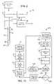
- FIG. 2schematically illustrates components that may be included in the treatment system.
- FIG. 3is a schematic cross-sectional view of an embodiment of a distal portion of the probe and system of FIG. 1B , showing a replaceable needle and an pressure relief valve with a limited exhaust volume.
- FIG. 3Aillustrates an exemplary fused silica cooling fluid supply tube for use in the replaceable needle of FIG. 3 .
- FIG. 4is a more detailed view of a replaceable needle assembly for use in the system of FIGS. 1A and 1B .
- FIGS. 5A-5Cillustrate an exemplary supply valve for use in the probe and system of FIGS. 1A and 1B .
- FIGS. 6-8illustrate skin-engaging surfaces that selectably limit an effective insertable length of the needle, that apply pain-dulling pressure, and that apply inflammation-inhibiting cooling to the skin before and/or during treatment of the target tissue, respectively.
- FIGS. 9 , 9 A, and 9 Bschematically illustrate a needle having an elongate cross-section to enhance the volume of treated tissue.
- FIG. 10schematically illustrates a thermal model of a cryogenic microprobe needle.
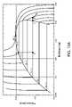
- FIGS. 10A-10Cgraphically illustrate aspects of cryogenic cooling using nitrous oxide in the microprobe needles described herein.
- FIGS. 11A and 11Bschematically illustrate cross-sectional views cooling with a one needle system and a multiple needle system.
- FIG. 12graphically illustrates non-uniform cooling that can result from inadequate evaporation space within a small cryogenic needle probe.
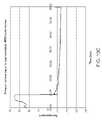
- FIGS. 13A-13Dgraphically illustrate effects of changes in exhaust volume on the cooling response by a small cryogenic needle probe.
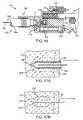
- FIG. 14schematically illustrates a cryogenic microprobe needle system being used for a dermatological treatment.
- FIG. 15is a flow chart schematically illustrating a method for treatment using the disposable cryogenic probe and system of FIG. 1B .
- FIG. 16is a schematic cross-sectional view showing an alternative exemplary needle interface, along with the adjacent structures of the needle assembly and probe body.
- FIGS. 17A and 17Bare partial cross-sectional views schematically illustrating removal of a cryogenic cooling probe needle while at least a portion of the tissue remains frozen.
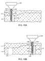
- FIGS. 18A and 18Bare partial cross-sectional views schematically illustrating how a depletion of liquid from a vaporizing cryogenic cooling fluid can be used to limit an effective treatment length on a portion of a cryogenic probe.
- Embodiments of the inventionwill facilitate remodeling of tissues disposed at and below the skin, optionally to treat a cosmetic defect, a lesion, a disease state, and/or so as to alter a shape of the overlying skin surface.
- Among the most immediate applications of the present inventionmay be the amelioration of lines and wrinkles, particularly by inhibiting muscular contractions which are associated with these cosmetic defects so as so improve an appearance of the patient.
- many embodiments of the inventionwill at least in part employ cold to immobilize muscles.
- nerves, muscles, and associated tissuesmay be temporarily immobilized using moderately cold temperatures of 10° C. to ⁇ 5° C. without permanently disabling the tissue structures.
- a needle probe or other treatment devicecan be used to identify a target tissue structure in a diagnostic mode with these moderate temperatures, and the same probe (or a different probe) can also be used to provide a longer term or permanent treatment, optionally by ablating the target tissue zone and/or inducing apoptosis at temperatures from about ⁇ 5° C. to about ⁇ 50° C.
- apoptosismay be induced using treatment temperatures from about ⁇ 1° C. to about ⁇ 15° C., or from about ⁇ 1° C.
- cryogenic coolingfor treatment of cosmetic and other defects may be found in co-pending U.S. patent application Ser. No. 11/295,204, filed on Dec. 5, 2005 and entitled “Subdermal Cryogenic Remodeling of Muscle, Nerves, Connective Tissue, and/or Adipose Tissue (Fat),” the full disclosure of which is incorporated herein by reference.
- embodiments of the inventionmay also find applications for treatments of subdermal adipose tissues, benign, pre-malignant lesions, malignant lesions, acne and a wide range of other dermatological conditions (including dermatological conditions for which cryogenic treatments have been proposed and additional dermatological conditions), and the like.
- Embodiments of the inventionmay also find applications for alleviation of pain, including those associated with muscle spasms. Hence, a variety of embodiments may be provided.
- a system for cryogenic remodelinghere comprises a self-contained probe handpiece generally having a proximal end 12 and a distal end 14 .
- a handpiece body or housing 16has a size and shape suitable for supporting in a hand of a surgeon or other system operator.
- a cryogenic cooling fluid supply 18 and electrical power source 20are found within housing 16 , along with a circuit 22 having a processor for controlling cooling applied by self-contained system 10 in response to actuation of an input 24 .
- Some embodimentsmay, at least in part, be manually activated, such as through the use of a manual supply valve and/or the like, so that processors, electrical power supplies, and the like may be absent.
- Probe 26Extending distally from distal end 14 of housing 16 is a tissue-penetrating cryogenic cooling probe 26 .
- Probe 26is thermally coupled to a cooling fluid path extending from cooling fluid source 18 , with the exemplary probe comprising a tubular body receiving at least a portion of the cooling fluid from the cooling fluid source therein.
- the exemplary probe 26comprises a 30 g needle having a sharpened distal end that is axially sealed.
- Probe 26may have an axial length between distal end 14 of housing 16 and the distal end of the needle of between about 1 ⁇ 2 mm and 5 cm, preferably having a length from about 1 cm to about 3 cm.
- needlesmay comprise a stainless steel tube with an inner diameter of about 0.006 inches and an outer diameter of about 0.012 inches, while alternative probes may comprise structures having outer diameters (or other lateral cross-sectional dimensions) from about 0.006 inches to about 0.100 inches.
- needle probe 26will comprise a 16 g or smaller size needle, often comprising a 20 g needle or smaller, typically comprising a 25 g or smaller needle.
- the exemplary cooling fluid supply 18comprises a cartridge containing a liquid under pressure, with the liquid preferably having a boiling temperature of the less than 37° C.
- the fluidis thermally coupled to the tissue-penetrating probe 26 , and the probe is positioned within the patient so that an outer surface of the probe is adjacent to a target tissue, the heat from the target tissue evaporates at least a portion of the liquid and the enthalpy of vaporization cools the target tissue.
- a valve(not shown) may be disposed along the cooling fluid flow path between cartridge 18 and probe 26 , or along the cooling fluid path after the probe so as to limit the temperature, time, rate of temperature change, or other cooling characteristics.
- the valvewill often be powered electrically via power source 20 , per the direction of processor 22 , but may at least in part be manually powered.
- the exemplary power source 20comprises a rechargeable or single-use battery.
- the exemplary cooling fluid supply 18comprises a single-use cartridge.
- the cartridge and cooling fluid thereinmay be stored and/or used at (or even above) room temperature.
- the cartridgesmay have a frangible seal or may be refillable, with the exemplary cartridge containing liquid N 2 O.
- a variety of alternative cooling fluidsmight also be used, with exemplary cooling fluids including fluorocarbon refrigerants and/or carbon dioxide.
- the quantity of cooling fluid contained by cartridge 18will typically be sufficient to treat at least a significant region of a patient, but will often be less than sufficient to treat two or more patients.
- An exemplary liquid N 2 O cartridgemight contain, for example, a quantity in a range from about 7 g to about 30 g of liquid.
- Processor 22will typically comprise a programmable electronic microprocessor embodying machine readable computer code or programming instructions for implementing one or more of the treatment methods described herein.
- the microprocessorwill typically include or be coupled to a memory (such as a non-volatile memory, a flash memory, a read-only memory (“ROM”), a random access memory (“RAM”), or the like) storing the computer code and data to be used thereby, and/or a recording media (including a magnetic recording media such as a hard disk, a floppy disk, or the like; or an optical recording media such as a CD or DVD) may be provided.
- a memorysuch as a non-volatile memory, a flash memory, a read-only memory (“ROM”), a random access memory (“RAM”), or the like
- a recording mediaincluding a magnetic recording media such as a hard disk, a floppy disk, or the like; or an optical recording media such as a CD or DVD
- Suitable interface devicessuch as digital-to-analog or analog-to-digital converters, or the like
- input/output devicessuch as USB or serial I/O ports, wireless communication cards, graphical display cards, and the like
- processor 22may be integrated on a single processor board and may run a single program or may make use of a plurality of boards running a number of different program modules in a wide variety of alternative distributed data processing or code architectures.
- Supply valvemay comprise an electrically actuated solenoid valve or the like operating in response to control signals from controller 22 , and/or may comprise a manual valve.
- Exemplary supply valvesmay comprise structures suitable for on/off valve operation, and may provide venting of the cooling fluid path downstream of the valve when cooling flow is halted so as to limit residual cryogenic fluid vaporization and cooling. More complex flow modulating valve structures might also be used in other embodiments.
- the cooling fluid from valve 32flows through a lumen 34 of a cooling fluid supply tube 36 .
- Supply tube 36is, at least in part, disposed within a lumen 38 of needle 26 , with the supply tube extending distally from a proximal end 40 of the needle toward a distal end 42 .
- the exemplary supply tube 36comprises a fused silica tubular structure 36 a having a polymer coating 36 b (see FIG. 3A ) and extends in cantilever into the needle lumen 38 .
- Supply tube 36may have an inner lumen with an effective inner diameter 36 c of less than about 200 ⁇ m, the inner diameter often being less than about 100 ⁇ m, and typically being less than about 40 ⁇ m.
- Exemplary embodiments of supply tube 36have inner lumens of between about 15 and 50 ⁇ m, such as about 30 ⁇ m.
- An outer diameter or size 36 d of supply tube 36will typically be less than about 1000 ⁇ m, often being less than about 800 ⁇ m, with exemplary embodiments being between about 60 and 150 ⁇ m, such as about 90 ⁇ m or 105 ⁇ m.
- the tolerance of the inner lumen diameter of supply tubing 36will preferably be relatively tight, typically being about ⁇ 10 ⁇ m or tighter, often being +/ ⁇ 5 ⁇ m or tighter, and ideally being +/ ⁇ 3 ⁇ m or tighter, as the small diameter supply tube may provide the majority of (or even substantially all of) the metering of the cooling fluid flow into needle 26 .
- supply tubes 36 having outer jackets of polyimide (or other suitable polymer materials)may bend within the surrounding needle lumen 38 , the supply tube should have sufficient strength to avoid collapsing or excessive blow back during injection of cooling fluid into the needle.
- Polyimide coatingsmay also provide durability during assembly and use, and the fused silica/polymer structures can handle pressures of up to 100 kpsi.
- the relatively thin tubing wall and small outer size of the preferred supply tubesallows adequate space for vaporization of the nitrous oxide or other cooling fluid within the annular space between the supply tube 36 and surrounding needle lumen 38 . Inadequate space for vaporization might otherwise cause a buildup of liquid in that annular space and inconsistent temperatures, as illustrated in FIG. 12 .
- Exemplary structures for use as supply tube 36may include the flexible fused silica capillary tubing sold commercially by Polymicro Technologies, LLC of Phoenix, Ariz. under model names TSP, TSG, and TSU, optionally including model numbers TSP 020090, TSP040105, and/or others.
- the cooling fluid injected into lumen 38 of needle 26will typically comprises liquid, though some gas may also be injected. At least some of the liquid vaporizes within needle 26 , and the enthalpy of vaporization cools the tissue engaged by the needle. Controlling a pressure of the gas/liquid mixture within needle 26 substantially controls the temperature within lumen 38 , and hence the treatment temperature range of the tissue.
- a relatively simple mechanical pressure relief valve 46may be used to control the pressure within the lumen of the needle, with the exemplary valve comprising a valve body 48 (here in the form of a ball bearing) urged against a valve seat 50 by a biasing spring 52 .
- a large volume along the cooling fluid pathway between the exit from the supply tube and exit from the pressure relief valve 46may cause excessive transients.
- a large volume in this areamay result in initial temperatures that are significantly colder than a target and/or steady state temperature, as can be seen in FIG. 13D .
- Thiscan be problematic, particularly when (for example) the target temperature is only slightly warmer than an undesirable effect inducing temperature, such as when remodeling through apoptosis or the like while seeking to inhibit necrosis.
- the pressure relief valve 46may be integrated into a housing 54 supporting needle 26 , with the valve spring 52 being located outside the valve seat (and hence the pressure-control exit from pressure relief valve 46 ).
- pressure relief valve 46is also located adjacent the interface between the needle assembly and probe handpiece housing 54 .
- a detent 56may be engaged by a spring supported catch to hold the needle assembly releasably in position, and the components of the needle assembly 26 A (such as a brass or other metallic housing, a polyimide tubing 58 , needle 26 , and the like) may be affixed together using adhesive.
- the needle assembly and handpiece housingmay have corresponding threads for mounting and replacement of the needle assembly.
- O-rings 60can seal the cooling fluid pathway.
- FIGS. 13A-13Cpresent additional details on the effects of exhaust volume on cooling transients.
- a graph of temperature over timeis shown for the outside temperature of an in vivo 30 g cooling needle with a target temperature of about ⁇ 12° C.
- the deviceswere constructed with different exhaust volumes, with the volume being greater than about 0.009 in 3 in the embodiment of FIG. 13A .
- the embodiment of FIGS. 13B and 13Chad exhaust volumes of about 0.009 in 3 and about 0.0025 in 3 , respectively.
- the data collection ratewas about 0.7 sec for the embodiment of FIG. 13A , while the embodiments of FIGS. 13B and 13C both had data collection rates of about 0.1 sec, so that the actual nadir for the embodiment of FIG. 13A may have actually been significantly lower than that shown.
- the exhaust volumeis preferably less than about 0.05 in 3 , typically being less than 0.01 in 3 and/or 0.009 in 3 , and ideally being less than 0.005 in 3 .
- the supply valvemight be cycled on and off, typically by controller 22 , with a timing sequence that would limit the cooling fluid flowing so that only vaporized gas reached the needle lumen (or a sufficiently limited amount of liquid to avoid excessive dropping of the needle lumen temperature). This cycling might be ended once the exhaust volume pressure was sufficient so that the refrigeration temperature would be within desired limits during steady state flow.
- FIGS. 2 , 3 , and 5 A- 5 CAdditional aspects of the exemplary supply valves 32 can be understood with reference to FIGS. 2 , 3 , and 5 A- 5 C.
- FIG. 3the valve is shown in the “on” configuration, with O-rings 60 sealing either side of the cooling fluid flow path and the cooling fluid flowing around the movable valve member.
- FIGS. 5A-5Cthe cooling fluid flows through a passage 64 that extends axially along an alternative valve body of valve body 32 ′ when the valve is in the on configuration (seen in FIG. 5B ), with the O-rings being disposed between recesses in the movable valve body so as to allow the valve to operate when the valve body is in any rotational orientation about its axis.
- the cooling fluid flow path downstream of the valveis vented when the valve is in the “off” configuration (in the embodiment of FIG. 3 , by channel 66 , and in the embodiment of FIGS. 5A-5C by the vaporizing cooling fluid flowing through the annular space between the valve body and the adjacent housing 54 so as to preserve the cooling fluid within the movable valve body).
- Venting of the cooling fluid from the cooling fluid supply tube 36 when the cooling fluid flow is halted by supply valve 32 , 32 ′is advantageous to provide a rapid halt to the cooling of needle 26 .
- a 2.5 cm long 30 g needle cooled to an outside temperature of ⁇ 15° C.might use only about 0.003 g/sec of nitrous oxide after the system approaches or reaches steady state (for example, 10 seconds after initiation of cooling).
- FIG. 10Analytical models that may be used to derive these cooling flows include that illustrated in FIG. 10 , which may be combined with the properties of the cooling fluid (such as the pressure/enthalpy diagram of nitrous oxide seen in FIG. 10A ) and the thermal properties of tissue shown in Table I to determine theoretical minimum cooling fluid flow rates (see FIG. 10B ), theoretical minimum cooling fluid quantities (see FIG. 10C ), and the like.
- Fluid supply 18may be initially opened for use by penetrating a frangible seal of the cartridge with a pierce point 70 (such as by tightening a threaded cartridge support coupled to housing 54 ), with the nitrous being filtered by a filter 72 before being transmitted further along the cooling fluid path.
- Suitable filtersmay have pore sizes of from about 6 to about 25 ⁇ m, and may be available commercially from Porex of Georgia (or a variety of alternative suppliers), or may comprise a fine stainless steel screen (such as those having a mesh size of 635 with 0.0009′′ wire and spacing between the wire edges of approximately 0.0006′′), or the like.
- a wide variety of epoxy or other adhesives 74may be used, and the replaceable needle housing 24 A and other structural components may comprise a wide variety of metals or polymers, including brass or the like. Fins 76 may be included to help vaporize excess cooling liquid traveling proximally of the insertable length of needle 26 .
- Very fine needleswill typically be used to deliver to cooling at and/or below the surface of the skin. These needles can be damaged relatively easily if they strike a bone, or may otherwise be damaged or deformed before or during use. Fine needles well help inhibit damage to the skin during insertion, but may not be suitable for repeated insertion for treatment of numerous treatment sites or lesions of a particular patient, or for sequential treatment of a large area of the patient. Hence, the structures shown in FIGS. 1B , 3 , and 4 allow the use probe bodies 16 , 54 with a plurality of sequentially replaceable needles.
- O-rings 60help to isolate the cooling fluid supply flow (which may be at pressures of up to about 900 psi) from the exhaust gas (which may be at a controlled pressure in a range between about 50 and 400 psi, depending on the desired temperature).
- Exemplary O-ringsmay comprise hydrogenated Buna-N O-rings, or the like.
- needle assemblies having differing numbers of needles in a needle arraymay also be selected and mounted to the probe body.
- Other embodimentsmay employ a single needle array fixedly mounted to the probe body, or a plurality of replaceable needle assemblies which all include the same number of needles.
- cooling fluid flow to a plurality of needlesmay be provided, for example, by inserting and bonding a plurality of fused silica supply tubes into a 0.010 polyimide tubing 58 or header within the needle assembly, and by advancing the distal end of each supply tube into a lumen of an associated needle 26 .
- the needlesmight vent into a common exhaust space coaxially around polyimide tubing 58 in a manner similar to the single needle design shown. This can increase the quantity of tissue treated adjacent and/or between needles, as can be seen by comparing the theoretical 15 second exposures to one and two needles having a ⁇ 15° C. probe surface, as shown in FIGS. 11A and 11B , respectively.
- a distally oriented surface 82 supported by probe body 54 adjacent and/or around the proximal end of the needlesmay be configured to limit heat transfer to or from the skin when the needle 26 is inserted so that surface 82 engages the skin and cooling fluid flows into the needle.
- Exemplary heat transfer limiting surfacesmay be formed, for example, from a small rigid foam pad or body 84 . Closed cell polyethylene foam or StyrofoamTM foam bodies may be used. As seen in FIG.
- an alternatively selectable set of bodiesmay also have differing thicknesses between the skin engaging-surface 82 and a surface 86 that engages the distal portion of the probe body.
- a usercan then select an insertable length of the needle by selecting an appropriate probe body 84 , 84 a , 84 b and mounting the selected probe body onto the needles.
- Skin engaging surface 82 of bodies 84 , 84 a , and 84 bmay be used to apply pressure to the skin, lesion, and/or target tissue during treatment.
- Alternative insertable length varying arrangementsmay also be provided, including those having threaded or other articulatable structures supporting the skin engaging surface 82 relative to the adjacent probe body 54 and the like.
- the application of pressure before, during, and/or after coolingmay help dull or otherwise inhibit sharp pain. Such pain may otherwise result from the skin penetration, cooling, or thawing of the target and/or collateral tissues. It may also be beneficial to obscure the patient's view of the cooling needles, and/or to cover the needles when not in use so as to inhibit needle-stick injuries and potential disease transmission.
- skin-engaging surface 82may be supported by an articulatable support structure having a first configuration (shown in solid in FIG. 7 ) and a second configuration (shown dashed in FIG. 7 ).
- a simple spring mechanismmay be used to apply a desired contact force between the skin-engaging surface 82 and the patient before insertion and during cooling. More sophisticated arrangements can also be employed in which the needle is driven distally and then proximally relative to the skin engaging surface appropriate times after sufficient pressure is applied to the patient, and the like.
- FIG. 8still further alternative embodiments may be provided, in this case to apply different cooling temperatures to the patient, and/or to apply cooling to the skin surface and to a target tissue adjacent needle 26 .
- different cooling temperaturessuch as to about ⁇ 10° C.
- FIG. 14cooling of a target tissue TT cylinder around needle 26 sufficient to kill bacteria in the sebaceous gland and enlarged follicle opening (such as to about ⁇ 20° C.).
- This dual temperature treatmentmay be particularly beneficial for severe forms of acne involving cysts or nodules.
- tissue engaging surface 82that surface may be thermally coupled to a chamber 88 .
- Cooling fluidmay be transmitted into chamber 88 by a port of a cooling fluid supply tube 36 , and the pressure of chamber 88 (and hence the temperature within the chamber) can optionally be controlled by a dedicated additional pressure relief valve 46 a . As the pressure within chamber 88 may differ from that within the needle, different treatment temperatures may be provided.
- the structures described hereincan also be combined, for example, with the dual skin surface/needle temperature treatment structure of FIG. 8 being compatible with the replaceable needle systems of FIGS. 1B , 3 , and/or 4 .
- the dual skin surface/needle treatment systems and methodsmay also be compatible, for example, with the articulatable skin surface supports of FIG. 7 so as to apply cooled pressure to the skin prior to and/or during needle insertion using a flexible fluid supply tube or the like.
- Still further alternativesmay also be provided, including systems that generate a high rate of cooling to promote necrosis of malignant lesions or the like.
- High cooling rateslimit osmotic effects in the target tissue.
- Slow coolingmay tend to promote ice formation between cells rather than within cells due to the osmotic effect.
- the needle probes described hereinwill often be well suited to induce rapid cooling rates of the target tissue by vaporizing the cooling fluid in close thermal and spatial proximity to that target tissue.
- cooling ratesof about 25° C./sec or more, or even about 50° C./sec or more can be provided.
- needles having circular cross-sectional shapescan often be used, but may not always provide the desired surface area for the cross-sectional area of the needle. Increased surface area may decrease the amount of time the needle is inserted to cool a volume of tissue to a temperature in a target range. Hence, a needle with an elongate outer cross-section such as elliptical needle 90 may be desirable.
- a distal cutting edge 92 at the distal tipmay facilitate insertion and a circular cross-section 94 near the proximal end may limit cooling adjacent the skin, while cooling of the target tissue therebetween is enhanced by elliptical cross-section 96 .
- Method 100facilitates treating a patient using a cryogenic cooling system having a self-contained disposable handpiece and replaceable needles such as those of FIG. 1B .
- Method 100generally begins with a determination 110 of the desired tissue remodeling and results, such as the alleviation of specific cosmetic wrinkles of the face, the inhibition of pain from a particular site, the alleviation of unsightly skin lesions or cosmetic defects from a region of the face, or the like.
- Appropriate target tissues for treatmentare identified 112 (such as the subdermal muscles that induce the wrinkles, a tissue that transmits the pain signal, or the lesion-inducing infected tissues), allowing a target treatment depth, target treatment temperature profile, or the like to be determined 114 .
- An appropriate needle assemblycan then be mounted 116 to the handpiece, with the needle assembly optionally having a needle length, skin surface cooling chamber, needle array, and/or other components suitable for treatment of the target tissues.
- Simpler systemsmay include only a single needle type, and/or a first needle assembly mounted to the handpiece.
- pressure, cooling, or bothmay be applied 118 to the skin surface adjacent the needle insertion site before, during, and/or after insertion 120 and cryogenic cooling 122 of the needle and associated target tissue.
- the needlecan then be retracted 124 from the target tissue. If the treatment is not complete 126 and the needle is not yet dull 128 , pressure and/or cooling can be applied to the next needle insertion location site 118 , and the additional target tissue treated.
- any needles that are dulled (or otherwise determined to be sufficiently used to warrant replacement, regardless of whether it is after a single insertion, 5 insertions, or the like) during the treatmentmay be replaced with a new needle 116 before the next application of pressure/cooling 118 , needle insertion 120 , and/or the like.
- the used handpiece and needlescan be disposed of 130 .
- target treatment temperatures, times, and cyclesmay be applied to differing target tissues to as to achieve the desired remodeling.
- desired temperature ranges to temporarily and/or permanently disable muscle, as well as protect the skin and surrounding tissuesmay be indicated by Table TI as follows:
- tissue treatment temperaturesmay be employed per Table III as follows:
- Treatmentlasts only while the Can be used to identify target needle is inserted into the tissues. target tissue. From 0° C. to ⁇ 5° C. Often lasts days or weeks, and Temporary treatment. Can be target tissue can repair itself. used to evaluate effectiveness Embodiments may last hours of remodeling treatment on or days. skin surface shape or the like. From ⁇ 5° C. to ⁇ 15° C. Often lasts months to years; Long term, potentially and may be permanent. permanent cosmetic benefits. Limited muscle repair. Can be deployed in limited Embodiments may last weeks doses over to time to achieve to months. staged impact, controlling outcome and avoiding negative outcome. May be employed as the standard treatment. From ⁇ 15° C.
- Embodimentsmay last years. are not desired or to evaluate outcomes of potentially permanent dosing. Embodiments may provide permanent treatment.
- Apoptosismay exhibit a non-inflammatory cell death. Without inflammation, normal muscular healing processes may be inhibited. Following many muscular injuries (including many injuries involving necrosis), skeletal muscle satellite cells may be mobilized by inflammation. Without inflammation, such mobilization may be limited or avoided. Apoptotic cell death may reduce muscle mass and/or may interrupt the collagen and elastin connective chain.
- Temperature ranges that generate a mixture of these apoptosis and necrosismay also provide long-lasting or permanent benefits.
- a permanent effectmay be advantageous.
- both apoptosis and necrosismay produce long-term or even permanent results in adipose tissues, since fat cells regenerate differently than muscle cells.
- Needle probe 162is included in a needle assembly having a needle hub 166 with a lumen containing a polyimide tube 168 around a fused silica cooling fluid supply tube with its polyimide jacket 170 .
- O-rings 172seal in exhaust gas path 174 and inlet cooling fluid path 176 , with the inlet path having a vent 178 to minimize run-on cooling when the cooling fluid supply is shut off by a valve 180 , as generally described above.
- the valveis here actuated by a motor 182 , while the exhaust gas pressure is controlled using a biasing spring and ball valve 184 as described above.
- a hollow set screw 186can be used to assemble and/or adjust the pressure relief valve, and a thermistor 188 can be used to sense cooling gas flow.
- cryogenic cooling probes 196 , 198are inserted into a target tissue TT and a flow of cryogenic cooling fluid is injected into the needle as generally described above.
- a region 200 of target tissue TTis cooled sufficiently to freeze and effect the desired remodeling of at least a portion of the target tissue.
- a lubricious coating 202facilitates removal of the needle while at least a portion of the frozen target tissue remains frozen.
- the lubricious coating 202may comprise a material having a thermal conductivity which is significantly less than that of the underlying probe structure 204 .
- Coating 202may have a thickness which is significantly less than that of the underlying probe structure 204 , limiting the total insulation effect of the coating, and/or an interior temperature of probe 196 may be reduced so as to provide the desired overall cooling treatment. While it may be counterintuitive to cool the target tissue through a thermally insulating lubricious coating, the ability to more rapidly remove probe 196 from the patient can significantly increase the speed with which procedures may be performed, particularly when a large number of insertion/cooling/removal cycles are involved, and/or when the thaw time is at least half as long as (often being as long as or longer than) the active cooling time.
- a small surface 206 of probe 196may be free of lubricious coating 202 .
- the underlying probe structure 204comprises an electrical conductor such as stainless steel or some alternative metal
- the uncovered surface portion 206may be used as an electrode for neurostimulation during positioning of probe 196 or the like.
- microneedle probe 198has a cross-sectional size of a 20-gauge needle or less, preferably comprising a 25-gauge needle or smaller, and ideally comprising a 30-gauge needle. These small diameter microneedle probes have little thermal mass and can be warmed relatively quickly by conduction from adjacent tissues and/or by any warm fluids flowing therein. As a result, while a major portion 208 of the target tissue remains frozen a layer 210 disposed between the still-frozen region and probe 198 may facilitate safe removal of the probe from the patient.
- Thawed layer 210may comprise thawed target tissue, thawed extracellular fluids, or the like. Small needles also have small probe/tissue interface surface areas which may limit the total stiction between the probe and frozen tissue. Regardless of any particular mechanism of action, the use of small diameter cryogenic microneedles may allow safe removal of the probe from a treated tissue in a time which is significantly less than that associated with complete thaw of the iceball that has been formed. Exemplary embodiments using a lubricious coating and/or small diameter probe may allow the probe to be removed within about 10 seconds of the cooling, optionally allowing safe removal within about 5 seconds of cooling or even within about 3 seconds of cooling.
- Probes 220 , 222are replaceably supported by a probe body 224 via a needle receptacle or interface, as generally described above.
- Each probeincludes a lumen 226 with a cooling fluid supply tube 228 extending to a distal port 230 .
- the supply tubecan be used to meter cooling fluid.
- cooling of the target tissue TT along a distal portion 232 of probe 228is cooled by evaporation of the liquid included in the cryogenic cooling fluid.
- cooling of a collateral tissue CT proximal of the target tissue TTmay be limited by controlling the amount of cooling fluid flow so that the vaporizing liquid is depleted by the time the flow reaches a proximal portion 234 of the probe.
- a greater length of probe 222is cooled by providing a relatively larger quantity of cooling fluid (and liquid) flowing from the supply tube 238 into lumen 226 via port 230 , so that liquid remains present for vaporization throughout a longer distal portion 232 of the probe. Note that the difference in lengths of the cooled portion 232 may be provided despite making use of an outer probe structure that is similar in cross section and/or overall length.
- proximal portion 234 of probes 220 , 222may be cooled somewhat (via conduction from the distal portion 232 of the probe, from the passage of gas vaporized from the gas of the cooling fluid, or the like), a temperature of collateral tissue CT may remain above the remodeling treatment temperature of a treatment zone 238 within the target tissue. Hence, the collateral tissue may avoid injury despite the absence of any additional insulation on the proximal portion of the probe. This also facilitates the use of differing treatment zones 238 at different locations for a particular patient through the selection of needle assemblies having appropriate cooling fluid supply paths with the desired differing cooling fluid flow characteristics.
- one or more temperature feedback loopsmay be used to control the treatments, with the tissue temperature optionally being taken using a temperature sensing needle having a temperature sensor disposed adjacent an outer cooled skin engaging surface of the needle.
- the scope of the present inventionis limited solely by the independent claims.
Landscapes
- Health & Medical Sciences (AREA)
- Surgery (AREA)
- Life Sciences & Earth Sciences (AREA)
- Nuclear Medicine, Radiotherapy & Molecular Imaging (AREA)
- Medical Informatics (AREA)
- Engineering & Computer Science (AREA)
- Biomedical Technology (AREA)
- Heart & Thoracic Surgery (AREA)
- Otolaryngology (AREA)
- Molecular Biology (AREA)
- Animal Behavior & Ethology (AREA)
- General Health & Medical Sciences (AREA)
- Public Health (AREA)
- Veterinary Medicine (AREA)
- Surgical Instruments (AREA)
- Thermotherapy And Cooling Therapy Devices (AREA)
Abstract
Description
0.1 cc*(0.7 g/cc)=0.07 g of liquid nitrous oxide,
0.07 g/(0.003 g/sec)=23 sec.
These calculation assume a fused silica supply tube sized to allow the minimum flow of nitrous oxide when fluid supply has a pressure of about 900 psi. When the supply valve is shut off, the pressure on the needle side of the supply valve would decay, causing the actual residual run time to be longer, with only a partial cooling near the distal tip of
| TABLE I | ||
| Property | Units | Value |
| Upper temperature bond of freezing (T2) | ° C. | −1 |
| Peak of phase transition temperature (T3) | ° C. | −3 |
| Lower Temperature bond of freezing (T1) | ° C. | −8 |
| Thermal conductivity in unfrozen region (ku) | W/(mm-° C.) | 0.00063 |
| Thermal conductivity in frozen region (kf) | W/(mm-° C.) | 0.00151 |
| Volumetric specific heat in unfrozen | J/(mm3-° C. | 0.00316 |
| region ({ρtct}f) | ||
| Volumetric specific heat in frozen | J/mm3-° C. | 0.00193 |
| region ({ρtct}f) | ||
| Latent heat of solidification (HF) | J/mm3 | 0.300 |
| TABLE II | |||
| Temperature | Skin | Muscle/ | |
| 37° | baseline | baseline | |
| 25° | cold sensation | ||
| 18° C. | reflex vasodilation of | ||
| 15° C. | |||
| 12° C. | reduction of | ||
| 10° C. | very cold sensation | ||
| reduction of chronic | |||
| Hunting response | |||
| 5° | pain sensation | ||
| 0° C. | freezing point | ||
| −1° C. | Phase transition begins | ||
| −2° C. | minimal apoptosis | ||
| −3° C. | Peak phase transition | ||
| −5° C. | tissue damage | moderate apoptosis | |
| −8° C. | Completion of phase transition | ||
| −10° C. | considerable apoptosis | ||
| −15° C. | extensive apoptosis | ||
| mild-moderate necrosis | |||
| −19° C. | adoptosis in some skeletal | ||
| muscle tissues | |||
| −40° C. | extensive necrosis | ||
| TABLE III | ||
| Cooled | ||
| Temperature Range | Time Effectiveness | Purpose |
| ≧0° C. | Treatment lasts only while the | Can be used to identify target |
| needle is inserted into the | tissues. | |
| target tissue. | ||
| From 0° C. to −5° C. | Often lasts days or weeks, and | Temporary treatment. Can be |
| target tissue can repair itself. | used to evaluate effectiveness | |
| Embodiments may last hours | of remodeling treatment on | |
| or days. | skin surface shape or the like. | |
| From −5° C. to −15° C. | Often lasts months to years; | Long term, potentially |
| and may be permanent. | permanent cosmetic benefits. | |
| Limited muscle repair. | Can be deployed in limited | |
| Embodiments may last weeks | doses over to time to achieve | |
| to months. | staged impact, controlling | |
| outcome and avoiding negative | ||
| outcome. May be employed as | ||
| the standard treatment. | ||
| From −15° C. to −25° C. | Often lasts weeks or months. | May result in Mid-term |
| Muscle may repair itself via | cosmetic benefits, and can be | |
| satellite cell mobilization. | used where permanent effects | |
| Embodiments may last years. | are not desired or to evaluate | |
| outcomes of potentially | ||
| permanent dosing. | ||
| Embodiments may provide | ||
| permanent treatment. | ||
Claims (14)
Priority Applications (10)
| Application Number | Priority Date | Filing Date | Title |
|---|---|---|---|
| US11/675,886US8409185B2 (en) | 2007-02-16 | 2007-02-16 | Replaceable and/or easily removable needle systems for dermal and transdermal cryogenic remodeling |
| JP2009549704AJP5427611B2 (en) | 2007-02-16 | 2008-02-13 | Interchangeable and / or easily removable needle system for cutaneous and percutaneous cryogenic remodeling |
| PCT/US2008/053876WO2008101027A2 (en) | 2007-02-16 | 2008-02-13 | Replaceable and/or easily removable needle systems for dermal and transdermal cryogenic remodeling |
| ES08729785.9TES2439492T3 (en) | 2007-02-16 | 2008-02-13 | Replaceable and / or easy-to-remove needle systems for dermal and transdermal cryogenic remodeling |
| PL08729785TPL2111172T3 (en) | 2007-02-16 | 2008-02-13 | Replaceable and/or easily removable needle systems for dermal and transdermal cryogenic remodeling |
| EP08729785.9AEP2111172B1 (en) | 2007-02-16 | 2008-02-13 | Replaceable and/or easily removable needle systems for dermal and transdermal cryogenic remodeling |
| EP13179642.7AEP2676623B1 (en) | 2007-02-16 | 2008-02-13 | Replaceable and/or easily removable needle systems for dermal and transdermal cryogenic remodeling |
| CA002677811ACA2677811A1 (en) | 2007-02-16 | 2008-02-13 | Replaceable and/or easily removable needle systems for dermal and transdermal cryogenic remodeling |
| US13/786,407US9113855B2 (en) | 2007-02-16 | 2013-03-05 | Replaceable and/or easily removable needle systems for dermal and transdermal cryogenic remodeling |
| JP2013249148AJP2014138726A (en) | 2007-02-16 | 2013-12-02 | Replaceable and/or easily removable needle systems for dermal and transdermal cryogenic remodeling |
Applications Claiming Priority (1)
| Application Number | Priority Date | Filing Date | Title |
|---|---|---|---|
| US11/675,886US8409185B2 (en) | 2007-02-16 | 2007-02-16 | Replaceable and/or easily removable needle systems for dermal and transdermal cryogenic remodeling |
Related Child Applications (1)
| Application Number | Title | Priority Date | Filing Date |
|---|---|---|---|
| US13/786,407ContinuationUS9113855B2 (en) | 2007-02-16 | 2013-03-05 | Replaceable and/or easily removable needle systems for dermal and transdermal cryogenic remodeling |
Publications (2)
| Publication Number | Publication Date |
|---|---|
| US20080200910A1 US20080200910A1 (en) | 2008-08-21 |
| US8409185B2true US8409185B2 (en) | 2013-04-02 |
Family
ID=39690778
Family Applications (2)
| Application Number | Title | Priority Date | Filing Date |
|---|---|---|---|
| US11/675,886Active2032-01-30US8409185B2 (en) | 2007-02-16 | 2007-02-16 | Replaceable and/or easily removable needle systems for dermal and transdermal cryogenic remodeling |
| US13/786,407Active2027-04-28US9113855B2 (en) | 2007-02-16 | 2013-03-05 | Replaceable and/or easily removable needle systems for dermal and transdermal cryogenic remodeling |
Family Applications After (1)
| Application Number | Title | Priority Date | Filing Date |
|---|---|---|---|
| US13/786,407Active2027-04-28US9113855B2 (en) | 2007-02-16 | 2013-03-05 | Replaceable and/or easily removable needle systems for dermal and transdermal cryogenic remodeling |
Country Status (7)
| Country | Link |
|---|---|
| US (2) | US8409185B2 (en) |
| EP (2) | EP2676623B1 (en) |
| JP (2) | JP5427611B2 (en) |
| CA (1) | CA2677811A1 (en) |
| ES (1) | ES2439492T3 (en) |
| PL (1) | PL2111172T3 (en) |
| WO (1) | WO2008101027A2 (en) |
Cited By (37)
| Publication number | Priority date | Publication date | Assignee | Title |
|---|---|---|---|---|
| US9017318B2 (en) | 2012-01-20 | 2015-04-28 | Myoscience, Inc. | Cryogenic probe system and method |
| US9066712B2 (en) | 2008-12-22 | 2015-06-30 | Myoscience, Inc. | Integrated cryosurgical system with refrigerant and electrical power source |
| US9072498B2 (en) | 2005-05-20 | 2015-07-07 | Myoscience, Inc. | Subdermal cryogenic remodeling of muscles, nerves, connective tissue, and/or adipose tissue (fat) |
| US9101346B2 (en) | 2007-11-14 | 2015-08-11 | Myoscience, Inc. | Pain management using cryogenic remodeling |
| US9113855B2 (en) | 2007-02-16 | 2015-08-25 | Myoscience, Inc. | Replaceable and/or easily removable needle systems for dermal and transdermal cryogenic remodeling |
| US9155584B2 (en) | 2012-01-13 | 2015-10-13 | Myoscience, Inc. | Cryogenic probe filtration system |
| US9241753B2 (en) | 2012-01-13 | 2016-01-26 | Myoscience, Inc. | Skin protection for subdermal cryogenic remodeling for cosmetic and other treatments |
| US9295512B2 (en) | 2013-03-15 | 2016-03-29 | Myoscience, Inc. | Methods and devices for pain management |
| US9314290B2 (en) | 2012-01-13 | 2016-04-19 | Myoscience, Inc. | Cryogenic needle with freeze zone regulation |
| US9345526B2 (en) | 2005-05-20 | 2016-05-24 | Myoscience, Inc. | Subdermal cryogenic remodeling of muscles, nerves, connective tissue, and/or adipose tissue (fat) |
| US9610112B2 (en) | 2013-03-15 | 2017-04-04 | Myoscience, Inc. | Cryogenic enhancement of joint function, alleviation of joint stiffness and/or alleviation of pain associated with osteoarthritis |
| US9668800B2 (en) | 2013-03-15 | 2017-06-06 | Myoscience, Inc. | Methods and systems for treatment of spasticity |
| US10130409B2 (en) | 2013-11-05 | 2018-11-20 | Myoscience, Inc. | Secure cryosurgical treatment system |
| US10226585B2 (en) | 2014-10-01 | 2019-03-12 | Allergan, Inc. | Devices for injection and dosing |
| US10265477B2 (en) | 2013-05-23 | 2019-04-23 | Allergan, Inc. | Mechanical syringe accessory |
| US10433928B2 (en) | 2015-03-10 | 2019-10-08 | Allergan Pharmaceuticals Holdings (Ireland) Unlimited Company | Multiple needle injector |
| USD865949S1 (en) | 2017-03-24 | 2019-11-05 | Allergan, Inc. | Syringe device |
| US10470813B2 (en) | 2015-03-12 | 2019-11-12 | Pacira Cryotech, Inc. | Methods and systems for preventing neuroma formations |
| US10596321B2 (en) | 2016-04-08 | 2020-03-24 | Allergan, Inc. | Aspiration and injection device |
| US10792427B2 (en) | 2014-05-13 | 2020-10-06 | Allergan, Inc. | High force injection devices |
| US10888366B2 (en) | 2013-03-15 | 2021-01-12 | Pacira Cryotech, Inc. | Cryogenic blunt dissection methods and devices |
| US10939947B2 (en) | 2006-12-21 | 2021-03-09 | Pacira Cryotech, Inc. | Dermal and transdermal cryogenic microprobe systems |
| US10980596B2 (en) | 2006-02-07 | 2021-04-20 | Viveve, Inc. | Vaginal remodeling device and methods |
| US11020098B2 (en)* | 2014-09-09 | 2021-06-01 | Boston Scientific Scimed, Inc. | Methods, systems and devices for cryogenic biopsy |
| US11134998B2 (en) | 2017-11-15 | 2021-10-05 | Pacira Cryotech, Inc. | Integrated cold therapy and electrical stimulation systems for locating and treating nerves and associated methods |
| US11154349B2 (en) | 2009-09-18 | 2021-10-26 | Viveve, Inc. | Vaginal remodeling device and methods |
| US11154874B2 (en)* | 2018-12-17 | 2021-10-26 | Cryoconcepts Lp | Flow modulation device for dispensing pressurized fluids |
| US11311327B2 (en) | 2016-05-13 | 2022-04-26 | Pacira Cryotech, Inc. | Methods and systems for locating and treating nerves with cold therapy |
| US11511110B2 (en) | 2018-06-27 | 2022-11-29 | Viveve, Inc. | Methods for treating urinary stress incontinence |
| US11523855B2 (en) | 2018-09-28 | 2022-12-13 | Team Neuro LLC | Spinal pain management system and method |
| US11684719B2 (en) | 2013-05-23 | 2023-06-27 | Allergan, Inc. | Methods of treatment using a syringe extrusion accessory |
| US11740759B2 (en) | 2019-11-27 | 2023-08-29 | Pacira Cryotech, Inc. | Display device and interfaces for cryogenic devices |
| US11779383B2 (en) | 2019-12-03 | 2023-10-10 | Pacira Cryotech, Inc. | Stabilizing pressure in cryogenic devices |
| US11957397B2 (en) | 2019-10-29 | 2024-04-16 | Pacira Cryotech, Inc. | Cryogenic device with quick-connect needle probes |
| US11992668B2 (en) | 2008-12-02 | 2024-05-28 | Allergan, Inc. | Injection device |
| US12369965B2 (en) | 2021-12-30 | 2025-07-29 | Cryosa, Inc. | Systems and methods for treatment of obstructive sleep apnea |
| US12419780B2 (en) | 2018-04-27 | 2025-09-23 | Recensmedical, Inc. | Hand-held cryotherapy device including cryogen temperature pressure controller and method thereof |
Families Citing this family (45)
| Publication number | Priority date | Publication date | Assignee | Title |
|---|---|---|---|---|
| EP2301471A1 (en) | 2004-04-01 | 2011-03-30 | The General Hospital Corporation | Method and apparatus for dermatological treatment and tissue reshaping |
| US8571648B2 (en)* | 2004-05-07 | 2013-10-29 | Aesthera | Apparatus and method to apply substances to tissue |
| US7842029B2 (en)* | 2004-05-07 | 2010-11-30 | Aesthera | Apparatus and method having a cooling material and reduced pressure to treat biological external tissue |
| US20060047281A1 (en) | 2004-09-01 | 2006-03-02 | Syneron Medical Ltd. | Method and system for invasive skin treatment |
| US20090005786A1 (en)* | 2007-06-28 | 2009-01-01 | Stryker Trauma Gmbh | Bone hole measuring device |
| US20090012434A1 (en)* | 2007-07-03 | 2009-01-08 | Anderson Robert S | Apparatus, method, and system to treat a volume of skin |
| US20090069795A1 (en)* | 2007-09-10 | 2009-03-12 | Anderson Robert S | Apparatus and method for selective treatment of tissue |
| US20090093864A1 (en)* | 2007-10-08 | 2009-04-09 | Anderson Robert S | Methods and devices for applying energy to tissue |
| MX2010007860A (en) | 2008-01-17 | 2010-11-30 | Syneron Medical Ltd | A hair removal apparatus for personal use and the method of using same. |
| EP2237732A4 (en) | 2008-01-24 | 2011-06-01 | Syneron Medical Ltd | A device, apparatus, and method of adipose tissue treatment |
| US20120022512A1 (en)* | 2008-01-24 | 2012-01-26 | Boris Vaynberg | Device, apparatus, and method of adipose tissue treatment |
| US20120022504A1 (en)* | 2008-09-11 | 2012-01-26 | Syneron Medical Ltd. | Device, apparatus, and method of adipose tissue treatment |
| EP2334249B1 (en) | 2008-09-21 | 2013-03-13 | Syneron Medical Ltd. | A method and apparatus for personal skin treatment |
| EP2730313A1 (en) | 2009-02-25 | 2014-05-14 | Syneron Medical Ltd. | Electrical skin rejuvenation |
| US8888768B2 (en)* | 2009-04-30 | 2014-11-18 | Cryomedix, Llc | Cryoablation system having docking station for charging cryogen containers and related method |
| RU2463990C2 (en)* | 2010-10-18 | 2012-10-20 | Михаил Иванович Ярославцев | Method of moisturising, rejuvenation and cleansing of skin and device for its realisation |
| CN103561673A (en) | 2010-12-13 | 2014-02-05 | 肌肉科技股份有限公司 | Method for reducing hyperdynamic facial wrinkles |
| US9078634B2 (en) | 2011-01-27 | 2015-07-14 | Cryosa, Llc | Apparatus and methods for treatment of obstructive sleep apnea utilizing cryolysis of adipose tissues |
| US9011350B2 (en) | 2011-11-30 | 2015-04-21 | Lincoln Diagnostics, Inc. | Allergy testing device and method of testing for allergies |
| WO2013106857A1 (en) | 2012-01-13 | 2013-07-18 | Myoscience, Inc. | Skin protection for subdermal cryogenic remodeling for cosmetic and other treatments |
| US9078733B2 (en)* | 2012-08-08 | 2015-07-14 | Galil Medical Inc. | Closed-loop system for cryosurgery |
| EP3200736B8 (en) | 2014-10-01 | 2020-06-17 | CryOSA, Inc. | Apparatus for treatment of obstructive sleep apnea utilizing cryolysis of adipose tissues |
| JP2016154807A (en)* | 2015-02-26 | 2016-09-01 | 国立大学法人東北大学 | Auxiliary instrument for clinical application |
| KR101905830B1 (en) | 2016-11-15 | 2018-10-08 | 울산과학기술원 | Cryoanesthesia device, method for controlling cryoanesthesia device and temperature controller of coolant in cryoanesthesia device |
| US11324673B2 (en)* | 2016-11-18 | 2022-05-10 | Miraki Innovation Think Tank Llc | Cosmetic appearance of skin |
| KR20180131357A (en) | 2017-05-30 | 2018-12-10 | 주식회사 리센스메디컬 | Medical cooling apparatus |
| WO2018221848A1 (en) | 2017-05-30 | 2018-12-06 | 주식회사 리센스메디컬 | Medical cooling device |
| KR102517065B1 (en) | 2017-12-29 | 2023-04-03 | 주식회사 리센스메디컬 | Cooling generator |
| US11179185B2 (en)* | 2018-07-20 | 2021-11-23 | Atricure, Inc. | Cryogenic surgical systems |
| CN112955099B (en) | 2018-07-27 | 2024-04-26 | 雷森斯医疗有限公司 | Medical cooling device and cooling method using same |
| US11666479B2 (en) | 2018-08-19 | 2023-06-06 | Recensmedical, Inc. | Device for cooling anesthesia by chilled fluidic cooling medium |
| US10610280B1 (en) | 2019-02-02 | 2020-04-07 | Ayad K. M. Agha | Surgical method and apparatus for destruction and removal of intraperitoneal, visceral, and subcutaneous fat |
| USD921211S1 (en) | 2019-06-21 | 2021-06-01 | Recensmedical, Inc. | Medical cooling device |
| USD921911S1 (en) | 2019-06-21 | 2021-06-08 | Recensmedical, Inc. | Medical cooling device |
| US12121281B2 (en) | 2019-08-07 | 2024-10-22 | Christopher M. Shaari | Systems and methods for cryogenic treatment of headache |
| EP4069113A4 (en)* | 2019-12-02 | 2024-03-20 | Pacira CryoTech, Inc. | CRYOGENIC DEVICES WITH VENTING FEATURES |
| CN111603634B (en)* | 2020-06-04 | 2021-06-15 | 江苏省人民医院(南京医科大学第一附属医院) | Automatic selection platform and method for injection needle |
| US11278341B2 (en) | 2020-07-14 | 2022-03-22 | Recensmedical, Inc. | Method of safely using controlled cooling systems and devices |
| EP4183378B1 (en)* | 2020-07-14 | 2025-08-27 | Recensmedical, Inc. | Medical cooling system and medical cooling device using same |
| USD968626S1 (en) | 2020-08-07 | 2022-11-01 | Recensmedical, Inc. | Medical cooling device |
| USD977633S1 (en) | 2020-08-07 | 2023-02-07 | Recensmedical, Inc. | Cradle for a medical cooling device |
| USD968627S1 (en) | 2020-08-07 | 2022-11-01 | Recensmedical, Inc. | Medical cooling device |
| US12364531B2 (en) | 2021-02-16 | 2025-07-22 | RecensMedical, Inc.; | Methods for treating skin disorders using precision cooling technology |
| CN113457026A (en)* | 2021-07-30 | 2021-10-01 | 南方医科大学南方医院 | Medical foaming adhesive perfusion apparatus for manufacturing radiotherapy foaming adhesive shaping pad |
| CN114469331B (en)* | 2022-01-24 | 2024-05-14 | 南京佰福激光技术有限公司 | Liquid nitrogen equipment is spouted in dispersion of laser therapeutic instrument |
Citations (133)
| Publication number | Priority date | Publication date | Assignee | Title |
|---|---|---|---|---|
| US2319542A (en) | 1940-06-24 | 1943-05-18 | Franklin E Hall | Therapeutic machine |
| US2672032A (en) | 1951-10-19 | 1954-03-16 | Towse Robert Albert Edward | Carcass freezing device |
| US3226492A (en) | 1961-06-30 | 1965-12-28 | Ericsson Telefon Ab L M | Circuit arrangement for telephone instruments |
| US3343544A (en) | 1965-12-21 | 1967-09-26 | Alcon Lab Inc | Cryogenic surgical instrument |
| US3507283A (en) | 1967-10-11 | 1970-04-21 | Univ Northwestern | Cryosurgical instrument |
| US3532094A (en) | 1967-07-20 | 1970-10-06 | Norman O Stahl | Cryogenic-instrument with detachable probe |
| US3664344A (en) | 1970-09-15 | 1972-05-23 | Brymill Corp | Tyned cryosurgical probe |
| US3795245A (en) | 1971-04-29 | 1974-03-05 | Al Co Du | Splash-proof leak-proof syringe-type cryosurgical instrument |
| GB1360353A (en) | 1972-01-19 | 1974-07-17 | Atomic Energy Authority Uk | Method of making thermocouples |
| US3830239A (en) | 1972-09-12 | 1974-08-20 | Frigitronics Of Conn Inc | Cryosurgical device |
| US3886945A (en) | 1972-06-14 | 1975-06-03 | Frigitronics Of Conn Inc | Cryosurgical apparatus |
| US3889681A (en) | 1974-10-30 | 1975-06-17 | Jack Douglas Waller | Cryosurgical spraying apparatus |
| GB1402632A (en) | 1972-02-02 | 1975-08-13 | Wilkinson Sword Ltd | Medical equipment |
| US3951152A (en) | 1974-06-03 | 1976-04-20 | Dynatech Corporation | Cryosurgical probe |
| US3993075A (en) | 1975-12-24 | 1976-11-23 | Dynatech Corporation | Disposable, defrostable cryosurgical probe |
| US4140109A (en) | 1977-10-17 | 1979-02-20 | Savic Michael I | Impedance-based method and apparatus for monitoring cryodestruction in controlled cryosurgery |
| US4207897A (en) | 1976-07-21 | 1980-06-17 | Spembly Limited | Cryosurgical probe |
| US4306568A (en) | 1979-12-04 | 1981-12-22 | Torre Douglas P | Method and apparatus for congelation cryometry in cryosurgery |
| EP0043447A2 (en) | 1980-06-13 | 1982-01-13 | Karl-Heinz Kreibel | Low-temperature transmission device for medical purposes |
| US4376376A (en) | 1980-05-12 | 1983-03-15 | Virginia M. Gregory | Cryogenic device operable in single or dual phase with a range of nozzle sizes and method of using the same |
| US4404862A (en) | 1981-11-02 | 1983-09-20 | Dynatech Precision Sampling Corporation | Microdispensing springs with a needle in a tubular extension |
| US4524771A (en) | 1982-10-28 | 1985-06-25 | Ethicon Inc. | Multiple curved surgical needle |
| US4758217A (en) | 1986-05-05 | 1988-07-19 | L'oreal | Method for obtaining a cryogenic treatment effect for the cutaneous covering and a unit for the implementation of this method |
| US4802475A (en) | 1987-06-22 | 1989-02-07 | Weshahy Ahmed H A G | Methods and apparatus of applying intra-lesional cryotherapy |
| US4946460A (en) | 1989-04-26 | 1990-08-07 | Cryo Instruments, Inc. | Apparatus for cryosurgery |
| US5200170A (en) | 1989-07-18 | 1993-04-06 | Mcdow Ronald A | Medical process--use of dichlorodifluoromethane (CCl2 F2) and chlorodifluoromethane (CHClF2) as cryogens for treating skin lesions |
| US5334181A (en) | 1990-09-26 | 1994-08-02 | Cryomedical Sciences, Inc. | Cryosurgical system for destroying tumors by freezing |
| US5571147A (en) | 1993-11-02 | 1996-11-05 | Sluijter; Menno E. | Thermal denervation of an intervertebral disc for relief of back pain |
| EP0777123A2 (en) | 1994-03-09 | 1997-06-04 | Thomas P. Castellano | Medication delivery device with a microprocessor and characteristic monitor |
| US5647868A (en) | 1994-02-02 | 1997-07-15 | Chinn; Douglas Owen | Cryosurgical integrated control and monitoring system and method |
| US5755753A (en) | 1995-05-05 | 1998-05-26 | Thermage, Inc. | Method for controlled contraction of collagen tissue |
| US5814040A (en) | 1994-04-05 | 1998-09-29 | The Regents Of The University Of California | Apparatus and method for dynamic cooling of biological tissues for thermal mediated surgery |
| US5899897A (en) | 1996-09-26 | 1999-05-04 | Allegheny-Singer Research Institute | Method and apparatus for heating during cryosurgery |
| US5916212A (en) | 1998-01-23 | 1999-06-29 | Cryomedical Sciences, Inc. | Hand held cyrosurgical probe system |
| US5976505A (en) | 1997-07-02 | 1999-11-02 | Hcs Trust | Method for cryogenically treating psoriasis with liquid nitrogen or liquid nitrous oxide |
| US6003539A (en) | 1998-01-20 | 1999-12-21 | Nok Corporation | Differential pressure regulating valve and liquid shut-off valve device |
| US6032675A (en) | 1997-03-17 | 2000-03-07 | Rubinsky; Boris | Freezing method for controlled removal of fatty tissue by liposuction |
| US6039730A (en) | 1996-06-24 | 2000-03-21 | Allegheny-Singer Research Institute | Method and apparatus for cryosurgery |
| US6041787A (en) | 1997-03-17 | 2000-03-28 | Rubinsky; Boris | Use of cryoprotective agent compounds during cryosurgery |
| US6139545A (en) | 1998-09-09 | 2000-10-31 | Vidaderm | Systems and methods for ablating discrete motor nerve regions |
| US6141985A (en) | 1998-03-06 | 2000-11-07 | Societe Cryonic Medical | Self-contained and portable cryogenic apparatus using carbon dioxide in liquid/solid phases |
| US6182666B1 (en) | 1996-12-26 | 2001-02-06 | Cryogen, Inc. | Cryosurgical probe and method for uterine ablation |
| EP1074273A1 (en) | 1999-08-06 | 2001-02-07 | Becton Dickinson and Company | Improved medication delivery pen |
| US6196839B1 (en) | 1999-01-29 | 2001-03-06 | Robert Gregg Ross | Continuous use orthodontic cooling appliance |
| US6277116B1 (en) | 1994-05-06 | 2001-08-21 | Vidaderm | Systems and methods for shrinking collagen in the dermis |
| US20020013602A1 (en) | 2000-07-31 | 2002-01-31 | Huttner James J. | Method for controlling the pain from injections or minor surgical procedures and apparatus for use therewith |
| US20020068929A1 (en) | 2000-10-24 | 2002-06-06 | Roni Zvuloni | Apparatus and method for compressing a gas, and cryosurgery system and method utilizing same |
| US6432102B2 (en) | 1999-03-15 | 2002-08-13 | Cryovascular Systems, Inc. | Cryosurgical fluid supply |
| US6494844B1 (en) | 2000-06-21 | 2002-12-17 | Sanarus Medical, Inc. | Device for biopsy and treatment of breast tumors |
| US20020193778A1 (en) | 1999-10-14 | 2002-12-19 | Alchas Paul G. | Method of intradermally injecting substances |
| US6503246B1 (en) | 2000-07-05 | 2003-01-07 | Mor Research Applications Ltd. | Cryoprobe and method of treating scars |
| US6506796B1 (en) | 1995-10-09 | 2003-01-14 | Centre International De Recherches Dermatologiques Galderma | Use of a RAR-γ-specific agonist ligand for increasing the rate of apoptosis |
| US20030036752A1 (en) | 2001-08-13 | 2003-02-20 | Cryovascular Systems, Inc. | Cryotherapy methods for treating vessel dissections and side branch occlusion |
| US6546935B2 (en) | 2000-04-27 | 2003-04-15 | Atricure, Inc. | Method for transmural ablation |
| US6551309B1 (en) | 2000-09-14 | 2003-04-22 | Cryoflex, Inc. | Dual action cryoprobe and methods of using the same |
| US6562030B1 (en) | 1999-04-06 | 2003-05-13 | Cryocath Technologies Inc. | Heater control of cryocatheter tip temperature |
| US20030109912A1 (en) | 1999-02-24 | 2003-06-12 | Cryovascular Systems, Inc. | Cryogenically enhanced intravascular interventions |
| US20030181896A1 (en) | 2001-09-27 | 2003-09-25 | Roni Zvuloni | Apparatus and method for cryosurgical treatment of tumors of the breast |
| US6648880B2 (en) | 2001-02-16 | 2003-11-18 | Cryocath Technologies Inc. | Method of using cryotreatment to treat brain tissue |
| US6669688B2 (en) | 2000-01-25 | 2003-12-30 | The Regents Of The University Of California | Method and apparatus for measuring the heat transfer coefficient during cryogen spray cooling of tissue |
| US6672095B1 (en) | 2002-06-28 | 2004-01-06 | Chin-Kuang Luo | Therapeutic freezing device and method |
| US6706037B2 (en) | 2000-10-24 | 2004-03-16 | Galil Medical Ltd. | Multiple cryoprobe apparatus and method |
| US6723092B2 (en) | 2000-12-15 | 2004-04-20 | Tony R. Brown | Atrial fibrillation RF treatment device and method |
| WO2004039440A1 (en) | 2002-10-30 | 2004-05-13 | Tecpharma Licensing Ag | Method and device for display and dosing on administration of a product |
| US6749624B2 (en) | 1996-01-05 | 2004-06-15 | Edward W. Knowlton | Fluid delivery apparatus |
| US20040122482A1 (en) | 2002-12-20 | 2004-06-24 | James Tung | Nerve proximity method and device |
| US6761715B2 (en) | 2001-04-26 | 2004-07-13 | Ronald J. Carroll | Method and device for neurocryo analgesia and anesthesia |
| US6764493B1 (en) | 1999-01-20 | 2004-07-20 | Pearl Technology Holdings, Llc | Tissue removal using biocompatible materials |
| US20040162551A1 (en) | 2000-12-15 | 2004-08-19 | Brown Tony R. | Method and device for creating transmural lesions |
| US6789545B2 (en) | 2002-10-04 | 2004-09-14 | Sanarus Medical, Inc. | Method and system for cryoablating fibroadenomas |
| US20040191229A1 (en) | 2002-10-09 | 2004-09-30 | Link Charles J. | Antitumor vaccination using allogeneic tumor cells expressing alpha (1,3)-galactosyltransferase |
| US20040204705A1 (en) | 2003-04-10 | 2004-10-14 | Scimed Life Systems, Inc. | Cryotreatment devices and methods of forming conduction blocks |
| US20040210212A1 (en) | 2002-08-06 | 2004-10-21 | Maurice George T | Cryo-surgical apparatus and method of use |
| US20040215294A1 (en) | 2003-01-15 | 2004-10-28 | Mediphysics Llp | Cryotherapy probe |
| US20040225276A1 (en)* | 2003-03-13 | 2004-11-11 | Burgess Cheryl M. | Methods of administering a material into a patient for dermal enhancement |
| US6840935B2 (en)* | 2000-08-09 | 2005-01-11 | Bekl Corporation | Gynecological ablation procedure and system using an ablation needle |
| US6905492B2 (en) | 2000-07-31 | 2005-06-14 | Galil Medical Ltd. | Planning and facilitation systems and methods for cryosurgery |
| RU2254060C2 (en) | 1999-10-27 | 2005-06-20 | Энсон Медикал Лимитед | Method for manufacturing medical implants and device for suturing tubular medical implant walls |
| US20050177148A1 (en) | 2003-12-22 | 2005-08-11 | Van Der Walt Nicholas R. | Cryosurgical devices for endometrial ablation |
| WO2005079321A2 (en) | 2004-02-12 | 2005-09-01 | Sanarus Medical, Inc. | Rotational core biopsy device with liquid cryogen adhesion probe |
| US20050203593A1 (en) | 2003-10-24 | 2005-09-15 | Shanks Steven C. | Method for dermatology therapies in combination with low level laser treatments |
| US20050203505A1 (en) | 2004-03-15 | 2005-09-15 | Scimed Life Systems, Inc. | Ablation probe with peltier effect thermal control |
| US20050209565A1 (en) | 1999-06-09 | 2005-09-22 | The Procter & Gamble Company | Intracutaneous microneedle array apparatus |
| US20050209587A1 (en) | 1997-12-02 | 2005-09-22 | Cryovascular Systems,Inc. | Apparatus and method for cryogenic inhibition of hyperplasia |
| US20050228288A1 (en)* | 2003-01-16 | 2005-10-13 | Charlotte-Mecklenburg Hospital Authority D/B/A Carolinas Medical Center | Echogenic needle for transvaginal ultrasound directed reduction of uterine fibroids and an associated method |
| US6960208B2 (en) | 2003-06-30 | 2005-11-01 | Boston Scientific Scimed, Inc. | Apparatus and methods for delivering energy to a target site within bone |
| US20050261753A1 (en) | 2003-01-15 | 2005-11-24 | Mediphysics Llp | Methods and systems for cryogenic cooling |
| US20050276759A1 (en) | 1994-12-02 | 2005-12-15 | Roser Bruce J | Solid dose delivery vehicle and methods of making same |
| US20050283148A1 (en) | 2004-06-17 | 2005-12-22 | Janssen William M | Ablation apparatus and system to limit nerve conduction |
| US20060015092A1 (en) | 2000-08-18 | 2006-01-19 | Cryovascular Systems, Inc. | Cryotherapy method for detecting and treating vulnerable plaque |
| US7001400B1 (en) | 1999-03-04 | 2006-02-21 | Abbott Laboratories | Articulating suturing device and method |
| US20060069385A1 (en) | 2004-09-28 | 2006-03-30 | Scimed Life Systems, Inc. | Methods and apparatus for tissue cryotherapy |
| US20060079914A1 (en) | 1999-03-04 | 2006-04-13 | Modesitt D B | Articulating suturing device and method |
| US20060084962A1 (en) | 2004-06-02 | 2006-04-20 | Cryovascular Systems, Inc. | Controllable pressure cryogenic balloon treatment system and method |
| JP2006130055A (en) | 2004-11-05 | 2006-05-25 | Tohoku Univ | Cryotherapy apparatus using Peltier module / element and cryotherapy temperature control method using Peltier module / element |
| US20060111732A1 (en) | 2002-10-03 | 2006-05-25 | George Gibbens | Cycling suturing and knot-tying device |
| US20060129142A1 (en) | 2004-12-15 | 2006-06-15 | Cryovascular Systems, Inc. | Efficient controlled cryogenic fluid delivery into a balloon catheter and other treatment devices |
| US20060142785A1 (en) | 1999-03-04 | 2006-06-29 | Modesitt D B | Articulating suturing device and method |
| US7081111B2 (en) | 2001-05-16 | 2006-07-25 | Optomed. As | Cryosurgical apparatus and methods |
| US7083612B2 (en) | 2003-01-15 | 2006-08-01 | Cryodynamics, Llc | Cryotherapy system |
| US20060173469A1 (en) | 2001-01-24 | 2006-08-03 | Klein Enrique J | Device and method for suturing of internal puncture sites |
| US20060189968A1 (en) | 2003-08-19 | 2006-08-24 | Howlett Harold A | Cryosurgery device |
| US20060190035A1 (en) | 2004-10-08 | 2006-08-24 | Sherwood Services Ag | Latching mechanism for forceps |
| US20060200117A1 (en) | 2002-11-18 | 2006-09-07 | Erik Hermans | Instrument for cryogenic treatments in the medical, paramedical and cosmetic field |
| US20060212048A1 (en) | 2005-03-21 | 2006-09-21 | Design Standards Corporation | Suturing device |
| US20060223052A1 (en) | 2005-03-30 | 2006-10-05 | Kimberly-Clark Worldwide, Inc. | Technique for detecting microorganisms |
| US7195616B2 (en) | 2001-05-16 | 2007-03-27 | Eli Lilly And Company | Medication injector apparatus with drive assembly that facilitates reset |
| US20070088217A1 (en) | 2005-10-13 | 2007-04-19 | Babaev Eilaz P | Apparatus and methods for the selective removal of tissue using combinations of ultrasonic energy and cryogenic energy |
| US20070129714A1 (en) | 2005-05-20 | 2007-06-07 | Echo Healthcare Llc | Subdermal cryogenic remodeling of muscles, nerves, connective tissue, and/or adipose tissue (FAT) |
| US20070156125A1 (en) | 2005-12-30 | 2007-07-05 | Russell Delonzor | Encodable cryogenic device |
| US20070161975A1 (en) | 2006-01-06 | 2007-07-12 | Olga Goulko | Cryogenic applicator for rejuvenating human skin and related method |
| US20070167959A1 (en) | 1999-03-04 | 2007-07-19 | Abbott Laboratories | Articulating suturing device and method |
| US20070179509A1 (en) | 2005-12-26 | 2007-08-02 | Nippon Sherwood Medical Industries Ltd. | Medical Suturing Device |
| US20070198071A1 (en) | 2006-02-22 | 2007-08-23 | Juniper Medical Systems | Cooling device for removing heat from subcutaneous lipid-rich cells |
| EP1377327B1 (en) | 2001-04-13 | 2007-09-19 | Becton, Dickinson and Company | Prefillable intradermal delivery device |
| US20070255362A1 (en) | 2006-04-28 | 2007-11-01 | Juniper Medical, Inc. | Cryoprotectant for use with a cooling device for improved cooling of subcutaneous lipid-rich cells |
| US20070270925A1 (en) | 2006-05-17 | 2007-11-22 | Juniper Medical, Inc. | Method and apparatus for non-invasively removing heat from subcutaneous lipid-rich cells including a coolant having a phase transition temperature |
| US7311672B2 (en) | 2000-10-16 | 2007-12-25 | Sanarus Medical, Inc. | Device for biopsy of tumors |
| US20080077202A1 (en) | 2006-09-26 | 2008-03-27 | Juniper Medical, Inc. | Tissue Treatment Methods |
| US20080077201A1 (en) | 2006-09-26 | 2008-03-27 | Juniper Medical, Inc. | Cooling devices with flexible sensors |
| US20080077211A1 (en) | 2006-09-26 | 2008-03-27 | Juniper Medical, Inc. | Cooling device having a plurality of controllable cooling elements to provide a predetermined cooling profile |
| US7367341B2 (en) | 2002-03-15 | 2008-05-06 | The General Hospital Corporation | Methods and devices for selective disruption of fatty tissue by controlled cooling |
| US20080154254A1 (en) | 2006-12-21 | 2008-06-26 | Myoscience, Inc. | Dermal and Transdermal Cryogenic Microprobe Systems and Methods |
| US20080183164A1 (en) | 2005-05-20 | 2008-07-31 | Myoscience, Inc. | Subdermal cryogenic remodeling of muscles, nerves, connective tissue, and/or adipose tissue (fat) |
| US7422586B2 (en) | 2001-02-28 | 2008-09-09 | Angiodynamics, Inc. | Tissue surface treatment apparatus and method |
| US20080287839A1 (en) | 2007-05-18 | 2008-11-20 | Juniper Medical, Inc. | Method of enhanced removal of heat from subcutaneous lipid-rich cells and treatment apparatus having an actuator |
| US20090018627A1 (en) | 2007-07-13 | 2009-01-15 | Juniper Medical, Inc. | Secure systems for removing heat from lipid-rich regions |
| US20090018623A1 (en) | 2007-07-13 | 2009-01-15 | Juniper Medical, Inc. | System for treating lipid-rich regions |
| US20090018625A1 (en) | 2007-07-13 | 2009-01-15 | Juniper Medical, Inc. | Managing system temperature to remove heat from lipid-rich regions |
| US20090018624A1 (en) | 2007-07-13 | 2009-01-15 | Juniper Medical, Inc. | Limiting use of disposable system patient protection devices |
| US20090018626A1 (en) | 2007-07-13 | 2009-01-15 | Juniper Medical, Inc. | User interfaces for a system that removes heat from lipid-rich regions |
| US20090248001A1 (en) | 2007-11-14 | 2009-10-01 | Myoscience, Inc. | Pain management using cryogenic remodeling |
| EP1862125B1 (en) | 2006-05-31 | 2011-08-03 | Covidien AG | Medical suturing tool with gripping device |
Family Cites Families (66)
| Publication number | Priority date | Publication date | Assignee | Title |
|---|---|---|---|---|
| US3289424A (en) | 1963-07-01 | 1966-12-06 | Union Carbide Corp | Cryosurgical fluid control system |
| US3266492A (en) | 1963-09-06 | 1966-08-16 | Samuel B Steinberg | Cryosurgery probe device |
| US3351063A (en) | 1964-12-08 | 1967-11-07 | Stephen F Malaker | Cryosurgical probe |
| US3439680A (en) | 1965-04-12 | 1969-04-22 | Univ Northwestern | Surgical instrument for cataract removal |
| GB1103079A (en) | 1966-02-17 | 1968-02-14 | Internat Res And Dev Company L | Improvements in and relating to surgical probes |
| US3702114A (en) | 1970-08-26 | 1972-11-07 | Frigitronics Of Conn Inc | Liquid refrigerant spray device |
| US3814095A (en) | 1972-03-24 | 1974-06-04 | H Lubens | Occlusively applied anesthetic patch |
| US4236518A (en) | 1978-04-14 | 1980-12-02 | Gyne-Tech Instrument Corporation | Cryogenic device selectively operable in a continuous freezing mode, a continuous thawing mode or a combination thereof |
| JPS6013111B2 (en) | 1980-10-08 | 1985-04-05 | 神戸建設株式会社 | Equipment for repairing floating walls of concrete, etc. |
| JPH0538347Y2 (en) | 1987-10-28 | 1993-09-28 | ||
| GB2230191B (en) | 1989-04-15 | 1992-04-22 | Robert Graham Urie | Lesion location device |
| JP3142008B2 (en)* | 1991-06-03 | 2001-03-07 | 株式会社前川製作所 | Biological cryotherapy needle |
| JPH0538347A (en)* | 1991-08-06 | 1993-02-19 | Mayekawa Mfg Co Ltd | Freezing device for organism tissue |
| US7549424B2 (en) | 1991-10-18 | 2009-06-23 | Pro Surg, Inc. | Method and apparatus for tissue treatment with laser and electromagnetic radiation |
| EP0680283B1 (en) | 1992-04-24 | 1998-05-13 | Surgical Laser Technologies | Thermally-resistant medical probe |
| US5294325A (en) | 1992-07-09 | 1994-03-15 | World Precision Instruments, Inc. | Miniaturized fluid conveying device and methods of use thereof |
| DE4322955B4 (en) | 1992-07-20 | 2007-12-20 | Aesculap Ag & Co. Kg | Invasive surgical instrument |
| GB2289510A (en) | 1994-05-10 | 1995-11-22 | Spembly Medical Ltd | Connector |
| GB2289414B (en) | 1994-05-10 | 1998-05-13 | Spembly Medical Ltd | Cryosurgical instrument |
| JPH08206147A (en) | 1995-02-06 | 1996-08-13 | Akio Usui | Exothermic body and plaster using the same |
| JP3283716B2 (en) | 1995-04-07 | 2002-05-20 | シャープ株式会社 | Heater control device |
| US7620290B2 (en) | 1995-08-31 | 2009-11-17 | Biolase Technology, Inc. | Modified-output fiber optic tips |
| US20040000316A1 (en) | 1996-01-05 | 2004-01-01 | Knowlton Edward W. | Methods for creating tissue effect utilizing electromagnetic energy and a reverse thermal gradient |
| US7189230B2 (en) | 1996-01-05 | 2007-03-13 | Thermage, Inc. | Method for treating skin and underlying tissue |
| US6682501B1 (en) | 1996-02-23 | 2004-01-27 | Gyrus Ent, L.L.C. | Submucosal tonsillectomy apparatus and method |
| JPH1014656A (en) | 1996-07-01 | 1998-01-20 | Shigemi Kobayashi | Facial wrinkle-removing utencil |
| US7347840B2 (en) | 2000-03-02 | 2008-03-25 | Pyng Medical Corp. | Patch for locating a target zone for penetration |
| US6371943B1 (en) | 1997-09-08 | 2002-04-16 | Epimed International, Inc. | Spring tip needle combination |
| US6905494B2 (en) | 1998-03-31 | 2005-06-14 | Innercool Therapies, Inc. | Method and device for performing cooling- or cryo-therapies for, e.g., angioplasty with reduced restenosis or pulmonary vein cell necrosis to inhibit atrial fibrillation employing tissue protection |
| US6142991A (en) | 1998-03-31 | 2000-11-07 | Galil Medical, Ltd. | High resolution cryosurgical method and apparatus |
| EP1400204A1 (en) | 1999-08-05 | 2004-03-24 | Broncus Technologies, Inc. | Methods and devices for creating collateral channels in the lungs |
| JP2001178737A (en)* | 1999-12-07 | 2001-07-03 | Dieter Steinfatt | Freezer device |
| US6363730B1 (en) | 2000-03-15 | 2002-04-02 | The Conair Group, Inc. | Method and apparatus for cryogenic cooling |
| US20020045434A1 (en) | 2000-08-31 | 2002-04-18 | Lee Masoian | System and method for transmitting information modulated radio frequency signals using infrared transmission |
| US20080051776A1 (en) | 2001-05-21 | 2008-02-28 | Galil Medical Ltd. | Thin uninsulated cryoprobe and insulating probe introducer |
| US7479139B2 (en) | 2002-01-04 | 2009-01-20 | Galil Medical Ltd. | Apparatus and method for protecting tissues during cryoablation |
| US7250046B1 (en) | 2002-02-27 | 2007-07-31 | Fallat Lawrence M | Treatment of lower extremity pain |
| SE523503C2 (en) | 2002-07-23 | 2004-04-27 | Jettec Ab | Capillary |
| US6896666B2 (en) | 2002-11-08 | 2005-05-24 | Kochamba Family Trust | Cutaneous injection delivery under suction |
| CA2522939A1 (en) | 2003-04-21 | 2004-11-04 | Galil Medical Ltd. | Apparatus and method positioning a therapeutic probe with respect to a therapeutic target |
| US7207985B2 (en) | 2003-06-25 | 2007-04-24 | Endocare, Inc. | Detachable cryosurgical probe |
| US7160291B2 (en) | 2003-06-25 | 2007-01-09 | Endocare, Inc. | Detachable cryosurgical probe |
| US20050004563A1 (en) | 2003-07-01 | 2005-01-06 | Racz N. Sandor | Apparatus and methods for sensing and cooling during application of thermal energy for treating degenerative spinal discs |
| JP2005080988A (en)* | 2003-09-10 | 2005-03-31 | Ruo Mei Ryan | Crymotherapy apparatus and heat conducting needle means |
| WO2005047192A1 (en)* | 2003-11-11 | 2005-05-26 | Keith Froggatt | Water distribution system |
| US7322973B2 (en) | 2004-03-31 | 2008-01-29 | Cryocath Technologies Inc. | Method and apparatus for preventing atrial fibrillation |
| EP2301471A1 (en) | 2004-04-01 | 2011-03-30 | The General Hospital Corporation | Method and apparatus for dermatological treatment and tissue reshaping |
| KR20070039065A (en) | 2004-06-24 | 2007-04-11 | 필립 엘. 길덴버그 | Anti-robot sealing device |
| DE602005010442D1 (en) | 2004-08-16 | 2008-11-27 | Zimmer Spine Inc | SPIRAL SEWING DEVICE |
| JP5243034B2 (en)* | 2004-10-15 | 2013-07-24 | バクサノ,インク. | Tissue removal device |
| US7578819B2 (en) | 2005-05-16 | 2009-08-25 | Baxano, Inc. | Spinal access and neural localization |
| US20060089688A1 (en) | 2004-10-25 | 2006-04-27 | Dorin Panescu | Method and apparatus to reduce wrinkles through application of radio frequency energy to nerves |
| US7297136B2 (en) | 2004-12-06 | 2007-11-20 | Wyrick Ronald E | Medicine injection devices and methods |
| US20080200932A1 (en) | 2005-05-27 | 2008-08-21 | Ignacio Diaz De Tuesta Revilla | Surgical Needle Holder for Stitch Suturing |
| US20070055173A1 (en) | 2005-08-23 | 2007-03-08 | Sanarus Medical, Inc. | Rotational core biopsy device with liquid cryogen adhesion probe |
| US7875041B2 (en) | 2005-09-28 | 2011-01-25 | Olympus Medical Systems Corp. | Suturing method for penetrating hole |
| US20080051775A1 (en) | 2005-11-23 | 2008-02-28 | Evans David K | Multi-modal analgesia delivery system ("MADS") |
| CA2854625C (en) | 2006-01-27 | 2017-01-24 | Suturtek Incorporated | Apparatus and method for tissue closure |
| JP2009534156A (en) | 2006-04-24 | 2009-09-24 | トーマス・ジェファーソン・ユニバーシティ | Cryoneedle and cryotherapy system |
| WO2007129121A1 (en) | 2006-05-08 | 2007-11-15 | Tayside Health Board | Device and method for improved surgical suturing |
| WO2007135629A1 (en) | 2006-05-16 | 2007-11-29 | Orhan Seyfi Aksakal | A needle pusher |
| CA2659261C (en) | 2006-07-28 | 2017-03-07 | Centre Hospitalier Universitaire De Quebec | Probe, sleeve, system, method and kit for performing percutaneous thermotherapy |
| WO2008055243A2 (en) | 2006-10-31 | 2008-05-08 | Zeltiq Aesthetics, Inc. | Method and apparatus for cooling subcutaneous lipid-rich cells or tissue |
| US8409185B2 (en) | 2007-02-16 | 2013-04-02 | Myoscience, Inc. | Replaceable and/or easily removable needle systems for dermal and transdermal cryogenic remodeling |
| WO2009026471A1 (en) | 2007-08-21 | 2009-02-26 | Zeltiq Aesthetics, Inc. | Monitoring the cooling of subcutaneous lipid-rich cells, such as the cooling of adipose tissue |
| US20120089211A1 (en) | 2010-04-08 | 2012-04-12 | Myoscience, Inc. | Methods and apparatus for cryogenically treating multiple tissue sites with a single puncture |
- 2007
- 2007-02-16USUS11/675,886patent/US8409185B2/enactiveActive
- 2008
- 2008-02-13EPEP13179642.7Apatent/EP2676623B1/enactiveActive
- 2008-02-13ESES08729785.9Tpatent/ES2439492T3/enactiveActive
- 2008-02-13EPEP08729785.9Apatent/EP2111172B1/enactiveActive
- 2008-02-13PLPL08729785Tpatent/PL2111172T3/enunknown
- 2008-02-13WOPCT/US2008/053876patent/WO2008101027A2/enactiveApplication Filing
- 2008-02-13CACA002677811Apatent/CA2677811A1/ennot_activeAbandoned
- 2008-02-13JPJP2009549704Apatent/JP5427611B2/enactiveActive
- 2013
- 2013-03-05USUS13/786,407patent/US9113855B2/enactiveActive
- 2013-12-02JPJP2013249148Apatent/JP2014138726A/enactivePending
Patent Citations (149)
| Publication number | Priority date | Publication date | Assignee | Title |
|---|---|---|---|---|
| US2319542A (en) | 1940-06-24 | 1943-05-18 | Franklin E Hall | Therapeutic machine |
| US2672032A (en) | 1951-10-19 | 1954-03-16 | Towse Robert Albert Edward | Carcass freezing device |
| US3226492A (en) | 1961-06-30 | 1965-12-28 | Ericsson Telefon Ab L M | Circuit arrangement for telephone instruments |
| US3343544A (en) | 1965-12-21 | 1967-09-26 | Alcon Lab Inc | Cryogenic surgical instrument |
| US3532094A (en) | 1967-07-20 | 1970-10-06 | Norman O Stahl | Cryogenic-instrument with detachable probe |
| US3507283A (en) | 1967-10-11 | 1970-04-21 | Univ Northwestern | Cryosurgical instrument |
| US3664344A (en) | 1970-09-15 | 1972-05-23 | Brymill Corp | Tyned cryosurgical probe |
| US3795245A (en) | 1971-04-29 | 1974-03-05 | Al Co Du | Splash-proof leak-proof syringe-type cryosurgical instrument |
| GB1360353A (en) | 1972-01-19 | 1974-07-17 | Atomic Energy Authority Uk | Method of making thermocouples |
| GB1402632A (en) | 1972-02-02 | 1975-08-13 | Wilkinson Sword Ltd | Medical equipment |
| US3886945A (en) | 1972-06-14 | 1975-06-03 | Frigitronics Of Conn Inc | Cryosurgical apparatus |
| US3830239A (en) | 1972-09-12 | 1974-08-20 | Frigitronics Of Conn Inc | Cryosurgical device |
| US3951152A (en) | 1974-06-03 | 1976-04-20 | Dynatech Corporation | Cryosurgical probe |
| US3889681A (en) | 1974-10-30 | 1975-06-17 | Jack Douglas Waller | Cryosurgical spraying apparatus |
| US3993075A (en) | 1975-12-24 | 1976-11-23 | Dynatech Corporation | Disposable, defrostable cryosurgical probe |
| US4207897A (en) | 1976-07-21 | 1980-06-17 | Spembly Limited | Cryosurgical probe |
| US4140109A (en) | 1977-10-17 | 1979-02-20 | Savic Michael I | Impedance-based method and apparatus for monitoring cryodestruction in controlled cryosurgery |
| US4306568A (en) | 1979-12-04 | 1981-12-22 | Torre Douglas P | Method and apparatus for congelation cryometry in cryosurgery |
| US4376376A (en) | 1980-05-12 | 1983-03-15 | Virginia M. Gregory | Cryogenic device operable in single or dual phase with a range of nozzle sizes and method of using the same |
| EP0043447A2 (en) | 1980-06-13 | 1982-01-13 | Karl-Heinz Kreibel | Low-temperature transmission device for medical purposes |
| US4404862A (en) | 1981-11-02 | 1983-09-20 | Dynatech Precision Sampling Corporation | Microdispensing springs with a needle in a tubular extension |
| US4524771A (en) | 1982-10-28 | 1985-06-25 | Ethicon Inc. | Multiple curved surgical needle |
| US4758217A (en) | 1986-05-05 | 1988-07-19 | L'oreal | Method for obtaining a cryogenic treatment effect for the cutaneous covering and a unit for the implementation of this method |
| US4802475A (en) | 1987-06-22 | 1989-02-07 | Weshahy Ahmed H A G | Methods and apparatus of applying intra-lesional cryotherapy |
| US4946460A (en) | 1989-04-26 | 1990-08-07 | Cryo Instruments, Inc. | Apparatus for cryosurgery |
| US5200170A (en) | 1989-07-18 | 1993-04-06 | Mcdow Ronald A | Medical process--use of dichlorodifluoromethane (CCl2 F2) and chlorodifluoromethane (CHClF2) as cryogens for treating skin lesions |
| US5334181A (en) | 1990-09-26 | 1994-08-02 | Cryomedical Sciences, Inc. | Cryosurgical system for destroying tumors by freezing |
| US5571147A (en) | 1993-11-02 | 1996-11-05 | Sluijter; Menno E. | Thermal denervation of an intervertebral disc for relief of back pain |
| US5647868A (en) | 1994-02-02 | 1997-07-15 | Chinn; Douglas Owen | Cryosurgical integrated control and monitoring system and method |
| EP0777123A2 (en) | 1994-03-09 | 1997-06-04 | Thomas P. Castellano | Medication delivery device with a microprocessor and characteristic monitor |
| US5814040A (en) | 1994-04-05 | 1998-09-29 | The Regents Of The University Of California | Apparatus and method for dynamic cooling of biological tissues for thermal mediated surgery |
| US6277116B1 (en) | 1994-05-06 | 2001-08-21 | Vidaderm | Systems and methods for shrinking collagen in the dermis |
| US20050276759A1 (en) | 1994-12-02 | 2005-12-15 | Roser Bruce J | Solid dose delivery vehicle and methods of making same |
| US5755753A (en) | 1995-05-05 | 1998-05-26 | Thermage, Inc. | Method for controlled contraction of collagen tissue |
| US6506796B1 (en) | 1995-10-09 | 2003-01-14 | Centre International De Recherches Dermatologiques Galderma | Use of a RAR-γ-specific agonist ligand for increasing the rate of apoptosis |
| US6749624B2 (en) | 1996-01-05 | 2004-06-15 | Edward W. Knowlton | Fluid delivery apparatus |
| US6039730A (en) | 1996-06-24 | 2000-03-21 | Allegheny-Singer Research Institute | Method and apparatus for cryosurgery |
| US6786902B1 (en) | 1996-06-24 | 2004-09-07 | Allegheny-Singer Research Institute | Method and apparatus for cryosurgery |
| US5899897A (en) | 1996-09-26 | 1999-05-04 | Allegheny-Singer Research Institute | Method and apparatus for heating during cryosurgery |
| US6182666B1 (en) | 1996-12-26 | 2001-02-06 | Cryogen, Inc. | Cryosurgical probe and method for uterine ablation |
| US6032675A (en) | 1997-03-17 | 2000-03-07 | Rubinsky; Boris | Freezing method for controlled removal of fatty tissue by liposuction |
| US6041787A (en) | 1997-03-17 | 2000-03-28 | Rubinsky; Boris | Use of cryoprotective agent compounds during cryosurgery |
| US5976505A (en) | 1997-07-02 | 1999-11-02 | Hcs Trust | Method for cryogenically treating psoriasis with liquid nitrogen or liquid nitrous oxide |
| US20050209587A1 (en) | 1997-12-02 | 2005-09-22 | Cryovascular Systems,Inc. | Apparatus and method for cryogenic inhibition of hyperplasia |
| US6003539A (en) | 1998-01-20 | 1999-12-21 | Nok Corporation | Differential pressure regulating valve and liquid shut-off valve device |
| US5916212A (en) | 1998-01-23 | 1999-06-29 | Cryomedical Sciences, Inc. | Hand held cyrosurgical probe system |
| US6141985A (en) | 1998-03-06 | 2000-11-07 | Societe Cryonic Medical | Self-contained and portable cryogenic apparatus using carbon dioxide in liquid/solid phases |
| US6139545A (en) | 1998-09-09 | 2000-10-31 | Vidaderm | Systems and methods for ablating discrete motor nerve regions |
| US6764493B1 (en) | 1999-01-20 | 2004-07-20 | Pearl Technology Holdings, Llc | Tissue removal using biocompatible materials |
| US6196839B1 (en) | 1999-01-29 | 2001-03-06 | Robert Gregg Ross | Continuous use orthodontic cooling appliance |
| US20030109912A1 (en) | 1999-02-24 | 2003-06-12 | Cryovascular Systems, Inc. | Cryogenically enhanced intravascular interventions |
| US7001400B1 (en) | 1999-03-04 | 2006-02-21 | Abbott Laboratories | Articulating suturing device and method |
| US20060079914A1 (en) | 1999-03-04 | 2006-04-13 | Modesitt D B | Articulating suturing device and method |
| US20060142785A1 (en) | 1999-03-04 | 2006-06-29 | Modesitt D B | Articulating suturing device and method |
| US20070167959A1 (en) | 1999-03-04 | 2007-07-19 | Abbott Laboratories | Articulating suturing device and method |
| US20020183731A1 (en) | 1999-03-15 | 2002-12-05 | Cryovascular Systems, Inc., A Delaware Corporation | Safety cryotherapy catheter |
| US20060212028A1 (en) | 1999-03-15 | 2006-09-21 | Cryovascular Systems, Inc. | Cryosurgical fluid supply |
| US20040167505A1 (en) | 1999-03-15 | 2004-08-26 | Cryovascular Systems, Inc. | Cryosurgical fluid supply |
| US6432102B2 (en) | 1999-03-15 | 2002-08-13 | Cryovascular Systems, Inc. | Cryosurgical fluid supply |
| US6562030B1 (en) | 1999-04-06 | 2003-05-13 | Cryocath Technologies Inc. | Heater control of cryocatheter tip temperature |
| US20050209565A1 (en) | 1999-06-09 | 2005-09-22 | The Procter & Gamble Company | Intracutaneous microneedle array apparatus |
| US6277099B1 (en) | 1999-08-06 | 2001-08-21 | Becton, Dickinson And Company | Medication delivery pen |
| EP1074273A1 (en) | 1999-08-06 | 2001-02-07 | Becton Dickinson and Company | Improved medication delivery pen |
| US20020193778A1 (en) | 1999-10-14 | 2002-12-19 | Alchas Paul G. | Method of intradermally injecting substances |
| RU2254060C2 (en) | 1999-10-27 | 2005-06-20 | Энсон Медикал Лимитед | Method for manufacturing medical implants and device for suturing tubular medical implant walls |
| US6669688B2 (en) | 2000-01-25 | 2003-12-30 | The Regents Of The University Of California | Method and apparatus for measuring the heat transfer coefficient during cryogen spray cooling of tissue |
| US6546935B2 (en) | 2000-04-27 | 2003-04-15 | Atricure, Inc. | Method for transmural ablation |
| US20060009712A1 (en) | 2000-06-21 | 2006-01-12 | Sanarus, Inc. | Dual lumen device for biopsy and treatment of breast tumors and method for use |
| US6494844B1 (en) | 2000-06-21 | 2002-12-17 | Sanarus Medical, Inc. | Device for biopsy and treatment of breast tumors |
| US6503246B1 (en) | 2000-07-05 | 2003-01-07 | Mor Research Applications Ltd. | Cryoprobe and method of treating scars |
| US6905492B2 (en) | 2000-07-31 | 2005-06-14 | Galil Medical Ltd. | Planning and facilitation systems and methods for cryosurgery |
| US20020013602A1 (en) | 2000-07-31 | 2002-01-31 | Huttner James J. | Method for controlling the pain from injections or minor surgical procedures and apparatus for use therewith |
| US6840935B2 (en)* | 2000-08-09 | 2005-01-11 | Bekl Corporation | Gynecological ablation procedure and system using an ablation needle |
| US20060015092A1 (en) | 2000-08-18 | 2006-01-19 | Cryovascular Systems, Inc. | Cryotherapy method for detecting and treating vulnerable plaque |
| US6551309B1 (en) | 2000-09-14 | 2003-04-22 | Cryoflex, Inc. | Dual action cryoprobe and methods of using the same |
| US7311672B2 (en) | 2000-10-16 | 2007-12-25 | Sanarus Medical, Inc. | Device for biopsy of tumors |
| US6706037B2 (en) | 2000-10-24 | 2004-03-16 | Galil Medical Ltd. | Multiple cryoprobe apparatus and method |
| US20020068929A1 (en) | 2000-10-24 | 2002-06-06 | Roni Zvuloni | Apparatus and method for compressing a gas, and cryosurgery system and method utilizing same |
| US20040162551A1 (en) | 2000-12-15 | 2004-08-19 | Brown Tony R. | Method and device for creating transmural lesions |
| US6723092B2 (en) | 2000-12-15 | 2004-04-20 | Tony R. Brown | Atrial fibrillation RF treatment device and method |
| US20060173469A1 (en) | 2001-01-24 | 2006-08-03 | Klein Enrique J | Device and method for suturing of internal puncture sites |
| US6648880B2 (en) | 2001-02-16 | 2003-11-18 | Cryocath Technologies Inc. | Method of using cryotreatment to treat brain tissue |
| US7422586B2 (en) | 2001-02-28 | 2008-09-09 | Angiodynamics, Inc. | Tissue surface treatment apparatus and method |
| EP1377327B1 (en) | 2001-04-13 | 2007-09-19 | Becton, Dickinson and Company | Prefillable intradermal delivery device |
| US6761715B2 (en) | 2001-04-26 | 2004-07-13 | Ronald J. Carroll | Method and device for neurocryo analgesia and anesthesia |
| US7081111B2 (en) | 2001-05-16 | 2006-07-25 | Optomed. As | Cryosurgical apparatus and methods |
| US7195616B2 (en) | 2001-05-16 | 2007-03-27 | Eli Lilly And Company | Medication injector apparatus with drive assembly that facilitates reset |
| US20030036752A1 (en) | 2001-08-13 | 2003-02-20 | Cryovascular Systems, Inc. | Cryotherapy methods for treating vessel dissections and side branch occlusion |
| US20040243116A1 (en) | 2001-08-13 | 2004-12-02 | Cryovascular Systems, Inc., A Delaware Corporation | Cryotherapy methods for treating vessel dissections and side branch occlusion |
| US20030181896A1 (en) | 2001-09-27 | 2003-09-25 | Roni Zvuloni | Apparatus and method for cryosurgical treatment of tumors of the breast |
| US7367341B2 (en) | 2002-03-15 | 2008-05-06 | The General Hospital Corporation | Methods and devices for selective disruption of fatty tissue by controlled cooling |
| US6672095B1 (en) | 2002-06-28 | 2004-01-06 | Chin-Kuang Luo | Therapeutic freezing device and method |
| US6858025B2 (en) | 2002-08-06 | 2005-02-22 | Medically Advanced Designs, Llc | Cryo-surgical apparatus and method of use |
| US20040215178A1 (en) | 2002-08-06 | 2004-10-28 | Maurice George T | Cryo-surgical apparatus and method of use |
| US20040210212A1 (en) | 2002-08-06 | 2004-10-21 | Maurice George T | Cryo-surgical apparatus and method of use |
| US20060111732A1 (en) | 2002-10-03 | 2006-05-25 | George Gibbens | Cycling suturing and knot-tying device |
| US6789545B2 (en) | 2002-10-04 | 2004-09-14 | Sanarus Medical, Inc. | Method and system for cryoablating fibroadenomas |
| US20040191229A1 (en) | 2002-10-09 | 2004-09-30 | Link Charles J. | Antitumor vaccination using allogeneic tumor cells expressing alpha (1,3)-galactosyltransferase |
| US20050251103A1 (en) | 2002-10-30 | 2005-11-10 | Beat Steffen | Method and device for displaying and metering doses as a product is administered |
| WO2004039440A1 (en) | 2002-10-30 | 2004-05-13 | Tecpharma Licensing Ag | Method and device for display and dosing on administration of a product |
| US20060200117A1 (en) | 2002-11-18 | 2006-09-07 | Erik Hermans | Instrument for cryogenic treatments in the medical, paramedical and cosmetic field |
| US20040122482A1 (en) | 2002-12-20 | 2004-06-24 | James Tung | Nerve proximity method and device |
| US20050261753A1 (en) | 2003-01-15 | 2005-11-24 | Mediphysics Llp | Methods and systems for cryogenic cooling |
| US20040215294A1 (en) | 2003-01-15 | 2004-10-28 | Mediphysics Llp | Cryotherapy probe |
| US7083612B2 (en) | 2003-01-15 | 2006-08-01 | Cryodynamics, Llc | Cryotherapy system |
| US20050228288A1 (en)* | 2003-01-16 | 2005-10-13 | Charlotte-Mecklenburg Hospital Authority D/B/A Carolinas Medical Center | Echogenic needle for transvaginal ultrasound directed reduction of uterine fibroids and an associated method |
| US20040225276A1 (en)* | 2003-03-13 | 2004-11-11 | Burgess Cheryl M. | Methods of administering a material into a patient for dermal enhancement |
| US20040204705A1 (en) | 2003-04-10 | 2004-10-14 | Scimed Life Systems, Inc. | Cryotreatment devices and methods of forming conduction blocks |
| US6960208B2 (en) | 2003-06-30 | 2005-11-01 | Boston Scientific Scimed, Inc. | Apparatus and methods for delivering energy to a target site within bone |
| US20060189968A1 (en) | 2003-08-19 | 2006-08-24 | Howlett Harold A | Cryosurgery device |
| US20050203593A1 (en) | 2003-10-24 | 2005-09-15 | Shanks Steven C. | Method for dermatology therapies in combination with low level laser treatments |
| US20050177148A1 (en) | 2003-12-22 | 2005-08-11 | Van Der Walt Nicholas R. | Cryosurgical devices for endometrial ablation |
| US20050177147A1 (en) | 2003-12-22 | 2005-08-11 | Vancelette David W. | Cryosurgical devices and methods for endometrial ablation |
| WO2005079321A2 (en) | 2004-02-12 | 2005-09-01 | Sanarus Medical, Inc. | Rotational core biopsy device with liquid cryogen adhesion probe |
| US7402140B2 (en) | 2004-02-12 | 2008-07-22 | Sanarus Medical, Inc. | Rotational core biopsy device with liquid cryogen adhesion probe |
| US20050203505A1 (en) | 2004-03-15 | 2005-09-15 | Scimed Life Systems, Inc. | Ablation probe with peltier effect thermal control |
| US20060084962A1 (en) | 2004-06-02 | 2006-04-20 | Cryovascular Systems, Inc. | Controllable pressure cryogenic balloon treatment system and method |
| US20070060921A1 (en) | 2004-06-17 | 2007-03-15 | Jnj Technology Holdings Llc | Ablation apparatus and system to limit nerve conduction |
| US20050283148A1 (en) | 2004-06-17 | 2005-12-22 | Janssen William M | Ablation apparatus and system to limit nerve conduction |
| US20070167943A1 (en) | 2004-06-17 | 2007-07-19 | Jnj Technology Holdings Llc | Ablation apparatus and system to limit nerve conduction |
| US20060069385A1 (en) | 2004-09-28 | 2006-03-30 | Scimed Life Systems, Inc. | Methods and apparatus for tissue cryotherapy |
| US20060190035A1 (en) | 2004-10-08 | 2006-08-24 | Sherwood Services Ag | Latching mechanism for forceps |
| JP2006130055A (en) | 2004-11-05 | 2006-05-25 | Tohoku Univ | Cryotherapy apparatus using Peltier module / element and cryotherapy temperature control method using Peltier module / element |
| US20060129142A1 (en) | 2004-12-15 | 2006-06-15 | Cryovascular Systems, Inc. | Efficient controlled cryogenic fluid delivery into a balloon catheter and other treatment devices |
| US20060212048A1 (en) | 2005-03-21 | 2006-09-21 | Design Standards Corporation | Suturing device |
| US20060223052A1 (en) | 2005-03-30 | 2006-10-05 | Kimberly-Clark Worldwide, Inc. | Technique for detecting microorganisms |
| US20090171334A1 (en) | 2005-05-20 | 2009-07-02 | Myoscience, Inc. | Subdermal cryogenic remodeling of muscles, nerves, connective tissue, and/or adipose tissue (fat) |
| US20070129714A1 (en) | 2005-05-20 | 2007-06-07 | Echo Healthcare Llc | Subdermal cryogenic remodeling of muscles, nerves, connective tissue, and/or adipose tissue (FAT) |
| US20080183164A1 (en) | 2005-05-20 | 2008-07-31 | Myoscience, Inc. | Subdermal cryogenic remodeling of muscles, nerves, connective tissue, and/or adipose tissue (fat) |
| US20070088217A1 (en) | 2005-10-13 | 2007-04-19 | Babaev Eilaz P | Apparatus and methods for the selective removal of tissue using combinations of ultrasonic energy and cryogenic energy |
| US20070179509A1 (en) | 2005-12-26 | 2007-08-02 | Nippon Sherwood Medical Industries Ltd. | Medical Suturing Device |
| US20070156125A1 (en) | 2005-12-30 | 2007-07-05 | Russell Delonzor | Encodable cryogenic device |
| US20070161975A1 (en) | 2006-01-06 | 2007-07-12 | Olga Goulko | Cryogenic applicator for rejuvenating human skin and related method |
| US20070198071A1 (en) | 2006-02-22 | 2007-08-23 | Juniper Medical Systems | Cooling device for removing heat from subcutaneous lipid-rich cells |
| CA2643474C (en) | 2006-02-22 | 2010-09-07 | Zeltiq Aesthetics, Inc. | Cooling device for removing heat from subcutaneous lipid-rich cells |
| US20070255362A1 (en) | 2006-04-28 | 2007-11-01 | Juniper Medical, Inc. | Cryoprotectant for use with a cooling device for improved cooling of subcutaneous lipid-rich cells |
| US20070270925A1 (en) | 2006-05-17 | 2007-11-22 | Juniper Medical, Inc. | Method and apparatus for non-invasively removing heat from subcutaneous lipid-rich cells including a coolant having a phase transition temperature |
| EP1862125B1 (en) | 2006-05-31 | 2011-08-03 | Covidien AG | Medical suturing tool with gripping device |
| US20080077211A1 (en) | 2006-09-26 | 2008-03-27 | Juniper Medical, Inc. | Cooling device having a plurality of controllable cooling elements to provide a predetermined cooling profile |
| US20080077202A1 (en) | 2006-09-26 | 2008-03-27 | Juniper Medical, Inc. | Tissue Treatment Methods |
| US20080077201A1 (en) | 2006-09-26 | 2008-03-27 | Juniper Medical, Inc. | Cooling devices with flexible sensors |
| US20080154254A1 (en) | 2006-12-21 | 2008-06-26 | Myoscience, Inc. | Dermal and Transdermal Cryogenic Microprobe Systems and Methods |
| US20080287839A1 (en) | 2007-05-18 | 2008-11-20 | Juniper Medical, Inc. | Method of enhanced removal of heat from subcutaneous lipid-rich cells and treatment apparatus having an actuator |
| US20090018627A1 (en) | 2007-07-13 | 2009-01-15 | Juniper Medical, Inc. | Secure systems for removing heat from lipid-rich regions |
| US20090018626A1 (en) | 2007-07-13 | 2009-01-15 | Juniper Medical, Inc. | User interfaces for a system that removes heat from lipid-rich regions |
| US20090018624A1 (en) | 2007-07-13 | 2009-01-15 | Juniper Medical, Inc. | Limiting use of disposable system patient protection devices |
| US20090018625A1 (en) | 2007-07-13 | 2009-01-15 | Juniper Medical, Inc. | Managing system temperature to remove heat from lipid-rich regions |
| US20090018623A1 (en) | 2007-07-13 | 2009-01-15 | Juniper Medical, Inc. | System for treating lipid-rich regions |
| US20090248001A1 (en) | 2007-11-14 | 2009-10-01 | Myoscience, Inc. | Pain management using cryogenic remodeling |
Non-Patent Citations (22)
| Title |
|---|
| Advanced Cosmetic Intervention, Inc. [webpage], retrieved from the Internet: <<http://www.acisurgery.com>>, copyright 2007, 1 page. |
| Advanced Cosmetic Intervention, Inc. [webpage], retrieved from the Internet: >, copyright 2007, 1 page. |
| Cryopen, LLC [Press Release], "CyroPen, LLC Launches Revolutionary, State-of-the-Art Medical Device—The Dure of Cryosurgery in a Pend," dated Apr. 27, 2007, retrieved from the Internet: <<http://cryopen.com/press.htm>>, 3 pages total. |
| Cryopen, LLC [Press Release], "CyroPen, LLC Launches Revolutionary, State-of-the-Art Medical Device-The Dure of Cryosurgery in a Pend," dated Apr. 27, 2007, retrieved from the Internet: >, 3 pages total. |
| Cryopen, LLC., [webpage], retrieved from the Internet: <<http://cryopen.com/>>, copyright 2006-2008, 2 pages total. |
| Cryopen, LLC., [webpage], retrieved from the Internet: >, copyright 2006-2008, 2 pages total. |
| Cryosurgical Concepts, Inc., [webpage] "CryoProbe(TM)", retrieved from the Internet: > on Feb. 8, 2008, 2 pages total. |
| Cryosurgical Concepts, Inc., [webpage] "CryoProbe™", retrieved from the Internet: << http://www.cryo-surgical.com//>> on Feb. 8, 2008, 2 pages total. |
| Dasiou-Plankida, "Fat injections for facial rejuvenation: 17 years experience in 1720 patients," Journal of Cosmetic Dermatology, Oct. 22, 2004; 2(3-4): 119-125. |
| Har-Shai et al., "Effect of skin surface temperature on skin pigmentation during contact and intralesional cryosurgery of hypertrophic scars and Kleoids," Journal of the European Academy of Dermatology and Venereology 21 (2):191-198. |
| International Preliminary Report on Patentability of PCT Application PCT/US2006/019471, issued Nov. 23, 2007, 4 pages total. |
| International Search Report and Written Opinion of PCT Application No. PCT/US08/53876, dated Aug. 15, 2008, 16 pages total. |
| International Search Report of PCT Application PCT/US07/87893, dated Jun. 18, 2008, 14 pages total. |
| Magalov et al., "Isothermal volume contours generated in a freezing gel by embedded cryo-needles with applications to cryo-surgery," Cryobiology, Oct. 2007; 55(2):127-137. |
| One Med Group, LLC., [webpage] "CryoProbe(TM)", retrieved from the Internet: > on Feb. 8, 2008, 2 pages total. |
| One Med Group, LLC., [webpage] "CryoProbe™", retrieved from the Internet: <<http://www.onemedgroup.com/>> on Feb. 8, 2008, 2 pages total. |
| Rewcastle et al., "A model for the time dependent three-dimensional thermal distribution within iceballs surrounding multiple cryoprobes," Med Phys. Jun. 2001;28(6):1125-1137. |
| Rutkove, "Effects of Temperature on Neuromuscular Electrophysiology," Muscles and Nerves, Jun. 12, 2001; 24(7):867-882; retrieved from http://www3.interscience.wiley.com/cgi-bin/fulltext/83502418/PDFSTART. |
| U.S. Appl. No. 11/614,887, filed Dec. 21, 2006; first named inventor: Keith Burger. |
| U.S. Appl. No. 11/770,185, filed Jun. 28, 2007; first named inventor: Lisa Elkins. |
| Utley et al., "Radiofrequency Ablation of the Nerve to the Corrugator Muscle for the Elimination of Glabellar Furrowing," Arch. Facial Plastic Surgery 1: 46-48, 1999. |
| Yang et al., "Apoptosis induced by cryo-injury in human colorectal cancer cells is associated with mitochondrial dysfunction.," Int J Cancer. Jan. 20, 2003;103(3):360-369. |
Cited By (71)
| Publication number | Priority date | Publication date | Assignee | Title |
|---|---|---|---|---|
| US10363080B2 (en) | 2005-05-20 | 2019-07-30 | Pacira Cryotech, Inc. | Subdermal cryogenic remodeling of muscles, nerves, connective tissue, and/or adipose tissue (fat) |
| US9072498B2 (en) | 2005-05-20 | 2015-07-07 | Myoscience, Inc. | Subdermal cryogenic remodeling of muscles, nerves, connective tissue, and/or adipose tissue (fat) |
| US11350979B2 (en) | 2005-05-20 | 2022-06-07 | Pacira Cryotech, Inc. | Subdermal cryogenic remodeling of muscles, nerves, connective tissue, and/or adipose tissue (fat) |
| US9345526B2 (en) | 2005-05-20 | 2016-05-24 | Myoscience, Inc. | Subdermal cryogenic remodeling of muscles, nerves, connective tissue, and/or adipose tissue (fat) |
| US11963706B2 (en) | 2005-05-20 | 2024-04-23 | Pacira Cryotech, Inc. | Subdermal cryogenic remodeling of muscles, nerves, connective tissue, and/or adipose tissue (fat) |
| US10980596B2 (en) | 2006-02-07 | 2021-04-20 | Viveve, Inc. | Vaginal remodeling device and methods |
| US10939947B2 (en) | 2006-12-21 | 2021-03-09 | Pacira Cryotech, Inc. | Dermal and transdermal cryogenic microprobe systems |
| US9113855B2 (en) | 2007-02-16 | 2015-08-25 | Myoscience, Inc. | Replaceable and/or easily removable needle systems for dermal and transdermal cryogenic remodeling |
| US11672694B2 (en) | 2007-11-14 | 2023-06-13 | Pacira Cryotech, Inc. | Pain management using cryogenic remodeling |
| US12178746B2 (en) | 2007-11-14 | 2024-12-31 | Pacira Cryotech, Inc. | Pain management using cryogenic remodeling |
| US9907693B2 (en) | 2007-11-14 | 2018-03-06 | Myoscience, Inc. | Pain management using cryogenic remodeling |
| US9101346B2 (en) | 2007-11-14 | 2015-08-11 | Myoscience, Inc. | Pain management using cryogenic remodeling |
| US10869779B2 (en) | 2007-11-14 | 2020-12-22 | Pacira Cryotech, Inc. | Pain management using cryogenic remodeling |
| US10864112B2 (en) | 2007-11-14 | 2020-12-15 | Pacira Cryotech, Inc. | Pain management using cryogenic remodeling |
| US11992668B2 (en) | 2008-12-02 | 2024-05-28 | Allergan, Inc. | Injection device |
| US9066712B2 (en) | 2008-12-22 | 2015-06-30 | Myoscience, Inc. | Integrated cryosurgical system with refrigerant and electrical power source |
| US11154349B2 (en) | 2009-09-18 | 2021-10-26 | Viveve, Inc. | Vaginal remodeling device and methods |
| US10213244B2 (en) | 2012-01-13 | 2019-02-26 | Myoscience, Inc. | Cryogenic needle with freeze zone regulation |
| US11857239B2 (en) | 2012-01-13 | 2024-01-02 | Pacira Cryotech, Inc. | Cryogenic needle with freeze zone regulation |
| US9155584B2 (en) | 2012-01-13 | 2015-10-13 | Myoscience, Inc. | Cryogenic probe filtration system |
| US9314290B2 (en) | 2012-01-13 | 2016-04-19 | Myoscience, Inc. | Cryogenic needle with freeze zone regulation |
| US10188444B2 (en) | 2012-01-13 | 2019-01-29 | Myoscience, Inc. | Skin protection for subdermal cryogenic remodeling for cosmetic and other treatments |
| US9241753B2 (en) | 2012-01-13 | 2016-01-26 | Myoscience, Inc. | Skin protection for subdermal cryogenic remodeling for cosmetic and other treatments |
| US9017318B2 (en) | 2012-01-20 | 2015-04-28 | Myoscience, Inc. | Cryogenic probe system and method |
| US11642241B2 (en) | 2013-03-15 | 2023-05-09 | Pacira Cryotech, Inc. | Cryogenic enhancement of joint function, alleviation of joint stiffness and/or alleviation of pain associated with osteoarthritis |
| US10085789B2 (en) | 2013-03-15 | 2018-10-02 | Myoscience, Inc. | Methods and systems for treatment of occipital neuralgia |
| US9295512B2 (en) | 2013-03-15 | 2016-03-29 | Myoscience, Inc. | Methods and devices for pain management |
| US11253393B2 (en) | 2013-03-15 | 2022-02-22 | Pacira Cryotech, Inc. | Methods, systems, and devices for treating neuromas, fibromas, nerve entrapment, and/or pain associated therewith |
| US11134999B2 (en) | 2013-03-15 | 2021-10-05 | Pacira Cryotech, Inc. | Methods and systems for treatment of occipital neuralgia |
| US10314739B2 (en) | 2013-03-15 | 2019-06-11 | Myoscience, Inc. | Methods and devices for pain management |
| US9668800B2 (en) | 2013-03-15 | 2017-06-06 | Myoscience, Inc. | Methods and systems for treatment of spasticity |
| US10596030B2 (en) | 2013-03-15 | 2020-03-24 | Pacira Cryotech, Inc. | Cryogenic enhancement of joint function, alleviation of joint stiffness and/or alleviation of pain associated with osteoarthritis |
| US9610112B2 (en) | 2013-03-15 | 2017-04-04 | Myoscience, Inc. | Cryogenic enhancement of joint function, alleviation of joint stiffness and/or alleviation of pain associated with osteoarthritis |
| US10016229B2 (en) | 2013-03-15 | 2018-07-10 | Myoscience, Inc. | Methods and systems for treatment of occipital neuralgia |
| US11865038B2 (en) | 2013-03-15 | 2024-01-09 | Pacira Cryotech, Inc. | Methods, systems, and devices for treating nerve spasticity |
| US10085881B2 (en) | 2013-03-15 | 2018-10-02 | Myoscience, Inc. | Methods, systems, and devices for treating neuromas, fibromas, nerve entrapment, and/or pain associated therewith |
| US10888366B2 (en) | 2013-03-15 | 2021-01-12 | Pacira Cryotech, Inc. | Cryogenic blunt dissection methods and devices |
| US10265477B2 (en) | 2013-05-23 | 2019-04-23 | Allergan, Inc. | Mechanical syringe accessory |
| US11684719B2 (en) | 2013-05-23 | 2023-06-27 | Allergan, Inc. | Methods of treatment using a syringe extrusion accessory |
| US10864033B2 (en) | 2013-11-05 | 2020-12-15 | Pacira Cryotech, Inc. | Secure cryosurgical treatment system |
| US10130409B2 (en) | 2013-11-05 | 2018-11-20 | Myoscience, Inc. | Secure cryosurgical treatment system |
| US11690661B2 (en) | 2013-11-05 | 2023-07-04 | Pacira Cryotech, Inc. | Secure cryosurgical treatment system |
| US10792427B2 (en) | 2014-05-13 | 2020-10-06 | Allergan, Inc. | High force injection devices |
| US11020098B2 (en)* | 2014-09-09 | 2021-06-01 | Boston Scientific Scimed, Inc. | Methods, systems and devices for cryogenic biopsy |
| US11185641B2 (en) | 2014-10-01 | 2021-11-30 | Allergan, Inc. | Devices for injection and dosing |
| US10226585B2 (en) | 2014-10-01 | 2019-03-12 | Allergan, Inc. | Devices for injection and dosing |
| US10433928B2 (en) | 2015-03-10 | 2019-10-08 | Allergan Pharmaceuticals Holdings (Ireland) Unlimited Company | Multiple needle injector |
| US11272972B2 (en) | 2015-03-12 | 2022-03-15 | Pacira Cryotech, Inc. | Methods and systems for preventing neuroma formations |
| US10470813B2 (en) | 2015-03-12 | 2019-11-12 | Pacira Cryotech, Inc. | Methods and systems for preventing neuroma formations |
| US11890457B2 (en) | 2016-04-08 | 2024-02-06 | Allergan, Inc. | Aspiration and injection device |
| US10596321B2 (en) | 2016-04-08 | 2020-03-24 | Allergan, Inc. | Aspiration and injection device |
| US11311327B2 (en) | 2016-05-13 | 2022-04-26 | Pacira Cryotech, Inc. | Methods and systems for locating and treating nerves with cold therapy |
| US12076069B2 (en) | 2016-05-13 | 2024-09-03 | Pacira Cryotech, Inc. | Methods and systems for locating and treating nerves with cold therapy |
| EP4349396A2 (en) | 2016-05-13 | 2024-04-10 | Pacira CryoTech, Inc. | Systems for locating and treating with cold therapy |
| USD865950S1 (en) | 2017-03-24 | 2019-11-05 | Allergan, Inc. | Syringe device |
| USD865949S1 (en) | 2017-03-24 | 2019-11-05 | Allergan, Inc. | Syringe device |
| USD867582S1 (en) | 2017-03-24 | 2019-11-19 | Allergan, Inc. | Syringe device |
| USD866753S1 (en) | 2017-03-24 | 2019-11-12 | Allergan, Inc. | Syringe device |
| USD865948S1 (en) | 2017-03-24 | 2019-11-05 | Allergan, Inc. | Syringe device |
| US12167881B2 (en) | 2017-11-15 | 2024-12-17 | Pacira Cryotech, Inc. | Integrated cold therapy and electrical stimulation systems for locating and treating nerves and associated methods |
| US11134998B2 (en) | 2017-11-15 | 2021-10-05 | Pacira Cryotech, Inc. | Integrated cold therapy and electrical stimulation systems for locating and treating nerves and associated methods |
| EP4541302A2 (en) | 2017-11-15 | 2025-04-23 | Pacira CryoTech, Inc. | Integrated cold therapy and electrical stimulation systems for locating and treating nerves |
| US12419780B2 (en) | 2018-04-27 | 2025-09-23 | Recensmedical, Inc. | Hand-held cryotherapy device including cryogen temperature pressure controller and method thereof |
| US11511110B2 (en) | 2018-06-27 | 2022-11-29 | Viveve, Inc. | Methods for treating urinary stress incontinence |
| US11950824B2 (en) | 2018-09-28 | 2024-04-09 | Team Neuro LLC | Spinal pain management system and method |
| US11523855B2 (en) | 2018-09-28 | 2022-12-13 | Team Neuro LLC | Spinal pain management system and method |
| US11154874B2 (en)* | 2018-12-17 | 2021-10-26 | Cryoconcepts Lp | Flow modulation device for dispensing pressurized fluids |
| US11957397B2 (en) | 2019-10-29 | 2024-04-16 | Pacira Cryotech, Inc. | Cryogenic device with quick-connect needle probes |
| US11740759B2 (en) | 2019-11-27 | 2023-08-29 | Pacira Cryotech, Inc. | Display device and interfaces for cryogenic devices |
| US11779383B2 (en) | 2019-12-03 | 2023-10-10 | Pacira Cryotech, Inc. | Stabilizing pressure in cryogenic devices |
| US12369965B2 (en) | 2021-12-30 | 2025-07-29 | Cryosa, Inc. | Systems and methods for treatment of obstructive sleep apnea |
Also Published As
| Publication number | Publication date |
|---|---|
| CA2677811A1 (en) | 2008-08-21 |
| JP5427611B2 (en) | 2014-02-26 |
| EP2676623A2 (en) | 2013-12-25 |
| US20080200910A1 (en) | 2008-08-21 |
| JP2010518908A (en) | 2010-06-03 |
| ES2439492T3 (en) | 2014-01-23 |
| WO2008101027A3 (en) | 2008-10-23 |
| US9113855B2 (en) | 2015-08-25 |
| US20130324990A1 (en) | 2013-12-05 |
| EP2111172B1 (en) | 2013-10-09 |
| EP2111172A2 (en) | 2009-10-28 |
| EP2676623B1 (en) | 2015-09-09 |
| EP2676623A3 (en) | 2014-04-02 |
| WO2008101027A2 (en) | 2008-08-21 |
| PL2111172T3 (en) | 2014-04-30 |
| EP2111172A4 (en) | 2011-07-06 |
| JP2014138726A (en) | 2014-07-31 |
Similar Documents
| Publication | Publication Date | Title |
|---|---|---|
| US20210186585A1 (en) | Dermal and Transdermal Cryogenic Microprobe Systems | |
| US8409185B2 (en) | Replaceable and/or easily removable needle systems for dermal and transdermal cryogenic remodeling | |
| US11672694B2 (en) | Pain management using cryogenic remodeling | |
| US10188444B2 (en) | Skin protection for subdermal cryogenic remodeling for cosmetic and other treatments | |
| US9039688B2 (en) | Method for reducing hyperdynamic facial wrinkles | |
| EP2373240B1 (en) | Skin protection for subdermal cryogenic remodeling for cosmetic and other treatments | |
| EP2499984B1 (en) | Apparatus for subdermal cryogenic remodeling of muscles, nerves, connective tissue and/or adipose tissue | |
| US20120089211A1 (en) | Methods and apparatus for cryogenically treating multiple tissue sites with a single puncture |
Legal Events
| Date | Code | Title | Description |
|---|---|---|---|
| AS | Assignment | Owner name:MYOSCIENCE, INC., CALIFORNIA Free format text:ASSIGNMENT OF ASSIGNORS INTEREST;ASSIGNORS:BURGER, KEITH;ELKINS, LISA;WILLIAMS, RONALD;REEL/FRAME:019363/0447 Effective date:20070219 | |
| STCF | Information on status: patent grant | Free format text:PATENTED CASE | |
| AS | Assignment | Owner name:VENTURE LENDING & LEASING VII, INC., CALIFORNIA Free format text:SECURITY INTEREST;ASSIGNOR:MYOSCIENCE, INC.;REEL/FRAME:034557/0073 Effective date:20141219 | |
| AS | Assignment | Owner name:VENTURE LENDING & LEASING VII, INC., CALIFORNIA Free format text:CORRECTIVE ASSIGNMENT TO CORRECT TO REMOVE APPLICATION NUMBER 12160639 PREVIOUSLY RECORDED AT REEL: 034557 FRAME: 0073. ASSIGNOR(S) HEREBY CONFIRMS THE SECURITY AGREEMENT;ASSIGNOR:MYOSCIENCE, INC.;REEL/FRAME:034713/0226 Effective date:20141219 | |
| FPAY | Fee payment | Year of fee payment:4 | |
| AS | Assignment | Owner name:MYOSCIENCE, INC., CALIFORNIA Free format text:RELEASE BY SECURED PARTY;ASSIGNOR:VENTURE LENDING & LEASING VII, INC.;REEL/FRAME:048237/0168 Effective date:20180720 | |
| FEPP | Fee payment procedure | Free format text:ENTITY STATUS SET TO UNDISCOUNTED (ORIGINAL EVENT CODE: BIG.); ENTITY STATUS OF PATENT OWNER: LARGE ENTITY | |
| AS | Assignment | Owner name:PACIRA CRYOTECH, INC., NEW JERSEY Free format text:CONFIRMATORY ASSIGNMENT;ASSIGNOR:MYOSCIENCE, INC.;REEL/FRAME:049758/0028 Effective date:20190701 | |
| MAFP | Maintenance fee payment | Free format text:PAYMENT OF MAINTENANCE FEE, 8TH YEAR, LARGE ENTITY (ORIGINAL EVENT CODE: M1552); ENTITY STATUS OF PATENT OWNER: LARGE ENTITY Year of fee payment:8 | |
| AS | Assignment | Owner name:JPMORGAN CHASE BANK, N.A., ILLINOIS Free format text:SUPPLEMENTAL CONFIRMATORY GRANT OF SECURITY INTEREST IN UNITED STATES PATENTS;ASSIGNORS:PACIRA CRYOTECH, INC.;PACIRA PHARMACEUTICALS, INC.;FLEXION THERAPEUTICS, INC.;REEL/FRAME:058516/0636 Effective date:20211207 | |
| AS | Assignment | Owner name:PACIRA THERAPEUTICS, INC. (F/K/A FLEXION THERAPEUTICS, INC.), FLORIDA Free format text:TERMINATION AND RELEASE OF SECURITY INTEREST IN PATENTS;ASSIGNOR:JPMORGAN CHASE BANK, N.A.;REEL/FRAME:063213/0864 Effective date:20230331 Owner name:PACIRA PHARMACEUTICALS, INC., FLORIDA Free format text:TERMINATION AND RELEASE OF SECURITY INTEREST IN PATENTS;ASSIGNOR:JPMORGAN CHASE BANK, N.A.;REEL/FRAME:063213/0864 Effective date:20230331 Owner name:PACIRA CRYOTECH, INC., FLORIDA Free format text:TERMINATION AND RELEASE OF SECURITY INTEREST IN PATENTS;ASSIGNOR:JPMORGAN CHASE BANK, N.A.;REEL/FRAME:063213/0864 Effective date:20230331 Owner name:JPMORGAN CHASE BANK, N.A., ILLINOIS Free format text:CONFIRMATORY GRANT OF SECURITY INTEREST IN UNITED STATES PATENTS;ASSIGNORS:PACIRA CRYOTECH, INC.;PACIRA PHARMACEUTICALS, INC.;PACIRA THERAPEUTICS, INC. (F/K/A FLEXION THERAPEUTICS, INC.);REEL/FRAME:063214/0108 Effective date:20230331 | |
| MAFP | Maintenance fee payment | Free format text:PAYMENT OF MAINTENANCE FEE, 12TH YEAR, LARGE ENTITY (ORIGINAL EVENT CODE: M1553); ENTITY STATUS OF PATENT OWNER: LARGE ENTITY Year of fee payment:12 |