US8409145B2 - Insertion devices for infusion devices - Google Patents
Insertion devices for infusion devicesDownload PDFInfo
- Publication number
- US8409145B2 US8409145B2US12/208,313US20831308AUS8409145B2US 8409145 B2US8409145 B2US 8409145B2US 20831308 AUS20831308 AUS 20831308AUS 8409145 B2US8409145 B2US 8409145B2
- Authority
- US
- United States
- Prior art keywords
- hub
- carriage
- shuttle
- sleeve
- infusion device
- Prior art date
- Legal status (The legal status is an assumption and is not a legal conclusion. Google has not performed a legal analysis and makes no representation as to the accuracy of the status listed.)
- Expired - Fee Related, expires
Links
Images


Classifications
- A—HUMAN NECESSITIES
- A61—MEDICAL OR VETERINARY SCIENCE; HYGIENE
- A61M—DEVICES FOR INTRODUCING MEDIA INTO, OR ONTO, THE BODY; DEVICES FOR TRANSDUCING BODY MEDIA OR FOR TAKING MEDIA FROM THE BODY; DEVICES FOR PRODUCING OR ENDING SLEEP OR STUPOR
- A61M5/00—Devices for bringing media into the body in a subcutaneous, intra-vascular or intramuscular way; Accessories therefor, e.g. filling or cleaning devices, arm-rests
- A61M5/14—Infusion devices, e.g. infusing by gravity; Blood infusion; Accessories therefor
- A61M5/158—Needles for infusions; Accessories therefor, e.g. for inserting infusion needles, or for holding them on the body
- A—HUMAN NECESSITIES
- A61—MEDICAL OR VETERINARY SCIENCE; HYGIENE
- A61M—DEVICES FOR INTRODUCING MEDIA INTO, OR ONTO, THE BODY; DEVICES FOR TRANSDUCING BODY MEDIA OR FOR TAKING MEDIA FROM THE BODY; DEVICES FOR PRODUCING OR ENDING SLEEP OR STUPOR
- A61M5/00—Devices for bringing media into the body in a subcutaneous, intra-vascular or intramuscular way; Accessories therefor, e.g. filling or cleaning devices, arm-rests
- A61M5/14—Infusion devices, e.g. infusing by gravity; Blood infusion; Accessories therefor
- A61M5/142—Pressure infusion, e.g. using pumps
- A61M5/14244—Pressure infusion, e.g. using pumps adapted to be carried by the patient, e.g. portable on the body
- A61M5/14248—Pressure infusion, e.g. using pumps adapted to be carried by the patient, e.g. portable on the body of the skin patch type
- A61M2005/14252—Pressure infusion, e.g. using pumps adapted to be carried by the patient, e.g. portable on the body of the skin patch type with needle insertion means
- A—HUMAN NECESSITIES
- A61—MEDICAL OR VETERINARY SCIENCE; HYGIENE
- A61M—DEVICES FOR INTRODUCING MEDIA INTO, OR ONTO, THE BODY; DEVICES FOR TRANSDUCING BODY MEDIA OR FOR TAKING MEDIA FROM THE BODY; DEVICES FOR PRODUCING OR ENDING SLEEP OR STUPOR
- A61M5/00—Devices for bringing media into the body in a subcutaneous, intra-vascular or intramuscular way; Accessories therefor, e.g. filling or cleaning devices, arm-rests
- A61M5/14—Infusion devices, e.g. infusing by gravity; Blood infusion; Accessories therefor
- A61M5/158—Needles for infusions; Accessories therefor, e.g. for inserting infusion needles, or for holding them on the body
- A61M2005/1585—Needle inserters
- A—HUMAN NECESSITIES
- A61—MEDICAL OR VETERINARY SCIENCE; HYGIENE
- A61M—DEVICES FOR INTRODUCING MEDIA INTO, OR ONTO, THE BODY; DEVICES FOR TRANSDUCING BODY MEDIA OR FOR TAKING MEDIA FROM THE BODY; DEVICES FOR PRODUCING OR ENDING SLEEP OR STUPOR
- A61M5/00—Devices for bringing media into the body in a subcutaneous, intra-vascular or intramuscular way; Accessories therefor, e.g. filling or cleaning devices, arm-rests
- A61M5/14—Infusion devices, e.g. infusing by gravity; Blood infusion; Accessories therefor
- A61M5/158—Needles for infusions; Accessories therefor, e.g. for inserting infusion needles, or for holding them on the body
- A61M2005/1587—Needles for infusions; Accessories therefor, e.g. for inserting infusion needles, or for holding them on the body suitable for being connected to an infusion line after insertion into a patient
Definitions
- the present disclosurerelates to devices that facilitate insertion of infusion devices, such as infusion sets, into a subject, and more particularly devices for inserting infusion devices at least partially into a person's skin.
- Subcutaneous injectionis a standard method for the delivery of medication into a patient's body.
- subcutaneous injection portsare often used. Such injection ports include a component that extends through the skin and may remain in place for several days.
- a major application of such injection portsis to provide continuous delivery of medication, such as insulin, from portable pumps carried with the patient.
- Subcutaneous injection portsgenerally require a sharp, rigid needle to pierce the person's skin when initially attached to the person.
- the needleis withdrawn and a soft plastic cannula remains inside the body for an extended period.
- the rigid needlecan be hollow and remain in the patient to deliver medication.
- Subcutaneous injection portsare sometimes inserted into the skin using an insertion device.
- Prior insertion devicesdo not adequately address the needs of users. Some users may suffer from conditions, such as diabetic neuropathy. It can be advantageous for an insertion device for an infusion device to be easily grasped and operated by diabetics suffering from diabetic neuropathy. Diabetic neuropathy can cause numbness, loss of feeling and muscle weakness in the hands and fingers making fine motor control difficult. At times, a user may need to insert an infusion device at a location on the user's body which may complicate insertion, e.g., on a user's side or back. In some instances, an adult may need to assist a child in placing an infusion device on the child's body.
- an insertion device for an infusion devicemay require a minimum number of operational steps while providing safe operation and disposal.
- Such an insertion devicemay advantageously minimize the possibility of accidental needle sticks and/or premature activation of the insertion device. Accordingly, it can be advantageous for an insertion device to insert an infusion device, such as an infusion set, quickly, safely, and conveniently.
- a device for inserting an infusion device through skin for subcutaneous infusioncomprises a sleeve, a shuttle, at least a first biasing member, a hub, a needle, at least a second biasing member, and an actuator.
- the sleevecan have an upper surface and a lower surface.
- the lower surface of the sleevecan be configured to engage skin.
- the shuttlecan comprise a receptacle for accommodating an infusion device, at least a first movement-restraining arm, and a least a first hub-retaining arm.
- the shuttlecan be movable between a retracted position and an advanced position.
- the first movement-restraining armcan engage the upper surface of the sleeve when the shuttle is in the retracted position to inhibit movement of the shuttle toward the advanced position.
- the first biasing membercan be operatively connected to the shuttle to urge the shuttle toward the advanced position.
- the hubcan have an upper side and a lower side.
- the hubcan be movable between a first position and a second position with respect to the shuttle.
- the first hub-retaining arm of the shuttlecan inhibit movement of the hub away from the shuttle when the hub is in the first position.
- the needlecan have an upper end and a lower end.
- the upper endcan be fixedly attached to the lower side of the hub.
- the lower endcan be configured to pierce skin.
- the lower end of the needlecan extend below the lower surface of the sleeve when the shuttle is in the advanced position and the hub is in the first position.
- the lower end of the needlecan be positioned above the lower surface of the sleeve when the hub is in the second position.
- the second biasing membercan be operatively connected to the hub to urge the hub upwardly from the shuttle away from the lower surface of the sleeve.
- the actuatorcan be movably attached to the sleeve such that, when the first movement-restraining arm is engaged with the upper surface, advancement of the actuator toward the sleeve permits disengagement the first movement-restraining arm of the shuttle from the upper surface of the sleeve. Disengagement of the first movement-restraining arm of the shuttle from the upper surface of the sleeve can allow the first biasing member to move the shuttle from the retracted position to the advanced position. Movement of the shuttle from the retracted position to the advanced position can allow the first hub-retaining arm of the shuttle to release the hub such that the second biasing member moves the hub from the first position to the second position.
- an inserter for placing an infusion device at least partially into skincan comprise a sleeve, a carriage, at least at first biasing member, a hub, a needle, at least a second biasing member, and an actuator.
- the sleevecan have a bottom surface.
- the bottom surfacecan be configured to engage skin.
- the carriagecan carry the infusion device.
- the carriagecan be positioned at least partially within the sleeve.
- the carriagecan be movable between a retracted position and an advanced position.
- the lowest portion of the infusion devicecan be spaced upwardly from the bottom surface of the sleeve when the carriage is in the retracted position.
- the bottom portion of the infusion devicecan extend below the lower surface of the sleeve when the carriage is in the advanced position.
- the first biasing membercan be operatively connected to the carriage to urge the carriage toward the advanced position
- the hubcan be movable between a first position and a second position with respect to the carriage.
- the needlecan have an upper end and a lower end. The upper end can be fixedly attached to the lower side of the hub. The lower end can be configured to pierce skin.
- the needlecan extend below the carriage when the hub is in the first position. The lower end of the needle can extend no lower than the carriage when the hub is in the second position.
- the second biasing membercan be operatively connected to the hub to urge the hub upwardly from the carriage away from the lower surface of the sleeve.
- the actuatorcan be operatively connected to the sleeve to cause the first biasing member to move the carriage from the retracted position to the advanced position. Movement of the carriage from the retracted position toward the advanced position permits the hub to move from the first position to the second position.
- an inserter for placing an infusion device at least partially into skincan comprise a housing, I carriage, at least at first biasing member, and an actuator.
- the housingcan have a bottom surface.
- the bottom surfacecan be configured to engage skin.
- the carriagecan be configured to carry an infusion device.
- the carriagecan be positioned at least partially within the housing.
- the carriagecan be movable between a retracted position and an advanced position.
- the lowest portion of the infusion devicecan be spaced upwardly from the bottom surface of the housing when the carriage is in the retracted position.
- the bottom portion of the infusion devicecan extend below the lower surface of the housing when the carriage is in the advanced position.
- the carriagecan comprise at least one movable member for engaging the infusion device to inhibit release of the infusion device from the carriage before the carriage moves from the retracted position toward the advanced position.
- the first biasing membercan be operatively connected to the carriage to urge the carriage toward the advanced position.
- the actuatorcan be operatively connected to the housing to cause the first biasing member to move the carriage from the retracted position to the advanced position. Movement of the carriage from the retracted position toward the advanced position can cause the hub to move from the first position to the second position.
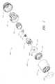
- FIG. 1is an exploded perspective view of an insertion device and an insertion set according to one embodiment.
- FIG. 2is an assembled perspective view of the insertion device of FIG. 1 .
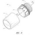
- FIG. 3illustrates a protective cap removed from an actuator of the insertion device of FIG. 1 .
- FIG. 4is a side view of the actuator of the insertion device of FIG. 1 .
- FIG. 5is a lower perspective view of the actuator of FIG. 5 .
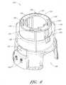
- FIG. 6is an upper perspective view of the sleeve of the insertion device of FIG. 1 .
- FIG. 7is a lower perspective view of the sleeve of FIG. 6 .
- FIG. 8is a lower perspective view of a needle and needle hub of the insertion device of FIG. 1 .
- FIG. 9is an upper perspective view of a shuttle of the insertion device of FIG. 1 .
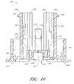
- FIG. 10is a cross-sectional view of the shuttle of FIG. 9 , taken along line 10 - 10 shown in FIG. 9 .
- FIG. 11is a cross-sectional view of the shuttle of FIGS. 9 and 10 , taken along line 11 - 11 shown in FIG. 9 .
- FIG. 12is an upper perspective view of a protective cap for use with an insertion device.
- FIG. 13is an upper perspective view of the protective cap of FIG. 12 , showing a portion of an infusion device accommodated therein.
- FIG. 14is a cross-sectional view of the insertion device of FIG. 1 before actuation, taken along line 14 - 14 shown in FIG. 3 .
- FIG. 15is another cross-sectional view of the insertion device in FIG. 1 before actuation, taken along line 15 - 15 shown in FIG. 14 .
- FIG. 16is a cross-sectional view, similar to FIG. 15 , of the insertion device of FIG. 1 after actuation.
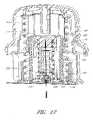
- FIG. 17is another cross-sectional view, similar to FIG. 14 , of the insertion device of FIG. 1 after actuation.
- FIG. 18is an exploded perspective view of an insertion device and an insertion set according to one embodiment.
- FIG. 19is an assembled perspective view of the insertion device of FIG. 18 .
- FIG. 20is a perspective view of an actuator of the insertion device of FIG. 18 .
- FIG. 21is a lower perspective view of the actuator of FIG. 20 .
- FIG. 22is an upper perspective view of a sleeve of the insertion device of FIG. 18 .
- FIG. 23is a lower perspective view of the sleeve of FIG. 22 .
- FIG. 24is an upper perspective view of a needle hub of the insertion device of FIG. 18 .
- FIG. 25is an upper perspective view of the shuttle of the insertion device of FIG. 18 .
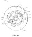
- FIG. 26is a lower perspective view of the shuttle of FIG. 25 .
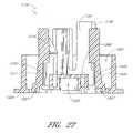
- FIG. 27is a cross-sectional view of the shuttle of FIGS. 25 and 26 , taken along line 27 - 27 shown in FIG. 25 .
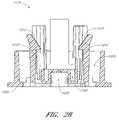
- FIG. 28is another cross-sectional view of the shuttle of FIGS. 25 and 26 , taken along the line 28 - 28 , shown in FIG. 25 .
- FIG. 29is a cross-sectional view, similar to FIG. 27 , of the insertion device of FIG. 18 before actuation.
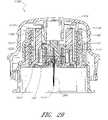
- FIG. 30is a cross-sectional view, similar to FIGS. 27 and 29 , of the insertion device of FIG. 18 after actuation.
- FIG. 1illustrates an embodiment of an insertion device 100 for an infusion device 102 , such as infusion set.
- infusion device 102such as infusion set.
- FIG. 1illustrates an embodiment of an insertion device 100 for an infusion device 102 , such as infusion set.
- infusion devicesincluding infusion sets, are provided in United States Patent Application Publication Nos. 2005/0107743 and 2007/0185441, both of which are hereby incorporated by reference herein in their entireties.
- infusion devicessuch as infusion sets, that may be inserted using insertion devices, and the foregoing publications are provided merely to illustrate some infusion devices that can be used with or adapted to be used with the insertion devices described herein.
- the insertion device 100can comprise an actuator 104 , a sleeve 106 , an insertion spring 108 , a needle hub 110 , a needle 112 , a retraction spring 114 , a shuttle or carriage 116 , a protective cap 118 , and a cover 120 .
- the infusion device 102can be an infusion set, and can comprise a base 122 and a tubing set 124 .
- the base 122can comprise a soft cannula 264 and an adhesive sheet 266 .
- the tubing setcan comprise an infusion cap 240 , a length of tubing 250 , and a connector 254 (see FIG. 13 ).
- the infusion device 102can be packaged within the insertion device 100 .
- FIG. 2illustrates the insertion device 100 in an assembled state with the protective cap 118 engaged with the actuator 104 .
- the protective cap 118can be removed from the actuator 104 , as shown in FIG. 3 , in preparation for insertion of the base 122 .
- the insertion device 100may omit the cap 118 .
- the actuator 104can include one or more gripping surfaces 126 , one or more pushing surfaces 130 , one or more arms 134 having feet 136 , and a coupling region 140 .
- the actuator 104can be made of a rigid plastic, such as ABS (acrylonitrile butadiene styrene), polycarbonate, polyethylene, or PET (polyethylene terephthalate).
- the gripping surface 126can extend entirely or partially around the circumference of the actuator 104 or may alternatively be located on opposite sides of the actuator 104 or otherwise spaced on the actuator 104 .
- the gripping surface 126preferably has a dimension, such as an external diameter, that is sufficiently large to facilitate easy grasping by diabetics who have lost dexterity and strength due to diabetic neuropathy. In embodiments having multiple gripping surfaces 126 , the gripping surfaces can be spaced apart by a distance for facilitate easy grasping.
- the gripping surface(s) 126can also have sufficient surface area and be positioned to allow a user to hold the actuator 104 at the gripping surface(s) 126 using the middle section of a user's fingers and/or palm.
- the gripping surface 126can include a plurality of ridges or other surface elements 128 .
- Surface elements 128can increase friction or interface between a user's fingers and the actuator 104 to improve the user's ability to securely hold the actuator 104 .
- the surface elements 128can comprise one or more of texturing, dimples, bumps, grooves, or other surface shapes.
- the surface elements 128can be integrally formed with one or more other portions of the actuator 104 , or may be separately formed and attached by mechanical coupling, such as by interference fit, or by any known bonding technique, such as adhesives.
- the pushing surfaces 130 , 132 of the actuator 104can comprise one or more upper pushing surfaces 130 and/or one or more lower pushing surfaces 132 that can be sized and positioned to be contacted by a user's fingers and/or palm.
- the upper pushing surface 130can be configured to be contacted primarily by a user's palm, while lower pushing surfaces 132 can be configured to be contacted primarily by a user's fingers.
- the upper pushing surface 130is generally convexly domed and the lower pushing surface 132 is generally concave.
- the actuatorcan comprise one or more arms 134 which can have feet 136 .
- the feet 136may be located at or near a terminal end of arms 134 .
- the feetcan include a cam surface 138 and may face outwardly, as illustrated in FIG. 4 , inwardly or circumferentially or in other directions.
- the actuator 104may omit the arms, feet, and cam surfaces.
- the actuator 104can comprise other features.
- the coupling region 140may facilitate secure attachment of the actuator 104 with the protective cap 118 (see FIGS. 1 and 2 ).
- the coupling region 140can comprise a groove 142 which can securely engage a complementary structure of the protective cap 118 , while also allowing easy removal of the protective cap 118 from the actuator 104 .
- the coupling region 140can additionally or alternatively comprise a ridge which can securely engage a complementary structure of the protective cap 118 , while also allowing easy removal of the protective cap 118 from the actuator 104 .
- the actuator 104can comprise a number of features in an interior of the actuator 104 .
- the actuator 104can comprise one or more displacement members 144 , one or more guideposts 148 , and a travel-limiting member 152 .
- Some or all of the displacement members 144 , the guideposts 148 , and the travel-limiting member 152can extend downwardly from the underside of the actuator 104 .
- the displacement member 144can include an engagement surface 146 .
- One or more of the guideposts 148may include a stop surface 150 .
- the travel-limiting member 152may be cylindrical, or may have other configurations, such as square, triangular, frustoconical, or actuate.
- the sleeve 106can comprise an upper surface 154 .
- the upper surface 154can include one or more apertures 156 that are sized and positioned to cooperate with the guideposts 148 of the actuator 104 .
- the apertures 156can be formed in a surface of the sleeve other than the upper surface 154 .
- the apertures 156can comprise recesses formed in the sleeve 106 , such as in the upper surface 154 , in a side surface, or both.
- the sleeve 106can comprise one or more external guide rails 158 and/or one or more internal guide rails 160 .
- the external guide rails 158are preferably sized and configured to cooperate with one or more interior surfaces of the actuator 104 , such as interior surface 260 (see FIG. 5 ).
- the external guide rails 158can slidingly engage the interior surface 260 of the actuator 104 to cause the actuator 104 and the sleeve 106 to move along a generally straight path with respect to one another.
- the external guide rails 158can additionally or alternatively cooperate with one or more interior surfaces of the actuator 104 to allow the cap 104 and the sleeve 106 to rotate with respect to each other.
- the external guide rails 158may extend generally linearly (e.g., straight), as shown in FIG. 6 , though the external guide rails 158 may also have other configurations.
- the internal guide rails 160can be sized and configured to cooperate with appropriate structures of the shuttle 116 , discussed below.
- the internal guide rails 160can extend longitudinally, as shown on FIG. 6 , or may have other configurations. In some embodiments, the internal guide rails 160 are arranged in pairs to define a channel therebetween.
- the sleeve 106can also comprise a recess 168 .
- the recess 168can permit one or more portions of the infusion device 102 to extend therethrough (see FIGS. 14 and 17 ).
- the sleeve 106can comprise one or more apertures 166 that can be used to facilitate molding internal features of the sleeve 106 .
- the sleeve 106can also comprise a stop ledge 262 , the purpose of which is described further below in connection with FIGS. 14-17 .
- the sleeve 106can comprise one or more apertures 162 that are configured to permit the arms 134 of the actuator 104 (see FIG. 4 ) to extend therethrough.
- the aperture 162can have a width that allows the arm 134 to move within the aperture 162 as the actuator 104 is rotated with respect to sleeve 106 between a locked position and an unlocked position.
- the stop surfaces 150 of the actuator 104can be positioned over the upper surface 154 of the sleeve 106 to prevent movement of the actuator 104 relative to the sleeve 106 toward the skin.
- the sleeve 106can also comprise indicia 164 to indicate whether the actuator 104 and sleeve 106 are in the unlocked or locked position.
- the sleeve 106can comprise a recess 170 in which the one or more feet 136 of the actuator 134 may move.
- the recess 170can be bounded on one side by a shoulder 172 that is configured to engage the one or more feet 136 of the actuator 104 .
- the shoulder 172can comprise a protrusion 174 to prevent unintentional rotation of the actuator 104 with respect to sleeve 106 between the locked position and the unlocked position.
- the protrusion 174can also provide tactile feedback to a user when the actuator 104 is moved with respect to the sleeve 106 between the locked position and the unlocked position.
- the sleeve 106can also comprise a lower surface 176 .
- the lower surface 176can be configured to provide stable contact with a person's skin during placement of the base 122 of the infusion device 102 into the person's skin.
- the lower surface 176can be continuous, as illustrated in FIG. 7 , or segmented.
- the sleeve 106can comprise a recess 178 (see, e.g., FIGS. 15 and 16 ) to receive all or a portion of the insertion spring 108 therein.
- the sleeve 106can comprise a cam surface 180 .
- the cam surface 180can be cylindrical, as illustrated in FIG. 7 , or have other configurations.
- the cam surface 180can have a generally circular cross-section, as illustrated in FIG. 7 , or can have other cross-sectional shapes such as polygonal.
- the cam surface 180can form a closed loop as shown in FIG. 7 , or may not form a closed loop, but instead comprise one or more longitudinal cam surfaces.
- the sleeve 106can be made of a rigid plastic, such as ABS, polycarbonate, polyethylene, or PET.
- the needle hub 110can comprise an upper side 182 and a lower side 184 .
- the lower side 184can comprise a needle-mounting aperture 186 and a recess 188 .
- the recess 188can be configured to receive all or a portion of the retraction spring 114 (see FIGS. 1 and 14 - 17 ).
- the needle hubcan also include one or more engagement surfaces 190 and a follower surface 192 .
- the needle hub 110can be made of a rigid plastic, such as ABS, polycarbonate, polyethylene, or PET. As shown in FIGS. 14-17 , a horizontal cross-sectional area of the needle hub 100 can be constant between the retracted and advanced positions of the hub.
- the needle 112can be inserted into and fixed within the needle-mounting aperture 186 of the needle hub 110 .
- the needle 112can be fixed to the needle hub 110 by any suitable adhesive, such as a solvent adhesive.
- the needle 112can include a beveled end 194 .
- the needle 112can be made of a suitable metal, such as stainless steel.
- the shuttle 116can include recesses 202 that are configured to receive at least a portion of the insertion spring 108 (see FIGS. 14-17 ).
- the insertion spring 108can engage the sleeve 106 , and the insertion spring 108 can bias the shuttle 116 from the sleeve 106 .
- the guideposts 148can extend through the apertures 156 in the sleeve 106 ( FIG. 6 ), and the insertion spring can engage the guideposts 148 to bias the actuator from the shuttle 116 (see FIGS. 14-15 ).
- the shuttle 116can include one or more sleeve-engaging arms 196 , each having a sleeve-engaging foot 198 .
- the sleeve-engaging arms 196 of the shuttle 116can be biased so that the sleeve-engaging feet 198 rest upon the upper surface 154 of the sleeve 106 to maintaining the insertion spring 108 in a compressed state (see FIG. 14 ).
- the sleeve-engaging feet 198 and upper surface 154are preferably configured to align with the displacement member 144 of the actuator 144 so that the engagement surface 146 of the displacement member 144 aligns with cam surfaces 200 of the sleeve-engaging feet 198 .
- movement of the displacement member 144 against the feet 198can cause the feet 198 to disengage from the upper surface 154 of the sleeve 106 .
- the cam surfaces 200 of the sleeve-engaging feet 198can be beveled, as shown in FIGS. 9-10 and 14 , or alternatively the engagement surface 146 can be beveled.
- the shuttle 116can be configured to accommodate the needle hub 110 and needle 112 .
- the shuttle 116can comprise one or more cam surfaces 204 configured to cooperate with the follower surface 192 of the needle hub 110 to orient the needle hub 110 while permitting sliding movement of the needle hub 110 relative to the shuttle 116 .
- the shuttle 116can also comprise a needle aperture 206 to permit the needle 110 to extend therethrough.
- the shuttle 116can comprise one or more recesses 208 to receive at least a portion of the retraction spring 114 .
- the retraction springalso can engage the needle hub 110 , at the recess 188 for example, and the retraction spring 114 can bias the needle hub 110 from the shuttle 116 (see FIGS. 14-17 ).
- the shuttle 116can include one or more needle-hub-engaging arms 210 , each having a needle-hub-engaging foot 212 .
- the needle-hub-engaging arms 210can be biased away from the needle hub 110 to allow the needle hub 110 to move freely along the guide surfaces 204 .
- the needle hub 110can be forced toward the shuttle 116 to compress the retraction spring 114 (see FIGS. 14 and 15 ).
- the needle-hub-engaging arms 210can then be forced together so that the needle-hub-engaging feet 212 engage the upper side 182 of the needle hub 110 to restrict movement of the needle hub 110 away from the shuttle 116 . As shown in FIG.
- the needle hub 110can be positioned in an internal cavity 207 having a horizontal cross-sectional area, and a horizontal cross-sectional area of the needle hub 110 (see FIGS. 14 and 15 ) can be smaller than a horizontal cross-section of the internal cavity 207 .
- the needle-hub-engaging arms 210can also comprise a follower surface 214 (see FIG. 11 ) that cooperates with the cam surface 180 of the sleeve 106 to prevent the needle-hub-engaging arms 210 from spreading apart to release the needle hub 210 (see FIGS. 15 and 16 ).
- the shuttle 116can comprise guide surfaces 216 that are sized in positioned to cooperate with the can surface 180 of the sleeve 106 to orient of the shuttle 116 relative to the sleeve 106 as the shuttle 116 moves away from the sleeve 106 under the force of the insertion spring 108 .
- the shuttle 116can comprise slots 218 that are sized and configured to cooperate with internal guide rails 160 of the sleeve 106 to inhibit or prevent rotation of the shuttle 116 relative to the sleeve 106 and guide the movement of the sleeve-engaging arms 196 and sleeve-engaging feet 198 .
- the shuttle 116can comprise a recess 220 to receive at least a portion of an infusion device 102 .
- the recess 220can be positioned such that the needle 112 extends through the needle apertures 206 and through the cannula 264 of the base 122 .
- the shuttle 116can also comprise additional surfaces such as surfaces 222 and 224 , to engage the infusion device 102 .
- the shuttle 116can comprise one or more base-retaining arms 226 .
- the base-retaining arms 226can extend into the recess 220 to engage the infusion device 102 .
- the arms 226can include set-engagement surfaces 228 that may include features, such as ribs 230 , to frictionally engage the base 122 .
- the set-engagement surfaces 228can be substantially flat or in other embodiments can be concave or have other shapes.
- the arms 226can include surfaces 232 positioned for engagement by the needle hub 110 to force the set-engagement surfaces 228 into contact with the infusion device 102 to prevent the infusion device 102 from unintentional disengagement from the shuttle 116 .
- the engagement surface 190 of the needle hub 110can press against the engagement surfaces 232 to move the arms 226 and thereby squeeze the infusion device 102 between the set-engagement surfaces 228 within the recess 220 .
- the shuttle 116can be made of a rigid plastic, such as ABS, polycarbonate, polyethylene, or PET. Nonetheless, it can be advantageous for the material from which the shuttle 116 is made to have sufficient memory to properly function as described herein.
- the protective cap 118can comprise a cylindrical wall 234 of sufficiently large width, diameter, or length, to accommodate therein the tubing set 124 as illustrated in FIG. 13 .
- the protective cap 118can include a plurality of apertures 236 to facilitate the sterilization of the insertion device 100 and/or the infusion device 102 .
- the cover 120(see FIGS. 1-3 ) can be applied to the protective cap 118 to cover the apertures 236 before or after sterilization of the insertion device 100 and/or the infusion device 102 .
- the cover 120can be made of DuPont Tyvek® or other suitable material.
- the protective cap 118can comprise one or more structures to receive and retain the tubing set 124 of the infusion device 102 .
- the protective cap 118can comprise one or more receiving structures 238 to receive the infusion cap 240 and one or more arms 242 having feet 244 to hold the infusion cap 240 securely within the protective cap 118 .
- the protective cap 118can include a plurality of arms 246 having feet 248 that are configured to hold the length of tubing 250 .
- One of the arms 246can also comprise a recess 252 to receive the connector 254 .
- the protective cap 118can comprise a recess 256 to receive a portion of the connector 254 so that the connector 254 can be held securely between the recess 256 and the arm 246 that includes the recess 252 .
- the protective cap 118can comprise a coupling region 258 configured to cooperate with the coupling region 140 of the actuator 104 .
- the protective cap 118can be made of a rigid plastic or a semi-rigid plastic, such as ABS, polycarbonate, polyethylene, or PET. In some embodiments, it may be desirable for the actuator 104 and the protective cap 118 to be made of different materials.
- the protective cap 118can be made of a material that is less rigid than the material of the actuator 104 to facilitate operation of the coupling regions 120 , 258 .
- the protective cap 118can be made of a clear material, such polycarbonate, to facilitate inspection of the infusion device 102 by a manufacturer or user, for example.
- the protective cap 118can advantageously be used for storage and transportation of the tubing set 124 .
- the protective cap 118can also be used as a sterile environment for the infusion cap 240 while the connector 254 is connected to an infusion pump and the tubing set 124 is primed.
- the actuator 104 , the sleeve 106 , the shuttle 116 , and the protective cap 118can be made of any of a variety of plastics known to those of skill in the art, such as those identified above, or may alternatively be made of metal or other materials.
- the insertion spring 108 and the retraction spring 114can be made of plastic, metal, rubber, or other materials. In some embodiments the insertion spring 108 and the retraction spring 114 can be made of steel, such as stainless steel or spring steel.
- the springs 108 and 114may have configurations other than that of a helical spring.
- the insertion device 100 and infusion device 102can be packaged together and transported in the assembled state shown in FIG. 2 .
- a label(not shown) may be applied to the side of the protective cap 118 and the actuator 104 to provide instructions to the user and provide a tamper-evident seal to the insertion device 100 .
- the labelcould be positioned so that the user would need to tear the label before removing the protective cap 118 from the actuator 104 , as shown in FIG. 3 .
- the connector 254 and some or all of the length of tubing 250are removed from the protective cap 118 .
- the connector 254is connected to an infusion pump and then the tubing set 124 is primed.
- the infusion cap 240is kept within the protective cap 118 to preserve the sterility of the infusion cap 240 .
- the userAfter preparing an injection site on the patient's skin, the user removes protective paper backing, if any, from the adhesive of the base 122 .
- the sleeve 106is then rotated relative to the actuator 104 from the locked position to the unlocked position and the lower surface 176 of the sleeve 106 is placed on the skin at the injection site.
- the actuator 104can be advanced toward the skin with the external guide rails 158 , if present, of the sleeve 106 guiding the actuator 104 as it is advanced. Advancement of the actuator 104 toward the sleeve 106 can disengage or permit disengagement the sleeve-engaging feet 198 of the shuttle 116 from the upper surface 154 of the sleeve 106 . For example, referring to FIGS.
- the actuator 104compresses the insertion spring 108 until the engagement surface 146 of the displacement member 144 of the actuator 104 presses against the cam surfaces 200 of the sleeve-engaging feet 198 of the shuttle 116 to force the sleeve-engaging feet 198 off of the upper surface 154 of the sleeve 106 to allow the shuttle 116 to advance within the sleeve 106 .
- the orientation of the shuttle 116 within the sleeve 106can be preserved as the shuttle 116 advances by cooperation of the internal guide rails 160 in cooperation with the slots 218 of the shuttle 116 . Advancement of the shuttle 116 within sleeve 106 can be limited by the engagement of the sleeve-engaging feet 198 against the stop ledge 262 of the sleeve 106 (see FIG. 17 ).
- Movement of the shuttle 116 from a retracted position toward an advanced positioncan permit or can cause the hub 110 to move away from the hub 110 .
- the needle-hub-engaging arms 210can clear the cam surface 180 of the sleeve 106 to allow the needle-hub-engaging arms 210 to move away from the needle hub 110 .
- the retraction spring 114can push the needle hub 110 away from the shuttle 116 to draw the needle 112 within the insertion device 100 , as illustrated in FIGS. 16 and 17 .
- the guide surfaces 204 of the shuttle 116can orient the needle hub 110 as it moves away from the shuttle 116 so that the needle 112 is withdrawn substantially linearly (e.g., straightly) from the skin.
- the needle 112can be protected both before and after insertion of the base 122 to prevent accidental needle sticks.
- This automatic retraction featurecan ensure that the needle 212 is only exposed while the infusion device 102 is being inserted.
- the insertion device 100can be configured to be used only a single time such that the insertion device 100 can be discarded with the needle safely retained therein.
- the surfaces 222 and 224 of the shuttle 116can press the base 122 against the skin. Additionally or alternatively, the surfaces 222 and 224 can inhibit movement of the infusion device 102 away from the skin as the needle 112 is retracted. In embodiments comprising arms 226 (see FIG. 10 ), once the needle hub 110 moves away from the shuttle 116 , pressure can be released from the engagement surface 232 of the arms 226 releasing the set-engagement surfaces 228 from the base 122 so that the base 122 is released from the shuttle 116 .
- the usermay maintain pressure against the cap 104 so that the surfaces 222 and 224 of the shuttle 116 hold a portion of the infusion device 102 , such as the base 122 , against the skin to ensure good adhesion between the infusion device 102 and the skin. Thereafter, the user may lift the insertion device 100 away from the skin leaving the infusion device 102 against the skin with the cannula extending through the skin.
- the protective cap 118can be engaged with the actuator 104 for safe disposal of the needle 112 within the insertion device 100 .
- the insertion device 100can be safely disposed with the needle 112 retracted into the insertion device 100 even if the protective cap 118 is omitted or not engaged with the actuator 104 .
- the insertion device 100can be used to insert an infusion set 102 having a rigid infusion cannula 264 , such as those described in United States Patent Application Publication No. 2007/0185441, which is hereby incorporated by reference herein in its entirety. Such embodiments of the insertion device 100 may omit the needle 112 if the infusion cannula 264 has sufficient rigidity to pierce skin.
- FIG. 18illustrates an embodiment of an insertion device 1100 for an infusion device, such as the infusion device 102 .
- the insertion device 1100is similar in many respects to the insertion device 100 . Therefore, similar components of the insertion device 1100 are referenced by the same reference numeral as the corresponding component in the insertion device 100 incremented by one thousand.
- the insertion device 1100can comprise an actuator 1104 , a sleeve 1106 , an insertion spring 1108 , a needle hub 1110 , a needle 1112 , a retraction spring 1114 , a shuttle 1116 , a protective cap 1118 , and a cover 1120 .
- the infusion device 102can be packaged within the insertion device 1100 .
- the insertion device 1100can differ from the insertion device 100 in some respects.
- the actuator 1104can comprise one or more projections 1107 , illustrated in FIGS. 19 and 20 .
- the projections 1107can extend generally away from one or more gripping surfaces 1126 , one or more pushing surfaces 1130 , or a combination thereof.
- the projections 1107can be spaced substantially evenly around the actuator 1104 or can be otherwise spaced on the actuator 1104 .
- the gripping surfaces 1126can extend between the projections 1107 .
- the projections 1107can provide one or more advantages.
- the projectionsmay aid in the removal of a protective wrapping, covering, or other seal or temper-evidencing feature.
- Insertion devicescan be distributed to end-users in a sealed configuration to maintain the insertion devices in a sterile condition.
- sterilitycan be maintained by distributing the insertion device 100 , 1100 in an assembled state ( FIGS. 3 and 19 ) and by substantially sealing the coupling region 140 , 1140 between the actuator 104 , 1104 and the protective cap 118 , 1118 .
- the coupling region 1140can be wrapped with a layer of plastic or cellophane shrink-wrapping, or a shrink-wrapping formed from any other suitable material.
- the projections 1107can comprise one or more surfaces 1105 , as shown in FIG. 19 , to facilitate removal of the shrink-wrapping, covering, or other seal or temper-evidencing feature from the coupling region 1140 .
- the shrink-wrappingcould be removed by rubbing the surface 1105 against another object, creating a pressure on the shrink-wrapping sufficient to loosen, tear or otherwise remove the shrink wrapping.
- the surfaces 1105may also provide a suitable location for provision of a tab, perforation, or other feature to aid a user in removing a protective wrapping, covering, or other seal or temper-evidencing feature. Additionally or alternatively, the projections 1107 may aid manipulation of the actuator 1104 during use or manufacturing by indicating the orientation of the actuator 1104 , providing additional surfaces or surfaces for gripping, or both.
- the actuator 1104can comprise one or more apertures 1163 .
- the actuator 1104can comprise indicia 1165 to indicate whether the actuator 1104 and the sleeve 1106 are in an unlocked position or a locked position.
- an interior of the actuator 1104may comprise one or more displacement members 1144 , one or more guideposts 1148 , one or more travel-limiting members 1152 , and one or more grooves or detents 1171 .
- the detentscan have configurations other than that of grooves.
- the grooves 1171can be positioned adjacent to the one or more apertures 1163 .
- the sleeve 1106can comprise one or more arms 1135 .
- Each arm 1135can comprise a foot 1137 .
- the feet 1137can be located at a terminal end of the arms 1135 .
- Each footcan include a cam surface 1139 .
- the feet 1137can face outwardly, as illustrated in FIGS. 22 and 23 , inwardly, circumferentially, or in other directions.
- One or more of the arms 1135can comprise a ridge 1175 .
- the ridge 1175can be located centrally on an arm 1135 and can extend partially or entirely from a base of the arm to a terminal end, as shown in FIGS. 22 and 23 .
- the ridge 1175can be located close to an edge of the arm 1135 .
- the ridges 1135 illustrated in FIGS. 22 and 23are primarily straight with constant heights and widths along their lengths, in other embodiments the ridges can be curved or have a non-constant widths or heights.
- the ridgescan be circular and can resemble a single generally circular bump or a series of bump, or have other configurations.
- the one or more apertures 1163 of the actuator 1104can be configured to permit a portion of one or more of the arms 1135 , the feet 1137 , the cam surfaces 1139 , and the ridges 1175 of the sleeve 1106 (see FIGS. 22 and 23 ) to partially or fully extend through the apertures 1163 .
- the one or more apertures 1163can have a width that allows a foot 1137 of the sleeve 1106 to move within the aperture 1163 as the actuator 1104 is rotated with respect to sleeve 1106 between the locked position and the unlocked position.
- the grooves 1171can be configured to accept the ridge 1175 of the arm 1135 when the foot 1137 fully or partially extends through the aperture 1163 .
- Rotation of the foot 1137 along with the arm 1135 relative to the aperture 1163is accompanied by movement of the ridge 1175 relative to the grooves 1171 .
- the locked positioncan be indicated by engagement of the ridge 1175 with one of the grooves 1171
- the unlocked positioncan be indicated by engagement of the ridge 1175 with the other of grooves 1171 .
- the locked positioncan be indicated by proximity of the foot 1137 to one of the indicia 1165 on the actuator 1104 as viewed through one of the apertures 1163 .
- rotation of the arm 1135 relative to the aperture 1163requires more force when the ridge 1175 is engaged with one of the grooves 1171 .
- unintentional rotation of the actuator 1104 with respect to the sleeve 1106can be inhibited, which unintentional rotation may accidentally unlock the device.
- Engagement of the ridge 1175 and one of the grooves 1171can also provide tactile feedback to the user when the actuator 1104 is moved between the locked position and the unlocked position.
- the arm 1135can comprise one or more grooves and the actuator 1104 can comprise one or more ridges with the one or more grooves and the one or more ridges being configured to cooperate.
- Other configurationscan also be used.
- the arm 1135can comprise one or more detents and the actuator 1104 can comprise one or more bumps with the one or more detents and the one or more bumps being configured to cooperate.
- FIG. 24illustrates the needle hub 1110 .
- the needle hub 1110comprises an upper side 1182 , a lower side 1184 , a cylindrical follower surface 1192 , and a protrusion 1183 .
- the protrusion 1183can be positioned on the upper side 1182 , as illustrated in FIG. 24 , or can in other embodiments be located on the lower side 1184 .
- the protrusion 1183may aid in assembling the insertion device 1100 . For example, it may facilitate proper orientation of the needle hub 1110 during assembly of the insertion device 1100 . Additionally or alternatively, the protrusion 1183 may act as a handle for manipulating and stabilizing the needle hub during assembly.
- FIGS. 25-28illustrate the shuttle 1116 .
- the shuttle 1116can comprise one or more recesses 1202 that are configured to receive at least a portion of the insertion spring 1108 .
- the shuttle 1116can comprise one or more sleeve-engaging arms 1196 each having a sleeve-engaging foot 1198 .
- the shuttlecan comprise one or more cam surfaces 1204 configured to cooperate with the follower surface 1192 of the needle hub 1110 to orient the needle hub 1110 while permitting sliding movement of the needle hub 1110 relative to the shuttle 1116 .
- the shuttle 1116can comprise one or more recesses 1208 to receive at least a portion of the retraction spring 1114 .
- the shuttlecan comprise one or more needle-hub-engaging arms 1210 , each having a needle-hub-engaging foot 1212 .
- the shuttle 116can comprise a recess 1220 to receive at least a portion of an infusion device 102 , such as an infusion set.
- the recess 1220can be positioned such that the needle 1112 extends through the needle aperture 1206 and through the cannula 264 of the base 122 .
- the shuttle 1116can also comprise additional surfaces such as surfaces 1222 and 1224 , to engage the infusion device 102 .
- the shuttle 1116can comprise one or more base-retaining arms 1226 , such as those illustrated in FIGS. 25-28 , to engage the infusion device 102 .
- the base-retaining arms 1226can be positioned in base-retaining arm recesses 1221 .
- the arms 1226can include base-retaining feet 1227 , to clamp, grasp, or otherwise engage the base 122 and secure it to the shuttle 1116 .
- the base-retaining feet 1227can be substantially flat or in other embodiments can be concave or have other shapes.
- the base-retaining arms 1226can include sleeve-engagement surfaces 1233 positioned for engagement by the cam surface 1180 of the sleeve 1106 to urge the base-retaining feet 1227 toward the base 122 to impede unintentional disengagement of the infusion device 102 from the shuttle 1116 .
- the base-retaining feet 1227can be configured such that when the cam surface 1180 is engaged with the sleeve-engagement surfaces 1233 , the base-retaining feet 1227 extend beneath a bottom edge of the base 122 , thereby physically inhibiting separation of the infusion device 102 from the shuttle 1116 .
- the insertion device 1100can be used as follows. After preparing an injection site on the skin, the user can remove a protective paper backing, if any, from an adhesive of the base 122 . The sleeve 1106 can then be rotated relative to the actuator 1104 from the locked position to the unlocked position and a lower surface 1176 of the sleeve 1106 can be placed on the skin at the injection site.
- the actuator 1104can be advanced toward the skin, with the external guide rails 1158 of the sleeve 1106 guiding the actuator 1104 as it is advanced.
- the actuator 1104can compress the insertion spring 1108 until an engagement surface 1146 of the displacement member 1144 of the actuator 1104 presses against cam surfaces 1200 of the sleeve-engaging feet 1198 of the shuttle 1116 to force the sleeve-engaging feet 1198 off of an upper surface 1154 of the sleeve 1106 to allow the shuttle 1116 to advance within the sleeve 1106 .
- the orientation of the shuttle 1116 within the sleeve 1106can be preserved as the shuttle 1116 advances by cooperation of internal guide rails 1160 in cooperation with slots 1218 of the shuttle 1116 . Advancement of the shuttle 1116 within sleeve 1106 can be limited by the engagement of the sleeve-engaging feet 1198 against one or more stop ledges 1262 of the sleeve 1106 (see FIG. 30 ).
- the sleeve-engagement surfaces 1233 of the shuttle 1116can advance downwardly relative to the cam surface 1180 of the sleeve 1106 .
- the base-retaining arms 1226can spread outwardly when the sleeve-engagement surfaces 1233 of the shuttle 1116 clear the cam surface 1180 of the sleeve 1106 .
- the base-retaining feet 1227can move away from the base 122 as the base-retaining arms 1126 spread outwardly such that the base 122 can be released from the shuttle 1116 .
- the needle-hub-engaging arms 1210can clear the cam surface 1180 of the sleeve 1106 to allow the needle-hub-engaging arms 1210 to move away from the needle hub 1110 .
- the retraction spring 1114can push the needle hub 1110 away from the shuttle 1116 to draw the needle 1112 within the insertion device 1100 .
- the guide surfaces 1204 of the shuttle 1116can orient the needle hub 1110 as it moves away from the shuttle 1116 so that the needle 1112 can be withdrawn substantially linearly (e.g., straightly) from the patient's skin.
- the needle 1112can be protected both before and after insertion of the base 122 to prevent accidental needle sticks. This automatic retraction feature can ensure that the needle 1212 is only exposed while the infusion device 102 is being inserted.
- Surfaces 1222 or 1224 of the shuttle 1116can press the base 122 against the skin.
- the usermay maintain pressure against the cap 104 so that the surfaces 1222 and 1224 of the shuttle 1116 can hold the base 122 against the skin to ensure good adhesion between the base 122 and the skin. Thereafter, the user may lift the insertion device 1100 away from the skin leaving the base 122 against the skin with the cannula extending through the skin.
- the protective cap 1118can be engaged with the actuator 1104 for safe disposal of the needle 1112 within the insertion device 1100 .
- the insertion device 1100can be used to insert an infusion device 102 , such as an infusion set, having a rigid infusion cannula 264 , such as those described in United States Patent Application Publication No. 2007/0185441, which is hereby incorporated by reference herein in its entirety.
- Such embodiments of the insertion device 1100may omit the needle 1112 if the infusion cannula 264 has sufficient rigidity to pierce the skin.
- the needle hub 1110 and the retraction spring 1114may be omitted. If these components are omitted, corresponding simplifications to the structure of the shuttle 1116 may also be made. Other components, structures, or processes can be omitted in these and other embodiments.
Landscapes
- Health & Medical Sciences (AREA)
- Vascular Medicine (AREA)
- Engineering & Computer Science (AREA)
- Anesthesiology (AREA)
- Biomedical Technology (AREA)
- Heart & Thoracic Surgery (AREA)
- Hematology (AREA)
- Life Sciences & Earth Sciences (AREA)
- Animal Behavior & Ethology (AREA)
- General Health & Medical Sciences (AREA)
- Public Health (AREA)
- Veterinary Medicine (AREA)
- Infusion, Injection, And Reservoir Apparatuses (AREA)
Abstract
Description
Claims (22)
Priority Applications (2)
| Application Number | Priority Date | Filing Date | Title |
|---|---|---|---|
| US12/208,313US8409145B2 (en) | 2007-09-17 | 2008-09-10 | Insertion devices for infusion devices |
| TW097135517ATW200930425A (en) | 2007-09-17 | 2008-09-16 | Insertion devices for infusion devices |
Applications Claiming Priority (3)
| Application Number | Priority Date | Filing Date | Title |
|---|---|---|---|
| US97313407P | 2007-09-17 | 2007-09-17 | |
| US4223208P | 2008-04-03 | 2008-04-03 | |
| US12/208,313US8409145B2 (en) | 2007-09-17 | 2008-09-10 | Insertion devices for infusion devices |
Publications (2)
| Publication Number | Publication Date |
|---|---|
| US20090124979A1 US20090124979A1 (en) | 2009-05-14 |
| US8409145B2true US8409145B2 (en) | 2013-04-02 |
Family
ID=39884514
Family Applications (1)
| Application Number | Title | Priority Date | Filing Date |
|---|---|---|---|
| US12/208,313Expired - Fee RelatedUS8409145B2 (en) | 2007-09-17 | 2008-09-10 | Insertion devices for infusion devices |
Country Status (7)
| Country | Link |
|---|---|
| US (1) | US8409145B2 (en) |
| EP (1) | EP2200677A1 (en) |
| JP (1) | JP2010538751A (en) |
| AU (1) | AU2008302516B2 (en) |
| CA (1) | CA2699875A1 (en) |
| TW (1) | TW200930425A (en) |
| WO (1) | WO2009039013A1 (en) |
Cited By (45)
| Publication number | Priority date | Publication date | Assignee | Title |
|---|---|---|---|---|
| US20110288526A1 (en)* | 2008-11-07 | 2011-11-24 | Min Wei | Pen Needle Assembly For Intradermal Injection |
| US20130060233A1 (en)* | 2011-09-02 | 2013-03-07 | Unitract Syringe Pty Ltd | Insertion mechanism for a drug delivery pump |
| US20160144106A1 (en)* | 2014-11-25 | 2016-05-26 | Medtronic Minimed, Inc. | Infusion set insertion device and method of use |
| EP2549918B1 (en) | 2010-03-24 | 2016-06-29 | Abbott Diabetes Care, Inc. | Medical device inserters and processes of inserting and using medical devices |
| USD785789S1 (en)* | 2013-11-25 | 2017-05-02 | Medline Industries, Inc. | Connector |
| US9707337B2 (en) | 2011-09-13 | 2017-07-18 | Unitract Syringe Pty Ltd | Sterile fluid pathway connection to drug containers for drug delivery pumps |
| US9707335B2 (en) | 2011-09-02 | 2017-07-18 | Unitract Syringe Pty Ltd | Drive mechanism for drug delivery pumps with integrated status indication |
| US9737655B2 (en) | 2013-08-23 | 2017-08-22 | Unitract Syringe Pty Ltd | Integrated pierceable seal fluid pathway connection and drug containers for drug delivery pumps |
| US9802030B2 (en) | 2013-01-25 | 2017-10-31 | Unl Holdings Llc | Integrated sliding seal fluid pathway connection and drug containers for drug delivery pumps |
| US9814832B2 (en) | 2011-09-02 | 2017-11-14 | Unl Holdings Llc | Drive mechanism for drug delivery pumps with integrated status indication |
| USD802760S1 (en)* | 2016-02-18 | 2017-11-14 | Carebay Europe Ltd | Wireless module for a medical injector |
| US20170367630A1 (en)* | 2015-03-11 | 2017-12-28 | Terumo Kabushiki Kaisha | Sensor insertion device and replacement part |
| US9931066B2 (en) | 2011-12-11 | 2018-04-03 | Abbott Diabetes Care Inc. | Analyte sensor devices, connections, and methods |
| US9993188B2 (en) | 2009-02-03 | 2018-06-12 | Abbott Diabetes Care Inc. | Analyte sensor and apparatus for insertion of the sensor |
| US9999727B2 (en) | 2011-09-02 | 2018-06-19 | Unl Holdings Llc | Drive mechanism for drug delivery pumps with integrated status indication |
| US10213139B2 (en) | 2015-05-14 | 2019-02-26 | Abbott Diabetes Care Inc. | Systems, devices, and methods for assembling an applicator and sensor control device |
| US10251996B2 (en) | 2012-08-29 | 2019-04-09 | Unl Holdings Llc | Variable rate controlled delivery drive mechanisms for drug delivery pumps |
| US10674944B2 (en) | 2015-05-14 | 2020-06-09 | Abbott Diabetes Care Inc. | Compact medical device inserters and related systems and methods |
| USD886986S1 (en) | 2013-03-12 | 2020-06-09 | Unl Holdings Llc | Drug delivery pump |
| US10806855B2 (en) | 2014-09-29 | 2020-10-20 | Unl Holdings Llc | Rigid needle insertion mechanism for a drug delivery pump |
| US10863944B2 (en) | 2017-06-23 | 2020-12-15 | Dexcom, Inc. | Transcutaneous analyte sensors, applicators therefor, and associated methods |
| US10898115B2 (en) | 2015-12-30 | 2021-01-26 | Dexcom, Inc. | Transcutaneous analyte sensor systems and methods |
| US10898644B2 (en) | 2011-03-30 | 2021-01-26 | Uno Medical A/S | Subcutaneous inserter device |
| US11033676B2 (en) | 2016-08-08 | 2021-06-15 | Unl Holdings Llc | Drug delivery device and method for connecting a fluid flowpath |
| USD924406S1 (en) | 2010-02-01 | 2021-07-06 | Abbott Diabetes Care Inc. | Analyte sensor inserter |
| USD926325S1 (en) | 2018-06-22 | 2021-07-27 | Dexcom, Inc. | Wearable medical monitoring device |
| US11071478B2 (en) | 2017-01-23 | 2021-07-27 | Abbott Diabetes Care Inc. | Systems, devices and methods for analyte sensor insertion |
| US11160926B1 (en) | 2007-10-09 | 2021-11-02 | Dexcom, Inc. | Pre-connected analyte sensors |
| US11173244B2 (en) | 2011-09-02 | 2021-11-16 | Unl Holdings Llc | Drive mechanism for drug delivery pumps with integrated status indication |
| US11331022B2 (en) | 2017-10-24 | 2022-05-17 | Dexcom, Inc. | Pre-connected analyte sensors |
| US11350862B2 (en) | 2017-10-24 | 2022-06-07 | Dexcom, Inc. | Pre-connected analyte sensors |
| USD961778S1 (en) | 2006-02-28 | 2022-08-23 | Abbott Diabetes Care Inc. | Analyte sensor device |
| USD962446S1 (en) | 2009-08-31 | 2022-08-30 | Abbott Diabetes Care, Inc. | Analyte sensor device |
| US11446434B2 (en) | 2019-02-22 | 2022-09-20 | Deka Products Limited Partnership | Infusion set and inserter assembly systems and methods |
| US11458248B2 (en)* | 2014-04-24 | 2022-10-04 | Becton, Dickinson And Company | Catheter insertion device |
| USD979766S1 (en) | 2005-09-30 | 2023-02-28 | Abbott Diabetes Care Inc. | Analyte sensor device |
| USD982762S1 (en) | 2020-12-21 | 2023-04-04 | Abbott Diabetes Care Inc. | Analyte sensor inserter |
| US11627900B2 (en) | 2003-12-05 | 2023-04-18 | Dexcom, Inc. | Analyte sensor |
| USD1002852S1 (en) | 2019-06-06 | 2023-10-24 | Abbott Diabetes Care Inc. | Analyte sensor device |
| USD1057941S1 (en) | 2022-08-26 | 2025-01-14 | Deka Products Limited Partnership | Patient care assembly component |
| US12239463B2 (en) | 2020-08-31 | 2025-03-04 | Abbott Diabetes Care Inc. | Systems, devices, and methods for analyte sensor insertion |
| US12274548B2 (en) | 2006-10-23 | 2025-04-15 | Abbott Diabetes Care Inc. | Sensor insertion devices and methods of use |
| US12318200B2 (en) | 2008-11-07 | 2025-06-03 | Dexcom, Inc. | Analyte sensor |
| USD1090862S1 (en) | 2022-08-26 | 2025-08-26 | Deka Products Limited Partnership | Adhering assembly for medical devices and the like |
| US12408847B2 (en) | 2018-06-07 | 2025-09-09 | Abbott Diabetes Care Inc. | Focused sterilization and sterilized sub-assemblies for analyte monitoring systems |
Families Citing this family (96)
| Publication number | Priority date | Publication date | Assignee | Title |
|---|---|---|---|---|
| US7381184B2 (en) | 2002-11-05 | 2008-06-03 | Abbott Diabetes Care Inc. | Sensor inserter assembly |
| USD902408S1 (en) | 2003-11-05 | 2020-11-17 | Abbott Diabetes Care Inc. | Analyte sensor control unit |
| US7883464B2 (en) | 2005-09-30 | 2011-02-08 | Abbott Diabetes Care Inc. | Integrated transmitter unit and sensor introducer mechanism and methods of use |
| US10226207B2 (en) | 2004-12-29 | 2019-03-12 | Abbott Diabetes Care Inc. | Sensor inserter having introducer |
| US9259175B2 (en) | 2006-10-23 | 2016-02-16 | Abbott Diabetes Care, Inc. | Flexible patch for fluid delivery and monitoring body analytes |
| US9398882B2 (en) | 2005-09-30 | 2016-07-26 | Abbott Diabetes Care Inc. | Method and apparatus for providing analyte sensor and data processing device |
| US20090105569A1 (en) | 2006-04-28 | 2009-04-23 | Abbott Diabetes Care, Inc. | Introducer Assembly and Methods of Use |
| US8333714B2 (en) | 2006-09-10 | 2012-12-18 | Abbott Diabetes Care Inc. | Method and system for providing an integrated analyte sensor insertion device and data processing unit |
| US7697967B2 (en) | 2005-12-28 | 2010-04-13 | Abbott Diabetes Care Inc. | Method and apparatus for providing analyte sensor insertion |
| EP1762259B2 (en) | 2005-09-12 | 2025-01-01 | Unomedical A/S | Inserter for an infusion set with a first and second spring units |
| US11298058B2 (en) | 2005-12-28 | 2022-04-12 | Abbott Diabetes Care Inc. | Method and apparatus for providing analyte sensor insertion |
| WO2007098771A2 (en) | 2006-02-28 | 2007-09-07 | Unomedical A/S | Inserter for infusion part and infusion part provided with needle protector |
| CA2653764A1 (en) | 2006-06-09 | 2007-12-13 | Unomedical A/S | Mounting pad |
| JP2009545341A (en) | 2006-08-02 | 2009-12-24 | ウノメディカル アクティーゼルスカブ | Cannula and delivery device |
| ES2820335T3 (en) | 2007-04-16 | 2021-04-20 | Corium Inc | Solvent Cast Microneedle Arrays Containing Active Agent |
| US8456301B2 (en) | 2007-05-08 | 2013-06-04 | Abbott Diabetes Care Inc. | Analyte monitoring system and methods |
| US8160900B2 (en) | 2007-06-29 | 2012-04-17 | Abbott Diabetes Care Inc. | Analyte monitoring and management device and method to analyze the frequency of user interaction with the device |
| USD675316S1 (en)* | 2007-08-22 | 2013-01-29 | Novo Nordisk A/S | Needle hub |
| WO2009048607A1 (en) | 2007-10-10 | 2009-04-16 | Corium International, Inc. | Vaccine delivery via microneedle arrays |
| USD635669S1 (en)* | 2007-11-30 | 2011-04-05 | Terumo Kabushiki Kaisha | Cap for puncture needle chip |
| ATE522240T1 (en) | 2008-02-13 | 2011-09-15 | Unomedical As | SEAL BETWEEN A CANNULAR PART AND A FLUID PATH |
| US9566384B2 (en) | 2008-02-20 | 2017-02-14 | Unomedical A/S | Insertion device with horizontally moving part |
| US8728024B2 (en) | 2008-10-10 | 2014-05-20 | Deka Products Limited Partnership | Infusion pump methods, systems and apparatus |
| US12370327B2 (en) | 2008-10-10 | 2025-07-29 | Deka Products Limited Partnership | Infusion pump methods, systems and apparatus |
| AU2009331635A1 (en) | 2008-12-22 | 2011-06-23 | Unomedical A/S | Medical device comprising adhesive pad |
| WO2011014492A1 (en)* | 2009-07-29 | 2011-02-03 | Smiths Medical Asd, Inc. | Device and method for insertion of a cannula of an infusion device |
| AU2010277755A1 (en) | 2009-07-30 | 2012-02-02 | Unomedical A/S | Inserter device with horizontal moving part |
| KR20120047896A (en) | 2009-08-07 | 2012-05-14 | 우노메디컬 에이/에스 | Delivery device with sensor and one or more cannulas |
| ATE553800T1 (en) | 2009-11-26 | 2012-05-15 | Hoffmann La Roche | EXTERNALLY TRIGGERABLE CANNULA ARRANGEMENT |
| KR20130018783A (en)* | 2010-03-30 | 2013-02-25 | 우노메디컬 에이/에스 | Medical device |
| WO2011140274A2 (en) | 2010-05-04 | 2011-11-10 | Corium International, Inc. | Method and device for transdermal delivery of parathyroid hormone using a microprojection array |
| US11064921B2 (en) | 2010-06-29 | 2021-07-20 | Abbott Diabetes Care Inc. | Devices, systems and methods for on-skin or on-body mounting of medical devices |
| EP2433663A1 (en)* | 2010-09-27 | 2012-03-28 | Unomedical A/S | Insertion system |
| EP2436412A1 (en) | 2010-10-04 | 2012-04-04 | Unomedical A/S | A sprinkler cannula |
| US8919452B2 (en) | 2010-11-08 | 2014-12-30 | Baker Hughes Incorporated | Casing spears and related systems and methods |
| US8795234B2 (en)* | 2010-11-30 | 2014-08-05 | Becton, Dickinson And Company | Integrated spring-activated ballistic insertion for drug infusion device |
| US8814831B2 (en) | 2010-11-30 | 2014-08-26 | Becton, Dickinson And Company | Ballistic microneedle infusion device |
| US8784383B2 (en) | 2010-11-30 | 2014-07-22 | Becton, Dickinson And Company | Insulin pump dermal infusion set having partially integrated mechanized cannula insertion with disposable activation portion |
| US8998851B2 (en) | 2011-02-09 | 2015-04-07 | Becton, Dickinson And Company | Compact spring inserter for drug deliver infusion set |
| ES2868232T3 (en)* | 2011-02-09 | 2021-10-21 | Becton Dickinson Co | Self Contained Inserter for Drug Delivery Infusion Set |
| CA2826094C (en) | 2011-02-09 | 2020-11-10 | Becton, Dickinson And Company | Subcutaneous infusion device |
| IL212263A (en)* | 2011-04-11 | 2014-01-30 | Alexander Kalnitskiy | Intraosseous device for inserting a cannula into a bone |
| WO2013050277A1 (en) | 2011-10-05 | 2013-04-11 | Unomedical A/S | Inserter for simultaneous insertion of multiple transcutaneous parts |
| EP2583715A1 (en) | 2011-10-19 | 2013-04-24 | Unomedical A/S | Infusion tube system and method for manufacture |
| US9440051B2 (en) | 2011-10-27 | 2016-09-13 | Unomedical A/S | Inserter for a multiplicity of subcutaneous parts |
| KR20140135736A (en) | 2012-03-12 | 2014-11-26 | 유니트랙트 시린지 피티와이 엘티디 | Fill-finish cartridges for sterile fluid pathway assemblies and drug delivery devices incorporating fill-finish cartridges |
| EP4406568A3 (en) | 2012-03-30 | 2024-10-16 | Insulet Corporation | Fluid delivery device with transcutaneous access tool, insertion mechanism and blood glucose monitoring for use therewith |
| EP2650031A1 (en)* | 2012-04-11 | 2013-10-16 | PharmaSens AG | Manual pressure activated application mechanism |
| BR112015000541A2 (en)* | 2012-07-11 | 2017-08-08 | Unitract Syringe Pty Ltd | insertion mechanism, drug delivery pump and method of operating an insertion mechanism |
| USD745142S1 (en) | 2012-08-30 | 2015-12-08 | Unitract Syringe Pty Ltd | Drug delivery pump |
| US9731069B2 (en) | 2012-09-27 | 2017-08-15 | Becton, Dickinson And Company | Perpendicular infusion set and disposable inserter |
| BR112015014969B1 (en) | 2012-12-21 | 2021-12-07 | Corium, Inc | MICROSTRUCTURE APPARATUS AND METHOD OF MANUFACTURING A MICROSTRUCTURE APPARATUS |
| EP2968887B1 (en) | 2013-03-12 | 2022-05-04 | Corium, Inc. | Microprojection applicators |
| USD732162S1 (en)* | 2013-03-14 | 2015-06-16 | Eli Lilly And Company | Automatic injection device |
| AU2014233541B2 (en) | 2013-03-15 | 2018-11-22 | Corium Pharma Solutions, Inc. | Microarray for delivery of therapeutic agent, methods of use, and methods of making |
| CA2903763C (en) | 2013-03-15 | 2021-11-16 | Corium International, Inc. | Microarray with polymer-free microstructures, methods of making, and methods of use |
| ES2939317T3 (en) | 2013-03-15 | 2023-04-20 | Corium Pharma Solutions Inc | Multi-impact micro-spray applicators |
| BR112015022625B1 (en) | 2013-03-15 | 2023-01-31 | Corium, Inc | MICROSTRUCTURE DEVICE FOR DELIVERY OF THERAPEUTIC AGENT |
| US10260485B1 (en)* | 2013-10-02 | 2019-04-16 | Flextronics Ap, Llc | Telescoping spring |
| US10624843B2 (en) | 2014-09-04 | 2020-04-21 | Corium, Inc. | Microstructure array, methods of making, and methods of use |
| WO2016065190A1 (en) | 2014-10-23 | 2016-04-28 | Abbott Diabetes Care Inc. | Electrodes having at least one sensing structure and methods for making and using the same |
| TWD174176S (en) | 2014-11-07 | 2016-03-01 | 優尼翠克注射器有限公司 | Portion of drug delivery device (2) |
| USD794770S1 (en) | 2015-06-26 | 2017-08-15 | Unitract Syringe Pty Ltd | Drug delivery pump |
| WO2017004067A1 (en) | 2015-06-29 | 2017-01-05 | Corium International, Inc. | Microarray for delivery of therapeutic agent, methods of use, and methods of making |
| USD794771S1 (en) | 2015-07-10 | 2017-08-15 | Unitract Syringe Pty Ltd. | Drug delivery pump |
| US10576207B2 (en) | 2015-10-09 | 2020-03-03 | West Pharma. Services IL, Ltd. | Angled syringe patch injector |
| US10413665B2 (en) | 2015-11-25 | 2019-09-17 | Insulet Corporation | Wearable medication delivery device |
| JP6885960B2 (en) | 2016-01-21 | 2021-06-16 | ウェスト ファーマ サービシーズ イスラエル リミテッド | Drug delivery device with visual indicators |
| EP3416704B1 (en)* | 2016-02-16 | 2022-11-09 | DEKA Products Limited Partnership | Infusion set and inserter assembly |
| US20170290535A1 (en)* | 2016-04-08 | 2017-10-12 | Medtronic Minimed, Inc. | Analyte sensor with indicators |
| US12419547B2 (en) | 2016-04-08 | 2025-09-23 | Medtronic Minimed, Inc. | Sensor and transmitter product |
| US10765369B2 (en) | 2016-04-08 | 2020-09-08 | Medtronic Minimed, Inc. | Analyte sensor |
| EP4442297A3 (en) | 2016-04-29 | 2025-01-01 | ICU Medical, Inc. | Subcutaneous insertion systems, devices and related methods |
| TWI746569B (en) | 2016-06-08 | 2021-11-21 | 瑞士商瑞健醫療股份有限公司 | Dosiergerat, injektionsvorrichtung und verwendung |
| US10695487B2 (en) | 2016-08-30 | 2020-06-30 | Unl Holdings Llc | Controlled delivery drive mechanisms for drug delivery pumps |
| KR101928297B1 (en)* | 2016-09-08 | 2018-12-12 | 이오플로우(주) | Medical fluid delivery device |
| US11253652B2 (en) | 2016-11-28 | 2022-02-22 | Shl Medical Ag | Device for dispensing a substance |
| US11344709B2 (en)* | 2016-12-16 | 2022-05-31 | Sorrento Therapeutics, Inc. | Fluid delivery apparatus having a controller assembly and method of use |
| WO2018151750A1 (en) | 2017-02-14 | 2018-08-23 | West Pharma. Services IL, Ltd. | Simplified and/or one-handed use of a patch injector |
| WO2018156548A1 (en) | 2017-02-22 | 2018-08-30 | Insulet Corporation | Needle insertion mechanisms for drug containers |
| EP3618712A1 (en) | 2017-05-03 | 2020-03-11 | Abbott Diabetes Care Inc. | Systems, devices, and methods with duration-based adjustment of sensor data |
| EP3687600B1 (en)* | 2017-09-26 | 2022-04-27 | Insulet Corporation | Needle mechanism module for drug delivery device |
| WO2019087183A1 (en)* | 2017-10-30 | 2019-05-09 | Ziv Goldin | Low profile intuitive pharmaceutical injection device |
| US11147931B2 (en) | 2017-11-17 | 2021-10-19 | Insulet Corporation | Drug delivery device with air and backflow elimination |
| US11918348B2 (en) | 2017-12-05 | 2024-03-05 | Abbott Diabetes Care Inc. | Medical devices having a dynamic surface profile and methods for production and use thereof |
| EP4218567B1 (en) | 2018-06-07 | 2025-03-12 | Abbott Diabetes Care, Inc. | Focused sterilization and sterilized sub-assemblies for analyte monitoring systems |
| CN112292166B (en)* | 2018-09-22 | 2023-02-21 | 艾斯曲尔医疗公司 | Syringe Needle Insertion and Retraction Assembly |
| US12403247B2 (en)* | 2019-05-17 | 2025-09-02 | Medtrum Technologies Inc. | Drug infusion device |
| CA3180472A1 (en)* | 2020-05-28 | 2021-12-02 | Eli Lilly And Company | Shift-head inserter device with automatic insertion and retraction |
| US12335342B2 (en) | 2020-07-21 | 2025-06-17 | Abbott Diabetes Care Inc. | Transmitting analyte data using low-power instruction sets |
| FR3112961B1 (en)* | 2020-07-28 | 2022-12-02 | Nemera La Verpilliere | Device for inserting a needle for dispensing a product into a site |
| WO2022047411A1 (en) | 2020-08-31 | 2022-03-03 | Abbott Diabetes Care Inc. | Secured communications in medical monitoring systems |
| TWI745098B (en)* | 2020-09-25 | 2021-11-01 | 群康生技股份有限公司 | Needle out mechanism |
| AU2022316124A1 (en) | 2021-07-21 | 2024-01-18 | Abbott Diabetes Care Inc. | Over-the-air programming of sensing devices |
| CN215960185U (en)* | 2021-08-26 | 2022-03-08 | 深圳硅基传感科技有限公司 | applicator |
| WO2023076346A1 (en)* | 2021-10-29 | 2023-05-04 | Eli Lilly And Company | Inserter devices providing manual insertion and automatic retraction |
Citations (107)
| Publication number | Priority date | Publication date | Assignee | Title |
|---|---|---|---|---|
| US3094989A (en) | 1960-06-10 | 1963-06-25 | Int Treuhand A G | Ampulla incorporating an injection syringe |
| US3467088A (en) | 1966-12-22 | 1969-09-16 | Ralph R Robinson | Intrauterine device inserter |
| US3757771A (en) | 1972-01-10 | 1973-09-11 | Biophysics Corp Int | Sterile inserter apparatus |
| US3820542A (en) | 1971-02-11 | 1974-06-28 | Ampoules Inc | Intramuscular injection devices |
| US4068660A (en) | 1976-07-12 | 1978-01-17 | Deseret Pharmaceutical Co., Inc. | Catheter placement assembly improvement |
| US4068659A (en) | 1976-07-12 | 1978-01-17 | Deseret Pharmaceutical Co., Inc. | Catheter placement assembly |
| US4111190A (en) | 1976-11-11 | 1978-09-05 | Jane Plumridge | Medical applicator assembly for chain cystourethrographic procedure |
| US4164224A (en) | 1974-04-03 | 1979-08-14 | Hastings John A | Disposable earlobe piercing device and method for using the same |
| US4205565A (en) | 1978-04-17 | 1980-06-03 | Smith James L | Tire repair apparatus and method |
| US4227528A (en) | 1978-12-26 | 1980-10-14 | Wardlaw Stephen C | Automatic disposable hypodermic syringe |
| US4326519A (en) | 1980-02-21 | 1982-04-27 | Abbott Laboratories | Venipuncture device |
| US4517978A (en) | 1983-01-13 | 1985-05-21 | Levin Paul D | Blood sampling instrument |
| US4553962A (en) | 1983-01-17 | 1985-11-19 | Brunet Jean Louis | Medical syringe |
| US4753636A (en) | 1983-08-02 | 1988-06-28 | Endocon, Inc. | Subcutaneous implant kit |
| USRE32922E (en) | 1983-01-13 | 1989-05-16 | Paul D. Levin | Blood sampling instrument |
| US4850973A (en) | 1987-10-16 | 1989-07-25 | Pavel Jordon & Associates | Plastic device for injection and obtaining blood samples |
| US4862885A (en) | 1988-05-25 | 1989-09-05 | Cumming J Stuart | Instrument for inserting a deformable intraocular lens into the eye |
| US4886499A (en) | 1986-12-18 | 1989-12-12 | Hoffmann-La Roche Inc. | Portable injection appliance |
| US4913704A (en) | 1985-12-06 | 1990-04-03 | Sherwood Medical Company | Disposable indwelling catheter placement unit into the blood vessel |
| US4917669A (en) | 1989-02-08 | 1990-04-17 | Safetyject | Catheter inserter |
| US4994042A (en) | 1989-10-02 | 1991-02-19 | Vadher Dinesh L | Combined catheter and needle |
| US5065754A (en) | 1990-06-06 | 1991-11-19 | Ballard Medical Products | Aspirating catheter tube inserter |
| US5112317A (en) | 1988-01-22 | 1992-05-12 | Nosta Ag | Injection device |
| US5141496A (en) | 1988-11-03 | 1992-08-25 | Tino Dalto | Spring impelled syringe guide with skin penetration depth adjustment |
| US5147375A (en) | 1991-05-31 | 1992-09-15 | Ann Sullivan | Safety finger prick instrument |
| US5167632A (en) | 1992-01-24 | 1992-12-01 | New Potency Products, Inc. | Syringe |
| US5167645A (en) | 1991-07-24 | 1992-12-01 | Castillo R Robert | Cholangiography catheter inserter |
| USRE34223E (en) | 1989-02-08 | 1993-04-13 | Care Medical Devices, Inc. | Catheter inserter |
| US5222947A (en) | 1990-04-18 | 1993-06-29 | Amico Elio D | Self recapping injection needle assembly |
| US5246426A (en) | 1992-06-17 | 1993-09-21 | Arrow International Investment Corp. | Catheterization system |
| US5269799A (en) | 1992-11-05 | 1993-12-14 | Daniel Richard F | Finger pricker |
| US5279586A (en) | 1992-02-04 | 1994-01-18 | Becton, Dickinson And Company | Reusable medication delivery pen |
| US5284474A (en) | 1990-12-11 | 1994-02-08 | Adair Edwin Lloyd | Trochar system for laparoscopy |
| US5299347A (en) | 1992-05-08 | 1994-04-05 | Joseph Decker | Tool for removing and inserting a plumbing fixture seal structure |
| US5300030A (en) | 1991-05-30 | 1994-04-05 | Owen Mumford Limited | Injection devices |
| US5350392A (en) | 1994-02-03 | 1994-09-27 | Miles Inc. | Lancing device with automatic cocking |
| US5368045A (en) | 1989-07-18 | 1994-11-29 | Boston Scientific Corporation | Biopsy needle instrument |
| US5368047A (en) | 1993-04-28 | 1994-11-29 | Nissho Corporation | Suction-type blood sampler |
| US5376082A (en) | 1991-11-05 | 1994-12-27 | Phelps; David Y. | Needle device |
| US5391151A (en) | 1991-01-15 | 1995-02-21 | Survival Technology, Inc. | Subcutaneous injector |
| US5423760A (en) | 1991-12-06 | 1995-06-13 | Yoon; Inbae | Automatic retractable safety penetrating instrument |
| US5507757A (en) | 1992-04-30 | 1996-04-16 | Lasersurge, Inc. | Method of closing puncture wounds |
| US5540709A (en) | 1991-11-12 | 1996-07-30 | Actimed Laboratories, Inc. | Lancet device |
| US5545143A (en) | 1993-01-21 | 1996-08-13 | T. S. I. Medical | Device for subcutaneous medication delivery |
| US5563363A (en) | 1994-06-16 | 1996-10-08 | Giat Industries | Mechanism and method for inserting a munition |
| US5584847A (en) | 1993-09-15 | 1996-12-17 | Jean Cuilleron | Trocar for inserting endoscopy instruments into cavities |
| US5591188A (en) | 1994-04-12 | 1997-01-07 | Wais-Med Lmt, A Subsidiary Company Of Teic Technion Enterpreneurial Incubator Ltd. | Surgical instrument for impact insertion of an intraosseous trocar-needle |
| US5651791A (en) | 1995-04-14 | 1997-07-29 | Zavlodaver; Mordechai | Manual piercing device for piercing a hole in a body part |
| US5665071A (en) | 1993-05-27 | 1997-09-09 | Washington Biotech Corp. | Reloadable automatic or manual emergency injection system |
| US5713876A (en) | 1995-06-07 | 1998-02-03 | Johnson & Johnson Medical, Inc. | Catheter release mechanism |
| US5741234A (en) | 1996-07-16 | 1998-04-21 | Aboul-Hosn; Walid Nagib | Anatomical cavity access sealing condit |
| US5741292A (en) | 1995-10-26 | 1998-04-21 | Eagle Vision | Punctum dilating and plug inserting instrument with push-button plug release |
| US5741288A (en) | 1996-06-27 | 1998-04-21 | Chemtrak, Inc. | Re-armable single-user safety finger stick device having reset for multiple use by a single patient |
| US5851197A (en) | 1997-02-05 | 1998-12-22 | Minimed Inc. | Injector for a subcutaneous infusion set |
| US5865806A (en) | 1996-04-04 | 1999-02-02 | Becton Dickinson And Company | One step catheter advancement automatic needle retraction system |
| US5913869A (en) | 1998-03-16 | 1999-06-22 | Reil; Vladimir | Universal cartridge |
| US5925057A (en) | 1998-01-26 | 1999-07-20 | Blomdahl Medical | Ear piercing apparatus |
| US5957896A (en) | 1997-08-11 | 1999-09-28 | Becton, Dickinson And Company | Medication delivery pen |
| US5957895A (en) | 1998-02-20 | 1999-09-28 | Becton Dickinson And Company | Low-profile automatic injection device with self-emptying reservoir |
| USD422356S (en) | 1997-04-07 | 2000-04-04 | Minimed Inc. | Injector for a subcutaneous infusion set |
| US6090068A (en) | 1998-07-23 | 2000-07-18 | Chanut; Stephane | Injection and perfusion device for use in an implantable port access catheter |
| US6093172A (en) | 1997-02-05 | 2000-07-25 | Minimed Inc. | Injector for a subcutaneous insertion set |
| US6099503A (en) | 1995-04-18 | 2000-08-08 | Tebro | Reloadable auto-injector |
| US6293925B1 (en) | 1997-12-31 | 2001-09-25 | Minimed Inc. | Insertion device for an insertion set and method of using the same |
| WO2002081012A2 (en) | 2001-04-06 | 2002-10-17 | Disetronic Licensing Ag | Infusion set |
| WO2002100457A2 (en) | 2001-04-20 | 2002-12-19 | Medtronic Minimed, Inc. | Insertion device for an insertion set and method of using the same |
| US6517517B1 (en) | 2000-06-08 | 2003-02-11 | Mayo Foundation For Medical Education And Research | Automated injection device for administration of liquid medicament |
| WO2003026728A1 (en) | 2001-09-27 | 2003-04-03 | Unomedical A/S | Injector device for placing a subcutaneous infusion set |
| US20030109829A1 (en) | 2001-09-28 | 2003-06-12 | Mogensen Lasse Wesseltoft | Injector device for placing a subcutaneous infusion set |
| US20040002682A1 (en) | 1997-02-05 | 2004-01-01 | Medtronic Minimed, Inc. | Insertion device for an insertion set and method of using the same |
| US6699218B2 (en) | 2000-11-09 | 2004-03-02 | Insulet Corporation | Transcutaneous delivery means |
| US6702779B2 (en) | 2000-08-18 | 2004-03-09 | Becton, Dickinson And Company | Constant rate fluid delivery device with selectable flow rate and titratable bolus button |
| US20050065466A1 (en) | 2003-08-12 | 2005-03-24 | Becton, Dickinson And Company | Patch-like infusion device |
| US20050101932A1 (en)* | 2003-11-10 | 2005-05-12 | Steve Cote | Subcutaneous infusion device and device for insertion of a cannula of an infusion device and method |
| US6926694B2 (en) | 2003-05-09 | 2005-08-09 | Medsolve Technologies, Llc | Apparatus and method for delivery of therapeutic and/or diagnostic agents |
| US6939330B1 (en) | 2002-12-12 | 2005-09-06 | Medsolve Llc | Syringe insertion system |
| US7052483B2 (en) | 2000-12-19 | 2006-05-30 | Animas Corporation | Transcutaneous inserter for low-profile infusion sets |
| US7056302B2 (en) | 2002-02-26 | 2006-06-06 | Sterling Medivations, Inc. | Insertion device for an insertion set and method of using the same |
| US20060161108A1 (en) | 2004-12-10 | 2006-07-20 | Mogensen Lasse W | Inserter |
| US7097631B2 (en) | 2003-10-31 | 2006-08-29 | Alza Corporation | Self-actuating applicator for microprojection array |
| US7153275B2 (en) | 2002-10-03 | 2006-12-26 | Porges | Device for taking a sample from a body |
| US20070021729A1 (en) | 2005-06-28 | 2007-01-25 | Mogensen Lasse W | Packing for infusion set and method of applying an infusion set |
| US20070093754A1 (en)* | 2005-09-12 | 2007-04-26 | Mogensen Lasse W | Invisible needle |
| US7258678B2 (en) | 2002-03-14 | 2007-08-21 | Becton, Dickinson And Company | Retractable safety needle |
| US7329239B2 (en) | 1997-02-05 | 2008-02-12 | Medtronic Minimed, Inc. | Insertion device for an insertion set and method of using the same |
| US20080039794A1 (en) | 2004-03-20 | 2008-02-14 | Grete Kornerup | Injection Device for Infusion Set |
| US20080051714A1 (en) | 2006-08-23 | 2008-02-28 | Medtronic Minimed, Inc. | Infusion medium delivery system, device and method with needle inserter and needle inserter device and method |
| US7381184B2 (en) | 2002-11-05 | 2008-06-03 | Abbott Diabetes Care Inc. | Sensor inserter assembly |
| WO2008078318A2 (en) | 2006-12-22 | 2008-07-03 | Medingo Ltd. | Systems and devices for sustained delivery of therapeutic fluid |
| US7407493B2 (en) | 2001-12-28 | 2008-08-05 | Unomedical A/S | Container for disposable needle or cannula |
| US20080269687A1 (en) | 2007-04-30 | 2008-10-30 | Medtronic Minimed, Inc. | Adhesive Patch Systems and Methods |
| US7569050B2 (en) | 2005-05-06 | 2009-08-04 | Medtronic Minimed, Inc. | Infusion device and method with drive device in infusion device and method with drive device in separable durable housing portion |
| US20090198215A1 (en) | 2007-04-30 | 2009-08-06 | Medtronic Minimed, Inc. | Adhesive patch systems and methods |
| US20090218243A1 (en) | 2006-02-13 | 2009-09-03 | Unomedical A/S | Packing for Injection Device |
| US7585287B2 (en) | 2004-06-16 | 2009-09-08 | Smiths Medical Md, Inc. | Device and method for insertion of a cannula of an infusion device |
| US7618396B2 (en) | 2006-08-09 | 2009-11-17 | Avant Medical Corp. | Injection system with hidden needles |
| US20100004597A1 (en) | 2006-08-02 | 2010-01-07 | Unomedical A/S | Insertion Device |
| US7670314B2 (en) | 2004-02-17 | 2010-03-02 | Children's Hospital Medical Center | Injection device for administering a vaccine |
| US7699807B2 (en) | 2003-11-10 | 2010-04-20 | Smiths Medical Asd, Inc. | Device and method for insertion of a cannula of an infusion device |
| US20100152658A1 (en) | 2008-12-16 | 2010-06-17 | Medtronic Minimed, Inc. | Needle insertion systems and methods |
| US20100152674A1 (en) | 2007-04-30 | 2010-06-17 | Medtronic Minimed, Inc | Needle inserting and fluid flow connection for infusion medium delivery system |
| US7815607B2 (en) | 2007-03-14 | 2010-10-19 | Roche Diagnostics International Ag | Insertion device for an insertion head, in particular for an infusion set |
| US7828771B2 (en) | 2007-07-26 | 2010-11-09 | Entra Pharmaceuticals, Inc. | Systems and methods for delivering drugs |
| US20100286615A1 (en) | 2007-07-03 | 2010-11-11 | Steffen Gyrn | Inserter having bistable equilibrium states |
| US20110040263A1 (en) | 2008-02-08 | 2011-02-17 | Unomedical A/S | Inserter Assembly |
| US20110040254A1 (en) | 2008-02-20 | 2011-02-17 | Steffen Gyrn | Insertion Device with Horizontally Moving Part |
| US7909791B2 (en) | 2003-06-12 | 2011-03-22 | Roche Diagnositcs International AG | Insertion device for infusion sets |
Family Cites Families (2)
| Publication number | Priority date | Publication date | Assignee | Title |
|---|---|---|---|---|
| US5375853B1 (en)* | 1992-09-18 | 1998-05-05 | Crane John Inc | Gas lubricated barrier seal |
| EP1764126B1 (en)* | 2005-09-15 | 2010-07-14 | F.Hoffmann-La Roche Ag | Injection head with handle |
- 2008
- 2008-09-10EPEP08831351Apatent/EP2200677A1/ennot_activeWithdrawn
- 2008-09-10USUS12/208,313patent/US8409145B2/ennot_activeExpired - Fee Related
- 2008-09-10AUAU2008302516Apatent/AU2008302516B2/ennot_activeCeased
- 2008-09-10JPJP2010524961Apatent/JP2010538751A/ennot_activeCeased
- 2008-09-10CACA2699875Apatent/CA2699875A1/ennot_activeAbandoned
- 2008-09-10WOPCT/US2008/075876patent/WO2009039013A1/enactiveApplication Filing
- 2008-09-16TWTW097135517Apatent/TW200930425A/enunknown
Patent Citations (145)
| Publication number | Priority date | Publication date | Assignee | Title |
|---|---|---|---|---|
| US3094989A (en) | 1960-06-10 | 1963-06-25 | Int Treuhand A G | Ampulla incorporating an injection syringe |
| US3467088A (en) | 1966-12-22 | 1969-09-16 | Ralph R Robinson | Intrauterine device inserter |
| US3820542A (en) | 1971-02-11 | 1974-06-28 | Ampoules Inc | Intramuscular injection devices |
| US3757771A (en) | 1972-01-10 | 1973-09-11 | Biophysics Corp Int | Sterile inserter apparatus |
| US4164224A (en) | 1974-04-03 | 1979-08-14 | Hastings John A | Disposable earlobe piercing device and method for using the same |
| US4068660A (en) | 1976-07-12 | 1978-01-17 | Deseret Pharmaceutical Co., Inc. | Catheter placement assembly improvement |
| US4068659A (en) | 1976-07-12 | 1978-01-17 | Deseret Pharmaceutical Co., Inc. | Catheter placement assembly |
| US4111190A (en) | 1976-11-11 | 1978-09-05 | Jane Plumridge | Medical applicator assembly for chain cystourethrographic procedure |
| US4205565A (en) | 1978-04-17 | 1980-06-03 | Smith James L | Tire repair apparatus and method |
| US4227528A (en) | 1978-12-26 | 1980-10-14 | Wardlaw Stephen C | Automatic disposable hypodermic syringe |
| US4326519A (en) | 1980-02-21 | 1982-04-27 | Abbott Laboratories | Venipuncture device |
| USRE32922E (en) | 1983-01-13 | 1989-05-16 | Paul D. Levin | Blood sampling instrument |
| US4517978A (en) | 1983-01-13 | 1985-05-21 | Levin Paul D | Blood sampling instrument |
| US4553962A (en) | 1983-01-17 | 1985-11-19 | Brunet Jean Louis | Medical syringe |
| US4753636A (en) | 1983-08-02 | 1988-06-28 | Endocon, Inc. | Subcutaneous implant kit |
| US4913704A (en) | 1985-12-06 | 1990-04-03 | Sherwood Medical Company | Disposable indwelling catheter placement unit into the blood vessel |
| US4886499A (en) | 1986-12-18 | 1989-12-12 | Hoffmann-La Roche Inc. | Portable injection appliance |
| US4850973A (en) | 1987-10-16 | 1989-07-25 | Pavel Jordon & Associates | Plastic device for injection and obtaining blood samples |
| US4858607A (en) | 1987-10-16 | 1989-08-22 | Pavel Jordan & Associates | Plastic device for injection and obtaining blood samples |
| US5112317A (en) | 1988-01-22 | 1992-05-12 | Nosta Ag | Injection device |
| US4862885A (en) | 1988-05-25 | 1989-09-05 | Cumming J Stuart | Instrument for inserting a deformable intraocular lens into the eye |
| US5141496A (en) | 1988-11-03 | 1992-08-25 | Tino Dalto | Spring impelled syringe guide with skin penetration depth adjustment |
| US4917669A (en) | 1989-02-08 | 1990-04-17 | Safetyject | Catheter inserter |
| USRE34223E (en) | 1989-02-08 | 1993-04-13 | Care Medical Devices, Inc. | Catheter inserter |
| US5368045A (en) | 1989-07-18 | 1994-11-29 | Boston Scientific Corporation | Biopsy needle instrument |
| US4994042A (en) | 1989-10-02 | 1991-02-19 | Vadher Dinesh L | Combined catheter and needle |
| US5279579A (en) | 1990-04-18 | 1994-01-18 | Amico Elio D | Self-recapping injection needle assembly |
| US5429613A (en) | 1990-04-18 | 1995-07-04 | Elio D'Amico | Self-recapping injection needle assembly |
| US5222947A (en) | 1990-04-18 | 1993-06-29 | Amico Elio D | Self recapping injection needle assembly |
| US5065754A (en) | 1990-06-06 | 1991-11-19 | Ballard Medical Products | Aspirating catheter tube inserter |
| US5284474A (en) | 1990-12-11 | 1994-02-08 | Adair Edwin Lloyd | Trochar system for laparoscopy |
| US5391151A (en) | 1991-01-15 | 1995-02-21 | Survival Technology, Inc. | Subcutaneous injector |
| US5300030A (en) | 1991-05-30 | 1994-04-05 | Owen Mumford Limited | Injection devices |
| US5147375A (en) | 1991-05-31 | 1992-09-15 | Ann Sullivan | Safety finger prick instrument |
| US5167645A (en) | 1991-07-24 | 1992-12-01 | Castillo R Robert | Cholangiography catheter inserter |
| US5376082A (en) | 1991-11-05 | 1994-12-27 | Phelps; David Y. | Needle device |
| US5540709A (en) | 1991-11-12 | 1996-07-30 | Actimed Laboratories, Inc. | Lancet device |
| US5423760A (en) | 1991-12-06 | 1995-06-13 | Yoon; Inbae | Automatic retractable safety penetrating instrument |
| US5167632A (en) | 1992-01-24 | 1992-12-01 | New Potency Products, Inc. | Syringe |
| US5279586A (en) | 1992-02-04 | 1994-01-18 | Becton, Dickinson And Company | Reusable medication delivery pen |
| US5507757A (en) | 1992-04-30 | 1996-04-16 | Lasersurge, Inc. | Method of closing puncture wounds |
| US5299347A (en) | 1992-05-08 | 1994-04-05 | Joseph Decker | Tool for removing and inserting a plumbing fixture seal structure |
| US5246426A (en) | 1992-06-17 | 1993-09-21 | Arrow International Investment Corp. | Catheterization system |
| US5269799A (en) | 1992-11-05 | 1993-12-14 | Daniel Richard F | Finger pricker |
| US6017328A (en) | 1993-01-21 | 2000-01-25 | Magnolia Medical, Llc | Device for subcutaneous medication delivery |
| US5545143A (en) | 1993-01-21 | 1996-08-13 | T. S. I. Medical | Device for subcutaneous medication delivery |
| US5368047A (en) | 1993-04-28 | 1994-11-29 | Nissho Corporation | Suction-type blood sampler |
| US5665071A (en) | 1993-05-27 | 1997-09-09 | Washington Biotech Corp. | Reloadable automatic or manual emergency injection system |
| US5584847A (en) | 1993-09-15 | 1996-12-17 | Jean Cuilleron | Trocar for inserting endoscopy instruments into cavities |
| US5350392A (en) | 1994-02-03 | 1994-09-27 | Miles Inc. | Lancing device with automatic cocking |
| US5591188A (en) | 1994-04-12 | 1997-01-07 | Wais-Med Lmt, A Subsidiary Company Of Teic Technion Enterpreneurial Incubator Ltd. | Surgical instrument for impact insertion of an intraosseous trocar-needle |
| US5563363A (en) | 1994-06-16 | 1996-10-08 | Giat Industries | Mechanism and method for inserting a munition |
| US5651791A (en) | 1995-04-14 | 1997-07-29 | Zavlodaver; Mordechai | Manual piercing device for piercing a hole in a body part |
| US6099503A (en) | 1995-04-18 | 2000-08-08 | Tebro | Reloadable auto-injector |
| US5713876A (en) | 1995-06-07 | 1998-02-03 | Johnson & Johnson Medical, Inc. | Catheter release mechanism |
| US5741292A (en) | 1995-10-26 | 1998-04-21 | Eagle Vision | Punctum dilating and plug inserting instrument with push-button plug release |
| US5865806A (en) | 1996-04-04 | 1999-02-02 | Becton Dickinson And Company | One step catheter advancement automatic needle retraction system |
| US5741288A (en) | 1996-06-27 | 1998-04-21 | Chemtrak, Inc. | Re-armable single-user safety finger stick device having reset for multiple use by a single patient |
| US5741234A (en) | 1996-07-16 | 1998-04-21 | Aboul-Hosn; Walid Nagib | Anatomical cavity access sealing condit |
| US7207974B2 (en) | 1997-02-05 | 2007-04-24 | Medtronic Minimed, Inc. | Insertion device for an insertion set and method of using the same |
| US5851197A (en) | 1997-02-05 | 1998-12-22 | Minimed Inc. | Injector for a subcutaneous infusion set |
| US20040002682A1 (en) | 1997-02-05 | 2004-01-01 | Medtronic Minimed, Inc. | Insertion device for an insertion set and method of using the same |
| US20070156094A1 (en)* | 1997-02-05 | 2007-07-05 | Medtronic Minimed Inc. | Insertion Device for an Insertion Set and Method of Using the Same |
| US6997907B2 (en) | 1997-02-05 | 2006-02-14 | Medtronic Minimed, Inc. | Insertion device for an insertion set and method of using the same |
| US7318816B2 (en) | 1997-02-05 | 2008-01-15 | Medtronic Minimed, Inc. | Insertion device for an insertion set and method of using the same |
| US7329239B2 (en) | 1997-02-05 | 2008-02-12 | Medtronic Minimed, Inc. | Insertion device for an insertion set and method of using the same |
| US6093172A (en) | 1997-02-05 | 2000-07-25 | Minimed Inc. | Injector for a subcutaneous insertion set |
| USD422356S (en) | 1997-04-07 | 2000-04-04 | Minimed Inc. | Injector for a subcutaneous infusion set |
| US5957896A (en) | 1997-08-11 | 1999-09-28 | Becton, Dickinson And Company | Medication delivery pen |
| US6293925B1 (en) | 1997-12-31 | 2001-09-25 | Minimed Inc. | Insertion device for an insertion set and method of using the same |
| US20030199823A1 (en) | 1997-12-31 | 2003-10-23 | Minimed Inc. | Insertion device for an insertion set and method of using the same |
| US6607509B2 (en) | 1997-12-31 | 2003-08-19 | Medtronic Minimed, Inc. | Insertion device for an insertion set and method of using the same |
| US5925057A (en) | 1998-01-26 | 1999-07-20 | Blomdahl Medical | Ear piercing apparatus |
| US5957895A (en) | 1998-02-20 | 1999-09-28 | Becton Dickinson And Company | Low-profile automatic injection device with self-emptying reservoir |
| US6074369A (en) | 1998-02-20 | 2000-06-13 | Becton, Dickinson And Company | Low-profile automatic injection device with self-emptying reservoir |
| US5913869A (en) | 1998-03-16 | 1999-06-22 | Reil; Vladimir | Universal cartridge |
| US6090068A (en) | 1998-07-23 | 2000-07-18 | Chanut; Stephane | Injection and perfusion device for use in an implantable port access catheter |
| US6517517B1 (en) | 2000-06-08 | 2003-02-11 | Mayo Foundation For Medical Education And Research | Automated injection device for administration of liquid medicament |
| US6702779B2 (en) | 2000-08-18 | 2004-03-09 | Becton, Dickinson And Company | Constant rate fluid delivery device with selectable flow rate and titratable bolus button |
| US6699218B2 (en) | 2000-11-09 | 2004-03-02 | Insulet Corporation | Transcutaneous delivery means |
| US7052483B2 (en) | 2000-12-19 | 2006-05-30 | Animas Corporation | Transcutaneous inserter for low-profile infusion sets |
| US20060129123A1 (en) | 2000-12-19 | 2006-06-15 | Steven Wojcik | Transcutaneous inserter for low-profile infusion sets |
| WO2002081012A2 (en) | 2001-04-06 | 2002-10-17 | Disetronic Licensing Ag | Infusion set |
| US20040158207A1 (en)* | 2001-04-06 | 2004-08-12 | Marcel Hunn | Infusion set |
| US7879010B2 (en) | 2001-04-06 | 2011-02-01 | Roche Diagnostics International Ag | Infusion set |
| WO2002100457A2 (en) | 2001-04-20 | 2002-12-19 | Medtronic Minimed, Inc. | Insertion device for an insertion set and method of using the same |
| WO2003026728A1 (en) | 2001-09-27 | 2003-04-03 | Unomedical A/S | Injector device for placing a subcutaneous infusion set |
| US20040204687A1 (en) | 2001-09-27 | 2004-10-14 | Mogensen Lasse Wesseltoft | Injector device for placing a subcutaneous infusion set |
| US6830562B2 (en) | 2001-09-27 | 2004-12-14 | Unomedical A/S | Injector device for placing a subcutaneous infusion set |
| US20050043687A1 (en) | 2001-09-27 | 2005-02-24 | Mogensen Lasse Wesseltoft | Injector device for placing a subcutaneous infusion set |
| US20050124936A1 (en) | 2001-09-27 | 2005-06-09 | Unomedical A/S | Injector device for placing a subcutaneous infusion set |
| US20030109829A1 (en) | 2001-09-28 | 2003-06-12 | Mogensen Lasse Wesseltoft | Injector device for placing a subcutaneous infusion set |
| US7407493B2 (en) | 2001-12-28 | 2008-08-05 | Unomedical A/S | Container for disposable needle or cannula |
| US7056302B2 (en) | 2002-02-26 | 2006-06-06 | Sterling Medivations, Inc. | Insertion device for an insertion set and method of using the same |
| US7258678B2 (en) | 2002-03-14 | 2007-08-21 | Becton, Dickinson And Company | Retractable safety needle |
| US7153275B2 (en) | 2002-10-03 | 2006-12-26 | Porges | Device for taking a sample from a body |
| US20100049014A1 (en) | 2002-11-05 | 2010-02-25 | Abbott Diabetes Care Inc. | Sensor Inserter Assembly |
| US7381184B2 (en) | 2002-11-05 | 2008-06-03 | Abbott Diabetes Care Inc. | Sensor inserter assembly |
| US7582059B2 (en) | 2002-11-05 | 2009-09-01 | Abbott Diabetes Care Inc. | Sensor inserter methods of use |
| US6939330B1 (en) | 2002-12-12 | 2005-09-06 | Medsolve Llc | Syringe insertion system |
| US6991619B2 (en) | 2003-05-09 | 2006-01-31 | Medsolve Technologies, Inc. | Apparatus for delivery of therapeutic and/or diagnostic agents |
| US7022108B2 (en) | 2003-05-09 | 2006-04-04 | Medsolve Technologies, Inc. | Method for delivery of therapeutic and/or diagnostic agents |
| US7128730B2 (en) | 2003-05-09 | 2006-10-31 | Medsolve Technologies, Inc. | Apparatus for delivery of therapeutic and/or diagnostic agents |
| US6926694B2 (en) | 2003-05-09 | 2005-08-09 | Medsolve Technologies, Llc | Apparatus and method for delivery of therapeutic and/or diagnostic agents |
| US20060229560A1 (en) | 2003-05-09 | 2006-10-12 | Medsolve Technologies, Inc. | Apparatus for delivery of therapeutic and/or diagnostic agents |
| US20060229559A1 (en) | 2003-05-09 | 2006-10-12 | Medsolve Technologies, Inc. | Apparatus for delivery of therapeutic and/or diagnostic agents |
| US6991620B2 (en) | 2003-05-09 | 2006-01-31 | Medsolve Technologies, Inc. | Apparatus for delivery of therapeutic and/or diagnostic agents |
| US7909791B2 (en) | 2003-06-12 | 2011-03-22 | Roche Diagnositcs International AG | Insertion device for infusion sets |
| US20050065466A1 (en) | 2003-08-12 | 2005-03-24 | Becton, Dickinson And Company | Patch-like infusion device |
| US7097631B2 (en) | 2003-10-31 | 2006-08-29 | Alza Corporation | Self-actuating applicator for microprojection array |
| US20050101932A1 (en)* | 2003-11-10 | 2005-05-12 | Steve Cote | Subcutaneous infusion device and device for insertion of a cannula of an infusion device and method |
| US7731691B2 (en) | 2003-11-10 | 2010-06-08 | Smiths Medical Asd, Inc. | Subcutaneous infusion device and device for insertion of a cannula of an infusion device and method |
| US7699807B2 (en) | 2003-11-10 | 2010-04-20 | Smiths Medical Asd, Inc. | Device and method for insertion of a cannula of an infusion device |
| US7670314B2 (en) | 2004-02-17 | 2010-03-02 | Children's Hospital Medical Center | Injection device for administering a vaccine |
| US20080039794A1 (en) | 2004-03-20 | 2008-02-14 | Grete Kornerup | Injection Device for Infusion Set |
| US7648494B2 (en) | 2004-03-26 | 2010-01-19 | Unomedical A/S | Infusion set and injector device for infusion set |
| US7585287B2 (en) | 2004-06-16 | 2009-09-08 | Smiths Medical Md, Inc. | Device and method for insertion of a cannula of an infusion device |
| US20060161108A1 (en) | 2004-12-10 | 2006-07-20 | Mogensen Lasse W | Inserter |
| US7686787B2 (en) | 2005-05-06 | 2010-03-30 | Medtronic Minimed, Inc. | Infusion device and method with disposable portion |
| US7569050B2 (en) | 2005-05-06 | 2009-08-04 | Medtronic Minimed, Inc. | Infusion device and method with drive device in infusion device and method with drive device in separable durable housing portion |
| US20100130943A1 (en) | 2005-05-06 | 2010-05-27 | Medtronic Minimed, Inc. | Infusion device and method with disposable portion |
| US7641649B2 (en) | 2005-05-06 | 2010-01-05 | Medtronic Minimed, Inc. | Reservoir support and method for infusion device |
| US7621395B2 (en) | 2005-06-28 | 2009-11-24 | Unomedical A/S | Packing for infusion set and method of applying an infusion set |
| US20070021729A1 (en) | 2005-06-28 | 2007-01-25 | Mogensen Lasse W | Packing for infusion set and method of applying an infusion set |
| US20070093754A1 (en)* | 2005-09-12 | 2007-04-26 | Mogensen Lasse W | Invisible needle |
| US20090218243A1 (en) | 2006-02-13 | 2009-09-03 | Unomedical A/S | Packing for Injection Device |
| US20100004597A1 (en) | 2006-08-02 | 2010-01-07 | Unomedical A/S | Insertion Device |
| US7618396B2 (en) | 2006-08-09 | 2009-11-17 | Avant Medical Corp. | Injection system with hidden needles |
| US7736338B2 (en) | 2006-08-23 | 2010-06-15 | Medtronic Minimed, Inc. | Infusion medium delivery system, device and method with needle inserter and needle inserter device and method |
| US7682338B2 (en) | 2006-08-23 | 2010-03-23 | Medtronic Minimed, Inc. | Infusion medium delivery system, device and method with needle inserter and needle inserter device and method |
| US20080051714A1 (en) | 2006-08-23 | 2008-02-28 | Medtronic Minimed, Inc. | Infusion medium delivery system, device and method with needle inserter and needle inserter device and method |
| US20090082728A1 (en) | 2006-08-23 | 2009-03-26 | Medtronic Minimed, Inc. | Infusion medium delivery system, device and method with needle inserter and needle inserter device and method |
| US20080269683A1 (en) | 2006-08-23 | 2008-10-30 | Medtronic Minimed, Inc. | Infusion medium delivery system, device and method with needle inserter and needle inserter device and method |
| US7455663B2 (en) | 2006-08-23 | 2008-11-25 | Medtronic Minimed, Inc. | Infusion medium delivery system, device and method with needle inserter and needle inserter device and method |
| WO2008078318A2 (en) | 2006-12-22 | 2008-07-03 | Medingo Ltd. | Systems and devices for sustained delivery of therapeutic fluid |
| US20080215035A1 (en) | 2006-12-22 | 2008-09-04 | Medingo, Ltd. | Systems, devices and methods for sustained delivery of a therapeutic fluid |
| US7815607B2 (en) | 2007-03-14 | 2010-10-19 | Roche Diagnostics International Ag | Insertion device for an insertion head, in particular for an infusion set |
| US20090198215A1 (en) | 2007-04-30 | 2009-08-06 | Medtronic Minimed, Inc. | Adhesive patch systems and methods |
| US20100152674A1 (en) | 2007-04-30 | 2010-06-17 | Medtronic Minimed, Inc | Needle inserting and fluid flow connection for infusion medium delivery system |
| US20080269687A1 (en) | 2007-04-30 | 2008-10-30 | Medtronic Minimed, Inc. | Adhesive Patch Systems and Methods |
| US20100286615A1 (en) | 2007-07-03 | 2010-11-11 | Steffen Gyrn | Inserter having bistable equilibrium states |
| US7828771B2 (en) | 2007-07-26 | 2010-11-09 | Entra Pharmaceuticals, Inc. | Systems and methods for delivering drugs |
| US20110040263A1 (en) | 2008-02-08 | 2011-02-17 | Unomedical A/S | Inserter Assembly |
| US20110040254A1 (en) | 2008-02-20 | 2011-02-17 | Steffen Gyrn | Insertion Device with Horizontally Moving Part |
| US20100152658A1 (en) | 2008-12-16 | 2010-06-17 | Medtronic Minimed, Inc. | Needle insertion systems and methods |
Cited By (126)
| Publication number | Priority date | Publication date | Assignee | Title |
|---|---|---|---|---|
| US11627900B2 (en) | 2003-12-05 | 2023-04-18 | Dexcom, Inc. | Analyte sensor |
| USD979766S1 (en) | 2005-09-30 | 2023-02-28 | Abbott Diabetes Care Inc. | Analyte sensor device |
| USD961778S1 (en) | 2006-02-28 | 2022-08-23 | Abbott Diabetes Care Inc. | Analyte sensor device |
| US12274548B2 (en) | 2006-10-23 | 2025-04-15 | Abbott Diabetes Care Inc. | Sensor insertion devices and methods of use |
| US11160926B1 (en) | 2007-10-09 | 2021-11-02 | Dexcom, Inc. | Pre-connected analyte sensors |
| US8945050B2 (en)* | 2008-11-07 | 2015-02-03 | Becton, Dickinson And Company | Pen needle assembly for intradermal injection |
| US20110288526A1 (en)* | 2008-11-07 | 2011-11-24 | Min Wei | Pen Needle Assembly For Intradermal Injection |
| US12318200B2 (en) | 2008-11-07 | 2025-06-03 | Dexcom, Inc. | Analyte sensor |
| US11213229B2 (en) | 2009-02-03 | 2022-01-04 | Abbott Diabetes Care Inc. | Analyte sensor and apparatus for insertion of the sensor |
| US9993188B2 (en) | 2009-02-03 | 2018-06-12 | Abbott Diabetes Care Inc. | Analyte sensor and apparatus for insertion of the sensor |
| US11006870B2 (en) | 2009-02-03 | 2021-05-18 | Abbott Diabetes Care Inc. | Analyte sensor and apparatus for insertion of the sensor |
| US11006872B2 (en) | 2009-02-03 | 2021-05-18 | Abbott Diabetes Care Inc. | Analyte sensor and apparatus for insertion of the sensor |
| USD955599S1 (en) | 2009-02-03 | 2022-06-21 | Abbott Diabetes Care Inc. | Analyte sensor inserter |
| USD957643S1 (en) | 2009-02-03 | 2022-07-12 | Abbott Diabetes Care Inc. | Analyte sensor device |
| USD957642S1 (en) | 2009-02-03 | 2022-07-12 | Abbott Diabetes Care Inc. | Analyte sensor inserter |
| US11166656B2 (en) | 2009-02-03 | 2021-11-09 | Abbott Diabetes Care Inc. | Analyte sensor and apparatus for insertion of the sensor |
| US10786190B2 (en) | 2009-02-03 | 2020-09-29 | Abbott Diabetes Care Inc. | Analyte sensor and apparatus for insertion of the sensor |
| US11202591B2 (en) | 2009-02-03 | 2021-12-21 | Abbott Diabetes Care Inc. | Analyte sensor and apparatus for insertion of the sensor |
| US11006871B2 (en) | 2009-02-03 | 2021-05-18 | Abbott Diabetes Care Inc. | Analyte sensor and apparatus for insertion of the sensor |
| USD882432S1 (en) | 2009-02-03 | 2020-04-28 | Abbott Diabetes Care Inc. | Analyte sensor on body unit |
| USD962446S1 (en) | 2009-08-31 | 2022-08-30 | Abbott Diabetes Care, Inc. | Analyte sensor device |
| USD924406S1 (en) | 2010-02-01 | 2021-07-06 | Abbott Diabetes Care Inc. | Analyte sensor inserter |
| USD987830S1 (en) | 2010-03-24 | 2023-05-30 | Abbott Diabetes Care Inc. | Analyte sensor inserter |
| USD948722S1 (en) | 2010-03-24 | 2022-04-12 | Abbott Diabetes Care Inc. | Analyte sensor inserter |
| EP2549918B1 (en) | 2010-03-24 | 2016-06-29 | Abbott Diabetes Care, Inc. | Medical device inserters and processes of inserting and using medical devices |
| US10292632B2 (en) | 2010-03-24 | 2019-05-21 | Abbott Diabetes Care Inc. | Medical device inserters and processes of inserting and using medical devices |
| US11246519B2 (en) | 2010-03-24 | 2022-02-15 | Abbott Diabetes Care Inc. | Medical device inserters and processes of inserting and using medical devices |
| US11064922B1 (en) | 2010-03-24 | 2021-07-20 | Abbott Diabetes Care Inc. | Medical device inserters and processes of inserting and using medical devices |
| US11058334B1 (en) | 2010-03-24 | 2021-07-13 | Abbott Diabetes Care Inc. | Medical device inserters and processes of inserting and using medical devices |
| US11266335B2 (en) | 2010-03-24 | 2022-03-08 | Abbott Diabetes Care Inc. | Medical device inserters and processes of inserting and using medical devices |
| US10010280B2 (en) | 2010-03-24 | 2018-07-03 | Abbott Diabetes Care Inc. | Medical device inserters and processes of inserting and using medical devices |
| EP2549918B2 (en)† | 2010-03-24 | 2023-01-25 | Abbott Diabetes Care, Inc. | Medical device inserters and processes of inserting and using medical devices |
| US11013440B2 (en) | 2010-03-24 | 2021-05-25 | Abbott Diabetes Care Inc. | Medical device inserters and processes of inserting and using medical devices |
| US10772547B1 (en) | 2010-03-24 | 2020-09-15 | Abbott Diabetes Care Inc. | Medical device inserters and processes of inserting and using medical devices |
| US11000216B2 (en) | 2010-03-24 | 2021-05-11 | Abbott Diabetes Care Inc. | Medical device inserters and processes of inserting and using medical devices |
| USD997362S1 (en) | 2010-03-24 | 2023-08-29 | Abbott Diabetes Care Inc. | Analyte sensor inserter |
| US10959654B2 (en) | 2010-03-24 | 2021-03-30 | Abbott Diabetes Care Inc. | Medical device inserters and processes of inserting and using medical devices |
| US10952657B2 (en) | 2010-03-24 | 2021-03-23 | Abbott Diabetes Care Inc. | Medical device inserters and processes of inserting and using medical devices |
| US10881340B2 (en) | 2010-03-24 | 2021-01-05 | Abbott Diabetes Care Inc. | Medical device inserters and processes of inserting and using medical devices |
| US10881341B1 (en) | 2010-03-24 | 2021-01-05 | Abbott Diabetes Care Inc. | Medical device inserters and processes of inserting and using medical devices |
| US10945649B2 (en) | 2010-03-24 | 2021-03-16 | Abbott Diabetes Care Inc. | Medical device inserters and processes of inserting and using medical devices |
| US10898644B2 (en) | 2011-03-30 | 2021-01-26 | Uno Medical A/S | Subcutaneous inserter device |
| US11957871B2 (en) | 2011-03-30 | 2024-04-16 | Unomedical A/S | Coated subcutaneous device and inserter system |
| US12343143B2 (en) | 2011-04-15 | 2025-07-01 | Dexcom, Inc. | Advanced analyte sensor calibration and error detection |
| US9511189B2 (en)* | 2011-09-02 | 2016-12-06 | Unitract Syringe Pty Ltd | Insertion mechanism for a drug delivery pump |
| US9814832B2 (en) | 2011-09-02 | 2017-11-14 | Unl Holdings Llc | Drive mechanism for drug delivery pumps with integrated status indication |
| US10918788B2 (en) | 2011-09-02 | 2021-02-16 | Unl Holdings Llc | Drive mechanism for drug delivery pumps with integrated status indication |
| US10806854B2 (en) | 2011-09-02 | 2020-10-20 | Unl Holdings Llc | Insertion mechanism for a drug delivery pump |
| US20130060233A1 (en)* | 2011-09-02 | 2013-03-07 | Unitract Syringe Pty Ltd | Insertion mechanism for a drug delivery pump |
| US10549029B2 (en) | 2011-09-02 | 2020-02-04 | Unl Holdings Llc | Drive mechanism for drug delivery pumps with integrated status indication |
| US10322231B2 (en) | 2011-09-02 | 2019-06-18 | UNL Holdings | Drive mechanism for drug delivery pumps with integrated status indication |
| US11173244B2 (en) | 2011-09-02 | 2021-11-16 | Unl Holdings Llc | Drive mechanism for drug delivery pumps with integrated status indication |
| US9707335B2 (en) | 2011-09-02 | 2017-07-18 | Unitract Syringe Pty Ltd | Drive mechanism for drug delivery pumps with integrated status indication |
| US9999727B2 (en) | 2011-09-02 | 2018-06-19 | Unl Holdings Llc | Drive mechanism for drug delivery pumps with integrated status indication |
| US10369274B2 (en) | 2011-09-13 | 2019-08-06 | Unl Holdings Llc | Sterile fluid pathway connection to drug containers for drug delivery pumps |
| US11484644B2 (en) | 2011-09-13 | 2022-11-01 | Unl Holdings Llc | Sterile fluid pathway connection to drug containers for drug delivery pumps |
| US9707337B2 (en) | 2011-09-13 | 2017-07-18 | Unitract Syringe Pty Ltd | Sterile fluid pathway connection to drug containers for drug delivery pumps |
| USD915602S1 (en) | 2011-12-11 | 2021-04-06 | Abbott Diabetes Care Inc. | Analyte sensor device |
| US11051724B2 (en) | 2011-12-11 | 2021-07-06 | Abbott Diabetes Care Inc. | Analyte sensor devices, connections, and methods |
| US11051725B2 (en) | 2011-12-11 | 2021-07-06 | Abbott Diabetes Care Inc. | Analyte sensor devices, connections, and methods |
| US9931066B2 (en) | 2011-12-11 | 2018-04-03 | Abbott Diabetes Care Inc. | Analyte sensor devices, connections, and methods |
| USD1051397S1 (en) | 2011-12-11 | 2024-11-12 | Abbott Diabetes Care Inc. | Analyte sensor device |
| USD1036674S1 (en) | 2011-12-11 | 2024-07-23 | Abbott Diabetes Care Inc. | Analyte sensor device |
| USD915601S1 (en) | 2011-12-11 | 2021-04-06 | Abbott Diabetes Care Inc. | Analyte sensor device |
| US11179068B2 (en) | 2011-12-11 | 2021-11-23 | Abbott Diabetes Care Inc. | Analyte sensor devices, connections, and methods |
| US10251996B2 (en) | 2012-08-29 | 2019-04-09 | Unl Holdings Llc | Variable rate controlled delivery drive mechanisms for drug delivery pumps |
| US10933189B2 (en) | 2012-08-29 | 2021-03-02 | Unl Holdings Llc | Variable rate controlled delivery drive mechanisms for drug delivery pumps |
| US10994114B2 (en) | 2013-01-25 | 2021-05-04 | Unl Holdings Llc | Integrated sliding seal fluid pathway connection and drug containers for drug delivery pumps |
| US9802030B2 (en) | 2013-01-25 | 2017-10-31 | Unl Holdings Llc | Integrated sliding seal fluid pathway connection and drug containers for drug delivery pumps |
| USD886986S1 (en) | 2013-03-12 | 2020-06-09 | Unl Holdings Llc | Drug delivery pump |
| US9737655B2 (en) | 2013-08-23 | 2017-08-22 | Unitract Syringe Pty Ltd | Integrated pierceable seal fluid pathway connection and drug containers for drug delivery pumps |
| US11040135B2 (en) | 2013-08-23 | 2021-06-22 | Unl Holdings Llc | Integrated pierceable seal fluid pathway connection and drug containers for drug delivery pumps |
| USD796035S1 (en)* | 2013-11-25 | 2017-08-29 | Medline Industries, Inc. | Connector |
| USD791939S1 (en)* | 2013-11-25 | 2017-07-11 | Medline Industries, Inc. | Connector |
| USD785789S1 (en)* | 2013-11-25 | 2017-05-02 | Medline Industries, Inc. | Connector |
| USD832431S1 (en) | 2013-11-25 | 2018-10-30 | Medline Industries, Inc. | Connector |
| USD841154S1 (en) | 2013-11-25 | 2019-02-19 | Medline Industries, Inc. | Connector |
| US11458248B2 (en)* | 2014-04-24 | 2022-10-04 | Becton, Dickinson And Company | Catheter insertion device |
| US10806855B2 (en) | 2014-09-29 | 2020-10-20 | Unl Holdings Llc | Rigid needle insertion mechanism for a drug delivery pump |
| US20160144106A1 (en)* | 2014-11-25 | 2016-05-26 | Medtronic Minimed, Inc. | Infusion set insertion device and method of use |
| US9901675B2 (en)* | 2014-11-25 | 2018-02-27 | Medtronic Minimed, Inc. | Infusion set insertion device and method of use |
| US20170367630A1 (en)* | 2015-03-11 | 2017-12-28 | Terumo Kabushiki Kaisha | Sensor insertion device and replacement part |
| US10485459B2 (en)* | 2015-03-11 | 2019-11-26 | Terumo Kabushiki Kaisha | Sensor insertion device and replacement part |
| USD980986S1 (en) | 2015-05-14 | 2023-03-14 | Abbott Diabetes Care Inc. | Analyte sensor inserter |
| US10674944B2 (en) | 2015-05-14 | 2020-06-09 | Abbott Diabetes Care Inc. | Compact medical device inserters and related systems and methods |
| US10213139B2 (en) | 2015-05-14 | 2019-02-26 | Abbott Diabetes Care Inc. | Systems, devices, and methods for assembling an applicator and sensor control device |
| US11602291B2 (en) | 2015-12-30 | 2023-03-14 | Dexcom, Inc. | Transcutaneous analyte sensor systems and methods |
| US11642055B2 (en) | 2015-12-30 | 2023-05-09 | Dexcom, Inc. | Transcutaneous analyte sensor systems and methods |
| US11412966B2 (en) | 2015-12-30 | 2022-08-16 | Dexcom, Inc. | Transcutaneous analyte sensor systems and methods |
| US11375932B2 (en) | 2015-12-30 | 2022-07-05 | Dexcom, Inc. | Transcutaneous analyte sensor systems and methods |
| US10898115B2 (en) | 2015-12-30 | 2021-01-26 | Dexcom, Inc. | Transcutaneous analyte sensor systems and methods |
| US11166657B2 (en) | 2015-12-30 | 2021-11-09 | Dexcom, Inc. | Transcutaneous analyte sensor systems and methods |
| US11331021B2 (en) | 2015-12-30 | 2022-05-17 | Dexcom, Inc. | Transcutaneous analyte sensor systems and methods |
| US12279865B2 (en) | 2015-12-30 | 2025-04-22 | Dexcom, Inc. | Transcutaneous analyte sensor systems and methods |
| USD802760S1 (en)* | 2016-02-18 | 2017-11-14 | Carebay Europe Ltd | Wireless module for a medical injector |
| US11033676B2 (en) | 2016-08-08 | 2021-06-15 | Unl Holdings Llc | Drug delivery device and method for connecting a fluid flowpath |
| US12268496B2 (en) | 2017-01-23 | 2025-04-08 | Abbott Diabetes Care Inc. | Systems, devices and methods for analyte sensor insertion |
| US11071478B2 (en) | 2017-01-23 | 2021-07-27 | Abbott Diabetes Care Inc. | Systems, devices and methods for analyte sensor insertion |
| US10905377B2 (en) | 2017-06-23 | 2021-02-02 | Dexcom, Inc. | Transcutaneous analyte sensors, applicators therefor, and associated methods |
| US11207026B2 (en) | 2017-06-23 | 2021-12-28 | Dexcom, Inc. | Transcutaneous analyte sensors, applicators therefor, and associated methods |
| US11504063B2 (en) | 2017-06-23 | 2022-11-22 | Dexcom, Inc. | Transcutaneous analyte sensors, applicators therefor, and associated methods |
| US11134896B2 (en) | 2017-06-23 | 2021-10-05 | Dexcom, Inc. | Transcutaneous analyte sensors, applicators therefor, and associated methods |
| US11395631B2 (en) | 2017-06-23 | 2022-07-26 | Dexcom, Inc. | Transcutaneous analyte sensors, applicators therefor, and associated methods |
| US11311240B2 (en) | 2017-06-23 | 2022-04-26 | Dexcom, Inc. | Transcutaneous analyte sensors, applicators therefor, and associated methods |
| US10863944B2 (en) | 2017-06-23 | 2020-12-15 | Dexcom, Inc. | Transcutaneous analyte sensors, applicators therefor, and associated methods |
| US11311241B2 (en) | 2017-06-23 | 2022-04-26 | Dexcom, Inc. | Transcutaneous analyte sensors, applicators therefor, and associated methods |
| US11510625B2 (en) | 2017-06-23 | 2022-11-29 | Dexcom, Inc. | Transcutaneous analyte sensors, applicators therefor, and associated methods |
| US11706876B2 (en) | 2017-10-24 | 2023-07-18 | Dexcom, Inc. | Pre-connected analyte sensors |
| US12150250B2 (en) | 2017-10-24 | 2024-11-19 | Dexcom, Inc. | Pre-connected analyte sensors |
| US11943876B2 (en) | 2017-10-24 | 2024-03-26 | Dexcom, Inc. | Pre-connected analyte sensors |
| US11382540B2 (en) | 2017-10-24 | 2022-07-12 | Dexcom, Inc. | Pre-connected analyte sensors |
| US11350862B2 (en) | 2017-10-24 | 2022-06-07 | Dexcom, Inc. | Pre-connected analyte sensors |
| US11331022B2 (en) | 2017-10-24 | 2022-05-17 | Dexcom, Inc. | Pre-connected analyte sensors |
| US12408847B2 (en) | 2018-06-07 | 2025-09-09 | Abbott Diabetes Care Inc. | Focused sterilization and sterilized sub-assemblies for analyte monitoring systems |
| USD1036676S1 (en) | 2018-06-22 | 2024-07-23 | Dexcom, Inc. | Wearable medical monitoring device |
| USD926325S1 (en) | 2018-06-22 | 2021-07-27 | Dexcom, Inc. | Wearable medical monitoring device |
| US11446434B2 (en) | 2019-02-22 | 2022-09-20 | Deka Products Limited Partnership | Infusion set and inserter assembly systems and methods |
| US12324899B2 (en) | 2019-02-22 | 2025-06-10 | Deka Products Limited Partnership | Infusion set and inserter assembly systems and methods |
| USD1057169S1 (en) | 2019-06-06 | 2025-01-07 | Abbott Diabetes Care Inc. | Analyte sensor device |
| USD1002852S1 (en) | 2019-06-06 | 2023-10-24 | Abbott Diabetes Care Inc. | Analyte sensor device |
| US12239463B2 (en) | 2020-08-31 | 2025-03-04 | Abbott Diabetes Care Inc. | Systems, devices, and methods for analyte sensor insertion |
| USD982762S1 (en) | 2020-12-21 | 2023-04-04 | Abbott Diabetes Care Inc. | Analyte sensor inserter |
| USD1006235S1 (en) | 2020-12-21 | 2023-11-28 | Abbott Diabetes Care Inc. | Analyte sensor inserter |
| USD999913S1 (en) | 2020-12-21 | 2023-09-26 | Abbott Diabetes Care Inc | Analyte sensor inserter |
| USD1057941S1 (en) | 2022-08-26 | 2025-01-14 | Deka Products Limited Partnership | Patient care assembly component |
| USD1090862S1 (en) | 2022-08-26 | 2025-08-26 | Deka Products Limited Partnership | Adhering assembly for medical devices and the like |
Also Published As
| Publication number | Publication date |
|---|---|
| TW200930425A (en) | 2009-07-16 |
| WO2009039013A1 (en) | 2009-03-26 |
| CA2699875A1 (en) | 2009-03-26 |
| JP2010538751A (en) | 2010-12-16 |
| AU2008302516B2 (en) | 2013-09-19 |
| AU2008302516A1 (en) | 2009-03-26 |
| US20090124979A1 (en) | 2009-05-14 |
| EP2200677A1 (en) | 2010-06-30 |
Similar Documents
| Publication | Publication Date | Title |
|---|---|---|
| US8409145B2 (en) | Insertion devices for infusion devices | |
| EP2588174B1 (en) | Medical device with retractable needle and moveable plunger seal | |
| US9956352B2 (en) | Combined medical device with sliding frontal attachment and retractable needle | |
| JP7130559B2 (en) | Infusion set and inserter assembly | |
| EP0551421B1 (en) | Safety syringe with retractable needle | |
| US9320469B2 (en) | Retractable needle for blood gas sampling | |
| US9623192B2 (en) | Safety shield system for a single use flexible-type compression syringe, and injection device | |
| EP4233945B1 (en) | Pen needle removal device for a drug delivery device | |
| US20140288528A1 (en) | Single-use needle assembly and method | |
| KR20120026489A (en) | Iv catheter introducer | |
| CA2841931A1 (en) | Flange extender for use with an injection device and method of assembly | |
| EP3041553B1 (en) | Medical device with sliding frontal attachment and retractable needle | |
| CA3012020A1 (en) | Retractable needle syringe with unitary propellant release module | |
| EP3270991B1 (en) | Retractable blood collection devices | |
| US11266792B2 (en) | Single use safety needle guard | |
| US11744957B2 (en) | Pen needle assembly apparatus |
Legal Events
| Date | Code | Title | Description |
|---|---|---|---|
| AS | Assignment | Owner name:ICU MEDICAL, INC., CALIFORNIA Free format text:ASSIGNMENT OF ASSIGNORS INTEREST;ASSIGNORS:RAYMOND, RANDY STEPHEN;WALKER, JOSEPH K.;LOPEZ, DAN;AND OTHERS;REEL/FRAME:022172/0762 Effective date:20090112 | |
| AS | Assignment | Owner name:TECPHARMA LICENSING AG, SWITZERLAND Free format text:ASSIGNMENT OF ASSIGNORS INTEREST;ASSIGNOR:ICU MEDICAL, INC.;REEL/FRAME:027351/0485 Effective date:20111102 | |
| STCF | Information on status: patent grant | Free format text:PATENTED CASE | |
| FEPP | Fee payment procedure | Free format text:PAYOR NUMBER ASSIGNED (ORIGINAL EVENT CODE: ASPN); ENTITY STATUS OF PATENT OWNER: LARGE ENTITY | |
| FPAY | Fee payment | Year of fee payment:4 | |
| AS | Assignment | Owner name:YPSOMED AG, SWITZERLAND Free format text:ASSIGNMENT OF ASSIGNORS INTEREST;ASSIGNOR:TECPHARMA LICESNING AG;REEL/FRAME:052984/0805 Effective date:20200617 | |
| AS | Assignment | Owner name:YPSOMED AG, SWITZERLAND Free format text:CORRECTIVE ASSIGNMENT TO CORRECT THE ASSIGNOR FROM TECPHARMA LICESNING AG TO TECPHARMA LICENSING AG PREVIOUSLY RECORDED ON REEL 052984 FRAME 0805. ASSIGNOR(S) HEREBY CONFIRMS THE THE ASSIGNMENT OF ASSIGNORS INTEREST;ASSIGNOR:TECPHARMA LICENSING AG;REEL/FRAME:053309/0648 Effective date:20200617 | |
| MAFP | Maintenance fee payment | Free format text:PAYMENT OF MAINTENANCE FEE, 8TH YEAR, LARGE ENTITY (ORIGINAL EVENT CODE: M1552); ENTITY STATUS OF PATENT OWNER: LARGE ENTITY Year of fee payment:8 | |
| FEPP | Fee payment procedure | Free format text:MAINTENANCE FEE REMINDER MAILED (ORIGINAL EVENT CODE: REM.); ENTITY STATUS OF PATENT OWNER: LARGE ENTITY | |
| LAPS | Lapse for failure to pay maintenance fees | Free format text:PATENT EXPIRED FOR FAILURE TO PAY MAINTENANCE FEES (ORIGINAL EVENT CODE: EXP.); ENTITY STATUS OF PATENT OWNER: LARGE ENTITY | |
| STCH | Information on status: patent discontinuation | Free format text:PATENT EXPIRED DUE TO NONPAYMENT OF MAINTENANCE FEES UNDER 37 CFR 1.362 | |
| FP | Lapsed due to failure to pay maintenance fee | Effective date:20250402 |