US8409080B2 - Remote endoscope handle manipulation - Google Patents
Remote endoscope handle manipulationDownload PDFInfo
- Publication number
- US8409080B2 US8409080B2US12/866,473US86647309AUS8409080B2US 8409080 B2US8409080 B2US 8409080B2US 86647309 AUS86647309 AUS 86647309AUS 8409080 B2US8409080 B2US 8409080B2
- Authority
- US
- United States
- Prior art keywords
- endoscope
- manipulators
- rotational
- actuators
- handle
- Prior art date
- Legal status (The legal status is an assumption and is not a legal conclusion. Google has not performed a legal analysis and makes no representation as to the accuracy of the status listed.)
- Active, expires
Links
Images


Classifications
- A—HUMAN NECESSITIES
- A61—MEDICAL OR VETERINARY SCIENCE; HYGIENE
- A61B—DIAGNOSIS; SURGERY; IDENTIFICATION
- A61B1/00—Instruments for performing medical examinations of the interior of cavities or tubes of the body by visual or photographical inspection, e.g. endoscopes; Illuminating arrangements therefor
- A61B1/00147—Holding or positioning arrangements
- A61B1/0016—Holding or positioning arrangements using motor drive units
- A—HUMAN NECESSITIES
- A61—MEDICAL OR VETERINARY SCIENCE; HYGIENE
- A61B—DIAGNOSIS; SURGERY; IDENTIFICATION
- A61B1/00—Instruments for performing medical examinations of the interior of cavities or tubes of the body by visual or photographical inspection, e.g. endoscopes; Illuminating arrangements therefor
- A61B1/00002—Operational features of endoscopes
- A61B1/00004—Operational features of endoscopes characterised by electronic signal processing
- A61B1/00006—Operational features of endoscopes characterised by electronic signal processing of control signals
- A—HUMAN NECESSITIES
- A61—MEDICAL OR VETERINARY SCIENCE; HYGIENE
- A61B—DIAGNOSIS; SURGERY; IDENTIFICATION
- A61B1/00—Instruments for performing medical examinations of the interior of cavities or tubes of the body by visual or photographical inspection, e.g. endoscopes; Illuminating arrangements therefor
- A61B1/00002—Operational features of endoscopes
- A61B1/00039—Operational features of endoscopes provided with input arrangements for the user
- A61B1/00042—Operational features of endoscopes provided with input arrangements for the user for mechanical operation
- A—HUMAN NECESSITIES
- A61—MEDICAL OR VETERINARY SCIENCE; HYGIENE
- A61B—DIAGNOSIS; SURGERY; IDENTIFICATION
- A61B1/00—Instruments for performing medical examinations of the interior of cavities or tubes of the body by visual or photographical inspection, e.g. endoscopes; Illuminating arrangements therefor
- A61B1/00064—Constructional details of the endoscope body
- A61B1/00066—Proximal part of endoscope body, e.g. handles
- A—HUMAN NECESSITIES
- A61—MEDICAL OR VETERINARY SCIENCE; HYGIENE
- A61B—DIAGNOSIS; SURGERY; IDENTIFICATION
- A61B1/00—Instruments for performing medical examinations of the interior of cavities or tubes of the body by visual or photographical inspection, e.g. endoscopes; Illuminating arrangements therefor
- A61B1/005—Flexible endoscopes
- A61B1/0051—Flexible endoscopes with controlled bending of insertion part
- A61B1/0052—Constructional details of control elements, e.g. handles
- A—HUMAN NECESSITIES
- A61—MEDICAL OR VETERINARY SCIENCE; HYGIENE
- A61B—DIAGNOSIS; SURGERY; IDENTIFICATION
- A61B1/00—Instruments for performing medical examinations of the interior of cavities or tubes of the body by visual or photographical inspection, e.g. endoscopes; Illuminating arrangements therefor
- A61B1/012—Instruments for performing medical examinations of the interior of cavities or tubes of the body by visual or photographical inspection, e.g. endoscopes; Illuminating arrangements therefor characterised by internal passages or accessories therefor
- A61B1/015—Control of fluid supply or evacuation
Definitions
- NOTESNatural Orifice Transluminal Endoscopic Surgery
- SPASingle Port Access
- the endoscopecan then be passed through an internal incision, such as an incision in the stomach, vagina, bladder, or colon, for instance.
- systems for remote endoscope handle manipulationinclude a control housing configured to removably attach to an endoscope.
- a manipulatorassociated with the housing, is configured to engage with a control device of the endoscope with the endoscope attached to the housing.
- An actuatordrivingly coupled with the manipulator, is configured to move the manipulator to operate the control device with the endoscope attached to the housing.
- methods of using a remote endoscope handle manipulation systeminclude attaching a control housing to an endoscope.
- a manipulator of the control housingis engaged with a control device of the endoscope.
- the manipulatoris controlled to operate the control device of the endoscope.
- systems for remote endoscope handle manipulationinclude means for engaging a control device of an endoscope.
- the systemsinclude means for remotely controlling the control device of the endoscope.
- Example 1describes an example of a system for remote endoscope manipulation.
- the systemcan comprise a control housing configured to removably attach to an endoscope.
- a manipulatorcan be associated with the housing.
- the manipulatorcan be configured to engage with a control device of the endoscope with the endoscope attached to the housing.
- An actuatorcan be drivingly coupled with the manipulator.
- the actuatorcan be configured to move the manipulator to operate the control device with the endoscope attached to the housing.
- Example 2the system of Example 1 can optionally be configured such that the manipulator includes a rotational manipulator configured to engage with a rotational control device of the endoscope.
- Example 3the system of any one or more of Examples 1-2 can optionally be configured such that the rotational manipulator includes a stepper motor.
- Example 4the system of any one or more of Examples 1-3 can optionally be configured such that the rotational control device includes a gear configured to control movement of a shaft of the endoscope.
- Example 5the system of any one or more of Examples 1-4 can optionally be configured such that the manipulator includes a translational manipulator configured to engage with a translational control device of the endoscope.
- Example 6the system of any one or more of Examples 1-5 can optionally be configured such that the translational manipulator includes a solenoid.
- Example 7the system of any one or more of Examples 1-6 can optionally be configured such that the translational manipulator can be configured to control a translational control device that is configured to control irrigation, suction, or insufflation.
- Example 8the system of any one or more of Examples 1-7 can optionally comprise a controller communicatively coupled to the housing, the controller configured to send a control signal to the actuator to operate the manipulator.
- Example 9the system of any one or more of Examples 1-8 can optionally be configured such that the controller includes a foot pedal.
- Example 10the system of any one or more of Examples 1-9 can optionally be configured such that the control housing is configured to removably attach to an endoscope handle.
- Example 11the system of any one or more of Examples 1-10 can optionally be configured such that the control housing is configured to partially cover a portion of the endoscope.
- Example 12describes an example of a method.
- the methodcomprises attaching a control housing to an endoscope, engaging a manipulator of the control housing with a control device of the endoscope, and controlling the manipulator to operate the control device of the endoscope.
- Example 13the method of Example 12 can optionally be performed such that controlling the manipulator includes using a foot pedal to control the manipulator.
- Example 14the method of any one or more of Examples 12-13 can optionally be performed such that controlling the manipulator to operate the control device permits controlling movement of a shaft of the endoscope.
- Example 15the method of any one or more of Examples 12-14 can optionally be performed such that controlling the manipulator to operate the control device permits controlling irrigation, suction, or insufflation using the endoscope.
- Example 16the method of any one or more of Examples 12-15 can optionally comprise restraining the housing to inhibit movement of a portion of the endoscope.
- Example 17the method of any one or more of Examples 12-16 can optionally be performed such that attaching the control housing to an endoscope includes attaching the control housing to an endoscope handle.
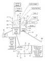
- FIG. 1is a diagrammatic representation of a system for remote endoscope handle manipulation according to some embodiments of the disclosed subject matter, the system being removed from an endoscope handle.
- FIG. 2is a is a diagrammatic representation of a system for remote endoscope handle manipulation according to some embodiments of the disclosed subject matter, the system being attached to an endoscope handle.
- FIG. 3is a is a diagrammatic representation of a system for remote endoscope handle manipulation according to some embodiments of the disclosed subject matter, the system being attached to an endoscope handle.
- FIG. 4is a perspective view of a system for remote endoscope handle manipulation according to some embodiments of the disclosed subject matter, the system being attached to an endoscope handle.
- FIG. 5is an elevational view of an interior portion of a system for remote endoscope handle manipulation according to some embodiments of the disclosed subject matter.
- the present inventorshave recognized, among other things, that current endoscopic technology involves the presence of two to three doctors (surgeons/endoscopists) to perform a procedure.
- Robotic endoscopic surgery systemsare not yet commercially available, and, if or when such systems become available, the costs of such systems may inhibit wide usage of the systems.
- the present inventorshave developed systems and methods for remote or robotic endoscope handle manipulation, which, among other things, can reduce the number of doctors involved in an endoscopic procedure to one or two doctors. Moreover, the systems and methods can make use of existing endoscope devices, thereby reducing additional costs associated with the use of the present systems and methods. Additionally, the present systems and methods can be put into practice currently and can be made commercially available in the short term.
- a system for remote endoscope handle manipulationincludes a portion that fits over at least a portion of a handle of an existing endoscope and is configured to manipulate one or more controls on the endoscope handle.
- the systemincludes a controller for a doctor or other operator to use to remotely manipulate the one or more controls on the endoscope handle.
- the controllerincludes a foot pedal to allow the operator to remotely control at least some aspects of the endoscope with a foot, thereby freeing up a hand of the operator, such as to facilitate performing one or more other aspects of the endoscopic procedure.
- an endoscope 60includes a shaft 64 and a handle 62 with one or more control devices 70 associated with the handle 62 .
- the control devices 70include two gears, such as a first or outer gear 70 A and a second or inner gear 70 B, that respectively control upward/downward movement and side-to-side movement of a tip 64 A of the endoscope shaft 64 .
- the control devices 70can further include a first button 70 C for controlling suction/insufflation and a second button 70 D for controlling irrigation. As shown in FIG.
- the endoscope 60can further include a third button 70 E, which can be used to control another operational aspect of the endoscope 60 , such as, for instance, power, camera, light, suction or insufflation (e.g., if suction and insufflation are not controlled with the same control device), or another endoscopic function.
- a third button 70 Ecan be used to control another operational aspect of the endoscope 60 , such as, for instance, power, camera, light, suction or insufflation (e.g., if suction and insufflation are not controlled with the same control device), or another endoscopic function.
- natural orifice transluminal endoscopic surgeriescan be performed by introducing the shaft 64 into a patient's orifice (for instance, the mouth, anus, vagina, or another orifice, or the umbilicus or another incision) and directing the shaft 64 to a desired location within the patient's body, such as by external urging or torquing ( FIGS. 2 and 3 depict a possible location along the shaft 64 for such urging or torquing) of the shaft 64 and controlling movements of the tip 64 A with the first and second gears 70 A, 70 B.
- a patient's orificefor instance, the mouth, anus, vagina, or another orifice, or the umbilicus or another incision
- FIGS. 2 and 3depict a possible location along the shaft 64 for such urging or torquing
- the endoscope 60includes a port 64 C for the introduction of one or more endoscopic devices or tools 80 , such as, for instance graspers, endoscopic shears, electrocautery devices, cameras, lights, or other devices or tools.
- the port 64 Ccan include first and second channels 64 C, 64 D so that two tools or devices 80 can be inserted into the shaft 64 at the same time.
- the port 64 Ccan include more than or fewer than two channels.
- the systems 10attach to an existing flexible endoscope 60 to allow for the first and second gears 70 A, 70 B of the endoscope 60 to be controlled remotely with a controller 20 .
- the controller 20includes a foot pedal interface 20 . This can liberate the activity of one operator hand and enable two and possibly even one operator to perform NOTES surgery.
- the controller 20includes one or more controls 22 such as buttons, pedals, or switches, for instance, which allow the operator to actuate one or more of the controls 22 , for instance, with a foot, to control aspects of the endoscope 60 .
- the controls 22can include four arrow buttons, which can control movement of the tip 64 A of the endoscope shaft 64 .
- Other controlscan be included on the controller 20 , such as to control one or more other aspects of the endoscope 60 , such as suction, insufflation, irrigation, or operation of one or more endoscopic tools or devices used with the endoscope 60 .
- the system 10includes or is coupled to an electrical or other power source 30 to power one or more components of the system 10 .
- the power source 30can include a plug or other connector for attaching to an external source of power, such as a wall outlet or a generator, or can include one or more batteries.
- the systems 10can include a cradle or holder 40 ( FIG. 2 ) for holding or otherwise restraining movement of the endoscope handle 62 .
- the handle 62 or other portion of the endoscope 60 or system 10can be affixed or otherwise attached to or rested upon a portion of the holder 40 .
- Another portion of the holder 40can then be affixed or otherwise attached to or placed on a table, stand, or other surface.
- the holder 40can include legs or a base for placement on a table, or the holder can include a clamp for fixed attachment to a table.
- the holder 40can be used to hold the endoscope 60 or system 10 during use, for instance, at a particular orientation, so that an operator need not hold the endoscope 60 or system 10 .
- Use of the holder 40helps further liberate one or more hands of one or more operators, such as to allow an operator to perform one or more other activities.
- the systems 10can be configured to fit one or most standard flexible endoscope handles.
- endoscopesare made by two companies, Olympus and Storz, with both companies making endoscopes with inner and outer overlapping gear controls and separate buttons for suction and irrigation control, such as shown in FIGS. 1 and 4 .
- the system 10includes a housing 12 that is sized and shaped to fit over at least a portion of the endoscope handle 62 .
- FIG. 4shows an example in which the housing 12 (shown in phantom) is placed over a portion of the handle 62 to control of or otherwise interact with the control devices 70 A, 70 B, 70 C, 70 D, 70 E of the endoscope 60 .
- the housing 12can be attached to the endoscope handle 62 , for instance, by forming a shell around all or a portion of the handle 62 ; using one or more straps, clamps, or other attachment devices; using a detent configuration to snap onto the handle 62 ; or using frictional engagement between the handle 62 and the housing 12 .
- the housingcan be a frame or any other structure, including one or more straps, tape, or adhesive, for instance, that can be attached to the handle 62 or other portion of the endoscope 60 to position one or more manipulators, as described below, to allow control of or interaction with the control devices of the endoscope 60 .
- the housing 12includes one or more manipulators 14 , which are positioned such that they will align with a respective one or more of the control devices 70 of the endoscope 60 when the housing 12 is attached to the handle 62 .
- a first gear manipulator 14 Acan be configured to be complementarily shaped and sized to engage with the first gear 70 A of the endoscope handle 62 , such that rotation of the first gear manipulator 14 A causes rotation of the first gear 70 A of the endoscope handle 62 .
- a second gear manipulator 14 Bcan be complementarily shaped and sized to engage with the second gear 70 B of the endoscope handle 62 , such that rotation of the second gear manipulator 14 B causes rotation of the second gear 70 B of the endoscope handle 62 .
- the first and second gear manipulators 14 A, 14 Bare drivingly coupled to first and second actuators 16 A, 16 B, respectively.
- an outer edge of each of the first and second gear manipulators 14 A, 14 Bcan include gear teeth, which can be engaged by a worm or pinion driven by one of the first and second actuators 16 A, 16 B.
- the first or second actuators 16 A, 16 Bcan include a rotational actuator, such as a stepper motor, for instance.
- the first or second actuators 16 A, 16 Bcan be independently controlled, such as by actuating different controls 22 on the controller 20 , thereby allowing the operator to individually control different aspects of the endoscope 60 using the controller 20 .
- the systems 10can include one or more translational manipulators, which align with translational control devices, such as buttons, sliders, or switches, of the endoscope handle 62 , with the housing 12 attached to the endoscope handle 62 .
- the housingincludes first, second, and third button manipulators 14 C, 14 D, 14 E, which are configured to align with the first, second, and third buttons 70 C, 70 D, 70 E, such that translation of the first, second, or third button manipulator 14 C, 14 D, 14 E causes translation of the first, second, or third button 70 C, 70 D, 70 E of the endoscope handle 62 .
- each of the first, second, and third button manipulators 14 C, 14 D, 14 Eprovides a surface coupled to a driven portion of a translational actuator, such as a solenoid, for instance.
- the first button manipulator 14 Cis coupled to a third actuator 16 C
- the second button manipulator 14 Dis coupled to a fourth actuator 16 D
- the third button manipulator 14 Eis coupled to a fifth actuator 16 E.
- the third, fourth, and fifth actuators 16 C, 16 D, 16 Ecan be independently controlled such as by respective actuating controls 24 ( FIG. 1 ) on the controller 20 . This allows the operator to remotely control one or more aspects of the endoscope 60 using the controller 20 , without requiring the operator to manipulate controls at the endoscope handle.
- the number of manipulators and actuatorscan be increased or decreased, such as to correspond to the number of translational controls on the endoscope.
- the housingneed not include any translational actuators if manual actuation of the translational controls of the endoscope is desired.
- the housingcan include an opening therein to allow operator access to one or more of the buttons 70 C, 70 D, 70 E, or can include one or more manipulators that, rather than being coupled to respective actuators, are instead manually operated by the operator from outside of the housing 12 .
- controller 20is described above as electrically communicating with actuators to manipulate the control devices 70 of the endoscope 60
- the controllercan mechanically communicate with the manipulators, such as by using rotating shafts or translating wires or shafts to mechanically deliver drive power from the controller to the manipulators.
- the shafts or wirescan be rotated or translated using actuators, such as stepper motors or solenoids, for instance, associated with the controller.
- the system 10 and endoscope handle 62can be placed in the cradle or holder 40 and the endoscope tip 64 A can be robotically-controlled via one or more commands from the controller 20 , such as the foot pedal 20 .
- the holder or a holding portionis integrated with the control housing or the endoscope (for instance, the endoscope handle), rather than being a separate component. This allows one operator to torque the endoscope shaft 64 , as desired, with one hand and to control the one or more endoscopic instruments 80 that are passed through one or more of the channels 64 C, 64 D with the other hand, thus, permitting a single operator to perform a NOTES procedure or SPA surgery.
- the present inventorsbelieve that such a system can be cheaper than a fully robotic NOTES endoscope because hospitals can use existing endoscopes with the present systems and methods instead of having to invest in new robotic NOTES endoscopes should they become available on the market.
- the systemscan include one or more attachments that can control one or more of the endoscopic instruments 80 passed through one or more of the channels 64 C, 64 D.
- the systemincludes a device to remotely control the torquing of the endoscopic shaft 64 .
- one or more actuatorscan be attached to the endoscopic shaft 64 to urge the shaft in one or more directions, including an axial direction, a rotational direction, and a radial direction.
- an existing endoscopecan be totally remotely or robotically controlled.
- methods of using the remote endoscope handle manipulation system 10include attaching the control housing 12 to the handle 12 of the endoscope 60 , such that at least one manipulator 14 A, 14 B, 14 C, 14 D, or 14 E of the control housing 12 engages a corresponding control device 70 A, 70 B, 70 C, 70 D, or 70 E of the endoscope handle 62 .
- the operatorcan remotely control at least one manipulator 14 A, 14 B, 14 C, 14 D, or 14 E to remotely operate at least one control device 70 A, 70 B, 70 C, 70 D, or 70 E of the endoscope handle 62 .
- the operatoruses a controller 20 to operate at least one control device 70 A, 70 B, 70 C, 70 D, or 70 E of the endoscope handle 62 .
- the controller 20includes a foot pedal 20 to allow the operator to operate one or more aspects of the endoscope 60 by foot, thereby freeing up use of an arm or hand of the operator.
- the operatorcan restrain at least a portion of the system 10 , such as to inhibit movement of the endoscope handle 62 .
- the system 10can be restrained using the holder 40 , such as described above. In this way, the operator can free-up use of a hand to allow the operator to control one or more additional endoscope operations, thereby potentially decreasing the number of operators required to perform a NOTES or other endoscopic procedure.
- the terms “a” or “an”are used, as is common in patent documents, to include one or more than one, independent of any other instances or usages of “at least one” or “one or more.”
- the term “or”is used to refer to a nonexclusive or, such that “A or B” includes “A but not B,” “B but not A,” and “A and B,” unless otherwise indicated.
Landscapes
- Life Sciences & Earth Sciences (AREA)
- Health & Medical Sciences (AREA)
- Surgery (AREA)
- Engineering & Computer Science (AREA)
- Biophysics (AREA)
- Medical Informatics (AREA)
- Nuclear Medicine, Radiotherapy & Molecular Imaging (AREA)
- Optics & Photonics (AREA)
- Pathology (AREA)
- Radiology & Medical Imaging (AREA)
- Veterinary Medicine (AREA)
- Biomedical Technology (AREA)
- Heart & Thoracic Surgery (AREA)
- Physics & Mathematics (AREA)
- Molecular Biology (AREA)
- Animal Behavior & Ethology (AREA)
- General Health & Medical Sciences (AREA)
- Public Health (AREA)
- Mechanical Engineering (AREA)
- Signal Processing (AREA)
- Endoscopes (AREA)
- Instruments For Viewing The Inside Of Hollow Bodies (AREA)
Abstract
Description
Claims (16)
Priority Applications (1)
| Application Number | Priority Date | Filing Date | Title |
|---|---|---|---|
| US12/866,473US8409080B2 (en) | 2008-02-07 | 2009-02-06 | Remote endoscope handle manipulation |
Applications Claiming Priority (3)
| Application Number | Priority Date | Filing Date | Title |
|---|---|---|---|
| US2681908P | 2008-02-07 | 2008-02-07 | |
| PCT/US2009/000749WO2009099633A1 (en) | 2008-02-07 | 2009-02-06 | Remote endoscope handle manipulation |
| US12/866,473US8409080B2 (en) | 2008-02-07 | 2009-02-06 | Remote endoscope handle manipulation |
Related Parent Applications (1)
| Application Number | Title | Priority Date | Filing Date |
|---|---|---|---|
| US61026819Division | 2008-02-07 |
Publications (2)
| Publication Number | Publication Date |
|---|---|
| US20110201886A1 US20110201886A1 (en) | 2011-08-18 |
| US8409080B2true US8409080B2 (en) | 2013-04-02 |
Family
ID=40952397
Family Applications (1)
| Application Number | Title | Priority Date | Filing Date |
|---|---|---|---|
| US12/866,473Active2028-10-01US8409080B2 (en) | 2008-02-07 | 2009-02-06 | Remote endoscope handle manipulation |
Country Status (4)
| Country | Link |
|---|---|
| US (1) | US8409080B2 (en) |
| EP (1) | EP2247229B1 (en) |
| JP (1) | JP2011510789A (en) |
| WO (1) | WO2009099633A1 (en) |
Cited By (9)
| Publication number | Priority date | Publication date | Assignee | Title |
|---|---|---|---|---|
| US20120065470A1 (en)* | 2010-09-14 | 2012-03-15 | The Johns Hopkins University | Robotic system to augment endoscopes |
| US20120277534A1 (en)* | 2010-10-08 | 2012-11-01 | Olympus Medical Systems Corp. | Endoscope |
| US20140296633A1 (en)* | 2008-02-07 | 2014-10-02 | The Trustees Of Columbia University In The City Of New York | Remote endoscope handle manipulation |
| WO2017205548A1 (en)* | 2016-05-24 | 2017-11-30 | Phoenix Spine Surgery Center, Ltd. | Methods and apparatus for facilitating direct visualized rhizotomy |
| US20180098687A1 (en)* | 2015-08-11 | 2018-04-12 | Human Xtensions Ltd. | Control unit for a flexible endoscope |
| US10376382B2 (en) | 2016-11-16 | 2019-08-13 | Phoenix Spine Holdings, Inc. | Methods and apparatus for facilitating a posterior lumbar interbody fusion procedure |
| US11076902B2 (en) | 2018-02-22 | 2021-08-03 | Phoenix Spine Holdings, Inc. | Locking screw assembly for facilitating direct lateral interbody fusion procedures |
| WO2022072327A1 (en)* | 2020-09-29 | 2022-04-07 | Boston Scientific Scimed, Inc. | Medical device controller |
| US11529038B2 (en)* | 2018-10-02 | 2022-12-20 | Elements Endoscopy, Inc. | Endoscope with inertial measurement units and / or haptic input controls |
Families Citing this family (4)
| Publication number | Priority date | Publication date | Assignee | Title |
|---|---|---|---|---|
| US9498112B1 (en) | 2013-03-15 | 2016-11-22 | Brent Stewart | Laryngoscope |
| US11730349B2 (en)* | 2019-10-25 | 2023-08-22 | Canon U.S.A., Inc. | Steerable medical device with bending sections and improved connector therefor |
| WO2022015923A1 (en)* | 2020-07-17 | 2022-01-20 | Smith & Nephew, Inc. | Touchless control of surgical devices |
| US20240349999A1 (en)* | 2023-04-18 | 2024-10-24 | Gregory Brian BOWLES | Remotely operated hand-held bronchoscope |
Citations (40)
| Publication number | Priority date | Publication date | Assignee | Title |
|---|---|---|---|---|
| US4593679A (en)* | 1984-02-09 | 1986-06-10 | Warner-Lambert Technologies, Inc. | Connector device for an endoscope |
| US4919112A (en)* | 1989-04-07 | 1990-04-24 | Schott Fiber Optics | Low-cost semi-disposable endoscope |
| US4941454A (en) | 1989-10-05 | 1990-07-17 | Welch Allyn, Inc. | Servo actuated steering mechanism for borescope or endoscope |
| US5347989A (en)* | 1992-09-11 | 1994-09-20 | Welch Allyn, Inc. | Control mechanism for steerable elongated probe having a sealed joystick |
| JPH07275222A (en) | 1994-04-15 | 1995-10-24 | Olympus Optical Co Ltd | Mr probe holding device in celom |
| US5524180A (en)* | 1992-08-10 | 1996-06-04 | Computer Motion, Inc. | Automated endoscope system for optimal positioning |
| US5634466A (en)* | 1993-11-19 | 1997-06-03 | Advanced Technology Laboratories, Inc. | Ultrasonic transesophageal probe with detachable transducer tip |
| US5951461A (en)* | 1996-12-20 | 1999-09-14 | Nyo; Tin | Image-guided laryngoscope for tracheal intubation |
| US6004263A (en)* | 1996-03-13 | 1999-12-21 | Hihon Kohden Corporation | Endoscope with detachable operation unit and insertion unit |
| US6059719A (en)* | 1997-08-06 | 2000-05-09 | Olympus Optical Co., Ltd. | Endoscope system |
| US20010047183A1 (en) | 2000-04-05 | 2001-11-29 | Salvatore Privitera | Surgical device for the collection of soft tissue |
| US6371907B1 (en)* | 1996-11-18 | 2002-04-16 | Olympus Optical Co., Ltd. | Endoscope apparatus driving manipulation wires with drive motor in drum portion |
| US20020103418A1 (en) | 2001-01-30 | 2002-08-01 | Olympus Optical Co., Ltd. | Endoscope device |
| US6468265B1 (en)* | 1998-11-20 | 2002-10-22 | Intuitive Surgical, Inc. | Performing cardiac surgery without cardioplegia |
| US6569084B1 (en)* | 1999-03-31 | 2003-05-27 | Olympus Optical Co., Ltd. | Endoscope holder and endoscope device |
| US20030158462A1 (en) | 2001-12-10 | 2003-08-21 | Seisuke Takase | Endoscope device |
| US20030187328A1 (en) | 2002-03-29 | 2003-10-02 | Fuji Photo Optical Co., Ltd. | Endoscopic manual control knob, and a method for manufacturing same |
| US20030216617A1 (en)* | 1998-09-28 | 2003-11-20 | Kabushiki Kaisha Toshiba | Endoscope apparatus |
| US20040073083A1 (en)* | 2002-09-30 | 2004-04-15 | Olympus Optical Co., Ltd. | Electric bending endoscope |
| US6858005B2 (en)* | 2000-04-03 | 2005-02-22 | Neo Guide Systems, Inc. | Tendon-driven endoscope and methods of insertion |
| US20050054899A1 (en)* | 2003-05-13 | 2005-03-10 | Olympus Corporation | Endoscope apparatus |
| US20050059960A1 (en) | 2003-05-21 | 2005-03-17 | Johns Hopkins University | Devices, systems and methods for minimally invasive surgery of the throat and other portions of mammalian body |
| US20050267327A1 (en)* | 2004-02-26 | 2005-12-01 | Shuhei Iizuka | Endoscope |
| US7008376B2 (en)* | 2002-09-30 | 2006-03-07 | Olympus Corporation | Electric bending endoscope |
| US20060052664A1 (en)* | 2000-04-03 | 2006-03-09 | Julian Christopher A | Connector device for a controllable instrument |
| US20060161043A1 (en) | 2005-01-18 | 2006-07-20 | Martin Neumann | Drive for an endoscope |
| US20060258955A1 (en) | 2005-05-13 | 2006-11-16 | Hoffman David W | Endoscopic apparatus with integrated multiple biopsy device |
| US20070167674A1 (en) | 2006-01-13 | 2007-07-19 | Ryuichi Toyama | Endoscope, endoscope system, and method of manufacturing endoscope |
| EP1825801A1 (en) | 2004-12-03 | 2007-08-29 | Olympus Corporation | Bendable endoscope of type where insertion section is removable and electrically bendable endoscope device of type where insertion section is removable |
| US20070238927A1 (en)* | 2004-12-03 | 2007-10-11 | Olympus Corporation | Power driven bending endoscope with detachable insertion portion |
| US20080103358A1 (en)* | 2004-03-23 | 2008-05-01 | Keita Suzuki | Endoscope system |
| US20080119695A1 (en)* | 2005-07-14 | 2008-05-22 | Olympus Medical Systems Corp., | Endoscope |
| US20080214896A1 (en)* | 2007-01-10 | 2008-09-04 | Krupa Robert J | Endoscope with detachable elongation portion |
| US7435216B2 (en)* | 2004-04-22 | 2008-10-14 | Korea Advanced Institute Of Science And Technology | Robotized laparoscopic system |
| US20090012365A1 (en)* | 2005-07-22 | 2009-01-08 | Olympus Medical Systems Corp. | Endoscope |
| US7578786B2 (en)* | 2003-04-01 | 2009-08-25 | Boston Scientific Scimed, Inc. | Video endoscope |
| US7780593B2 (en)* | 2005-06-24 | 2010-08-24 | Olympus Medical Systems Corp. | Endoscope |
| US7850642B2 (en)* | 2004-03-05 | 2010-12-14 | Hansen Medical, Inc. | Methods using a robotic catheter system |
| US7918861B2 (en)* | 1998-02-24 | 2011-04-05 | Hansen Medical, Inc. | Flexible instrument |
| US8118732B2 (en)* | 2003-04-01 | 2012-02-21 | Boston Scientific Scimed, Inc. | Force feedback control system for video endoscope |
- 2009
- 2009-02-06EPEP09707539.4Apatent/EP2247229B1/ennot_activeNot-in-force
- 2009-02-06WOPCT/US2009/000749patent/WO2009099633A1/enactiveApplication Filing
- 2009-02-06JPJP2010545877Apatent/JP2011510789A/ennot_activeWithdrawn
- 2009-02-06USUS12/866,473patent/US8409080B2/enactiveActive
Patent Citations (43)
| Publication number | Priority date | Publication date | Assignee | Title |
|---|---|---|---|---|
| US4593679A (en)* | 1984-02-09 | 1986-06-10 | Warner-Lambert Technologies, Inc. | Connector device for an endoscope |
| US4919112A (en)* | 1989-04-07 | 1990-04-24 | Schott Fiber Optics | Low-cost semi-disposable endoscope |
| US4919112B1 (en)* | 1989-04-07 | 1993-12-28 | Low-cost semi-disposable endoscope | |
| US4941454A (en) | 1989-10-05 | 1990-07-17 | Welch Allyn, Inc. | Servo actuated steering mechanism for borescope or endoscope |
| US5524180A (en)* | 1992-08-10 | 1996-06-04 | Computer Motion, Inc. | Automated endoscope system for optimal positioning |
| US5347989A (en)* | 1992-09-11 | 1994-09-20 | Welch Allyn, Inc. | Control mechanism for steerable elongated probe having a sealed joystick |
| US5634466A (en)* | 1993-11-19 | 1997-06-03 | Advanced Technology Laboratories, Inc. | Ultrasonic transesophageal probe with detachable transducer tip |
| JPH07275222A (en) | 1994-04-15 | 1995-10-24 | Olympus Optical Co Ltd | Mr probe holding device in celom |
| US6004263A (en)* | 1996-03-13 | 1999-12-21 | Hihon Kohden Corporation | Endoscope with detachable operation unit and insertion unit |
| US6371907B1 (en)* | 1996-11-18 | 2002-04-16 | Olympus Optical Co., Ltd. | Endoscope apparatus driving manipulation wires with drive motor in drum portion |
| US5951461A (en)* | 1996-12-20 | 1999-09-14 | Nyo; Tin | Image-guided laryngoscope for tracheal intubation |
| US6059719A (en)* | 1997-08-06 | 2000-05-09 | Olympus Optical Co., Ltd. | Endoscope system |
| US7918861B2 (en)* | 1998-02-24 | 2011-04-05 | Hansen Medical, Inc. | Flexible instrument |
| US20030216617A1 (en)* | 1998-09-28 | 2003-11-20 | Kabushiki Kaisha Toshiba | Endoscope apparatus |
| US6468265B1 (en)* | 1998-11-20 | 2002-10-22 | Intuitive Surgical, Inc. | Performing cardiac surgery without cardioplegia |
| US6569084B1 (en)* | 1999-03-31 | 2003-05-27 | Olympus Optical Co., Ltd. | Endoscope holder and endoscope device |
| US6858005B2 (en)* | 2000-04-03 | 2005-02-22 | Neo Guide Systems, Inc. | Tendon-driven endoscope and methods of insertion |
| US20060052664A1 (en)* | 2000-04-03 | 2006-03-09 | Julian Christopher A | Connector device for a controllable instrument |
| US20010047183A1 (en) | 2000-04-05 | 2001-11-29 | Salvatore Privitera | Surgical device for the collection of soft tissue |
| US20020103418A1 (en) | 2001-01-30 | 2002-08-01 | Olympus Optical Co., Ltd. | Endoscope device |
| US20030158462A1 (en) | 2001-12-10 | 2003-08-21 | Seisuke Takase | Endoscope device |
| US20030187328A1 (en) | 2002-03-29 | 2003-10-02 | Fuji Photo Optical Co., Ltd. | Endoscopic manual control knob, and a method for manufacturing same |
| US7008376B2 (en)* | 2002-09-30 | 2006-03-07 | Olympus Corporation | Electric bending endoscope |
| US20040073083A1 (en)* | 2002-09-30 | 2004-04-15 | Olympus Optical Co., Ltd. | Electric bending endoscope |
| US8118732B2 (en)* | 2003-04-01 | 2012-02-21 | Boston Scientific Scimed, Inc. | Force feedback control system for video endoscope |
| US7578786B2 (en)* | 2003-04-01 | 2009-08-25 | Boston Scientific Scimed, Inc. | Video endoscope |
| US20050054899A1 (en)* | 2003-05-13 | 2005-03-10 | Olympus Corporation | Endoscope apparatus |
| US20050059960A1 (en) | 2003-05-21 | 2005-03-17 | Johns Hopkins University | Devices, systems and methods for minimally invasive surgery of the throat and other portions of mammalian body |
| US20050267327A1 (en)* | 2004-02-26 | 2005-12-01 | Shuhei Iizuka | Endoscope |
| US7850642B2 (en)* | 2004-03-05 | 2010-12-14 | Hansen Medical, Inc. | Methods using a robotic catheter system |
| US20080103358A1 (en)* | 2004-03-23 | 2008-05-01 | Keita Suzuki | Endoscope system |
| US7435216B2 (en)* | 2004-04-22 | 2008-10-14 | Korea Advanced Institute Of Science And Technology | Robotized laparoscopic system |
| US20070238927A1 (en)* | 2004-12-03 | 2007-10-11 | Olympus Corporation | Power driven bending endoscope with detachable insertion portion |
| US20070232856A1 (en)* | 2004-12-03 | 2007-10-04 | Olympus Corporation | Bending endoscope with detachable insertion portion and power driven bending endoscope device with detachable insertion portion |
| EP1825801A1 (en) | 2004-12-03 | 2007-08-29 | Olympus Corporation | Bendable endoscope of type where insertion section is removable and electrically bendable endoscope device of type where insertion section is removable |
| US7828723B2 (en)* | 2004-12-03 | 2010-11-09 | Olympus Corporation | Power driven bending endoscope with detachable insertion portion |
| US20060161043A1 (en) | 2005-01-18 | 2006-07-20 | Martin Neumann | Drive for an endoscope |
| US20060258955A1 (en) | 2005-05-13 | 2006-11-16 | Hoffman David W | Endoscopic apparatus with integrated multiple biopsy device |
| US7780593B2 (en)* | 2005-06-24 | 2010-08-24 | Olympus Medical Systems Corp. | Endoscope |
| US20080119695A1 (en)* | 2005-07-14 | 2008-05-22 | Olympus Medical Systems Corp., | Endoscope |
| US20090012365A1 (en)* | 2005-07-22 | 2009-01-08 | Olympus Medical Systems Corp. | Endoscope |
| US20070167674A1 (en) | 2006-01-13 | 2007-07-19 | Ryuichi Toyama | Endoscope, endoscope system, and method of manufacturing endoscope |
| US20080214896A1 (en)* | 2007-01-10 | 2008-09-04 | Krupa Robert J | Endoscope with detachable elongation portion |
Non-Patent Citations (1)
| Title |
|---|
| European Search Report dated Jul. 30, 2012, from Counterpart Application No. EP 09 70 7539 (4 pages). |
Cited By (15)
| Publication number | Priority date | Publication date | Assignee | Title |
|---|---|---|---|---|
| US20140296633A1 (en)* | 2008-02-07 | 2014-10-02 | The Trustees Of Columbia University In The City Of New York | Remote endoscope handle manipulation |
| US9706907B2 (en)* | 2008-02-07 | 2017-07-18 | Institute For Cancer Research | Remote endoscope handle manipulation |
| US20120065470A1 (en)* | 2010-09-14 | 2012-03-15 | The Johns Hopkins University | Robotic system to augment endoscopes |
| US20120277534A1 (en)* | 2010-10-08 | 2012-11-01 | Olympus Medical Systems Corp. | Endoscope |
| US8758233B2 (en)* | 2010-10-08 | 2014-06-24 | Olympus Medical Systems Corp. | Endoscope |
| US20180098687A1 (en)* | 2015-08-11 | 2018-04-12 | Human Xtensions Ltd. | Control unit for a flexible endoscope |
| US10835108B2 (en)* | 2015-08-11 | 2020-11-17 | Human Xtensions Ltd. | Control unit for a flexible endoscope |
| WO2017205548A1 (en)* | 2016-05-24 | 2017-11-30 | Phoenix Spine Surgery Center, Ltd. | Methods and apparatus for facilitating direct visualized rhizotomy |
| US10201267B2 (en) | 2016-05-24 | 2019-02-12 | Phoenix Spine Holdings, Inc. | Methods and apparatus for facilitating direct visualized rhizotomy |
| US10376382B2 (en) | 2016-11-16 | 2019-08-13 | Phoenix Spine Holdings, Inc. | Methods and apparatus for facilitating a posterior lumbar interbody fusion procedure |
| US11076902B2 (en) | 2018-02-22 | 2021-08-03 | Phoenix Spine Holdings, Inc. | Locking screw assembly for facilitating direct lateral interbody fusion procedures |
| US11529038B2 (en)* | 2018-10-02 | 2022-12-20 | Elements Endoscopy, Inc. | Endoscope with inertial measurement units and / or haptic input controls |
| US12185908B2 (en) | 2018-10-02 | 2025-01-07 | Elements Endoscopy Inc. | Endoscope with inertial measurement units and/or haptic input controls |
| WO2022072327A1 (en)* | 2020-09-29 | 2022-04-07 | Boston Scientific Scimed, Inc. | Medical device controller |
| US12178404B2 (en) | 2020-09-29 | 2024-12-31 | Boston Scientific Scimed, Inc. | Medical device controller |
Also Published As
| Publication number | Publication date |
|---|---|
| JP2011510789A (en) | 2011-04-07 |
| US20110201886A1 (en) | 2011-08-18 |
| EP2247229A4 (en) | 2012-09-05 |
| EP2247229A1 (en) | 2010-11-10 |
| EP2247229B1 (en) | 2016-02-03 |
| WO2009099633A1 (en) | 2009-08-13 |
Similar Documents
| Publication | Publication Date | Title |
|---|---|---|
| US8409080B2 (en) | Remote endoscope handle manipulation | |
| US9706907B2 (en) | Remote endoscope handle manipulation | |
| US20240366262A1 (en) | Apparatus and methods for hybrid endoscopic and laparoscopic surgery | |
| US12076038B2 (en) | Rotary input for lever actuation | |
| CN101340848B (en) | Sterile surgical adaptor | |
| US10085806B2 (en) | Minimally invasive instrument for robotic surgery | |
| KR101800723B1 (en) | Motor interface for parallel drive shafts within an independently rotating member | |
| CN101242788B (en) | Surgical accessory clamp and system | |
| US7955322B2 (en) | Wireless communication in a robotic surgical system | |
| KR20190086402A (en) | A sterile adapter assembly for a robotic surgical system | |
| KR20190086400A (en) | A locking mechanism to secure a sterile adapter assembly to an actuator assembly for a robotic surgical system | |
| EP3871629A1 (en) | Wearable surgical robot arm | |
| Zhang et al. | Cooperative robotic assistant for laparoscopic surgery: CoBRASurge | |
| EP4196041B1 (en) | A surgical camera | |
| CN113951948B (en) | Surgical instrument control unit |
Legal Events
| Date | Code | Title | Description |
|---|---|---|---|
| AS | Assignment | Owner name:THE TRUSTEES OF COLUMBIA UNIVERSITY IN THE CITY OF Free format text:ASSIGNMENT OF ASSIGNORS INTEREST;ASSIGNORS:GUMBS, ANDREW A.;MILONE, LUCA;SIGNING DATES FROM 20090808 TO 20090817;REEL/FRAME:024830/0027 | |
| AS | Assignment | Owner name:THE TRUSTEES OF COLUMBIA UNIVERSITY IN THE CITY OF Free format text:ASSIGNMENT OF ASSIGNORS INTEREST;ASSIGNORS:GUMBS, ANDREW A.;MILONE, LUCA;SIGNING DATES FROM 20100902 TO 20100910;REEL/FRAME:025240/0102 | |
| STCF | Information on status: patent grant | Free format text:PATENTED CASE | |
| FPAY | Fee payment | Year of fee payment:4 | |
| AS | Assignment | Owner name:THE TRUSTEES OF COLUMBIA UNIVERSITY IN THE CITY OF Free format text:ASSIGNMENT OF ASSIGNORS INTEREST;ASSIGNOR:THE TRUSTEES OF COLUMBIA UNIVERSITY IN THE CITY OF NEW YORK;REEL/FRAME:049277/0739 Effective date:20190516 Owner name:INSTITUTE FOR CANCER RESEARCH D/B/A THE RESEARCH I Free format text:ASSIGNMENT OF ASSIGNORS INTEREST;ASSIGNOR:THE TRUSTEES OF COLUMBIA UNIVERSITY IN THE CITY OF NEW YORK;REEL/FRAME:049277/0739 Effective date:20190516 | |
| MAFP | Maintenance fee payment | Free format text:PAYMENT OF MAINTENANCE FEE, 8TH YR, SMALL ENTITY (ORIGINAL EVENT CODE: M2552); ENTITY STATUS OF PATENT OWNER: SMALL ENTITY Year of fee payment:8 | |
| MAFP | Maintenance fee payment | Free format text:PAYMENT OF MAINTENANCE FEE, 12TH YR, SMALL ENTITY (ORIGINAL EVENT CODE: M2553); ENTITY STATUS OF PATENT OWNER: SMALL ENTITY Year of fee payment:12 |