US8408811B2 - Fusion-splice fiber optic connectors and related tools - Google Patents
Fusion-splice fiber optic connectors and related toolsDownload PDFInfo
- Publication number
- US8408811B2 US8408811B2US12/077,126US7712608AUS8408811B2US 8408811 B2US8408811 B2US 8408811B2US 7712608 AUS7712608 AUS 7712608AUS 8408811 B2US8408811 B2US 8408811B2
- Authority
- US
- United States
- Prior art keywords
- boot
- fusion
- splice
- connector assembly
- connector
- Prior art date
- Legal status (The legal status is an assumption and is not a legal conclusion. Google has not performed a legal analysis and makes no representation as to the accuracy of the status listed.)
- Expired - Fee Related, expires
Links
- 239000000835fiberSubstances0.000titleclaimsabstractdescription110
- 230000004927fusionEffects0.000claimsabstractdescription57
- 239000013307optical fiberSubstances0.000claimsabstractdescription50
- 238000007526fusion splicingMethods0.000claimsabstractdescription19
- 230000003287optical effectEffects0.000claimsabstractdescription4
- 230000006835compressionEffects0.000claimsdescription21
- 238000007906compressionMethods0.000claimsdescription21
- 230000002633protecting effectEffects0.000claimsdescription8
- 230000000295complement effectEffects0.000claimsdescription4
- 230000002401inhibitory effectEffects0.000claimsdescription2
- 239000000463materialSubstances0.000description15
- 230000001012protectorEffects0.000description10
- 239000000428dustSubstances0.000description8
- 230000014759maintenance of locationEffects0.000description6
- 239000000853adhesiveSubstances0.000description5
- 230000001070adhesive effectEffects0.000description5
- 238000009434installationMethods0.000description4
- 230000007246mechanismEffects0.000description4
- 230000009471actionEffects0.000description3
- 238000010276constructionMethods0.000description3
- -1polybutylene terephthalatePolymers0.000description3
- 229920001707polybutylene terephthalatePolymers0.000description3
- 239000004743PolypropyleneSubstances0.000description2
- 229920003182Surlyn®Polymers0.000description2
- 238000005452bendingMethods0.000description2
- 230000008901benefitEffects0.000description2
- 238000000576coating methodMethods0.000description2
- 239000006260foamSubstances0.000description2
- 238000007373indentationMethods0.000description2
- 230000003993interactionEffects0.000description2
- 239000000203mixtureSubstances0.000description2
- 238000012986modificationMethods0.000description2
- 230000004048modificationEffects0.000description2
- 229920001155polypropylenePolymers0.000description2
- 229920001296polysiloxanePolymers0.000description2
- 238000002360preparation methodMethods0.000description2
- 230000001681protective effectEffects0.000description2
- 229920006346thermoplastic polyester elastomerPolymers0.000description2
- SYJPAKDNFZLSMV-HYXAFXHYSA-N(Z)-2-methylpropanal oximeChemical groupCC(C)\C=N/OSYJPAKDNFZLSMV-HYXAFXHYSA-N0.000description1
- KJLPSBMDOIVXSN-UHFFFAOYSA-N4-[4-[2-[4-(3,4-dicarboxyphenoxy)phenyl]propan-2-yl]phenoxy]phthalic acidChemical compoundC=1C=C(OC=2C=C(C(C(O)=O)=CC=2)C(O)=O)C=CC=1C(C)(C)C(C=C1)=CC=C1OC1=CC=C(C(O)=O)C(C(O)=O)=C1KJLPSBMDOIVXSN-UHFFFAOYSA-N0.000description1
- OKTJSMMVPCPJKN-UHFFFAOYSA-NCarbonChemical compound[C]OKTJSMMVPCPJKN-UHFFFAOYSA-N0.000description1
- 239000004593EpoxySubstances0.000description1
- 239000004820Pressure-sensitive adhesiveSubstances0.000description1
- BLRPTPMANUNPDV-UHFFFAOYSA-NSilaneChemical compound[SiH4]BLRPTPMANUNPDV-UHFFFAOYSA-N0.000description1
- 239000002390adhesive tapeSubstances0.000description1
- 239000004760aramidSubstances0.000description1
- 229920003235aromatic polyamidePolymers0.000description1
- 230000005540biological transmissionEffects0.000description1
- 229910052799carbonInorganic materials0.000description1
- 239000011248coating agentSubstances0.000description1
- 230000000694effectsEffects0.000description1
- 238000010891electric arcMethods0.000description1
- 239000003292glueSubstances0.000description1
- 230000005484gravityEffects0.000description1
- 230000003116impacting effectEffects0.000description1
- 238000005304joiningMethods0.000description1
- 238000004519manufacturing processMethods0.000description1
- 230000013011matingEffects0.000description1
- 239000004033plasticSubstances0.000description1
- 229920003023plasticPolymers0.000description1
- 230000035939shockEffects0.000description1
- 229910000077silaneInorganic materials0.000description1
- 239000000758substrateSubstances0.000description1
- 238000003466weldingMethods0.000description1
Images


Classifications
- G—PHYSICS
- G02—OPTICS
- G02B—OPTICAL ELEMENTS, SYSTEMS OR APPARATUS
- G02B6/00—Light guides; Structural details of arrangements comprising light guides and other optical elements, e.g. couplings
- G02B6/24—Coupling light guides
- G02B6/36—Mechanical coupling means
- G02B6/38—Mechanical coupling means having fibre to fibre mating means
- G02B6/3807—Dismountable connectors, i.e. comprising plugs
- G02B6/3833—Details of mounting fibres in ferrules; Assembly methods; Manufacture
- G02B6/3846—Details of mounting fibres in ferrules; Assembly methods; Manufacture with fibre stubs
- G—PHYSICS
- G02—OPTICS
- G02B—OPTICAL ELEMENTS, SYSTEMS OR APPARATUS
- G02B6/00—Light guides; Structural details of arrangements comprising light guides and other optical elements, e.g. couplings
- G02B6/24—Coupling light guides
- G02B6/255—Splicing of light guides, e.g. by fusion or bonding
- G02B6/2551—Splicing of light guides, e.g. by fusion or bonding using thermal methods, e.g. fusion welding by arc discharge, laser beam, plasma torch
- G—PHYSICS
- G02—OPTICS
- G02B—OPTICAL ELEMENTS, SYSTEMS OR APPARATUS
- G02B6/00—Light guides; Structural details of arrangements comprising light guides and other optical elements, e.g. couplings
- G02B6/24—Coupling light guides
- G02B6/255—Splicing of light guides, e.g. by fusion or bonding
- G02B6/2558—Reinforcement of splice joint
- G—PHYSICS
- G02—OPTICS
- G02B—OPTICAL ELEMENTS, SYSTEMS OR APPARATUS
- G02B6/00—Light guides; Structural details of arrangements comprising light guides and other optical elements, e.g. couplings
- G02B6/24—Coupling light guides
- G02B6/36—Mechanical coupling means
- G02B6/38—Mechanical coupling means having fibre to fibre mating means
- G02B6/3807—Dismountable connectors, i.e. comprising plugs
- G02B6/3887—Anchoring optical cables to connector housings, e.g. strain relief features
- G02B6/38875—Protection from bending or twisting
- G—PHYSICS
- G02—OPTICS
- G02B—OPTICAL ELEMENTS, SYSTEMS OR APPARATUS
- G02B6/00—Light guides; Structural details of arrangements comprising light guides and other optical elements, e.g. couplings
- G02B6/24—Coupling light guides
- G02B6/36—Mechanical coupling means
- G02B6/38—Mechanical coupling means having fibre to fibre mating means
- G02B6/3807—Dismountable connectors, i.e. comprising plugs
- G02B6/3887—Anchoring optical cables to connector housings, e.g. strain relief features
- G02B6/3888—Protection from over-extension or over-compression
- G—PHYSICS
- G02—OPTICS
- G02B—OPTICAL ELEMENTS, SYSTEMS OR APPARATUS
- G02B6/00—Light guides; Structural details of arrangements comprising light guides and other optical elements, e.g. couplings
- G02B6/24—Coupling light guides
- G02B6/36—Mechanical coupling means
- G02B6/38—Mechanical coupling means having fibre to fibre mating means
- G02B6/3807—Dismountable connectors, i.e. comprising plugs
- G02B6/3887—Anchoring optical cables to connector housings, e.g. strain relief features
- G02B6/3889—Anchoring optical cables to connector housings, e.g. strain relief features using encapsulation for protection, e.g. adhesive, molding or casting resin
Definitions
- the present disclosurerelates to fiber optic connectors and related tools. More specifically, the present disclosure relates generally to fiber optic connectors having an optical fiber stub suitable for fusion-splicing for optical connection and related tools for the fiber optic connectors.
- fusion spliceris designed for a fusion-splice connector using a stub optical fiber in an extended length ferrule.
- the extended length ferrulehas a notch or hole cut near the middle where the fusion splice is made.
- the stub optical fiberends at the notch or hole and the field fiber is inserted into the opposite end of the ferrule for fusion splicing with the field fiber.
- the fusion spliceoccurs at the notch or hole near the middle of the ferrule.
- the bore of the ferruleserves as the alignment member for the fibers to be joined, which eliminates the need for aligning V-grooves in the splicer, and allows a very short overall length finished connector (i.e., a length similar to a conventional epoxy/polish connector).
- Another type of fusion-splice connectoruses a standard length ferrule with a short optical fiber stub that protrudes beyond the ferrule end. This type of fusion-splice connector has a special connector housing that surrounds the fusion splice for protecting the same.
- the overall length of this type of fusion-splice connectoris longer than other fusion-splice connectors, making it bulky and difficult to route or store by the craft.
- both fusion-splice connectors describedinclude multiple components that must be installed in the field to complete the connector.
- Fusion-splice connector designshave attempted to use a standard fusion splicer and eliminate the requirement of a dedicated fusion splicer, but have encountered difficulties meeting all of the requirements for the assembly.
- One such fusion-splice connecter design for use with a standard fusion splicerincludes an extended length body to house the fusion splice, which allows for a long length fiber stub that can be used with standard splicing machines.
- this fusion-splice connector designuses a long optical fiber stub for working with the V-grooves on a standard fusion-splicer chuck to align the fibers during fusion splicing.
- V-groovesrequire about 10 millimeters of bare optical fiber stub to extend from the ferrule or connector subassembly for fusion splicing.
- an extended length connector backshell or crimp bodyis attached for strain relieving the fiber optic cable.
- the added length of these fusion-splice connectorsmakes it difficult, if not impossible, to pass all of the Telcordia performance requirements. For instance, optical transmission under applied load is difficult to pass, due to the added moment arm of the longer connector body. Additionally, the extended length of this fusion-splice connector will not pass the Telcordia requirements for overall connector length.
- these fusion-spliced connectorsalso have a large number of parts that must be installed in the field by craft, thereby making installation cumbersome.
- the present disclosureprovides fiber optic connectors that are installed upon one or more optical fibers by fusion splicing using a standard fusion splicer.
- the connectoris constructed from a standard connector (SC-type in the accompanying figures, although LC or other types may be utilized) with an optical fiber stub such as a 900 micron tight buffered optical fiber or bare optical fiber extending from the rear. The end of the optical fiber is stripped and cleaved in preparation for fusion splicing. The optical fiber stub extending from the rear of the fiber optic connector is protected by a boot that is mechanically attached to the fiber optic connector.
- the bootis designed to flex without appreciable stretching/elongation under axial loads since it carries (i.e., transfers) forces from the strength members of the fiber optic cable to the fiber optic connector.
- the bootallows the strength member(s) of the fiber optic cable to be attached to the splice housing and support tensile load through the boot, instead of attaching the strength members directly to the fiber optic connector body.
- the end of the boothas a collar molded onto it for attaching it directly to the splice housing. Besides transferring loads therethrough, the splice housing also protects the fusion splice between the optical fiber stub and a field optical fiber.
- the cable end of the splice housingmay have barbs and/or a split collet for engaging and securing to the cable jacket.
- the strength members of the cablepass through a gap between the splice housings and are captured in the threads on the outside diameter by a nut that is screwed onto the splice housing. In other words, the nut compresses the collet/barbs into the cable jacket and secures (i.e., strain relieves) the strength members of the fiber optic cable.
- a fusion-splice fiber optic connectorincludes a connector subassembly comprising a connector housing, one or more ferrules and an optical fiber stub; a boot associated with the connector subassembly; a splice housing defining an internal clearance for maintaining the fusion splice between the optical fiber stub and a field optical fiber.
- the splice housingalso secures a portion of the boot and a portion of a cable using a securing component.
- the fiber optic connectorsare advantageous since the fiber optic connector may have a length that is similar to a conventional non-fusion spliced fiber optic connector because the fusion splice is moved to a location behind the flexible boot.
- the term “behind the boot”is defined herein as meaning that the fusion splice occurs both behind the fiber optic connector subassembly and the boot but still in close proximity to the fiber optic connector. Because the optical fiber stub extends beyond the boot when assembled, the fusion splice also extends beyond the boot.
- the fiber optic connectors disclosed hereinhave a small number of parts for the craft to handle, with only the housing nut required to be pre-installed on the fiber optic cable.
- a heat shrink tubingis provided pre-installed under the boot.
- the fiber optic connectors of the present inventionare also advantageous because they do not required a dedicated splicer; but, instead may be installed using a conventional alignment splicer such as V-groove alignment splicers or active alignment splicers.
- a cushionmay be included in the splice housing for securing and protecting the fusion splice from damage or rupture.
- the cushionmay be a tape product used in addition to or as an alternative to the heat shrink tubing noted above.
- the tape productbonds to itself to provide a protective wrap about the fusion splice.
- a glue lined heat shrinkmay be provided for cable jacket retention.
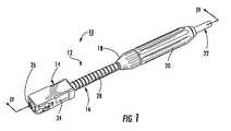
- FIG. 1is a perspective view of a fusion-spliced connector assembly according to one embodiment of the disclosure
- FIG. 2are perspective views of components of the fusion-spliced connector assembly as in FIG. 1 , particularly showing an exemplary assembly step of positioning the boot into the splice housing;
- FIG. 3is a perspective view of the splice housing of the fusion-spliced connector assembly as in FIG. 1 ;
- FIG. 4is a cross-section of the fusion-spliced connector assembly of FIG. 1 ;
- FIG. 5is a perspective view of another fusion-spliced connector assembly according to the disclosure.
- FIG. 6is a partially exploded view of the fusion-spliced connector assembly as in FIG. 5 ;
- FIG. 7is a perspective view of the boot used in the fusion-spliced connector assembly of FIGS. 5 and 6 ;
- FIG. 8is a perspective view of a disposable load adapter used to transport a connector assembly to a work station and to a fusion splicer to form the fusion-spliced connector assembly of FIG. 5 ;
- FIG. 9is a perspective view of the work station for transferring the connector assembly and a fiber optic cable to a fusion splicer to splice the same, thereby forming the fusion-spliced connector assembly as in FIG. 5 ;
- FIG. 10are perspective views of the work station, particularly showing steps for forming the fusion-spliced connector assembly as in FIG. 5 ;
- FIG. 11are perspective detailed views of the work station of FIG. 10 , particularly showing connections of the connector assembly and the fiber optic cable in the work station;
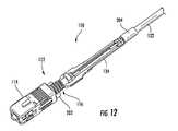
- FIG. 12is a perspective view of the fusion-spliced connector assembly of FIG. 5 shown in partial cross-section;
- FIG. 13is a rear end-view of the fusion-spliced connector assembly as in FIG. 12 ;
- FIG. 14is an exploded, perspective view of the exemplary splice housing of FIG. 5 showing the installation of a protective fiber cushion;
- FIG. 15is a plan view of a further embodiment of a fusion-spliced connector assembly according to the disclosure.
- FIG. 16is a perspective view of a load adaptor for use with a connector assembly in accordance with another embodiment of the disclosure.
- FIG. 17is a perspective view of another embodiment of a load adaptor similar to FIG. 16 according to a further embodiment of the disclosure.
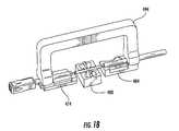
- FIG. 18is a perspective view of an attachable carrier arm for use with a load adaptor of FIG. 17 .
- the present disclosuregenerally provides various embodiments of a fiber optic connector assembly suitable for fusion splicing.
- the various embodimentsare made from lightweight, economical materials and components that are simple to manufacture and are easily used in the field by a technician.
- the fusion-spliced connector assembly 10has a connector subassembly 12 generally including a fiber optic connector 14 , which in this example is an SC-type connector, and a boot 16 .
- the connector subassembly 12is connected to a splice housing 18 by a securing component such as a compression nut 20 , thereby securing boot 16 to splice housing 18 and strength members (not visible) to splice housing 18 .
- a securing componentsuch as a compression nut 20
- FIG. 1shows that fiber optic connector 14 is a standard SC fiber optic connector that includes a housing 24 having a ferrule 26 therein.
- a SC fiber optic connectoris shown, the concepts of the present invention are applicable to other fiber optic connectors such as LC, ST, FC, multiple fiber connectors, or the like.
- Fiber optic connector 14is mechanically attached to boot 16 at a first end, and a second end extends toward splice housing 18 to protect a portion of an optical fiber such as a 900 micron tight buffer as discussed below. As shown in FIG.
- boot 16is tapered and defines one or more grooves 28 formed about an outer circumference of the boot 16 at the second end to allow the boot 16 to flex/bend without appreciable stretching such as up to 135 degrees or more. More particularly, the grooves 28 permit the boot 16 to flex/bend without buckling to meet the flex and 90° side pull requirements of Telcordia; however, boot 16 does not elongate substantially in length when subjected to axial loads. By way of example, a longitudinal extension of the boot 16 under a 15 pound axial load is about 2 millimeters or less. This is because unlike conventional connector boots, boot 16 of the invention is intended to transfer an axial load from the strength members of the fiber optic cable to fiber optic connector 14 .
- boot 16is attached to splice housing 18 and the strength members of fiber optic cable 22 are secured to splice housing 18 , instead of being strain relieved (i.e., crimped) directly to the fiber optic connector 14 like conventional fiber optic connectors.
- Boot 16 of this embodimentalso has an extended length.
- boot 16may have any suitable length.
- boots of the present inventionmay have a length between about 10 and 100 millimeters, and more preferably between about 10 and 60 millimeters. Longer boots allow the fiber optic connector to extend beyond a typical fusion splicer during fusion splicing and/or allows boot 16 to be bent up to 180 degrees ( FIG. 16 ) to inhibit interference issues during fusion splicing.
- Bootsmay have a relatively short length such as shown in FIG. 5 , which allows the fiber optic connector to fit within the fusion splicer to inhibit interference issues during fusion splicing.
- the boot constructionis selected to have a predetermined strength and/or geometry so that it can carry the transferred axial load without appreciable stretching.
- the boot 16is constructed of a semi-rigid material such as polybutylene terephthalate (PBT) having a wall thickness of about 0.8 millimeters, but other suitable wall thicknesses are possible.
- PBTpolybutylene terephthalate
- One suitable PBTis VALOX available from GE Plastics of Pittsfield, Mass.
- boot 16may be manufactured from other suitable materials such as HYTREL or SURLYN brand thermoplastic polyester elastomers (TPE) available from DUPONT, or the EXXTRAL brand material (a polypropylene blend) available from Exxon-Mobil.
- TPEthermoplastic polyester elastomers
- EXTRAL brand materiala polypropylene blend
- a portion of the splice housing 18 that will be discussed belowis abutted against the compression nut 20 .
- the splice housing 18 and the compression nut 20have knurled configurations or ridges to assist a technician in twisting or screwing the compression nut 20 and the splice housing 18 together.
- the rear end of connector assembly 12is shown with a pre-determined length of optical fiber stub 32 factory stripped and cleaved in preparation for fusion splicing.
- the optical fiber stub 32may be any suitable optical fiber capable of being bent sharply such as SMF28XB or CLEARCURVE optical fibers available from Corning, Incorporated.
- excess fiber length (EFL)is preloaded within boot 16 so that it can extend 2 millimeters or more before straining the optic fiber and impacting connector performance.
- the optical fiber stub 32may having a silane or carbon coating or treatment such as PROSAT or SATWIPES for increasing its durability.
- splice housing 18is configured for capturing and securing collar 30 of boot 16 therein to transfer forces through boot 16 to fiber optic connector 14 .
- splice housing 18is a two-piece clamshell housing having a first portion 34 and a second portion 36 in which collar 30 is seated.
- First portion 34 of splice housing 18includes a necked down portion behind the collar receiving portion for “grabbing”, for instance, the 900 micron tight buffer of the optical fiber stub 32 that is discussed in detail herein with respect to FIGS. 13 and 14 .
- first portion 34 of splice housing 18generally applies to second portion 36 described below with respect to FIG. 3 unless expressly stated otherwise. Additionally, although splice housing 18 is shown and described as two-pieces it could have other configurations such as a one-piece design with a living hinge between the portions or be formed from more than two-pieces.
- first portion 34 of splice housing 18includes a plurality of holes 38 into which rods, pins or other protrusions (not shown) of the second portion 36 may project for attaching the first and second portions 34 , 36 together by press or snap fit interaction and/or with adhesives.
- First portion 34also includes a groove 40 to accept the collar 30 of boot 16 to attach or anchor boot 16 to, or within, the first portion 34 as well as second portion 36 when the two portions 34 , 36 are mated together. More particularly, collar 30 of boot 16 includes at least one flat surface 31 for seating into groove 40 to inhibit boot 16 from rotating within splice housing 18 . As best shown by FIG.
- the first portion 34also includes a collet 42 that defines a plurality of barbs 44 therein and an entry/exit way 46 through which fiber optic cable 22 will project.
- a plurality of external threads 48are provided on the first portion 34 (and likewise on second portion 36 ) of splice housing 18 for receiving a compression nut 20 after the two portions 34 , 36 are mated.
- a strength member 23such as aramid yarns of fiber optic cable 22 ( FIG. 4 ) may extend through and past a gap 50 to the exterior of first and second portions 34 , 36 .
- a strength member 23such as aramid yarns of fiber optic cable 22 ( FIG. 4 ) may extend through and past a gap 50 to the exterior of first and second portions 34 , 36 .
- the fiber optic cable 22exits from the collets 42 , which are spaced apart in this exemplary split collet design by the gap 50 .
- a shoulder 52is defined on the opposing end of the splice housing 18 to act as a stop for inhibiting further rotation and/or axial movement of the compression nut 20 as described with respect to FIG. 4 below.
- FIG. 4shows a cross-sectional view of fusion-spliced connector assembly 10 of FIG. 1 .
- the installed connector assembly 10includes the fiber optic connector 14 from which optic fiber stub 32 extends through and past the end of the boot 16 into splice housing 18 where the optical fiber stub 32 is fused with the optical fiber 98 at a fusion splice 56 .
- a heat shrink fusion splice protectormay be applied over the optical fibers 32 , 98 at fusion splice 56 . As shown by FIG.
- compression nut 20is attached to splice housing 18 by an interaction of the threads 48 of the splice housing 18 and complementary threads 54 of compression nut 20 .
- the shoulder 52 of the splice housing 18acts as a stop for further axial movement/engagement of compression nut 20 once the threading action is complete.
- the gap 50 between the collets 42is compressed together such that splice housing 18 grips the outer jacket of fiber optic cable 22 to inhibit a pistoning action of fiber optic cable 22 and possible stress and/or damage to fusion splice 56 .
- this compression of collets 42 by compression nut 20pushes barbs 44 ( FIG.
- a fusion-spliced connector assembly 110includes a fiber optic connector 114 that houses a ferrule 126 .
- a boot 116which will be described in detail below with respect to FIG. 7 , is mechanically attached to the fiber optic connector 114 and attached to a splice housing 118 in a manner similar to the previously described embodiment.
- a connecting devicesuch as a compression nut 120 is connected to splice housing 118 to compress the splice housing 118 about a portion of fiber optic cable 122 and to protect a fusion splice (cf fusion point 56 in FIG. 4 ) of the fusion-spliced connector assembly 110 .
- FIG. 6is an exploded view of the components of FIG. 5 and further illustrates an exemplary disposable load adapter 162 for transporting components of the connector assembly to the fusion splicer.
- fiber optic connector 114 and boot 116are held in the load adapter 162 .
- a housing(not shown) may be provided as a portion of fiber optic connector 114 to complete the same.
- a dust cap 166is provided to protect a ferrule 126 of fiber optic connector 114 .
- two portions 134 , 136 of splice housing 118as discussed above the splice housing can also have other configurations. As introduced above regarding FIG.
- a jacket retention device 204is provided to further lock down the cable jacket of fiber optic cable 122 .
- the jacket retention device 204may be a heat shrink element as described with respect to FIG. 12 below, or other suitable device.
- FIG. 7is a detailed view of boot 116 of FIG. 5 , which generally speaking has a shorter length than boot 16 .
- Boot 116may be formed from any suitable material like blends of polypropylene or other materials, such as HYTREL, SURLYN, EXXTRAL, or other materials as introduced above.
- Boot 116preferably is molded with a number of ribs 128 .
- the ribs 128 and the suitable materialprovide boot 116 with sufficient flexibility, yet durability.
- boot 116is molded with a collar 130 that is received by the splice housing 118 as shown in FIG. 5 .
- the boot 116includes a flat 131 on the collar 130 to inhibit rotation of the boot 116 in splice housing 118 .
- Boot 116is considerably shorter than conventional boots for a similar connector. More specifically, the boot 116 has a length L, which is preferably between about 10 millimeters to about 30 millimeters such as about 20 millimeters, but other suitable lengths are possible. In different embodiments for a SC type connector, the boot has a length L of between about 10 millimeters and 60 millimeters such as 45 millimeters depending on the desired construction. Alternatively, the boot 116 may have other lengths for other connector types. For instance, an LC-type connector can have a boot with a length that is be shorter.
- the shorter length L for the bootmakes the pigtail connector assembly 112 as shown in FIG. 5 significantly shorter than conventional arrangements, which permits a connector assembly 112 to fit into most fusion splicers without bending the boot out of the way.
- the compact boot 116is allows the technician to make field terminations (i.e., fusion splices) easier since there are not interference problems. Further, it is easier to meet Telecordia flex requirements with a shorter boot.
- FIG. 8shows boot 116 assembled with fiber optic connector 114 and with a crimp element 202 for making attaching boot 116 to fiber optic connector 114 .
- the assemblyis placed in load adapter 162 for transporting the assembly to a fusion splicer such as the fusion splicer described below with respect to FIGS. 10 and 11 .
- collar 130 and flange 160are shown holding boot 116 in a flange aperture 164 of load adapter 162 for securing the assembly for transportation to the fusion splicer.
- the dust cap 166is attached for protecting the ferrule (not visible) of fiber optic connector 114 .
- the dust cap 166includes a head 168 , which is used for securing the dust cap 166 and the other components to the fusion splicer as discussed below.
- the connector assembly station 170for transferring connector assembly 112 and dust cap 166 to a fusion splicer 200 having fusion control electronics operably connected to activate an electric arc welding system to supply high voltage for forming a fusion splice.
- the connector assembly station 170generally includes a pivot arm assembly 172 for holding connector assembly 112 and fiber optic cable 122 and a splice protector assembly 174 that holds first portion 134 of the splice housing. More particularly, the pivot arm assembly 172 includes a connector grip arm 182 and a cable grip 184 .
- the connector grip 182includes a recess 186 for cradling the head 168 of the dust cap 166 .
- the cable grip 184has a lever 190 that works in conjunction with a cable recess 192 to hold fiber optic cable 122 in place, axially aligned with connector assembly 112 .
- the pivot arm assembly 172will be pivoted toward the splice protector assembly 174 to place the completed assembly in first portion 134 , which has been pre-positioned in an assembly pocket 194 to protect the fused assembly from damage or rupture during transportation.
- FIG. 9further shows that the pivot arm assembly 172 and splice protector assembly 174 are angled to provide easy access and working space for the technician. As shown, the pivot arm assembly 172 and splice protector assembly 174 are connected respectively to a base such as base legs 176 and 178 . The base legs 176 , 178 act as a stop for the pivot arm assembly 172 as described in greater detail below.
- rotation mechanisms 180allow the pivot arm assembly 172 to rotate toward the base legs 176 , 178 or toward the splice protector assembly 174 .
- the connector assembly station 170also includes a plurality of accessory mounting mechanisms such as holes and rods 196 to attach the connector assembly station 170 to most fusion stations on the market.
- FIG. 10shows the connector assembly station 170 placed on the fusion station 200 .
- the pivot arm assembly 172has been rotated downward toward the fusion station 200 for electrode devices (not shown) to fuse together an optic optical fiber stub 132 of connector assembly 112 and an optic fiber 198 of fiber optic cable 122 , thereby forming a fusion splice 156 .
- the techniciancan rotate the arm 172 upward as shown by the bold arrows until the completed assembly 110 is cradled in first portion 134 , which was pre-inserted in the assembly pocket 194 .
- the technicianmay then apply the second portion 136 of the splice housing before removal from the fusion station 200 to proceed with installation of the fusion-splice connector assembly 110 .
- FIG. 11most clearly shows aspects of the connector station 170 briefly introduced above with respect to the FIGS. 9 and 10 .
- fiber optic cable 122is cradled by the cable recess 192 of the cable grip 184 and the lever 190 , which has a lever indentation 193 , is rotated to secure fiber optic cable 122 .
- the lever 190may be magnetized to remain in place (i.e., to not fall due to gravity). Additionally or alternatively, the lever 190 may include a detent mechanism (not shown) to prevent its movement until desired.
- an indentation 188is formed in the connector grip 182 to firmly hold the head 168 of the dust cover 166 in place. Alternately, a mechanism such as the cable grip 184 may be used to attach the dust cover 166 .
- the completed fusion-spliced connector assembly 110is shown in partial cross-section with the crimp element 202 in place about the flexible boot 116 adjacent fiber optic connector 114 of connector assembly 112 to further render the components stationary.
- the jacket retention device 204which in this example may be a heat shrink material, is shrunk around an end of fiber optic cable 122 to further prevent axial movement or pistoning of fusion-spliced connector assembly 110 once the compression nut 120 (see FIG. 13 ) is applied over the splice housing.
- the compression nut 120has an internal shoulder ( FIG. 4 ) to engage the heat shrink tubing 204 and effect retention.
- FIG. 13shows a rear end view of the fusion-spliced connector assembly 110 .
- the connector assembly 114is shown in line with the knurled surface of the compression nut 120 .
- the V shaped retention geometry for gripping the 900 micrometer buffer layer on the optical fiberis formed by opposing V-elements 125 .
- the V-elements 125which are most clearly shown in FIG. 14 , securely hold in place buffered optical fiber of fiber optic cable 122 and a fusion splice (cf fusion splice 56 in FIG. 4 ) to prevent pistoning.
- the V-shaped crimpengages and retains the buffered optical fiber, possibly including some deformation of the V-elements 125 to resist axial load and twisting forces.
- FIG. 14an additional feature of the disclosure is shown by way of a cushion 206 that is placed into the splice housing.
- Any suitable compressible materialmay be used for cushion 206 , the example illustrated is a double-sided adhesive tape with a compressible core/backing of foam or other suitable material, which includes one or more covers 208 covering an adhesive 209 .
- the cushion 206may be between about 0.75 mm and 1.25 mm in thickness. Other thicknesses and/or constructions are possible such as using a cushion on each portion of the splice housing.
- cover 208is removed to expose the adhesive 209 to apply the tape 206 to an inner portion of either or both portions 134 , 136 . If applied to both portions 134 , 136 , the two portions of the cushion 206 can be fused together, or the cushion 206 may have properties that react or crosslink to bond the two portions of the cushion 206 together about the fusion splice (cf fusion point 56 in FIG. 4 ). Moreover, the compressible foam-backed tape used as cushion 206 increases the mechanical performance of the splice protector by creating a structural connection between the 900 micrometer buffer on the connector assembly side and fiber optic cable side. In other words, the fiber splice is protected from shock impact by the foam that makes up the cushion 206 .
- the cushion 206may be a 3M brand VHB pressure sensitive adhesive tape, but the cushion 206 is not limited to this example and other brands may be used.
- a cured silicone gel materialmay be used as an adhesive insert as an alternative or in addition to the the cushion 206 .
- FIG. 15shows an additional embodiment of a fusion-spliced connector assembly 210 , which broadly includes a fiber optic connector 214 , a boot 216 , a splice housing 218 , a compression nut 220 A, a compression nut 220 B and a fiber optic cable 222 .
- the problem of loading a fully assembled, ready-to-splice connector into a standard fusion spliceris averted by using a relatively long boot.
- the fusion-spliced connector assembly 210may be safely moved from a splicing station to a heat shrink oven (not shown) or to an assembly station.
- a load adaptor 374is provided for use with a fiber optic connector pigtail assembly 312 as described above.
- the pigtail assembly 312has a connector, such as an SC connector (although the connector may be any standard type connector), and a boot 316 .
- the load adaptor 374allows the fully assembled connector 314 to be loaded in available space on a standard splicer by bending the boot 316 of the connector 314 to about 180 degrees and retaining the boot 316 in a bent configuration.
- FIGS. 17 and 18show connector load adaptors 474 , 484 , which are similar in some ways to the connector load adaptor 374 described above with respect to FIG. 16 .
- a pigtail 412 and a cable 422are loaded into their respective load adaptors 474 , 484 for fusion at an electrode fusion station 400 .
- FIG. 18particularly shows a carrier arm 494 attachable to the adaptors 474 and 484 .
- the transfer handler 494is useful depending on the connector used since the connector may have a heat shrink splice protector or an alternate type of splice protector such as semi-soft silicone gel installed in rigid substrate, or a UV adhesive, or a UV splice recoater.
- the handler 494may be configured to move the load adaptors 474 , 484 from the splicing station 400 to a heat shrink oven or to an assembly station (not shown) where the splice protector is assembled over the fiber.
Landscapes
- Physics & Mathematics (AREA)
- General Physics & Mathematics (AREA)
- Optics & Photonics (AREA)
- Mechanical Coupling Of Light Guides (AREA)
Abstract
Description
Claims (23)
Priority Applications (7)
| Application Number | Priority Date | Filing Date | Title |
|---|---|---|---|
| US12/077,126US8408811B2 (en) | 2007-07-16 | 2008-03-17 | Fusion-splice fiber optic connectors and related tools |
| CA 2692809CA2692809A1 (en) | 2007-07-16 | 2008-07-11 | Fusion-splice fiber optic connectors and related tools |
| EP08780135AEP2171510A1 (en) | 2007-07-16 | 2008-07-11 | Fusion-splice fiber optic connectors and related tools |
| PCT/US2008/008534WO2009011799A1 (en) | 2007-07-16 | 2008-07-11 | Fusion-splice fiber optic connectors and related tools |
| PCT/US2009/001525WO2009117060A1 (en) | 2008-03-17 | 2009-03-10 | Fusion-splice fiber optic connectors and related tools |
| CA2718432ACA2718432A1 (en) | 2008-03-17 | 2009-03-10 | Fusion-splice fiber optic connectors and related tools |
| EP09721254AEP2255233A1 (en) | 2008-03-17 | 2009-03-10 | Fusion-splice fiber optic connectors and related tools |
Applications Claiming Priority (2)
| Application Number | Priority Date | Filing Date | Title |
|---|---|---|---|
| US95970207P | 2007-07-16 | 2007-07-16 | |
| US12/077,126US8408811B2 (en) | 2007-07-16 | 2008-03-17 | Fusion-splice fiber optic connectors and related tools |
Publications (2)
| Publication Number | Publication Date |
|---|---|
| US20090022457A1 US20090022457A1 (en) | 2009-01-22 |
| US8408811B2true US8408811B2 (en) | 2013-04-02 |
Family
ID=40651386
Family Applications (1)
| Application Number | Title | Priority Date | Filing Date |
|---|---|---|---|
| US12/077,126Expired - Fee RelatedUS8408811B2 (en) | 2007-07-16 | 2008-03-17 | Fusion-splice fiber optic connectors and related tools |
Country Status (4)
| Country | Link |
|---|---|
| US (1) | US8408811B2 (en) |
| EP (1) | EP2255233A1 (en) |
| CA (1) | CA2718432A1 (en) |
| WO (1) | WO2009117060A1 (en) |
Cited By (40)
| Publication number | Priority date | Publication date | Assignee | Title |
|---|---|---|---|---|
| US20150160417A1 (en)* | 2010-07-08 | 2015-06-11 | Ilsin Ots Co., Ltd. | Optical fiber connector |
| US9151897B2 (en) | 2011-02-25 | 2015-10-06 | Ryan J. Grandidge | Fusion splice device |
| US20150293313A1 (en)* | 2012-02-20 | 2015-10-15 | Adc Telecommunications, Inc. | Fiber optic connector, fiber optic connector and cable assembly, and methods for manufacturing |
| US9341778B2 (en) | 2013-11-08 | 2016-05-17 | Weatherford Canada Partnership | Fiber optic splice protector for harsh environments |
| US20160209603A1 (en)* | 2015-01-21 | 2016-07-21 | Tyco Electronics (Shanghai) Co. Ltd. | Fiber Optic Connector |
| US20170212313A1 (en)* | 2014-07-21 | 2017-07-27 | Te Connectivity Nederland B.V. | Fiber optic connector and fiber optic cable assembly with fiber optic cable anchored to boot of fiber optic connector |
| US9829656B2 (en) | 2013-12-20 | 2017-11-28 | Afl Telecommunications Llc | Splice-on optical connector for outside plant drop cable |
| US20200012047A1 (en) | 2017-03-21 | 2020-01-09 | Corning Research & Development Corporation | Fiber optic cable assembly with thermoplastically overcoated fusion splice, and related method and apparatus |
| US10754115B2 (en) | 2015-04-22 | 2020-08-25 | CommScope Connectivity Belgium BVBA | Deploying optical fibers within a multi-dwelling unit |
| US10921540B2 (en) | 2018-09-07 | 2021-02-16 | Corning Incorporated | Optical fiber fan-out assembly with ribbonized interface for mass fusion splicing, and fabrication method |
| US10976492B2 (en) | 2018-09-07 | 2021-04-13 | Corning Incorporated | Cable with overcoated non-coplanar groups of fusion spliced optical fibers, and fabrication method |
| US11016247B2 (en) | 2018-10-11 | 2021-05-25 | Senko Advanced Components Inc | Mechanical splice protective sleeve for securing a splice area formed by splicing a plural of optical fibers |
| US11187859B2 (en) | 2017-06-28 | 2021-11-30 | Corning Research & Development Corporation | Fiber optic connectors and methods of making the same |
| US11215768B2 (en) | 2017-06-28 | 2022-01-04 | Corning Research & Development Corporation | Fiber optic connectors and connectorization employing adhesive admitting adapters |
| US11294133B2 (en) | 2019-07-31 | 2022-04-05 | Corning Research & Development Corporation | Fiber optic networks using multiports and cable assemblies with cable-to-connector orientation |
| US11300746B2 (en) | 2017-06-28 | 2022-04-12 | Corning Research & Development Corporation | Fiber optic port module inserts, assemblies and methods of making the same |
| US11360265B2 (en) | 2019-07-31 | 2022-06-14 | Corning Research & Development Corporation | Fiber optic cable assembly with overlapping bundled strength members, and fabrication method and apparatus |
| US11487073B2 (en) | 2019-09-30 | 2022-11-01 | Corning Research & Development Corporation | Cable input devices having an integrated locking feature and assemblies using the cable input devices |
| US11536921B2 (en) | 2020-02-11 | 2022-12-27 | Corning Research & Development Corporation | Fiber optic terminals having one or more loopback assemblies |
| US11604320B2 (en) | 2020-09-30 | 2023-03-14 | Corning Research & Development Corporation | Connector assemblies for telecommunication enclosures |
| US11650388B2 (en) | 2019-11-14 | 2023-05-16 | Corning Research & Development Corporation | Fiber optic networks having a self-supporting optical terminal and methods of installing the optical terminal |
| US20230152529A1 (en)* | 2021-11-15 | 2023-05-18 | Corning Research & Development Corporation | Detachable connectors for high fiber count applications |
| US20230152522A1 (en)* | 2021-11-13 | 2023-05-18 | John Marmo | Re-Spliceable Splice-On Connector |
| US11668890B2 (en) | 2017-06-28 | 2023-06-06 | Corning Research & Development Corporation | Multiports and other devices having optical connection ports with securing features and methods of making the same |
| US11686913B2 (en) | 2020-11-30 | 2023-06-27 | Corning Research & Development Corporation | Fiber optic cable assemblies and connector assemblies having a crimp ring and crimp body and methods of fabricating the same |
| US11703646B2 (en) | 2017-06-28 | 2023-07-18 | Corning Research & Development Corporation | Multiports and optical connectors with rotationally discrete locking and keying features |
| US20230280533A1 (en)* | 2021-11-13 | 2023-09-07 | John Marmo | Re-Spliceable Splice-On Connector and Method of Making Same |
| US11808983B2 (en) | 2020-11-24 | 2023-11-07 | Corning Research & Development Corporation | Multi-fiber splice protector with compact splice-on furcation housing |
| US11867947B2 (en) | 2021-04-30 | 2024-01-09 | Corning Research & Development Corporation | Cable assembly having routable splice protectors |
| US11880076B2 (en) | 2020-11-30 | 2024-01-23 | Corning Research & Development Corporation | Fiber optic adapter assemblies including a conversion housing and a release housing |
| US11886010B2 (en) | 2019-10-07 | 2024-01-30 | Corning Research & Development Corporation | Fiber optic terminals and fiber optic networks having variable ratio couplers |
| US11886009B2 (en) | 2020-10-01 | 2024-01-30 | Corning Research & Development Corporation | Coating fusion spliced optical fibers and subsequent processing methods thereof |
| US11927810B2 (en) | 2020-11-30 | 2024-03-12 | Corning Research & Development Corporation | Fiber optic adapter assemblies including a conversion housing and a release member |
| US11947167B2 (en) | 2021-05-26 | 2024-04-02 | Corning Research & Development Corporation | Fiber optic terminals and tools and methods for adjusting a split ratio of a fiber optic terminal |
| US20240142717A1 (en)* | 2022-11-01 | 2024-05-02 | Panduit Corp. | Fusion spliced connector |
| US11994722B2 (en) | 2020-11-30 | 2024-05-28 | Corning Research & Development Corporation | Fiber optic adapter assemblies including an adapter housing and a locking housing |
| US12019279B2 (en) | 2019-05-31 | 2024-06-25 | Corning Research & Development Corporation | Multiports and other devices having optical connection ports with sliding actuators and methods of making the same |
| US12044894B2 (en) | 2018-12-28 | 2024-07-23 | Corning Research & Development Corporation | Multiport assemblies including mounting features or dust plugs |
| US12271040B2 (en) | 2017-06-28 | 2025-04-08 | Corning Research & Development Corporation | Fiber optic extender ports, assemblies and methods of making the same |
| US12372727B2 (en) | 2020-10-30 | 2025-07-29 | Corning Research & Development Corporation | Female fiber optic connectors having a rocker latch arm and methods of making the same |
Families Citing this family (76)
| Publication number | Priority date | Publication date | Assignee | Title |
|---|---|---|---|---|
| CH700369B1 (en)* | 2009-02-05 | 2020-02-14 | Diamond Sa | Plug part for an optical plug connection. |
| US8385713B2 (en) | 2010-04-06 | 2013-02-26 | Fiber Instruments Sales Inc | Universal optical fiber fusion splice connector holder |
| US8457461B2 (en) | 2010-04-16 | 2013-06-04 | Adc Telecommunications, Inc. | Fiber optic cable assembly and method of making the same |
| US9188747B2 (en) | 2011-05-23 | 2015-11-17 | Senko Advanced Components, Inc. | True one piece housing fiber optic adapter |
| US8953157B2 (en)* | 2012-02-01 | 2015-02-10 | Wisconsin Alumni Research Foundation | Monolithic fiber optic sensor assembly |
| US10310208B2 (en) | 2012-02-13 | 2019-06-04 | Cable Corning Systems LLC | Fiber optic cable sub-assemblies and methods of making |
| US8702326B2 (en)* | 2012-03-23 | 2014-04-22 | Corning Cable Systems Llc | Splice protector for fiber optic ribbons |
| DE102012205723A1 (en)* | 2012-04-05 | 2013-10-10 | Nokia Siemens Networks Oy | LIGHT WAVEGUDER RIBBONIZATION DEVICE AND METHOD |
| US9500830B2 (en) | 2012-09-28 | 2016-11-22 | Commscope Technologies Llc | Splice-on cable breakout assembly |
| WO2014164880A1 (en)* | 2013-03-11 | 2014-10-09 | Adc Telecommunications, Inc. | Fiber optic connector and fiber optic cable assembly with fiber optic cable anchored to boot of fiber optic connector |
| US9268103B2 (en) | 2013-05-10 | 2016-02-23 | Senko Advanced Components, Inc. | Interlockable fiber optic connector adaptors |
| US9360649B2 (en) | 2013-05-22 | 2016-06-07 | Senko Advanced Components, Inc. | Cable guide for fiber optic cables |
| US9405073B2 (en)* | 2013-08-31 | 2016-08-02 | Acacia Communications, Inc. | Fiber assembly for facet optical coupling |
| US9618703B2 (en) | 2013-10-03 | 2017-04-11 | Senko Advanced Components, Inc. | Connector housing for securing an optical cable and methods of use and manufacture thereof |
| US9477049B2 (en) | 2013-12-20 | 2016-10-25 | Senko Advanced Components, Inc. | Lockable connectors and connection assemblies |
| US9535230B2 (en) | 2014-01-31 | 2017-01-03 | Senko Advanced Components, Inc. | Integrated fiber optic cable fan-out connector |
| US9709727B2 (en)* | 2014-02-24 | 2017-07-18 | Tyco Electronics Canada Ulc | Light assembly with conforming seal |
| US9297964B2 (en) | 2014-04-18 | 2016-03-29 | Senko Advanced Components, Inc. | Optical fiber connector assembly |
| US9274287B2 (en) | 2014-05-13 | 2016-03-01 | Senko Advanced Components, Inc. | Optical fiber connector and ferrule |
| WO2015191024A1 (en)* | 2014-06-09 | 2015-12-17 | Senko Advanced Components, Inc. | Reduced-profile connectors, adapters, and connection assemblies thereof |
| US9618702B2 (en) | 2014-06-09 | 2017-04-11 | Senko Advanced Components, Inc. | Reduced-profile data transmission element connectors, adapters, and connection assemblies thereof |
| US10429564B2 (en)* | 2014-07-09 | 2019-10-01 | Sunoptic Technologies Llc | Fiberoptic lightguide and method of manufacture |
| US9507097B2 (en)* | 2014-08-26 | 2016-11-29 | Commscope Technologies Llc | Sealing unit for fiber optic interconnections |
| US9599778B2 (en) | 2014-10-22 | 2017-03-21 | Senko Advanced Components, Inc. | Latching connector with remote release |
| DE112016000309T5 (en) | 2015-01-08 | 2017-09-28 | Acacia Communications, Inc. | Horizontal coupling to silicon waveguides |
| US9494745B2 (en) | 2015-01-16 | 2016-11-15 | Senko Advanced Components, Inc. | Sealable communication cable connection assemblies |
| US9658409B2 (en) | 2015-03-03 | 2017-05-23 | Senko Advanced Components, Inc. | Optical fiber connector with changeable polarity |
| US9684139B2 (en) | 2015-05-29 | 2017-06-20 | Senko Advanced Components, Inc. | Optical fiber connector with changeable gender |
| US9726830B1 (en) | 2016-06-28 | 2017-08-08 | Senko Advanced Components, Inc. | Connector and adapter system for two-fiber mechanical transfer type ferrule |
| US10078188B1 (en) | 2016-12-05 | 2018-09-18 | Senko Advanced Components, Inc. | Springless push/pull fiber optic connector |
| US10228521B2 (en) | 2016-12-05 | 2019-03-12 | Senko Advanced Components, Inc. | Narrow width adapters and connectors with modular latching arm |
| US10416381B1 (en) | 2016-12-23 | 2019-09-17 | Acacia Communications, Inc. | Spot-size-converter design for facet optical coupling |
| US10571633B1 (en) | 2016-12-23 | 2020-02-25 | Acacia Communications, Inc. | Suspended cantilever waveguide |
| US10185100B2 (en) | 2017-01-30 | 2019-01-22 | Senko Advanced Components, Inc | Modular connector and adapter assembly using a removable anchor device |
| US11333836B2 (en) | 2017-01-30 | 2022-05-17 | Senko Advanced Components, Inc. | Adapter for optical connectors |
| CN110249248B (en) | 2017-01-30 | 2021-07-27 | 扇港元器件股份有限公司 | Optical connectors with reversible polarity |
| US10444444B2 (en) | 2017-01-30 | 2019-10-15 | Senko Advanced Components, Inc. | Remote release tab connector assembly |
| US10725248B2 (en) | 2017-01-30 | 2020-07-28 | Senko Advanced Components, Inc. | Fiber optic receptacle with integrated device therein incorporating a behind-the-wall fiber optic receptacle |
| US10416394B2 (en) | 2017-01-30 | 2019-09-17 | Senko Advanced Components, Inc. | Fiber optic receptacle with integrated device therein |
| US10209461B2 (en) | 2017-04-07 | 2019-02-19 | Senko Advanced Components | Behind the wall optical connector with reduced components |
| US10754098B2 (en) | 2017-04-07 | 2020-08-25 | Senko Advanced Components, Inc. | Behind the wall optical connector with reduced components |
| US10359583B2 (en) | 2017-04-07 | 2019-07-23 | Senko Advanced Components, Inc. | Behind the wall optical connector with reduced components |
| US10989884B2 (en) | 2017-04-07 | 2021-04-27 | Senko Advanced Components, Inc. | Behind the wall optical connector with reduced components |
| US10718910B2 (en) | 2017-05-03 | 2020-07-21 | Senko Advanced Components, Inc | Field terminated ruggedized fiber optic connector system |
| US10146016B1 (en) | 2017-05-10 | 2018-12-04 | Senko Advanced Components, Inc | MPO micro-latchlock connector |
| US10401576B2 (en) | 2017-05-10 | 2019-09-03 | Senko Advanced Components, Inc. | MPO micro-latch-lock connector |
| US10295759B2 (en) | 2017-05-18 | 2019-05-21 | Senko Advanced Components, Inc. | Optical connector with forward-biasing projections |
| US10359576B2 (en) | 2017-06-15 | 2019-07-23 | Senko Advanced Components, Inc. | SC low profile connector with optional boot |
| US10281669B2 (en) | 2017-07-14 | 2019-05-07 | Senko Advance Components, Inc. | Ultra-small form factor optical connectors |
| US10718911B2 (en) | 2017-08-24 | 2020-07-21 | Senko Advanced Components, Inc. | Ultra-small form factor optical connectors using a push-pull boot receptacle release |
| US10641972B2 (en) | 2017-08-17 | 2020-05-05 | Senko Advanced Components, Inc | Anti-jam alignment sleeve holder or connector housing for a ferrule assembly |
| US10444442B2 (en) | 2017-11-03 | 2019-10-15 | Senko Advanced Components, Inc. | MPO optical fiber connector |
| US11002923B2 (en) | 2017-11-21 | 2021-05-11 | Senko Advanced Components, Inc. | Fiber optic connector with cable boot release having a two-piece clip assembly |
| US11016250B2 (en)* | 2017-12-19 | 2021-05-25 | Us Conec, Ltd. | Mini duplex connector with push-pull polarity mechanism, carrier, and rail-receiving crimp body |
| WO2019183070A2 (en) | 2018-03-19 | 2019-09-26 | Senko Advanced Components, Inc. | Removal tool for removing a plural of micro optical connectors from an adapter interface |
| EP3776038B1 (en) | 2018-03-28 | 2024-07-03 | Senko Advanced Components Inc. | Small form factor fiber optic connector with multi-purpose boot |
| US11041993B2 (en) | 2018-04-19 | 2021-06-22 | Senko Advanced Components, Inc. | Fiber optic adapter with removable insert for polarity change and removal tool for the same |
| US10921528B2 (en) | 2018-06-07 | 2021-02-16 | Senko Advanced Components, Inc. | Dual spring multi-fiber optic connector |
| US10444441B1 (en) | 2018-08-10 | 2019-10-15 | Senko Advanced Components, Inc. | Pivotable housing for a fiber optic connector |
| US11073664B2 (en) | 2018-08-13 | 2021-07-27 | Senko Advanced Components, Inc. | Cable boot assembly for releasing fiber optic connector from a receptacle |
| US11119284B2 (en)* | 2018-08-31 | 2021-09-14 | Go!Foton Holdings, Inc. | Integrated connector cable |
| US10921531B2 (en) | 2018-09-12 | 2021-02-16 | Senko Advanced Components, Inc. | LC type connector with push/pull assembly for releasing connector from a receptacle using a cable boot |
| US10921530B2 (en) | 2018-09-12 | 2021-02-16 | Senko Advanced Components, Inc. | LC type connector with push/pull assembly for releasing connector from a receptacle using a cable boot |
| WO2020055440A1 (en) | 2018-09-12 | 2020-03-19 | Senko Advanced Componetns, Inc. | Lc type connector with clip-on push/pull tab for releasing connector from a receptacle using a cable boot |
| US11806831B2 (en) | 2018-11-21 | 2023-11-07 | Senko Advanced Components, Inc. | Fixture and method for polishing fiber optic connector ferrules |
| US11175464B2 (en) | 2018-11-25 | 2021-11-16 | Senko Advanced Components, Inc. | Open ended spring body for use in an optical fiber connector |
| US11579379B2 (en) | 2019-03-28 | 2023-02-14 | Senko Advanced Components, Inc. | Fiber optic adapter assembly |
| US12038613B2 (en) | 2019-03-28 | 2024-07-16 | Senko Advanced Components, Inc. | Behind-the-wall optical connector and assembly of the same |
| US11340406B2 (en) | 2019-04-19 | 2022-05-24 | Senko Advanced Components, Inc. | Small form factor fiber optic connector with resilient latching mechanism for securing within a hook-less receptacle |
| US11360264B2 (en)* | 2019-04-30 | 2022-06-14 | Commscope Technologies Llc | Telecommunications splice arrangements |
| WO2020252355A1 (en) | 2019-06-13 | 2020-12-17 | Senko Advanced Components, Inc | Lever actuated latch arm for releasing a fiber optic connector from a receptacle port and method of use |
| US11353664B1 (en) | 2019-08-21 | 2022-06-07 | Senko Advanced Components, Inc. | Fiber optic connector |
| WO2021097304A1 (en) | 2019-11-13 | 2021-05-20 | Senko Advanced Components, Inc. | Fiber optic connector |
| CN111061013A (en)* | 2020-01-14 | 2020-04-24 | 南京科士利通信工程有限公司 | Optical fiber wiring machine for portable communication engineering |
| CN112490958A (en)* | 2020-11-18 | 2021-03-12 | 郑艳亭 | Welding process for power cable intermediate joint |
| US20250102741A1 (en)* | 2023-09-27 | 2025-03-27 | Ppc Broadband, Inc. | Coupler structurally configured to mechanically couple a fiber cable jacket with a mechanical fiber connector to enhance connection of an optical fiber to the fiber connector |
Citations (21)
| Publication number | Priority date | Publication date | Assignee | Title |
|---|---|---|---|---|
| US4598974A (en) | 1985-08-15 | 1986-07-08 | International Business Machines Corporation | Optical fiber connector having integral electrodes for use in fusion splicing |
| US4824198A (en) | 1983-10-17 | 1989-04-25 | Gte Products Corporation | Housing for a fiber optic splice |
| US4877303A (en) | 1988-09-22 | 1989-10-31 | Northern Telecom Limited | Fiber optic connector element & method for its use |
| US4964688A (en) | 1988-09-22 | 1990-10-23 | Northern Telecom Limited | Fiber optic connector element and method for its use |
| US5115483A (en)* | 1991-04-26 | 1992-05-19 | The United States Of America As Represented By The Secretary Of The Navy | High-strength in-line fiber optic connector |
| DE4307272C1 (en) | 1993-03-04 | 1994-04-14 | Siemens Ag | Optical coupling cable incorporating tension restraint - includes strain relieving block incorporating optical fibre conductor splice points |
| US5611012A (en) | 1993-09-08 | 1997-03-11 | Siemens Aktiengesellschaft | Optical fiber plug-type connector |
| US5748819A (en) | 1995-04-05 | 1998-05-05 | Siecor Corporation | Field installable optical fiber connector and an associated method of fabrication |
| US5825962A (en) | 1996-12-31 | 1998-10-20 | Siecor Corporation | Optical fiber splice housing |
| US6068410A (en) | 1997-12-22 | 2000-05-30 | Siecor Corporation | Splice housing assembly and associated assembly method for mechanically decoupling a ferrule from a splice body |
| US6120193A (en) | 1997-12-22 | 2000-09-19 | Siecor Corporation | Splice house subassembly and associated connector |
| US6152609A (en) | 1998-02-20 | 2000-11-28 | Siemens Aktiengesellschaft | Plug connector for light waveguides and method for the manufacture thereof |
| US6599026B1 (en)* | 1998-10-23 | 2003-07-29 | Bayerische Motoren Werke | Optical fiber termination featuring ultrasonic retention of a plastic optical fiber end |
| WO2004001472A1 (en) | 2002-06-24 | 2003-12-31 | Diamond Sa | Connector-plug part for an optical plug-in connection |
| US6715933B1 (en) | 1999-07-19 | 2004-04-06 | Ccs Technology, Inc. | Optical-fiber connector and method of connection to the end of an optical-fiber-cable |
| US20050213897A1 (en)* | 2004-03-29 | 2005-09-29 | Palmer Jeffrey D | Field-installable fusion spliced fiber optic connector kits and methods therefor |
| US20060120672A1 (en)* | 2004-12-03 | 2006-06-08 | Cody Joseph T | Tether assembly having individual connector ports |
| US20070104425A1 (en)* | 2005-10-24 | 2007-05-10 | 3M Innovative Properties Company | Optical connector and fiber distribution unit |
| WO2008030432A2 (en) | 2006-09-06 | 2008-03-13 | Afl Telecommunications Llc | Spliced-on connector system and method, splicer, and connector holder for producing the same |
| WO2009011799A1 (en) | 2007-07-16 | 2009-01-22 | Corning Cable Systems Llc | Fusion-splice fiber optic connectors and related tools |
| US7677812B2 (en)* | 2006-07-31 | 2010-03-16 | Tyco Electronics Corporation | Strain relief boot for cable connector |
- 2008
- 2008-03-17USUS12/077,126patent/US8408811B2/ennot_activeExpired - Fee Related
- 2009
- 2009-03-10CACA2718432Apatent/CA2718432A1/ennot_activeAbandoned
- 2009-03-10WOPCT/US2009/001525patent/WO2009117060A1/enactiveApplication Filing
- 2009-03-10EPEP09721254Apatent/EP2255233A1/ennot_activeWithdrawn
Patent Citations (21)
| Publication number | Priority date | Publication date | Assignee | Title |
|---|---|---|---|---|
| US4824198A (en) | 1983-10-17 | 1989-04-25 | Gte Products Corporation | Housing for a fiber optic splice |
| US4598974A (en) | 1985-08-15 | 1986-07-08 | International Business Machines Corporation | Optical fiber connector having integral electrodes for use in fusion splicing |
| US4877303A (en) | 1988-09-22 | 1989-10-31 | Northern Telecom Limited | Fiber optic connector element & method for its use |
| US4964688A (en) | 1988-09-22 | 1990-10-23 | Northern Telecom Limited | Fiber optic connector element and method for its use |
| US5115483A (en)* | 1991-04-26 | 1992-05-19 | The United States Of America As Represented By The Secretary Of The Navy | High-strength in-line fiber optic connector |
| DE4307272C1 (en) | 1993-03-04 | 1994-04-14 | Siemens Ag | Optical coupling cable incorporating tension restraint - includes strain relieving block incorporating optical fibre conductor splice points |
| US5611012A (en) | 1993-09-08 | 1997-03-11 | Siemens Aktiengesellschaft | Optical fiber plug-type connector |
| US5748819A (en) | 1995-04-05 | 1998-05-05 | Siecor Corporation | Field installable optical fiber connector and an associated method of fabrication |
| US5825962A (en) | 1996-12-31 | 1998-10-20 | Siecor Corporation | Optical fiber splice housing |
| US6120193A (en) | 1997-12-22 | 2000-09-19 | Siecor Corporation | Splice house subassembly and associated connector |
| US6068410A (en) | 1997-12-22 | 2000-05-30 | Siecor Corporation | Splice housing assembly and associated assembly method for mechanically decoupling a ferrule from a splice body |
| US6152609A (en) | 1998-02-20 | 2000-11-28 | Siemens Aktiengesellschaft | Plug connector for light waveguides and method for the manufacture thereof |
| US6599026B1 (en)* | 1998-10-23 | 2003-07-29 | Bayerische Motoren Werke | Optical fiber termination featuring ultrasonic retention of a plastic optical fiber end |
| US6715933B1 (en) | 1999-07-19 | 2004-04-06 | Ccs Technology, Inc. | Optical-fiber connector and method of connection to the end of an optical-fiber-cable |
| WO2004001472A1 (en) | 2002-06-24 | 2003-12-31 | Diamond Sa | Connector-plug part for an optical plug-in connection |
| US20050213897A1 (en)* | 2004-03-29 | 2005-09-29 | Palmer Jeffrey D | Field-installable fusion spliced fiber optic connector kits and methods therefor |
| US20060120672A1 (en)* | 2004-12-03 | 2006-06-08 | Cody Joseph T | Tether assembly having individual connector ports |
| US20070104425A1 (en)* | 2005-10-24 | 2007-05-10 | 3M Innovative Properties Company | Optical connector and fiber distribution unit |
| US7677812B2 (en)* | 2006-07-31 | 2010-03-16 | Tyco Electronics Corporation | Strain relief boot for cable connector |
| WO2008030432A2 (en) | 2006-09-06 | 2008-03-13 | Afl Telecommunications Llc | Spliced-on connector system and method, splicer, and connector holder for producing the same |
| WO2009011799A1 (en) | 2007-07-16 | 2009-01-22 | Corning Cable Systems Llc | Fusion-splice fiber optic connectors and related tools |
Non-Patent Citations (1)
| Title |
|---|
| Patent Cooperation Treaty, International Search Report for International Application No. PCT/US2009/001525, Jun. 5, 2009, 2 pages. |
Cited By (88)
| Publication number | Priority date | Publication date | Assignee | Title |
|---|---|---|---|---|
| US9256035B2 (en)* | 2010-07-08 | 2016-02-09 | Ilsin Ots Co., Ltd. | Optical fiber connector |
| US20150160417A1 (en)* | 2010-07-08 | 2015-06-11 | Ilsin Ots Co., Ltd. | Optical fiber connector |
| US9151897B2 (en) | 2011-02-25 | 2015-10-06 | Ryan J. Grandidge | Fusion splice device |
| US10353154B2 (en)* | 2012-02-20 | 2019-07-16 | Commscope Technologies Llc | Fiber optic connector, fiber optic connector and cable assembly, and methods for manufacturing |
| US20150293313A1 (en)* | 2012-02-20 | 2015-10-15 | Adc Telecommunications, Inc. | Fiber optic connector, fiber optic connector and cable assembly, and methods for manufacturing |
| US9470850B2 (en)* | 2012-02-20 | 2016-10-18 | Commscope Technologies Llc | Fiber optic connector, fiber optic connector and cable assembly, and methods for manufacturing |
| US20170139152A1 (en)* | 2012-02-20 | 2017-05-18 | Commscope Technologies Llc | Fiber optic connector, fiber optic connector and cable assembly, and methods for manufacturing |
| US11125951B2 (en)* | 2012-02-20 | 2021-09-21 | Commscope Technologies Llc | Fiber optic connector, fiber optic connector and cable assembly, and methods for manufacturing |
| US9341778B2 (en) | 2013-11-08 | 2016-05-17 | Weatherford Canada Partnership | Fiber optic splice protector for harsh environments |
| US9829656B2 (en) | 2013-12-20 | 2017-11-28 | Afl Telecommunications Llc | Splice-on optical connector for outside plant drop cable |
| US10036860B2 (en) | 2013-12-20 | 2018-07-31 | Afl Telecommunications Llc | Splice-on optical connector for outside plant drop cable |
| US20170212313A1 (en)* | 2014-07-21 | 2017-07-27 | Te Connectivity Nederland B.V. | Fiber optic connector and fiber optic cable assembly with fiber optic cable anchored to boot of fiber optic connector |
| US20160209603A1 (en)* | 2015-01-21 | 2016-07-21 | Tyco Electronics (Shanghai) Co. Ltd. | Fiber Optic Connector |
| US11029473B2 (en)* | 2015-01-21 | 2021-06-08 | Tyco Electronics (Shanghai) Co. Ltd. | Fiber optic connector |
| US10754115B2 (en) | 2015-04-22 | 2020-08-25 | CommScope Connectivity Belgium BVBA | Deploying optical fibers within a multi-dwelling unit |
| US20200012047A1 (en) | 2017-03-21 | 2020-01-09 | Corning Research & Development Corporation | Fiber optic cable assembly with thermoplastically overcoated fusion splice, and related method and apparatus |
| US11561344B2 (en) | 2017-03-21 | 2023-01-24 | Corning Research & Development Corporation | Fiber optic cable assembly with thermoplastically overcoated fusion splice, and related method and apparatus |
| US11131811B2 (en) | 2017-03-21 | 2021-09-28 | Corning Research & Development Corporation | Fiber optic cable assembly with thermoplastically overcoated fusion splice, and related method and apparatus |
| US11966089B2 (en) | 2017-06-28 | 2024-04-23 | Corning Optical Communications, Llc | Multiports having connection ports formed in the shell and associated securing features |
| US12353025B2 (en) | 2017-06-28 | 2025-07-08 | Corning Optical Communications LLC | Multiports having a connection port insert and methods of making the same |
| US11187859B2 (en) | 2017-06-28 | 2021-11-30 | Corning Research & Development Corporation | Fiber optic connectors and methods of making the same |
| US11906792B2 (en) | 2017-06-28 | 2024-02-20 | Corning Research & Development Corporation | Compact fiber optic connectors having multiple connector footprints, along with cable assemblies and methods of making the same |
| US11215768B2 (en) | 2017-06-28 | 2022-01-04 | Corning Research & Development Corporation | Fiber optic connectors and connectorization employing adhesive admitting adapters |
| US11262509B2 (en) | 2017-06-28 | 2022-03-01 | Corning Research & Development Corporation | Compact fiber optic connectors having multiple connector footprints, along with cable assemblies and methods of making the same |
| US11287582B2 (en) | 2017-06-28 | 2022-03-29 | Corning Research & Development Corporation | Compact fiber optic connectors, cable assemblies and methods of making the same |
| US12429655B2 (en) | 2017-06-28 | 2025-09-30 | Corning Optical Communications LLC | Multiports having connection ports with associated securing features and methods of making the same |
| US11300746B2 (en) | 2017-06-28 | 2022-04-12 | Corning Research & Development Corporation | Fiber optic port module inserts, assemblies and methods of making the same |
| US11327247B2 (en) | 2017-06-28 | 2022-05-10 | Corning Optical Communications LLC | Multiports having connection ports formed in the shell and associated securing features |
| US11914197B2 (en) | 2017-06-28 | 2024-02-27 | Corning Research & Development Corporation | Compact fiber optic connectors having multiple connector footprints, along with cable assemblies and methods of making the same |
| US12379551B2 (en) | 2017-06-28 | 2025-08-05 | Corning Optical Communications LLC | Multiports having connection ports formed in the shell and associated securing features |
| US11409055B2 (en) | 2017-06-28 | 2022-08-09 | Corning Optical Communications LLC | Multiports having connection ports with associated securing features and methods of making the same |
| US11415759B2 (en) | 2017-06-28 | 2022-08-16 | Corning Optical Communications LLC | Multiports having a connection port insert and methods of making the same |
| US11460646B2 (en) | 2017-06-28 | 2022-10-04 | Corning Research & Development Corporation | Fiber optic connectors and multiport assemblies including retention features |
| US11487065B2 (en) | 2017-06-28 | 2022-11-01 | Corning Research & Development Corporation | Multiports and devices having a connector port with a rotating securing feature |
| US12379552B2 (en) | 2017-06-28 | 2025-08-05 | Corning Research & Development Corporation | Compact fiber optic connectors, cable assemblies and methods of making the same |
| US11493699B2 (en) | 2017-06-28 | 2022-11-08 | Corning Research & Development Corporation | Multifiber fiber optic connectors, cable assemblies and methods of making the same |
| US11493700B2 (en) | 2017-06-28 | 2022-11-08 | Corning Research & Development Corporation | Compact fiber optic connectors, cable assemblies and methods of making the same |
| US11531168B2 (en) | 2017-06-28 | 2022-12-20 | Corning Research & Development Corporation | Fiber optic connectors having a keying structure and methods of making the same |
| US11536913B2 (en) | 2017-06-28 | 2022-12-27 | Corning Research & Development Corporation | Fiber optic connectors and connectorization employing adhesive admitting adapters |
| US11914198B2 (en) | 2017-06-28 | 2024-02-27 | Corning Research & Development Corporation | Compact fiber optic connectors having multiple connector footprints, along with cable assemblies and methods of making the same |
| US11543600B2 (en) | 2017-06-28 | 2023-01-03 | Corning Research & Development Corporation | Compact fiber optic connectors having multiple connector footprints, along with cable assemblies and methods of making the same |
| US11940656B2 (en) | 2017-06-28 | 2024-03-26 | Corning Research & Development Corporation | Compact fiber optic connectors, cable assemblies and methods of making the same |
| US11579377B2 (en) | 2017-06-28 | 2023-02-14 | Corning Research & Development Corporation | Compact fiber optic connectors, cable assemblies and methods of making the same with alignment elements |
| US12353024B2 (en) | 2017-06-28 | 2025-07-08 | Corning Research & Development Corporation | Multiports and optical connectors with rotationally discrete locking and keying features |
| US11624877B2 (en) | 2017-06-28 | 2023-04-11 | Corning Research & Development Corporation | Multiports having connection ports with securing features that actuate flexures and methods of making the same |
| US12298568B2 (en) | 2017-06-28 | 2025-05-13 | Corning Research & Development Corporation | Fiber optic connectors and multiport assemblies including retention features |
| US12276846B2 (en) | 2017-06-28 | 2025-04-15 | Corning Research & Development Corporation | Compact fiber optic connectors, cable assemblies and methods of making the same |
| US12271040B2 (en) | 2017-06-28 | 2025-04-08 | Corning Research & Development Corporation | Fiber optic extender ports, assemblies and methods of making the same |
| US11656414B2 (en) | 2017-06-28 | 2023-05-23 | Corning Research & Development Corporation | Multiports and other devices having connection ports with securing features and methods of making the same |
| US11668890B2 (en) | 2017-06-28 | 2023-06-06 | Corning Research & Development Corporation | Multiports and other devices having optical connection ports with securing features and methods of making the same |
| US12174432B2 (en) | 2017-06-28 | 2024-12-24 | Corning Research & Development Corporation | Fiber optic connectors and connectorization employing adhesive admitting adapters |
| US11703646B2 (en) | 2017-06-28 | 2023-07-18 | Corning Research & Development Corporation | Multiports and optical connectors with rotationally discrete locking and keying features |
| US12092878B2 (en) | 2017-06-28 | 2024-09-17 | Corning Research & Development Corporation | Fiber optic connectors having a keying structure and methods of making the same |
| US11886017B2 (en) | 2017-06-28 | 2024-01-30 | Corning Research & Development Corporation | Multiports and other devices having connection ports with securing features and methods of making the same |
| US11789214B2 (en) | 2017-06-28 | 2023-10-17 | Corning Research & Development Corporation | Multiports and other devices having keyed connection ports and securing features and methods of making the same |
| US12013578B2 (en) | 2017-06-28 | 2024-06-18 | Corning Research & Development Corporation | Multifiber fiber optic connectors, cable assemblies and methods of making the same |
| US10921540B2 (en) | 2018-09-07 | 2021-02-16 | Corning Incorporated | Optical fiber fan-out assembly with ribbonized interface for mass fusion splicing, and fabrication method |
| US10976492B2 (en) | 2018-09-07 | 2021-04-13 | Corning Incorporated | Cable with overcoated non-coplanar groups of fusion spliced optical fibers, and fabrication method |
| US11347014B2 (en) | 2018-09-07 | 2022-05-31 | Corning Incorporated | Optical fiber fan-out assembly with ribbonized interface for mass fusion splicing, and fabrication method |
| US11209594B2 (en) | 2018-09-07 | 2021-12-28 | Corning Incorporated | Cable with overcoated non-coplanar groups of fusion spliced optical fibers, and fabrication method |
| US11016247B2 (en) | 2018-10-11 | 2021-05-25 | Senko Advanced Components Inc | Mechanical splice protective sleeve for securing a splice area formed by splicing a plural of optical fibers |
| US12044894B2 (en) | 2018-12-28 | 2024-07-23 | Corning Research & Development Corporation | Multiport assemblies including mounting features or dust plugs |
| US12019279B2 (en) | 2019-05-31 | 2024-06-25 | Corning Research & Development Corporation | Multiports and other devices having optical connection ports with sliding actuators and methods of making the same |
| US11294133B2 (en) | 2019-07-31 | 2022-04-05 | Corning Research & Development Corporation | Fiber optic networks using multiports and cable assemblies with cable-to-connector orientation |
| US11360265B2 (en) | 2019-07-31 | 2022-06-14 | Corning Research & Development Corporation | Fiber optic cable assembly with overlapping bundled strength members, and fabrication method and apparatus |
| US11774677B2 (en) | 2019-07-31 | 2023-10-03 | Corning Research & Development Corporation | Fiber optic cable assembly with overlapping bundled strength members, and fabrication method and apparatus |
| US11487073B2 (en) | 2019-09-30 | 2022-11-01 | Corning Research & Development Corporation | Cable input devices having an integrated locking feature and assemblies using the cable input devices |
| US11886010B2 (en) | 2019-10-07 | 2024-01-30 | Corning Research & Development Corporation | Fiber optic terminals and fiber optic networks having variable ratio couplers |
| US11650388B2 (en) | 2019-11-14 | 2023-05-16 | Corning Research & Development Corporation | Fiber optic networks having a self-supporting optical terminal and methods of installing the optical terminal |
| US11536921B2 (en) | 2020-02-11 | 2022-12-27 | Corning Research & Development Corporation | Fiber optic terminals having one or more loopback assemblies |
| US12019285B2 (en) | 2020-09-30 | 2024-06-25 | Corning Research & Development Corporation | Connector assemblies for telecommunication enclosures |
| US11604320B2 (en) | 2020-09-30 | 2023-03-14 | Corning Research & Development Corporation | Connector assemblies for telecommunication enclosures |
| US11886009B2 (en) | 2020-10-01 | 2024-01-30 | Corning Research & Development Corporation | Coating fusion spliced optical fibers and subsequent processing methods thereof |
| US12372727B2 (en) | 2020-10-30 | 2025-07-29 | Corning Research & Development Corporation | Female fiber optic connectors having a rocker latch arm and methods of making the same |
| US11808983B2 (en) | 2020-11-24 | 2023-11-07 | Corning Research & Development Corporation | Multi-fiber splice protector with compact splice-on furcation housing |
| US11994722B2 (en) | 2020-11-30 | 2024-05-28 | Corning Research & Development Corporation | Fiber optic adapter assemblies including an adapter housing and a locking housing |
| US11686913B2 (en) | 2020-11-30 | 2023-06-27 | Corning Research & Development Corporation | Fiber optic cable assemblies and connector assemblies having a crimp ring and crimp body and methods of fabricating the same |
| US12345927B2 (en) | 2020-11-30 | 2025-07-01 | Corning Research & Development Corporation | Fiber optic adapter assemblies including a conversion housing and a release housing |
| US11880076B2 (en) | 2020-11-30 | 2024-01-23 | Corning Research & Development Corporation | Fiber optic adapter assemblies including a conversion housing and a release housing |
| US11927810B2 (en) | 2020-11-30 | 2024-03-12 | Corning Research & Development Corporation | Fiber optic adapter assemblies including a conversion housing and a release member |
| US11867947B2 (en) | 2021-04-30 | 2024-01-09 | Corning Research & Development Corporation | Cable assembly having routable splice protectors |
| US11947167B2 (en) | 2021-05-26 | 2024-04-02 | Corning Research & Development Corporation | Fiber optic terminals and tools and methods for adjusting a split ratio of a fiber optic terminal |
| US20230152522A1 (en)* | 2021-11-13 | 2023-05-18 | John Marmo | Re-Spliceable Splice-On Connector |
| US12298561B2 (en)* | 2021-11-13 | 2025-05-13 | John Marmo | Re-spliceable splice-on connector and method of making same |
| US20230280533A1 (en)* | 2021-11-13 | 2023-09-07 | John Marmo | Re-Spliceable Splice-On Connector and Method of Making Same |
| US20230152529A1 (en)* | 2021-11-15 | 2023-05-18 | Corning Research & Development Corporation | Detachable connectors for high fiber count applications |
| US20240142717A1 (en)* | 2022-11-01 | 2024-05-02 | Panduit Corp. | Fusion spliced connector |
| US12416766B2 (en)* | 2022-11-01 | 2025-09-16 | Panduit Corp. | Fusion spliced connector |
Also Published As
| Publication number | Publication date |
|---|---|
| US20090022457A1 (en) | 2009-01-22 |
| WO2009117060A1 (en) | 2009-09-24 |
| CA2718432A1 (en) | 2009-09-24 |
| EP2255233A1 (en) | 2010-12-01 |
Similar Documents
| Publication | Publication Date | Title |
|---|---|---|
| US8408811B2 (en) | Fusion-splice fiber optic connectors and related tools | |
| WO2009011799A1 (en) | Fusion-splice fiber optic connectors and related tools | |
| US10451811B2 (en) | Hardened fiber optic connector with pre-compressed spring | |
| US10036859B2 (en) | Cable termination assembly and method for connectors | |
| US8876405B2 (en) | Field terminable optical connector with splice element for jacketed cable | |
| US8317406B2 (en) | Optical connector | |
| EP1868019B1 (en) | Reversible fiber optic connector | |
| EP1868018B1 (en) | Activation tool for a fiber optic connector | |
| WO2012096246A1 (en) | Optical connector and method for assembling same | |
| US20160363732A1 (en) | Fiber optic connector, fiber optic connector and cable assembly, and methods for manufacturing | |
| US7192194B2 (en) | Universal adapter for fiber optic connectors | |
| US20240329312A1 (en) | Splice-on fiber optic connector assembly | |
| US8944701B2 (en) | Connector part for an optical plug-in connection |
Legal Events
| Date | Code | Title | Description |
|---|---|---|---|
| AS | Assignment | Owner name:CORNING CABLE SYSTEMS LLC, NORTH CAROLINA Free format text:ASSIGNMENT OF ASSIGNORS INTEREST;ASSIGNORS:DE JONG, MICHAEL;LEYVA, JR., DANIEL;YOW, JR., CHARLES A.;REEL/FRAME:020717/0865 Effective date:20080313 | |
| STCF | Information on status: patent grant | Free format text:PATENTED CASE | |
| AS | Assignment | Owner name:CORNING OPTICAL COMMUNICATIONS LLC, NORTH CAROLINA Free format text:CHANGE OF NAME;ASSIGNOR:CORNING CABLE SYSTEMS LLC;REEL/FRAME:033647/0231 Effective date:20131231 Owner name:CCS TECHNOLOGY, INC., DELAWARE Free format text:ASSIGNMENT OF ASSIGNORS INTEREST;ASSIGNOR:CORNING OPTICAL COMMUNICATIONS LLC;REEL/FRAME:033654/0945 Effective date:20140417 | |
| FPAY | Fee payment | Year of fee payment:4 | |
| AS | Assignment | Owner name:CORNING OPTICAL COMMUNICATIONS LLC, NORTH CAROLINA Free format text:MERGER;ASSIGNORS:CCS TECHNOLOGY, INC.;CORNING OPTICAL COMMUNICATIONS BRANDS, INC.;REEL/FRAME:043601/0427 Effective date:20170630 | |
| FEPP | Fee payment procedure | Free format text:MAINTENANCE FEE REMINDER MAILED (ORIGINAL EVENT CODE: REM.); ENTITY STATUS OF PATENT OWNER: LARGE ENTITY | |
| LAPS | Lapse for failure to pay maintenance fees | Free format text:PATENT EXPIRED FOR FAILURE TO PAY MAINTENANCE FEES (ORIGINAL EVENT CODE: EXP.); ENTITY STATUS OF PATENT OWNER: LARGE ENTITY | |
| STCH | Information on status: patent discontinuation | Free format text:PATENT EXPIRED DUE TO NONPAYMENT OF MAINTENANCE FEES UNDER 37 CFR 1.362 | |
| FP | Lapsed due to failure to pay maintenance fee | Effective date:20210402 |