US8408772B2 - LED illumination device - Google Patents
LED illumination deviceDownload PDFInfo
- Publication number
- US8408772B2 US8408772B2US12/705,411US70541110AUS8408772B2US 8408772 B2US8408772 B2US 8408772B2US 70541110 AUS70541110 AUS 70541110AUS 8408772 B2US8408772 B2US 8408772B2
- Authority
- US
- United States
- Prior art keywords
- lens
- tiles
- illumination device
- edge
- light emitting
- Prior art date
- Legal status (The legal status is an assumption and is not a legal conclusion. Google has not performed a legal analysis and makes no representation as to the accuracy of the status listed.)
- Active, expires
Links
Images


Classifications
- F—MECHANICAL ENGINEERING; LIGHTING; HEATING; WEAPONS; BLASTING
- F21—LIGHTING
- F21V—FUNCTIONAL FEATURES OR DETAILS OF LIGHTING DEVICES OR SYSTEMS THEREOF; STRUCTURAL COMBINATIONS OF LIGHTING DEVICES WITH OTHER ARTICLES, NOT OTHERWISE PROVIDED FOR
- F21V5/00—Refractors for light sources
- F21V5/04—Refractors for light sources of lens shape
- G—PHYSICS
- G02—OPTICS
- G02B—OPTICAL ELEMENTS, SYSTEMS OR APPARATUS
- G02B19/00—Condensers, e.g. light collectors or similar non-imaging optics
- G02B19/0004—Condensers, e.g. light collectors or similar non-imaging optics characterised by the optical means employed
- G02B19/0028—Condensers, e.g. light collectors or similar non-imaging optics characterised by the optical means employed refractive and reflective surfaces, e.g. non-imaging catadioptric systems
- G—PHYSICS
- G02—OPTICS
- G02B—OPTICAL ELEMENTS, SYSTEMS OR APPARATUS
- G02B19/00—Condensers, e.g. light collectors or similar non-imaging optics
- G02B19/0033—Condensers, e.g. light collectors or similar non-imaging optics characterised by the use
- G02B19/0047—Condensers, e.g. light collectors or similar non-imaging optics characterised by the use for use with a light source
- G02B19/0061—Condensers, e.g. light collectors or similar non-imaging optics characterised by the use for use with a light source the light source comprising a LED
- G02B19/0066—Condensers, e.g. light collectors or similar non-imaging optics characterised by the use for use with a light source the light source comprising a LED in the form of an LED array
- G—PHYSICS
- G02—OPTICS
- G02B—OPTICAL ELEMENTS, SYSTEMS OR APPARATUS
- G02B3/00—Simple or compound lenses
- G—PHYSICS
- G02—OPTICS
- G02B—OPTICAL ELEMENTS, SYSTEMS OR APPARATUS
- G02B6/00—Light guides; Structural details of arrangements comprising light guides and other optical elements, e.g. couplings
- G02B6/0001—Light guides; Structural details of arrangements comprising light guides and other optical elements, e.g. couplings specially adapted for lighting devices or systems
- G02B6/0005—Light guides; Structural details of arrangements comprising light guides and other optical elements, e.g. couplings specially adapted for lighting devices or systems the light guides being of the fibre type
- G02B6/0006—Coupling light into the fibre
- G—PHYSICS
- G02—OPTICS
- G02B—OPTICAL ELEMENTS, SYSTEMS OR APPARATUS
- G02B6/00—Light guides; Structural details of arrangements comprising light guides and other optical elements, e.g. couplings
- G02B6/24—Coupling light guides
- G02B6/26—Optical coupling means
- G02B6/32—Optical coupling means having lens focusing means positioned between opposed fibre ends
- G—PHYSICS
- G02—OPTICS
- G02B—OPTICAL ELEMENTS, SYSTEMS OR APPARATUS
- G02B6/00—Light guides; Structural details of arrangements comprising light guides and other optical elements, e.g. couplings
- G02B6/24—Coupling light guides
- G02B6/42—Coupling light guides with opto-electronic elements
- G02B6/4298—Coupling light guides with opto-electronic elements coupling with non-coherent light sources and/or radiation detectors, e.g. lamps, incandescent bulbs, scintillation chambers
- F—MECHANICAL ENGINEERING; LIGHTING; HEATING; WEAPONS; BLASTING
- F21—LIGHTING
- F21Y—INDEXING SCHEME ASSOCIATED WITH SUBCLASSES F21K, F21L, F21S and F21V, RELATING TO THE FORM OR THE KIND OF THE LIGHT SOURCES OR OF THE COLOUR OF THE LIGHT EMITTED
- F21Y2115/00—Light-generating elements of semiconductor light sources
- F21Y2115/10—Light-emitting diodes [LED]
Definitions
- the present inventionrelates generally to light emitting diode (LED) based light sources, and more particularly to LED based light sources for fiber-optic applications.
- LEDlight emitting diode
- Fiber-optic light sourcesare generally well known and are used in a broad range of applications. In the medical field, fiber-optic illuminators are widely used in endoscopy, and comprise various light sources, fiber-optics, and endoscopes. Bulb-based medical fiber sources are currently widely available.
- Fiber-optic illumination systemsare commonly used for microscopy illumination, with lamp-based products being generally available. Fiber-optic illumination systems are also used in industrial boroscopes and machine vision systems. While the preceding devices primarily provide “white” light for illumination, other fiber-optic light sources providing “blue” light in the wavelength range 420-490 nm are used in photodynamic therapy for pediatric hyperbilirubinemia.
- Systems having light sources and fiber-optics for light transmissioncan also provide one or more defined wavelengths of light for fluorescent excitation in biological and other fields of research.
- fiber-optic light sourcesshare several common technological limitations. For example, fiber-optics can only accept incoming light rays which lie within an angle determined by the fiber optic materials. For most fiber-optic bundles composed of clad glass fibers, that acceptance half-angle is approximately 33°, corresponding to a numerical aperture (NA) of approximately 0.55. Therefore, for optimal efficiency the fiber-optic light source will usually have some type of focusing optics.
- NAnumerical aperture
- Fiber-optic bundles composed of clad glass fibershave a transmission factor on the order of 50%-70%. That is, only 50%-70% of the light impinging on the input face of the fiber bundle will exit the fiber optic as useable light. These losses are due to Fresnel losses at the input and output faces, the numerical aperture restriction, the fact that fiber bundles are typically composed of hundreds of small fibers with gaps between them, and attenuation losses along the fiber length. Therefore, fiber optic light sources must provide nearly two times the light that is desired at the fiber output.
- the light exiting the fiber bundle for illuminationbe uniform in color and intensity; however, a light source comprised of a bulb or of multiple LEDs may not provide uniform light, particularly in the far field. While fiber bundles can provide some degree of spatial light mixing due to randomization of fibers within the bundle, this is sometimes not sufficient and the fiber light source must use optics so as to produce uniform light from a non-uniform source.
- halogen, metal halide, or xenon bulbsuse halogen, metal halide, or xenon bulbs. While these bulbs-based systems can be a cost-effective means to produce white light of sufficient intensity, many have a short (e.g., less than a thousand hour) life; may include toxic materials that require special handling for manufacture and disposal; require high voltages to operate, thereby increasing the cost, size, and safety risk of the power supply; allow the color temperature to be varied only within a narrow range by varying the operating voltage, thereby altering the light intensity; have optional filters to provide different color temperatures, but at the expense of reduced output; generate light over a wide spectrum and thus require optical filters to narrow the wavelengths, which reduces light output and adds cost; and/or emit radiation in the infrared (IR) and ultraviolet (UV) wavelengths, which may have to be blocked with filters or other means, requiring additional optical components.
- IRinfrared
- UVultraviolet
- LEDslight emitting diodes
- benefits of LED-based fiber-optic systemsinclude longer (e.g., tens of thousands of hours) life; less and/or no toxic materials; low (e.g., less than 4 volts per LED) voltage; variable color temperature; specific wavelength specification; and very low UV or IR emission.
- LED systemshave their own unique technical challenges; in particular, limited light output. Most individual LEDs still produce significantly less light than most incandescent lamps.
- the present maximum light output reasonably achievable from a single 1 mm white LEDis approximately 200 lumens, whereas a 300 watt xenon lamp can produce over 2,000 lumens. Therefore, LED fiber sources have to use a plurality of LEDs to produce the desired output light intensity.
- Etendueoptics
- the product of the image size and the ray angleis a constant (sometimes termed the Lagrangian invariant or optical system invariant). In reality, all lenses have aberrations which increase the value of this constant.
- the Etendue principledictates that the product of the image size and the angle at the fiber face must be greater than the product of the LED source size and the emission angle.
- LEDsare fundamentally Lambertian sources which emit light in a hemispherical pattern, wherein the intensity varies as the cosine of the emission angle. Some LED packages include a lens which modifies this pattern. Therefore, the source angle is set by the choice of LED.
- the size and shape of the LED sourceis set by the LED manufacturer. In the case of present high-brightness LEDs, the typical size and shape is 1 mm square. Therefore, the source size is set by the choice of LED.
- the acceptance angle, or numerical aperture (NA), of the fiber opticis a function of fiber core and cladding material.
- the glass fibers most commonly usedhave a NA on the order of 0.5, and fiber materials are determined by the end-use application. Therefore, the illuminator design is constrained by the image angle.
- the shape of fiber opticsis almost universally circular. (Although other shapes, such as a square, can be achieved by fusing the glass fibers, this is uncommon in practice.)
- the size, or diameter, of the fiber opticis determined by the end-use application. Therefore, the illuminator design is also constrained by the image shape and size.
- LEDsCompared to incandescent bulbs, LEDs must operate at much lower temperatures; typically, 120° C.-180° C. While bulbs dissipate heat by infrared emission, heat must be removed from LEDs by conduction from their non-emitting surface. These thermal factors typically impose constraints on the number of LEDs that can be placed closely together in an illumination device.
- LED illuminatorslight from multiple LEDs is generally needed to achieve the desired total light intensity, as contrasted to a single bulb in conventional illuminators. Individual LEDs, even those from the same manufacturing lot, will not have identical spectral or spatial intensity characteristics, and the LED characteristics are not typically under the optical designer's control.
- the challenge, then, with LED fiber illuminatorsis to combine light from multiple non-identical sources and create light which is uniform in color, spatial distribution, and angular distribution.
- the present methods and systemsrelate to an LED-based light source for fiber-optic applications.
- Presented in some embodimentsis a design to increase light output within the constraints of the Etendue principle.
- the present systems, methods, and designsinclude multiple light-emitting diodes (LEDs) mounted on a suitable substrate, a lens array to collect and collimate light from the LEDs, a lens to focus light onto the input end of a fiber-optic bundle, an optional light diffusing element, a device to support and align the LEDs and optical elements, and a device to remove heat from the LEDs.
- LEDslight-emitting diodes
- the opticsare generally designed to increase the transfer of light energy from a number of LED sources to the input of a fiber bundle, although other applications will be evident.
- the opticscan be designed to align and additively overlay the images of multiple LEDs onto an area of the fiber optic bundle input surface.
- the opticsare designed to match and/or account for the generally square shape of the LED die and the generally round shape of the fiber optic.
- the number of LEDs and corresponding lens tiles in the lens arraycan be chosen to provide an advantageous balance between light collection efficiency and heat generation.
- the geometrical arrangement of LEDs and lens tilescan be chosen to reduce the space required.
- the lens arraycan be designed to increase the optical light capture area and reduce optically ineffective areas between lens tiles.
- the present methods, systems, and designsinclude a design that, in some embodiments, does not require either the LEDs or the lenses to be arranged at an angle from the central axis, thereby simplifying manufacturing.
- an optional diffusing elementmay be placed at an optimal location in the optical path to further improve the color and intensity uniformity of the light.
- Some embodimentsdisclose a plurality of LEDs mounted co-planar so as to have parallel emission direction, the number of LEDs being in the range of approximately 5 to approximately 25; and, a plurality of lens tiles that are co-planar, having parallel optical axes.
- the lens tilescan be at the same distance from the plurality of LEDs.
- the central axis of each lenscan be aligned with the central axis of the corresponding LED.
- the number of lens tilescan be in the range of approximately 5 to approximately 25.
- each lens tilecan be and/or include an aspheric planar-convex design, with each lens having the substantially same lens parameters.
- the lens tilescan be arranged in a “flower-tiling” array in which there are substantially no interior gaps between adjacent lens tiles and in which the outermost perimeters of the lens tiles remain circular and are not truncated.
- Tiling arrangement of LEDs and lens tilescan include a geometrical center axis which is coincident with the central optical axis of the focusing lens. The arrangement of LEDs and lens tiles can result in collimated light exiting the lens array.
- a focusing lensproximal to the lens array which gathers the collimated light and focuses the light.
- the focusing lenscan be of an aspheric planar-convex design.
- the focusing lens outer diametercan be matched to the effective outer diameter of the lens array.
- the present optical designresults in a projected image which overlays the LED sources into a single image.
- the intensity of light in the single imagecan be greater than the intensity of light projected from any single LED.
- FIG. 1illustrates a cross-sectional view of an exemplary optical system in accordance with the present application.
- FIG. 2illustrates a perspective view of some elements of the exemplary optical system shown in FIG. 1 .
- FIGS. 3A and 3Billustrate a large focusing lens converging the light from all LEDs into a final image.
- FIG. 4illustrates a square-shaped illuminance distribution at the fiber input face.
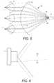
- FIG. 5illustrates a two-dimensional optical ray-trace of an exemplary embodiment, demonstrating that light from multiple LEDs merges into one overlapped image.
- FIG. 6illustrates a zoomed-in view of FIG. 5 .
- FIG. 7illustrates a two-dimensional optical ray-trace of a prior art system in which TIR (total internal reflection) lenses are used to collimate light from the LEDs.
- the light sourceis an on-axis point.
- FIG. 8illustrates a two-dimensional optical ray-trace of a prior art system in which TIR (total internal reflection) lenses are used to collimate light from the LEDs.
- the light sourceis off axis.
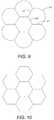
- FIG. 9illustrates a one-piece collimating lens array comprising a plurality of lens tiles in an exemplary flower-tiling configuration.
- FIG. 10illustrates a hexagonal tiling
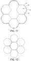
- FIG. 11illustrates that the exemplary flower-tiling configuration in FIG. 9 has a greater area at the periphery of the array than the hexagonal tiling configuration.
- FIG. 12illustrates a circular tiling
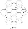
- FIG. 13illustrates a flower-tiling lens array with 13 LEDs.
- FIG. 14illustrates a plurality of LEDs imaging onto a diffuser film approximately at the focal plane of a fiber input.
- the illustrated embodimentscan be understood as providing exemplary features of varying detail of certain embodiments, and therefore, unless otherwise specified, features, components, modules, and/or aspects of the illustrations can be otherwise combined, separated, interchanged, and/or rearranged without departing from the disclosed systems or methods. Additionally, the shapes and sizes of components are also exemplary and unless otherwise specified, can be altered without affecting the scope of the disclosed and exemplary systems or methods of the present disclosure.
- FIGS. 1 and 2illustrate a cross sectional view and a perspective view, respectively, of an exemplary optical system in accordance with the present application.
- one or more light emitting diodes (LEDs) 1are mounted on an otherwise conventional circuit board 2 which provides electrical power to the LEDs 1 and aids in heat removal from the LEDs 1 .
- the disclosed lens array 3gathers and collimates light from the LEDs 1 .
- a sufficiently sized/large lens 4gathers and focuses the light onto the input 6 of a fiber-optic bundle 5 .
- the optic support housing 9serves to hold the LEDs 1 , lens array 3 , large lens 4 , and fiber optic holder 7 in relatively precise alignment.
- a lens clamp ring 8holds the large lens 4 in the optic support housing 9 .
- a fiber optic holder 7holds the fiber optic bundle 5 in relatively precise alignment with the optical system.
- the LED circuit board 2can be a metal-core circuit board having an aluminum substrate and a thin dielectric layer for LED mounting and heat removal. Heat from the LEDs 1 is transferred by conduction through the circuit board 2 to the heat sink 10 .
- the heat sink 10optionally in conjunction with a fan (not shown), serves to remove heat from the LEDs 1 to the ambient air by convection.
- the LEDs 1are arranged in a radially symmetric array, with the center of each LED 1 aligned with the central axis of each corresponding lens tile within the lens array 3 . Accordingly, there is a one-to-one correspondence between an LED 1 and a lens tile.
- the LEDs 1are mounted coplanar and the center axis of each LED 1 is approximately parallel.
- the distance from each LED 1 to each lens tileis designed to be substantially equal. Since each LED 1 is of the same type and configuration from the same manufacturer, each LED 1 will have a substantially similar emission beam pattern (source shape), within manufacturing tolerances.
- Each lens tile within the lens array 3is designed to have an identical optical profile, within manufacturing variation.
- the lens tilescan be tessellated in a “flower-tiling” geometry to form the lens array 3 .
- the large focusing lens 4converges the light from all LEDs 1 into a final image which is an overlay of all the LED images.
- the LED imageshave the same size and align on a common optical axis.
- the magnification of the systemis defined as the ratio of the image size to the LED emitting surface size.
- System magnificationis determined by the focal length of the lens tiles and the focal length of the large focusing lens. By varying these two parameters, the magnification can be adjusted so that the resulting image size matches the entrance aperture of the fiber optic. In an exemplary embodiment, the magnification is calculated to be 3.3, and the actual realized magnification is slightly greater.
- the source image of an LEDwill correspond to the generally square-shaped LED die.
- the resulting illuminance image shapeis a square.
- a calculated illuminance plot of this square-shaped illuminance image generated by optical simulationis shown in FIG. 4 .
- the magnificationmay be set such that the illuminance image 11 substantially matches the circular acceptance area 12 of the fiber optic bundle.
- Lens aberrationsincrease the Lagrangian invariant of the optical system and therefore reduce system efficiency.
- lens parametersare adjusted to reduce aberrations and increase system efficiency.
- aspheric planar-convex lens tilesmay be used for the collimating lens array. Two spherical lenses combined are sometimes used to reduce spherical aberrations, but this approach adds system complexity and cost.
- the disclosed single aspheric lens tilecan reduce spherical aberrations, reduce light loss from Fresnel surface losses, and reduce part count, weight, and cost.
- an aspheric lensmay be planar-concave, planar-convex, bi-convex, or bi-concave.
- the sourceis at the lens focal point and the image is at infinity (i.e., collimated light)
- a concave or convex lens with a nearly-planar front surfacewill result in the minimum spherical aberration.
- the LED sourceis placed at the lens focal point, and a planar-convex aspheric lens may be used for the collimating lens tile.
- plasticmay be utilized rather than glass for economical molding of the lens array.
- precision molding of a single aspheric glass lenshas existed for years, precision molding of an aspheric glass lens array is uncommon and costly.
- Plastic injection moldingoffers an accuracy comparable to glass grinding and polishing techniques at relatively low cost.
- the optic axis of each LEDis aligned with the optic axis of each corresponding lens tile. Relatively precise positioning of the lens array may be achieved with mounting and alignment features molded into the lens array.
- FIG. 5A two-dimensional optical ray-trace of an embodiment is shown in FIG. 5 , demonstrating that light from multiple LEDs 1 merges into one overlapped image, thus providing increased light output. This overlapping image also reduces color separation if different LED colors are used, such as red-green-blue-amber (RGBA) combinations, to achieve white light. Because the optic design is radially symmetrical, a two-dimensional plot is sufficiently illustrative.
- the on-axis rays 13(indicated by solid rays) start from the center of each LED 1 and end at or near the central axis of fiber optic 5 .
- the off-axis rays 14(indicated by non-solid rays) start from the edge of each LED 1 and end at or near the fiber perimeter.
- FIG. 6is a zoomed-in view of FIG. 5 , showing on-axis rays 13 and off-axis rays 14 emitted from LED 1 .
- TIRtotal internal reflection
- TIR lenses 17are generally paraboloid with a light source 16 at the lens focal point.
- the sourceis an on-axis point
- light from the TIR lenswill be well collimated and can be focused to a point 18 with an aspheric focusing lens 19 , as shown in FIG. 7 .
- the sourceis off axis, as shown in FIG. 8
- light from the TIR lensis not collimated and cannot be focused into a point. Since LEDs are extended sources, most light will be emitted off-axis and TIR lens systems cannot image an LED source without significant aberration.
- Optical systems in accordance with the present applicationuse refractive lenses to image the LED source with reduced aberrations, thus enhancing system performance.
- a one-piece collimating lens arraycomprising a plurality of lens tiles is utilized.
- the configurationis termed “flower-tiling” to distinguish it from the hexagonal or circular tiling.
- the exemplary flower-tiling configuration shown in FIG. 11has a greater area at the periphery of the array to capture light.
- the flower-tiling configurationhas a greater optical area at the interior of the array than a circular array, as shown in FIG. 12 , of similar size.
- the modified hexagonal flower tiling arrangementis preferred for maximum intensity, it should be understood that the subject invention is intended to cover systems which include more conventional circular lenses of FIG. 12 or hexagonal lenses of FIG. 10 .
- FIG. 9One exemplary flower-tiling configuration is shown in FIG. 9 .
- the flower-tiling configurationhas a hexagon tile in the center. There are six identical non-overlapping tiles surrounding and immediately adjacent to the hexagon tile in the center. Each of the six identical tiles has a first edge 20 directly abutting a corresponding edge of the hexagon tile in the center. The first edge 20 is in parallel with the corresponding edge of the hexagon tile in the center. The first edge 20 has an exact length as the corresponding edge.
- Each of the six identical tileshas a second edge 21 extending from a first end of the first edge 20 , wherein the first edge 20 and the second edge 21 have an angle of 120° between them.
- each of the six identical tileshas a third edge 22 extending from a second end of the first edge 20 , wherein the first edge 20 and the third edge 22 have an angle of 120° between them.
- each of the six identical tileshas an arc 23 connecting the ends of the second edge 21 and the third edge 22 .
- the exemplary flower-tiling configurationis a modified hexagonal tiling.
- the modification of the hexagonal tilingcomprises replacing an exterior edge 24 of an exterior hexagon 25 on the hexagonal tiling by an arc 26 connecting the two vertices 27 of the exterior edge 24 of the exterior hexagon 25 .
- Hexagon 25is an exterior hexagon on the hexagonal tiling because hexagon 25 has at least one exterior edge 24 not positioned parallel to and adjacent to an edge of another hexagon on the hexagonal tiling. Note that in the flower- tiling configuration shown in FIG. 11 , three exterior edges of each exterior hexagon on the hexagonal tiling are replaced by three corresponding arcs.
- FIG. 13shows a flower-tiling lens array with 13 LEDs.
- the flower-tiling configurationis a modified hexagonal tiling.
- the modification of the hexagonal tilingcomprises replacing an exterior edge 28 of an exterior hexagon 29 on the hexagonal tiling by an arc 30 connecting the two vertices 31 of the exterior edge 28 of the exterior hexagon 29 .
- Hexagon 29is an exterior hexagon on the hexagonal tiling because hexagon 29 has at least one exterior edge 28 not positioned parallel to and adjacent to an edge of another hexagon on the hexagonal tiling.
- the circular line 32illustrates the approximate outer diameter for light capture set by the fiber NA and the focal length of the focusing lens.
- the additional outer six LEDswill enter the fiber, even if the large lens is increased in diameter, because much of their light will fall outside the fiber acceptance angle.
- achieving a calculated flux gain of 17%requires a 46% increase in the number of LEDs, increasing the thermal load, cost, size, and electrical power requirements by a similar ratio.
- 7 LEDsare utilized to balance between the tradeoff between light output versus heat, power, size, and cost.
- an optical diffusing elementsuch as holographic diffuser film may be placed at the image plane to homogenize the light distribution.
- holographic diffuser filmmay be placed at the image plane to homogenize the light distribution.
- LEDsare imaged onto a diffuser film approximately at the fiber input. Note that the LED images are overlapped into one nearly contiguous image 33 .
- a mixing solid rod of light transmitting materialwith one end placed at the image plane and the other end adjacent to the fiber-optic entrance aperture may be used to homogenize the light distribution.
- the light outputvaries for fibers with the same NA but different diameters
- the collimating lens arraymay comprise Fresnel lenses arrayed in the inventive “flower-tiling” pattern.
- the collimating lensesmay be a planar convex lens as shown, and may also be planar concave, meniscus convex, meniscus concave, bi-convex, or bi-concave.
- the large focusing lensmay be a spherical lens, aspherical lens, or Fresnel lens.
- the number of LEDs and tiled lensesis not limited to seven, and may range from 1 to any number, but practical implementations will generally include numbers of LEDs and lenses from approximately 5 to approximately 25.
- embodiments of the present applicationare not limited to single color LEDs.
- An array of LEDs of different colorscan be used if their emitting surfaces are of approximately the same size.
- the final imagewill be an overlay image of different colors. For example, an overlay of red, green and blue may be used to produce white light.
- the embodiments of the present applicationare not limited to coupling light into fiber.
- the resulting imagemay be used as a focused high intensity spot light, task light, or examination light.
- the light sourceis not limited to light emitting diodes (LEDs). Alternatively, organic light emitting diode (OLED) or other suitable light sources may be used.
- LEDslight emitting diodes
- OLEDorganic light emitting diode
Landscapes
- Physics & Mathematics (AREA)
- General Physics & Mathematics (AREA)
- Optics & Photonics (AREA)
- Engineering & Computer Science (AREA)
- General Engineering & Computer Science (AREA)
- Led Device Packages (AREA)
- Non-Portable Lighting Devices Or Systems Thereof (AREA)
- Optical Couplings Of Light Guides (AREA)
Abstract
Description
Claims (29)
Priority Applications (1)
| Application Number | Priority Date | Filing Date | Title |
|---|---|---|---|
| US12/705,411US8408772B2 (en) | 2009-02-13 | 2010-02-12 | LED illumination device |
Applications Claiming Priority (2)
| Application Number | Priority Date | Filing Date | Title |
|---|---|---|---|
| US15229809P | 2009-02-13 | 2009-02-13 | |
| US12/705,411US8408772B2 (en) | 2009-02-13 | 2010-02-12 | LED illumination device |
Publications (2)
| Publication Number | Publication Date |
|---|---|
| US20100208487A1 US20100208487A1 (en) | 2010-08-19 |
| US8408772B2true US8408772B2 (en) | 2013-04-02 |
Family
ID=42212140
Family Applications (1)
| Application Number | Title | Priority Date | Filing Date |
|---|---|---|---|
| US12/705,411Active2031-02-05US8408772B2 (en) | 2009-02-13 | 2010-02-12 | LED illumination device |
Country Status (6)
| Country | Link |
|---|---|
| US (1) | US8408772B2 (en) |
| EP (1) | EP2396686A1 (en) |
| JP (1) | JP2012518279A (en) |
| KR (1) | KR20110118815A (en) |
| CN (1) | CN102317828A (en) |
| WO (1) | WO2010093956A1 (en) |
Cited By (23)
| Publication number | Priority date | Publication date | Assignee | Title |
|---|---|---|---|---|
| US20120224386A1 (en)* | 2011-03-04 | 2012-09-06 | Cvi Laser, Llc | On-Axis Monolithic Ellipsoidal Lens for Optical Coupling Systems |
| US20120230024A1 (en)* | 2011-03-08 | 2012-09-13 | Novadaq Technologies Inc. | Full spectrum led illuminator |
| US9642532B2 (en) | 2008-03-18 | 2017-05-09 | Novadaq Technologies Inc. | Imaging system for combined full-color reflectance and near-infrared imaging |
| US9642606B2 (en) | 2012-06-27 | 2017-05-09 | Camplex, Inc. | Surgical visualization system |
| US9681796B2 (en) | 2012-06-27 | 2017-06-20 | Camplex, Inc. | Interface for viewing video from cameras on a surgical visualization system |
| US9782159B2 (en) | 2013-03-13 | 2017-10-10 | Camplex, Inc. | Surgical visualization systems |
| US10028651B2 (en) | 2013-09-20 | 2018-07-24 | Camplex, Inc. | Surgical visualization systems and displays |
| US10568499B2 (en) | 2013-09-20 | 2020-02-25 | Camplex, Inc. | Surgical visualization systems and displays |
| US10694152B2 (en) | 2006-12-22 | 2020-06-23 | Novadaq Technologies ULC | Imaging systems and methods for displaying fluorescence and visible images |
| US10702353B2 (en) | 2014-12-05 | 2020-07-07 | Camplex, Inc. | Surgical visualizations systems and displays |
| US10869645B2 (en) | 2016-06-14 | 2020-12-22 | Stryker European Operations Limited | Methods and systems for adaptive imaging for low light signal enhancement in medical visualization |
| US10918455B2 (en) | 2017-05-08 | 2021-02-16 | Camplex, Inc. | Variable light source |
| US10966798B2 (en) | 2015-11-25 | 2021-04-06 | Camplex, Inc. | Surgical visualization systems and displays |
| USD916294S1 (en) | 2016-04-28 | 2021-04-13 | Stryker European Operations Limited | Illumination and imaging device |
| US10980420B2 (en) | 2016-01-26 | 2021-04-20 | Stryker European Operations Limited | Configurable platform |
| US10992848B2 (en) | 2017-02-10 | 2021-04-27 | Novadaq Technologies ULC | Open-field handheld fluorescence imaging systems and methods |
| US11154378B2 (en) | 2015-03-25 | 2021-10-26 | Camplex, Inc. | Surgical visualization systems and displays |
| US20220294946A1 (en)* | 2021-03-10 | 2022-09-15 | Selex Es Inc. | Systems and Methods for Vehicle Information Capture Using White Light |
| EP4311979A1 (en)* | 2022-07-27 | 2024-01-31 | Uno Minda Europe GmbH | Lighting module |
| US11930278B2 (en) | 2015-11-13 | 2024-03-12 | Stryker Corporation | Systems and methods for illumination and imaging of a target |
| US12035894B2 (en) | 2020-12-22 | 2024-07-16 | Stryker Corporation | Systems and methods for medical imaging illumination |
| US12236780B2 (en) | 2021-09-09 | 2025-02-25 | Leonardo Us Cyber And Security Solutions, Llc | Systems and methods for electronic signature tracking and analysis |
| US12347315B2 (en) | 2022-01-24 | 2025-07-01 | Leonardo Us Cyber And Security Solutions Llc | Systems and methods for parking management |
Families Citing this family (31)
| Publication number | Priority date | Publication date | Assignee | Title |
|---|---|---|---|---|
| US10008637B2 (en)* | 2011-12-06 | 2018-06-26 | Cree, Inc. | Light emitter devices and methods with reduced dimensions and improved light output |
| US20100097802A1 (en)* | 2008-10-20 | 2010-04-22 | Robe Lighting S.R.O. | Light collection system for an led luminaire |
| US8403527B2 (en)* | 2010-10-26 | 2013-03-26 | Thomas J. Brukilacchio | Light emitting diode projector |
| CN103502726A (en)* | 2011-02-23 | 2014-01-08 | 瓦维恩股份有限公司 | Light emitting diode array illumination system with recycling |
| US8888331B2 (en)* | 2011-05-09 | 2014-11-18 | Microsoft Corporation | Low inductance light source module |
| US10686107B2 (en) | 2011-07-21 | 2020-06-16 | Cree, Inc. | Light emitter devices and components with improved chemical resistance and related methods |
| US10211380B2 (en) | 2011-07-21 | 2019-02-19 | Cree, Inc. | Light emitting devices and components having improved chemical resistance and related methods |
| JP2014525146A (en) | 2011-07-21 | 2014-09-25 | クリー インコーポレイテッド | Light emitting device, package, component, and method for improved chemical resistance and related methods |
| US9496466B2 (en) | 2011-12-06 | 2016-11-15 | Cree, Inc. | Light emitter devices and methods, utilizing light emitting diodes (LEDs), for improved light extraction |
| WO2013149139A1 (en)* | 2012-03-29 | 2013-10-03 | Fraen Corporation | Tiling of multiple polygons for micro-lens array |
| JP5901036B2 (en)* | 2012-07-27 | 2016-04-06 | シャープ株式会社 | Lighting device |
| US8911130B2 (en) | 2012-11-08 | 2014-12-16 | Sunoptic Technologies, Llc | Light engine for a fiberoptic illuminator |
| JP6089616B2 (en)* | 2012-11-20 | 2017-03-08 | セイコーエプソン株式会社 | Light source device and projector |
| CN104425691A (en)* | 2013-09-02 | 2015-03-18 | 惠州市大亚湾永昶电子工业有限公司 | Light collecting structure of light source and light collecting type COB light source |
| PL410162A1 (en)* | 2014-11-17 | 2016-05-23 | Wojskowa Akademia Techniczna | LED illuminator with fibre optic output |
| US20160327721A1 (en)* | 2015-05-04 | 2016-11-10 | Corning Incorporated | Optical fiber lighting device and method |
| JP6532325B2 (en)* | 2015-07-09 | 2019-06-19 | キヤノン株式会社 | Measuring device for measuring the shape of the object to be measured |
| CN105090821B (en)* | 2015-08-03 | 2017-11-07 | 河南中医药大学 | A kind of medical endoscope checks lighting device |
| KR20170041359A (en)* | 2015-10-07 | 2017-04-17 | 엘지이노텍 주식회사 | An illumination appratus |
| GB201701355D0 (en)* | 2017-01-27 | 2017-03-15 | Renishaw Plc | Direct laser writing and chemical etching |
| US10779412B2 (en) | 2017-05-18 | 2020-09-15 | Lumileds Llc | Lighting assembly with high irradiance |
| JP6902452B2 (en) | 2017-10-19 | 2021-07-14 | 株式会社荏原製作所 | Polishing equipment |
| US10837619B2 (en) | 2018-03-20 | 2020-11-17 | Ledengin, Inc. | Optical system for multi-emitter LED-based lighting devices |
| WO2020039556A1 (en)* | 2018-08-23 | 2020-02-27 | 株式会社島津製作所 | Optical coupling device |
| JP2020042061A (en)* | 2018-09-06 | 2020-03-19 | 住友電工デバイス・イノベーション株式会社 | Light-emitting module |
| JP7110851B2 (en)* | 2018-09-10 | 2022-08-02 | セイコーエプソン株式会社 | Light source device and projector |
| CN110884253B (en)* | 2019-12-17 | 2024-09-24 | 陈诗剑 | High-strength UV-LED module system |
| US11619828B2 (en)* | 2020-01-17 | 2023-04-04 | Stmicroelectronics (Research & Development) Limited | Transmission beam splitter |
| FI130745B1 (en)* | 2020-06-22 | 2024-02-26 | Medinoa Oy | Illuminated band arrangement and method of illuminating a band structure |
| CN114721225B (en)* | 2021-01-04 | 2025-05-27 | 上海微电子装备(集团)股份有限公司 | A photolithography device and its application |
| CN115453749A (en)* | 2022-08-01 | 2022-12-09 | 安思疆科技(南京)有限公司 | Design method of 3D projector and optical lens |
Citations (36)
| Publication number | Priority date | Publication date | Assignee | Title |
|---|---|---|---|---|
| US5548676A (en) | 1993-06-29 | 1996-08-20 | Savage, Jr.; John M. | Light pipe optical coupling between led and fiber optics cable |
| US5634711A (en) | 1993-09-13 | 1997-06-03 | Kennedy; John | Portable light emitting apparatus with a semiconductor emitter array |
| US5751869A (en)* | 1996-08-08 | 1998-05-12 | Cogent Light Technologies, Inc. | Optical system for coupling light from a single fiber optic into a fiber bundle |
| US5815624A (en) | 1996-08-30 | 1998-09-29 | Rosenberg; Gary J. | Optical fiber viewing apparatus |
| US5997150A (en) | 1995-10-25 | 1999-12-07 | Texas Instruments Incorporated | Multiple emitter illuminator engine |
| US6253006B1 (en) | 1999-10-28 | 2001-06-26 | Radiant Optics, Inc. | Directing and organizing lens means for a fiber optics network |
| US6272269B1 (en) | 1999-11-16 | 2001-08-07 | Dn Labs Inc. | Optical fiber/waveguide illumination system |
| US20010019378A1 (en) | 2000-02-14 | 2001-09-06 | Akira Yamaguchi | Collimating plate, lighting apparatus and liquid crystal display apparatus |
| US6290382B1 (en)* | 1998-08-17 | 2001-09-18 | Ppt Vision, Inc. | Fiber bundle combiner and led illumination system and method |
| US6328484B1 (en) | 2000-03-02 | 2001-12-11 | Agilent Technologies, Inc. | Fiber optic lens system for coupling fibers to surface mounted devices |
| US20020001140A1 (en) | 1999-11-23 | 2002-01-03 | Radiant Optics, Inc. | Collecting and organizing means for multiple light sources |
| US6402347B1 (en) | 1998-12-17 | 2002-06-11 | Koninklijke Philips Electronics N.V. | Light generator for introducing light into a bundle of optical fibers |
| US6443594B1 (en) | 2000-03-31 | 2002-09-03 | Koninklijke Philips Electronics N.V. | One-piece lens arrays for collimating and focusing light and led light generators using same |
| US6560038B1 (en) | 2001-12-10 | 2003-05-06 | Teledyne Lighting And Display Products, Inc. | Light extraction from LEDs with light pipes |
| US20030112639A1 (en) | 2001-12-18 | 2003-06-19 | Michael Stack | LED based optical fiber illuminator and controller |
| US6595674B1 (en) | 1998-07-02 | 2003-07-22 | Ccs Inc. | Lighting device for surface inspection |
| US20030231843A1 (en) | 2002-06-13 | 2003-12-18 | Colombo Joseph G. | Fiber optic light compressor for a curing instrument |
| US6692431B2 (en) | 2001-09-07 | 2004-02-17 | Smith & Nephew, Inc. | Endoscopic system with a solid-state light source |
| US6816241B2 (en) | 2000-09-26 | 2004-11-09 | Sensys Medical, Inc. | LED light source-based instrument for non-invasive blood analyte determination |
| US6826336B2 (en) | 2002-05-22 | 2004-11-30 | The Boeing Company | Fiber optic LED illuminator |
| US6880954B2 (en) | 2002-11-08 | 2005-04-19 | Smd Software, Inc. | High intensity photocuring system |
| US6902310B2 (en) | 2002-02-01 | 2005-06-07 | Samsung Electronics Co., Ltd. | Illumination system and projection display device employing the same |
| US6921920B2 (en) | 2001-08-31 | 2005-07-26 | Smith & Nephew, Inc. | Solid-state light source |
| WO2006032160A1 (en) | 2004-09-21 | 2006-03-30 | Volpi Ag | Illumination source |
| US7029277B2 (en) | 2002-10-17 | 2006-04-18 | Coltene / Whaledent Inc. | Curing light with engineered spectrum and power compressor guide |
| DE102004051382A1 (en) | 2004-10-21 | 2006-04-27 | Oec Ag | Microlens array |
| DE102005017238A1 (en) | 2005-04-14 | 2006-10-19 | Zett Optics Gmbh | Electromagnetic radiation superimposing device, for use in lighting system, has conical optical component, which collimates cone mantle shaped beam from fiber optic unit, where collimated beam is concentrated on specific area |
| US7163327B2 (en) | 2002-12-02 | 2007-01-16 | 3M Innovative Properties Company | Illumination system using a plurality of light sources |
| US7182497B2 (en) | 2004-09-24 | 2007-02-27 | Samsung Electronics Co., Ltd. | Illumination unit using LED and image projecting apparatus employing the same |
| US7182496B2 (en) | 2004-04-14 | 2007-02-27 | Opto Technology, Inc. | Multiple LED focused lighting device |
| US20070053200A1 (en) | 2001-12-31 | 2007-03-08 | Brukilacchio Thomas J | High intensity LED array illuminator |
| US20070086205A1 (en) | 2003-03-26 | 2007-04-19 | Optim, Inc. | Compact, high efficiency, high power solid state light source using a solid state light-emitting device |
| US7250611B2 (en) | 2003-12-02 | 2007-07-31 | 3M Innovative Properties Company | LED curing apparatus and method |
| US7300177B2 (en)* | 2004-02-11 | 2007-11-27 | 3M Innovative Properties | Illumination system having a plurality of light source modules disposed in an array with a non-radially symmetrical aperture |
| US20070275344A1 (en) | 2005-02-26 | 2007-11-29 | Yongqian Liu | LED Curing Light having Fresnel Lenses |
| US20080310182A1 (en) | 2007-06-12 | 2008-12-18 | Schott Ag | Device For Coupling Light Into a Fiber-Optic Optical Waveguide |
Family Cites Families (3)
| Publication number | Priority date | Publication date | Assignee | Title |
|---|---|---|---|---|
| GB0030410D0 (en)* | 2000-12-13 | 2001-01-24 | Screen Technology Ltd | Collimator |
| KR100656996B1 (en)* | 2004-09-03 | 2006-12-13 | 엘지전자 주식회사 | Microlens Array Projection Screen |
| CN201194029Y (en)* | 2008-04-18 | 2009-02-11 | 徐秋霜 | Construction of self-focusing lens glass array |
- 2010
- 2010-02-12KRKR1020117021261Apatent/KR20110118815A/ennot_activeWithdrawn
- 2010-02-12EPEP10708440Apatent/EP2396686A1/ennot_activeCeased
- 2010-02-12WOPCT/US2010/024141patent/WO2010093956A1/enactiveApplication Filing
- 2010-02-12USUS12/705,411patent/US8408772B2/enactiveActive
- 2010-02-12CNCN2010800073286Apatent/CN102317828A/enactivePending
- 2010-02-12JPJP2011550281Apatent/JP2012518279A/enactivePending
Patent Citations (41)
| Publication number | Priority date | Publication date | Assignee | Title |
|---|---|---|---|---|
| US5548676A (en) | 1993-06-29 | 1996-08-20 | Savage, Jr.; John M. | Light pipe optical coupling between led and fiber optics cable |
| US5634711A (en) | 1993-09-13 | 1997-06-03 | Kennedy; John | Portable light emitting apparatus with a semiconductor emitter array |
| US5997150A (en) | 1995-10-25 | 1999-12-07 | Texas Instruments Incorporated | Multiple emitter illuminator engine |
| US5751869A (en)* | 1996-08-08 | 1998-05-12 | Cogent Light Technologies, Inc. | Optical system for coupling light from a single fiber optic into a fiber bundle |
| US5815624A (en) | 1996-08-30 | 1998-09-29 | Rosenberg; Gary J. | Optical fiber viewing apparatus |
| US6595674B1 (en) | 1998-07-02 | 2003-07-22 | Ccs Inc. | Lighting device for surface inspection |
| US6290382B1 (en)* | 1998-08-17 | 2001-09-18 | Ppt Vision, Inc. | Fiber bundle combiner and led illumination system and method |
| US6402347B1 (en) | 1998-12-17 | 2002-06-11 | Koninklijke Philips Electronics N.V. | Light generator for introducing light into a bundle of optical fibers |
| US6253006B1 (en) | 1999-10-28 | 2001-06-26 | Radiant Optics, Inc. | Directing and organizing lens means for a fiber optics network |
| US6272269B1 (en) | 1999-11-16 | 2001-08-07 | Dn Labs Inc. | Optical fiber/waveguide illumination system |
| US20020001140A1 (en) | 1999-11-23 | 2002-01-03 | Radiant Optics, Inc. | Collecting and organizing means for multiple light sources |
| US6876408B2 (en) | 2000-02-14 | 2005-04-05 | Fuji Photo Film Co., Ltd. | Collimating plate, lighting apparatus and liquid crystal display apparatus |
| US20010019378A1 (en) | 2000-02-14 | 2001-09-06 | Akira Yamaguchi | Collimating plate, lighting apparatus and liquid crystal display apparatus |
| US6328484B1 (en) | 2000-03-02 | 2001-12-11 | Agilent Technologies, Inc. | Fiber optic lens system for coupling fibers to surface mounted devices |
| US6443594B1 (en) | 2000-03-31 | 2002-09-03 | Koninklijke Philips Electronics N.V. | One-piece lens arrays for collimating and focusing light and led light generators using same |
| US6816241B2 (en) | 2000-09-26 | 2004-11-09 | Sensys Medical, Inc. | LED light source-based instrument for non-invasive blood analyte determination |
| US7959338B2 (en)* | 2001-08-31 | 2011-06-14 | Smith & Nephew, Inc. | Solid-state light source |
| US7345312B2 (en)* | 2001-08-31 | 2008-03-18 | Smith & Nephew, Inc. | Solid-state light source |
| US6921920B2 (en) | 2001-08-31 | 2005-07-26 | Smith & Nephew, Inc. | Solid-state light source |
| US6692431B2 (en) | 2001-09-07 | 2004-02-17 | Smith & Nephew, Inc. | Endoscopic system with a solid-state light source |
| US7063663B2 (en) | 2001-09-07 | 2006-06-20 | Smith & Nephew, Inc. | Endoscopic system with a solid-state light source |
| US6560038B1 (en) | 2001-12-10 | 2003-05-06 | Teledyne Lighting And Display Products, Inc. | Light extraction from LEDs with light pipes |
| US20030112639A1 (en) | 2001-12-18 | 2003-06-19 | Michael Stack | LED based optical fiber illuminator and controller |
| US20070053200A1 (en) | 2001-12-31 | 2007-03-08 | Brukilacchio Thomas J | High intensity LED array illuminator |
| US6902310B2 (en) | 2002-02-01 | 2005-06-07 | Samsung Electronics Co., Ltd. | Illumination system and projection display device employing the same |
| US6826336B2 (en) | 2002-05-22 | 2004-11-30 | The Boeing Company | Fiber optic LED illuminator |
| US20030231843A1 (en) | 2002-06-13 | 2003-12-18 | Colombo Joseph G. | Fiber optic light compressor for a curing instrument |
| US7029277B2 (en) | 2002-10-17 | 2006-04-18 | Coltene / Whaledent Inc. | Curing light with engineered spectrum and power compressor guide |
| US6880954B2 (en) | 2002-11-08 | 2005-04-19 | Smd Software, Inc. | High intensity photocuring system |
| US7163327B2 (en) | 2002-12-02 | 2007-01-16 | 3M Innovative Properties Company | Illumination system using a plurality of light sources |
| US20070086205A1 (en) | 2003-03-26 | 2007-04-19 | Optim, Inc. | Compact, high efficiency, high power solid state light source using a solid state light-emitting device |
| US7250611B2 (en) | 2003-12-02 | 2007-07-31 | 3M Innovative Properties Company | LED curing apparatus and method |
| US7300177B2 (en)* | 2004-02-11 | 2007-11-27 | 3M Innovative Properties | Illumination system having a plurality of light source modules disposed in an array with a non-radially symmetrical aperture |
| US7182496B2 (en) | 2004-04-14 | 2007-02-27 | Opto Technology, Inc. | Multiple LED focused lighting device |
| WO2006032160A1 (en) | 2004-09-21 | 2006-03-30 | Volpi Ag | Illumination source |
| US7182497B2 (en) | 2004-09-24 | 2007-02-27 | Samsung Electronics Co., Ltd. | Illumination unit using LED and image projecting apparatus employing the same |
| DE102004051382A1 (en) | 2004-10-21 | 2006-04-27 | Oec Ag | Microlens array |
| WO2006045545A1 (en) | 2004-10-21 | 2006-05-04 | Oec Ag | Lens and microlens array |
| US20070275344A1 (en) | 2005-02-26 | 2007-11-29 | Yongqian Liu | LED Curing Light having Fresnel Lenses |
| DE102005017238A1 (en) | 2005-04-14 | 2006-10-19 | Zett Optics Gmbh | Electromagnetic radiation superimposing device, for use in lighting system, has conical optical component, which collimates cone mantle shaped beam from fiber optic unit, where collimated beam is concentrated on specific area |
| US20080310182A1 (en) | 2007-06-12 | 2008-12-18 | Schott Ag | Device For Coupling Light Into a Fiber-Optic Optical Waveguide |
Non-Patent Citations (2)
| Title |
|---|
| International Preliminary report on Patentability received for PCT Patent Application No. PCT/US2010/024141, mailed on Aug. 25, 2011, 7 pages. |
| International Search Report and Written Opinion received for PCT Patent Application No. PCT/US2010/024141, mailed on Jun. 23, 2010, 12 pages. |
Cited By (51)
| Publication number | Priority date | Publication date | Assignee | Title |
|---|---|---|---|---|
| US10694152B2 (en) | 2006-12-22 | 2020-06-23 | Novadaq Technologies ULC | Imaging systems and methods for displaying fluorescence and visible images |
| US11770503B2 (en) | 2006-12-22 | 2023-09-26 | Stryker European Operations Limited | Imaging systems and methods for displaying fluorescence and visible images |
| US11025867B2 (en) | 2006-12-22 | 2021-06-01 | Stryker European Operations Limited | Imaging systems and methods for displaying fluorescence and visible images |
| US10694151B2 (en) | 2006-12-22 | 2020-06-23 | Novadaq Technologies ULC | Imaging system with a single color image sensor for simultaneous fluorescence and color video endoscopy |
| US9642532B2 (en) | 2008-03-18 | 2017-05-09 | Novadaq Technologies Inc. | Imaging system for combined full-color reflectance and near-infrared imaging |
| US10779734B2 (en) | 2008-03-18 | 2020-09-22 | Stryker European Operations Limited | Imaging system for combine full-color reflectance and near-infrared imaging |
| US8511876B2 (en)* | 2011-03-04 | 2013-08-20 | Cvi Laser, Llc | On-axis monolithic ellipsoidal lens for optical coupling systems |
| US20120224386A1 (en)* | 2011-03-04 | 2012-09-06 | Cvi Laser, Llc | On-Axis Monolithic Ellipsoidal Lens for Optical Coupling Systems |
| US20120230024A1 (en)* | 2011-03-08 | 2012-09-13 | Novadaq Technologies Inc. | Full spectrum led illuminator |
| US8979301B2 (en)* | 2011-03-08 | 2015-03-17 | Novadaq Technologies Inc. | Full spectrum LED illuminator |
| US9435496B2 (en) | 2011-03-08 | 2016-09-06 | Novadaq Technologies Inc. | Full spectrum LED illuminator |
| US9814378B2 (en) | 2011-03-08 | 2017-11-14 | Novadaq Technologies Inc. | Full spectrum LED illuminator having a mechanical enclosure and heatsink |
| US10925589B2 (en) | 2012-06-27 | 2021-02-23 | Camplex, Inc. | Interface for viewing video from cameras on a surgical visualization system |
| US9642606B2 (en) | 2012-06-27 | 2017-05-09 | Camplex, Inc. | Surgical visualization system |
| US10231607B2 (en) | 2012-06-27 | 2019-03-19 | Camplex, Inc. | Surgical visualization systems |
| US10555728B2 (en) | 2012-06-27 | 2020-02-11 | Camplex, Inc. | Surgical visualization system |
| US11889976B2 (en) | 2012-06-27 | 2024-02-06 | Camplex, Inc. | Surgical visualization systems |
| US10022041B2 (en) | 2012-06-27 | 2018-07-17 | Camplex, Inc. | Hydraulic system for surgical applications |
| US9936863B2 (en) | 2012-06-27 | 2018-04-10 | Camplex, Inc. | Optical assembly providing a surgical microscope view for a surgical visualization system |
| US9681796B2 (en) | 2012-06-27 | 2017-06-20 | Camplex, Inc. | Interface for viewing video from cameras on a surgical visualization system |
| US9723976B2 (en) | 2012-06-27 | 2017-08-08 | Camplex, Inc. | Optics for video camera on a surgical visualization system |
| US11389146B2 (en) | 2012-06-27 | 2022-07-19 | Camplex, Inc. | Surgical visualization system |
| US11166706B2 (en) | 2012-06-27 | 2021-11-09 | Camplex, Inc. | Surgical visualization systems |
| US11129521B2 (en) | 2012-06-27 | 2021-09-28 | Camplex, Inc. | Optics for video camera on a surgical visualization system |
| US10925472B2 (en) | 2012-06-27 | 2021-02-23 | Camplex, Inc. | Binocular viewing assembly for a surgical visualization system |
| US9782159B2 (en) | 2013-03-13 | 2017-10-10 | Camplex, Inc. | Surgical visualization systems |
| US10932766B2 (en) | 2013-05-21 | 2021-03-02 | Camplex, Inc. | Surgical visualization systems |
| US10881286B2 (en) | 2013-09-20 | 2021-01-05 | Camplex, Inc. | Medical apparatus for use with a surgical tubular retractor |
| US11147443B2 (en) | 2013-09-20 | 2021-10-19 | Camplex, Inc. | Surgical visualization systems and displays |
| US10568499B2 (en) | 2013-09-20 | 2020-02-25 | Camplex, Inc. | Surgical visualization systems and displays |
| US10028651B2 (en) | 2013-09-20 | 2018-07-24 | Camplex, Inc. | Surgical visualization systems and displays |
| US10702353B2 (en) | 2014-12-05 | 2020-07-07 | Camplex, Inc. | Surgical visualizations systems and displays |
| US11154378B2 (en) | 2015-03-25 | 2021-10-26 | Camplex, Inc. | Surgical visualization systems and displays |
| US11930278B2 (en) | 2015-11-13 | 2024-03-12 | Stryker Corporation | Systems and methods for illumination and imaging of a target |
| US10966798B2 (en) | 2015-11-25 | 2021-04-06 | Camplex, Inc. | Surgical visualization systems and displays |
| US11298024B2 (en) | 2016-01-26 | 2022-04-12 | Stryker European Operations Limited | Configurable platform |
| US10980420B2 (en) | 2016-01-26 | 2021-04-20 | Stryker European Operations Limited | Configurable platform |
| USD916294S1 (en) | 2016-04-28 | 2021-04-13 | Stryker European Operations Limited | Illumination and imaging device |
| USD1065550S1 (en) | 2016-04-28 | 2025-03-04 | Stryker Corporation | Device for illumination and imaging of a target |
| USD977480S1 (en) | 2016-04-28 | 2023-02-07 | Stryker European Operations Limited | Device for illumination and imaging of a target |
| US10869645B2 (en) | 2016-06-14 | 2020-12-22 | Stryker European Operations Limited | Methods and systems for adaptive imaging for low light signal enhancement in medical visualization |
| US11756674B2 (en) | 2016-06-14 | 2023-09-12 | Stryker European Operations Limited | Methods and systems for adaptive imaging for low light signal enhancement in medical visualization |
| US11140305B2 (en) | 2017-02-10 | 2021-10-05 | Stryker European Operations Limited | Open-field handheld fluorescence imaging systems and methods |
| US12028600B2 (en) | 2017-02-10 | 2024-07-02 | Stryker Corporation | Open-field handheld fluorescence imaging systems and methods |
| US10992848B2 (en) | 2017-02-10 | 2021-04-27 | Novadaq Technologies ULC | Open-field handheld fluorescence imaging systems and methods |
| US10918455B2 (en) | 2017-05-08 | 2021-02-16 | Camplex, Inc. | Variable light source |
| US12035894B2 (en) | 2020-12-22 | 2024-07-16 | Stryker Corporation | Systems and methods for medical imaging illumination |
| US20220294946A1 (en)* | 2021-03-10 | 2022-09-15 | Selex Es Inc. | Systems and Methods for Vehicle Information Capture Using White Light |
| US12236780B2 (en) | 2021-09-09 | 2025-02-25 | Leonardo Us Cyber And Security Solutions, Llc | Systems and methods for electronic signature tracking and analysis |
| US12347315B2 (en) | 2022-01-24 | 2025-07-01 | Leonardo Us Cyber And Security Solutions Llc | Systems and methods for parking management |
| EP4311979A1 (en)* | 2022-07-27 | 2024-01-31 | Uno Minda Europe GmbH | Lighting module |
Also Published As
| Publication number | Publication date |
|---|---|
| JP2012518279A (en) | 2012-08-09 |
| EP2396686A1 (en) | 2011-12-21 |
| WO2010093956A1 (en) | 2010-08-19 |
| KR20110118815A (en) | 2011-11-01 |
| US20100208487A1 (en) | 2010-08-19 |
| CN102317828A (en) | 2012-01-11 |
Similar Documents
| Publication | Publication Date | Title |
|---|---|---|
| US8408772B2 (en) | LED illumination device | |
| US11339948B2 (en) | Light-emitting device and luminaire incorporating same | |
| US9217552B2 (en) | Illumination device | |
| US10295153B2 (en) | Optical system for producing uniform illumination | |
| JP6113872B2 (en) | Ring light illuminators and beam shapers for ring light illuminators | |
| EP2856236B1 (en) | Collimation and homogenization system for an led luminaire | |
| JP6096180B2 (en) | Light emitting diode light source | |
| EP3366990B1 (en) | Led lamp | |
| US9229145B2 (en) | Lighting device | |
| KR101189652B1 (en) | LED array type for the lighting lens and the lens using the same | |
| US20070047092A1 (en) | LED light converging system | |
| US20110235360A1 (en) | Light source device for supplying light to fiber optic illumination system | |
| JP7500572B2 (en) | Ophthalmic Light Source | |
| JP5097798B2 (en) | Fiber optic lighting equipment | |
| CN210568180U (en) | High-uniformity LED lens module, light-emitting structure and LED lamp |
Legal Events
| Date | Code | Title | Description |
|---|---|---|---|
| AS | Assignment | Owner name:PERKINELMER LED SOLUTIONS, INC., ILLINOIS Free format text:ASSIGNMENT OF ASSIGNORS INTEREST;ASSIGNOR:LI, WEI;REEL/FRAME:024165/0914 Effective date:20100302 | |
| AS | Assignment | Owner name:PERKINELMER LED SOLUTIONS, INC., ILLINOIS Free format text:CHANGE OF NAME;ASSIGNOR:OPTO TECHNOLOGY INC.;REEL/FRAME:025092/0634 Effective date:20091001 | |
| AS | Assignment | Owner name:UBS AG, STAMFORD BRANCH, CONNECTICUT Free format text:SECURITY AGREEMENT;ASSIGNORS:PERKINELMER SENSORS, INC.;PERKINELMER ILLUMINATION, INC.;PERKINELMER LED SOLUTIONS, INC.;REEL/FRAME:025814/0276 Effective date:20101129 | |
| AS | Assignment | Owner name:EXCELITAS TECHOLOGIES LED SOLUTIONS, INC., ILLINOI Free format text:CHANGE OF NAME;ASSIGNOR:PERKINELMER LED SOLUTIONS, INC.;REEL/FRAME:027009/0038 Effective date:20101129 | |
| AS | Assignment | Owner name:EXCELITAS TECHNOLOGIES LED SOLUTIONS, INC., ILLINO Free format text:CORRECTIVE ASSIGNMENT TO CORRECT THE NAME OF THE ASSIGNEE PREVIOUSLY RECORDED ON REEL 027009 FRAME 0038. ASSIGNOR(S) HEREBY CONFIRMS THE ASSIGNMENT TO EXCELITAS TECHNOLOGIES LED SOLUTIONS, INC.;ASSIGNOR:PERKINELMER LED SOLUTIONS, INC.;REEL/FRAME:027015/0498 Effective date:20101129 | |
| STCF | Information on status: patent grant | Free format text:PATENTED CASE | |
| AS | Assignment | Owner name:EXCELITAS TECHNOLOGIES CORP., MASSACHUSETTS Free format text:MERGER;ASSIGNORS:EXCELITAS TECHNOLOGIES SENSORS, INC.;EXCELITAS TECHNOLOGIES CORP.;REEL/FRAME:030187/0661 Effective date:20121217 Owner name:EXCELITAS TECHNOLOGIES SENSORS, INC., MASSACHUSETT Free format text:MERGER;ASSIGNORS:EXCELITAS TECHNOLOGIES ILLUMINATION, INC.;EXCELITAS TECHNOLOGIES LED SOLUTIONS, INC.;EXCELITAS TECHNOLOGIES SENSORS, INC.;AND OTHERS;REEL/FRAME:030187/0480 Effective date:20121217 | |
| AS | Assignment | Owner name:UBS AG, STAMFORD BRANCH, CONNECTICUT Free format text:FIRST LIEN PATENT SECURITY AGREEMENT;ASSIGNOR:EXCELITAS TECHNOLOGIES CORP.;REEL/FRAME:031558/0873 Effective date:20131031 | |
| AS | Assignment | Owner name:EXCELITAS TECHNOLOGIES CORP. (SUCCESSOR-IN-INTERES Free format text:RELEASE OF PATENT SECURITY AGREEMENT RECORDED AT REEL 025814/FRAME 0276;ASSIGNOR:UBS AG, STAMFORD BRANCH;REEL/FRAME:031626/0852 Effective date:20131031 | |
| AS | Assignment | Owner name:CREDIT SUISSE AG, CAYMAN ISLANDS BRANCH, AS COLLAT Free format text:SECOND LIEN PATENT SECURITY AGREEMENT;ASSIGNOR:EXCELITAS TECHNOLOGIES CORP.;REEL/FRAME:032086/0605 Effective date:20131031 | |
| AS | Assignment | Owner name:CORTLAND PRODUCTS CORP., AS SUCCESSOR AGENT, ILLIN Free format text:ASSIGNMENT OF SECURITY INTEREST IN PATENTS SECOND LIEN;ASSIGNOR:CREDIT SUISSE AG, CAYMAN ISLANDS BRANCH, AS EXISTING AGENT;REEL/FRAME:040043/0135 Effective date:20160914 | |
| FPAY | Fee payment | Year of fee payment:4 | |
| AS | Assignment | Owner name:EXCELITAS TECHNOLOGIES CORP., MASSACHUSETTS Free format text:RELEASE BY SECURED PARTY;ASSIGNOR:CORTLAND PRODUCTS CORP.;REEL/FRAME:044591/0966 Effective date:20171201 Owner name:EXCELITAS TECHNOLOGIES CORP., MASSACHUSETTS Free format text:RELEASE OF FIRST LIEN SECURITY INTEREST IN PATENTS RECORDED AT REEL 031558/FRAME 0873;ASSIGNOR:UBS AG, STAMFORD BRANCH;REEL/FRAME:044621/0082 Effective date:20171201 | |
| AS | Assignment | Owner name:JPMORGAN CHASE BANK, N.A., AS COLLATERAL AGENT, ILLINOIS Free format text:FIRST LIEN INTELLECTUAL PROPERTY SECURITY AGREEMENT;ASSIGNOR:EXCELITAS TECHNOLOGIES CORP.;REEL/FRAME:044695/0525 Effective date:20171201 Owner name:ROYAL BANK OF CANADA, AS COLLATERAL AGENT, NEW YORK Free format text:SECOND LIEN INTELLECTUAL PROPERTY SECURITY AGREEMENT;ASSIGNOR:EXCELITAS TECHNOLOGIES CORP.;REEL/FRAME:044695/0780 Effective date:20171201 Owner name:ROYAL BANK OF CANADA, AS COLLATERAL AGENT, NEW YOR Free format text:SECOND LIEN INTELLECTUAL PROPERTY SECURITY AGREEMENT;ASSIGNOR:EXCELITAS TECHNOLOGIES CORP.;REEL/FRAME:044695/0780 Effective date:20171201 Owner name:JPMORGAN CHASE BANK, N.A., AS COLLATERAL AGENT, IL Free format text:FIRST LIEN INTELLECTUAL PROPERTY SECURITY AGREEMENT;ASSIGNOR:EXCELITAS TECHNOLOGIES CORP.;REEL/FRAME:044695/0525 Effective date:20171201 | |
| MAFP | Maintenance fee payment | Free format text:PAYMENT OF MAINTENANCE FEE, 8TH YEAR, LARGE ENTITY (ORIGINAL EVENT CODE: M1552); ENTITY STATUS OF PATENT OWNER: LARGE ENTITY Year of fee payment:8 | |
| AS | Assignment | Owner name:EXCELITAS CANADA, INC., CANADA Free format text:ASSIGNMENT OF ASSIGNORS INTEREST;ASSIGNOR:EXCELITAS TECHNOLOGIES CORP.;REEL/FRAME:056299/0696 Effective date:20210504 | |
| AS | Assignment | Owner name:EXCELITAS TECHNOLOGIES CORP., MASSACHUSETTS Free format text:RELEASE OF FIRST LIEN SECURITY INTEREST IN INTELLECTUAL PROPERTY;ASSIGNOR:JPMORGAN CHASE BANK, N.A., AS COLLATERAL AGENT;REEL/FRAME:061161/0607 Effective date:20220811 Owner name:GOLUB CAPITAL MARKETS LLC, AS COLLATERAL AGENT, ILLINOIS Free format text:SECURITY INTEREST;ASSIGNOR:EXCELITAS CANADA INC.;REEL/FRAME:061161/0079 Effective date:20220812 Owner name:EXCELITAS TECHNOLOGIES CORP., MASSACHUSETTS Free format text:RELEASE OF SECOND LIEN SECURITY INTEREST IN INTELLECTUAL PROPERTY;ASSIGNOR:ROYAL BANK OF CANADA, AS COLLATERAL AGENT;REEL/FRAME:061161/0685 Effective date:20220811 | |
| MAFP | Maintenance fee payment | Free format text:PAYMENT OF MAINTENANCE FEE, 12TH YEAR, LARGE ENTITY (ORIGINAL EVENT CODE: M1553); ENTITY STATUS OF PATENT OWNER: LARGE ENTITY Year of fee payment:12 |