US8408737B2 - Light emitting diode sign lighter - Google Patents
Light emitting diode sign lighterDownload PDFInfo
- Publication number
- US8408737B2 US8408737B2US12/721,204US72120410AUS8408737B2US 8408737 B2US8408737 B2US 8408737B2US 72120410 AUS72120410 AUS 72120410AUS 8408737 B2US8408737 B2US 8408737B2
- Authority
- US
- United States
- Prior art keywords
- led
- sign
- housing
- leds
- modules
- Prior art date
- Legal status (The legal status is an assumption and is not a legal conclusion. Google has not performed a legal analysis and makes no representation as to the accuracy of the status listed.)
- Active, expires
Links
Images


Classifications
- G—PHYSICS
- G09—EDUCATION; CRYPTOGRAPHY; DISPLAY; ADVERTISING; SEALS
- G09F—DISPLAYING; ADVERTISING; SIGNS; LABELS OR NAME-PLATES; SEALS
- G09F9/00—Indicating arrangements for variable information in which the information is built-up on a support by selection or combination of individual elements
- G09F9/30—Indicating arrangements for variable information in which the information is built-up on a support by selection or combination of individual elements in which the desired character or characters are formed by combining individual elements
- G09F9/33—Indicating arrangements for variable information in which the information is built-up on a support by selection or combination of individual elements in which the desired character or characters are formed by combining individual elements being semiconductor devices, e.g. diodes
- F—MECHANICAL ENGINEERING; LIGHTING; HEATING; WEAPONS; BLASTING
- F21—LIGHTING
- F21S—NON-PORTABLE LIGHTING DEVICES; SYSTEMS THEREOF; VEHICLE LIGHTING DEVICES SPECIALLY ADAPTED FOR VEHICLE EXTERIORS
- F21S2/00—Systems of lighting devices, not provided for in main groups F21S4/00 - F21S10/00 or F21S19/00, e.g. of modular construction
- F21S2/005—Systems of lighting devices, not provided for in main groups F21S4/00 - F21S10/00 or F21S19/00, e.g. of modular construction of modular construction
- G—PHYSICS
- G09—EDUCATION; CRYPTOGRAPHY; DISPLAY; ADVERTISING; SEALS
- G09F—DISPLAYING; ADVERTISING; SIGNS; LABELS OR NAME-PLATES; SEALS
- G09F13/00—Illuminated signs; Luminous advertising
- G09F13/20—Illuminated signs; Luminous advertising with luminescent surfaces or parts
- G09F13/22—Illuminated signs; Luminous advertising with luminescent surfaces or parts electroluminescent
- F—MECHANICAL ENGINEERING; LIGHTING; HEATING; WEAPONS; BLASTING
- F21—LIGHTING
- F21Y—INDEXING SCHEME ASSOCIATED WITH SUBCLASSES F21K, F21L, F21S and F21V, RELATING TO THE FORM OR THE KIND OF THE LIGHT SOURCES OR OF THE COLOUR OF THE LIGHT EMITTED
- F21Y2105/00—Planar light sources
- F21Y2105/10—Planar light sources comprising a two-dimensional array of point-like light-generating elements
- F—MECHANICAL ENGINEERING; LIGHTING; HEATING; WEAPONS; BLASTING
- F21—LIGHTING
- F21Y—INDEXING SCHEME ASSOCIATED WITH SUBCLASSES F21K, F21L, F21S and F21V, RELATING TO THE FORM OR THE KIND OF THE LIGHT SOURCES OR OF THE COLOUR OF THE LIGHT EMITTED
- F21Y2115/00—Light-generating elements of semiconductor light sources
- F21Y2115/10—Light-emitting diodes [LED]
Definitions
- the present inventionrelates generally to luminaires. More specifically, the embodiments of the invention relate to a sign lighter luminaire with LED light sources.
- LEDsLight emitting diodes
- LEDsare a type of semi-conductor device that emits visible light when biased in the forward direction. LEDs are typically smaller than standard bulb or filament type lamps, making LEDs desirable in applications where space is limited. A single LED typically produces less illumination than that of a standard light bulb. Therefore, in some applications, a plurality of LEDs may be combined in an array or other fashion to provide the same degree of illumination provided by one or more standard conventional lamps.
- LEDstypically produce consistent and clear light that is more pleasant than conventional lamps. Also, unlike standard bulb lamps, LEDs do not have a high fail rate because they do not require a filament to produce light. Instead, light emitted by a LED is created by the generation of photons from materials within the LED. Accordingly, striations—which are present in convention filament-produced light sources—are not present with LEDs.
- a lightmay be used by a government agency or commercial business, for example, to illuminate a sign along a roadway.
- Assemblies used for this purposeare typically called sign lighters.
- Conventional sign lighterstypically comprise a housing containing a single lamp, such as a metal halide lamp.
- the conventional sign lighteris typically held perpendicular to the sign so as to direct light upwards to illuminate the sign. In this way, the sign may be read at night or during dark portions of the day.
- conventional sign lightershave additional problems such as excessive light spill (i.e., the light emitted from the sign lighter illuminates areas beyond the dimensions of the sign that are not intended to be illuminated) and striations. Additionally, the short life of bulbs and the effect of the light provided from conventional bulbs tend to wane over time. The color produced by conventional sign lighters, for example, has an undesirable yellow tint that becomes increasingly more pronounced and less desirable to users over time.
- LEDsare generally more energy efficient, more reliable, and last longer than conventional types of lighting, such as metal halide lamps.
- LEDshave heretofore not been incorporated into applications to provide light for illuminating signs or for other commercial or governmental applications, such as street lamps. Further, LEDs have not been incorporated into a housing or system which can be retrofitted to replace existing metal halide and other conventional sign lighters.
- the inventive LED sign lighter described hereinsolves the aforementioned problems by providing an efficient, long-lasting, non-striated, and pleasant light source for illuminating a variety of applications, including but not limited to, lighting sides of buildings, Department of Transportation roadway signs, and commercial or governmental billboard signs.
- the inventive LED sign lightermay include an assembly for housing one or more LED modules, one or more electrical drivers to power the LED modules, and a heat sink preferably molded into the assembly to help alleviate heat caused by the normal use of one or more LEDs in each LED module.
- each LED module or quadrantincludes an array of LEDs connected to an electrical source, such as an electrical driver supplying power to each LED module.
- the LED modulemay further include one or more reflectors or over-optics to control the angle of the light emitted from each LED.
- the modulemay also include a cover for protecting the LEDs, as well as other features, such as a gasket and frame to prevent rain, sleet, or snow from entering the area where the LEDs are maintained.
- Each LED modulemay include any number of LEDs in any number of arrays. In an exemplary embodiment, an array of 4 ⁇ 5 LEDs may be used for a LED module.
- the assembly for the LED sign lighterpreferably is a diecast comprising metal or any other acceptable housing material (e.g., plastic).
- the assemblymay provide platforms for one or more LED modules and a center compartment for storing electrical components (e.g., drivers) that in turn provide power to the LED modules.
- the LED sign lightermay include two or more platforms for LED modules pointed in such a direction as to light a sign under a variety of conditions.
- Use of the LED sign lighteris advantageous over conventional sign lighters because it can be more energy efficient, reliable, and longer lasting. Also, unlike conventional lamps, the LED sign lighter does not produce striations, is less resistant to light spill, and allows for the replacement of individual components as opposed to replacing the entire assembly. Additionally, in an exemplary embodiment, the LED sign lighter may be retrofitable so that it can be applied to applications where conventional sign lighters are currently used.
- the LED sign lighter described hereinmay include varying sized reflectors applied to the LED modules in such a way as to distribute light evenly over a sign.
- the inventive LED sign lightermay include six quadrants: two quadrants on the bottom of the LED sign lighter to light the top of a sign; two quadrants in the middle to light the middle of a sign; and two quadrants at the top to light the bottom of a sign.
- the bottom, middle, and top quadrant LED modulesare manufactured in configurations to accomplish the above functions.
- the bottom LED modulesmay be angled at a slight-from-horizontal angle so as to face the top portion of the sign under normal installation (as shown in the attached drawings).
- the middle and top LED modulesmay have angles of increasing degrees from the horizontal angle to light their respective portions of the sign. While specific embodiments are illustrated herein, it is noted that the present invention covers any varying number of configurations and should not be construed to be limited to the angles and configurations illustrations in the drawings attached hereto.
- the two LED modules in the top of the sign lightermay use wider angle reflectors or over-optics than the middle and bottom quadrants. This is done because the LED modules in the top of the LED sign lighter will typically be in closer proximity to the sign to be illuminated than the LED modules in the lower quadrants. Therefore, the top LED modules require a wider beam LED light to ensure even and distributed light to cover the bottom portion of the sign while also having minimal spill of light.
- One of ordinary skill in the artknows how to effectively design over-optics or reflectors of varying angles to suite designs for LEDs based on the specifications of an area intended to be covered by the light.
- An exemplary embodiment of the LED sign lighterwill further be configured to have outward sloping (from center) angles for each LED light module.
- the slight slope of the LED modules outward from the center of the assemblyhelps prevent rain, sleet, and snow from accumulating on the LED sign lighter, thus allowing the LED sign lighter to provide even and distributed light even during and after inclement weather conditions.
- the LED sign lightermay be shipped from a manufacture with the LED modules pre-set for installation. For instance, a sign that has an area of 10 ⁇ 15 feet may be provided an LED sign lighter that is manufactured specifically for such an installation. The reflectors and angle of the LED modules in the assembly, for example, may be pre-set to provide optimal light coverage for the application. Such an LED sign lighter helps remove errant lighting caused by shipping damage or improper installation of the sign lighter. Improper installation is common in conventional sign lighters, which require a technician to orient the direction of the lamp only after the assembly has been installed.
- the back side of the LED sign lighter assemblymay be manufactured with one or more cooling fins that provide thermal efficiency for the LED modules.
- These cooling finsprovide for an enhanced method of cooling the LEDs stored in each LED module. Because the LED modules and heat-sink are assembled into one piece (i.e., the housing assembly), the likelihood of overheating the LEDs is minimized. The increase in thermal efficiency is also advantageous as it tends to extend the fixture life for the LEDs and corresponding LED electrical drivers.
- FIG. 1is a perspective view of a conventional sign lighter.
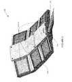
- FIG. 2is a perspective view of a LED sign lighter, according to one exemplary embodiment of the present invention.
- FIG. 3is a perspective view of a LED sign lighter with its center housing cover removed, according to one exemplary embodiment of the present invention.
- FIG. 4is a rear side perspective view of a LED sign lighter, according to one exemplary embodiment of the present invention.
- FIG. 5is a top plan view of a LED sign lighter, according to one exemplary embodiment of the present invention.
- FIG. 6is a bottom plan view of a LED sign lighter, according to one exemplary embodiment of the present invention.
- FIG. 7is a left side elevation view of a LED sign lighter, according to one exemplary embodiment of the present invention.
- FIG. 8is a right side elevation view of a LED sign lighter, according to an exemplary embodiment of the present invention.
- FIG. 9is an exploded view of a LED module for use within the LED sign lighter of FIGS. 2-8 , according to an exemplary embodiment of the present invention.
- FIG. 10is a front side elevation view of a LED sign lighter, according to an exemplary embodiment of the present invention.
- the exemplary LED sign lighter described hereinprovides an efficient, reliable, and long-lasting light source for illuminating signs, such as billboards and overhead roadway directional signs.
- the LED sign lighteroperates more efficiently than conventional sign lighters, and provides a light source that is not subject to striation and excessive light spill, which are common problems associated with conventional sign lighters, such as those that rely on metal halide lamps.
- the LED sign lighterincludes a housing to which all the various components of the LED sign lighter are affixed or positioned therein.
- the position and angle settings for mounting the LED light modules in the housingare pre-set and pre-fabricated so as to require no setting of angles for the discrete LED lighting modules by an installer of the unit, thus reducing human errors commonly associated with poorly aiming the light source.
- the LED sign lighter housingis preferably fabricated as a single diecast piece; however, those or ordinary skill in the art will recognize that the housing may be molded or otherwise manufactured with multiple discrete parts that together create a substantially similar housing.
- each LED moduleis affixed to the housing and oriented outward and/or downward such as to prevent snow, sleet, ice, and rain from accumulating on the housing and hindering the performance of the LEDs.
- each LED moduleincludes an array of LEDs having reflectors or overoptics provided therewith to adjust the angle of the light being emitted from each LED individually and/or multiple LEDs together on the LED module.
- the exemplary LED modulealso includes a plastic or glass cover for protecting the LED array from the elements.
- the housing for the LED sign lighterfurther includes a heat sink built into the diecast housing to provide thermal relief for the LED modules.
- the back portion of the housingincludes cooling fins or ribbons located approximately underneath each LED module.
- FIG. 1is an illustration of a conventional sign lighter 100 .
- a conventional light 100includes a lighting housing 105 affixed to the end of a light holder 110 .
- the housing 105includes a single lamp 115 , such as a halogen or metal halide lamp.
- a light reflector or director 120is also typically included to direct the light upwards and outwards towards the sign.
- this type of conventional lighthas little to no control over the spread of light, and will accordingly typically produce light spill in excess of the dimensions of the sign.
- conventional sign lightersuse filament-type lamps, striations and shadowing are commonly associated with the sign lighter 100 shown in FIG. 1 .
- FIG. 2illustrates a LED sign lighter 200 , according to an exemplary embodiment of the present invention.
- the LED sign lighter 200includes a diecast housing 205 , one or more LED modules 210 A-F, and a compartment cover 215 to protect electrical components (not shown) from weather.
- the LED sign lighter 200includes six LED modules 210 A-F; however, greater or fewer numbers of LED modules 210 may be used based on the design needs of a specific application.
- each of these LED modules 210 A-Fis aimed in a different direction so as to illuminate different portions of a sign of any number of sizes.
- FIG. 2illustrates a LED sign lighter 200 , according to an exemplary embodiment of the present invention.
- the LED sign lighter 200includes a diecast housing 205 , one or more LED modules 210 A-F, and a compartment cover 215 to protect electrical components (not shown) from weather.
- the LED sign lighter 200includes six LED modules 210 A-F; however, greater or fewer numbers of LED modules 210 may be used
- the housing 205is configured to receive and be coupled to a conventional light holder 110 .
- the light holder 110is a metal tube or cylindrical bar that extends outward in a substantially orthogonal direction from the sign being illuminated or the structure holding the sign being illuminated.
- the LED sign lighter housing 205is capable of being coupled to existing signs in a retrofit application that replaces conventional sign lighters.
- FIG. 3is another perspective view of the exemplary LED sign lighter 200 showing the internal electrical components under the compartment cover 215 according to one exemplary embodiment of the present invention.
- the housing 205includes one or more recessed center compartments 305 positioned between at least two sets of LED modules 210 A-F.
- Each center compartment 305is configured to accept electrical components (not shown), such as one or more LED drivers, timers, and/or photocells and associated wiring, within the center compartment 305 .
- electrical componentsprovide proper power and operating parameters for the LED modules 210 A-F used in the housing 205 .
- power to at least six LED modulesis provided by a Class 1 LED driver outputting roughly 150 watts of power.
- a Class 1 LED driveris preferable, it is noted that the exemplary embodiment is not limited to the use of this specific type of LED driver or electrical power source. In another exemplary embodiment, two Class 2 LED drivers rated up to 100 watts and 60 volts are used to power the LED modules 210 A-F. Further, the compartment 305 in the center of the housing 205 is capable of being modified and configured to accommodate any number of LED drivers based on the design needs, the number of LED modules 210 A-F being disposed on the housing 205 , and/or according to the specific requirements of the customer. Wiring of the LED drivers to the individual LEDs or LED modules (as the case may be) is well known in the art and for the sake of brevity will not be described herein.
- FIG. 4illustrates a perspective rear view of the exemplary LED sign lighter 200 .
- the LED sign lighter 200also includes cooling fins 405 extending along the back side of the housing 205 and in thermal communication with the LED modules 210 A-F. While the exemplary embodiment of FIG. 4 shows the heat sink fins 405 being linear, extending along the longitudinal axis of the housing and spaced in a substantially equal manner, in alternative embodiments the fins 405 extend horizontally across the housing 205 , radiate outward from a center point or multiple center points along the back of the housing 205 , are curved or include a combination of curved portions and straight portions, and/or the spacing between each heat sink fin 405 is not equal.
- each heat sink fin 405is molded into the back of the LED sign lighter housing 205 and approximately located under one or more LED modules 205 (not shown in FIG. 4 ). By positioning the heat sink fins 405 directly underneath the LED modules 205 , the contact area between the heat sink and the LED modules 205 is maximized thereby providing for maximum thermal efficiency for operation of the LED sign lighter 200 .
- FIG. 5illustrates a top plan view of the exemplary LED sign lighter 200 .
- six LED modules 210 A-Fare placed on and affixed to six corresponding platforms 515 A-F.
- each LED module 210 A-Fis affixed to its corresponding platform 515 A-F with one of fasteners, arctic silver, solder joints, plugs, epoxy, bonding lines or double-sided heat tape.
- fastenersinclude, but are not limited to, screws, nails, bolts, rivets, a cam-lock switch, a pushbutton plunger, or other device known to those of ordinary skill in the art having the benefit of this disclosure.
- each platform 515 A-Fis in direct thermal contact with the heat sink in general and one or more of the heat sink fins 405 particularly, to efficiently transfer heat from the LED module 210 A-F, through the platform 515 A-F, to the heat sink fins 405 , and to the surrounding environment by way of convection.
- each platform 515 A-Fis a substantially flat planar surface that is disposed at an angle from the longitudinal axis of the sign lighter 200 .
- each of the platformshas at least a partially downward angle from the center of the sign lighter 200 to the outer edge of the platform 515 A-F to channel water from the center of the fixture to the outer edges of the platforms 515 A-F and off of the sign lighter 200 .
- the angle of disposition from the longitudinal axisis different for each platform 515 A-F.
- the different anglesare selected based on a configuration that will direct the light being emitted by the particular LED module 210 A-F on the platform 515 A-F so that each module 210 A-F substantially illuminates a different portion of the sign.
- the sign lighter 200includes the six platforms 515 A-F and the six LED modules 210 A-F disposed correspondingly thereon, the top LED modules 210 A-B are oriented toward the bottom of the sign; the middle LED modules 210 C-D are oriented toward the middle of the sign; and the bottom LED modules 210 E-F are oriented toward the top of the sign.
- the exemplary LED modules 210 A-Finclude one or more LEDs (as described more fully below in relation to FIG. 9 ) and have a substantially square shape that matches or substantially matches the corresponding shape of the individual platforms 515 A-F.
- any size and shape LED module 210 and corresponding platform 515may be used.
- the number of LEDs used in each LED module 210is variable based on the amount of lumens per watt that is achievable from each LED, the number of platforms 515 and modules 210 and the particular design specifics for the particular use of the sign lighter 200 . Accordingly, LED modules 210 having varying numbers of discreet LEDs is within the spirit and scope of the present invention.
- the electrical component cover 215also includes one or more latches 505 A-B and one or more hinges 220 ( FIG. 2 ) to releasably secure the electrical component cover 215 to the LED housing 200 and to rotatably open the cover 215 about the hinges 220 to provide access to the electrical compartment 305 .
- FIG. 6illustrates a bottom plan view of the exemplary LED sign lighter 200 .
- the conventional sign holder 110is inserted into a slot 605 on the housing 205 , which is located on the bottom of the housing 205 , thus allowing the LED sign lighter 200 to be used as a replacement for conventional sign lighters 200 by removing the conventional sign lighter 100 from the sign holder 110 and replacing it with the LED sign lighter 200 by coupling the LED sign lighter to the sign holder 110 .
- the conventional sign holder 110is coupled to a portion of the housing 205 inside the center compartment 305 (not shown) through the use of bolts or other fasteners.
- FIG. 7illustrates a left side elevation view of the exemplary LED sign lighter 200 .
- each LED module 210is set at varying and increasing angles from the horizontal plane X, so as to point at various portions of a sign being illuminated (not shown).
- the LED modules 210 A-Fare angled based on the pre-set angles of the housing 205 .
- the LED modules 210 A-Fare sloped downward from the center section of the housing and gradually increase in angle from top to bottom of the housing as oriented from the horizontal plane X. While the illustrated slopes and angles are not limiting, they are preferably oriented such that the light is evenly distributed across the sign. Additionally, the gradual slope of the LED modules 210 A- 5 is provided to help prevent elements, such as rain and snow, from accumulating on the top of the LED modules 210 A-F when in use.
- FIG. 8illustrates a right side elevation view of the exemplary LED sign lighter 200 .
- one or more LED modules 210 A-Fare sloped downward and upwards in relation to a horizontal plane X.
- the LED sign lighteris preferably symmetrical so that both sides of a sign are illuminated consistently. Therefore, the configuration for the left and right sides of the LED sign lighter 200 mirror one another in a preferred, yet exemplary, embodiment.
- FIG. 9is an exploded view of an LED module 210 for the exemplary LED sign lighter 200 according to one exemplary embodiment of the present invention.
- a substrate 905is configured to fit on to a platform 515 that is part of the LED sign lighter housing 205 by a fastener 915 .
- the substrate 905is mounted to the platform 515 by one or more solder joints, plugs, epoxy or bonding lines, and/or other means for mounting an electrical/optical device on a surface.
- the substrate 905can be mounted to the platform 515 by a two-part arctic silver epoxy or double-sided heat tape.
- the substrate 905includes one or more sheets of ceramic, metal, laminate, circuit board, mylar, or other material.
- the substrate 905accomodates one or more LEDs 925 A-n.
- the LEDs 925are attached to the substrate 905 by one or more solder joints, plugs, epoxy or bonding lines, and/or other means for mounting an electrical/optical device on a surface.
- Each of the LEDs 925includes a chip of semi-conductive material that is treated to create a positive-negative (“p-n”) junction.
- p-npositive-negative
- the wavelength or color of the light emitted from the LEDs 925depends on the materials used to make the LEDs 925 .
- a blue or ultraviolet LEDcan include gallium nitride (“GaN”) or indium gallium nitride (“InGaN”)
- a red LEDcan include aluminum gallium arsenide (“AlGaAs”)
- a green LEDcan include aluminum gallium phosphide (“AlGaP”).
- Each of the LEDs 925can produce the same or a distinct color of light.
- the LEDs 925can include one or more white LED's and one or more non-white LEDs, such as red, yellow, amber, or blue LEDs, for adjusting the color temperature output of the light emitted from the sign lighter 200 .
- a yellow or multi-chromatic phosphormay coat or otherwise be used in a blue or ultraviolet LED to create blue and red-shifted light that essentially matches blackbody radiation.
- the emitted lightapproximates or emulates “white,” incandescent light to a human observer.
- the emitted lightincludes substantially white light that seems slightly blue, green, red, yellow, orange, or some other color or tint.
- the light emitted from the LEDs 925has a color temperature between 2500 and 5000 degrees Kelvin.
- the LEDs 925are an LED package that includes multiple LEDs mounted to the common substrate 905 .
- a reflector 930 for directing and focusing the light emitted by the LEDs 925is disposed above and typically around the perimeter of each of the LEDs 925 (or the LED package as a whole).
- the reflector 930is made of aluminum or has a highly reflective surface to reflect the light generated by the LEDs 925 with minimal loss of efficiency.
- the reflectors 930 for each of the individual LEDs 925 (or LED packages)are molded into a one or more reflector assemblies (as shown in FIG. 9 ); however, the use of individual, discrete reflectors for the LEDs 925 (or LED packages) is also contemplated within the scope of the exemplary embodiments.
- a seal 940is disposed along the top surface of the reflector assembly 930 and about its perimeter and the perimeter of the substrate 905 to protect the substrate 905 and the LEDs 925 from contamination from environmental elements.
- the seal 940is one or many gasket materials know to those of or ordinary skill in the art.
- a translucent material (e.g., glass, lexan, acrylic or other clear or substantially clear material) 945is positioned over the substrate 905 , LEDs 925 , reflector assembly 930 , and the gasket 940 and allows light generated by the LEDs 925 to pass therethrough.
- a frame 950is coupled to the housing 205 with one or more fasteners 955 A-n, such as screws, bolts, rivets, cam-locks and the like, to hold the LED module 210 components together within the housing 205 on its respective platform 515 .
- the glass cover 945could be replaced with a plastic cover under certain configurations.
- over-opticsmay be used in place of the reflector 930 or the cover 945 to control the angle and direction of the light emitted from the LED module 210 .
- FIG. 10illustrates a front view of a LED sign lighter 200 , according to an exemplary embodiment of the present invention.
- the sign lighter 200replaces conventional sign lights by using the mountable clasp 1005 on the bottom of the housing 205 .
- the LED sign lighter 200is then mounted on the end of a conventional sign holder 110 ( FIG. 2 ).
- the LED sign lighter 200is pre-fabricated to optimally light signs of varying sizes.
- the angles of the platforms 515 A-B and the LED modules 210 A-B that are disposed thereonare pointed such that they face the bottom of the sign, and these LED modules 205 A-B preferably spread the light emitted in a wider angle than the other LED modules 205 C-F.
- platforms 515 C-D and LED modules 205 C-D that are disposed thereonare directed toward the middle portion of the sign, and platforms 515 E-F and LED modules 205 E-F that are disposed thereon are directed toward the top portion of the sign.
- the bottom LED modules 205 E-Fhave the narrowest angle reflectors or over-optics, so as to efficiently direct light to the very top portion of the sign without excessive spill.
- the middle modules 205 C-Dhave wider angle reflectors or overoptics than the bottom LED modules 205 E-F, but have narrower reflectors or over-optics when compared to the reflectors or over-optics used in the top LED modules 205 A-B.
- Each LED module 205 A-Fis quickly removable from the housing 205 with the use of simple hand tools, such as a screw driver, so that each individual module 205 may be quickly replaced. Additionally, each LED module 205 is preferably in series with one another so that a malfunctioning LED module 205 A-F will not affect other LED modules used to illuminate the sign.
Landscapes
- Engineering & Computer Science (AREA)
- Physics & Mathematics (AREA)
- General Physics & Mathematics (AREA)
- Theoretical Computer Science (AREA)
- General Engineering & Computer Science (AREA)
- Illuminated Signs And Luminous Advertising (AREA)
- Road Signs Or Road Markings (AREA)
- Non-Portable Lighting Devices Or Systems Thereof (AREA)
Abstract
Description
Claims (15)
Priority Applications (2)
| Application Number | Priority Date | Filing Date | Title |
|---|---|---|---|
| US12/721,204US8408737B2 (en) | 2010-03-10 | 2010-03-10 | Light emitting diode sign lighter |
| PCT/US2010/046326WO2011112210A1 (en) | 2010-03-10 | 2010-08-23 | Light emitting diode sign lighter |
Applications Claiming Priority (1)
| Application Number | Priority Date | Filing Date | Title |
|---|---|---|---|
| US12/721,204US8408737B2 (en) | 2010-03-10 | 2010-03-10 | Light emitting diode sign lighter |
Publications (2)
| Publication Number | Publication Date |
|---|---|
| US20110219650A1 US20110219650A1 (en) | 2011-09-15 |
| US8408737B2true US8408737B2 (en) | 2013-04-02 |
Family
ID=44558561
Family Applications (1)
| Application Number | Title | Priority Date | Filing Date |
|---|---|---|---|
| US12/721,204Active2031-07-17US8408737B2 (en) | 2010-03-10 | 2010-03-10 | Light emitting diode sign lighter |
Country Status (2)
| Country | Link |
|---|---|
| US (1) | US8408737B2 (en) |
| WO (1) | WO2011112210A1 (en) |
Cited By (35)
| Publication number | Priority date | Publication date | Assignee | Title |
|---|---|---|---|---|
| US20130039047A1 (en)* | 2011-08-12 | 2013-02-14 | Kyunghyun Kim | Lighting apparatus |
| US20130056767A1 (en)* | 2010-01-18 | 2013-03-07 | Panasonic Corporation | Led unit |
| USD698479S1 (en)* | 2012-09-10 | 2014-01-28 | Photoquip India Ltd. | Street light |
| US20140355302A1 (en)* | 2013-03-15 | 2014-12-04 | Cree, Inc. | Outdoor and/or Enclosed Structure LED Luminaire for General Illumination Applications, Such as Parking Lots and Structures |
| US9291320B2 (en) | 2013-01-30 | 2016-03-22 | Cree, Inc. | Consolidated troffer |
| US9366799B2 (en) | 2013-03-15 | 2016-06-14 | Cree, Inc. | Optical waveguide bodies and luminaires utilizing same |
| US9366396B2 (en) | 2013-01-30 | 2016-06-14 | Cree, Inc. | Optical waveguide and lamp including same |
| US9389367B2 (en) | 2013-01-30 | 2016-07-12 | Cree, Inc. | Optical waveguide and luminaire incorporating same |
| US9411086B2 (en) | 2013-01-30 | 2016-08-09 | Cree, Inc. | Optical waveguide assembly and light engine including same |
| US9442243B2 (en) | 2013-01-30 | 2016-09-13 | Cree, Inc. | Waveguide bodies including redirection features and methods of producing same |
| US9542870B2 (en) | 2012-07-30 | 2017-01-10 | Ultravision Technologies, Llc | Billboard and lighting assembly with heat sink and three-part lens |
| US9568662B2 (en) | 2013-03-15 | 2017-02-14 | Cree, Inc. | Optical waveguide body |
| US9625638B2 (en) | 2013-03-15 | 2017-04-18 | Cree, Inc. | Optical waveguide body |
| US9645303B2 (en) | 2013-03-15 | 2017-05-09 | Cree, Inc. | Luminaires utilizing edge coupling |
| US9690029B2 (en) | 2013-01-30 | 2017-06-27 | Cree, Inc. | Optical waveguides and luminaires incorporating same |
| US9709725B2 (en) | 2013-03-15 | 2017-07-18 | Cree, Inc. | Luminaire utilizing waveguide |
| US9798072B2 (en) | 2013-03-15 | 2017-10-24 | Cree, Inc. | Optical element and method of forming an optical element |
| US9835317B2 (en) | 2014-03-15 | 2017-12-05 | Cree, Inc. | Luminaire utilizing waveguide |
| US9869432B2 (en) | 2013-01-30 | 2018-01-16 | Cree, Inc. | Luminaires using waveguide bodies and optical elements |
| US9920901B2 (en) | 2013-03-15 | 2018-03-20 | Cree, Inc. | LED lensing arrangement |
| US9952372B2 (en) | 2013-03-15 | 2018-04-24 | Cree, Inc. | Luminaire utilizing waveguide |
| US10209429B2 (en) | 2013-03-15 | 2019-02-19 | Cree, Inc. | Luminaire with selectable luminous intensity pattern |
| US10317608B2 (en) | 2014-03-15 | 2019-06-11 | Cree, Inc. | Luminaires utilizing optical waveguide |
| US10416377B2 (en) | 2016-05-06 | 2019-09-17 | Cree, Inc. | Luminaire with controllable light emission |
| US10422944B2 (en) | 2013-01-30 | 2019-09-24 | Ideal Industries Lighting Llc | Multi-stage optical waveguide for a luminaire |
| US10436970B2 (en) | 2013-03-15 | 2019-10-08 | Ideal Industries Lighting Llc | Shaped optical waveguide bodies |
| US10502899B2 (en)* | 2013-03-15 | 2019-12-10 | Ideal Industries Lighting Llc | Outdoor and/or enclosed structure LED luminaire |
| US10741107B2 (en) | 2013-12-31 | 2020-08-11 | Ultravision Technologies, Llc | Modular display panel |
| US10935211B2 (en) | 2014-05-30 | 2021-03-02 | Ideal Industries Lighting Llc | LED luminaire with a smooth outer dome and a cavity with a ridged inner surface |
| US11112083B2 (en) | 2013-03-15 | 2021-09-07 | Ideal Industries Lighting Llc | Optic member for an LED light fixture |
| AU2017201326B2 (en)* | 2016-03-01 | 2022-04-21 | Braums Pty Ltd | Joint component for a traffic lantern housing |
| US11408572B2 (en) | 2014-03-15 | 2022-08-09 | Ideal Industries Lighting Llc | Luminaires utilizing optical waveguide |
| US20230161127A1 (en)* | 2020-04-15 | 2023-05-25 | CommScope Connectivity Belgium BV | Device and method for sealing cables in telecommunications enclosures |
| US11719882B2 (en) | 2016-05-06 | 2023-08-08 | Ideal Industries Lighting Llc | Waveguide-based light sources with dynamic beam shaping |
| US12372219B2 (en)* | 2014-05-30 | 2025-07-29 | Cree Lighting Usa Llc | LED luminaire with a cavity, finned interior, and a curved outer wall extending from a surface on which the light source is mounted |
Families Citing this family (24)
| Publication number | Priority date | Publication date | Assignee | Title |
|---|---|---|---|---|
| US20110031887A1 (en)* | 2009-05-28 | 2011-02-10 | Stoll Arnold | Led lighting system |
| US8610357B2 (en) | 2009-05-28 | 2013-12-17 | Zon Led, Llc | LED assembly for a signage illumination |
| CN102032471A (en)* | 2009-09-25 | 2011-04-27 | 富准精密工业(深圳)有限公司 | Lamp |
| TWI444563B (en)* | 2010-06-11 | 2014-07-11 | Lite On Technology Corp | LED street light |
| US9028096B2 (en)* | 2011-10-05 | 2015-05-12 | Dialight Corporation | Angled street light fixture |
| US20130135861A1 (en)* | 2011-11-24 | 2013-05-30 | Foxsemicon Integrated Technology, Inc. | Led illuminating device |
| CN103311418B (en)* | 2012-03-06 | 2017-05-24 | 展晶科技(深圳)有限公司 | Light emitting diode module |
| US9062873B2 (en)* | 2012-07-30 | 2015-06-23 | Ultravision Technologies, Llc | Structure for protecting LED light source from moisture |
| US9852666B2 (en) | 2013-03-16 | 2017-12-26 | Adti Media Llc | Full height sectional sign assembly and installation kit and method of using same |
| US9761157B2 (en) | 2013-03-16 | 2017-09-12 | Adti Media Llc | Customized sectional sign assembly kit and method of using kit for construction and installation of same |
| US10210778B2 (en) | 2013-03-16 | 2019-02-19 | Adti Media Llc | Sign construction with sectional sign assemblies and installation kit and method of using same |
| US9047791B2 (en) | 2013-03-16 | 2015-06-02 | Adti Media, Llc. | Sign construction with sectional sign assemblies and installation kit and method of using same |
| US8929083B2 (en) | 2013-03-16 | 2015-01-06 | ADIT Media, LLC | Compound structural frame and method of using same for efficient retrofitting |
| US8824125B1 (en) | 2013-03-16 | 2014-09-02 | ADTI Media, LLC | Modular installation and conversion kit for electronic sign structure and method of using same |
| WO2014186290A2 (en)* | 2013-05-15 | 2014-11-20 | Innovative Electronic Solutions Lighting, Llc | Led light fixtures for billboards |
| US9544973B2 (en) | 2013-12-09 | 2017-01-10 | Kenall Manufacturing Company | Systems and methods for improved lighting systems |
| US20150187237A1 (en) | 2013-12-31 | 2015-07-02 | Ultravision Holdings, Llc | System and Method for a Modular Multi-Panel Display |
| US9582237B2 (en) | 2013-12-31 | 2017-02-28 | Ultravision Technologies, Llc | Modular display panels with different pitches |
| US9719674B2 (en)* | 2014-03-13 | 2017-08-01 | Alled Llc | LED lighting platform |
| US9311847B2 (en) | 2014-07-16 | 2016-04-12 | Ultravision Technologies, Llc | Display system having monitoring circuit and methods thereof |
| CN104832820B (en)* | 2015-05-25 | 2017-10-24 | 刘骁洋 | LED wax tailings steeps comprehensive refraction lamp socket |
| US10690301B2 (en)* | 2016-04-22 | 2020-06-23 | Hubbell Incorporated | Lighting fixture |
| KR102567522B1 (en)* | 2018-07-19 | 2023-08-17 | 삼성전자주식회사 | Display apparatus and manufacturing method thereof |
| US11339933B2 (en)* | 2019-11-06 | 2022-05-24 | Open Platform Systems Llc | Universal LED fixture mount kit |
Citations (23)
| Publication number | Priority date | Publication date | Assignee | Title |
|---|---|---|---|---|
| US2715449A (en) | 1949-12-12 | 1955-08-16 | Carl W Lemmerman | Combined lighting and sound absorbing fixture |
| USD401001S (en) | 1997-07-09 | 1998-11-10 | Peerless Lighting Corporation | Direct-indirect luminaire housing |
| US6250774B1 (en) | 1997-01-23 | 2001-06-26 | U.S. Philips Corp. | Luminaire |
| US20070183148A1 (en) | 2004-06-18 | 2007-08-09 | Mayfield John T Iii | Light fixture |
| USD556935S1 (en) | 2005-10-27 | 2007-12-04 | Hubbell Incorporated | Lighting fixture |
| US20080186703A1 (en)* | 2007-02-06 | 2008-08-07 | Ningbo Andy Optoelectronic Co., Ltd. | High power light emitting diode (led) illumination apparatus |
| USD576330S1 (en) | 2006-09-29 | 2008-09-02 | Ruud Lighting, Inc. | LED floodlight |
| US20080212329A1 (en) | 2004-12-07 | 2008-09-04 | Louis Duguay | Assembly of Light Emitting Diodes for Lighting Applications |
| US7513639B2 (en) | 2006-09-29 | 2009-04-07 | Pyroswift Holding Co., Limited | LED illumination apparatus |
| KR20090043215A (en) | 2007-10-29 | 2009-05-06 | 주식회사 웰라이트 | Street lighting equipment |
| US20090141494A1 (en)* | 2007-11-30 | 2009-06-04 | Fu Zhun Precision Industry (Shen Zhen) Co., Ltd. | Led lamp |
| US20090168422A1 (en) | 2007-12-28 | 2009-07-02 | Foxsemicon Integrated Technology, Inc. | Illumination device |
| US20090244894A1 (en) | 2008-03-26 | 2009-10-01 | Fu Zhun Precision Industry (Shen Zhen) Co., Ltd. | Led assembly for led lamp consisting of multiple led units each having a heat sink |
| US20090251898A1 (en) | 2008-04-04 | 2009-10-08 | Ruud Lighting, Inc. | LED Light Fixture |
| USD603077S1 (en) | 2008-04-04 | 2009-10-27 | Ruud Lighting, Inc. | Lighting fixture |
| USD607598S1 (en) | 2008-12-18 | 2010-01-05 | Foxconn Technology Co., Ltd. | LED lamp |
| KR100942000B1 (en) | 2009-09-11 | 2010-02-12 | (주)이지스테크 | Led illumination apparatus |
| US7665862B2 (en) | 2006-09-12 | 2010-02-23 | Cree, Inc. | LED lighting fixture |
| US20100149809A1 (en) | 2006-09-30 | 2010-06-17 | Ruud Lighting, Inc. | Led lighting fixture |
| USD619749S1 (en) | 2009-08-27 | 2010-07-13 | Jenn Feng New Energy Co., Ltd. | Street light |
| USD632416S1 (en) | 2010-03-10 | 2011-02-08 | Cooper Technologies Company | Luminaire |
| US20110063832A1 (en)* | 2009-09-14 | 2011-03-17 | Leotek Electronics Corporation | Illumination device |
| US20110133670A1 (en)* | 2009-12-04 | 2011-06-09 | Qbas Tech. Co., Ltd. | Street lamp capable of adjusting illuminating range thereof and having LEDs as light source |
Family Cites Families (1)
| Publication number | Priority date | Publication date | Assignee | Title |
|---|---|---|---|---|
| US751639A (en)* | 1904-02-09 | John tv |
- 2010
- 2010-03-10USUS12/721,204patent/US8408737B2/enactiveActive
- 2010-08-23WOPCT/US2010/046326patent/WO2011112210A1/enactiveApplication Filing
Patent Citations (23)
| Publication number | Priority date | Publication date | Assignee | Title |
|---|---|---|---|---|
| US2715449A (en) | 1949-12-12 | 1955-08-16 | Carl W Lemmerman | Combined lighting and sound absorbing fixture |
| US6250774B1 (en) | 1997-01-23 | 2001-06-26 | U.S. Philips Corp. | Luminaire |
| USD401001S (en) | 1997-07-09 | 1998-11-10 | Peerless Lighting Corporation | Direct-indirect luminaire housing |
| US20070183148A1 (en) | 2004-06-18 | 2007-08-09 | Mayfield John T Iii | Light fixture |
| US20080212329A1 (en) | 2004-12-07 | 2008-09-04 | Louis Duguay | Assembly of Light Emitting Diodes for Lighting Applications |
| USD556935S1 (en) | 2005-10-27 | 2007-12-04 | Hubbell Incorporated | Lighting fixture |
| US7665862B2 (en) | 2006-09-12 | 2010-02-23 | Cree, Inc. | LED lighting fixture |
| USD576330S1 (en) | 2006-09-29 | 2008-09-02 | Ruud Lighting, Inc. | LED floodlight |
| US7513639B2 (en) | 2006-09-29 | 2009-04-07 | Pyroswift Holding Co., Limited | LED illumination apparatus |
| US20100149809A1 (en) | 2006-09-30 | 2010-06-17 | Ruud Lighting, Inc. | Led lighting fixture |
| US20080186703A1 (en)* | 2007-02-06 | 2008-08-07 | Ningbo Andy Optoelectronic Co., Ltd. | High power light emitting diode (led) illumination apparatus |
| KR20090043215A (en) | 2007-10-29 | 2009-05-06 | 주식회사 웰라이트 | Street lighting equipment |
| US20090141494A1 (en)* | 2007-11-30 | 2009-06-04 | Fu Zhun Precision Industry (Shen Zhen) Co., Ltd. | Led lamp |
| US20090168422A1 (en) | 2007-12-28 | 2009-07-02 | Foxsemicon Integrated Technology, Inc. | Illumination device |
| US20090244894A1 (en) | 2008-03-26 | 2009-10-01 | Fu Zhun Precision Industry (Shen Zhen) Co., Ltd. | Led assembly for led lamp consisting of multiple led units each having a heat sink |
| US20090251898A1 (en) | 2008-04-04 | 2009-10-08 | Ruud Lighting, Inc. | LED Light Fixture |
| USD603077S1 (en) | 2008-04-04 | 2009-10-27 | Ruud Lighting, Inc. | Lighting fixture |
| USD607598S1 (en) | 2008-12-18 | 2010-01-05 | Foxconn Technology Co., Ltd. | LED lamp |
| USD619749S1 (en) | 2009-08-27 | 2010-07-13 | Jenn Feng New Energy Co., Ltd. | Street light |
| KR100942000B1 (en) | 2009-09-11 | 2010-02-12 | (주)이지스테크 | Led illumination apparatus |
| US20110063832A1 (en)* | 2009-09-14 | 2011-03-17 | Leotek Electronics Corporation | Illumination device |
| US20110133670A1 (en)* | 2009-12-04 | 2011-06-09 | Qbas Tech. Co., Ltd. | Street lamp capable of adjusting illuminating range thereof and having LEDs as light source |
| USD632416S1 (en) | 2010-03-10 | 2011-02-08 | Cooper Technologies Company | Luminaire |
Non-Patent Citations (1)
| Title |
|---|
| International Search Report for PCT/US2010/046326 mailed on Apr. 28, 2011. |
Cited By (62)
| Publication number | Priority date | Publication date | Assignee | Title |
|---|---|---|---|---|
| US9434151B2 (en)* | 2010-01-18 | 2016-09-06 | Panasonic Intellectual Property Management Co., Ltd. | LED unit |
| US20130056767A1 (en)* | 2010-01-18 | 2013-03-07 | Panasonic Corporation | Led unit |
| US20130039047A1 (en)* | 2011-08-12 | 2013-02-14 | Kyunghyun Kim | Lighting apparatus |
| US8827490B2 (en)* | 2011-08-12 | 2014-09-09 | Lg Electronics Inc. | Lighting apparatus |
| US10223946B2 (en) | 2012-07-30 | 2019-03-05 | Ultravision Technologies, Llc | Lighting device with transparent substrate, heat sink and LED array for uniform illumination regardless of number of functional LEDs |
| US9732932B2 (en) | 2012-07-30 | 2017-08-15 | Ultravision Technologies, Llc | Lighting assembly with multiple lighting units |
| US10410551B2 (en) | 2012-07-30 | 2019-09-10 | Ultravision Technologies, Llc | Lighting assembly with LEDs and four-part optical elements |
| US9812043B2 (en) | 2012-07-30 | 2017-11-07 | Ultravision Technologies, Llc | Light assembly for providing substantially uniform illumination |
| US9659511B2 (en) | 2012-07-30 | 2017-05-23 | Ultravision Technologies, Llc | LED light assembly having three-part optical elements |
| US9734737B2 (en) | 2012-07-30 | 2017-08-15 | Ultravision Technologies, Llc | Outdoor billboard with lighting assemblies |
| US10339841B2 (en) | 2012-07-30 | 2019-07-02 | Ultravision Technologies, Llc | Lighting assembly with multiple lighting units |
| US9947248B2 (en) | 2012-07-30 | 2018-04-17 | Ultravision Technologies, Llc | Lighting assembly with multiple lighting units |
| US9734738B2 (en) | 2012-07-30 | 2017-08-15 | Ultravision Technologies, Llc | Apparatus with lighting units |
| US9542870B2 (en) | 2012-07-30 | 2017-01-10 | Ultravision Technologies, Llc | Billboard and lighting assembly with heat sink and three-part lens |
| US10891881B2 (en) | 2012-07-30 | 2021-01-12 | Ultravision Technologies, Llc | Lighting assembly with LEDs and optical elements |
| US10460634B2 (en) | 2012-07-30 | 2019-10-29 | Ultravision Technologies, Llc | LED light assembly with transparent substrate having array of lenses for projecting light to illuminate an area |
| US9685102B1 (en) | 2012-07-30 | 2017-06-20 | Ultravision Technologies, Llc | LED lighting assembly with uniform output independent of number of number of active LEDs, and method |
| USD698479S1 (en)* | 2012-09-10 | 2014-01-28 | Photoquip India Ltd. | Street light |
| US9389367B2 (en) | 2013-01-30 | 2016-07-12 | Cree, Inc. | Optical waveguide and luminaire incorporating same |
| US11099317B2 (en) | 2013-01-30 | 2021-08-24 | Ideal Industries Lighting Llc | Multi-stage optical waveguide for a luminaire |
| US9690029B2 (en) | 2013-01-30 | 2017-06-27 | Cree, Inc. | Optical waveguides and luminaires incorporating same |
| US9581751B2 (en) | 2013-01-30 | 2017-02-28 | Cree, Inc. | Optical waveguide and lamp including same |
| US9519095B2 (en) | 2013-01-30 | 2016-12-13 | Cree, Inc. | Optical waveguides |
| US9442243B2 (en) | 2013-01-30 | 2016-09-13 | Cree, Inc. | Waveguide bodies including redirection features and methods of producing same |
| US9411086B2 (en) | 2013-01-30 | 2016-08-09 | Cree, Inc. | Optical waveguide assembly and light engine including same |
| US10436969B2 (en) | 2013-01-30 | 2019-10-08 | Ideal Industries Lighting Llc | Optical waveguide and luminaire incorporating same |
| US9366396B2 (en) | 2013-01-30 | 2016-06-14 | Cree, Inc. | Optical waveguide and lamp including same |
| US9823408B2 (en) | 2013-01-30 | 2017-11-21 | Cree, Inc. | Optical waveguide and luminaire incorporating same |
| US10422944B2 (en) | 2013-01-30 | 2019-09-24 | Ideal Industries Lighting Llc | Multi-stage optical waveguide for a luminaire |
| US9869432B2 (en) | 2013-01-30 | 2018-01-16 | Cree, Inc. | Luminaires using waveguide bodies and optical elements |
| US11644157B2 (en) | 2013-01-30 | 2023-05-09 | Ideal Industries Lighting Llc | Luminaires using waveguide bodies and optical elements |
| US9291320B2 (en) | 2013-01-30 | 2016-03-22 | Cree, Inc. | Consolidated troffer |
| US11675120B2 (en) | 2013-01-30 | 2023-06-13 | Ideal Industries Lighting Llc | Optical waveguides for light fixtures and luminaires |
| US9568662B2 (en) | 2013-03-15 | 2017-02-14 | Cree, Inc. | Optical waveguide body |
| US9366799B2 (en) | 2013-03-15 | 2016-06-14 | Cree, Inc. | Optical waveguide bodies and luminaires utilizing same |
| US10168467B2 (en) | 2013-03-15 | 2019-01-01 | Cree, Inc. | Luminaires utilizing edge coupling |
| US20140355302A1 (en)* | 2013-03-15 | 2014-12-04 | Cree, Inc. | Outdoor and/or Enclosed Structure LED Luminaire for General Illumination Applications, Such as Parking Lots and Structures |
| US9952372B2 (en) | 2013-03-15 | 2018-04-24 | Cree, Inc. | Luminaire utilizing waveguide |
| US10379278B2 (en)* | 2013-03-15 | 2019-08-13 | Ideal Industries Lighting Llc | Outdoor and/or enclosed structure LED luminaire outdoor and/or enclosed structure LED luminaire having outward illumination |
| US9920901B2 (en) | 2013-03-15 | 2018-03-20 | Cree, Inc. | LED lensing arrangement |
| US9625638B2 (en) | 2013-03-15 | 2017-04-18 | Cree, Inc. | Optical waveguide body |
| US10209429B2 (en) | 2013-03-15 | 2019-02-19 | Cree, Inc. | Luminaire with selectable luminous intensity pattern |
| US9798072B2 (en) | 2013-03-15 | 2017-10-24 | Cree, Inc. | Optical element and method of forming an optical element |
| US10436970B2 (en) | 2013-03-15 | 2019-10-08 | Ideal Industries Lighting Llc | Shaped optical waveguide bodies |
| US9709725B2 (en) | 2013-03-15 | 2017-07-18 | Cree, Inc. | Luminaire utilizing waveguide |
| US10502899B2 (en)* | 2013-03-15 | 2019-12-10 | Ideal Industries Lighting Llc | Outdoor and/or enclosed structure LED luminaire |
| US11112083B2 (en) | 2013-03-15 | 2021-09-07 | Ideal Industries Lighting Llc | Optic member for an LED light fixture |
| US9645303B2 (en) | 2013-03-15 | 2017-05-09 | Cree, Inc. | Luminaires utilizing edge coupling |
| US10741107B2 (en) | 2013-12-31 | 2020-08-11 | Ultravision Technologies, Llc | Modular display panel |
| US9835317B2 (en) | 2014-03-15 | 2017-12-05 | Cree, Inc. | Luminaire utilizing waveguide |
| US11408572B2 (en) | 2014-03-15 | 2022-08-09 | Ideal Industries Lighting Llc | Luminaires utilizing optical waveguide |
| US10317608B2 (en) | 2014-03-15 | 2019-06-11 | Cree, Inc. | Luminaires utilizing optical waveguide |
| US10935211B2 (en) | 2014-05-30 | 2021-03-02 | Ideal Industries Lighting Llc | LED luminaire with a smooth outer dome and a cavity with a ridged inner surface |
| US12372219B2 (en)* | 2014-05-30 | 2025-07-29 | Cree Lighting Usa Llc | LED luminaire with a cavity, finned interior, and a curved outer wall extending from a surface on which the light source is mounted |
| AU2017201326B2 (en)* | 2016-03-01 | 2022-04-21 | Braums Pty Ltd | Joint component for a traffic lantern housing |
| US10890714B2 (en) | 2016-05-06 | 2021-01-12 | Ideal Industries Lighting Llc | Waveguide-based light sources with dynamic beam shaping |
| US10527785B2 (en) | 2016-05-06 | 2020-01-07 | Ideal Industries Lighting Llc | Waveguide-based light sources with dynamic beam shaping |
| US11372156B2 (en) | 2016-05-06 | 2022-06-28 | Ideal Industries Lighting Llc | Waveguide-based light sources with dynamic beam shaping |
| US10416377B2 (en) | 2016-05-06 | 2019-09-17 | Cree, Inc. | Luminaire with controllable light emission |
| US11719882B2 (en) | 2016-05-06 | 2023-08-08 | Ideal Industries Lighting Llc | Waveguide-based light sources with dynamic beam shaping |
| US12353005B2 (en) | 2016-05-06 | 2025-07-08 | Cree Lighting Usa Llc | Waveguide-based light sources with dynamic beam shaping |
| US20230161127A1 (en)* | 2020-04-15 | 2023-05-25 | CommScope Connectivity Belgium BV | Device and method for sealing cables in telecommunications enclosures |
Also Published As
| Publication number | Publication date |
|---|---|
| WO2011112210A1 (en) | 2011-09-15 |
| US20110219650A1 (en) | 2011-09-15 |
Similar Documents
| Publication | Publication Date | Title |
|---|---|---|
| US8408737B2 (en) | Light emitting diode sign lighter | |
| US8220977B2 (en) | Solid state light unit and heat sink, and method for thermal management of a solid state light unit | |
| US8038314B2 (en) | Light emitting diode troffer | |
| US8783900B2 (en) | LED replacement lamp and a method of replacing preexisting luminaires with LED lighting assemblies | |
| TWI515387B (en) | Street lamp and its illuminating equipment | |
| US8794803B1 (en) | Adjustable LED module with stationary heat sink | |
| US7267461B2 (en) | Directly viewable luminaire | |
| US7874700B2 (en) | Heat management for a light fixture with an adjustable optical distribution | |
| EP2232133B1 (en) | Optoelectronic module and illumination device | |
| US10260730B2 (en) | LED luminaire light fixture for a lamppost | |
| US20120051055A1 (en) | Retrofit system for converting an existing luminaire into a solid state lighting luminaire | |
| KR101034481B1 (en) | Luminaires to prevent frost formation | |
| EP3228930B1 (en) | Heat dissipating reflectors for led luminaires | |
| KR100468257B1 (en) | Flat light fixture using light emitting diode | |
| US10132486B2 (en) | LED lamp with axial directed reflector | |
| KR101879216B1 (en) | Lighting device | |
| KR20090067333A (en) | Street light with LED lamp | |
| KR101823135B1 (en) | Lighting device | |
| KR20160109838A (en) | High-efficiency led lighting device |
Legal Events
| Date | Code | Title | Description |
|---|---|---|---|
| AS | Assignment | Owner name:COOPER TECHNOLOGIES COMPANY, TEXAS Free format text:ASSIGNMENT OF ASSIGNORS INTEREST;ASSIGNORS:WRIGHT, TIMOTHY;RONG, WEI;THORNTON, GERRY;REEL/FRAME:024067/0239 Effective date:20100310 | |
| FEPP | Fee payment procedure | Free format text:PAYOR NUMBER ASSIGNED (ORIGINAL EVENT CODE: ASPN); ENTITY STATUS OF PATENT OWNER: LARGE ENTITY | |
| STCF | Information on status: patent grant | Free format text:PATENTED CASE | |
| FPAY | Fee payment | Year of fee payment:4 | |
| AS | Assignment | Owner name:EATON INTELLIGENT POWER LIMITED, IRELAND Free format text:ASSIGNMENT OF ASSIGNORS INTEREST;ASSIGNOR:COOPER TECHNOLOGIES COMPANY;REEL/FRAME:048207/0819 Effective date:20171231 | |
| AS | Assignment | Owner name:EATON INTELLIGENT POWER LIMITED, IRELAND Free format text:CORRECTIVE ASSIGNMENT TO CORRECT THE COVER SHEET TO REMOVE APPLICATION NO. 15567271 PREVIOUSLY RECORDED ON REEL 048207 FRAME 0819. ASSIGNOR(S) HEREBY CONFIRMS THE ASSIGNMENT;ASSIGNOR:COOPER TECHNOLOGIES COMPANY;REEL/FRAME:048655/0114 Effective date:20171231 | |
| AS | Assignment | Owner name:SIGNIFY HOLDING B.V., NETHERLANDS Free format text:ASSIGNMENT OF ASSIGNORS INTEREST;ASSIGNOR:EATON INTELLIGENT POWER LIMITED;REEL/FRAME:052681/0475 Effective date:20200302 | |
| MAFP | Maintenance fee payment | Free format text:PAYMENT OF MAINTENANCE FEE, 8TH YEAR, LARGE ENTITY (ORIGINAL EVENT CODE: M1552); ENTITY STATUS OF PATENT OWNER: LARGE ENTITY Year of fee payment:8 | |
| AS | Assignment | Owner name:SIGNIFY HOLDING B.V., NETHERLANDS Free format text:CORRECTIVE ASSIGNMENT TO CORRECT THE APPLICATION NUMBERS 12183490, 12183499, 12494944, 12961315, 13528561, 13600790, 13826197, 14605880, 15186648, RECORDED IN ERROR PREVIOUSLY RECORDED ON REEL 052681 FRAME 0475. ASSIGNOR(S) HEREBY CONFIRMS THE ASSIGNMENT;ASSIGNOR:EATON INTELLIGENT POWER LIMITED;REEL/FRAME:055965/0721 Effective date:20200302 | |
| MAFP | Maintenance fee payment | Free format text:PAYMENT OF MAINTENANCE FEE, 12TH YEAR, LARGE ENTITY (ORIGINAL EVENT CODE: M1553); ENTITY STATUS OF PATENT OWNER: LARGE ENTITY Year of fee payment:12 |