US8408287B2 - Electrical jumper for a producing oil well - Google Patents
Electrical jumper for a producing oil wellDownload PDFInfo
- Publication number
- US8408287B2 US8408287B2US12/792,815US79281510AUS8408287B2US 8408287 B2US8408287 B2US 8408287B2US 79281510 AUS79281510 AUS 79281510AUS 8408287 B2US8408287 B2US 8408287B2
- Authority
- US
- United States
- Prior art keywords
- tubing
- tubings
- bore
- electrical
- interconnected
- Prior art date
- Legal status (The legal status is an assumption and is not a legal conclusion. Google has not performed a legal analysis and makes no representation as to the accuracy of the status listed.)
- Active, expires
Links
- 239000003129oil wellSubstances0.000title1
- 230000000153supplemental effectEffects0.000claimsabstractdescription5
- 230000001771impaired effectEffects0.000claimsdescription17
- 230000015572biosynthetic processEffects0.000claimsdescription13
- 239000012530fluidSubstances0.000claimsdescription6
- 239000013536elastomeric materialSubstances0.000claimsdescription2
- 238000003491arrayMethods0.000claims1
- 239000004020conductorSubstances0.000claims1
- 238000003780insertionMethods0.000abstract1
- 230000037431insertionEffects0.000abstract1
- 238000009434installationMethods0.000description7
- 238000004519manufacturing processMethods0.000description3
- 238000005553drillingMethods0.000description2
- 230000002708enhancing effectEffects0.000description2
- 239000011152fibreglassSubstances0.000description2
- 230000000295complement effectEffects0.000description1
- 230000008602contractionEffects0.000description1
- 238000007599dischargingMethods0.000description1
- 230000005684electric fieldEffects0.000description1
- 238000000605extractionMethods0.000description1
- 239000011810insulating materialSubstances0.000description1
- 238000000034methodMethods0.000description1
- 238000012986modificationMethods0.000description1
- 230000004048modificationEffects0.000description1
- 150000002825nitrilesChemical class0.000description1
- 230000000149penetrating effectEffects0.000description1
- 238000003466weldingMethods0.000description1
Images


Classifications
- H—ELECTRICITY
- H01—ELECTRIC ELEMENTS
- H01R—ELECTRICALLY-CONDUCTIVE CONNECTIONS; STRUCTURAL ASSOCIATIONS OF A PLURALITY OF MUTUALLY-INSULATED ELECTRICAL CONNECTING ELEMENTS; COUPLING DEVICES; CURRENT COLLECTORS
- H01R4/00—Electrically-conductive connections between two or more conductive members in direct contact, i.e. touching one another; Means for effecting or maintaining such contact; Electrically-conductive connections having two or more spaced connecting locations for conductors and using contact members penetrating insulation
- H01R4/58—Electrically-conductive connections between two or more conductive members in direct contact, i.e. touching one another; Means for effecting or maintaining such contact; Electrically-conductive connections having two or more spaced connecting locations for conductors and using contact members penetrating insulation characterised by the form or material of the contacting members
- H01R4/64—Connections between or with conductive parts having primarily a non-electric function, e.g. frame, casing, rail
- E—FIXED CONSTRUCTIONS
- E21—EARTH OR ROCK DRILLING; MINING
- E21B—EARTH OR ROCK DRILLING; OBTAINING OIL, GAS, WATER, SOLUBLE OR MELTABLE MATERIALS OR A SLURRY OF MINERALS FROM WELLS
- E21B17/00—Drilling rods or pipes; Flexible drill strings; Kellies; Drill collars; Sucker rods; Cables; Casings; Tubings
- E21B17/003—Drilling rods or pipes; Flexible drill strings; Kellies; Drill collars; Sucker rods; Cables; Casings; Tubings with electrically conducting or insulating means
- E—FIXED CONSTRUCTIONS
- E21—EARTH OR ROCK DRILLING; MINING
- E21B—EARTH OR ROCK DRILLING; OBTAINING OIL, GAS, WATER, SOLUBLE OR MELTABLE MATERIALS OR A SLURRY OF MINERALS FROM WELLS
- E21B43/00—Methods or apparatus for obtaining oil, gas, water, soluble or meltable materials or a slurry of minerals from wells
- E21B43/16—Enhanced recovery methods for obtaining hydrocarbons
- H—ELECTRICITY
- H01—ELECTRIC ELEMENTS
- H01R—ELECTRICALLY-CONDUCTIVE CONNECTIONS; STRUCTURAL ASSOCIATIONS OF A PLURALITY OF MUTUALLY-INSULATED ELECTRICAL CONNECTING ELEMENTS; COUPLING DEVICES; CURRENT COLLECTORS
- H01R13/00—Details of coupling devices of the kinds covered by groups H01R12/70 or H01R24/00 - H01R33/00
- H01R13/02—Contact members
- H01R13/15—Pins, blades or sockets having separate spring member for producing or increasing contact pressure
- H01R13/17—Pins, blades or sockets having separate spring member for producing or increasing contact pressure with spring member on the pin
Definitions
- the present inventionrelates to apparatus for enhancing the production of oil from subterranean oil reservoirs with the aid of electric current and, in particular, apparatus for enhancing the performance of the method described in U.S. Pat. No. 7,325,604, issued Feb. 5, 2008, the entire contents of which are incorporated herein by reference.
- the oil producing wellis completed by drilling a downhole into the oil-bearing formation and providing intercommunicating conduit sections to provide a casing and/or a liner for the removal of oil.
- the lineris foraminous in order to permit the oil to enter the conduit sections throughout the length of the foraminous liner. It has been found that the production of oil is enhanced by connecting a negative electrode to the liner and introducing a second electrode in proximity to the formation. A voltage difference is established between the first and second electrodes to create an electric field across the formation.
- the downholeis drilled and the liner is installed and is connected to a casing which is anchored at the surface above the formation.
- the casingis connected to the proximal end of the liner and is operatively connected to the bore of the liner.
- the casingmounts a pump for the extraction of the oil produced by the well.
- the casing and the linersare formed by a series of interconnected conduit sections which have joints along their lengths between the proximal and distal ends of the drilling hole.
- the conduit sectionsare electrically conductive to provide a path of electrical conductivity along the length of the assembled conduit sections.
- the present inventionprovides an electrical jumper for bridging the impaired joints between the adjacent aligned conduit sections to insure an unimpeded path of electrical conductivity between the conduit sections, reducing the loss of voltage which may occur when the joints deteriorate, and/or when the joints do not otherwise provide adequate electrical conductivity between the adjacent sections.
- the present inventionprovides a jumper composed of interconnected tubings adapted to be centered in the adjacent conduit sections on either side of the joint.
- the tubingshave a central bore which permits the flow of oil from the downhole into the casing where it is withdrawn by the conventional pump which is mounted at the bottom of the casing.
- the oilis pumped to the surface by the pump through piping.
- centering devicesare provided about the outer perimeter of the tubings to center the same within the bores of the conduit sections or liners, the centering devices including means to provide a path of electrical conductivity between the conduit section or liner and the enclosed tubing.
- the centering deviceincludes a pair of rings encircling the tubing.
- the ringsare connected by an array of bowed springs spaced circumferentially about the rings.
- Each bowed springbows outwardly between the rings to resiliently bear against the interior bore of the conduit section in which it is mounted.
- Each ringencircles the outer circumference of the tubing, one of the rings being anchored to the tubing and the other of the rings being free to be displaced longitudinally of the tubing to allow radial expansion and contraction of the bowed springs.
- the inventionmay also insure enhanced electrical conductivity by providing electrical contacts on the bowed springs where they bear against the internal bore of the associated conduit section to enhance the electrical conductivity between the bowed spring and the ring which is electrically connected to the tubing, for example by welding.
- the jumpermay be modified to reduce oil leakage through the joint between the interiors of the conduit sections and the surrounding underground formation.
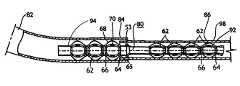
- FIG. 1is a side elevation of an electrical jumper embodying the present invention with an upper quadrant of the jumper broken away;
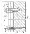
- FIG. 2is a diagrammatic view of a producing well having an upper casing and a lower liner vertically aligned, with a jumper according to FIG. 1 installed between the casing and the liner to provide an unimpeded path of electrical conductivity therebetween;
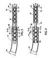
- FIG. 3is a fragmentary view of a producing well installation having a horizontal liner telescopically inserted into the horizontal end of a casing with a jumper having portions respectively inserted into the casing and the liner to establish an unimpeded path of electrical conductivity therebetween (for the purposes of illustration the clearance between the components of the impaired joint has been exaggerated);
- FIG. 4is a fragmentary view of a producing well installation similar to FIG. 3 wherein the telescopic joint is impaired by dislodgment of the horizontal liner to a position adjacent the horizontal end of a casing with the jumper shown in FIG. 3 having portions respectively inserted into the casing and the liner to establish an unimpeded path of electrical conductivity therebetween and with plugs surrounding the opposite ends of the jumper to reduce leakage through the joint between a casing and a liner (for the purposes of illustration, the spacing between the components of the impaired joint has been exaggerated); and
- FIG. 5is an enlarged fragmentary jumper of FIG. 3 which is mounted inside the casing showing its connection to the adjoining distal tubing portion of the jumper which is mounted inside the liner (the tubing being shown in section).
- FIG. 2the drawing illustrates an oil producing well 13 of the type shown in U.S. Pat. No. 7,325,604.
- the well 13has a bore hole penetrating the oil-bearing formation 11 having a foraminous liner 24 which is connected to a casing 18 extending from the surface to the top of the formation 11 by a connecting joint at 49 .
- the liner and casingare metallic and are connected to the negative terminal of an electric voltage source 38 .
- a second bore hole 14penetrates the oil formation 11 and encloses an electrode 15 which is connected to the positive terminal of the voltage source 38 .
- the voltage sourcesupplies an electric signal which has been found to enhance the production of oil from the formation 11 .
- a pump 25is mounted in the casing and has piping 21 for discharging the oil accumulating at the bottom of the casing 18 .
- the casing and the linerconstitute conduit sections which are effective to conduct oil from the oil-bearing formation into the casing where it is extracted by the pump 25 .
- a jumper 50has a first tubing 52 which is hollow and is designed to fit within the distal conduit section shown in FIG.
- tubings 52 and 54are interconnected by a joint or fitting 53 and are adapted to be anchored into the well by an anchor 56 which has a series of jaws 58 which are operable to be displaced radially outward to firmly anchor the jumper within the bore hole.
- the anchorhas at least three jaws equally spaced about its perimeter so as to firmly anchor the jumper into the casing.
- the anchor 56is connected to the tubings 52 and 54 by a fiberglass pup joint 60 of fiberglass or other insulating material which electrically isolates the anchor 56 from the interconnected tubings 52 and 54 .
- the tubingsare centered within their respective conduit sections by bowed leaf springs 68 in centering devices 62 to provide a narrow annular space surrounding each tubing.
- each centering device 60comprises a pair of rings 64 and 66 encircling the tubing.
- One of the rings 64is electrically and mechanically connected to the tubing 54 , for example by a weld joint 65 , whereas the opposite ring 66 is slidable on the underlying tubing.
- the two rings 64 and 66are interconnected by leaf springs 68 which span between the rings and are bowed outwardly to engage the interior wall of the surrounding conduit section.
- the bowed leaf springsare arranged in a circular array about the entire circumference of the centering device 62 and are biased outwardly into firm engagement with the interior wall of the surrounding conduit section.
- the displaceable ring 66may be displaced longitudinally of the tubing to increase or decrease the projection of the outer perimeter of the array of bowed springs 68 , as required by their engagement with the interior surface of the conduit section.
- the medial portions of the leaf spring 68are provided with supplemental electrical contacts 70 which assure electrical contact between the springs and the surrounding conduit section.
- the electrical path between the supplemental contacts 70 and the connected ring 64is through the spring itself, but if desired, an additional electrical path may be provided to assure electrical conductivity from the conduit section through the contact to the ring 64 and the underlying tubing. It has been found desirable to design the jumper so that the bores of the tubings are between 40-55% of the bore of the associated conduit section, leaving room for the centering devices in the annular space surrounding the liners.
- FIGS. 3 and 4show two installations using a modified jumper 80 inserted between a well casing and horizontal liners of the downhole.
- the well casing 82terminates in a horizontal extension 84 which is adapted to be joined with the proximal end of a liner 86 of the downhole.
- the liner 86telescopically engages the open end of the extension 84 , illustrating a clearance which may impair the joint, whereas in FIG. 4 , the joint is impaired because the liner 86 is separated from the extension 84 .
- the jumper 80is provided to provide an unimpeded path of electrical conductivity between the casing 82 and the liner 86 .
- the jumper 80when the jumper is used to bridge the gap in the series of adjacent aligned conduit sections which are spaced apart, it may be desirable to insert an annular plug 102 between the extension 84 and the tubing 94 to close off the annular space between these components. Similarly, the annular space between the liner 86 and the tubing 92 may be plugged by an annular plug 104 to reduce leakage which would otherwise occur as a result of the gap.
- the jumper 80not only provides electrical conductivity between the separated conduit sections, but also prevents leakage between the annular space within the conduit sections and the underground formation surrounding the gap.
- the plugsare annular rings of nitrile or other elastomeric material which is resistant to the fluids carried by the conduit sections.
- the overall length of the jumper 80 shown in FIGS. 3 and 4is shorter than the jumper 50 shown in FIG. 1 , so that the jumper 80 will pass through the curvature between the extension 84 and the upper end of the casing at the surface.
- the casingfollows an arcuate path from the surface to the extension 84 and the length of the jumper is tailored to pass along the arcuate path without jamming.
- the jumper 80is similar to the jumper 50 having distal and proximal tubings 92 and 94 interconnected by a joint or fitting 53 .
- the tubings 92 and 94have centering devices comprising fixed rings 64 and slidable rings interconnected by bowed springs 68 disposed in a circular array between the rings 64 and 66 .
- the bowed springs 68are provided with electrical contacts 70 and 100 similar to the contacts 70 described in connection with FIG. 1 .
- the contactsare designed to provide electrical continuity between the liners 84 and 86 and the fixed rings 64 of the centering devices
- each embodiment of the inventionis designed to complement the conduit sections into which the jumper is installed.
- each tubinghas a bore which is between 40-55% of the bore of the associated conduit section to provide an annular space surrounding the tubings.
- the fitting between the proximal and distal tubingshas an outer diameter smaller than the bore of the conduit sections 84 and 86 surrounding the conduit section so as to allow limited flow between the annular spaces surrounding the distal and proximal tubings.
- the distal conduit section 86is adjacent to, and is longitudinally aligned with the proximal conduit section 84 , and its proximal end is disposed within the terminal end of the proximal conduit section,
- the distal conduit section 86is adjacent to, and is longitudinally aligned with, the proximal conduit section 84 , and its proximal end is disposed spaced from the terminal end of the proximal conduit section.
Landscapes
- Engineering & Computer Science (AREA)
- Life Sciences & Earth Sciences (AREA)
- Geology (AREA)
- Mining & Mineral Resources (AREA)
- Physics & Mathematics (AREA)
- Environmental & Geological Engineering (AREA)
- Fluid Mechanics (AREA)
- General Life Sciences & Earth Sciences (AREA)
- Geochemistry & Mineralogy (AREA)
- Mechanical Engineering (AREA)
- Earth Drilling (AREA)
Abstract
Description
Claims (11)
Priority Applications (2)
| Application Number | Priority Date | Filing Date | Title |
|---|---|---|---|
| US12/792,815US8408287B2 (en) | 2010-06-03 | 2010-06-03 | Electrical jumper for a producing oil well |
| CA2708567ACA2708567C (en) | 2010-06-03 | 2010-06-28 | Electrical jumper for a producing oil well |
Applications Claiming Priority (1)
| Application Number | Priority Date | Filing Date | Title |
|---|---|---|---|
| US12/792,815US8408287B2 (en) | 2010-06-03 | 2010-06-03 | Electrical jumper for a producing oil well |
Publications (2)
| Publication Number | Publication Date |
|---|---|
| US20110297366A1 US20110297366A1 (en) | 2011-12-08 |
| US8408287B2true US8408287B2 (en) | 2013-04-02 |
Family
ID=45063564
Family Applications (1)
| Application Number | Title | Priority Date | Filing Date |
|---|---|---|---|
| US12/792,815Active2031-05-24US8408287B2 (en) | 2010-06-03 | 2010-06-03 | Electrical jumper for a producing oil well |
Country Status (2)
| Country | Link |
|---|---|
| US (1) | US8408287B2 (en) |
| CA (1) | CA2708567C (en) |
Cited By (1)
| Publication number | Priority date | Publication date | Assignee | Title |
|---|---|---|---|---|
| US20180223620A1 (en)* | 2015-08-06 | 2018-08-09 | Ge Oil & Gas Uk Limited | Subsea flying lead |
Families Citing this family (3)
| Publication number | Priority date | Publication date | Assignee | Title |
|---|---|---|---|---|
| US20140174819A1 (en)* | 2012-12-26 | 2014-06-26 | Mehri Mafi | Cable Assembly |
| CN107364409A (en)* | 2017-08-14 | 2017-11-21 | 瑞安市纳德睿电子科技有限公司 | A kind of connection sheet of gasbag coil |
| GB201718255D0 (en) | 2017-11-03 | 2017-12-20 | Expro North Sea Ltd | Deployable devices and methods |
Citations (51)
| Publication number | Priority date | Publication date | Assignee | Title |
|---|---|---|---|---|
| US1773398A (en)* | 1928-03-21 | 1930-08-19 | Velle Mathew A La | Centering device for well casings or liners |
| US2220237A (en)* | 1937-01-06 | 1940-11-05 | Jesse E Hall | Well cleaner |
| US2387493A (en)* | 1943-03-01 | 1945-10-23 | Charles A Brokaw | Means for cementing wells |
| US2555628A (en)* | 1948-03-08 | 1951-06-05 | Baker Oil Tools Inc | Casing centralizer |
| US2562083A (en)* | 1948-10-01 | 1951-07-24 | Baker Oil Tools Inc | Casing centralizer |
| US2832421A (en)* | 1953-11-24 | 1958-04-29 | Baker Oil Tools Inc | Centering apparatus for well bore conduits |
| US2841226A (en)* | 1953-11-24 | 1958-07-01 | Baker Oil Tools Inc | Well bore conduit centering apparatus |
| US2997108A (en)* | 1957-05-24 | 1961-08-22 | Sievers | Well cleaning apparatus |
| US3000444A (en)* | 1957-11-05 | 1961-09-19 | B And W Inc | Centralizer |
| US3044554A (en)* | 1959-02-13 | 1962-07-17 | Kluck Louis | Casing centralizer |
| US3124196A (en)* | 1964-03-10 | Helical bow centralizer | ||
| US3149676A (en)* | 1961-07-20 | 1964-09-22 | A Z Skeeters | Apparatus for testing and replacing defective well casing |
| US3270697A (en)* | 1962-10-02 | 1966-09-06 | B & W Inc | Method for forming a pipe centering device |
| US3437142A (en)* | 1965-10-28 | 1969-04-08 | George E Conover | Inflatable packer for external use on casing and liners and method of use |
| US3542127A (en)* | 1968-05-13 | 1970-11-24 | Lynes Inc | Reinforced inflatable packer with expansible back-up skirts for end portions |
| US3572432A (en)* | 1969-09-25 | 1971-03-23 | Halliburton Co | Apparatus for flotation completion for highly deviated wells |
| US3977468A (en) | 1975-10-28 | 1976-08-31 | Dresser Industries, Inc. | Well bore caliper and centralizer apparatus having articulated linkage |
| US4088186A (en)* | 1976-12-22 | 1978-05-09 | Baker International Corporation | Centering device for well conduit |
| US4363360A (en)* | 1981-01-15 | 1982-12-14 | Richey Vernon T | Apparatus for use in maintaining a well pipe centered within a well bore |
| US4651823A (en)* | 1986-05-19 | 1987-03-24 | Antelope Oil Tool & Mfg. Company | Centralizer |
| US5033549A (en)* | 1989-12-27 | 1991-07-23 | Perf-O-Log, Inc. | Method for placing a gravel pack in an oil well with an electric wireline |
| US5115860A (en)* | 1989-12-27 | 1992-05-26 | Perf-O-Log, Inc | Gravel pack apparatus run with an electric wireline |
| USH1192H (en)* | 1990-10-26 | 1993-06-01 | Exxon Production Research Company | Low-torque centralizer |
| US5261488A (en)* | 1990-01-17 | 1993-11-16 | Weatherford U.K. Limited | Centralizers for oil well casings |
| US5339898A (en)* | 1993-07-13 | 1994-08-23 | Texaco Canada Petroleum, Inc. | Electromagnetic reservoir heating with vertical well supply and horizontal well return electrodes |
| US5377750A (en)* | 1992-07-29 | 1995-01-03 | Halliburton Company | Sand screen completion |
| US5641018A (en)* | 1995-01-12 | 1997-06-24 | King; Harlan R. | Apparatus and method for cementing wells |
| US20020053436A1 (en)* | 2000-04-24 | 2002-05-09 | Vinegar Harold J. | In situ thermal processing of a coal formation to pyrolyze a selected percentage of hydrocarbon material |
| US20020112853A1 (en)* | 2001-02-20 | 2002-08-22 | Buytaert Jean P. | Expandable centralizer |
| US20020139533A1 (en)* | 2001-04-02 | 2002-10-03 | Cox Don C. | Method for decreasing heat transfer from production tubing |
| US20020139537A1 (en)* | 2001-04-03 | 2002-10-03 | Young Jimmy Mack | Method for enabling movement of a centralized pipe through a reduced diameter restriction and apparatus therefor |
| US20020139538A1 (en)* | 2001-04-03 | 2002-10-03 | Young Jimmy Mack | Method for enabling movement of a centralized pipe through a reduced diameter restriction and apparatus therefor |
| US6478086B1 (en)* | 1998-05-04 | 2002-11-12 | Weatherford/Lamb, Inc. | Method for installing a sensor in connection with plugging a well |
| US6484803B1 (en)* | 2000-09-06 | 2002-11-26 | Casetech International, Inc. | Dual diameter centralizer/sub and method |
| US6533034B1 (en)* | 2000-05-15 | 2003-03-18 | Flotek Industries, Inc. | Centralized stop collar for floating centralizer |
| US20030070803A1 (en)* | 2000-09-06 | 2003-04-17 | Casetech International, Inc. | Dual diameter and rotating centralizer/sub and method |
| US20030150614A1 (en)* | 1999-04-30 | 2003-08-14 | Brown Donald W. | Canister, sealing method and composition for sealing a borehole |
| US6715550B2 (en)* | 2000-01-24 | 2004-04-06 | Shell Oil Company | Controllable gas-lift well and valve |
| US20040149434A1 (en)* | 2000-03-27 | 2004-08-05 | Mark Frey | Monitoring a reservoir in casing drilling operations using a modified tubular |
| US7032658B2 (en)* | 2002-01-31 | 2006-04-25 | Smart Drilling And Completion, Inc. | High power umbilicals for electric flowline immersion heating of produced hydrocarbons |
| US20070133961A1 (en)* | 2005-04-22 | 2007-06-14 | Fairbanks Michael D | Methods and systems for producing fluid from an in situ conversion process |
| US7311151B2 (en)* | 2002-08-15 | 2007-12-25 | Smart Drilling And Completion, Inc. | Substantially neutrally buoyant and positively buoyant electrically heated flowlines for production of subsea hydrocarbons |
| US7325604B2 (en)* | 2002-10-24 | 2008-02-05 | Electro-Petroleum, Inc. | Method for enhancing oil production using electricity |
| US7360588B2 (en)* | 2003-04-24 | 2008-04-22 | Shell Oil Company | Thermal processes for subsurface formations |
| US20090166027A1 (en)* | 2007-12-27 | 2009-07-02 | Ossama Ramzi Sehsah | Wellbore pipe centralizer having increased restoring force and self-sealing capability |
| US7673682B2 (en)* | 2005-09-27 | 2010-03-09 | Lawrence Livermore National Security, Llc | Well casing-based geophysical sensor apparatus, system and method |
| US20100084144A1 (en)* | 2008-09-26 | 2010-04-08 | John Vaeth | Instrument centralizer configurable for use with cement evaluation well logging instruments |
| US20100252279A1 (en)* | 2009-04-07 | 2010-10-07 | Frank's International, Inc. | Reduced Drag Centralizer |
| US7831133B2 (en)* | 2005-04-22 | 2010-11-09 | Shell Oil Company | Insulated conductor temperature limited heater for subsurface heating coupled in a three-phase WYE configuration |
| US20110042102A1 (en)* | 2009-08-18 | 2011-02-24 | Frank's International, Inc. | Method of and kit for installing a centralizer on a pipe segment |
| US20120186808A1 (en)* | 2011-01-25 | 2012-07-26 | Halliburton Energy Services, Inc. | Composite Bow Centralizer |
- 2010
- 2010-06-03USUS12/792,815patent/US8408287B2/enactiveActive
- 2010-06-28CACA2708567Apatent/CA2708567C/enactiveActive
Patent Citations (55)
| Publication number | Priority date | Publication date | Assignee | Title |
|---|---|---|---|---|
| US3124196A (en)* | 1964-03-10 | Helical bow centralizer | ||
| US1773398A (en)* | 1928-03-21 | 1930-08-19 | Velle Mathew A La | Centering device for well casings or liners |
| US2220237A (en)* | 1937-01-06 | 1940-11-05 | Jesse E Hall | Well cleaner |
| US2387493A (en)* | 1943-03-01 | 1945-10-23 | Charles A Brokaw | Means for cementing wells |
| US2555628A (en)* | 1948-03-08 | 1951-06-05 | Baker Oil Tools Inc | Casing centralizer |
| US2562083A (en)* | 1948-10-01 | 1951-07-24 | Baker Oil Tools Inc | Casing centralizer |
| US2832421A (en)* | 1953-11-24 | 1958-04-29 | Baker Oil Tools Inc | Centering apparatus for well bore conduits |
| US2841226A (en)* | 1953-11-24 | 1958-07-01 | Baker Oil Tools Inc | Well bore conduit centering apparatus |
| US2997108A (en)* | 1957-05-24 | 1961-08-22 | Sievers | Well cleaning apparatus |
| US3000444A (en)* | 1957-11-05 | 1961-09-19 | B And W Inc | Centralizer |
| US3044554A (en)* | 1959-02-13 | 1962-07-17 | Kluck Louis | Casing centralizer |
| US3149676A (en)* | 1961-07-20 | 1964-09-22 | A Z Skeeters | Apparatus for testing and replacing defective well casing |
| US3270697A (en)* | 1962-10-02 | 1966-09-06 | B & W Inc | Method for forming a pipe centering device |
| US3312285A (en)* | 1962-10-02 | 1967-04-04 | B & W Inc | Well pipe centralizer |
| US3437142A (en)* | 1965-10-28 | 1969-04-08 | George E Conover | Inflatable packer for external use on casing and liners and method of use |
| US3542127A (en)* | 1968-05-13 | 1970-11-24 | Lynes Inc | Reinforced inflatable packer with expansible back-up skirts for end portions |
| US3572432A (en)* | 1969-09-25 | 1971-03-23 | Halliburton Co | Apparatus for flotation completion for highly deviated wells |
| US3977468A (en) | 1975-10-28 | 1976-08-31 | Dresser Industries, Inc. | Well bore caliper and centralizer apparatus having articulated linkage |
| US4088186A (en)* | 1976-12-22 | 1978-05-09 | Baker International Corporation | Centering device for well conduit |
| US4363360A (en)* | 1981-01-15 | 1982-12-14 | Richey Vernon T | Apparatus for use in maintaining a well pipe centered within a well bore |
| US4651823A (en)* | 1986-05-19 | 1987-03-24 | Antelope Oil Tool & Mfg. Company | Centralizer |
| US5033549A (en)* | 1989-12-27 | 1991-07-23 | Perf-O-Log, Inc. | Method for placing a gravel pack in an oil well with an electric wireline |
| US5115860A (en)* | 1989-12-27 | 1992-05-26 | Perf-O-Log, Inc | Gravel pack apparatus run with an electric wireline |
| US5261488A (en)* | 1990-01-17 | 1993-11-16 | Weatherford U.K. Limited | Centralizers for oil well casings |
| USH1192H (en)* | 1990-10-26 | 1993-06-01 | Exxon Production Research Company | Low-torque centralizer |
| US5377750A (en)* | 1992-07-29 | 1995-01-03 | Halliburton Company | Sand screen completion |
| US5339898A (en)* | 1993-07-13 | 1994-08-23 | Texaco Canada Petroleum, Inc. | Electromagnetic reservoir heating with vertical well supply and horizontal well return electrodes |
| US5641018A (en)* | 1995-01-12 | 1997-06-24 | King; Harlan R. | Apparatus and method for cementing wells |
| US6478086B1 (en)* | 1998-05-04 | 2002-11-12 | Weatherford/Lamb, Inc. | Method for installing a sensor in connection with plugging a well |
| US20030150614A1 (en)* | 1999-04-30 | 2003-08-14 | Brown Donald W. | Canister, sealing method and composition for sealing a borehole |
| US6715550B2 (en)* | 2000-01-24 | 2004-04-06 | Shell Oil Company | Controllable gas-lift well and valve |
| US20040149434A1 (en)* | 2000-03-27 | 2004-08-05 | Mark Frey | Monitoring a reservoir in casing drilling operations using a modified tubular |
| US20110088904A1 (en)* | 2000-04-24 | 2011-04-21 | De Rouffignac Eric Pierre | In situ recovery from a hydrocarbon containing formation |
| US20020053436A1 (en)* | 2000-04-24 | 2002-05-09 | Vinegar Harold J. | In situ thermal processing of a coal formation to pyrolyze a selected percentage of hydrocarbon material |
| US6533034B1 (en)* | 2000-05-15 | 2003-03-18 | Flotek Industries, Inc. | Centralized stop collar for floating centralizer |
| US6484803B1 (en)* | 2000-09-06 | 2002-11-26 | Casetech International, Inc. | Dual diameter centralizer/sub and method |
| US20030070803A1 (en)* | 2000-09-06 | 2003-04-17 | Casetech International, Inc. | Dual diameter and rotating centralizer/sub and method |
| US20020112853A1 (en)* | 2001-02-20 | 2002-08-22 | Buytaert Jean P. | Expandable centralizer |
| US20020139533A1 (en)* | 2001-04-02 | 2002-10-03 | Cox Don C. | Method for decreasing heat transfer from production tubing |
| US20020139538A1 (en)* | 2001-04-03 | 2002-10-03 | Young Jimmy Mack | Method for enabling movement of a centralized pipe through a reduced diameter restriction and apparatus therefor |
| US20020139537A1 (en)* | 2001-04-03 | 2002-10-03 | Young Jimmy Mack | Method for enabling movement of a centralized pipe through a reduced diameter restriction and apparatus therefor |
| US7032658B2 (en)* | 2002-01-31 | 2006-04-25 | Smart Drilling And Completion, Inc. | High power umbilicals for electric flowline immersion heating of produced hydrocarbons |
| US7311151B2 (en)* | 2002-08-15 | 2007-12-25 | Smart Drilling And Completion, Inc. | Substantially neutrally buoyant and positively buoyant electrically heated flowlines for production of subsea hydrocarbons |
| US7325604B2 (en)* | 2002-10-24 | 2008-02-05 | Electro-Petroleum, Inc. | Method for enhancing oil production using electricity |
| US7360588B2 (en)* | 2003-04-24 | 2008-04-22 | Shell Oil Company | Thermal processes for subsurface formations |
| US20070133961A1 (en)* | 2005-04-22 | 2007-06-14 | Fairbanks Michael D | Methods and systems for producing fluid from an in situ conversion process |
| US7831133B2 (en)* | 2005-04-22 | 2010-11-09 | Shell Oil Company | Insulated conductor temperature limited heater for subsurface heating coupled in a three-phase WYE configuration |
| US8224165B2 (en)* | 2005-04-22 | 2012-07-17 | Shell Oil Company | Temperature limited heater utilizing non-ferromagnetic conductor |
| US7673682B2 (en)* | 2005-09-27 | 2010-03-09 | Lawrence Livermore National Security, Llc | Well casing-based geophysical sensor apparatus, system and method |
| US7708064B2 (en)* | 2007-12-27 | 2010-05-04 | At Balance Americas, Llc | Wellbore pipe centralizer having increased restoring force and self-sealing capability |
| US20090166027A1 (en)* | 2007-12-27 | 2009-07-02 | Ossama Ramzi Sehsah | Wellbore pipe centralizer having increased restoring force and self-sealing capability |
| US20100084144A1 (en)* | 2008-09-26 | 2010-04-08 | John Vaeth | Instrument centralizer configurable for use with cement evaluation well logging instruments |
| US20100252279A1 (en)* | 2009-04-07 | 2010-10-07 | Frank's International, Inc. | Reduced Drag Centralizer |
| US20110042102A1 (en)* | 2009-08-18 | 2011-02-24 | Frank's International, Inc. | Method of and kit for installing a centralizer on a pipe segment |
| US20120186808A1 (en)* | 2011-01-25 | 2012-07-26 | Halliburton Energy Services, Inc. | Composite Bow Centralizer |
Cited By (2)
| Publication number | Priority date | Publication date | Assignee | Title |
|---|---|---|---|---|
| US20180223620A1 (en)* | 2015-08-06 | 2018-08-09 | Ge Oil & Gas Uk Limited | Subsea flying lead |
| US10851606B2 (en)* | 2015-08-06 | 2020-12-01 | Ge Oil & Gas Uk Limited | Subsea flying lead |
Also Published As
| Publication number | Publication date |
|---|---|
| CA2708567A1 (en) | 2011-12-03 |
| US20110297366A1 (en) | 2011-12-08 |
| CA2708567C (en) | 2014-05-27 |
Similar Documents
| Publication | Publication Date | Title |
|---|---|---|
| US10507433B2 (en) | Device and method for positioning a detonator within a perforating gun assembly | |
| US9598942B2 (en) | Igniter assembly for a setting tool | |
| US20250179897A1 (en) | Detonator positioning device | |
| CN105492721B (en) | Perforating gun and detonator assembly | |
| US7789689B2 (en) | Pothead for use in highly severe conditions | |
| US20140370735A1 (en) | Electrical Power Wet-Mate Assembly | |
| US8408287B2 (en) | Electrical jumper for a producing oil well | |
| EP0413753B1 (en) | Tubing collar | |
| US8491282B2 (en) | Pressure mitigating dielectric debris seal for a pothead interface | |
| BRPI1009502B1 (en) | connected drill pipe system and method for connecting wired drill pipe | |
| RU2120537C1 (en) | Tubing centralizer-insulator | |
| RU2687995C2 (en) | Holding electric spring connections for wet components joining of downhole tool | |
| US20120112753A1 (en) | Electrode | |
| US3340932A (en) | Sub-surface connector for plural tubing elements | |
| US20250084708A1 (en) | Wet connect, method, and system | |
| US20250084737A1 (en) | Perforating gun assembly | |
| SU597816A1 (en) | Device for insulating casing column | |
| JPS6015107B2 (en) | Electrode device for electrical heating of hydrocarbon underground resources | |
| JPS6226396B2 (en) |
Legal Events
| Date | Code | Title | Description |
|---|---|---|---|
| AS | Assignment | Owner name:ELECTRO-PETROLEUM, INC., PENNSYLVANIA Free format text:ASSIGNMENT OF ASSIGNORS INTEREST;ASSIGNORS:WITTLE, J. KENNETH;HARRISON, JAMES;REEL/FRAME:024549/0693 Effective date:20100602 | |
| FEPP | Fee payment procedure | Free format text:PAYOR NUMBER ASSIGNED (ORIGINAL EVENT CODE: ASPN); ENTITY STATUS OF PATENT OWNER: SMALL ENTITY | |
| STCF | Information on status: patent grant | Free format text:PATENTED CASE | |
| FPAY | Fee payment | Year of fee payment:4 | |
| MAFP | Maintenance fee payment | Free format text:PAYMENT OF MAINTENANCE FEE, 8TH YR, SMALL ENTITY (ORIGINAL EVENT CODE: M2552); ENTITY STATUS OF PATENT OWNER: SMALL ENTITY Year of fee payment:8 | |
| AS | Assignment | Owner name:VOLT OIL RECOVERY, INC., DELAWARE Free format text:ASSIGNMENT OF ASSIGNORS INTEREST;ASSIGNOR:ELECTRO-PETROLEUM, INC.;REEL/FRAME:064632/0881 Effective date:20230721 | |
| MAFP | Maintenance fee payment | Free format text:PAYMENT OF MAINTENANCE FEE, 12TH YR, SMALL ENTITY (ORIGINAL EVENT CODE: M2553); ENTITY STATUS OF PATENT OWNER: SMALL ENTITY Year of fee payment:12 |