US8406932B2 - Spa control with improved heater management system - Google Patents
Spa control with improved heater management systemDownload PDFInfo
- Publication number
- US8406932B2 US8406932B2US12/661,185US66118510AUS8406932B2US 8406932 B2US8406932 B2US 8406932B2US 66118510 AUS66118510 AUS 66118510AUS 8406932 B2US8406932 B2US 8406932B2
- Authority
- US
- United States
- Prior art keywords
- heater
- temperature
- pump
- water
- change
- Prior art date
- Legal status (The legal status is an assumption and is not a legal conclusion. Google has not performed a legal analysis and makes no representation as to the accuracy of the status listed.)
- Active, expires
Links
- XLYOFNOQVPJJNP-UHFFFAOYSA-NwaterSubstancesOXLYOFNOQVPJJNP-UHFFFAOYSA-N0.000claimsabstractdescription94
- 230000008859changeEffects0.000claimsabstractdescription47
- 238000000034methodMethods0.000claimsabstractdescription10
- 238000012544monitoring processMethods0.000claimsabstractdescription7
- 238000009529body temperature measurementMethods0.000claimsdescription21
- 238000005259measurementMethods0.000claimsdescription12
- 238000010438heat treatmentMethods0.000claimsdescription10
- 239000007787solidSubstances0.000claimsdescription2
- 230000005236sound signalEffects0.000claims1
- 238000013459approachMethods0.000description4
- 238000009428plumbingMethods0.000description4
- 241000581364Clinitrachus argentatusSpecies0.000description3
- 230000004913activationEffects0.000description3
- 238000001994activationMethods0.000description3
- 230000006835compressionEffects0.000description3
- 238000007906compressionMethods0.000description3
- 238000012360testing methodMethods0.000description3
- 239000004593EpoxySubstances0.000description2
- 238000013473artificial intelligenceMethods0.000description2
- 238000001816coolingMethods0.000description2
- 239000000498cooling waterSubstances0.000description2
- 238000013461designMethods0.000description2
- 238000010586diagramMethods0.000description2
- 230000006872improvementEffects0.000description2
- 239000000463materialSubstances0.000description2
- 238000002360preparation methodMethods0.000description2
- 230000008569processEffects0.000description2
- 229910001220stainless steelInorganic materials0.000description2
- 239000010935stainless steelSubstances0.000description2
- 238000004364calculation methodMethods0.000description1
- 238000004891communicationMethods0.000description1
- 238000010276constructionMethods0.000description1
- 230000008878couplingEffects0.000description1
- 238000010168coupling processMethods0.000description1
- 238000005859coupling reactionMethods0.000description1
- 230000002950deficientEffects0.000description1
- 230000009977dual effectEffects0.000description1
- 230000000694effectsEffects0.000description1
- 238000007710freezingMethods0.000description1
- 230000008014freezingEffects0.000description1
- 238000012806monitoring deviceMethods0.000description1
- 230000035484reaction timeEffects0.000description1
- 238000011144upstream manufacturingMethods0.000description1
Images


Classifications
- A—HUMAN NECESSITIES
- A61—MEDICAL OR VETERINARY SCIENCE; HYGIENE
- A61H—PHYSICAL THERAPY APPARATUS, e.g. DEVICES FOR LOCATING OR STIMULATING REFLEX POINTS IN THE BODY; ARTIFICIAL RESPIRATION; MASSAGE; BATHING DEVICES FOR SPECIAL THERAPEUTIC OR HYGIENIC PURPOSES OR SPECIFIC PARTS OF THE BODY
- A61H33/00—Bathing devices for special therapeutic or hygienic purposes
- A61H33/005—Electrical circuits therefor
- A—HUMAN NECESSITIES
- A61—MEDICAL OR VETERINARY SCIENCE; HYGIENE
- A61H—PHYSICAL THERAPY APPARATUS, e.g. DEVICES FOR LOCATING OR STIMULATING REFLEX POINTS IN THE BODY; ARTIFICIAL RESPIRATION; MASSAGE; BATHING DEVICES FOR SPECIAL THERAPEUTIC OR HYGIENIC PURPOSES OR SPECIFIC PARTS OF THE BODY
- A61H33/00—Bathing devices for special therapeutic or hygienic purposes
- A61H33/0095—Arrangements for varying the temperature of the liquid
- F—MECHANICAL ENGINEERING; LIGHTING; HEATING; WEAPONS; BLASTING
- F24—HEATING; RANGES; VENTILATING
- F24H—FLUID HEATERS, e.g. WATER OR AIR HEATERS, HAVING HEAT-GENERATING MEANS, e.g. HEAT PUMPS, IN GENERAL
- F24H15/00—Control of fluid heaters
- F24H15/10—Control of fluid heaters characterised by the purpose of the control
- F24H15/174—Supplying heated water with desired temperature or desired range of temperature
- F—MECHANICAL ENGINEERING; LIGHTING; HEATING; WEAPONS; BLASTING
- F24—HEATING; RANGES; VENTILATING
- F24H—FLUID HEATERS, e.g. WATER OR AIR HEATERS, HAVING HEAT-GENERATING MEANS, e.g. HEAT PUMPS, IN GENERAL
- F24H15/00—Control of fluid heaters
- F24H15/20—Control of fluid heaters characterised by control inputs
- F24H15/212—Temperature of the water
- F—MECHANICAL ENGINEERING; LIGHTING; HEATING; WEAPONS; BLASTING
- F24—HEATING; RANGES; VENTILATING
- F24H—FLUID HEATERS, e.g. WATER OR AIR HEATERS, HAVING HEAT-GENERATING MEANS, e.g. HEAT PUMPS, IN GENERAL
- F24H15/00—Control of fluid heaters
- F24H15/30—Control of fluid heaters characterised by control outputs; characterised by the components to be controlled
- F24H15/335—Control of pumps, e.g. on-off control
- F—MECHANICAL ENGINEERING; LIGHTING; HEATING; WEAPONS; BLASTING
- F24—HEATING; RANGES; VENTILATING
- F24H—FLUID HEATERS, e.g. WATER OR AIR HEATERS, HAVING HEAT-GENERATING MEANS, e.g. HEAT PUMPS, IN GENERAL
- F24H15/00—Control of fluid heaters
- F24H15/30—Control of fluid heaters characterised by control outputs; characterised by the components to be controlled
- F24H15/355—Control of heat-generating means in heaters
- F24H15/37—Control of heat-generating means in heaters of electric heaters
- F—MECHANICAL ENGINEERING; LIGHTING; HEATING; WEAPONS; BLASTING
- F24—HEATING; RANGES; VENTILATING
- F24H—FLUID HEATERS, e.g. WATER OR AIR HEATERS, HAVING HEAT-GENERATING MEANS, e.g. HEAT PUMPS, IN GENERAL
- F24H15/00—Control of fluid heaters
- F24H15/30—Control of fluid heaters characterised by control outputs; characterised by the components to be controlled
- F24H15/395—Information to users, e.g. alarms
- F—MECHANICAL ENGINEERING; LIGHTING; HEATING; WEAPONS; BLASTING
- F24—HEATING; RANGES; VENTILATING
- F24H—FLUID HEATERS, e.g. WATER OR AIR HEATERS, HAVING HEAT-GENERATING MEANS, e.g. HEAT PUMPS, IN GENERAL
- F24H15/00—Control of fluid heaters
- F24H15/40—Control of fluid heaters characterised by the type of controllers
- F24H15/414—Control of fluid heaters characterised by the type of controllers using electronic processing, e.g. computer-based
- F—MECHANICAL ENGINEERING; LIGHTING; HEATING; WEAPONS; BLASTING
- F24—HEATING; RANGES; VENTILATING
- F24H—FLUID HEATERS, e.g. WATER OR AIR HEATERS, HAVING HEAT-GENERATING MEANS, e.g. HEAT PUMPS, IN GENERAL
- F24H9/00—Details
- F24H9/20—Arrangement or mounting of control or safety devices
- F24H9/2007—Arrangement or mounting of control or safety devices for water heaters
- F24H9/2014—Arrangement or mounting of control or safety devices for water heaters using electrical energy supply
- F24H9/2028—Continuous-flow heaters
- A—HUMAN NECESSITIES
- A61—MEDICAL OR VETERINARY SCIENCE; HYGIENE
- A61H—PHYSICAL THERAPY APPARATUS, e.g. DEVICES FOR LOCATING OR STIMULATING REFLEX POINTS IN THE BODY; ARTIFICIAL RESPIRATION; MASSAGE; BATHING DEVICES FOR SPECIAL THERAPEUTIC OR HYGIENIC PURPOSES OR SPECIFIC PARTS OF THE BODY
- A61H33/00—Bathing devices for special therapeutic or hygienic purposes
- A61H33/005—Electrical circuits therefor
- A61H2033/0054—Electrical circuits therefor with liquid level detectors
- A—HUMAN NECESSITIES
- A61—MEDICAL OR VETERINARY SCIENCE; HYGIENE
- A61H—PHYSICAL THERAPY APPARATUS, e.g. DEVICES FOR LOCATING OR STIMULATING REFLEX POINTS IN THE BODY; ARTIFICIAL RESPIRATION; MASSAGE; BATHING DEVICES FOR SPECIAL THERAPEUTIC OR HYGIENIC PURPOSES OR SPECIFIC PARTS OF THE BODY
- A61H2201/00—Characteristics of apparatus not provided for in the preceding codes
- A61H2201/02—Characteristics of apparatus not provided for in the preceding codes heated or cooled
- A61H2201/0207—Characteristics of apparatus not provided for in the preceding codes heated or cooled heated
- A—HUMAN NECESSITIES
- A61—MEDICAL OR VETERINARY SCIENCE; HYGIENE
- A61H—PHYSICAL THERAPY APPARATUS, e.g. DEVICES FOR LOCATING OR STIMULATING REFLEX POINTS IN THE BODY; ARTIFICIAL RESPIRATION; MASSAGE; BATHING DEVICES FOR SPECIAL THERAPEUTIC OR HYGIENIC PURPOSES OR SPECIFIC PARTS OF THE BODY
- A61H2201/00—Characteristics of apparatus not provided for in the preceding codes
- A61H2201/02—Characteristics of apparatus not provided for in the preceding codes heated or cooled
- A61H2201/0221—Mechanism for heating or cooling
- A61H2201/0228—Mechanism for heating or cooling heated by an electric resistance element
- A—HUMAN NECESSITIES
- A61—MEDICAL OR VETERINARY SCIENCE; HYGIENE
- A61H—PHYSICAL THERAPY APPARATUS, e.g. DEVICES FOR LOCATING OR STIMULATING REFLEX POINTS IN THE BODY; ARTIFICIAL RESPIRATION; MASSAGE; BATHING DEVICES FOR SPECIAL THERAPEUTIC OR HYGIENIC PURPOSES OR SPECIFIC PARTS OF THE BODY
- A61H2201/00—Characteristics of apparatus not provided for in the preceding codes
- A61H2201/50—Control means thereof
- A61H2201/5007—Control means thereof computer controlled
- A—HUMAN NECESSITIES
- A61—MEDICAL OR VETERINARY SCIENCE; HYGIENE
- A61H—PHYSICAL THERAPY APPARATUS, e.g. DEVICES FOR LOCATING OR STIMULATING REFLEX POINTS IN THE BODY; ARTIFICIAL RESPIRATION; MASSAGE; BATHING DEVICES FOR SPECIAL THERAPEUTIC OR HYGIENIC PURPOSES OR SPECIFIC PARTS OF THE BODY
- A61H2201/00—Characteristics of apparatus not provided for in the preceding codes
- A61H2201/50—Control means thereof
- A61H2201/5023—Interfaces to the user
- A61H2201/5048—Audio interfaces, e.g. voice or music controlled
- A—HUMAN NECESSITIES
- A61—MEDICAL OR VETERINARY SCIENCE; HYGIENE
- A61H—PHYSICAL THERAPY APPARATUS, e.g. DEVICES FOR LOCATING OR STIMULATING REFLEX POINTS IN THE BODY; ARTIFICIAL RESPIRATION; MASSAGE; BATHING DEVICES FOR SPECIAL THERAPEUTIC OR HYGIENIC PURPOSES OR SPECIFIC PARTS OF THE BODY
- A61H2201/00—Characteristics of apparatus not provided for in the preceding codes
- A61H2201/50—Control means thereof
- A61H2201/5058—Sensors or detectors
- A61H2201/5082—Temperature sensors
- A—HUMAN NECESSITIES
- A61—MEDICAL OR VETERINARY SCIENCE; HYGIENE
- A61H—PHYSICAL THERAPY APPARATUS, e.g. DEVICES FOR LOCATING OR STIMULATING REFLEX POINTS IN THE BODY; ARTIFICIAL RESPIRATION; MASSAGE; BATHING DEVICES FOR SPECIAL THERAPEUTIC OR HYGIENIC PURPOSES OR SPECIFIC PARTS OF THE BODY
- A61H33/00—Bathing devices for special therapeutic or hygienic purposes
- A61H33/0087—Therapeutic baths with agitated or circulated water
Definitions
- This inventionrelates to spa control systems and, more particularity, to methods of measuring water flow through the heater of a spa, reporting flow status to the user, and monitoring spa water temperature in an energy-efficient manner.
- spa manufactureshave been using two or more solid-state sensors to monitor water temperature in the spa as well as temperature somewhere near the heater.
- One sensoris needed to monitor temperatures at the heater according to the requirements in UL 1563, a standard for electric spas.
- Another sensoris usually located in the water of the spa to measure the temperature of the spa water.
- a flow-monitoring deviceIn conjunction with solid-state sensors, a flow-monitoring device has also commonly been used.
- the spa industryhas long used pressure switches in the plumbing as an indication that the circulation pump is running and water is present. This usage of pressure switches has the drawback that certain types of blockage can stop the flow of water but still indicate pressure in the plumbing from the pump. A better plan has been the usage of flow switches. Many spas being built today employ a flow switch to determine if it is appropriate to activate the heater. Flow switches are somewhat expensive, however, and often unreliable.
- U.S. Pat. No. 5,361,215Tompkins, et al, teaches the use of two temperature sensors to determine water flow though the heater. One sensor is upstream from the heater while the second sensor is downstream from the heater. A significant difference in temperature between the two sensors is an indication of a flow problem. In all cases, one of the sensors is in the spa water. The other sensor is near the heater.
- U.S. Pat. No. 6,282,370, Cline, et alteaches the use of two sensors at separated locations on or within the heater to determine adaquate water flow through the heater and also to measure the temperature of the water in the spa. Again, the difference in temperature between the two sensors is used to evaluate the presence of water flow of through the heater.
- the Cline approachhas several disadvantages.
- the first problemis that the difference in temperature between the two sensors is very small, even with significant blockage in the plumbing.
- the Cline approachcan be accurate only when the water flow is above some minimum level. This approach cannot, therefore, be used with low-flow heaters, which are popular in the spa industry.
- Another problemis that the spa water temperature is not known when the pump is off. The only way to learn the water temperature is to turn on the pump for a short period several times a day in order to measure the water temperature as it passes through the heater and to see if heat is needed. Clearly, this approach is not energy friendly.
- the present inventionteaches the use of a single temperature sensor in the body of the heater to monitor water flow conditions through the heater and to also measure water temperature in the spa.
- Water flow ratesare estimated by the amount of time it takes for the heater to change from one temperature to another, with the pump running normally. The rate of change is, therefore, more important than the actual temperatures.
- a thermistoris placed into a stainless steel closed-end tube and coupled to a microprocessor with wire connections.
- the tubemay be filled with heat conductive epoxy to secure the thermistor in the tube.
- the tubeis connected to the body of the heater with a compression fitting in a manner that will allow the end of the tube to be close to the heating element inside the heater.
- the circulation pumpPrior to a flow measurement, the circulation pump is activated for a short time to bring the temperature inside the heater to approximately the same temperature as the spa water.
- the rate of change at the sensor in the heaterbecomes very small, it can be assumed that the heater measurement closely represents the temperature of the water in the vessel, even though the sensor is not in direct contact with the water in the vessel.
- the pumpis turned off and the heater is immediately turned on. After just a brief period of time, the heater is turned back off. Now with both the heater and the pump turned off, the sensor is monitored for heat rise. When a few degrees of heat rise occurs within a short period, say about 30 seconds, it is proven that the sensor is in place and working. The recorded temperature at the sensor at this time is the first temperature measurement in a future rate of change calculation.
- the circulation pumpis turned back on and the sensor is now watched for the effect of the cooling water. If, in a brief period, the sensor returns to a temperature near what it was before the heater was briefly energized, it is proven that flow exists. The recorded temperature at the sensor at this time is the second temperature measurement.
- the difference between the first temperature measurement and the second temperature measurementis now divided by the amount of time between the measurements to arrive at a rate of change. If the rate of change is greater than a prescribed rate of change, the heater can now be safely turned on for as long as necessary to bring the spa water up to the desired temperature. ( FIG. 6 )
- the next taskis to watch for a loss of flow of water in the heater. This is accomplished by monitoring the sensor for a high rate of change in temperature whenever the heater is on. An increase of 3-4 degrees Fahrenheit in a period of 30 seconds, for example, would be a clear indication that flow, or water, has been lost. If this occurs, the heater will be deactivated immediately and a suitable indication will be provided to the user. ( FIG. 6 )
- the temperature of the water in the spamay be reported to be the same as the temperature of the water passing through the heater and over the sensor, as long as the pump is activated. In some cases the pump will not be constantly activated, so the temperature of the spa water is unknown.
- the Cline patentaddresses this problem by turning the pump on several times a day, just to check the water temperature and the possible need for heat.
- the present inventionsolves these problems with artificial intelligence.
- the pump and heaterare activated due to an apparent need for heat, based on the water temperature inside the heater, or the length of time since the last heat cycle, the pump will be turned on long enough to compare the real water temperature with the estimated water temperature. Any difference will be recorded and applied as an offset to the next activation. New offset errors will recorded with future activations, adapting the process to changes in ambient conditions.
- FIG. 1illustrates a block diagram of the spa control system.
- FIG. 1Aschematically depicts a temperature sensor in a spa heater.
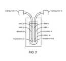
- FIG. 2illustrates a temperature sensor with redundant thermistors.
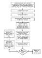
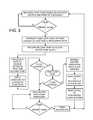
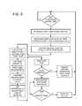
- FIGS. 3-7are flow diagrams illustrating features of operation of the spa control system.
- Sensor 2is made up of dual, solid state temperature sensing elements Thermistor 3 and Thermistor 4 connected to separate input ports of Microprocessor 1 with wires 5 , 6 , 7 , and 8 .
- Thermistors 3 and 4may share a common housing means, which is placed near the heating element of a spa heater. Both thermistors are not required for the invention but are included to meet the redundancy requirements of UL 1563 concerning independent circuits to control the heater.
- the measurements of the two thermistorsmay be averaged together for the purpose of controlling the water temperature. Since the thermistors are in exactly the same location, their temperature measurements should be nearly the same. If the two thermistors report measurements that are different by a prescribed amount, the microprocessor will de-energize the heater and indicate to the user that the sensor is defective. ( FIG. 7 )
- both measurementsare constantly shown so that the user can see the nature of the problem, if any. This data is presented in lieu of error messages that contain no real information.
- Heater 10is coupled to microprocessor 1 through redundant circuit means 12 and 13 .
- sensor 2measures temperatures inside heater 10 , which may, or may not, contain water.
- FIG. 1AThe invention can be accomplished with sensor 2 mounted external to the heater housing, or mounted in a dry well arrangement; however, reaction times for problems are shorter if sensor 2 is in close proximity to the heating element of heater 10 . This can be accomplished by providing a threaded hole in the heater housing and securing sensor 2 in the hole with a standard compression fitting.
- microprocessor 1When the temperature measurement of sensor 2 is less, by a prescribed amount, than the set temperature, maintained by microprocessor 1 , microprocessor 1 will cause pump 9 to be energized in preparation for energizing heater 10 , as soon as water flow is found to be adequate. Pump 9 will circulate water from the vessel containing water for one or two minutes, or until the rate of temperature change, as seen by sensor 2 , is less than a prescribed rate of change. This stabilized temperature measurement will be recorded by microprocessor 1 as the actual water temperature in the spa prior to the flow test. ( FIG. 3 )
- the first step in the flow testis to turn off, or de-energize, circulation pump 9 .
- the next stepis to turn on heater 10 , but only for a few seconds.
- sensor 2is monitored for a rise in temperature. With no circulation in heater 10 , a rise of several degrees is expected within, say, 30 seconds.
- pump 9is turned back on so that the cooling water can dissipate the recent heat rise within a few seconds. If the flow is good, the temperature at sensor 2 will return to near the water temperature recorded prior to the brief heater activation.
- heater 10can be turned or a longer period to heat the water to, or beyond, the set temperature. ( FIG. 4 )
- a signalsuch as a flashing LED, or a change of color somewhere on a user interface, can be provided to the user to explain why heating is not taking place. ( FIG. 3 )
- Use of the present inventionis not restricted to spas with a high rate of water flow through the heater.
- a temperature difference between two reference points at the heateris not used, but rather a cooling rate of change. Because only a small amount of flow is required to make an accurate measurement, the invention can be used on spas with low water flow, or vertical, heaters.
- Sensor 2must be carefully monitored for a rapid increase in temperature inside the heater, or for an increase in temperature over a longer period of time that is unreasonable and indicative of a dirty filter, for example. Comparing the rise in temperature with the time required to reach that temperature does this. If the rate of change is greater than a prescribed rate, poor flow may be causing the heater to become hotter than the water in the vessel. Heater 10 will be de-energized immediately and another flow test attempted.
- the water temperature in the vesselmay be different than the water temperature in heater 10 , due to the differences in volume and location. If sensor 2 measures a temperature lower than the set temperature, microprocessor 1 will normally turn on pump 9 and heater 10 to reach, at least, the set temperature. If the spa water was not as cold as the heater 10 temperature, which caused pump 9 to be turned on, pump 9 will quickly turn back off as soon as the real water temperature is seen by sensor 2 .
- Microprocessor 1can keep a record of the differences between the apparent water temperature in heater 10 and the real water temperature as will be discovered when pump 9 is turned on and run for a minute or two. This difference can now be applied as a calculated temperature offset to the next heater 10 temperature measurement. For example, if the set temperature is 100 degrees, pump 9 will be turned on at perhaps, 99 degrees. Once pump 9 has circulated the spa water through heater 10 it may be seen that it was unnecessary to turn on pump 9 with only one degree of difference, so one degree of offset will be added to the heater temperature before pump 9 is turned on again at 98 degrees. This process will continue until the heater temperature with the offset added closely matches the actual spa water temperature when the pump is first activated in preparation of a heating cycle.
- FIG. 5An additional improvement may be made after observing the rate of change in the heater temperature while the pump is off. In the previous example, the offset may be adjusted to a larger number, perhaps five degrees, if the heater is found to be cooling very quickly. ( FIG. 5A ) This would provide a closer match between the water in the vessel and the user preferred temperature at the time the pump and heater are turned on.
- the pumpis turned on to check for water temperature after a certain period of time has passed.
- This period of timeis constantly adjusted by adding or subtracting time, based on the accuracy of the most recent period of time in determining the true need for heating. For example, if the requirement is to activate the heater only after the spa water has dropped 1 degree lower than the set temperature, then the comparison of real water temperature to set temperature minus 1 degree will yield a difference of some number of degrees. The number of degrees thus found as a difference will be the basis for adding or subtracting time for the next period for the pump to be off. ( FIG. 5 )
- the set temperatureis 100 F.
- the pumphas been off for 120 minutes.
- the prescribed water temperature to turn the heater onmay be 99 F.
- the pumpis turned on after 120 minutes and the temperature at the heater sensor stabilizes at, say, 98 F., it will be known that the pump has been off too long.
- the previous 120 minute periodmay now be reduced by 30 minutes, to a new value of 90 minutes. If, however, the stabilized water temperature was only 97 F., a bigger adjustment may be in order.
- the new periodmay be adjusted to 60 minutes. Obviously, a certain amount of time can be added to the next period if the actual water temperature is higher than the target temperature. ( FIG. 5 )
- FIG. 2illustrates a possible construction of sensor 2 .
- Two solid-state sensor elementsare represented by thermistor 3 and thermistor 4 .
- Devices other than thermistors, such as PN junctions,are also well known for this type of application. Only thermistor 3 or thermistor 4 is required for the invention to operate as described.
- UL standard 1563 for electric spasrequires totally redundant circuitry to control each power line of a spa heater, so it is convenient to place two thermistors at the same location in the heater.
- Housing 16 of sensor 2may be a closed end stainless steel tube of a size that fits into the heater using a standard compression fitting.
- Thermistor 3is attached to connector 17 with wires 5 and 6 suitable for the purpose.
- Thermistor 4is attached to connector 18 with wires 7 and 8 .
- housing 16may be filled with a heat conductive epoxy or similar material, as long as the material is not electrically conductive.
- Connectors 17 and 18provide electrical coupling to a microprocessor through circuitry means.
- microprocessor 1is connected to colored LEDs 26 by way of LED circuitry 25 , and to speaker 15 by way of audio circuitry 14 .
- decorative LEDs 26are used to flash red LEDs if the water is hotter than the set temperature and to flash blue LEDs if the water is colder than the set temperature.
- the flash ratemay be related to the differences, so that a very fast flash of the red LEDs within LEDs 26 may indicate that the water is so hot that a high limit condition has been reached.
- a very fast flash rate of the blue LEDs within LEDs 26may indicate that the spa's plumbing is in danger of freezing.
- Another LED color, such as yellow,may be used to show that the water flow is inadequate and caution must be used, because the spa is unable to heat the water.
- the integrated audio system shown in FIG. 1is used to speak to the user.
- An error conditionsuch as water that is too hot, too cold, or not flowing, is communicated from microprocessor 1 to the user by speaker 15 , coupled through audio circuitry 14 , which includes a voice synthesizer.
Landscapes
- Engineering & Computer Science (AREA)
- Physics & Mathematics (AREA)
- General Engineering & Computer Science (AREA)
- Mechanical Engineering (AREA)
- Combustion & Propulsion (AREA)
- Chemical & Material Sciences (AREA)
- Thermal Sciences (AREA)
- Health & Medical Sciences (AREA)
- Public Health (AREA)
- Physical Education & Sports Medicine (AREA)
- Veterinary Medicine (AREA)
- General Health & Medical Sciences (AREA)
- Animal Behavior & Ethology (AREA)
- Life Sciences & Earth Sciences (AREA)
- Rehabilitation Therapy (AREA)
- Pain & Pain Management (AREA)
- Epidemiology (AREA)
- Computer Hardware Design (AREA)
- Instantaneous Water Boilers, Portable Hot-Water Supply Apparatuses, And Control Of Portable Hot-Water Supply Apparatuses (AREA)
Abstract
Description
Claims (25)
Priority Applications (1)
| Application Number | Priority Date | Filing Date | Title |
|---|---|---|---|
| US12/661,185US8406932B2 (en) | 2009-09-28 | 2010-03-12 | Spa control with improved heater management system |
Applications Claiming Priority (2)
| Application Number | Priority Date | Filing Date | Title |
|---|---|---|---|
| US12/586,712US8392027B2 (en) | 2009-09-28 | 2009-09-28 | Spa control system with improved flow monitoring |
| US12/661,185US8406932B2 (en) | 2009-09-28 | 2010-03-12 | Spa control with improved heater management system |
Related Parent Applications (1)
| Application Number | Title | Priority Date | Filing Date |
|---|---|---|---|
| US12/586,712Continuation-In-PartUS8392027B2 (en) | 2009-09-28 | 2009-09-28 | Spa control system with improved flow monitoring |
Publications (2)
| Publication Number | Publication Date |
|---|---|
| US20110219530A1 US20110219530A1 (en) | 2011-09-15 |
| US8406932B2true US8406932B2 (en) | 2013-03-26 |
Family
ID=44558498
Family Applications (1)
| Application Number | Title | Priority Date | Filing Date |
|---|---|---|---|
| US12/661,185Active2030-12-26US8406932B2 (en) | 2009-09-28 | 2010-03-12 | Spa control with improved heater management system |
Country Status (1)
| Country | Link |
|---|---|
| US (1) | US8406932B2 (en) |
Cited By (6)
| Publication number | Priority date | Publication date | Assignee | Title |
|---|---|---|---|---|
| US9362740B1 (en) | 2014-02-06 | 2016-06-07 | Joseph G. Elnar | Electrical water heater air entrapment detection |
| US20160161347A1 (en)* | 2013-08-28 | 2016-06-09 | Nissan Motor Co., Ltd. | Sensor abnormality determining apparatus |
| US20160187027A1 (en)* | 2013-08-09 | 2016-06-30 | Winslim | Method for Managing the Heating of Water in a Tank of a Water Heater |
| US9897084B2 (en) | 2013-07-25 | 2018-02-20 | Fluid Handling Llc | Sensorless adaptive pump control with self-calibration apparatus for hydronic pumping system |
| US10441503B2 (en) | 2016-12-27 | 2019-10-15 | Richard T. FRENCH | SPA with temperature responsive pump activation and deactivation independent of heater activation |
| US10876742B2 (en)* | 2017-02-24 | 2020-12-29 | Ronen TADMOR | Sabbath controller for a hot water tank |
Families Citing this family (5)
| Publication number | Priority date | Publication date | Assignee | Title |
|---|---|---|---|---|
| US8392027B2 (en)* | 2009-09-28 | 2013-03-05 | Balboa Instruments, Inc. | Spa control system with improved flow monitoring |
| US20130178989A1 (en)* | 2012-01-11 | 2013-07-11 | Hamilton Sundstrand Corporation | Air temperature controller |
| ES2820198T3 (en) | 2013-07-18 | 2021-04-19 | Intex Marketing Ltd | Inflatable hydrotherapy bath |
| CN103600502A (en) | 2013-11-25 | 2014-02-26 | 明达实业(厦门)有限公司 | Melting technology of inflatable products |
| JP6223279B2 (en)* | 2014-05-26 | 2017-11-01 | 三菱電機株式会社 | Water heater |
Citations (16)
| Publication number | Priority date | Publication date | Assignee | Title |
|---|---|---|---|---|
| US5056712A (en)* | 1989-12-06 | 1991-10-15 | Enck Harry J | Water heater controller |
| US5361215A (en) | 1987-05-27 | 1994-11-01 | Siege Industries, Inc. | Spa control system |
| US5550753A (en) | 1987-05-27 | 1996-08-27 | Irving C. Siegel | Microcomputer SPA control system |
| US6282370B1 (en) | 1998-09-03 | 2001-08-28 | Balboa Instruments, Inc. | Control system for bathers |
| US6756907B2 (en)* | 2002-06-11 | 2004-06-29 | Jerrell Penn Hollaway | Maintainance support system for an electrical apparatus |
| US20050167419A1 (en)* | 2004-02-02 | 2005-08-04 | Christian Brochu | Temperature control system for a bathing unit |
| US20050177281A1 (en)* | 2004-01-23 | 2005-08-11 | Aos Holding Company | Apparatus and method of controlling the apparatus |
| US6965815B1 (en) | 1987-05-27 | 2005-11-15 | Bilboa Instruments, Inc. | Spa control system |
| US6976636B2 (en)* | 2004-01-12 | 2005-12-20 | Truheat, Inc. | Heater having over temperature shut off control |
| US20060162719A1 (en)* | 2004-11-30 | 2006-07-27 | 9090-3493 Quebec Inc. | Water flow detection system for a bathing unit |
| US20060238931A1 (en)* | 2005-04-22 | 2006-10-26 | Cline David J | Shutoff system for pool or spa |
| US20070058315A1 (en)* | 2005-09-09 | 2007-03-15 | Maddox Harold D | Controlling spas |
| US20070210068A1 (en)* | 2006-03-03 | 2007-09-13 | Allied Precision Industries, Inc. | Fluid heating system and method |
| US20080168599A1 (en)* | 2007-01-12 | 2008-07-17 | Caudill Dirk A | Spa system with flow control feature |
| US7440864B2 (en)* | 1999-11-30 | 2008-10-21 | Balboa Instruments, Inc. | Controller system for pool and/or spa |
| US20090126100A1 (en)* | 2007-11-19 | 2009-05-21 | Michael Lee Kenoyer | Systems and Methods for Bathtub Heating |
- 2010
- 2010-03-12USUS12/661,185patent/US8406932B2/enactiveActive
Patent Citations (20)
| Publication number | Priority date | Publication date | Assignee | Title |
|---|---|---|---|---|
| US6965815B1 (en) | 1987-05-27 | 2005-11-15 | Bilboa Instruments, Inc. | Spa control system |
| US5361215A (en) | 1987-05-27 | 1994-11-01 | Siege Industries, Inc. | Spa control system |
| US5550753A (en) | 1987-05-27 | 1996-08-27 | Irving C. Siegel | Microcomputer SPA control system |
| US5559720A (en) | 1987-05-27 | 1996-09-24 | Irving C. Siegel | Spa control system |
| US6253227B1 (en) | 1987-05-27 | 2001-06-26 | Balboa Instruments, Inc. | Spa control system |
| US6976052B2 (en) | 1987-05-27 | 2005-12-13 | Balboa Instruments, Inc. | Spa control system |
| US5056712A (en)* | 1989-12-06 | 1991-10-15 | Enck Harry J | Water heater controller |
| US6282370B1 (en) | 1998-09-03 | 2001-08-28 | Balboa Instruments, Inc. | Control system for bathers |
| US6590188B2 (en) | 1998-09-03 | 2003-07-08 | Balboa Instruments, Inc. | Control system for bathers |
| US7440864B2 (en)* | 1999-11-30 | 2008-10-21 | Balboa Instruments, Inc. | Controller system for pool and/or spa |
| US6756907B2 (en)* | 2002-06-11 | 2004-06-29 | Jerrell Penn Hollaway | Maintainance support system for an electrical apparatus |
| US6976636B2 (en)* | 2004-01-12 | 2005-12-20 | Truheat, Inc. | Heater having over temperature shut off control |
| US20050177281A1 (en)* | 2004-01-23 | 2005-08-11 | Aos Holding Company | Apparatus and method of controlling the apparatus |
| US20050167419A1 (en)* | 2004-02-02 | 2005-08-04 | Christian Brochu | Temperature control system for a bathing unit |
| US20060162719A1 (en)* | 2004-11-30 | 2006-07-27 | 9090-3493 Quebec Inc. | Water flow detection system for a bathing unit |
| US20060238931A1 (en)* | 2005-04-22 | 2006-10-26 | Cline David J | Shutoff system for pool or spa |
| US20070058315A1 (en)* | 2005-09-09 | 2007-03-15 | Maddox Harold D | Controlling spas |
| US20070210068A1 (en)* | 2006-03-03 | 2007-09-13 | Allied Precision Industries, Inc. | Fluid heating system and method |
| US20080168599A1 (en)* | 2007-01-12 | 2008-07-17 | Caudill Dirk A | Spa system with flow control feature |
| US20090126100A1 (en)* | 2007-11-19 | 2009-05-21 | Michael Lee Kenoyer | Systems and Methods for Bathtub Heating |
Cited By (10)
| Publication number | Priority date | Publication date | Assignee | Title |
|---|---|---|---|---|
| US9897084B2 (en) | 2013-07-25 | 2018-02-20 | Fluid Handling Llc | Sensorless adaptive pump control with self-calibration apparatus for hydronic pumping system |
| US20160187027A1 (en)* | 2013-08-09 | 2016-06-30 | Winslim | Method for Managing the Heating of Water in a Tank of a Water Heater |
| US10060650B2 (en)* | 2013-08-09 | 2018-08-28 | Winslim | Method for managing the heating of water in a tank of a water heater |
| US20160161347A1 (en)* | 2013-08-28 | 2016-06-09 | Nissan Motor Co., Ltd. | Sensor abnormality determining apparatus |
| US9823140B2 (en)* | 2013-08-28 | 2017-11-21 | Nissan Motor Co., Ltd. | Sensor abnormality determining apparatus |
| US9362740B1 (en) | 2014-02-06 | 2016-06-07 | Joseph G. Elnar | Electrical water heater air entrapment detection |
| US10441503B2 (en) | 2016-12-27 | 2019-10-15 | Richard T. FRENCH | SPA with temperature responsive pump activation and deactivation independent of heater activation |
| US11123262B2 (en) | 2016-12-27 | 2021-09-21 | Barefoot Spas Llc | Spa with water purification system |
| US11253427B2 (en) | 2016-12-27 | 2022-02-22 | Barefoot Spas Llc | Spa with air intake system |
| US10876742B2 (en)* | 2017-02-24 | 2020-12-29 | Ronen TADMOR | Sabbath controller for a hot water tank |
Also Published As
| Publication number | Publication date |
|---|---|
| US20110219530A1 (en) | 2011-09-15 |
Similar Documents
| Publication | Publication Date | Title |
|---|---|---|
| US8406932B2 (en) | Spa control with improved heater management system | |
| US10119537B2 (en) | Pump monitoring device | |
| CN1991273B (en) | Fluid-heating apparatus, circuit for heating a fluid, and method of operating the same | |
| CN100412460C (en) | Fluid heating and control system | |
| US20100086289A1 (en) | Modular tankless water heater with precise power control circuitry and structure | |
| JPS5916673B2 (en) | Road ice information device | |
| US7834772B2 (en) | Copper-watcher | |
| KR102363702B1 (en) | Single Lever Smart Cartridge for Tap Fittings, Single Lever Smart Tap Fittings, and Smart Care Methods for Single Lever Tap Fittings | |
| US7473868B2 (en) | Fail safe HVAC temperature and medium presence sensor | |
| US20120047927A1 (en) | Solid state control system | |
| WO2012007753A1 (en) | Sensing and monitoring apparatus | |
| JP5705332B2 (en) | Instant water heater | |
| US8392027B2 (en) | Spa control system with improved flow monitoring | |
| US9188283B2 (en) | Temperature monitoring apparatus for a steam trap | |
| CN107143904B (en) | Continuous water supply type room heating temperature control and heat metering device and method | |
| US20190021944A1 (en) | Spa control wtih novel heater management system | |
| GB2569471B (en) | Flow detection device | |
| EP3195693B1 (en) | Systems and methods to detect heater malfunction and prevent dry burning | |
| JP4442759B2 (en) | Piping freezing prevention device | |
| EP3282337B2 (en) | Heat exchanger system and method for detecting a relocation of a temperature sensor in a heat exchanger system | |
| CN103615567B (en) | Constant-temperature water valve | |
| GB2368896A (en) | Heat exchange system, temperature sensor arrangement and operation | |
| CN104713666A (en) | Leak-proof control meter for ultrasonic hot water zone | |
| JPH11270900A (en) | Forced circulation bath kettle with hot water filling function | |
| CN216667997U (en) | Hot water electric control circulating device applied to water heater |
Legal Events
| Date | Code | Title | Description |
|---|---|---|---|
| AS | Assignment | Owner name:BALBOA INSTRUMENTS, INC., CALIFORNIA Free format text:ASSIGNMENT OF ASSIGNORS INTEREST;ASSIGNOR:HOLLAWAY, JERRELL P., MR.;REEL/FRAME:025369/0374 Effective date:20101110 | |
| STCF | Information on status: patent grant | Free format text:PATENTED CASE | |
| AS | Assignment | Owner name:PNC BANK, NATIONAL ASSOCIATION, PENNSYLVANIA Free format text:SECURITY AGREEMENT;ASSIGNORS:BALBOA WATER GROUP, LLC;BALBOA INSTRUMENTS, INC.;G-G DISTRIBUTION AND DEVELOPMENT CO., INC.;REEL/FRAME:030955/0130 Effective date:20130731 | |
| AS | Assignment | Owner name:BALBOA WATER GROUP, INC., CALIFORNIA Free format text:ASSIGNMENT OF ASSIGNORS INTEREST;ASSIGNOR:BALBOA INSTRUMENTS, INC.;REEL/FRAME:030965/0092 Effective date:20130731 | |
| AS | Assignment | Owner name:BALBOA INSTRUMENTS, INC., CALIFORNIA Free format text:CORRECTIVE ASSIGNMENT TO CORRECT THE TO REMOVE INCORRECT SERIAL NUMBER 12/536,712 PREVIOUSLY RECORDED ON REEL 025369 FRAME 0374. ASSIGNOR(S) HEREBY CONFIRMS THE ASSIGNMENT;ASSIGNOR:HOLLAWAY, JERRELL P.;REEL/FRAME:031912/0812 Effective date:20101110 | |
| FPAY | Fee payment | Year of fee payment:4 | |
| AS | Assignment | Owner name:BMO HARRIS BANK N.A., AS ADMINISTRATIVE AGENT, ILLINOIS Free format text:PATENT SECURITY AGREEMENT;ASSIGNOR:BALBOA WATER GROUP, LLC;REEL/FRAME:051906/0375 Effective date:20151117 | |
| AS | Assignment | Owner name:BALBOA WATER GROUP, LLC, CALIFORNIA Free format text:ENTITY CONVERSION;ASSIGNOR:BALBOA WATER GROUP, INC.;REEL/FRAME:052150/0661 Effective date:20130731 | |
| AS | Assignment | Owner name:SPA & BATH HOLDINGS, INC., CALIFORNIA Free format text:RELEASE BY SECURED PARTY;ASSIGNOR:PNC BANK, NATIONAL ASSOCIATION;REEL/FRAME:052918/0717 Effective date:20151117 Owner name:BALBOA WATER GROUP, LLC, CALIFORNIA Free format text:RELEASE BY SECURED PARTY;ASSIGNOR:PNC BANK, NATIONAL ASSOCIATION;REEL/FRAME:052918/0717 Effective date:20151117 Owner name:G-G DISTRIBUTION AND DEVELOPMENT CO., INC., CALIFORNIA Free format text:RELEASE BY SECURED PARTY;ASSIGNOR:PNC BANK, NATIONAL ASSOCIATION;REEL/FRAME:052918/0717 Effective date:20151117 Owner name:BALBOA INSTRUMENTS, INC., CALIFORNIA Free format text:RELEASE BY SECURED PARTY;ASSIGNOR:PNC BANK, NATIONAL ASSOCIATION;REEL/FRAME:052918/0717 Effective date:20151117 Owner name:BALBOA WATER GROUP, INC., CALIFORNIA Free format text:RELEASE BY SECURED PARTY;ASSIGNOR:PNC BANK, NATIONAL ASSOCIATION;REEL/FRAME:052918/0717 Effective date:20151117 | |
| MAFP | Maintenance fee payment | Free format text:PAYMENT OF MAINTENANCE FEE, 8TH YEAR, LARGE ENTITY (ORIGINAL EVENT CODE: M1552); ENTITY STATUS OF PATENT OWNER: LARGE ENTITY Year of fee payment:8 | |
| AS | Assignment | Owner name:PNC BANK, NATIONAL ASSOCIATION, AS ADMINISTRATIVE AGENT, PENNSYLVANIA Free format text:NOTICE OF GRANT OF SECURITY INTEREST IN PATENTS;ASSIGNOR:BALBOA WATER GROUP, LLC;REEL/FRAME:054341/0169 Effective date:20201028 Owner name:BALBOA WATER GROUP, LLC, CALIFORNIA Free format text:RELEASE BY SECURED PARTY;ASSIGNOR:BMO HARRIS BANK, N.A.;REEL/FRAME:054344/0627 Effective date:20201106 | |
| AS | Assignment | Owner name:BALBOA WATER GROUP, LLC, CALIFORNIA Free format text:CORRECTIVE ASSIGNMENT TO CORRECT THE PROPERTY NUMBER 8191183 PREVIOUSLY RECORDED AT REEL: 054344 FRAME: 0637. ASSIGNOR(S) HEREBY CONFIRMS THE RELEASE OF SECURITY INTEREST;ASSIGNOR:BMO HARRIS BANK, N.A.;REEL/FRAME:057144/0919 Effective date:20201106 | |
| MAFP | Maintenance fee payment | Free format text:PAYMENT OF MAINTENANCE FEE, 12TH YEAR, LARGE ENTITY (ORIGINAL EVENT CODE: M1553); ENTITY STATUS OF PATENT OWNER: LARGE ENTITY Year of fee payment:12 |