US8406450B2 - Thermoacoustic device with heat dissipating structure - Google Patents
Thermoacoustic device with heat dissipating structureDownload PDFInfo
- Publication number
- US8406450B2 US8406450B2US12/768,059US76805910AUS8406450B2US 8406450 B2US8406450 B2US 8406450B2US 76805910 AUS76805910 AUS 76805910AUS 8406450 B2US8406450 B2US 8406450B2
- Authority
- US
- United States
- Prior art keywords
- electrode
- thermoacoustic
- carbon nanotube
- thermoacoustic device
- electrodes
- Prior art date
- Legal status (The legal status is an assumption and is not a legal conclusion. Google has not performed a legal analysis and makes no representation as to the accuracy of the status listed.)
- Expired - Fee Related, expires
Links
Images


Classifications
- F—MECHANICAL ENGINEERING; LIGHTING; HEATING; WEAPONS; BLASTING
- F28—HEAT EXCHANGE IN GENERAL
- F28D—HEAT-EXCHANGE APPARATUS, NOT PROVIDED FOR IN ANOTHER SUBCLASS, IN WHICH THE HEAT-EXCHANGE MEDIA DO NOT COME INTO DIRECT CONTACT
- F28D15/00—Heat-exchange apparatus with the intermediate heat-transfer medium in closed tubes passing into or through the conduit walls ; Heat-exchange apparatus employing intermediate heat-transfer medium or bodies
- F28D15/02—Heat-exchange apparatus with the intermediate heat-transfer medium in closed tubes passing into or through the conduit walls ; Heat-exchange apparatus employing intermediate heat-transfer medium or bodies in which the medium condenses and evaporates, e.g. heat pipes
- F28D15/0275—Arrangements for coupling heat-pipes together or with other structures, e.g. with base blocks; Heat pipe cores
- F—MECHANICAL ENGINEERING; LIGHTING; HEATING; WEAPONS; BLASTING
- F28—HEAT EXCHANGE IN GENERAL
- F28F—DETAILS OF HEAT-EXCHANGE AND HEAT-TRANSFER APPARATUS, OF GENERAL APPLICATION
- F28F1/00—Tubular elements; Assemblies of tubular elements
- F28F1/10—Tubular elements and assemblies thereof with means for increasing heat-transfer area, e.g. with fins, with projections, with recesses
- F28F1/12—Tubular elements and assemblies thereof with means for increasing heat-transfer area, e.g. with fins, with projections, with recesses the means being only outside the tubular element
- F28F1/24—Tubular elements and assemblies thereof with means for increasing heat-transfer area, e.g. with fins, with projections, with recesses the means being only outside the tubular element and extending transversely
- F28F1/32—Tubular elements and assemblies thereof with means for increasing heat-transfer area, e.g. with fins, with projections, with recesses the means being only outside the tubular element and extending transversely the means having portions engaging further tubular elements
- H—ELECTRICITY
- H04—ELECTRIC COMMUNICATION TECHNIQUE
- H04R—LOUDSPEAKERS, MICROPHONES, GRAMOPHONE PICK-UPS OR LIKE ACOUSTIC ELECTROMECHANICAL TRANSDUCERS; DEAF-AID SETS; PUBLIC ADDRESS SYSTEMS
- H04R23/00—Transducers other than those covered by groups H04R9/00 - H04R21/00
- H04R23/002—Transducers other than those covered by groups H04R9/00 - H04R21/00 using electrothermic-effect transducer
Definitions
- thermoacoustic devicesparticularly, to a carbon nanotube based thermoacoustic device with a heating dissipating structure.
- a typical speakeris an electro-acoustic transducer that converts electrical signals into sound.
- Different types of speakerscan be categorized according to their working principles, such as electro-dynamic speakers, electromagnetic speakers, electrostatic speakers and piezoelectric speakers. However, these types use mechanical vibration to produce sound waves by “electro-mechanical-acoustic” conversion. Among the various types, the electro-dynamic speakers are most widely used.
- the electro-dynamic speaker 500typically includes a voice coil 502 , a magnet 504 and a cone 506 .
- the voice coil 502is an electrical conductor, and is placed in the magnetic field of the magnet 504 .
- an electrical currentto the voice coil 502 , a mechanical vibration of the cone 506 is produced due to the interaction between the electromagnetic field produced by the voice coil 502 and the magnetic field of the magnets 504 , thus producing sound waves by kinetically pushing the air.
- the structure of the electric-powered loudspeaker 500is dependent on magnetic fields and often weighty magnets.
- Thermoacoustic effectis the conversion of heat to acoustic signals.
- signalsare inputted into a thermoacoustic element, heating is produced in the thermoacoustic element according to the variations of the signal and/or signal strength. Heat is propagated into the surrounding medium. The heating of the medium causes thermal expansion and produces pressure waves in the surrounding medium, resulting in sound wave generation.
- Such an acoustic effect induced by temperature wavesis commonly called “the thermoacoustic effect”.
- thermophone based on the thermoacoustic effectwas created by H. D. Arnold and I. B. Crandall (H. D. Arnold and I. B. Crandall, “The thermophone as a precision source of sound”, Phys. Rev. 10, pp 22-38 (1917)).
- a platinum strip with a thickness of 7 ⁇ 10 ⁇ 5 cmwas used as a thermoacoustic element.
- the heat capacity per unit area of the platinum strip with the thickness of 7 ⁇ 10 ⁇ 5 cmis 2 ⁇ 10 ⁇ 4 J/cm 2 *K.
- the thermophone adopting the platinum stripproduces extremely weak sound.
- Carbon nanotubesare a novel carbonaceous material having extremely small size and extremely large specific surface area. Carbon nanotubes have received a great deal of interest since the early 1990s, and have interesting and potentially useful electrical and mechanical properties, and have been widely used in a plurality of fields. Fan et al. discloses a thermoacoustic device with simpler structure and smaller size, working without the magnet in an article of “Flexible, Stretchable, Transparent Carbon Nanotube Thin Film Loudspeakers”, Fan et al., Nano Letters, Vol. 8 (12), 4539-4545 (2008). The thermoacoustic device includes a sound wave generator which is a carbon nanotube film.
- thermoacoustic devicehas a large specific surface area, and extremely small heat capacity per unit area.
- the sound wave generatoremits sound with a wide frequency response range. Accordingly, the thermoacoustic device adopting the carbon nanotube film has a potential to be used in places of the loudspeakers of the prior art.
- the carbon nanotube filmis soft and can be easily damaged, thus, a base or support is usually adopted to support and protect the carbon nanotube film.
- a base or supportis usually adopted to support and protect the carbon nanotube film.
- the carbon nanotube filmwill eventually generate heat stored in the base, which may scald a user's hand or may burn anything near the base. The performance of the thermoacoustic device will be adversely affected.
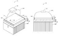
- FIG. 1is a schematic structural view of one embodiment of a thermoacoustic device.
- FIG. 2illustrates a view taken on line II-II of FIG. 1 .
- FIG. 3shows a Scanning Electron Microscope (SEM) image of one embodiment of a drawn carbon nanotube film.
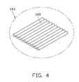
- FIG. 4is a schematic, enlarged view of a carbon nanotube segment in the drawn carbon nanotube film of FIG. 3 .
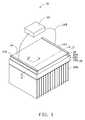
- FIG. 5is similar to FIG. 1 , with the addition of a fan.
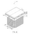
- FIG. 6is a schematic structural view of another embodiment of a thermoacoustic device.
- FIG. 7illustrates a view taken on line VII-VII of FIG. 6 .
- FIG. 8is a schematic structural view of yet another embodiment of a thermoacoustic device.
- FIG. 9illustrates a view taken on line IX-IX of FIG. 8 .
- FIG. 10is an enlarged view of a heat pipe of FIG. 9 .
- FIG. 11is similar to FIG. 8 , but viewed from another aspect.
- FIG. 12is a schematic structural view of a conventional loudspeaker according to the prior art.
- thermoacoustic device 10comprises a heat dissipating structure 18 , two supporting elements 16 , a thermoacoustic element 14 , a first electrode 142 , a second electrode 144 and a signal input device 12 .
- the thermoacoustic element 14is disposed on and spaced from the heat dissipating structure 18 through the supporting elements 16 .
- the signal input device 12is connected with the thermoacoustic element 14 via the first electrode 142 and the second electrode 144 .
- the heat dissipating structure 18comprises a base 185 and a plurality of fins 188 .
- the base 185can be a flat board, and has a first surface 184 and a second surface 186 opposite to the first surface 184 .
- the base 185can be made of materials which have good thermal conductivity and have low far-infrared absorption, such as metals including copper and aluminum.
- the area of the base 185can be designed according to the actual need so long as the area of the base 185 is not smaller than that of the thermoacoustic element 14 .
- the base 185is a copper piece, and has a thickness ranging from about 1 mm to about 5 mm. Both the total cost and thickness of the thermoacoustic device 10 can be lowered due to the relative small thickness of the base 185 .
- the fins 188are arranged on the second surface 186 , which is the bottom surface of the base 185 when the thermoacoustic device 10 is positioned in the position shown in FIG. 1 .
- the fins 188are made of thermal conductive materials, such as metals including gold, silver, copper, iron, aluminum and so on. In this embodiment, the fins 188 are copper pieces having a thickness ranging from about 0.5 mm to about 1 mm.
- the fins 188can be fixed on the second surface 186 via welding or screws, or other methods.
- the fins 188 and the base 185can also be made from one piece of material.
- the fins 188can transfer the heat absorbed by the base 185 away and dissipate the absorbed heat to the ambient environment, thereby lowering the temperature of the base 185 .
- the heat dissipating structure 18can further comprise a fan 19 mounted on the fins 188 .
- the fan 19can be secured on the fins 188 via a clip (not shown) or an engagement between the fan 19 and the fins 188 .
- the fan 19blows air generating airflow towards the fins 188 to take heat therefrom, thus, the heat-dissipation efficiency of the fins 188 can be improved.
- the supporting elements 16are disposed on the first surface 184 and used to support the thermoacoustic element 14 thereon.
- the supporting elements 16can be attached to opposite end portions of the first surface 184 via insulating adhesive or screws.
- the shape of the supporting elements 16is not limited so long as the supporting elements 16 can support the thermoacoustic element 14 thereon.
- the supporting elements 16can be made of materials which are insulative and adiabatic. In one embodiment, the supporting elements 16 are rigid and are made of diamond, glass or quartz. In another embodiment, the supporting elements 16 are flexible and are made of plastic or resin. If the thermoacoustic element 14 has a large area, there can be three or more supporting elements 16 which are disposed on the first surface 184 with a uniform interval formed between adjacent supporting elements 16 .
- the supporting elements 16are strip shaped and made of quartz.
- a direction from one of the supporting elements 16 to the other one of the supporting elements 16is defined as a length direction L (shown in FIG. 1 ) of the thermoacoustic element 14 .
- a direction perpendicular to the length direction Lis defined as a width direction W (shown in FIG. 1 ) of the thermoacoustic element 14 and the supporting elements 16 .
- the width of the supporting elements 16are designed to be no smaller than the width of the thermoacoustic element 14 so that the thermoacoustic element 14 can be firmly secured on the supporting elements 16 .
- thermoacoustic element 14is disposed on the first surface 184 via the supporting elements 16 .
- the thermoacoustic element 14is substantially parallel to and spaced from the first surface 184 .
- the thermoacoustic element 14can be secured on the supporting elements 16 via adhesive.
- the thermoacoustic element 14has a low heat capacity per unit area that can realize “electrical-thermal-sound” conversion.
- the thermoacoustic element 14can have a large specific surface area to cause pressure oscillations in the surrounding medium by the temperature waves generated by the thermoacoustic element 14 .
- the heat capacity per unit area of the thermoacoustic element 14can be less than 2 ⁇ 10-4 J/cm 2 *K.
- the thermoacoustic element 14includes or can be a carbon nanotube structure.
- the carbon nanotube structurecan have a large specific surface area (e.g., above 30 m 2 /g).
- the heat capacity per unit area of the carbon nanotube structureis less than 2 ⁇ 10-4 J/cm 2 *K. In one embodiment, the heat capacity per unit area of the carbon nanotube structure is less than or equal to 1.7 ⁇ 10-6 J/cm 2 *K.
- the carbon nanotube structurecan include a plurality of carbon nanotubes uniformly distributed therein, and the carbon nanotubes therein can be joined by van der Waals attractive force therebetween. It is understood that the carbon nanotube structure must include metallic carbon nanotubes.
- the carbon nanotubes in the carbon nanotube structurecan be orderly or disorderly arranged.
- disordered carbon nanotube structureincludes, but is not limited to, a structure where the carbon nanotubes are arranged along many different directions, arranged such that the number of carbon nanotubes arranged along each different direction can be almost the same (e.g. uniformly disordered); and/or entangled with each other.
- Organic carbon nanotube structureincludes, but is not limited to, a structure where the carbon nanotubes are arranged in a systematic manner, e.g., the carbon nanotubes are arranged approximately along a same direction and or have two or more sections within each of which the carbon nanotubes are arranged approximately along a same direction (different sections can have different directions).
- the carbon nanotubes in the carbon nanotube structurecan be selected from single-walled, double-walled, and/or multi-walled carbon nanotubes. Diameters of the single-walled carbon nanotubes range from about 0.5 nanometers to about 50 nanometers. Diameters of the double-walled carbon nanotubes range from about 1 nanometer to about 50 nanometers. Diameters of the multi-walled carbon nanotubes range from about 1.5 nanometers to about 50 nanometers. It is also understood that there may be many layers of ordered and/or disordered carbon nanotube films in the carbon nanotube structure.
- the carbon nanotube structuremay have a substantially planar structure.
- the thickness of the carbon nanotube structuremay range from about 0.5 nanometers to about 1 millimeter. The smaller the specific surface area of the carbon nanotube structure, the greater the heat capacity per unit area will be. The greater the heat capacity per unit area, the smaller the sound pressure level.
- the carbon nanotube structurecan include at least one drawn carbon nanotube film.
- Examples of a drawn carbon nanotube filmare taught by U.S. Pat. No. 7,045,108 to Jiang et al., and WO 2007015710 to Zhang et al.
- the drawn carbon nanotube filmincludes a plurality of successive and oriented carbon nanotubes joined end-to-end by van der Waals attractive force therebetween.
- the carbon nanotubes in the carbon nanotube filmcan be substantially aligned in a single direction.
- the drawn carbon nanotube filmcan be formed by drawing a film from a carbon nanotube array that is capable of having a film drawn therefrom. Referring to FIGS.
- each drawn carbon nanotube filmincludes a plurality of successively oriented carbon nanotube segments 143 joined end-to-end by van der Waals attractive force therebetween.
- Each carbon nanotube segment 143includes a plurality of carbon nanotubes 145 substantially parallel to each other, and joined by van der Waals attractive force therebetween.
- the carbon nanotubes 145 in the drawn carbon nanotube filmare also substantially oriented along a preferred orientation.
- the drawn carbon nanotube filmalso can be treated with an organic solvent. After treatment, the mechanical strength and toughness of the treated drawn carbon nanotube film are increased and the coefficient of friction of the treated drawn carbon nanotube films is reduced.
- the treated drawn carbon nanotube filmhas a larger heat capacity per unit area and thus produces less of a thermoacoustic effect than the same film before treatment.
- a thickness of the drawn carbon nanotube filmcan range from about 0.5 nanometers to about 100 micrometers.
- the carbon nanotube structure of the thermoacoustic element 14also can include at least two stacked drawn carbon nanotube films.
- the carbon nanotube structurecan include two or more coplanar drawn carbon nanotube films.
- Coplanar drawn carbon nanotube filmscan also be stacked one upon other coplanar films. Additionally, an angle can exist between the orientation of carbon nanotubes in adjacent drawn films, stacked and/or coplanar. Adjacent drawn carbon nanotube films can be combined by only the van der Waals attractive force therebetween without the need of an additional adhesive.
- the number of the layers of the drawn carbon nanotube filmsis not limited. However, as the stacked number of the drawn carbon nanotube films increases, the specific surface area of the carbon nanotube structure will decrease.
- An angle between the aligned directions of the carbon nanotubes in the two adjacent drawn carbon nanotube filmscan range from 0 degrees to about 90 degrees.
- a microporous structureis defined by the carbon nanotubes in the thermoacoustic element 14 .
- the carbon nanotube structure in one embodiment employing these filmswill have a plurality of micropores. Stacking the drawn carbon nanotube films will add to the structural integrity of the carbon nanotube structure.
- the carbon nanotube structurehas a free standing structure and does not require the use of structural support.
- free-standingincludes, but is not limited to, a structure that does not have to be supported by a substrate and can sustain the weight of itself when it is hoisted by a portion thereof without any significant damage to its structural integrity.
- the suspended part of the structurewill have more sufficient contact with the surrounding medium (e.g., air) to have heat exchange with the surrounding medium from both sides thereof.
- the drawn carbon nanotube film and/or the entire carbon nanotube structurecan be treated, such as by laser, to improve the light transmittance of the drawn carbon nanotube film or the carbon nanotube structure.
- the light transmittance of the untreated drawn carbon nanotube filmranges from about 70% to 80%, and after laser treatment, the light transmittance of the untreated drawn carbon nanotube film can be improved to about 95%.
- the carbon nanotube structurecan be flexible and produce sound while being flexed without any significant variation to the sound produced.
- the carbon nanotube structurecan be tailored or folded into many shapes and put onto a variety of rigid or flexible insulating surfaces, such as on clothing and still produce the same sound quality.
- thermoacoustic element 14 having a carbon nanotube structure comprising of one or more aligned drawn filmshas another striking property. It is stretchable in a direction perpendicular to the alignment of the carbon nanotubes.
- the carbon nanotube structurecan be stretched to 300% of its original size, and can become more transparent than before stretching.
- the carbon nanotube structure adopting one layer drawn carbon nanotube filmis stretched to 200% of its original size.
- the light transmittance of the carbon nanotube structureis about 80% before stretching and can be increased to about 90% after stretching. The sound intensity is almost unvaried during or as a result of the stretching.
- thermoacoustic element 14is also able to produce sound waves faithfully or properly even when a part of the carbon nanotube structure is punctured and/or torn. If part of the carbon nanotube structure is punctured and/or torn, the carbon nanotube structure is able to produce sound waves faithfully. In contrast, punctures or tears to a vibrating film or a cone of a conventional loudspeaker will greatly affect the performance thereof.
- thermoacoustic element 14includes a carbon nanotube structure comprising the drawn carbon nanotube film, and the drawn carbon nanotube film includes a plurality of carbon nanotubes arranged along a preferred direction, which is parallel to the length direction L.
- the first electrode 142 and the second electrode 144electrically connect with the thermoacoustic element 14 .
- the first electrode 142is secured on one end of the thermoacoustic element 14 corresponding to and supported by one of the two supporting elements 16 .
- the second electrode 144is secured on an opposite end of the thermoacoustic element 14 corresponding to and supported by the other one of the two supporting elements 16 .
- the first electrode 142 and the second electrode 144are made of electrically conductive materials, such as metals, ITO, conductive glue, or electrical conductive carbon nanotubes.
- the shape of the first electrode 142 and the second electrode 144is not limited, and can be layer shaped, rod shaped, block shaped or other shapes. In this embodiment, the first electrode 142 and the second electrode 144 are manufactured by printing two separate layers of electrically conductive slurry on the thermoacoustic element 14 .
- thermoacoustic element 14is one or more drawn carbon nanotube films
- the first electrode 142 and the second electrode 144can be directly adhered onto the thermoacoustic element 14 due to the adhesive nature of the drawn carbon nanotube films.
- the first electrode 142 and the second electrode 144can also be adhered onto the thermoacoustic element 14 via conductive adhesives such as conductive silver glues. The conductive adhesive can firmly secure the first electrode 142 and the second electrode 144 to the thermoacoustic element 14 .
- the signal input device 12can apply audio signals to the carbon nanotube structure of the thermoacoustic element 14 via the first electrode 142 and the second electrode 144 .
- the signal input device 12has two outputs connected with the first electrode 142 and the second electrode 144 in a one-to-one manner.
- thermoacoustic device 10In use, when audio signals, with variations in the application of the signal and/or strength are inputted to the carbon nanotube structure of the thermoacoustic element 14 , heat is produced in the carbon nanotube structure according to the variations of the signal and/or signal strength. Temperature waves, which are propagated into surrounding medium, are obtained. The temperature waves produce pressure waves in the surrounding medium, resulting in sound generation. In this process, it is the thermal expansion and contraction of the medium in the vicinity of the thermoacoustic element 14 that produces sound. This is distinct from the mechanism of the conventional loudspeaker, in which the pressure waves are created by the mechanical movement of the diaphragm. Since the input audio signals are electrical signals, the operating principle of the thermoacoustic device 10 is an “electrical-thermal-sound” conversion.
- the base 185will be heated by the heat generated from the carbon nanotube structure of the thermoacoustic element 14 after using the thermoacoustic device 10 .
- the heat accumulated at the base 185can be dissipated away from the thermoacoustic element 14 by the fins 188 . This ensures that the temperature of the base 185 will not scald a user's hand or burn anything near the base 185 .
- a userwill be comfortable with the base 185 and the thermoacoustic device 10 even after the thermoacoustic device 10 has been operating for a long period.
- thermoacoustic device 20comprises a heat dissipating structure 28 , a thermoacoustic element 24 , a plurality of first electrodes 242 , a plurality of second electrodes 244 and a signal input device (not shown).
- the thermoacoustic element 24is disposed on the heat dissipating structure 28 through the first electrodes 242 and the second electrodes 244 .
- the heat dissipating structure 28comprises a base 285 and a plurality of fins 288 .
- the base 285can be a flat board, and has a first surface 284 and a second surface 286 opposite to the first surface 284 .
- the base 285can be made of electrical insulating materials.
- the base 185is rigid and is made of diamond, glass, ceramic or quartz.
- the area of the base 285can be designed according to the actual need so long as the area of the base 285 is not smaller than that of the thermoacoustic element 24 .
- the base 285is made of ceramic and has a thickness ranging from about 1 mm to about 5 mm.
- the fins 288are arranged on the second surface 286 , which is the bottom surface of the base 285 when the thermoacoustic device 20 is positioned in the position as shown in FIG. 6 .
- the fins 288are made of thermal conductive materials, such as metals including gold, silver, copper, iron, aluminum and so on. In this embodiment, the fins 288 are copper pieces having a thickness ranging from about 0.5 mm to about 1 mm.
- the fins 288can be fixed on the second surface 286 via welding or screws, or other methods. The fins 288 can transfer the heat absorbed by the base 285 away and dissipate the heat to the ambient environment.
- the first electrodes 242 and the second electrodes 244are substantially parallel and alternatively arranged on the first surface 284 .
- the first electrodes 242 and the second electrodes 244can be attached to the first surface 284 via adhesive or screws.
- the shape of the first electrodes 242 and the second electrodes 244is not limited, and can be layer shaped, rod shaped, block shaped or other shapes.
- the first electrodes 242 and the second electrodes 244can be made of electrically conductive materials, such as metals including gold, silver, copper, iron, aluminum, ITO, conductive glue, or electrical conductive carbon nanotubes.
- the first electrodes 242 and the second electrodes 244are copper wires which are substantially parallel and spaced arranged on the first surface 284 .
- thermoacoustic element 24is spread on and electrically connects with the first electrodes 242 and the second electrodes 244 .
- the thermoacoustic element 24is substantially parallel to and spaced from the first surface 284 .
- the thermoacoustic element 24is the same as the thermoacoustic element 14 .
- the thermoacoustic element 24is at least one drawn carbon nanotube film which is spread on the first electrodes 242 and the second electrodes 244 .
- the carbon nanotubes in the drawn carbon nanotube filmare oriented along a preferred orientation from the first electrodes 242 to the second electrodes 244 .
- the signal input devicecan apply audio signals to the carbon nanotube structure of the thermoacoustic element 24 via the first electrodes 242 and the second electrodes 244 .
- the signal input devicehas a first end connected with the first electrodes 242 and a second end connected with the second electrodes 144 .
- the first electrodes 242 and the second electrodes 244are alternatively arranged in parallel, resulting in a parallel connection of portions of the thermoacoustic element 24 between the first electrodes 242 and the second electrodes 244 .
- the parallel connections in the thermoacoustic element 24provide for lower resistance, thus input voltage required to the thermoacoustic element 24 , can be lowered.
- the heat dissipating structure 28can further comprises a fan (not shown) mounted on the fins 288 in a manner show in FIG. 5 .
- a heat reflecting layer 25can be adopted to reduce the amount of heat absorbed by the base 285 .
- the heat reflecting layer 25can be disposed on the first surface 284 , and the first electrodes 242 and the second electrodes 244 are then disposed on the heat reflecting layer 25 .
- the heat reflecting layer 25can be made of white metals, metal compounds, alloy, or other composite materials.
- the heat reflecting layer 25can be made of chrome, titanium, zinc, aluminium, gold, silver, aluminium-zinc alloy or coatings including alumina.
- an insulating layer(not shown) may be further provided between the heat reflecting layer 25 and each of the first electrodes 242 and the second electrodes 244 .
- the first electrodes 242 and the second electrodes 244are insulated from the heat reflecting layer 25 .
- thermoacoustic device 30is similar to the thermoacoustic device 20 .
- the thermoacoustic device 30also comprises a heat dissipating structure 38 , a heat reflecting layer 35 , a thermoacoustic element 34 , a plurality of first electrodes 342 , a plurality of second electrodes 344 and a signal input device (not shown).
- the heat dissipating structure 38comprises a plurality of heat pipes 389 .
- the heat dissipating structure 38further comprises a base 385 and a plurality of fins 388 .
- the heat pipes 389thermally connect the base 385 with the fins 388 .
- the base 385can be a flat board, and has a first surface 384 and a second surface 386 opposite to the first surface 384 .
- the base 385can be made of insulative materials.
- the base 385is rigid and is made of diamond, glass, ceramic or quartz.
- the area of the base 385can be designed according to the actual need so long as the area of the base 385 is not smaller than that of the thermoacoustic element 34 .
- the base 385is made of ceramic and has a thickness ranging from about 1 mm to about 5 mm.
- each of the heat pipes 389comprises an airtight tubular body 3896 , and a quantity of working fluid 3895 contained in a chamber 3898 defined by the body 3896 .
- the working fluid 3895can be water, ethanol, acetone, sodium, or mercury.
- the body 3896comprises an inner wall 3894 and an outer wall 3892 .
- the outer wall 3892can be made of materials which have high thermal conductivity, such as metals including aluminum, high carbon steel and so on.
- the inner wall 3894can be made of materials which have high thermal conductivity and will not chemically react with the working fluid 3895 .
- the inner wall 3894can be made of copper or nickel.
- the inner wall 3894can be plated on an inner surface of the outer wall 3894 .
- a capillary wick(not shown) can be formed on an inner surface of the inner wall 3894 .
- Each of the heat pipes 389has a top portion mounted on the base 385 and a bottom portion extending perpendicularly and downwardly from the top portion.
- the top portion of the heat pipe 389is also referred to as an evaporator, and the bottom portion of the heat pipe 389 is also referred to as a condenser.
- the capillary wickgenerates capillary pressure to transport the working fluid from the condenser to the evaporator.
- the fins 388are mounted on the condensers of the heat pipes 389 via welding or via an interference fit between the heat pipes 389 and the fins 388 .
- the fins 388are approximately parallel to the second surface 386 .
- the heat pipes 389extend vertically through the fins 388 .
- the fins 388are made of thermal conductive materials, such as metals including gold, silver, copper, iron, aluminum and so on. In this embodiment, the fins 388 are copper pieces having a thickness ranging from about 0.5 mm to about 1 mm.
- thermoacoustic element 34In use, when audio signals, with variations in the application of the signal and/or strength are input applied to the carbon nanotube structure of the thermoacoustic element 34 , the thermoacoustic element 34 produces sound. Simultaneously, the base 385 will be heated by the heat generated by the thermoacoustic element 34 , and the working fluid 3895 at the evaporators turns into a vapor by absorbing the latent heat of the base 385 . The vapor naturally flows through the body 3896 , because of the low pressure, and condenses back into a liquid at the condensers, releasing this latent heat. The working liquid 3895 then returns to the evaporators through the capillary action generated by the capillary wick.
- the heat accumulated at the base 385can be quickly transferred to the condensers via phase change of the working fluid 3895 .
- the heat absorbed by the heat pipes 3896is then dissipated to a place away from the thermoacoustic element 34 via the fins 388 . This ensures that the temperature of the base 385 will not scald a user's hand or burn anything near the base 385 .
- a userwill be comfortable with the base 385 and the thermoacoustic device 30 even after the thermoacoustic device 30 has been used for a period of time.
Landscapes
- Engineering & Computer Science (AREA)
- Physics & Mathematics (AREA)
- Thermal Sciences (AREA)
- Mechanical Engineering (AREA)
- General Engineering & Computer Science (AREA)
- Acoustics & Sound (AREA)
- Signal Processing (AREA)
- Life Sciences & Earth Sciences (AREA)
- Sustainable Development (AREA)
- Geometry (AREA)
- Electrostatic, Electromagnetic, Magneto- Strictive, And Variable-Resistance Transducers (AREA)
- Carbon And Carbon Compounds (AREA)
Abstract
Description
Claims (20)
Applications Claiming Priority (3)
| Application Number | Priority Date | Filing Date | Title |
|---|---|---|---|
| CN200910189916 | 2009-08-28 | ||
| CN200910189916.5 | 2009-08-28 | ||
| CN200910189916.5ACN102006542B (en) | 2009-08-28 | 2009-08-28 | Sound generating device |
Publications (2)
| Publication Number | Publication Date |
|---|---|
| US20110051961A1 US20110051961A1 (en) | 2011-03-03 |
| US8406450B2true US8406450B2 (en) | 2013-03-26 |
Family
ID=43624948
Family Applications (1)
| Application Number | Title | Priority Date | Filing Date |
|---|---|---|---|
| US12/768,059Expired - Fee RelatedUS8406450B2 (en) | 2009-08-28 | 2010-04-27 | Thermoacoustic device with heat dissipating structure |
Country Status (3)
| Country | Link |
|---|---|
| US (1) | US8406450B2 (en) |
| JP (1) | JP5086406B2 (en) |
| CN (1) | CN102006542B (en) |
Cited By (5)
| Publication number | Priority date | Publication date | Assignee | Title |
|---|---|---|---|---|
| US20100311002A1 (en)* | 2009-06-09 | 2010-12-09 | Tsinghua University | Room heating device capable of simultaneously producing sound waves |
| US9826317B2 (en) | 2014-07-21 | 2017-11-21 | Tsinghua University | Thermoacoustic device and method for making the same |
| US9838803B1 (en) | 2016-09-23 | 2017-12-05 | The United States Of America As Represented By The Secretary Of The Navy | Carbon nanotube underwater acoustic thermophone |
| US20210029429A1 (en)* | 2019-07-22 | 2021-01-28 | AAC Technologies Pte. Ltd. | Heat Dissipation Device |
| US20230052653A1 (en)* | 2019-10-14 | 2023-02-16 | Google Llc | Passive thermal-control system of an electronic speaker device and associated electronic speaker devices |
Families Citing this family (21)
| Publication number | Priority date | Publication date | Assignee | Title |
|---|---|---|---|---|
| TWI478596B (en)* | 2010-04-23 | 2015-03-21 | Beijing Funate Innovation Tech | Sound-projector |
| CN101880035A (en) | 2010-06-29 | 2010-11-10 | 清华大学 | carbon nanotube structure |
| KR101132409B1 (en) | 2011-05-30 | 2012-04-03 | (주)휴엔텍 | Cooling apparatus for laser device |
| CN103178027B (en)* | 2011-12-21 | 2016-03-09 | 清华大学 | Radiator structure and apply the electronic equipment of this radiator structure |
| CN103841478B (en) | 2012-11-20 | 2017-08-08 | 清华大学 | Earphone |
| CN103841480B (en)* | 2012-11-20 | 2017-04-26 | 清华大学 | Earphone |
| CN103841502B (en) | 2012-11-20 | 2017-10-24 | 清华大学 | sound-producing device |
| CN103841503B (en)* | 2012-11-20 | 2017-12-01 | 清华大学 | sound chip |
| CN103841483B (en)* | 2012-11-20 | 2018-03-02 | 清华大学 | earphone |
| CN103841479B (en) | 2012-11-20 | 2017-08-08 | 清华大学 | Earphone set |
| CN103841504B (en) | 2012-11-20 | 2017-12-01 | 清华大学 | Thermophone array |
| CN103841482B (en) | 2012-11-20 | 2017-01-25 | 清华大学 | Earphone set |
| CN103841501B (en) | 2012-11-20 | 2017-10-24 | 清华大学 | sound chip |
| CN103841506B (en) | 2012-11-20 | 2017-09-01 | 清华大学 | Preparation method of thermosounder array |
| CN103841507B (en)* | 2012-11-20 | 2017-05-17 | 清华大学 | Preparation method for thermotropic sound-making device |
| CN103841481B (en)* | 2012-11-20 | 2017-04-05 | 清华大学 | Earphone |
| CN103841500B (en) | 2012-11-20 | 2018-01-30 | 清华大学 | Thermo-acoustic device |
| CN105100983B (en)* | 2014-04-30 | 2018-05-01 | 清华大学 | Earphone |
| CN109068253B (en)* | 2018-07-12 | 2020-09-11 | 泉州科源三维设计有限责任公司 | Hearing aid protection dust-proof device |
| DE102018218831B4 (en) | 2018-11-05 | 2021-09-30 | Robert Bosch Gmbh | Heat sink and cooling arrangement with heat sink |
| JP2023517256A (en)* | 2020-03-13 | 2023-04-24 | ユニバーシティ オブ メリーランド, カレッジ パーク | Shock heating at high temperatures for thermochemical reactions |
Citations (169)
| Publication number | Priority date | Publication date | Assignee | Title |
|---|---|---|---|---|
| US1528774A (en) | 1922-11-20 | 1925-03-10 | Frederick W Kranz | Method of and apparatus for testing the hearing |
| US3670299A (en) | 1970-03-25 | 1972-06-13 | Ltv Ling Altec Inc | Speaker device for sound reproduction in liquid medium |
| US3982143A (en) | 1974-02-18 | 1976-09-21 | Pioneer Electronic Corporation | Piezoelectric diaphragm electro-acoustic transducer |
| US3991286A (en)* | 1975-06-02 | 1976-11-09 | Altec Corporation | Heat dissipating device for loudspeaker voice coil |
| US4002897A (en) | 1975-09-12 | 1977-01-11 | Bell Telephone Laboratories, Incorporated | Opto-acoustic telephone receiver |
| US4045695A (en) | 1974-07-15 | 1977-08-30 | Pioneer Electronic Corporation | Piezoelectric electro-acoustic transducer |
| US4210778A (en)* | 1977-06-08 | 1980-07-01 | Sony Corporation | Loudspeaker system with heat pipe |
| US4334321A (en) | 1981-01-19 | 1982-06-08 | Seymour Edelman | Opto-acoustic transducer and telephone receiver |
| US4503564A (en) | 1982-09-24 | 1985-03-05 | Seymour Edelman | Opto-acoustic transducer for a telephone receiver |
| US4641377A (en) | 1984-04-06 | 1987-02-03 | Institute Of Gas Technology | Photoacoustic speaker and method |
| US4689827A (en) | 1985-10-04 | 1987-08-25 | The United States Of America As Represented By The Secretary Of The Army | Photofluidic audio receiver |
| US4766607A (en) | 1987-03-30 | 1988-08-23 | Feldman Nathan W | Method of improving the sensitivity of the earphone of an optical telephone and earphone so improved |
| CN2083373U (en) | 1990-06-25 | 1991-08-21 | 中国科学院东海研究站 | Loud-speaker for underwater or in the high-humidity air |
| CN2251746Y (en) | 1995-07-24 | 1997-04-09 | 林振义 | Cooling device for central processing unit of ultra-thin computer |
| US5694477A (en) | 1995-12-08 | 1997-12-02 | Kole; Stephen G. | Photothermal acoustic device |
| CN2282750Y (en) | 1996-10-15 | 1998-05-27 | 广州市天威实业有限公司 | Radiation stand for power amplifying circuit |
| US5792999A (en)* | 1997-01-23 | 1998-08-11 | Bose Corporation | Noise attenuating in ported enclosure |
| CN2302622Y (en) | 1997-06-11 | 1998-12-30 | 李桦 | Loudspeaker box |
| US5894524A (en)* | 1995-08-02 | 1999-04-13 | Boston Acoustics, Inc. | High power tweeter |
| CN2327142Y (en) | 1998-02-13 | 1999-06-30 | 朱孝尔 | Uniform-heating suspension-wire type infrared directional radiator |
| CN1239394A (en) | 1998-06-11 | 1999-12-22 | 株式会社村田制作所 | Piezoacoustic elements |
| CN1265000A (en) | 2000-03-31 | 2000-08-30 | 清华大学 | Cantilever-type vibration membrane structure for miniature microphone and loudspeaker and its making method |
| CN2425468Y (en) | 2000-06-09 | 2001-03-28 | 东莞市以态电子有限公司 | a flat panel speaker |
| TW432780B (en) | 1999-02-09 | 2001-05-01 | Tropian Inc | High efficiency amplifier output level and burst control |
| US20010005272A1 (en) | 1998-07-03 | 2001-06-28 | Buchholz Jeffrey C. | Optically actuated transducer system |
| US6259798B1 (en)* | 1997-07-18 | 2001-07-10 | Mackie Designs Inc. | Passive radiator cooled electronics/heat sink housing for a powered speaker |
| JP2001333493A (en) | 2000-05-22 | 2001-11-30 | Furukawa Electric Co Ltd:The | Flat speaker |
| CN2485699Y (en) | 2001-04-24 | 2002-04-10 | 南京赫特节能环保有限公司 | Phase changing heat radiator for fanless desk computer |
| US20020076070A1 (en) | 2000-12-15 | 2002-06-20 | Pioneer Corporation | Speaker |
| US6473625B1 (en) | 1997-12-31 | 2002-10-29 | Nokia Mobile Phones Limited | Earpiece acoustics |
| JP2002346996A (en) | 2001-05-21 | 2002-12-04 | Fuji Xerox Co Ltd | Method of manufacturing carbon nanotube structure as well as carbon nanotube structure and carbon nanotube device using the same |
| JP2002352940A (en) | 2001-05-25 | 2002-12-06 | Misawa Shokai:Kk | Surface heater |
| JP2002542136A (en) | 1999-04-16 | 2002-12-10 | コモンウエルス サイエンティフィック アンド インダストリアル リサーチ オーガナイゼーション | Multi-walled carbon nanotube film |
| JP2003500325A (en) | 1999-05-28 | 2003-01-07 | コモンウエルス サイエンティフィック アンド インダストリアル リサーチ オーガナイゼーション | Aligned carbon nanotube film supported by substrate |
| US20030038925A1 (en) | 2001-08-17 | 2003-02-27 | Hae-Yong Choi | Visual and audio system for theaters |
| JP2003154312A (en) | 2001-11-20 | 2003-05-27 | Japan Science & Technology Corp | Thermally induced pressure wave generator |
| JP2003198281A (en) | 2001-12-27 | 2003-07-11 | Taiko Denki Co Ltd | Audio signal amplifier |
| US20030152238A1 (en) | 2002-02-14 | 2003-08-14 | Siemens Vdo Automative, Inc. | Method and apparatus for active noise control in an air induction system |
| US20030165249A1 (en) | 2002-03-01 | 2003-09-04 | Alps Electric Co., Ltd. | Acoustic apparatus for preventing howling |
| JP2003266399A (en) | 2002-03-18 | 2003-09-24 | Yoshikazu Nakayama | Method for acuminating nanotube |
| JP2003319491A (en) | 2002-04-19 | 2003-11-07 | Sony Corp | Diaphragm and manufacturing method thereof, and speaker |
| JP2003319490A (en) | 2002-04-19 | 2003-11-07 | Sony Corp | Diaphragm and manufacturing method thereof, and speaker |
| JP2003332266A (en) | 2002-05-13 | 2003-11-21 | Kansai Tlo Kk | Wiring method for nanotube and control circuit for nanotube wiring |
| JP2003343867A (en) | 2002-05-29 | 2003-12-03 | Matsushita Electric Ind Co Ltd | Electric surface warmer |
| TW568882B (en) | 2002-12-20 | 2004-01-01 | Ind Tech Res Inst | Self-organized nano-interfacial structure applied to electric device |
| WO2004012932A1 (en) | 2002-08-01 | 2004-02-12 | The State Of Oregon Acting By And Through The State Board Of Higher Education On Behalf Of Portland State University | Method for synthesizing nanoscale structures in defined locations |
| US20040035558A1 (en)* | 2002-06-14 | 2004-02-26 | Todd John J. | Heat dissipation tower for circuit devices |
| US20040053780A1 (en) | 2002-09-16 | 2004-03-18 | Jiang Kaili | Method for fabricating carbon nanotube yarn |
| US20040070326A1 (en) | 2002-10-09 | 2004-04-15 | Nano-Proprietary, Inc. | Enhanced field emission from carbon nanotubes mixed with particles |
| JP2004229250A (en) | 2003-01-21 | 2004-08-12 | Koichi Nakagawa | Pwm signal interface system |
| US6803840B2 (en)* | 2001-03-30 | 2004-10-12 | California Institute Of Technology | Pattern-aligned carbon nanotube growth and tunable resonator apparatus |
| US6803116B2 (en) | 2000-08-09 | 2004-10-12 | Murata Manufacturing Co., Ltd. | Method of bonding a conductive adhesive and an electrode, and a bonded electrode obtained thereby |
| US20050006801A1 (en) | 2003-07-11 | 2005-01-13 | Cambridge University Technical Service Limited | Production of agglomerates from gas phase |
| US20050036905A1 (en) | 2003-08-12 | 2005-02-17 | Matsushita Electric Works, Ltd. | Defect controlled nanotube sensor and method of production |
| US20050040371A1 (en) | 2003-08-22 | 2005-02-24 | Fuji Xerox Co., Ltd. | Resistance element, method of manufacturing the same, and thermistor |
| JP2005189322A (en) | 2003-12-24 | 2005-07-14 | Sharp Corp | Image forming apparatus |
| JP2005235672A (en) | 2004-02-23 | 2005-09-02 | Sumitomo Electric Ind Ltd | Heater unit and apparatus equipped with the same |
| US20050201575A1 (en) | 2003-02-28 | 2005-09-15 | Nobuyoshi Koshida | Thermally excited sound wave generating device |
| CN1691246A (en) | 2004-04-22 | 2005-11-02 | 清华大学 | A kind of preparation method of carbon nanotube field emission cathode |
| WO2005102924A1 (en) | 2004-04-19 | 2005-11-03 | Japan Science And Technology Agency | Carbon-based fine structure group, aggregate of carbon based fine structures, use thereof and method for preparation thereof |
| JP2005318040A (en) | 2004-04-27 | 2005-11-10 | Ge Medical Systems Global Technology Co Llc | Ultrasonic probe, ultrasonic wave imaging apparatus, and manufacturing method of ultrasonic probe |
| CN1698400A (en) | 2003-02-28 | 2005-11-16 | 农工大Tlo株式会社 | Thermally Excited Acoustic Generator |
| JP2005333601A (en) | 2004-05-20 | 2005-12-02 | Norimoto Sato | Negative feedback amplifier driving loudspeaker unit |
| JP2005341554A (en) | 2004-04-28 | 2005-12-08 | Matsushita Electric Works Ltd | Pressure wave generator and method for fabricating the same |
| WO2005120130A1 (en) | 2004-06-03 | 2005-12-15 | Olympus Corporation | Electrostatic capacity type ultrasonic vibrator, manufacturing method thereof, and electrostatic capacity type ultrasonic probe |
| TWI248253B (en) | 2004-10-01 | 2006-01-21 | Sheng-Fuh Chang | Dual-band power amplifier |
| US20060072770A1 (en) | 2004-09-22 | 2006-04-06 | Shinichi Miyazaki | Electrostatic ultrasonic transducer and ultrasonic speaker |
| CN2779422Y (en) | 2004-11-10 | 2006-05-10 | 哈尔滨工程大学 | High-Resolution Multibeam Imaging Sonar |
| US20060104451A1 (en) | 2003-08-07 | 2006-05-18 | Tymphany Corporation | Audio reproduction system |
| CN1787696A (en) | 2005-11-17 | 2006-06-14 | 杨峰 | Multifunctional electrothemic floor decorating material and mfg. method thereof |
| CN2787870Y (en) | 2005-02-28 | 2006-06-14 | 中国科学院理化技术研究所 | Micro/nano thermoacoustic engine based on thermoacoustic conversion |
| US20060147081A1 (en) | 2004-11-22 | 2006-07-06 | Mango Louis A Iii | Loudspeaker plastic cone body |
| JP2006180082A (en) | 2004-12-21 | 2006-07-06 | Matsushita Electric Works Ltd | Pressure wave generating element and its manufacturing method |
| CN2798479Y (en) | 2005-05-18 | 2006-07-19 | 夏跃春 | Electrothermal plate and electrothermal plate system thereof |
| JP2006202770A (en) | 2006-04-03 | 2006-08-03 | Kyocera Corp | Material converter storage container and material conversion device |
| US7088841B2 (en)* | 2002-08-15 | 2006-08-08 | Diamond Audio Technology, Inc. | Subwoofer |
| JP2006217059A (en) | 2005-02-01 | 2006-08-17 | Matsushita Electric Works Ltd | Pressure wave generator |
| US20060181848A1 (en)* | 2005-02-14 | 2006-08-17 | Kiley Richard F | Heat sink and heat sink assembly |
| CN1821048A (en) | 2005-02-18 | 2006-08-23 | 中国科学院理化技术研究所 | Micro/nano thermoacoustic vibration exciter based on thermoacoustic conversion |
| JP2006270041A (en) | 2005-03-24 | 2006-10-05 | Kofukin Seimitsu Kogyo (Shenzhen) Yugenkoshi | Thermally conductive material and method for producing the same |
| US7130436B1 (en) | 1999-09-09 | 2006-10-31 | Honda Giken Kogyo Kabushiki Kaisha | Helmet with built-in speaker system and speaker system for helmet |
| US20060264717A1 (en) | 2003-01-13 | 2006-11-23 | Benny Pesach | Photoacoustic assay method and apparatus |
| CN1886820A (en) | 2003-10-27 | 2006-12-27 | 松下电工株式会社 | Infrared radiation element and gas sensor using same |
| CN1944829A (en) | 2006-11-09 | 2007-04-11 | 中国科学技术大学 | Photovoltaic passive heating wall |
| WO2007043837A1 (en) | 2005-10-14 | 2007-04-19 | Kh Chemicals Co., Ltd. | Acoustic diaphragm and speakers having the same |
| WO2007049496A1 (en) | 2005-10-26 | 2007-05-03 | Matsushita Electric Works, Ltd. | Pressure wave generator and process for producing the same |
| WO2007052928A1 (en) | 2005-10-31 | 2007-05-10 | Kh Chemicals Co., Ltd. | Acoustic diaphragm and speaker having the same |
| CN1982209A (en) | 2005-12-16 | 2007-06-20 | 清华大学 | Carbon nano-tube filament and its production |
| DE102005059270A1 (en) | 2005-12-12 | 2007-06-21 | Siemens Ag | Electro-acoustic transducer device for hearing aid device e.g. headset, has carbon nano tube- transducer and/or motor converting electrical signal into acoustic signal or vice versa, and consisting of material of carbon nano tubes |
| US20070145335A1 (en) | 2003-09-25 | 2007-06-28 | Fuji Xerox Co., Ltd. | Composite and method of manufacturing the same |
| TW200726290A (en) | 2005-12-16 | 2007-07-01 | Ind Tech Res Inst | Electro-acoustic transducer and manufacturing method thereof |
| JP2007167118A (en) | 2005-12-19 | 2007-07-05 | Matsushita Electric Ind Co Ltd | Ultrasonic probe and ultrasonic diagnostic apparatus |
| JP2007174220A (en) | 2005-12-21 | 2007-07-05 | Sony Corp | Device control system, remote controller, and recording/reproduction device |
| US7242250B2 (en) | 2004-03-30 | 2007-07-10 | Kabushiki Kaisha Toshiba | Power amplifier |
| US20070161263A1 (en) | 2006-01-12 | 2007-07-12 | Meisner Milton D | Resonant frequency filtered arrays for discrete addressing of a matrix |
| JP2007187976A (en) | 2006-01-16 | 2007-07-26 | Teijin Fibers Ltd | Projection screen |
| US20070176498A1 (en) | 2006-01-30 | 2007-08-02 | Denso Corporation | Ultrasonic wave generating device |
| JP2007228299A (en) | 2006-02-23 | 2007-09-06 | Matsushita Electric Works Ltd | Data transmission apparatus and data transmission system |
| WO2007099975A1 (en) | 2006-02-28 | 2007-09-07 | Toyo Boseki Kabushiki Kaisha | Carbon nanotube assembly, carbon nanotube fiber and process for producing carbon nanotube fiber |
| JP2007527099A (en) | 2004-01-14 | 2007-09-20 | ケイエイチ ケミカルズ カンパニー、リミテッド | Carbon nanotube or carbon nanofiber electrode containing sulfur or metal nanoparticles as an adhesive and method for producing the electrode |
| KR100761548B1 (en) | 2007-03-15 | 2007-09-27 | (주)탑나노시스 | Film speaker |
| WO2007111107A1 (en) | 2006-03-24 | 2007-10-04 | Fujitsu Limited | Device structure of carbon fiber and process for producing the same |
| TW200740976A (en) | 2006-04-24 | 2007-11-01 | Hon Hai Prec Ind Co Ltd | Thermal interface material |
| TW200744399A (en) | 2006-05-25 | 2007-12-01 | Tai-Yan Kam | Sound-generation vibration plate of speaker |
| US7315204B2 (en) | 2005-07-08 | 2008-01-01 | National Semiconductor Corporation | Class AB-D audio power amplifier |
| WO2008029451A1 (en) | 2006-09-05 | 2008-03-13 | Pioneer Corporation | Thermal sound generating device |
| US20080063860A1 (en) | 2006-09-08 | 2008-03-13 | Tsinghua University | Carbon nanotube composite |
| US7366318B2 (en) | 2002-09-04 | 2008-04-29 | B&W Loudspeakers Limited | Suspension for the voice coil of a loudspeaker drive unit |
| JP2008101910A (en) | 2008-01-16 | 2008-05-01 | Doshisha | Thermoacoustic device |
| JP2008153042A (en) | 2006-12-18 | 2008-07-03 | Mitsubishi Cable Ind Ltd | Grip member with electric heater |
| TW200829675A (en) | 2001-11-14 | 2008-07-16 | Hitachi Chemical Co Ltd | Adhesive for electric circuit connection |
| US20080170982A1 (en) | 2004-11-09 | 2008-07-17 | Board Of Regents, The University Of Texas System | Fabrication and Application of Nanofiber Ribbons and Sheets and Twisted and Non-Twisted Nanofiber Yarns |
| JP2008163535A (en) | 2007-01-05 | 2008-07-17 | Nano Carbon Technologies Kk | Carbon fiber composite structure and method for producing carbon fiber composite structure |
| JP4126489B2 (en) | 2003-01-17 | 2008-07-30 | 松下電工株式会社 | Tabletop |
| TW200833862A (en) | 2007-02-12 | 2008-08-16 | Hon Hai Prec Ind Co Ltd | Carbon nanotube film and method for making same |
| US20080248235A1 (en) | 2007-02-09 | 2008-10-09 | Tsinghua University | Carbon nanotube film structure and method for fabricating the same |
| US20080251723A1 (en)* | 2007-03-12 | 2008-10-16 | Ward Jonathan W | Electromagnetic and Thermal Sensors Using Carbon Nanotubes and Methods of Making Same |
| JP2008269914A (en) | 2007-04-19 | 2008-11-06 | Matsushita Electric Ind Co Ltd | Planar heating element |
| CN201150134Y (en) | 2008-01-29 | 2008-11-12 | 石玉洲 | Far infrared light wave plate |
| US20080299031A1 (en) | 2007-06-01 | 2008-12-04 | Tsinghua University | Method for making a carbon nanotube film |
| US20080304201A1 (en) | 2007-06-08 | 2008-12-11 | Nidec Corporation | Voltage signal converter circuit and motor |
| US7474590B2 (en) | 2004-04-28 | 2009-01-06 | Panasonic Electric Works Co., Ltd. | Pressure wave generator and process for manufacturing the same |
| JP3147497U (en) | 2008-10-10 | 2009-01-08 | 彩子 末廣 | clothes |
| US20090028002A1 (en) | 2007-07-25 | 2009-01-29 | Denso Corporation | Ultrasonic sensor |
| US20090085461A1 (en) | 2007-09-28 | 2009-04-02 | Tsinghua University | Sheet-shaped heat and light source, method for making the same and method for heating object adopting the same |
| US20090096346A1 (en) | 2007-10-10 | 2009-04-16 | Tsinghua University | Sheet-shaped heat and light source, method for making the same and method for heating object adopting the same |
| US20090096348A1 (en) | 2007-10-10 | 2009-04-16 | Tsinghua University | Sheet-shaped heat and light source, method for making the same and method for heating object adopting the same |
| US20090135594A1 (en)* | 2007-11-23 | 2009-05-28 | Fu Zhun Precision Industry (Shen Zhen) Co., Ltd. | Heat dissipation device used in led lamp |
| CN101458221A (en) | 2008-12-26 | 2009-06-17 | 无锡尚沃生物科技有限公司 | Metallic oxide/carbon nanotube gas sensors |
| US20090153012A1 (en) | 2007-12-14 | 2009-06-18 | Tsinghua University | Thermionic electron source |
| US20090167136A1 (en) | 2007-12-29 | 2009-07-02 | Tsinghua University | Thermionic emission device |
| JP2009146898A (en) | 2007-12-12 | 2009-07-02 | Qinghua Univ | Electronic element |
| US20090167137A1 (en) | 2007-12-29 | 2009-07-02 | Tsinghua University | Thermionic electron emission device and method for making the same |
| US20090196981A1 (en) | 2008-02-01 | 2009-08-06 | Tsinghua University | Method for making carbon nanotube composite structure |
| JP2009184907A (en) | 2008-02-01 | 2009-08-20 | Qinghua Univ | Carbon nanotube composite |
| US20090232336A1 (en) | 2006-09-29 | 2009-09-17 | Wolfgang Pahl | Component Comprising a MEMS Microphone and Method for the Production of Said Component |
| US20090268557A1 (en) | 2008-04-28 | 2009-10-29 | Tsinghua University | Method of causing the thermoacoustic effect |
| US20090268563A1 (en)* | 2008-04-28 | 2009-10-29 | Tsinghua University | Acoustic System |
| TW200950569A (en) | 2008-05-23 | 2009-12-01 | Hon Hai Prec Ind Co Ltd | Acoustic device |
| US20100020494A1 (en)* | 2008-07-28 | 2010-01-28 | Fu Zhun Precision Industry (Shen Zhen) Co., Ltd. | Heat dissipation device |
| US20100046774A1 (en)* | 2008-04-28 | 2010-02-25 | Tsinghua University | Thermoacoustic device |
| US20100054504A1 (en)* | 2008-04-28 | 2010-03-04 | Tsinghua University | Thermoacoustic device |
| US20100086150A1 (en)* | 2008-10-08 | 2010-04-08 | Tsinghua University | Flexible thermoacoustic device |
| US20100086166A1 (en) | 2008-10-08 | 2010-04-08 | Tsinghua University | Headphone |
| US20100110839A1 (en)* | 2008-04-28 | 2010-05-06 | Tsinghua University | Thermoacoustic device |
| US7723684B1 (en) | 2007-01-30 | 2010-05-25 | The Regents Of The University Of California | Carbon nanotube based detector |
| US20100166232A1 (en) | 2008-12-30 | 2010-07-01 | Beijing Funate Innovation Technology Co., Ltd. | Thermoacoustic module, thermoacoustic device, and method for making the same |
| US20100166231A1 (en)* | 2008-12-30 | 2010-07-01 | Tsinghua University | Thermoacoustic device |
| US20100172215A1 (en)* | 2008-12-30 | 2010-07-08 | Beijing Funate Innovation Technology Co., Ltd. | Thermoacoustic device |
| TW201029481A (en) | 2009-01-16 | 2010-08-01 | Beijing Funate Innovation Tech | Thermoacoustic device |
| US7804976B1 (en)* | 2006-10-10 | 2010-09-28 | Wayne Parham | Radiant cooler for loudspeakers |
| US20100311002A1 (en)* | 2009-06-09 | 2010-12-09 | Tsinghua University | Room heating device capable of simultaneously producing sound waves |
| CN101284662B (en) | 2007-04-13 | 2011-01-05 | 清华大学 | Preparing process for carbon nano-tube membrane |
| US20110033069A1 (en)* | 2009-08-07 | 2011-02-10 | Tsinghua University | Thermoacoustic device |
| US20110103621A1 (en)* | 2009-11-02 | 2011-05-05 | Nxp B.V. | Thermo-acoustic loudspeaker |
| US20110110535A1 (en)* | 2009-11-06 | 2011-05-12 | Tsinghua University | Carbon nanotube speaker |
| US20110110196A1 (en)* | 2009-11-10 | 2011-05-12 | Beijing Funate Innovation Technology Co., Ltd. | Thermoacoustic device |
| US7965156B2 (en)* | 2005-09-06 | 2011-06-21 | Nantero, Inc. | Carbon nanotube resonators comprising a non-woven fabric of unaligned nanotubes |
| US20110158446A1 (en)* | 2009-12-28 | 2011-06-30 | Beijing Funate Innovation Technology Co., Ltd. | Thermoacoustic device with flexible fastener and loudspeaker using the same |
| CN1997243B (en) | 2005-12-31 | 2011-07-27 | 财团法人工业技术研究院 | Pliable loudspeaker and its making method |
| US8014555B2 (en)* | 2006-03-28 | 2011-09-06 | Harman International Industries, Incorporated | Self-cooling electromagnetic transducer |
| US20110216921A1 (en)* | 2010-03-08 | 2011-09-08 | Industrial Technology Research Institute | Flat speaker apparatus with heat dissipating structure and method for heat dissipation of flat speaker |
| US20110255697A1 (en)* | 2010-04-14 | 2011-10-20 | Beijing Funate Innovation Technology Co., Ltd. | Digital sound projector |
| US20110255717A1 (en)* | 2010-04-14 | 2011-10-20 | Beijing Funate Innovation Technology Co., Ltd. | Digital sound projector |
| US20110274297A1 (en)* | 2010-05-10 | 2011-11-10 | Beijing Funate Innovation Technology Co., Ltd. | Thermoacoustic device |
| US8059856B2 (en)* | 2006-07-31 | 2011-11-15 | Peavey Electronics Corporation | Methods and apparatus for providing a heat sink for a loudspeaker |
| US20110317866A1 (en)* | 2010-06-28 | 2011-12-29 | Hon Hai Precision Industry Co., Ltd. | Loudspeaker incorporating carbon nanotubes |
| JP4924593B2 (en) | 2008-12-01 | 2012-04-25 | セイコーエプソン株式会社 | CMP polishing method, CMP apparatus, semiconductor device and manufacturing method thereof |
| US8208675B2 (en)* | 2008-08-22 | 2012-06-26 | Tsinghua University | Loudspeaker |
Family Cites Families (2)
| Publication number | Priority date | Publication date | Assignee | Title |
|---|---|---|---|---|
| JP2002231426A (en)* | 2001-02-06 | 2002-08-16 | Tokyo Cosmos Electric Co Ltd | Planar heater for mirror and method of manufacturing the same |
| JP2005020315A (en)* | 2003-06-25 | 2005-01-20 | Matsushita Electric Works Ltd | Transducer for ultrasonic wave and manufacturing method therefor |
- 2009
- 2009-08-28CNCN200910189916.5Apatent/CN102006542B/ennot_activeExpired - Fee Related
- 2010
- 2010-04-27USUS12/768,059patent/US8406450B2/ennot_activeExpired - Fee Related
- 2010-08-11JPJP2010180214Apatent/JP5086406B2/ennot_activeExpired - Fee Related
Patent Citations (239)
| Publication number | Priority date | Publication date | Assignee | Title |
|---|---|---|---|---|
| US1528774A (en) | 1922-11-20 | 1925-03-10 | Frederick W Kranz | Method of and apparatus for testing the hearing |
| US3670299A (en) | 1970-03-25 | 1972-06-13 | Ltv Ling Altec Inc | Speaker device for sound reproduction in liquid medium |
| US3982143A (en) | 1974-02-18 | 1976-09-21 | Pioneer Electronic Corporation | Piezoelectric diaphragm electro-acoustic transducer |
| US4045695A (en) | 1974-07-15 | 1977-08-30 | Pioneer Electronic Corporation | Piezoelectric electro-acoustic transducer |
| US3991286A (en)* | 1975-06-02 | 1976-11-09 | Altec Corporation | Heat dissipating device for loudspeaker voice coil |
| US4002897A (en) | 1975-09-12 | 1977-01-11 | Bell Telephone Laboratories, Incorporated | Opto-acoustic telephone receiver |
| US4210778A (en)* | 1977-06-08 | 1980-07-01 | Sony Corporation | Loudspeaker system with heat pipe |
| US4334321A (en) | 1981-01-19 | 1982-06-08 | Seymour Edelman | Opto-acoustic transducer and telephone receiver |
| US4503564A (en) | 1982-09-24 | 1985-03-05 | Seymour Edelman | Opto-acoustic transducer for a telephone receiver |
| US4641377A (en) | 1984-04-06 | 1987-02-03 | Institute Of Gas Technology | Photoacoustic speaker and method |
| US4689827A (en) | 1985-10-04 | 1987-08-25 | The United States Of America As Represented By The Secretary Of The Army | Photofluidic audio receiver |
| US4766607A (en) | 1987-03-30 | 1988-08-23 | Feldman Nathan W | Method of improving the sensitivity of the earphone of an optical telephone and earphone so improved |
| CN2083373U (en) | 1990-06-25 | 1991-08-21 | 中国科学院东海研究站 | Loud-speaker for underwater or in the high-humidity air |
| CN2251746Y (en) | 1995-07-24 | 1997-04-09 | 林振义 | Cooling device for central processing unit of ultra-thin computer |
| US5894524A (en)* | 1995-08-02 | 1999-04-13 | Boston Acoustics, Inc. | High power tweeter |
| US5694477A (en) | 1995-12-08 | 1997-12-02 | Kole; Stephen G. | Photothermal acoustic device |
| CN2282750Y (en) | 1996-10-15 | 1998-05-27 | 广州市天威实业有限公司 | Radiation stand for power amplifying circuit |
| US5792999A (en)* | 1997-01-23 | 1998-08-11 | Bose Corporation | Noise attenuating in ported enclosure |
| CN2302622Y (en) | 1997-06-11 | 1998-12-30 | 李桦 | Loudspeaker box |
| US6259798B1 (en)* | 1997-07-18 | 2001-07-10 | Mackie Designs Inc. | Passive radiator cooled electronics/heat sink housing for a powered speaker |
| US6473625B1 (en) | 1997-12-31 | 2002-10-29 | Nokia Mobile Phones Limited | Earpiece acoustics |
| CN2327142Y (en) | 1998-02-13 | 1999-06-30 | 朱孝尔 | Uniform-heating suspension-wire type infrared directional radiator |
| CN1239394A (en) | 1998-06-11 | 1999-12-22 | 株式会社村田制作所 | Piezoacoustic elements |
| US6307300B1 (en) | 1998-06-11 | 2001-10-23 | Murata Manufacturing Co., Ltd | Piezoelectric acoustic component |
| US20010005272A1 (en) | 1998-07-03 | 2001-06-28 | Buchholz Jeffrey C. | Optically actuated transducer system |
| TW432780B (en) | 1999-02-09 | 2001-05-01 | Tropian Inc | High efficiency amplifier output level and burst control |
| US6864668B1 (en) | 1999-02-09 | 2005-03-08 | Tropian, Inc. | High-efficiency amplifier output level and burst control |
| US6808746B1 (en) | 1999-04-16 | 2004-10-26 | Commonwealth Scientific and Industrial Research Organisation Campell | Multilayer carbon nanotube films and method of making the same |
| JP2002542136A (en) | 1999-04-16 | 2002-12-10 | コモンウエルス サイエンティフィック アンド インダストリアル リサーチ オーガナイゼーション | Multi-walled carbon nanotube film |
| JP2003500325A (en) | 1999-05-28 | 2003-01-07 | コモンウエルス サイエンティフィック アンド インダストリアル リサーチ オーガナイゼーション | Aligned carbon nanotube film supported by substrate |
| US7799163B1 (en) | 1999-05-28 | 2010-09-21 | University Of Dayton | Substrate-supported aligned carbon nanotube films |
| US7130436B1 (en) | 1999-09-09 | 2006-10-31 | Honda Giken Kogyo Kabushiki Kaisha | Helmet with built-in speaker system and speaker system for helmet |
| CN1265000A (en) | 2000-03-31 | 2000-08-30 | 清华大学 | Cantilever-type vibration membrane structure for miniature microphone and loudspeaker and its making method |
| JP2001333493A (en) | 2000-05-22 | 2001-11-30 | Furukawa Electric Co Ltd:The | Flat speaker |
| US20010048256A1 (en) | 2000-05-22 | 2001-12-06 | Toshiiku Miyazaki | Planar acoustic converting apparatus |
| CN2425468Y (en) | 2000-06-09 | 2001-03-28 | 东莞市以态电子有限公司 | a flat panel speaker |
| US6803116B2 (en) | 2000-08-09 | 2004-10-12 | Murata Manufacturing Co., Ltd. | Method of bonding a conductive adhesive and an electrode, and a bonded electrode obtained thereby |
| JP2002186097A (en) | 2000-12-15 | 2002-06-28 | Pioneer Electronic Corp | Speaker |
| US20020076070A1 (en) | 2000-12-15 | 2002-06-20 | Pioneer Corporation | Speaker |
| US6803840B2 (en)* | 2001-03-30 | 2004-10-12 | California Institute Of Technology | Pattern-aligned carbon nanotube growth and tunable resonator apparatus |
| CN2485699Y (en) | 2001-04-24 | 2002-04-10 | 南京赫特节能环保有限公司 | Phase changing heat radiator for fanless desk computer |
| US6921575B2 (en) | 2001-05-21 | 2005-07-26 | Fuji Xerox Co., Ltd. | Carbon nanotube structures, carbon nanotube devices using the same and method for manufacturing carbon nanotube structures |
| JP2002346996A (en) | 2001-05-21 | 2002-12-04 | Fuji Xerox Co Ltd | Method of manufacturing carbon nanotube structure as well as carbon nanotube structure and carbon nanotube device using the same |
| JP2002352940A (en) | 2001-05-25 | 2002-12-06 | Misawa Shokai:Kk | Surface heater |
| CN1407392A (en) | 2001-08-17 | 2003-04-02 | 崔海龙 | Audiovisual system in theatre |
| US20030038925A1 (en) | 2001-08-17 | 2003-02-27 | Hae-Yong Choi | Visual and audio system for theaters |
| TW200829675A (en) | 2001-11-14 | 2008-07-16 | Hitachi Chemical Co Ltd | Adhesive for electric circuit connection |
| JP2003154312A (en) | 2001-11-20 | 2003-05-27 | Japan Science & Technology Corp | Thermally induced pressure wave generator |
| JP2003198281A (en) | 2001-12-27 | 2003-07-11 | Taiko Denki Co Ltd | Audio signal amplifier |
| US20030152238A1 (en) | 2002-02-14 | 2003-08-14 | Siemens Vdo Automative, Inc. | Method and apparatus for active noise control in an air induction system |
| CN1443021A (en) | 2002-03-01 | 2003-09-17 | 阿尔卑斯电气株式会社 | Audio equipment |
| US20030165249A1 (en) | 2002-03-01 | 2003-09-04 | Alps Electric Co., Ltd. | Acoustic apparatus for preventing howling |
| JP2003266399A (en) | 2002-03-18 | 2003-09-24 | Yoshikazu Nakayama | Method for acuminating nanotube |
| US6777637B2 (en) | 2002-03-18 | 2004-08-17 | Daiken Chemical Co., Ltd. | Sharpening method of nanotubes |
| JP2003319490A (en) | 2002-04-19 | 2003-11-07 | Sony Corp | Diaphragm and manufacturing method thereof, and speaker |
| JP2003319491A (en) | 2002-04-19 | 2003-11-07 | Sony Corp | Diaphragm and manufacturing method thereof, and speaker |
| JP2003332266A (en) | 2002-05-13 | 2003-11-21 | Kansai Tlo Kk | Wiring method for nanotube and control circuit for nanotube wiring |
| JP2003343867A (en) | 2002-05-29 | 2003-12-03 | Matsushita Electric Ind Co Ltd | Electric surface warmer |
| US20040035558A1 (en)* | 2002-06-14 | 2004-02-26 | Todd John J. | Heat dissipation tower for circuit devices |
| WO2004012932A1 (en) | 2002-08-01 | 2004-02-12 | The State Of Oregon Acting By And Through The State Board Of Higher Education On Behalf Of Portland State University | Method for synthesizing nanoscale structures in defined locations |
| JP2005534515A (en) | 2002-08-01 | 2005-11-17 | ステイト オブ オレゴン アクティング バイ アンド スルー ザ ステイト ボード オブ ハイヤー エデュケーション オン ビハーフ オブ ポートランド ステイト ユニバーシティー | Method for synthesizing nanoscale structure in place |
| US7088841B2 (en)* | 2002-08-15 | 2006-08-08 | Diamond Audio Technology, Inc. | Subwoofer |
| US7366318B2 (en) | 2002-09-04 | 2008-04-29 | B&W Loudspeakers Limited | Suspension for the voice coil of a loudspeaker drive unit |
| US7045108B2 (en) | 2002-09-16 | 2006-05-16 | Tsinghua University | Method for fabricating carbon nanotube yarn |
| US20040053780A1 (en) | 2002-09-16 | 2004-03-18 | Jiang Kaili | Method for fabricating carbon nanotube yarn |
| JP2004107196A (en) | 2002-09-16 | 2004-04-08 | Kofukin Seimitsu Kogyo (Shenzhen) Yugenkoshi | Carbon nanotube rope and method for producing the same |
| US20040070326A1 (en) | 2002-10-09 | 2004-04-15 | Nano-Proprietary, Inc. | Enhanced field emission from carbon nanotubes mixed with particles |
| CN1711620A (en) | 2002-10-09 | 2005-12-21 | 毫微-专卖股份有限公司 | Field emission enhanced by carbon nanotubes mixed with particles |
| TW568882B (en) | 2002-12-20 | 2004-01-01 | Ind Tech Res Inst | Self-organized nano-interfacial structure applied to electric device |
| US20040119062A1 (en) | 2002-12-20 | 2004-06-24 | Jong-Hong Lu | Self-organized nanometer interface structure and its applications in electronic and opto-electronic devices |
| US20060264717A1 (en) | 2003-01-13 | 2006-11-23 | Benny Pesach | Photoacoustic assay method and apparatus |
| JP4126489B2 (en) | 2003-01-17 | 2008-07-30 | 松下電工株式会社 | Tabletop |
| JP2004229250A (en) | 2003-01-21 | 2004-08-12 | Koichi Nakagawa | Pwm signal interface system |
| CN1698400A (en) | 2003-02-28 | 2005-11-16 | 农工大Tlo株式会社 | Thermally Excited Acoustic Generator |
| US20050201575A1 (en) | 2003-02-28 | 2005-09-15 | Nobuyoshi Koshida | Thermally excited sound wave generating device |
| US20050006801A1 (en) | 2003-07-11 | 2005-01-13 | Cambridge University Technical Service Limited | Production of agglomerates from gas phase |
| US20060104451A1 (en) | 2003-08-07 | 2006-05-18 | Tymphany Corporation | Audio reproduction system |
| US20050036905A1 (en) | 2003-08-12 | 2005-02-17 | Matsushita Electric Works, Ltd. | Defect controlled nanotube sensor and method of production |
| US20050040371A1 (en) | 2003-08-22 | 2005-02-24 | Fuji Xerox Co., Ltd. | Resistance element, method of manufacturing the same, and thermistor |
| US20070145335A1 (en) | 2003-09-25 | 2007-06-28 | Fuji Xerox Co., Ltd. | Composite and method of manufacturing the same |
| CN1886820A (en) | 2003-10-27 | 2006-12-27 | 松下电工株式会社 | Infrared radiation element and gas sensor using same |
| JP2005189322A (en) | 2003-12-24 | 2005-07-14 | Sharp Corp | Image forming apparatus |
| JP2007527099A (en) | 2004-01-14 | 2007-09-20 | ケイエイチ ケミカルズ カンパニー、リミテッド | Carbon nanotube or carbon nanofiber electrode containing sulfur or metal nanoparticles as an adhesive and method for producing the electrode |
| JP2005235672A (en) | 2004-02-23 | 2005-09-02 | Sumitomo Electric Ind Ltd | Heater unit and apparatus equipped with the same |
| US20070164632A1 (en) | 2004-03-06 | 2007-07-19 | Olympus Corporation | Capacitive ultrasonic transducer, production method thereof, and capacitive ultrasonic probe |
| US7242250B2 (en) | 2004-03-30 | 2007-07-10 | Kabushiki Kaisha Toshiba | Power amplifier |
| US20080095694A1 (en) | 2004-04-19 | 2008-04-24 | Japan Science And Technology Agency | Carbon-Based Fine Structure Array, Aggregate of Carbon-Based Fine Structures, Use Thereof and Method for Preparation Thereof |
| WO2005102924A1 (en) | 2004-04-19 | 2005-11-03 | Japan Science And Technology Agency | Carbon-based fine structure group, aggregate of carbon based fine structures, use thereof and method for preparation thereof |
| US7572165B2 (en) | 2004-04-22 | 2009-08-11 | Tsinghua University | Method for making a carbon nanotube-based field emission cathode device including layer of conductive grease |
| CN1691246A (en) | 2004-04-22 | 2005-11-02 | 清华大学 | A kind of preparation method of carbon nanotube field emission cathode |
| JP2005318040A (en) | 2004-04-27 | 2005-11-10 | Ge Medical Systems Global Technology Co Llc | Ultrasonic probe, ultrasonic wave imaging apparatus, and manufacturing method of ultrasonic probe |
| JP2005341554A (en) | 2004-04-28 | 2005-12-08 | Matsushita Electric Works Ltd | Pressure wave generator and method for fabricating the same |
| US7474590B2 (en) | 2004-04-28 | 2009-01-06 | Panasonic Electric Works Co., Ltd. | Pressure wave generator and process for manufacturing the same |
| JP2005333601A (en) | 2004-05-20 | 2005-12-02 | Norimoto Sato | Negative feedback amplifier driving loudspeaker unit |
| WO2005120130A1 (en) | 2004-06-03 | 2005-12-15 | Olympus Corporation | Electrostatic capacity type ultrasonic vibrator, manufacturing method thereof, and electrostatic capacity type ultrasonic probe |
| US20060072770A1 (en) | 2004-09-22 | 2006-04-06 | Shinichi Miyazaki | Electrostatic ultrasonic transducer and ultrasonic speaker |
| TWI248253B (en) | 2004-10-01 | 2006-01-21 | Sheng-Fuh Chang | Dual-band power amplifier |
| US20080170982A1 (en) | 2004-11-09 | 2008-07-17 | Board Of Regents, The University Of Texas System | Fabrication and Application of Nanofiber Ribbons and Sheets and Twisted and Non-Twisted Nanofiber Yarns |
| CN101437663A (en) | 2004-11-09 | 2009-05-20 | 得克萨斯大学体系董事会 | Nanofiber tapes and sheets and twisted and untwisted nanofiber yarns |
| CN2779422Y (en) | 2004-11-10 | 2006-05-10 | 哈尔滨工程大学 | High-Resolution Multibeam Imaging Sonar |
| US20060147081A1 (en) | 2004-11-22 | 2006-07-06 | Mango Louis A Iii | Loudspeaker plastic cone body |
| JP2006180082A (en) | 2004-12-21 | 2006-07-06 | Matsushita Electric Works Ltd | Pressure wave generating element and its manufacturing method |
| JP2006217059A (en) | 2005-02-01 | 2006-08-17 | Matsushita Electric Works Ltd | Pressure wave generator |
| US20060181848A1 (en)* | 2005-02-14 | 2006-08-17 | Kiley Richard F | Heat sink and heat sink assembly |
| CN1821048A (en) | 2005-02-18 | 2006-08-23 | 中国科学院理化技术研究所 | Micro/nano thermoacoustic vibration exciter based on thermoacoustic conversion |
| CN2787870Y (en) | 2005-02-28 | 2006-06-14 | 中国科学院理化技术研究所 | Micro/nano thermoacoustic engine based on thermoacoustic conversion |
| US7393428B2 (en) | 2005-03-24 | 2008-07-01 | Tsinghua University | Method for making a thermal interface material |
| JP2006270041A (en) | 2005-03-24 | 2006-10-05 | Kofukin Seimitsu Kogyo (Shenzhen) Yugenkoshi | Thermally conductive material and method for producing the same |
| CN2798479Y (en) | 2005-05-18 | 2006-07-19 | 夏跃春 | Electrothermal plate and electrothermal plate system thereof |
| US7315204B2 (en) | 2005-07-08 | 2008-01-01 | National Semiconductor Corporation | Class AB-D audio power amplifier |
| US7965156B2 (en)* | 2005-09-06 | 2011-06-21 | Nantero, Inc. | Carbon nanotube resonators comprising a non-woven fabric of unaligned nanotubes |
| WO2007043837A1 (en) | 2005-10-14 | 2007-04-19 | Kh Chemicals Co., Ltd. | Acoustic diaphragm and speakers having the same |
| US20090045005A1 (en) | 2005-10-14 | 2009-02-19 | Kh Chemicals Co., Ltd | Acoustic Diaphragm and Speakers Having the Same |
| US7881157B2 (en)* | 2005-10-26 | 2011-02-01 | Panasonic Electric Works Co., Ltd, | Pressure wave generator and production method therefor |
| WO2007049496A1 (en) | 2005-10-26 | 2007-05-03 | Matsushita Electric Works, Ltd. | Pressure wave generator and process for producing the same |
| US20090145686A1 (en) | 2005-10-26 | 2009-06-11 | Yoshifumi Watabe | Pressure wave generator and production method therefor |
| WO2007052928A1 (en) | 2005-10-31 | 2007-05-10 | Kh Chemicals Co., Ltd. | Acoustic diaphragm and speaker having the same |
| US20080260188A1 (en) | 2005-10-31 | 2008-10-23 | Kh Chemical Co., Ltd. | Acoustic Diaphragm and Speaker Having the Same |
| CN1787696A (en) | 2005-11-17 | 2006-06-14 | 杨峰 | Multifunctional electrothemic floor decorating material and mfg. method thereof |
| DE102005059270A1 (en) | 2005-12-12 | 2007-06-21 | Siemens Ag | Electro-acoustic transducer device for hearing aid device e.g. headset, has carbon nano tube- transducer and/or motor converting electrical signal into acoustic signal or vice versa, and consisting of material of carbon nano tubes |
| TW200726290A (en) | 2005-12-16 | 2007-07-01 | Ind Tech Res Inst | Electro-acoustic transducer and manufacturing method thereof |
| US20070166223A1 (en) | 2005-12-16 | 2007-07-19 | Tsinghua University | Carbon nanotube yarn and method for making the same |
| CN1982209A (en) | 2005-12-16 | 2007-06-20 | 清华大学 | Carbon nano-tube filament and its production |
| JP2007167118A (en) | 2005-12-19 | 2007-07-05 | Matsushita Electric Ind Co Ltd | Ultrasonic probe and ultrasonic diagnostic apparatus |
| JP2007174220A (en) | 2005-12-21 | 2007-07-05 | Sony Corp | Device control system, remote controller, and recording/reproduction device |
| CN1997243B (en) | 2005-12-31 | 2011-07-27 | 财团法人工业技术研究院 | Pliable loudspeaker and its making method |
| US20070161263A1 (en) | 2006-01-12 | 2007-07-12 | Meisner Milton D | Resonant frequency filtered arrays for discrete addressing of a matrix |
| JP2007187976A (en) | 2006-01-16 | 2007-07-26 | Teijin Fibers Ltd | Projection screen |
| JP2007196195A (en) | 2006-01-30 | 2007-08-09 | Denso Corp | Ultrasonic generator |
| US20070176498A1 (en) | 2006-01-30 | 2007-08-02 | Denso Corporation | Ultrasonic wave generating device |
| JP2007228299A (en) | 2006-02-23 | 2007-09-06 | Matsushita Electric Works Ltd | Data transmission apparatus and data transmission system |
| WO2007099975A1 (en) | 2006-02-28 | 2007-09-07 | Toyo Boseki Kabushiki Kaisha | Carbon nanotube assembly, carbon nanotube fiber and process for producing carbon nanotube fiber |
| WO2007111107A1 (en) | 2006-03-24 | 2007-10-04 | Fujitsu Limited | Device structure of carbon fiber and process for producing the same |
| US20090016951A1 (en) | 2006-03-24 | 2009-01-15 | Fujitsu Limited | Device structure of carbon fibers and manufacturing method thereof |
| US8014555B2 (en)* | 2006-03-28 | 2011-09-06 | Harman International Industries, Incorporated | Self-cooling electromagnetic transducer |
| JP2006202770A (en) | 2006-04-03 | 2006-08-03 | Kyocera Corp | Material converter storage container and material conversion device |
| TW200740976A (en) | 2006-04-24 | 2007-11-01 | Hon Hai Prec Ind Co Ltd | Thermal interface material |
| TW200744399A (en) | 2006-05-25 | 2007-12-01 | Tai-Yan Kam | Sound-generation vibration plate of speaker |
| US8059856B2 (en)* | 2006-07-31 | 2011-11-15 | Peavey Electronics Corporation | Methods and apparatus for providing a heat sink for a loudspeaker |
| US20100054502A1 (en) | 2006-09-05 | 2010-03-04 | Pioneer Corporation | Thermal sound generating device |
| WO2008029451A1 (en) | 2006-09-05 | 2008-03-13 | Pioneer Corporation | Thermal sound generating device |
| US20080063860A1 (en) | 2006-09-08 | 2008-03-13 | Tsinghua University | Carbon nanotube composite |
| US20090232336A1 (en) | 2006-09-29 | 2009-09-17 | Wolfgang Pahl | Component Comprising a MEMS Microphone and Method for the Production of Said Component |
| US7804976B1 (en)* | 2006-10-10 | 2010-09-28 | Wayne Parham | Radiant cooler for loudspeakers |
| CN1944829A (en) | 2006-11-09 | 2007-04-11 | 中国科学技术大学 | Photovoltaic passive heating wall |
| JP2008153042A (en) | 2006-12-18 | 2008-07-03 | Mitsubishi Cable Ind Ltd | Grip member with electric heater |
| JP2008163535A (en) | 2007-01-05 | 2008-07-17 | Nano Carbon Technologies Kk | Carbon fiber composite structure and method for producing carbon fiber composite structure |
| US7723684B1 (en) | 2007-01-30 | 2010-05-25 | The Regents Of The University Of California | Carbon nanotube based detector |
| US20080248235A1 (en) | 2007-02-09 | 2008-10-09 | Tsinghua University | Carbon nanotube film structure and method for fabricating the same |
| CN101239712B (en) | 2007-02-09 | 2010-05-26 | 清华大学 | Carbon nanotube film structure and preparation method thereof |
| TW200833862A (en) | 2007-02-12 | 2008-08-16 | Hon Hai Prec Ind Co Ltd | Carbon nanotube film and method for making same |
| US20080251723A1 (en)* | 2007-03-12 | 2008-10-16 | Ward Jonathan W | Electromagnetic and Thermal Sensors Using Carbon Nanotubes and Methods of Making Same |
| US20100054507A1 (en) | 2007-03-15 | 2010-03-04 | Sang Keun Oh | Film speaker |
| KR100761548B1 (en) | 2007-03-15 | 2007-09-27 | (주)탑나노시스 | Film speaker |
| CN101284662B (en) | 2007-04-13 | 2011-01-05 | 清华大学 | Preparing process for carbon nano-tube membrane |
| JP2008269914A (en) | 2007-04-19 | 2008-11-06 | Matsushita Electric Ind Co Ltd | Planar heating element |
| US20080299031A1 (en) | 2007-06-01 | 2008-12-04 | Tsinghua University | Method for making a carbon nanotube film |
| CN101314464B (en) | 2007-06-01 | 2012-03-14 | 北京富纳特创新科技有限公司 | Process for producing carbon nano-tube film |
| US20080304201A1 (en) | 2007-06-08 | 2008-12-11 | Nidec Corporation | Voltage signal converter circuit and motor |
| US20090028002A1 (en) | 2007-07-25 | 2009-01-29 | Denso Corporation | Ultrasonic sensor |
| US20090085461A1 (en) | 2007-09-28 | 2009-04-02 | Tsinghua University | Sheet-shaped heat and light source, method for making the same and method for heating object adopting the same |
| CN101400198B (en) | 2007-09-28 | 2010-09-29 | 北京富纳特创新科技有限公司 | Surface heating light source, preparation thereof and method for heat object application |
| US20090096346A1 (en) | 2007-10-10 | 2009-04-16 | Tsinghua University | Sheet-shaped heat and light source, method for making the same and method for heating object adopting the same |
| US20090096348A1 (en) | 2007-10-10 | 2009-04-16 | Tsinghua University | Sheet-shaped heat and light source, method for making the same and method for heating object adopting the same |
| US20090135594A1 (en)* | 2007-11-23 | 2009-05-28 | Fu Zhun Precision Industry (Shen Zhen) Co., Ltd. | Heat dissipation device used in led lamp |
| US20110171419A1 (en) | 2007-12-12 | 2011-07-14 | Tsinghua University | Electronic element having carbon nanotubes |
| JP2009146898A (en) | 2007-12-12 | 2009-07-02 | Qinghua Univ | Electronic element |
| US20090153012A1 (en) | 2007-12-14 | 2009-06-18 | Tsinghua University | Thermionic electron source |
| JP2009146896A (en) | 2007-12-14 | 2009-07-02 | Qinghua Univ | Thermionic source |
| US20090167137A1 (en) | 2007-12-29 | 2009-07-02 | Tsinghua University | Thermionic electron emission device and method for making the same |
| US20090167136A1 (en) | 2007-12-29 | 2009-07-02 | Tsinghua University | Thermionic emission device |
| JP2009164125A (en) | 2007-12-29 | 2009-07-23 | Qinghua Univ | Thermionic emission device |
| CN101471213B (en) | 2007-12-29 | 2011-11-09 | 清华大学 | Thermal emission electronic component and method for producing the same |
| JP2008101910A (en) | 2008-01-16 | 2008-05-01 | Doshisha | Thermoacoustic device |
| CN201150134Y (en) | 2008-01-29 | 2008-11-12 | 石玉洲 | Far infrared light wave plate |
| JP2009184908A (en) | 2008-02-01 | 2009-08-20 | Qinghua Univ | Method for making carbon nanotube composite material |
| US20090196981A1 (en) | 2008-02-01 | 2009-08-06 | Tsinghua University | Method for making carbon nanotube composite structure |
| JP2009184907A (en) | 2008-02-01 | 2009-08-20 | Qinghua Univ | Carbon nanotube composite |
| US20100233472A1 (en) | 2008-02-01 | 2010-09-16 | Tsinghua University | Carbon nanotube composite film |
| US8050431B2 (en)* | 2008-04-28 | 2011-11-01 | Beijing Funate Innovation Technology Co., Ltd. | Thermoacoustic device |
| US8019098B2 (en)* | 2008-04-28 | 2011-09-13 | Beijing Funate Innovation Technology Co., Ltd. | Thermoacoustic device |
| US20090268563A1 (en)* | 2008-04-28 | 2009-10-29 | Tsinghua University | Acoustic System |
| US8199938B2 (en)* | 2008-04-28 | 2012-06-12 | Beijing Funate Innovation Technology Co., Ltd. | Method of causing the thermoacoustic effect |
| US20090268557A1 (en) | 2008-04-28 | 2009-10-29 | Tsinghua University | Method of causing the thermoacoustic effect |
| US8019099B2 (en)* | 2008-04-28 | 2011-09-13 | Beijing Funate Innovation Technology Co., Ltd. | Thermoacoustic device |
| US8073165B2 (en)* | 2008-04-28 | 2011-12-06 | Beijing Funate Innovation Technology Co., Ltd. | Thermoacoustic device |
| US8073164B2 (en)* | 2008-04-28 | 2011-12-06 | Beijing Funate Innovation Technology Co., Ltd. | Thermoacoustic device |
| US8073163B2 (en)* | 2008-04-28 | 2011-12-06 | Beijing Funate Innovation Technology Co., Ltd. | Thermoacoustic device |
| US8068624B2 (en)* | 2008-04-28 | 2011-11-29 | Beijing Funate Innovation Technology Co., Ltd. | Thermoacoustic device |
| US8068626B2 (en)* | 2008-04-28 | 2011-11-29 | Beijing Funate Innovation Technology Co., Ltd. | Thermoacoustic device |
| US8068625B2 (en)* | 2008-04-28 | 2011-11-29 | Beijing Funate Innovation Technology Co., Ltd. | Thermoacoustic device |
| US20100110839A1 (en)* | 2008-04-28 | 2010-05-06 | Tsinghua University | Thermoacoustic device |
| US8059841B2 (en)* | 2008-04-28 | 2011-11-15 | Beijing Funate Innovation Technology Co., Ltd. | Thermoacoustic device |
| US8019097B2 (en)* | 2008-04-28 | 2011-09-13 | Beijing Funate Innovation Technology Co., Ltd. | Thermoacoustic device |
| US20090296528A1 (en)* | 2008-04-28 | 2009-12-03 | Tsinghua University | Thermoacoustic device |
| US20100046774A1 (en)* | 2008-04-28 | 2010-02-25 | Tsinghua University | Thermoacoustic device |
| US20100054504A1 (en)* | 2008-04-28 | 2010-03-04 | Tsinghua University | Thermoacoustic device |
| US8019100B2 (en)* | 2008-04-28 | 2011-09-13 | Beijing Funate Innovation Technology Co., Ltd. | Thermoacoustic device |
| US20090268562A1 (en) | 2008-04-28 | 2009-10-29 | Tsinghua University | Thermoacoustic device |
| US8050430B2 (en)* | 2008-04-28 | 2011-11-01 | Beijing Funate Innovation Technology Co., Ltd. | Thermoacoustic device |
| TW200950569A (en) | 2008-05-23 | 2009-12-01 | Hon Hai Prec Ind Co Ltd | Acoustic device |
| US20100020494A1 (en)* | 2008-07-28 | 2010-01-28 | Fu Zhun Precision Industry (Shen Zhen) Co., Ltd. | Heat dissipation device |
| US8208675B2 (en)* | 2008-08-22 | 2012-06-26 | Tsinghua University | Loudspeaker |
| US20100086150A1 (en)* | 2008-10-08 | 2010-04-08 | Tsinghua University | Flexible thermoacoustic device |
| CN101715155A (en) | 2008-10-08 | 2010-05-26 | 清华大学 | Earphone |
| US8208661B2 (en)* | 2008-10-08 | 2012-06-26 | Tsinghua University | Headphone |
| US20100086166A1 (en) | 2008-10-08 | 2010-04-08 | Tsinghua University | Headphone |
| JP3147497U (en) | 2008-10-10 | 2009-01-08 | 彩子 末廣 | clothes |
| JP4924593B2 (en) | 2008-12-01 | 2012-04-25 | セイコーエプソン株式会社 | CMP polishing method, CMP apparatus, semiconductor device and manufacturing method thereof |
| CN101458221A (en) | 2008-12-26 | 2009-06-17 | 无锡尚沃生物科技有限公司 | Metallic oxide/carbon nanotube gas sensors |
| US20100188935A1 (en)* | 2008-12-30 | 2010-07-29 | Beijing Funate Innovation Technology Co., Ltd. | Thermoacoustic device |
| US20100172216A1 (en)* | 2008-12-30 | 2010-07-08 | Beijing Funate Innovation Technology Co., Ltd. | Thermoacoustic device |
| US20100166232A1 (en) | 2008-12-30 | 2010-07-01 | Beijing Funate Innovation Technology Co., Ltd. | Thermoacoustic module, thermoacoustic device, and method for making the same |
| US20100166231A1 (en)* | 2008-12-30 | 2010-07-01 | Tsinghua University | Thermoacoustic device |
| US20100166234A1 (en)* | 2008-12-30 | 2010-07-01 | Beijing Funate Innovation Technology Co., Ltd. | Thermoacoustic module, thermoacoustic device, and method for making the same |
| US20100166233A1 (en)* | 2008-12-30 | 2010-07-01 | Beijing Funate Innovation Technology Co., Ltd. | Thermoacoustic module, thermoacoustic device, and method for making the same |
| US20100172215A1 (en)* | 2008-12-30 | 2010-07-08 | Beijing Funate Innovation Technology Co., Ltd. | Thermoacoustic device |
| US20100172214A1 (en)* | 2008-12-30 | 2010-07-08 | Beuing Funate Innovation Technology Co., Ltd. | Thermoacoustic device |
| US20100260358A1 (en)* | 2008-12-30 | 2010-10-14 | Beijing Funate Innovation Technology Co., Ltd. | Thermoacoustic module, thermoacoustic device, and method for making the same |
| US20100172213A1 (en)* | 2008-12-30 | 2010-07-08 | Beijing Funate Innovation Technology Co., Ltd. | Thermoacoustic device |
| US20100175243A1 (en)* | 2008-12-30 | 2010-07-15 | Beijing Funate Innovation Technology Co., Ltd. | Thermoacoustic module, thermoacoustic device, and method for making the same |
| US20100260359A1 (en)* | 2008-12-30 | 2010-10-14 | Beijing Funate Innovation Technology Co., Ltd. | Thermoacoustic module, thermoacoustic device, and method for making the same |
| US20100260357A1 (en)* | 2008-12-30 | 2010-10-14 | Beijing Funate Innovation Technology Co., Ltd. | Thermoacoustic module, thermoacoustic device, and method for making the same |
| US20100195849A1 (en)* | 2008-12-30 | 2010-08-05 | Beijing Funate Innovation Technology Co., Ltd. | Thermoacoustic device |
| US20100188933A1 (en)* | 2008-12-30 | 2010-07-29 | Beijing Funate Innovation Technology Co., Ltd. | Thermoacoustic device |
| US20100189296A1 (en)* | 2008-12-30 | 2010-07-29 | Beijing Funate Innovation Technology Co., Ltd. | Thermoacoustic device |
| US20100188934A1 (en)* | 2008-12-30 | 2010-07-29 | Beijing Funate Innovation Technology Co., Ltd. | Speaker |
| TW201029481A (en) | 2009-01-16 | 2010-08-01 | Beijing Funate Innovation Tech | Thermoacoustic device |
| US20100311002A1 (en)* | 2009-06-09 | 2010-12-09 | Tsinghua University | Room heating device capable of simultaneously producing sound waves |
| US20110033069A1 (en)* | 2009-08-07 | 2011-02-10 | Tsinghua University | Thermoacoustic device |
| US20110103621A1 (en)* | 2009-11-02 | 2011-05-05 | Nxp B.V. | Thermo-acoustic loudspeaker |
| US20110110535A1 (en)* | 2009-11-06 | 2011-05-12 | Tsinghua University | Carbon nanotube speaker |
| US20110110196A1 (en)* | 2009-11-10 | 2011-05-12 | Beijing Funate Innovation Technology Co., Ltd. | Thermoacoustic device |
| US20110158446A1 (en)* | 2009-12-28 | 2011-06-30 | Beijing Funate Innovation Technology Co., Ltd. | Thermoacoustic device with flexible fastener and loudspeaker using the same |
| US20110216921A1 (en)* | 2010-03-08 | 2011-09-08 | Industrial Technology Research Institute | Flat speaker apparatus with heat dissipating structure and method for heat dissipation of flat speaker |
| US20110255717A1 (en)* | 2010-04-14 | 2011-10-20 | Beijing Funate Innovation Technology Co., Ltd. | Digital sound projector |
| US20110255697A1 (en)* | 2010-04-14 | 2011-10-20 | Beijing Funate Innovation Technology Co., Ltd. | Digital sound projector |
| US20110274297A1 (en)* | 2010-05-10 | 2011-11-10 | Beijing Funate Innovation Technology Co., Ltd. | Thermoacoustic device |
| US20110317866A1 (en)* | 2010-06-28 | 2011-12-29 | Hon Hai Precision Industry Co., Ltd. | Loudspeaker incorporating carbon nanotubes |
Non-Patent Citations (28)
| Title |
|---|
| Alexander Graham Bell, Selenium and the Photophone, Nature, Sep. 23, 1880, pp. 500-503. |
| Amos, S.W.; "Principles of Transistor Circuits"; 2000; Newnes-Butterworth-Heinemann; 9th ed.;p. 114. |
| Braun Ferdinand, Notiz uber Thermophonie, Ann. Der Physik, Apr. 1898, pp. 358-360,vol. 65. |
| Chen, Huxiong; Diebold, Gerald, "Chemical Generation of Acoustic Waves: A Giant Photoacoustic Effect", Nov. 10, 1995, Science, vol. 270, pp. 963-966. |
| Edward C. Wente, The Thermophone, Physical Review, 1922, pp. 333-345,vol. 19. |
| F. Kontomichos et al ., "A thermoacoustic device for sound reproduction", acoustics 08' Paris, Jun. 29-Jul. 4, 2008. |
| F.Kontomichos et al., "A thermoacoustic device for sound reproduction", acoustics 08 Paris, pp. 4349-4353, Jun. 29-Jul. 4, 2008. |
| Frank P. Incropera, David P. Dewitt et al., Fundamentals of Heat and Mass Transfer, 6th ed., 2007, pp. A-5, Wiley:Asia. |
| H.D. Arnold, I.B. Crandall, The Thermophone as a Precision Source of Sound, Physical Review, 1917, pp. 22-38, vol. 10. |
| http://www.physorg.com/news123167268.htm. |
| J.J. Hopfield, Spectra of Hydrogen, Nitrogen and Oxygen in the Extreme Ultraviolet, Physical Review, 1922, pp. 573-588,vol. 20. |
| Kai Liu, Yinghui Sun, Lei Chen, Chen Feng, Xiaofeng Feng, Kaili Jiang et al., Controlled Growth of Super-Aligned Carbon Nanotube Arrays for Spinning Continuous Unidirectional Sheets with Tunable Physical Properties, Nano Letters, 2008, pp. 700-705, vol. 8, No. 2. |
| Kaili Jiang, Qunqing Li, Shoushan Fan, Spinning continuous carbon nanotube yarns, Nature, Oct. 24, 2002, pp. 801, vol. 419. |
| Lee et al., Photosensitization of nonlinear scattering and photoacoustic emission from single-walled carbon nanotubes, Applied Physics Letters, 13, Mar. 2008, 92, 103122. |
| Lin Xiao et al., "Flexible, stretchable, transparent carbon nanotube thin film loudspeakers" vol. 8, No. 12, pp. 4539-4545 ,2008. |
| Lin Xiao, Zhuo Chen, Chen Feng, Liang Liu et al., Flexible, Stretchable, Transparent Carbon Nanotube Thin Film Loudspeakers, Nano Letters, 2008, pp. 4539-4545, vol. 8, No. 12, US. |
| Lina Zhang, Chen Feng, Zhuo Chen, Liang Liu et al., Superaligned Carbon Nanotube Grid for High Resolution Transmission Electron Microscopy of Nanomaterials, Nano Letters, 2008, pp. 2564-2569, vol. 8, No. 8. |
| Mei Zhang, Shaoli Fang, Anvar A. Zakhidov, Sergey B. Lee et al., Strong, Transparent, Multifunctional, Carbon Nanotube Sheets, Science, Aug. 19, 2005, pp. 1215-1219, vol. 309. |
| P. De Lange, on Thermophones, Proceedings of the Royal Society of London. Series A, Apr. 1, 1915, pp. 239-241, vol. 91, No. 628. |
| P.M. Ajayan et al., "Nanotubes in a flash-Ignition and reconstruction", Science, vol. 296, pp. 705, Apr. 26, 2002. |
| Silvanus P. Thompson, The Photophone, Nature, 23, Sep. 1880, vol. XXII, No. 569, pp. 481. |
| Strutt John William, Rayleigh Baron, The Theory of Sound, 1926, pp. 226-235, vol. 2. |
| Swift Gregory W., Thermoacoustic Engines and Refrigerators, Physics Today, Jul. 1995, pp. 22-28, vol. 48. |
| W. Yi, L.Lu, Zhang Dianlin et al., Linear Specific Heat of Carbon Nanotubes, Physical Review B, Apr. 1, 1999, vol. 59, No. 14, R9015-9018. |
| William Henry Preece, On Some Thermal Effects of Electric Currents, Proceedings of the Royal Society of London, 1879-1880, pp. 408-411, vol. 30. |
| Xiaobo Zhang, Kaili Jiang, Chen Feng, Peng Liu et al., Spinning and Processing Continuous Yarns from 4-Inch Wafer Scale Super-Aligned Carbon Nanotube Arrays, Advanced Materials, 2006, pp. 1505-1510, vol. 18. |
| Yang Wei, Kaili Jiang, Xiaofeng Feng, Peng Liu et al., Comparative studies of multiwalled carbon nanotube sheets before and after shrinking, Physical Review B, Jul. 25, 2007, vol. 76, 045423. |
| Zhuangchun Wu, Zhihong Chen, Xu Du et al.,Transparent, Conductive Carbon Nanotube Films, Science, Aug. 27, 2004, pp. 1273-1276, vol. 305. |
Cited By (8)
| Publication number | Priority date | Publication date | Assignee | Title |
|---|---|---|---|---|
| US20100311002A1 (en)* | 2009-06-09 | 2010-12-09 | Tsinghua University | Room heating device capable of simultaneously producing sound waves |
| US8905320B2 (en)* | 2009-06-09 | 2014-12-09 | Tsinghua University | Room heating device capable of simultaneously producing sound waves |
| US9826317B2 (en) | 2014-07-21 | 2017-11-21 | Tsinghua University | Thermoacoustic device and method for making the same |
| US9838803B1 (en) | 2016-09-23 | 2017-12-05 | The United States Of America As Represented By The Secretary Of The Navy | Carbon nanotube underwater acoustic thermophone |
| US20210029429A1 (en)* | 2019-07-22 | 2021-01-28 | AAC Technologies Pte. Ltd. | Heat Dissipation Device |
| US12052534B2 (en)* | 2019-07-22 | 2024-07-30 | AAC Technologies Pte. Ltd. | Heat dissipation device |
| US20230052653A1 (en)* | 2019-10-14 | 2023-02-16 | Google Llc | Passive thermal-control system of an electronic speaker device and associated electronic speaker devices |
| US12176260B2 (en)* | 2019-10-14 | 2024-12-24 | Google Llc | Passive thermal-control system of an electronic speaker device and associated electronic speaker devices |
Also Published As
| Publication number | Publication date |
|---|---|
| US20110051961A1 (en) | 2011-03-03 |
| JP2011050051A (en) | 2011-03-10 |
| JP5086406B2 (en) | 2012-11-28 |
| CN102006542B (en) | 2014-03-26 |
| CN102006542A (en) | 2011-04-06 |
Similar Documents
| Publication | Publication Date | Title |
|---|---|---|
| US8406450B2 (en) | Thermoacoustic device with heat dissipating structure | |
| US8073165B2 (en) | Thermoacoustic device | |
| JP5069345B2 (en) | Thermoacoustic device | |
| CN101715160B (en) | Flexible sound producing device and sound producing flag | |
| CN101656907A (en) | Sound box | |
| JP5107964B2 (en) | Thermoacoustic device | |
| US9635468B2 (en) | Encapsulated thermoacoustic projector based on freestanding carbon nanotube film | |
| US8259967B2 (en) | Thermoacoustic device | |
| JP5685612B2 (en) | Thermoacoustic device | |
| TW200950569A (en) | Acoustic device | |
| JP5270646B2 (en) | Thermoacoustic device | |
| EP2114088B1 (en) | Sound producing device | |
| JP5107965B2 (en) | Thermoacoustic device | |
| US8284965B2 (en) | Thermoacoustic device with flexible fastener and loudspeaker using the same | |
| JP5356992B2 (en) | Thermoacoustic device | |
| JP5107970B2 (en) | Thermoacoustic device | |
| JP5107968B2 (en) | Thermoacoustic device | |
| JP2010004537A (en) | Thermoacoustic device | |
| JP2010004535A (en) | Thermoacoustic device | |
| TWI353580B (en) | Acoustic device | |
| TWI351681B (en) | Acoustic device | |
| TWI403180B (en) | Speaker | |
| TWI353581B (en) | Acoustic device | |
| TWI353583B (en) | Acoustic device | |
| TW201002094A (en) | Acoustic device |
Legal Events
| Date | Code | Title | Description |
|---|---|---|---|
| AS | Assignment | Owner name:HON HAI PRECISION INDUSTRY CO., LTD., TAIWAN Free format text:ASSIGNMENT OF ASSIGNORS INTEREST;ASSIGNORS:JIANG, KAI-LI;LIU, LIANG;FENG, CHEN;AND OTHERS;REEL/FRAME:024295/0110 Effective date:20100407 Owner name:TSINGHUA UNIVERSITY, CHINA Free format text:ASSIGNMENT OF ASSIGNORS INTEREST;ASSIGNORS:JIANG, KAI-LI;LIU, LIANG;FENG, CHEN;AND OTHERS;REEL/FRAME:024295/0110 Effective date:20100407 | |
| STCF | Information on status: patent grant | Free format text:PATENTED CASE | |
| FPAY | Fee payment | Year of fee payment:4 | |
| MAFP | Maintenance fee payment | Free format text:PAYMENT OF MAINTENANCE FEE, 8TH YEAR, LARGE ENTITY (ORIGINAL EVENT CODE: M1552); ENTITY STATUS OF PATENT OWNER: LARGE ENTITY Year of fee payment:8 | |
| FEPP | Fee payment procedure | Free format text:MAINTENANCE FEE REMINDER MAILED (ORIGINAL EVENT CODE: REM.); ENTITY STATUS OF PATENT OWNER: LARGE ENTITY | |
| LAPS | Lapse for failure to pay maintenance fees | Free format text:PATENT EXPIRED FOR FAILURE TO PAY MAINTENANCE FEES (ORIGINAL EVENT CODE: EXP.); ENTITY STATUS OF PATENT OWNER: LARGE ENTITY | |
| STCH | Information on status: patent discontinuation | Free format text:PATENT EXPIRED DUE TO NONPAYMENT OF MAINTENANCE FEES UNDER 37 CFR 1.362 | |
| FP | Lapsed due to failure to pay maintenance fee | Effective date:20250326 |