US8406239B2 - Multi-wideband communications over multiple mediums - Google Patents
Multi-wideband communications over multiple mediumsDownload PDFInfo
- Publication number
- US8406239B2 US8406239B2US11/752,887US75288707AUS8406239B2US 8406239 B2US8406239 B2US 8406239B2US 75288707 AUS75288707 AUS 75288707AUS 8406239 B2US8406239 B2US 8406239B2
- Authority
- US
- United States
- Prior art keywords
- connector
- powerline
- network
- signal path
- interface device
- Prior art date
- Legal status (The legal status is an assumption and is not a legal conclusion. Google has not performed a legal analysis and makes no representation as to the accuracy of the status listed.)
- Expired - Fee Related, expires
Links
Images


Classifications
- H—ELECTRICITY
- H04—ELECTRIC COMMUNICATION TECHNIQUE
- H04L—TRANSMISSION OF DIGITAL INFORMATION, e.g. TELEGRAPHIC COMMUNICATION
- H04L49/00—Packet switching elements
- H04L49/30—Peripheral units, e.g. input or output ports
- H—ELECTRICITY
- H04—ELECTRIC COMMUNICATION TECHNIQUE
- H04B—TRANSMISSION
- H04B3/00—Line transmission systems
- H04B3/54—Systems for transmission via power distribution lines
- H—ELECTRICITY
- H04—ELECTRIC COMMUNICATION TECHNIQUE
- H04M—TELEPHONIC COMMUNICATION
- H04M11/00—Telephonic communication systems specially adapted for combination with other electrical systems
- H04M11/06—Simultaneous speech and data transmission, e.g. telegraphic transmission over the same conductors
- H04M11/062—Simultaneous speech and data transmission, e.g. telegraphic transmission over the same conductors using different frequency bands for speech and other data
- H—ELECTRICITY
- H04—ELECTRIC COMMUNICATION TECHNIQUE
- H04B—TRANSMISSION
- H04B2203/00—Indexing scheme relating to line transmission systems
- H04B2203/54—Aspects of powerline communications not already covered by H04B3/54 and its subgroups
- H04B2203/5429—Applications for powerline communications
- H04B2203/5437—Wired telephone
- H—ELECTRICITY
- H04—ELECTRIC COMMUNICATION TECHNIQUE
- H04B—TRANSMISSION
- H04B2203/00—Indexing scheme relating to line transmission systems
- H04B2203/54—Aspects of powerline communications not already covered by H04B3/54 and its subgroups
- H04B2203/5429—Applications for powerline communications
- H04B2203/5445—Local network
- H—ELECTRICITY
- H04—ELECTRIC COMMUNICATION TECHNIQUE
- H04B—TRANSMISSION
- H04B2203/00—Indexing scheme relating to line transmission systems
- H04B2203/54—Aspects of powerline communications not already covered by H04B3/54 and its subgroups
- H04B2203/5429—Applications for powerline communications
- H04B2203/5454—Adapter and plugs
- H—ELECTRICITY
- H04—ELECTRIC COMMUNICATION TECHNIQUE
- H04L—TRANSMISSION OF DIGITAL INFORMATION, e.g. TELEGRAPHIC COMMUNICATION
- H04L12/00—Data switching networks
- H04L12/28—Data switching networks characterised by path configuration, e.g. LAN [Local Area Networks] or WAN [Wide Area Networks]
- H04L12/2803—Home automation networks
- H04L12/2838—Distribution of signals within a home automation network, e.g. involving splitting/multiplexing signals to/from different paths
Definitions
- the present applicationrelates generally to communications and more specifically to multi-wideband communications over multiple mediums.
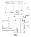
- residencessuch as houses, apartments, and condominiums have multiple types of wires for power and/or communications.
- a housemay typically have one or more ring mains, or may have multiple spurs configured to supply power to most, if not all, of the rooms in the house.
- the housemay additionally have one or more telephone line connections, including multiple extensions accessible in various rooms.
- the telephone linemay provide telephone communications and/or Internet access using a digital subscriber line (DSL) standard.
- DSLdigital subscriber line
- Many homesadditionally have one or more coaxial cable connections to a number of rooms. For example, cable television programming or satellite television programming, or terrestrial analog television may be received via the coaxial cable.
- the phone line or coax in the homemay be unused by any apparatus. Further, networked apparatuses may communicate via Ethernet cabling.
- a television setmay communicate with a digital versatile disc (DVD) player to display a movie on the television set.
- DVDdigital versatile disc
- These communicationsrequire separate wires and/or cables connecting the DVD player to the television set.
- These device-to-device wirescan become very complex, if, for example, other components such as a stereo system are also connected to the television set. Further, the stereo system may be separately connected via another wire to a personal computer or media player.
- the use of a dedicated wire between devicesadditionally limits which devices are able to communicate with one another. For example, many homeowners are reluctant to connect a very long wire from, for example, a television in the kitchen to a DVD player in a bedroom.
- Powerline communicationis a technology that encodes digital data in a signal and transmits the signal on existing electricity powerlines in a band of frequencies that are not used for supplying electrical power. Accordingly, PLC leverages the ubiquity of sockets within existing power supply networks to provide an extensive number of possible connection points to form a network.
- a powerline network in a household 100typically has a distributed mains wiring system consisting of one or more ring mains, several stubs or spurs and some distribution back to a junction box 104 .
- the household 100is supplied electrical power from an external line 102 .
- the junction box 104routes the electrical power among ring mains 106 , 108 , and 110 .
- the household 100further comprises a telephone line network 112 .
- the telephone line network 112does not require a junction box or division among multiple rings. It should be noted that the powerline network is typically more widely distributed to outlets and rooms than the telephone line network 112 .
- the outlets most closely located to each otherare those on multi-plug strips, and the outlets furthest away from each other are those on the ends of stubs of different ring mains (e.g. power outlets in the first floor and the second floor). Communications between these furthest outlets typically pass through the junction box 104 . In some PLC systems, it may be difficult to pass communications through the junction box, particularly if they are on different alternating current (AC) phases.
- ACalternating current
- a communications device for simultaneous multi-wideband communications over multiple mediumsmay include, for example, a powerline, a telephone line, and/or a coaxial cable.
- a communicationmay be transmitted or received via any of the mediums.
- a communicationmay be received via a first medium and forwarded in a second medium.
- a third mediummay also be available for reception and/or transmission of the communication.
- a multi-network interface devicemay receive a communication via a powerline and forward the received communication via a telephone line.
- a communication between two multi-network interface devicesmay be transmitted, in parallel or sequentially, through two or more mediums within a communications network.
- a video signalmay be transmitted from a DVD player to a television via both the powerline and a coaxial cable.
- one mediummay be used to bridge two portions of another medium.
- a telephone linemay be used as a bridge between sections of mains cable or sections on different AC phases in a powerline network.
- the various mediamay be used in conjunction with multi-wideband communications.
- the multi-widebandsinclude, for example, a lower frequency range below approximately thirty megahertz and a higher frequency range above approximately thirty megahertz. In some embodiments, the lower frequency range is between two megahertz and twenty-eight megahertz while the higher frequency range is between fifty megahertz and three hundred megahertz.
- the lower frequency bandmay be conducted via the powerline, and the higher frequency band may be conducted via the powerline and/or another medium such as a telephone wire or coax cabling.
- a single mediamay be used for communications using both lower and higher frequency ranges.
- higher frequency signalsmay be moved to another frequency range by mixing, for example to take the signal to above an existing service on the wire, such as in the case of a coaxial cable that already caries analog or digital television information.
- the higher frequency bandmay be moved, for example, between 1.2 gigahertz and 1.45 gigahertz or between 1.55 gigahertz and 1.8 gigahertz.
- a portion of the higher frequency bandmay be above 2 gigahertz.
- a signal in the higher frequency bandsmay comprise an ultra-wideband signal at least 500 megahertz wide.
- the single reference designis optionally a single unit that comprises filters and other components configured to enable connection to different mediums and passing the communications over these mediums.
- the single reference designmay comprise multiple interfaces configured to communicate over telephone line, powerline, and/or coaxial cable.
- the single reference designmay further allow the different mediums to share a single media access control (MAC) address.
- the single reference designmay be powered via the powerline communications interface.
- communicationsmay be received and/or transmitted using powerlines and either telephone lines or coaxial cables.
- the single reference designmay comprise a single host interface controller configured to communicate with a networked apparatus.
- a powerline communications devicecomprises a powerline communications interface, a second communications interface, and a processor.
- the powerline communications interfaceis configured to transmit a message via a powerline.
- the second communications interfaceis configured to transmit the message via a second medium.
- the processoris configured to determine, in the alternative, whether to transmit the message via the powerline or the second communications interface based on a quality of service metric associated with the powerline network.
- a powerline communications devicecomprises a network processor and a host interface controller.
- the network processorcomprises logic configured to determine whether to alternatively communicate a message via a powerline communications interface or a second communications interface, the second communications interface being configured to communicate via a telephone line or a coaxial cable, both the powerline communications interface and the second communications interface being associated with a same media access control address.
- the host interface controlleris configured to be shared by communications received through the powerline communications interface and the second communications interface.
- a networkcomprises a first section of mains cable configured to provide AC power, a second section of mains cable configured to provide AC power and connected to the first section of mains cable via a junction box, a telephone network, a first device configured to receive a message via the first section of mains cable and forward the message via the telephone network, and a second device configured to receive the message from the first device via the telephone network, and to forward the message via the second section of mains cable.
- a methodcomprises generating a message; transmitting the message via a first section of mains cable connected to a second section of mains cable via a junction box; receiving the message at a first device; transmitting the message from the first device, via a telephone line or a coaxial cable; receiving the message from the first device, at a second device; and transmitting the message from the second device, via the second section of mains cable.
- a networkcomprises a first section of mains cable configured to provide AC power, a second section of mains cable configured to provide AC power and connected to the first section of mains cable via a junction box, a coaxial cable network, a first device configured to receive a message via the first section of mains cable and forward the message via the coaxial cable network, and a second device configured to receive the message from the first device via the coaxial cable network, and to forward the message via the second section of mains cable.
- FIG. 1is a diagram of a prior art household
- FIG. 2Ais a diagram of an exemplary multi-network interface device comprising a plurality of interfaces for communicating over various mediums, according to various embodiments;
- FIG. 2Bis a diagram of an exemplary embedded multi-network interface device comprising a plurality of interfaces for communicating over various mediums, according to various embodiments;
- FIG. 2Cis a diagram of an exemplary multi-network interface device connected to a network apparatus, according to various embodiments.
- FIG. 3includes exemplary communications transmission spectra of three mediums, according to various embodiments
- FIG. 4is a block diagram of a first circuit embodiment of the multi-network interface device, according to various embodiments.
- FIG. 5is a block diagram of a second circuit embodiment of the multi-network interface device, according to various embodiments.
- FIG. 6is a block diagram of a third circuit embodiment of the multi-network interface device, according to various embodiments.
- FIG. 7is a block diagram of a fourth circuit embodiment of the multi-network interface device, according to various embodiments.
- FIG. 8is a block diagram of a fifth circuit embodiment of the multi-network interface device, according to various embodiments.
- FIG. 9depicts the frequency characteristics of a frequency band associated with the signal used by the fifth integrated circuit embodiment depicted in FIG. 8 , according to various embodiments;
- FIG. 10is a block diagram of a sixth circuit embodiment of the multi-network interface device, according to various embodiments.
- FIG. 11is a block diagram of a seventh circuit embodiment of the multi-network interface device, according to various embodiments.
- FIG. 12is a block diagram of an eighth circuit embodiment of the multi-network interface device, according to various embodiments.
- FIG. 13is a flowchart depicting an exemplary method for communicating within a network, according to various embodiments.
- FIG. 14is a flowchart depicting an exemplary method for bridging between mediums, according to various embodiments.
- powerlinewill be used herein to refer to low voltage household or commercial mains distribution cabling (typically 100-240 V AC power) or any other distributed electrically conductive AC cabling that is capable of passing power to appliances connected to it.
- powerline technologywill be used herein to refer to a specification that when implemented as a series of network interface devices connected to a powerline, enables the devices to bi-directionally communicate with each other using signals superimposed on the power distribution AC voltages also present on the powerline.
- multi-network interface devicewill be used herein to describe an apparatus that implements either fully or partially, at least two communications technologies, such as a powerline technology, a telephone line technology, or a coaxial cable technology to enable the apparatus to communicate with other devices connected via the same communications technology (such as a powerline, telephone line, or coaxial cable) to a network, regardless of whether or not the apparatus is integrated with other apparatuses or functions within a single enclosure.
- the multi-network interface devicemay be a powerline communications device having additional communications interfaces for communicating via a phone line and/or a coaxial cable.
- a frequency band used in the multi-network interface devicecomprising a frequency of less than about 30 MHz, will be known herein as a “low band(s)”.
- a frequency band(s) used in the powerline communication devices, telephone line communications devices, and coaxial cable communications devices whose frequency is greater than about 30 MHzwill be known herein as “high band(s).”
- signal pathwill be used to refer to the path of a signal transmitted or received from a network apparatus to the powerline, telephone line or coaxial cable.
- Frequency bandsare to characterize frequency bands that do not use, except incidentally, the same frequencies for communication data or commands.
- Frequency bandsmay be separate but interleaved, e.g., overlapping.
- simultaneousis used herein with respect to communicating data to indicate that at least part of first data or commands are communicated using a first frequency band and/or medium at the same time as at least part of second data or commands are communicated using a second frequency band and/or medium.
- simultaneous transmissionis contrasted with systems that alternate or interleave the use of frequency ranges, one frequency range after the other or hopping from one frequency range to the other frequency range while not using both frequency ranges at the same moment.
- independentis used herein with respect to data transmitted to indicate that data transmitted using one frequency band does not depend on data transmitted using another frequency band.
- Independent data transmissioncan include, for example, data sent to or received from different locations.
- Data in which alternative bits are transmitted using different frequenciesis not independent because the bits are dependent on each other to form a useful byte.
- Data transmitted in a first frequency band and including communication setup information, decryption keys, communication commands, or the likeis considered independent from data sent in a second frequency band, even when the receipt or processing of the data sent in the second frequency band may use the data in the first frequency band. This is because, transmission of the communication setup information, decryption keys, communication commands, or the like does not depend on the data sent in the second frequency band.
- widebandis used herein to refer to a frequency band or range used by a powerline, telephone line, or coaxial cable technology signal, characterized by having a bandwidth of greater than, or equal to, about 5 MHz from the first (lowest) frequency to the last (highest) frequency of the band irrespective of the presence of notches.
- widebandmay have bandwidths of at least 5, 7, 10, 12, 15, 20, 100, 250 or 500 MHz.
- a widebandmay include many different carrier channels used to convey data.
- widebandsinclude more than 25, 50, 100, 250, 500, or 1000 data carrier frequencies with or without CDMA sequences.
- Various embodiments of the inventionmay make use of wide or narrow frequency bands.
- section of mains cableis used herein to refer to various sections of cabling in a typical AC electrical wiring system in a home or building or dwelling.
- the various sectionsmay be separated from each other by the electrical distribution means, such as a junction box, fuse box, surge protector, residual current detector, or the like.
- An individual section of mains cablemay be on a different AC phase than other sections of mains cable within the dwelling.
- the section of mains cablemay comprise two or three core class cables with or without shielding.
- the AC electrical wiring systemmay transfer electricity having a voltage of approximately 110 Volts, 240 Volts, or other standard voltage levels.
- the section of mains cablemay comprise, at least in part, a ring main or loop.
- the section of mains cablemay comprise, at least in part, a spur that may be part of a branch-based arrangement.
- Some embodiments of the communications networkcomprise a plurality of nodes of which some employ a multi-network interface device that enables simultaneous and/or independent communication over two or more mediums.
- a first frequency bandoptionally comprises frequencies of less than 30 MHz and the other frequency band(s) comprise frequencies of greater than 30 MHz.
- both a first and a second frequency bandmay comprise frequencies greater than 30 MHz. Because of the multiple frequency bands can be in different ranges, communications can be optimized for each of the mediums such that the trade-off between cost, coverage, and throughput will be superior to that achieved by a network comprising a single medium.
- the computing networkcomprising powerlines, telephone lines, and/or coaxial cable provides inter-operability with prior art powerline technologies by also supporting communication between multi-medium nodes and single medium nodes (that communicate via a single medium (e.g. powerline).
- a single mediume.g. powerline
- the multi-network interface devicemay be part of an external modem apparatus or embedded within another apparatus (e.g. computer, television, etc.). However, regardless of the manner in which the multi-network interface device is included within a network node, the device remains connected to electrically conductive cabling (that passes AC power) and is capable of transmitting data across the cabling using the low and/or high bands. Further, the multi-network interface device is capable of communicating over more than one medium (e.g. telephone line, coaxial cable, or powerline).
- mediume.g. telephone line, coaxial cable, or powerline
- the multi-network interface devicetypically employs an analog signal separation device configured to isolate data communication paths from AC power transmission, prior art telephone line communication, and/or prior art coaxial cable communication, to an apparatus.
- an analog signal separation deviceconfigured to isolate data communication paths from AC power transmission, prior art telephone line communication, and/or prior art coaxial cable communication, to an apparatus.
- One of the most efficient ways of providing this isolationis by high-pass filtering or band-pass filtering whilst minimizing out-of band signals in the low band.
- high band signalsmay be filtered using high linearity components and low band signals may be filtered using analog low-pass smoothing or anti-aliasing. It may not be necessary to perform the isolation on both receiver and transmitter signal paths (depending on the specifications of the analog components and the modulation techniques employed therein).
- Signals in the high band and the low bandcan use the same or different modulation techniques (e.g. Orthogonal Frequency Division Multiplexing (OFDM), and/or Code Division Multiple Access (CDMA)) or time division schemes to facilitate co-existence and/or bi-directional communication.
- OFDMOrthogonal Frequency Division Multiplexing
- CDMACode Division Multiple Access
- the low bandemploys a modulation scheme that is inter-operable with one of the existing powerline modem standards or proposals, whilst the high band on the powerline is used for performance expansion beyond previous standards or in other mediums.
- Data and/or control commandscan be passed through one or both of the mediums simultaneously and via a plurality of multi-network interface devices in the form of a repeater (e.g., relay) network.
- a repeatere.g., relay
- different types of signalsare communicated in different frequency bands.
- communication setup information, node discovery signals, path discovery signals, encryption or decryption keys, communication commands, and/or other types of command and control signalsare communicated in a first frequency band while other types of data (e.g., non-command and control) are communicated in a second frequency band.
- the other types of data communicated in the second frequency bandmay include video, audio, and/or text, etc.
- FIG. 2Ais a diagram of an exemplary multi-network interface device 200 comprising a plurality of interfaces for communicating over various mediums.
- the exemplary multi-network interface device 200may be a separate device, such as an adapter, or embedded into a network apparatus such as a television, stereo, DVD player, personal computer, or the like.
- the multi-network interface device 200may comprise one or more communications interfaces including a phone line interface 202 , a powerline interface 204 , and/or a coaxial cable interface 206 .
- the communications interfacesare each configured to communicate over their respective mediums.
- the multi-network interface device 200may further comprise one or more interfaces for communication with an apparatus connected to the multi-network interface device 200 .
- the multi-network interface device 200comprises a second set of communications interfaces including a second phone line interface 208 and an Ethernet interface 210 configured to connect to telephone and an Ethernet network apparatus, respectively.
- the single reference designis optionally a single device that comprises filters and other components configured to enable connection to different mediums and passing the communications over these mediums.
- the single reference designmay comprise multiple interfaces configured to communicate over telephone line, powerline, and/or coaxial cable.
- the single reference designmay further allow the different mediums to share a single media access control (MAC) address.
- the single reference designmay be powered via the powerline communications interface.
- the single reference designmay comprise a single host interface controller configured to be shared by communications using the various mediums.
- the telephone interface 202is configured to communicate over a telephone line network.
- the telephone interfacemay, in addition to communicating high band signal(s), simultaneously communicate voice signals, DSL signals (including ADSL and VDSL signals), Home Phoneline Networking Alliance (HPNA)-compatible signals, and/or the like. Additionally, the telephone line may already carry these types of signals generated by other sources in other locations.
- DSL signalsincluding ADSL and VDSL signals
- HPNAHome Phoneline Networking Alliance
- the powerline interface 204may comprise an interface configured to receive electrical power via a powerline.
- the powerline interface 204may comprise a male and/or female connector.
- the coaxial cable interface 206is configured to communicate via a coaxial cable network.
- the coaxial cable interfacemay, in addition to communicating high band communication signal(s), also communicate DSL signals, Data Over Cable Service Interface Specification (DOCSIS)-compatible signals, television broadcast signals (including cable television and/or digital television signals), Multimedia over Coax Alliance (MoCA)-compatible signals, Satellite L-Band signals, and/or the like. Additionally, the coaxial cable may already carry these types of signals generated by other sources in other locations.
- DOCSISData Over Cable Service Interface Specification
- MoCAMultimedia over Coax Alliance
- the second telephone interface 208is configured to communicate a signal between the multi-network interface device 200 and a device.
- the second telephone interface 208may communicate with a telephone or a DSL modem.
- the multi-network interface device 200may comprise a second coaxial cable interface 206 and/or a second powerline interface 204 .
- Second telephone interface 208may be connected to a telephone and be used to communicate a telephone call.
- the Ethernet interface 210is one example of a host interface and is configured to communicate a signal between the multi-network interface device 200 and a device configured to communicate over an Ethernet connection.
- the Ethernet interfacemay, for example, be connected to a personal computer, media player, or WiFi modem.
- the Ethernet interface 210may be part of a device compatible with the Universal Plug'n Play (UPnP) standard, Digital Living Network Alliance (DLNA) standard, or the like.
- UFPUniversal Plug'n Play
- DLNADigital Living Network Alliance
- the communications signalmay travel on one or more of the mediums to reach the multi-network interface device 200 from another node on the network.
- the multi-network interface device 200may be configured to determine the medium on which to transmit the communications signal based on a Quality of Service (QoS) metric associated with each medium.
- QoSQuality of Service
- the QoS metricmay measure network latency, network throughput, available bandwidth, or the like.
- the multi-network interface device 200may vary which medium is used to transmit signals if the QoS metric changes over time.
- Signalsare received at one of the interfaces (telephone line interface 202 , the powerline interface 204 , the coaxial cable interface 206 , the second telephone line interface 208 , and/or the Ethernet interface 210 ) where they may be filtered, converted, frequency shifted, modulated, mixed, or otherwise modified the signal to generate a desirable output signal.
- the output signalmay be transmitted via any of the interfaces including the telephone line interface 202 , the powerline interface 204 , the coaxial cable interface 206 , the second telephone line interface 208 , and/or the Ethernet interface 210 .
- the multi-network interface device 200is associated with a single media access control (MAC) address. That is, communications received via any of the mediums may be addressed to the same MAC address.
- the multi-network interface device 200may be associated with two or more MAC addresses and/or have two or more Ethernet interfaces 210 .
- the multi-network interface device 200may comprise a router and routing table, a switch, or the like.
- the signalmay substantially “pass through” the communication device 200 .
- the multi-network interface device 200may be connected to the telephone line via the telephone line communications interface 202 .
- the telephone line communications interface 202may be connected to the telephone line via the telephone line communications interface 202 .
- a homeownermay wish to install a telephone in the same telephone line connection.
- the homeownermay install the multi-network interface device 200 while still being able to use the same telephone line connection for a telephone.
- FIG. 2Bis a diagram of an exemplary apparatus 212 comprising an embedded multi-network interface device 200 having a plurality of interfaces for communicating over various mediums, according to various embodiments.
- the apparatus 212comprises the multi-network interface device 200 , a host subsystem 214 , a host interface 216 , and an apparatus interface 218 .
- the apparatus 212may comprise a network apparatus such as a set top box, a DSL Home Gateway, a television set, a DVD player, a kitchen appliance (e.g. a refrigerator, microwave, stove, oven, etc.), a wireless access point, a computing device, a data storage device, a stereo, or the like.
- the host subsystem 214comprises the prior art hardware and/or software included in the network apparatus, e.g., the television receiver or the DVD reader.
- the host interface 206comprises a communications interface between the multi-network interface device 200 and host subsystem 214 .
- the apparatus interface 218is an output or input of the host subsystem 214 as known in the prior art.
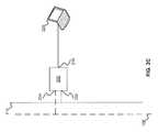
- FIG. 2Cis a diagram of an exemplary multi-network interface device 200 connected to a separate network apparatus 220 .
- the multi-network interface device 200is connected to a powerline 106 and a telephone line 112 , via the powerline interface 204 and the telephone line interface 202 , respectively.
- the multi-network interface device 200is also connected to the network apparatus 220 via a host interface 216 to the network apparatus 220 .
- One example of the host interface 216is the Ethernet interface 210 .
- the network apparatus 220comprises a laptop computer.
- the network apparatus 220may comprise a set top box, a DSL Home Gateway, a television set, a DVD player, a kitchen appliance (e.g. a refrigerator, microwave, stove, oven, etc.), a wireless access point, a computing device, a data storage device, a stereo, or the like.
- the host interface 216is configured to communicate directly with a network apparatus and to act as a first interface between the network apparatus and the rest of the network. In comparison with other interfaces of the multi-network interface device 200 , the host interface 216 is optionally connected to just the network apparatus 220 rather than a network including multiple devices and/or mediums. Typically, the host interface 216 is configured to provide communications between the network apparatus 220 and the multi-network interface device 200 over a single medium. As is illustrated in FIGS. 2B and 2C , the host interface 216 may be embedded within an apparatus 212 or may be an interface between the separate devices (e.g., multi-network interface device 200 and the network apparatus 220 ).
- the host interface 216is one example of a “host interface.”
- a host interfacemay be a boundary between two entities that exchange data using Ethernet class II packets and interfaces associated with a direct application endpoint or start point.
- Ethernet class II packetsinclude IEEE 802.3 packets with or without IEEE 802.2 (Logical Link Control (LLC)), IEEE 802.1H (Sub Network Access Protocol (SNAP)) extensions and/or Virtual Local Area Network (VLAN) tagging.
- LLCLogical Link Control
- SNAPSub Network Access Protocol
- VLANVirtual Local Area Network
- host interface 216examples include: Ethernet 10/100/1000, Media Independent Interface (MII), Gigabit Media Independent Interface (GMII), Peripheral Component Interconnect (PCI), Host Processor Interface, Universal Serial Bus (USB) 2.0, Firewire, Peripheral Component Interconnect Extended (PCI-X), Peripheral Component Interconnect Express (PCIe), Universal Asynchronous Receiver Transmitter (UART), Service Provider Interface (SPI), or the like.
- MIIMedia Independent Interface
- GMIIGigabit Media Independent Interface
- PCIPeripheral Component Interconnect
- USBUniversal Serial Bus
- FirewirePeripheral Component Interconnect Extended
- PCIePeripheral Component Interconnect Express
- UARTUniversal Asynchronous Receiver Transmitter
- SPIService Provider Interface
- Examples of host interface 216 associated with a direct application end point or start pointinclude: Serial Advanced Technology Attachment (SATA) I/II/III, Universal Serial Bus (USB) 2.0, Inter-Integrated Circuit Sound (I2S), Universal Asynchronous Receiver Transmitter (UART), Infrared Data Association (IrDA) protocols, Moving Picture Experts Group (MPEG) Transport Stream (TS), High-Definition Multimedia Interface (HDMI), and Video Graphics Array (VGA).
- SATASerial Advanced Technology Attachment
- USBUniversal Serial Bus
- I2SInter-Integrated Circuit Sound
- UARTUniversal Asynchronous Receiver Transmitter
- IrDAInfrared Data Association
- MPEGMoving Picture Experts Group
- TSTransport Stream
- HDMIHigh-Definition Multimedia Interface
- VGAVideo Graphics Array
- FIG. 3includes exemplary communications transmission spectra of three mediums, according to various embodiments. Any or all of the mediums (powerlines, telephone lines, and/or coaxial cable) may be present in a network.
- the various frequency bands depicted in FIG. 3may comprise widebands and/or narrow bands.
- Other, different, communications spectramay be used in alternative embodiments.
- the x-axisrepresents frequency.
- a communications transmission spectrumas may be associated with a powerline is shown.
- the spectrum 302comprises a low band 304 and a high band 306 .
- the low band 304may comprise frequency bands below approximately thirty megahertz.
- the low band 304may include base band powerline communications frequencies as described in the HomePlug AV standard (i.e. two megahertz to thirty megahertz).
- the high band 306comprises one or more frequency bands above approximately thirty megahertz (e.g. fifty megahertz to three hundred megahertz).
- the high band 306may comprise a frequency band above one gigahertz.
- use of the high band 306is optional. Communications signals may be transmitted on the powerline in both the low band 304 and the high band 306 simultaneously and/or independently.
- a communications transmission spectrumas may be associated with a telephone line is shown.
- the spectrumcomprises a lower frequency band 310 on which communications of the prior art are transmitted. These communications include voice telephony, ADSL, VDSL, HPNA, and the like.
- the high band 306used in powerline communications, may also be used on the telephone line.
- a frequency band 314is currently associated with DSL standards and DOCSIS.
- a frequency band 316is associated with television broadcasts, cable television, and digital television.
- Frequency band 318is associated with the MoCA standard and the Satellite L-Band between three hundred ninety megahertz and 1.55 gigahertz.
- the communication signal associated with a home networkis transmitted at a higher frequency than the satellite L-band, namely, above 1.55 gigahertz, in a high band 320 .
- the high band 320may be associated with a bandwidth of approximately two hundred fifty megahertz.
- a service providercan fully exploit the L-band without interference caused by the home network.
- placing the high band 320 above the other frequencies used by a service providermay reduce the likelihood that content, such as downloaded films or television shows, provided by the service provider may be hacked or otherwise stolen by a homeowner.
- the communication signal associated with the home networkis communicated at least partially within the L-band in high band 324 .
- the high band 324ranges from approximately one gigahertz to approximately 1.5 gigahertz.
- the high band 324may range from approximately 1.2 gigahertz and 1.45 gigahertz.
- the high band 324may use frequencies not lower than 1.1 gigahertz, 1.2 gigahertz, 1.3 gigahertz, 1.4 gigahertz, 1.5 gigahertz, 1.6 gigahertz, 1.7 gigahertz, 1.8 gigahertz, 1.9 gigahertz and 2.0 gigahertz.
- Frequency ranges included in some embodimentsare described in nonprovisional U.S. patent application Ser. No. 11/536,539 filed Sep. 28, 2006 and entitled “Multi-Wideband Communications over Powerlines.”
- the signal transmit in frequency band 318 and/or the signal transmit in high band 324may be encrypted or otherwise protected.
- frequency band 316 associated with television broadcasts, cable television, and digital televisionis not being used, the communication signal associated with the home network is communicated at least partially within frequency band 328 .
- At least a portion of the frequency band 328includes frequencies between 50 MHz and 300 MHz.
- FIGS. 4-8 and 10 - 12depict various embodiments of multi-network interface device 200 .
- the depicted embodimentssupport communications via a powerline and a telephone line, and via a powerline and a coaxial cable. It is understood that these embodiments may be modified by those skilled in the art to support communications over any combination of the three mediums.
- a multi-network interface device 200may support communications via a telephone line and a coaxial cable, but not a powerline.
- the embodiments shownmay comprise one or more integrated circuit.
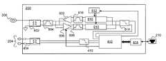
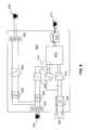
- FIG. 4is a block diagram of a first circuit embodiment of the multi-network interface device 200 .
- the multi-network interface device 200is configured to provide communications interfaces for a powerline and a telephone line.
- a communicationmay be received and/or transmitted via the telephone line interface 202 and/or the powerline interface 204 .
- the telephone lineis passively shared with prior art telephone signals.
- the multi-network interface device 200processes a communications signal received through the telephone line interface 202 and/or powerline interface 204 and provides a resulting output signal via an optional Ethernet interface 210 , and vice-versa.
- Ethernet interface 210is optionally coupled to a network apparatus such as a television set, DVD player, media player, personal computer, speaker, stereo, video game console, personal digital assistant, or the like.
- the multi-network interface device 200may receive the communications signal from one of the telephone line interface 202 or the powerline interface 204 and transmit the communications signal via the other telephone line interface 202 or the power-line interface 204 .
- the telephone linemay be used to provide redundancy in a mesh or ad-hoc network.
- a signalis communicated via the telephone line interface 202 . These signals may be communicated in the high band 306 .
- the signal path from the telephone line interface 202 to the Ethernet interface 210comprises a surge protector 402 , an inductive coupler 404 , a high pass filter 406 , a network processor 412 , and a host interface controller 414 .
- the high pass filter 406may allow only frequencies above approximately thirty megahertz to pass.
- the surge protector 402 , the inductive coupler 404 , and the high pass filter 406collectively provide signal communications without significantly impacting services existing on lower frequencies.
- a signalis communicated via the powerline interface 204 .
- the signalmay be communicated via the low band 304 and/or the high band 306 .
- the signal path from the powerline interface 204 to the Ethernet interface 210comprises an inductive coupler 408 , and, depending on the frequency band of the signal, the high pass filter 406 and/or a low pass filter 410 .
- the inductive coupler 408 , the high pass filter 406 and the low pass filter 410collectively provide signal communications without significantly impacting prior art signals at lower frequencies.
- the powerline interface 204may not be configured to communicate via the high band 306 . In these embodiments, the high pass filter 406 is optional.
- the network processor 412 and the host interface controller 414are shared by the signal paths associated with the powerline interface 204 and the telephone line interface 202 .
- the network processor 412comprises processing circuitry to remove noise, amplify the signal, and/or convert an analog signal to a digital signal or vice-versa.
- the network processor 412may comprise two or more analog front ends (AFE). One of the AFEs is configured to receive and/or transmit a communications signal on the high band 206 and the other of the AFEs is configured to receive and/or transmit a communications signal on the low band 304 .
- a communication signal received via the high band 306passes through the high pass filter 406 and a high frequency AFE 416
- a communication signal received via the low band 304passes through the low pass filter 410 and a low frequency AFE 418 .
- the network processor 412may further comprise a line driver, programmable gain amplifier, an analog-to-digital converter, and/or a digital-to-analog converter. Possible configurations of the network processor 412 are described in greater detail in nonprovisional U.S. patent application Ser. No. 11/536,539 filed Sep. 28, 2006 and entitled “Multi-Wideband Communications over Powerlines.” Logic within the network processor may determine whether to transmit a communication signal via a certain communications interface based on a quality of service metric of the communications network or a purpose of the communication signal.
- the network processor 412may be compatible with the HomePlug AV standard or other standards associated with powerline communications, telephone line communications, or coaxial cable communications.
- Network processor 412is optionally configured to process prior art telephone signals, e.g., if the multi-network interface device 200 is included in a telephone.
- the host interface controller (ICONT) 414allows for communication of data between the Ethernet interface 210 and the network processor 412 .
- the ICONT 414may implement an Ethernet controller as specified by IEEE 802.3.
- the ICONT 414includes the Physical and Data Link layers as defined in the seven layer OSI reference model for standardizing computer-to-computer communications.
- ICONT 414may implement a TCP/IP stack that includes the Network, Transport and Application layers of the OSI reference model.
- the multi-network interface device 200may receive power via the powerline interface 204 .
- ICONT 414is optionally included within network processor 412 , host interface PCI driver, or the like.
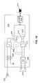
- FIG. 5is a block diagram of a second embodiment of the multi-network interface device 200 .
- the multi-network interface device 200is configured to communicate a first signal via the low band 304 over a powerline and to communicate a second signal via the high band 306 over a telephone line.
- the multi-network interface device 200additionally comprises a second telephone line interface 208 .
- the second telephone line interface 208may be used to communicate voice, ADSL, VDSL, or HPNA signals within band 310 .
- an optional second inductive coupler 502may be placed between the surge protector 402 and the inductive coupler 404 .
- the second inductive coupler 502is coupled to an optional low pass filter 504 to isolate the signal within the band 310 from other communications signals communicated within the high band 306 .
- the low pass filter 504may pass frequencies below approximately thirty megahertz.
- Another surge protector 402may be placed between the low pass filter 504 and the second telephone line interface 208 .
- a usermay connect a non-network apparatus such as a telephone, DSL modem, or the like to the second telephone line interface 208 .
- the first telephone line interface 202 and the second telephone line interface 208are connected by a direct pass-through connection.
- FIG. 6is a block diagram of a third embodiment of a multi-network interface device 200 .
- the multi-network interface device 200is configured to communicate a first signal via the low band 304 over a powerline, to communicate a second signal via the high band 306 over the powerline, and optionally to communicate the second signal or a third signal via the high band 306 over a telephone line.
- the multi-network interface device 200comprises a second telephone interface 208 from which a fourth signal, in band 310 , may be communicated as discussed in connection with FIG. 5 .
- the multi-network interface device 200comprises a network processor 412 having a single high frequency AFE 416 configured to receive or transmit signals communicated via the high band 306 over both the powerline and the telephone line.
- the single high frequency AFE 416optionally includes passive sharing of the powerline and the phone line. As such, the single high frequency AFE 416 can only receive or only transmit one signal at any one time.
- FIG. 7is a block diagram of a fourth embodiment of the multi-network interface device 200 .
- the embodiment of multi-network interface device 200 illustrated in FIG. 7is substantially similar to the multi-network interface device 200 illustrated in FIG. 6 except for a dual high frequency AFE 702 .
- the dual high frequency AFE 702includes two separate inputs configured to independently and simultaneously communicate signals in the high band 306 and through both the telephone line interface 202 and the powerline interface 204 .
- FIG. 8is a block diagram of a fifth embodiment of the multi-network interface device 200 .
- the multi-network interface device 200is configured to communicate between an optional Ethernet interface 210 , a powerline interface 204 , and a coaxial cable interface 206 .
- the communicationmay pass between any two or all three of these interfaces.
- the multi-network interface device 200may communicate over a powerline using the low band 304 and over coaxial cable using either band 320 or band 324 .
- the powerline signal pathmay be configured to support communications over the high band 306 .
- the multi-network interface device 200may support communications between the power line interface 204 and the coaxial cable interface 206 .
- the signal path from the powerline interface to the Ethernet interface 210is further discussed herein, for example, in connection with FIG. 4 .
- the signal path from the coaxial cable interface 206comprises an inductive coupler 802 , a band pass filter 804 , a receiving signal path, and transmitting signal path, a local oscillator 812 , a low pass filter 814 , the network processor 412 , and the ICONT 414 . From the ICONT 414 , the signal may be communicated to the Ethernet interface 210 and/or the powerline interface 204 .
- the receiving signal pathcomprises a low noise amplifier 806 , a band pass filter 808 , and an optional down converter mixer 810 .
- the transmitting signal pathcomprises an optional up converter mixer 816 , a band pass filter 818 , and a programmable amplifier 820 .
- the network processor 412 and the ICONT 414may be shared with the powerline signal path.
- the coaxial cablemay carry signals at frequencies above one gigahertz, as described herein, for example, in connection with FIG. 3 .
- the network processor 412may be configured to process signals having frequencies within low band 304 and high band 306 . Therefore, these signals may be shifted between the high band 306 and the high band 320 or the high band 324 along the coaxial cable signal path using the up converter mixer 816 or the down converter mixer 310 , respectively.
- clock error on the coaxial cablemay be communicated over the powerline using the powerline interface 204
- the inductive coupler 802 and the band pass filter 804collectively enable signal communications without impacting prior art services on lower frequencies.
- the low-noise amplifier 806may amplify a signal received via the coaxial cable interface 206 based on a control signal received from the network processor 412 .
- the signalmay then pass through an optional second band pass filter 808 before entering the down converter mixer 810 .
- the down converter mixer 810is controlled by the local oscillator 812 , which is, in turn, controlled by the network processor 412 .
- the down converter mixer 810is configured, based on the received signal, to generate two lower frequency sidebands.
- the low pass filter 814passes one of the two lower frequency sidebands. The passed lower frequency sideband is then processed by the network processor 412 .
- An output signal from the network processor 412 via the coaxial cable interface 206optionally passes through the low pass filter 814 , the up converter mixer 816 , a band pass filter 818 , and a programmable gain amplifier 820 .
- the up converter mixer 816is controlled by the local oscillator 812 and generates two side bands.
- the band pass filter 818isolates one of the sidebands for transmission via the coaxial cable.
- the isolated sidebandmay be selected based on the presence or absence of satellite L-band signals on the coaxial cable.
- the isolated sidebandis then amplified by programmable amplifier 820 .
- the signalpasses through the band pass filter 804 and the inductive coupler 802 upon leaving the transmission path.
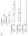
- FIG. 9depicts frequency bands associated with the signal used by the fifth integrated circuit embodiment 200 depicted in FIG. 8 , according to various embodiments when the signal is communicated via the coaxial cable.
- Spectra 902 , 904 , and 906depict frequency characteristics of a signal received by the multi-network interface device 200 along the receiving signal path.
- Spectra 908 , 910 , and 912depict frequency characteristics of the signal transmitted by the multi-network interface device 800 along the transmitting signal path.
- the signalsare communicated via the coaxial cable using high band 324 . In other embodiments, the signals may be received and/or transmitted over high band 320 .
- a signal within the high band 324is received by the coaxial cable interface 206 .
- the down converter mixer 810generates two sidebands, in the high band 306 and in another band 914 , based on the received signal as depicted in spectra 904 . At least one of these sidebands may be within high band 306 or low band 304 .
- the lower frequency sidebandis shown to be within high band 306 .
- the low pass filter 814isolates the sideband in high band 306 shown in spectrum 906 , which can be processed by network processor 412 .
- the network processor 412To transmit a signal via the coaxial cable interface 206 , the network processor 412 generates the signal in the high band 306 , as shown in spectrum 908 .
- the up converter mixer 816generates two side bands from the generated signal as shown in spectrum 910 . In the embodiment shown, at least one of these sidebands is within high bands 320 and 324 as described herein, at least, in connection with FIG. 3 . Other embodiments may generate sidebands in other frequencies.
- the sideband, e.g. in band 324to be transmitted via the coaxial cable interface 206 is isolated, as shown in spectrum 912 , using the band pass filter 818 .
- network processor 412is configured to directly process and/or generate signals in the high band 324 and/or the high band 320 .
- the multi-network interface device 200may comprise a communications interface is associated with a second media access control address.
- the multi-network interface device 200may comprise a router or switch. The router may access a router table to route communications and/or messages to an appropriate MAC address.
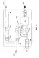
- FIG. 10is a block diagram of a sixth circuit embodiment of the multi-network interface device 200 , according to various embodiments.
- the multi-network interface device 200is configured to communicate between an optional host interface 216 , a powerline interface 204 , and a coaxial cable interface 206 .
- the multi-network interface devicemay communicate via the powerline and/or the host interface 216 as described herein, at least, in connection with FIG. 4 .
- the coaxial cable interface 206may communicate signals within the frequency band 328 described herein, at least, in connection with FIG. 3 .
- the high pass filter 406may isolate the signals in frequency band 328 from those present on the coaxial cable in band 314 .
- FIG. 11is a block diagram of a seventh circuit embodiment of the multi-network interface device 200 , according to various embodiments.
- the multi-network interface device 200is configured to communicate between an optional host interface 216 , a powerline interface 204 , and a coaxial cable interface 206 .
- the multi-network interface devicemay communicate via the powerline and/or the host interface 216 as described herein, at least, in connection with FIG. 5 .
- the coaxial cable interface 206may communicate signals within the frequency band 328 described herein, at least, in connection with FIG. 3 .
- the multi-network interface device 200additionally comprises a second coaxial cable interface 1102 .
- the second coaxial line interface 208may be used to communicate voice, ADSL, VDSL, or HPNA signals within band 314 .
- FIG. 12is a block diagram of an eighth circuit embodiment of the multi-network interface device 200 , according to various embodiments.
- the multi-network interface device 200is configured to communicate a first signal via the low band 304 over a powerline, to communicate a second signal via the high band 306 over the powerline, and optionally to communicate the second signal or a third signal via the frequency band 328 over a coaxial cable.
- the multi-network interface devicemay communicate via the powerline and/or the host interface 216 as described herein, at least, in connection with FIG. 6 .
- the coaxial cable interface 206may communicate signals within the frequency band 328 described herein, at least, in connection with FIG. 3 .
- the multi-network interface device 200additionally comprises a second coaxial cable interface 1102 .
- the second coaxial line interface 208may be used to communicate voice, ADSL, VDSL, or HPNA signals within band 314 .
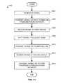
- FIG. 13is a flowchart depicting an exemplary method 1300 for communicating within a network, according to various embodiments.
- a multi-network interface device 200may become known to, and communicate with, other network devices within a communications network. These other network devices may be further instances of multi-network interface device 200 or other network devices known in the art.
- the multi-network interface device 200may act as a repeater in the network and/or otherwise forward messages to the other network devices via the method 1300 .
- the multi-network interface device 200interrogates the communications network by sending and receiving data packets.
- the powerline interface 204 , telephone line interface 202 , and/or the coaxial cable interface 206may be used to send and receive these data packets.
- the interrogationmay, in some embodiments, be initiated by network service provider such as a cable provider.
- the interrogationmay be configured to determine, for example, types of network devices connected to the communications network, MAC addresses associated with these network devices, which mediums and frequency bands may be used to communicate with each of these network devices, possible bandwidths, and/or the like.
- the interrogationmay include obtaining one or more quality of service (QoS) metric.
- QoS metricsmay be associated with specific media and/or specific frequency bands.
- multi-network interface device 200may be able to communication with another network device through more than one media and/or using more than one frequency band.
- the QoS metricmay be used to determine which media and/or which frequency bands are preferred for communicating with specific network devices.
- a messageis received by the multi-network interface device 200 from another network device or from the Ethernet interface 210 .
- the messagemay be received via an Ethernet cable, the powerline, the telephone line, or the coaxial cable.
- the messagemay comprise a request for communications, or a video data signal sent from a DVD player to a television.
- a pathway and associated medium for forwarding the message received in step 1304 to another network deviceis selected. This selection may be based on a QoS requirement, the type of network device to which the message is to be forwarded to, a communication interface associated with the network device, and/or a bandwidth requirement of the message to be sent. This selection may further use information gathered in step 1302 . For example, bandwidths and QoS metrics determined in step 1302 may be compared with bandwidth and QoS requirements.
- More than one mediumis optionally selected in step 1306 .
- datacan be sent via both telephone interface 202 and powerline interface 204 in parallel to achieve a required bandwidth.
- command and control signalsmay be sent via powerline interface 204 while high bandwidth video data can be sent via telephone interface 202 and/or a different frequency band of the powerline interface 204 .
- the multi-network interface device 200may select a pathway to a destination. This selection may be made, for example, to avoid passage through a junction box or other pathway associated with a low QoS metric. As such, the selected pathway may include transmitting the received message via the telephone line interface 202 or coaxial cable interface 206 , rather than the power line interface 204 .
- a step 1308specific frequency bands associated with the media selected in step 1306 are selected for transmitting the message. For example, if the selected media includes a power line coupled to power line interface 204 , then the low band 304 and/or the high band 306 may be selected in step 1308 . If the selected media includes a coaxial cable coupled to the coaxial cable interface 206 , then the frequency bands 320 and/or 324 may be selected. The selection of frequency bands is typically made based on criteria similar to the criteria used to select media in step 1306 . For example, the selection may be made based on comparisons of bandwidth and QoS requirements with metrics determined in step 1302 . More than one frequency band may be selected in step 1308 . In some embodiments, steps 1306 and 1308 are combined into a single step.
- the messageis transmitted via the selected media selected in step 1306 and the frequency bands selected in step 1308 .
- the transmissionmay include using an alternative medium (e.g., the telephone line) and/or shifting the message into another frequency band (e.g., from low band 304 to high band 306 ).
- FIG. 14is a flowchart depicting an exemplary method 1400 for bridging between mediums, according to various embodiments.
- bridging between mediumsmay be performed when there is a section of the network having a low QoS.
- two or more devicescommunicate the signal across multiple mediums. For example, in some communications networks using a powerline communications network, passing a signal through a junction box to traverse between sections of mains cable is difficult. Therefore, another medium may be used as a bridge between multiple sections of mains cable.
- a signalis generated.
- the signalis associated with one or more destinations.
- the signalis transmitted via a first powerline communications network to a first multi-network interface device 200 .
- the first multi-network interface device 200may be connected to a first section of mains cable.
- the signalis received at the first multi-network interface device 200 .
- the signalis shifted into another frequency band for transmission via the telephone line or coaxial cable.
- the signalis transmit from the first multi-network interface device 200 via the telephone line or coaxial cable to a second multi-network interface device 200 .
- the signalis received at the second multi-network interface device 200 via the telephone line or coaxial cable.
- the second devicemay be connected to, for example, a second section of mains cable separated from the first section of mains cable by a junction box.
- the signalis transmitted via the second powerline communications network.
- the signalmay be modified in frequency or content by the first or second multi-network interface device 200 .
- one of the communications interfaces included in multi-network interface device 200may be configured to communicate over a wireless network, such as a WiFi network, and comprise a wireless network antenna.
- the multi-network interface device 200may include a transformer configured to transform AC power received via the powerline to DC power (e.g., 5V, 12V, or 24V) to power a network apparatus.
- the multi-network interface device 200includes an AC/DC converter.
- Ethernet interface 210may be replaced by another computer interface such as a universal serial bus interface, a parallel port interface, a Peripheral Component Interconnect (PCI) interface, an Accelerated Graphics Port (AGP), a wireless interface, and/or other industry standard data interface.
- PCIPeripheral Component Interconnect
- AGPAccelerated Graphics Port
- Some embodiments of the multi-network interface device 200include external devices that comprise two interfaces configured to communicate via two types of mediums. These devices may or may not include a bypass as described herein, at least, in connection with FIG. 5 .
- One embodimentcomprises interfaces configured to communicate via the powerline on a low band and via a telephone line on a high band to one or more host interfaces configured to communicate using Ethernet 10/100/1000, WiFi, UWB, Wireless USB, USB2.0, Firewire, or the like.
- One embodimentcomprises interfaces configured to communicate via the powerline on a low band, via the powerline on a high band and via a telephone line on a high band to one or more host interfaces configured to communicate using Ethernet 10/100/1000, WiFi, UWB, Wireless USB, USB2.0, Firewire, or the like.
- One embodimentcomprises interfaces configured to communicate via the powerline on a low band and via a coaxial cable on a high band to one or more host interfaces configured to communicate using Ethernet 10/100/1000, WiFi, UWB, Wireless USB, USB2.0, Firewire, or the like.
- One embodimentcomprises interfaces configured to communicate via the powerline on a low band, via the powerline on a high band, and via a coaxial cable on a high band to one or more host interfaces configured to communicate using Ethernet 10/100/1000, WiFi, UWB, Wireless USB, USB2.0, Firewire, or the like.
- One embodimentcomprises interfaces configured to communicate via the powerline on a low band and via a coaxial cable on a high band using a mixer as described herein, at least, in connection with FIG. 8 to one or more host interfaces configured to communicate using Ethernet 10/100/1000, WiFi, UWB, Wireless USB, USB2.0, Firewire, or the like.
- One embodimentcomprises interfaces configured to communicate via the powerline on a low band, via the powerline on a high band, and via coaxial cable on a high band using a mixer as described herein, at least, in connection with FIG. 8 to one or more host interfaces configured to communicate using Ethernet 10/100/1000, WiFi, UWB, Wireless USB, USB2.0, Firewire, or the like.
- Some embodiments of the multi-network interface device 200include external devices that comprise three interfaces configured to communicate via three types of mediums. These devices may or may not include a bypass as described herein, at least, in connection with FIG. 5 .
- One embodimentcomprises interfaces configured to communicate via the powerline on a low band, via a telephone line on a high band, and via a coaxial cable on a high band to one or more host interfaces configured to communicate using Ethernet 10/100/1000, WiFi, UWB, Wireless USB, USB2.0, Firewire, or the like.
- One embodimentcomprises interfaces configured to communicate via the powerline on a low band, via the powerline on a high band, via a telephone line on a high band, and via a coaxial cable on a high band to one or more host interfaces configured to communicate using Ethernet 10/100/1000, WiFi, UWB, Wireless USB, USB2.0, Firewire, or the like.
- One embodimentcomprises interfaces configured to communicate via the powerline-on a low band, via the powerline on a high band, via a telephone line on a high band, and via a coaxial cable on a high band using a mixer as described herein, at least, in connection with FIG. 8 to one or more host interfaces configured to communicate using Ethernet 10/100/1000, WiFi, UWB, Wireless USB, USB2.0, Firewire, or the like.
- Some embodiments of the multi-network interface device 200include embedded devices that comprise two interfaces configured to communicate via two types of mediums. These devices may or may not communicate over mediums that also have signals for other services in other frequency bands. Examples of these services include DOCSIS, Cable TV, or the like in a coaxial cable modem and/or DSL, Voice, or the like in a DSL Home Gateway device.
- One embodimentcomprises interfaces configured to communicate via the powerline on a low band and via a telephone line on a high band to one or more host interfaces such as MII, GMII, PCI, MiniPCI, PCI-X, PCIe, Host Processor Interface, SPI, UART, or the like.
- One embodimentcomprises interfaces configured to communicate via the powerline on a low band, via the powerline on a high band, and via a telephone line on a high band to one or more host interfaces such as MII, GMII, PCI, MiniPCI, PCI-X, PCIe, Host Processor Interface, SPI, UART, or the like.
- One embodimentcomprises interfaces configured to communicate via the powerline on a low band and via a coaxial cable on a high band to one or more host interfaces such as MII, GMII, PCI, MiniPCI, PCI-X, PCIe, Host Processor Interface, SPI, UART, or the like.
- One embodimentcomprises interfaces configured to communicate via the powerline on a low band, via the powerline on a high band, and via a coaxial cable on a high band to one or more host interfaces such as MII, GMII, PCI, MiniPCI, PCI-X, PCIe, Host Processor Interface, SPI, UART, or the like.
- One embodimentcomprises interfaces configured to communicate via the powerline on a low band and via a coaxial cable on a high band using a mixer as described herein, at least, in connection with FIG. 8 to one or more host interfaces such as MII, GMII, PCI, MiniPCI, PCI-X, PCIe, Host Processor Interface, SPI, UART, or the like.
- One embodimentcomprises interfaces configured to communicate via the powerline on a low band, via the powerline on a high band, and via a coaxial cable on a high band using a mixer as described herein, at least, in connection with FIG. 8 to one or more host interfaces such as MII, GMII, PCI, MiniPCI, PCI-X, PCIe, Host Processor Interface, SPI, UART, or the like.
- Some embodiments of the multi-network interface device 200include embedded devices that comprise three interfaces configured to communicate via three types of mediums. These devices may or may not communicate over mediums that also have signals for other services in other frequency bands. Examples of these services include DOCSIS, Cable TV, or the like in a coaxial cable modem and/or DSL, Voice, or the like in a DSL Home Gateway device.
- One embodimentcomprises interfaces configured to communicate via the powerline on a low band, via a telephone line on a high band, and via a coaxial cable on a high band to one or more host interfaces to one or more host interfaces such as MII, GMII, PCI, MiniPCI, PCI-X, PCIe, Host Processor Interface, SPI, UART, or the like.
- host interfacessuch as MII, GMII, PCI, MiniPCI, PCI-X, PCIe, Host Processor Interface, SPI, UART, or the like.
- One embodimentcomprises interfaces configured to communicate via the powerline on a low band, via the powerline on a high band; via a telephone line on a high band, and via a coaxial cable on a high band to one or more host interfaces to one or more host interfaces such as MII, GMII, PCI, MiniPCI, PCI-X, PCIe, Host Processor Interface, SPI, UART, or the like.
- host interfacessuch as MII, GMII, PCI, MiniPCI, PCI-X, PCIe, Host Processor Interface, SPI, UART, or the like.
- One embodimentcomprises interfaces configured to communicate via the powerline on a low band, via a telephone line on a high band, and via a coaxial cable on a high band using a mixer as described herein, at least, in connection with FIG. 8 to one or more host interfaces to one or more host interfaces such as MII, GMII, PCI, MiniPCI, PCI-X, PCIe, Host Processor Interface, SPI, UART, or the like.
- One embodimentcomprises interfaces configured to communicate via the powerline on a low band, via the powerline on a high band, via a telephone line on a high band, and via a coaxial cable on a high band using a mixer as described herein, at least, in connection with FIG. 8 to one or more host interfaces to one or more host interfaces such as MII, GMII, PCI, MiniPCI, PCI-X, PCIe, Host Processor Interface, SPI, UART, or the like.
- Some embodiments of the multi-network interface device 200include external repeater devices that comprise two or three interfaces configured to communicate via two or three types of mediums. These devices may or may not include a bypass as described herein, at least, in connection with FIG. 5 .
- One embodimentis configured to repeat signals between the powerline on a low band and the telephone line on a high band.
- One embodimentis configured to repeat signals between the powerline on a low band, the power line on a high band, and the telephone line on a high band.
- One embodimentis configured to repeat signals between the powerline on a low band and the coaxial-cable on a high band.
- One embodimentis configured to repeat signals between the powerline on a low band, the power line on a high band, and the coaxial cable on a high band.
- One embodimentis configured to repeat signals between the powerline on a low band and the coaxial cable on a high band using a mixer as described herein, at least, in connection with FIG. 8 .
- One embodimentis configured to repeat signals between the powerline on a low band, the power line on a high band, and the coaxial cable on a high band using a mixer as described herein, at least, in connection with FIG. 8 .
- One embodimentis configured to repeat signals between the powerline on a low band, the telephone line on a high band, and the coaxial cable on the high band.
- One embodimentis configured to repeat signals between the powerline on a low band, the power line on a high band, the telephone line on a high band, and the coaxial cable on the high band.
- One embodimentis configured to repeat signals between the powerline on a low band, the telephone line on a high band, and the coaxial cable on a high band using a mixer as described herein, at least, in connection with FIG. 8 .
- One embodimentis configured to repeat signals between the powerline on a low band, the power line on a high band, the telephone line on a high band, and the coaxial cable on a high band using a mixer as described herein, at least, in connection with FIG. 8 .
- Some embodiments of the multi-network interface device 200comprise two or three network interfaces and a host interface comprising an I2S or Sony/Philips Digital Interconnect Format (SPDIF) compliant interface for transfer of an audio stream.
- a host interfacecomprising an I2S or Sony/Philips Digital Interconnect Format (SPDIF) compliant interface for transfer of an audio stream.
- SPDIFSony/Philips Digital Interconnect Format
- One embodimentcomprises interfaces configured to communicate via the powerline on a low band and the telephone line on a high band to the host interface.
- One embodimentcomprises interfaces configured to communicate via the powerline on a low band, via the powerline on a high band, and the telephone line on a high band to the host interface.
- One embodimentcomprises interfaces configured to communicate via the powerline on a low band and the coaxial cable on a high band to the host interface.
- One embodimentcomprises interfaces configured to communicate via the powerline on a low band, via the powerline on a high band, and the coaxial cable on a high band to the host interface.
- One embodimentcomprises interfaces configured to communicate via the powerline on a low band, and via the coaxial cable on a high band using a mixer as described herein, at least, in connection with FIG. 8 to the host interface.
- One embodimentcomprises interfaces configured to communicate via the powerline on a low band, via the powerline on a high band, and via the coaxial cable on a high band using a mixer as described herein, at least, in connection with FIG. 8 to the host interface.
- One embodimentcomprises interfaces configured to communicate via the powerline on a low band, the telephone line on a high band to the host interface, and the coaxial cable on the high band.
- One embodimentcomprises interfaces configured to communicate via the powerline on a low band, via the powerline on a high band, via the telephone line on a high band to the host interface, and via the coaxial cable on a high band.
- One embodimentcomprises interfaces configured to communicate via the powerline on a low band, via the telephone line on the high band, and via the coaxial cable on a high band using a mixer as described herein, at least, in connection with FIG. 8 to the host interface.
- One embodimentcomprises interfaces configured to communicate via the powerline on a low band, via the powerline on a high band, via the telephone line on the high band, and via the coaxial cable on a high band using a mixer as described herein, at least, in connection with FIG. 8 to the host interface.
Landscapes
- Engineering & Computer Science (AREA)
- Computer Networks & Wireless Communication (AREA)
- Signal Processing (AREA)
- Power Engineering (AREA)
- Cable Transmission Systems, Equalization Of Radio And Reduction Of Echo (AREA)
- Small-Scale Networks (AREA)
- Telephonic Communication Services (AREA)
Abstract
Description
Claims (21)
Priority Applications (7)
| Application Number | Priority Date | Filing Date | Title |
|---|---|---|---|
| US11/752,887US8406239B2 (en) | 2005-10-03 | 2007-05-23 | Multi-wideband communications over multiple mediums |
| EP08750759.6AEP2149199B1 (en) | 2007-05-23 | 2008-05-21 | Multi-wideband communications over multiple mediums |
| PCT/GB2008/050364WO2008142449A1 (en) | 2007-05-23 | 2008-05-21 | Multi-wideband communications over multiple mediums |
| KR1020097026548AKR101484288B1 (en) | 2007-05-23 | 2008-05-21 | Multi-wideband communications over multiple mediums |
| JP2010508906AJP2010528513A (en) | 2007-05-23 | 2008-05-21 | Multi-wideband communication over multiple media |
| US12/972,302US20110205918A1 (en) | 2005-10-03 | 2010-12-17 | Apparatus for Power Line and Wireless Communications |
| US13/781,105US9036649B2 (en) | 2005-10-03 | 2013-02-28 | Multi-wideband communications over multiple mediums |
Applications Claiming Priority (7)
| Application Number | Priority Date | Filing Date | Title |
|---|---|---|---|
| EP05256179.2 | 2005-10-03 | ||
| EP05256179.2AEP1770870B1 (en) | 2005-10-03 | 2005-10-03 | Powerline communication device and method |
| EP05256179 | 2005-10-03 | ||
| US11/536,539US20070076666A1 (en) | 2005-10-03 | 2006-09-28 | Multi-Wideband Communications over Power Lines |
| US11/562,380US7808985B2 (en) | 2006-11-21 | 2006-11-21 | Network repeater |
| US11/619,167US20080159358A1 (en) | 2007-01-02 | 2007-01-02 | Unknown Destination Traffic Repetition |
| US11/752,887US8406239B2 (en) | 2005-10-03 | 2007-05-23 | Multi-wideband communications over multiple mediums |
Related Parent Applications (2)
| Application Number | Title | Priority Date | Filing Date |
|---|---|---|---|
| US11/536,539Continuation-In-PartUS20070076666A1 (en) | 2005-10-03 | 2006-09-28 | Multi-Wideband Communications over Power Lines |
| US11/562,380Continuation-In-PartUS7808985B2 (en) | 2005-10-03 | 2006-11-21 | Network repeater |
Related Child Applications (2)
| Application Number | Title | Priority Date | Filing Date |
|---|---|---|---|
| US12/972,302Continuation-In-PartUS20110205918A1 (en) | 2005-10-03 | 2010-12-17 | Apparatus for Power Line and Wireless Communications |
| US13/781,105ContinuationUS9036649B2 (en) | 2005-10-03 | 2013-02-28 | Multi-wideband communications over multiple mediums |
Publications (2)
| Publication Number | Publication Date |
|---|---|
| US20080130640A1 US20080130640A1 (en) | 2008-06-05 |
| US8406239B2true US8406239B2 (en) | 2013-03-26 |
Family
ID=39672002
Family Applications (2)
| Application Number | Title | Priority Date | Filing Date |
|---|---|---|---|
| US11/752,887Expired - Fee RelatedUS8406239B2 (en) | 2005-10-03 | 2007-05-23 | Multi-wideband communications over multiple mediums |
| US13/781,105Active2027-03-25US9036649B2 (en) | 2005-10-03 | 2013-02-28 | Multi-wideband communications over multiple mediums |
Family Applications After (1)
| Application Number | Title | Priority Date | Filing Date |
|---|---|---|---|
| US13/781,105Active2027-03-25US9036649B2 (en) | 2005-10-03 | 2013-02-28 | Multi-wideband communications over multiple mediums |
Country Status (5)
| Country | Link |
|---|---|
| US (2) | US8406239B2 (en) |
| EP (1) | EP2149199B1 (en) |
| JP (1) | JP2010528513A (en) |
| KR (1) | KR101484288B1 (en) |
| WO (1) | WO2008142449A1 (en) |
Cited By (170)
| Publication number | Priority date | Publication date | Assignee | Title |
|---|---|---|---|---|
| US20140103706A1 (en)* | 2012-10-15 | 2014-04-17 | Broadcom Corporation | Power line communication (plc) coupling through an external power supply |
| US8897697B1 (en) | 2013-11-06 | 2014-11-25 | At&T Intellectual Property I, Lp | Millimeter-wave surface-wave communications |
| US9113347B2 (en) | 2012-12-05 | 2015-08-18 | At&T Intellectual Property I, Lp | Backhaul link for distributed antenna system |
| US9209902B2 (en) | 2013-12-10 | 2015-12-08 | At&T Intellectual Property I, L.P. | Quasi-optical coupler |
| US9312895B1 (en) | 2008-08-07 | 2016-04-12 | Hypres, Inc. | Two stage radio frequency interference cancellation system and method |
| US9312919B1 (en) | 2014-10-21 | 2016-04-12 | At&T Intellectual Property I, Lp | Transmission device with impairment compensation and methods for use therewith |
| US20160164573A1 (en)* | 2014-12-04 | 2016-06-09 | At&T Intellectual Property I, Lp | Method and apparatus for configuring a communication interface |
| US9461706B1 (en) | 2015-07-31 | 2016-10-04 | At&T Intellectual Property I, Lp | Method and apparatus for exchanging communication signals |
| US9490869B1 (en) | 2015-05-14 | 2016-11-08 | At&T Intellectual Property I, L.P. | Transmission medium having multiple cores and methods for use therewith |
| US9503189B2 (en) | 2014-10-10 | 2016-11-22 | At&T Intellectual Property I, L.P. | Method and apparatus for arranging communication sessions in a communication system |
| US9509415B1 (en) | 2015-06-25 | 2016-11-29 | At&T Intellectual Property I, L.P. | Methods and apparatus for inducing a fundamental wave mode on a transmission medium |
| US9520945B2 (en) | 2014-10-21 | 2016-12-13 | At&T Intellectual Property I, L.P. | Apparatus for providing communication services and methods thereof |
| US9525524B2 (en) | 2013-05-31 | 2016-12-20 | At&T Intellectual Property I, L.P. | Remote distributed antenna system |
| US9525210B2 (en) | 2014-10-21 | 2016-12-20 | At&T Intellectual Property I, L.P. | Guided-wave transmission device with non-fundamental mode propagation and methods for use therewith |
| US9531427B2 (en) | 2014-11-20 | 2016-12-27 | At&T Intellectual Property I, L.P. | Transmission device with mode division multiplexing and methods for use therewith |
| US9564947B2 (en) | 2014-10-21 | 2017-02-07 | At&T Intellectual Property I, L.P. | Guided-wave transmission device with diversity and methods for use therewith |
| US9577306B2 (en) | 2014-10-21 | 2017-02-21 | At&T Intellectual Property I, L.P. | Guided-wave transmission device and methods for use therewith |
| US20170055031A1 (en)* | 2015-08-19 | 2017-02-23 | Opentv, Inc. | Method to transmit and receive mpeg-ts over a thunderbolt cable |
| US9608692B2 (en) | 2015-06-11 | 2017-03-28 | At&T Intellectual Property I, L.P. | Repeater and methods for use therewith |
| US9608740B2 (en) | 2015-07-15 | 2017-03-28 | At&T Intellectual Property I, L.P. | Method and apparatus for launching a wave mode that mitigates interference |
| US9615269B2 (en) | 2014-10-02 | 2017-04-04 | At&T Intellectual Property I, L.P. | Method and apparatus that provides fault tolerance in a communication network |
| US9628854B2 (en) | 2014-09-29 | 2017-04-18 | At&T Intellectual Property I, L.P. | Method and apparatus for distributing content in a communication network |
| US9628116B2 (en) | 2015-07-14 | 2017-04-18 | At&T Intellectual Property I, L.P. | Apparatus and methods for transmitting wireless signals |
| US9640850B2 (en) | 2015-06-25 | 2017-05-02 | At&T Intellectual Property I, L.P. | Methods and apparatus for inducing a non-fundamental wave mode on a transmission medium |
| US9653770B2 (en) | 2014-10-21 | 2017-05-16 | At&T Intellectual Property I, L.P. | Guided wave coupler, coupling module and methods for use therewith |
| US9654173B2 (en) | 2014-11-20 | 2017-05-16 | At&T Intellectual Property I, L.P. | Apparatus for powering a communication device and methods thereof |
| US9667317B2 (en) | 2015-06-15 | 2017-05-30 | At&T Intellectual Property I, L.P. | Method and apparatus for providing security using network traffic adjustments |
| US9680670B2 (en) | 2014-11-20 | 2017-06-13 | At&T Intellectual Property I, L.P. | Transmission device with channel equalization and control and methods for use therewith |
| US9685992B2 (en) | 2014-10-03 | 2017-06-20 | At&T Intellectual Property I, L.P. | Circuit panel network and methods thereof |
| US9692101B2 (en) | 2014-08-26 | 2017-06-27 | At&T Intellectual Property I, L.P. | Guided wave couplers for coupling electromagnetic waves between a waveguide surface and a surface of a wire |
| US9705561B2 (en) | 2015-04-24 | 2017-07-11 | At&T Intellectual Property I, L.P. | Directional coupling device and methods for use therewith |
| US9705571B2 (en) | 2015-09-16 | 2017-07-11 | At&T Intellectual Property I, L.P. | Method and apparatus for use with a radio distributed antenna system |
| US9722318B2 (en) | 2015-07-14 | 2017-08-01 | At&T Intellectual Property I, L.P. | Method and apparatus for coupling an antenna to a device |
| US9729197B2 (en) | 2015-10-01 | 2017-08-08 | At&T Intellectual Property I, L.P. | Method and apparatus for communicating network management traffic over a network |
| US9735833B2 (en) | 2015-07-31 | 2017-08-15 | At&T Intellectual Property I, L.P. | Method and apparatus for communications management in a neighborhood network |
| US9742462B2 (en) | 2014-12-04 | 2017-08-22 | At&T Intellectual Property I, L.P. | Transmission medium and communication interfaces and methods for use therewith |
| US9749053B2 (en) | 2015-07-23 | 2017-08-29 | At&T Intellectual Property I, L.P. | Node device, repeater and methods for use therewith |
| US9748626B2 (en) | 2015-05-14 | 2017-08-29 | At&T Intellectual Property I, L.P. | Plurality of cables having different cross-sectional shapes which are bundled together to form a transmission medium |
| US9749013B2 (en) | 2015-03-17 | 2017-08-29 | At&T Intellectual Property I, L.P. | Method and apparatus for reducing attenuation of electromagnetic waves guided by a transmission medium |
| US9756549B2 (en) | 2014-03-14 | 2017-09-05 | goTenna Inc. | System and method for digital communication between computing devices |
| US9755697B2 (en) | 2014-09-15 | 2017-09-05 | At&T Intellectual Property I, L.P. | Method and apparatus for sensing a condition in a transmission medium of electromagnetic waves |
| US9762289B2 (en) | 2014-10-14 | 2017-09-12 | At&T Intellectual Property I, L.P. | Method and apparatus for transmitting or receiving signals in a transportation system |
| US9769128B2 (en) | 2015-09-28 | 2017-09-19 | At&T Intellectual Property I, L.P. | Method and apparatus for encryption of communications over a network |
| US9769020B2 (en) | 2014-10-21 | 2017-09-19 | At&T Intellectual Property I, L.P. | Method and apparatus for responding to events affecting communications in a communication network |
| US9780834B2 (en) | 2014-10-21 | 2017-10-03 | At&T Intellectual Property I, L.P. | Method and apparatus for transmitting electromagnetic waves |
| US9793955B2 (en) | 2015-04-24 | 2017-10-17 | At&T Intellectual Property I, Lp | Passive electrical coupling device and methods for use therewith |
| US9793951B2 (en) | 2015-07-15 | 2017-10-17 | At&T Intellectual Property I, L.P. | Method and apparatus for launching a wave mode that mitigates interference |
| US9793954B2 (en) | 2015-04-28 | 2017-10-17 | At&T Intellectual Property I, L.P. | Magnetic coupling device and methods for use therewith |
| US9800327B2 (en) | 2014-11-20 | 2017-10-24 | At&T Intellectual Property I, L.P. | Apparatus for controlling operations of a communication device and methods thereof |
| US9820146B2 (en) | 2015-06-12 | 2017-11-14 | At&T Intellectual Property I, L.P. | Method and apparatus for authentication and identity management of communicating devices |
| US9838896B1 (en) | 2016-12-09 | 2017-12-05 | At&T Intellectual Property I, L.P. | Method and apparatus for assessing network coverage |
| US9836957B2 (en) | 2015-07-14 | 2017-12-05 | At&T Intellectual Property I, L.P. | Method and apparatus for communicating with premises equipment |
| US9847566B2 (en) | 2015-07-14 | 2017-12-19 | At&T Intellectual Property I, L.P. | Method and apparatus for adjusting a field of a signal to mitigate interference |
| US9847850B2 (en) | 2014-10-14 | 2017-12-19 | At&T Intellectual Property I, L.P. | Method and apparatus for adjusting a mode of communication in a communication network |
| US9853342B2 (en) | 2015-07-14 | 2017-12-26 | At&T Intellectual Property I, L.P. | Dielectric transmission medium connector and methods for use therewith |
| US9860075B1 (en) | 2016-08-26 | 2018-01-02 | At&T Intellectual Property I, L.P. | Method and communication node for broadband distribution |
| US9865911B2 (en) | 2015-06-25 | 2018-01-09 | At&T Intellectual Property I, L.P. | Waveguide system for slot radiating first electromagnetic waves that are combined into a non-fundamental wave mode second electromagnetic wave on a transmission medium |
| US9866309B2 (en) | 2015-06-03 | 2018-01-09 | At&T Intellectual Property I, Lp | Host node device and methods for use therewith |
| US9871282B2 (en) | 2015-05-14 | 2018-01-16 | At&T Intellectual Property I, L.P. | At least one transmission medium having a dielectric surface that is covered at least in part by a second dielectric |
| US9871283B2 (en) | 2015-07-23 | 2018-01-16 | At&T Intellectual Property I, Lp | Transmission medium having a dielectric core comprised of plural members connected by a ball and socket configuration |
| US9876264B2 (en) | 2015-10-02 | 2018-01-23 | At&T Intellectual Property I, Lp | Communication system, guided wave switch and methods for use therewith |
| US9876605B1 (en) | 2016-10-21 | 2018-01-23 | At&T Intellectual Property I, L.P. | Launcher and coupling system to support desired guided wave mode |
| US9876571B2 (en) | 2015-02-20 | 2018-01-23 | At&T Intellectual Property I, Lp | Guided-wave transmission device with non-fundamental mode propagation and methods for use therewith |
| US9882277B2 (en) | 2015-10-02 | 2018-01-30 | At&T Intellectual Property I, Lp | Communication device and antenna assembly with actuated gimbal mount |
| US9882257B2 (en) | 2015-07-14 | 2018-01-30 | At&T Intellectual Property I, L.P. | Method and apparatus for launching a wave mode that mitigates interference |
| US9893795B1 (en) | 2016-12-07 | 2018-02-13 | At&T Intellectual Property I, Lp | Method and repeater for broadband distribution |
| US9906269B2 (en) | 2014-09-17 | 2018-02-27 | At&T Intellectual Property I, L.P. | Monitoring and mitigating conditions in a communication network |
| US9904535B2 (en) | 2015-09-14 | 2018-02-27 | At&T Intellectual Property I, L.P. | Method and apparatus for distributing software |
| US9912419B1 (en) | 2016-08-24 | 2018-03-06 | At&T Intellectual Property I, L.P. | Method and apparatus for managing a fault in a distributed antenna system |
| US9912381B2 (en) | 2015-06-03 | 2018-03-06 | At&T Intellectual Property I, Lp | Network termination and methods for use therewith |
| US9912587B2 (en) | 2011-07-25 | 2018-03-06 | Sony Corporation | Communication apparatus, communication method, and communication system |
| US9911020B1 (en) | 2016-12-08 | 2018-03-06 | At&T Intellectual Property I, L.P. | Method and apparatus for tracking via a radio frequency identification device |
| US9912027B2 (en) | 2015-07-23 | 2018-03-06 | At&T Intellectual Property I, L.P. | Method and apparatus for exchanging communication signals |
| US9913139B2 (en) | 2015-06-09 | 2018-03-06 | At&T Intellectual Property I, L.P. | Signal fingerprinting for authentication of communicating devices |
| US9917341B2 (en) | 2015-05-27 | 2018-03-13 | At&T Intellectual Property I, L.P. | Apparatus and method for launching electromagnetic waves and for modifying radial dimensions of the propagating electromagnetic waves |
| US9927517B1 (en) | 2016-12-06 | 2018-03-27 | At&T Intellectual Property I, L.P. | Apparatus and methods for sensing rainfall |
| US9948333B2 (en) | 2015-07-23 | 2018-04-17 | At&T Intellectual Property I, L.P. | Method and apparatus for wireless communications to mitigate interference |
| US9948354B2 (en) | 2015-04-28 | 2018-04-17 | At&T Intellectual Property I, L.P. | Magnetic coupling device with reflective plate and methods for use therewith |
| US9954287B2 (en) | 2014-11-20 | 2018-04-24 | At&T Intellectual Property I, L.P. | Apparatus for converting wireless signals and electromagnetic waves and methods thereof |
| US9967173B2 (en) | 2015-07-31 | 2018-05-08 | At&T Intellectual Property I, L.P. | Method and apparatus for authentication and identity management of communicating devices |
| US9973940B1 (en) | 2017-02-27 | 2018-05-15 | At&T Intellectual Property I, L.P. | Apparatus and methods for dynamic impedance matching of a guided wave launcher |
| US9991580B2 (en) | 2016-10-21 | 2018-06-05 | At&T Intellectual Property I, L.P. | Launcher and coupling system for guided wave mode cancellation |
| US9999038B2 (en) | 2013-05-31 | 2018-06-12 | At&T Intellectual Property I, L.P. | Remote distributed antenna system |
| US9998870B1 (en) | 2016-12-08 | 2018-06-12 | At&T Intellectual Property I, L.P. | Method and apparatus for proximity sensing |
| US9997819B2 (en) | 2015-06-09 | 2018-06-12 | At&T Intellectual Property I, L.P. | Transmission medium and method for facilitating propagation of electromagnetic waves via a core |
| US10009063B2 (en) | 2015-09-16 | 2018-06-26 | At&T Intellectual Property I, L.P. | Method and apparatus for use with a radio distributed antenna system having an out-of-band reference signal |
| US10009065B2 (en) | 2012-12-05 | 2018-06-26 | At&T Intellectual Property I, L.P. | Backhaul link for distributed antenna system |
| US10009901B2 (en) | 2015-09-16 | 2018-06-26 | At&T Intellectual Property I, L.P. | Method, apparatus, and computer-readable storage medium for managing utilization of wireless resources between base stations |
| US10020844B2 (en) | 2016-12-06 | 2018-07-10 | T&T Intellectual Property I, L.P. | Method and apparatus for broadcast communication via guided waves |
| US10020587B2 (en) | 2015-07-31 | 2018-07-10 | At&T Intellectual Property I, L.P. | Radial antenna and methods for use therewith |
| US10027397B2 (en) | 2016-12-07 | 2018-07-17 | At&T Intellectual Property I, L.P. | Distributed antenna system and methods for use therewith |
| US10033107B2 (en) | 2015-07-14 | 2018-07-24 | At&T Intellectual Property I, L.P. | Method and apparatus for coupling an antenna to a device |
| US10033108B2 (en) | 2015-07-14 | 2018-07-24 | At&T Intellectual Property I, L.P. | Apparatus and methods for generating an electromagnetic wave having a wave mode that mitigates interference |
| US10044409B2 (en) | 2015-07-14 | 2018-08-07 | At&T Intellectual Property I, L.P. | Transmission medium and methods for use therewith |
| US10051629B2 (en) | 2015-09-16 | 2018-08-14 | At&T Intellectual Property I, L.P. | Method and apparatus for use with a radio distributed antenna system having an in-band reference signal |
| US10051483B2 (en) | 2015-10-16 | 2018-08-14 | At&T Intellectual Property I, L.P. | Method and apparatus for directing wireless signals |
| US10069535B2 (en) | 2016-12-08 | 2018-09-04 | At&T Intellectual Property I, L.P. | Apparatus and methods for launching electromagnetic waves having a certain electric field structure |
| US10074890B2 (en) | 2015-10-02 | 2018-09-11 | At&T Intellectual Property I, L.P. | Communication device and antenna with integrated light assembly |
| US10079661B2 (en) | 2015-09-16 | 2018-09-18 | At&T Intellectual Property I, L.P. | Method and apparatus for use with a radio distributed antenna system having a clock reference |
| US10090606B2 (en) | 2015-07-15 | 2018-10-02 | At&T Intellectual Property I, L.P. | Antenna system with dielectric array and methods for use therewith |
| US10090594B2 (en) | 2016-11-23 | 2018-10-02 | At&T Intellectual Property I, L.P. | Antenna system having structural configurations for assembly |
| US10103422B2 (en) | 2016-12-08 | 2018-10-16 | At&T Intellectual Property I, L.P. | Method and apparatus for mounting network devices |
| US10103801B2 (en) | 2015-06-03 | 2018-10-16 | At&T Intellectual Property I, L.P. | Host node device and methods for use therewith |
| US10135147B2 (en) | 2016-10-18 | 2018-11-20 | At&T Intellectual Property I, L.P. | Apparatus and methods for launching guided waves via an antenna |
| US10135146B2 (en) | 2016-10-18 | 2018-11-20 | At&T Intellectual Property I, L.P. | Apparatus and methods for launching guided waves via circuits |
| US10136434B2 (en) | 2015-09-16 | 2018-11-20 | At&T Intellectual Property I, L.P. | Method and apparatus for use with a radio distributed antenna system having an ultra-wideband control channel |
| US10135145B2 (en) | 2016-12-06 | 2018-11-20 | At&T Intellectual Property I, L.P. | Apparatus and methods for generating an electromagnetic wave along a transmission medium |
| US10142086B2 (en) | 2015-06-11 | 2018-11-27 | At&T Intellectual Property I, L.P. | Repeater and methods for use therewith |
| US10139820B2 (en) | 2016-12-07 | 2018-11-27 | At&T Intellectual Property I, L.P. | Method and apparatus for deploying equipment of a communication system |
| US10144036B2 (en) | 2015-01-30 | 2018-12-04 | At&T Intellectual Property I, L.P. | Method and apparatus for mitigating interference affecting a propagation of electromagnetic waves guided by a transmission medium |
| US10148016B2 (en) | 2015-07-14 | 2018-12-04 | At&T Intellectual Property I, L.P. | Apparatus and methods for communicating utilizing an antenna array |
| US10154493B2 (en) | 2015-06-03 | 2018-12-11 | At&T Intellectual Property I, L.P. | Network termination and methods for use therewith |
| US10170840B2 (en) | 2015-07-14 | 2019-01-01 | At&T Intellectual Property I, L.P. | Apparatus and methods for sending or receiving electromagnetic signals |
| US10168695B2 (en) | 2016-12-07 | 2019-01-01 | At&T Intellectual Property I, L.P. | Method and apparatus for controlling an unmanned aircraft |
| US10178445B2 (en) | 2016-11-23 | 2019-01-08 | At&T Intellectual Property I, L.P. | Methods, devices, and systems for load balancing between a plurality of waveguides |
| US10205655B2 (en) | 2015-07-14 | 2019-02-12 | At&T Intellectual Property I, L.P. | Apparatus and methods for communicating utilizing an antenna array and multiple communication paths |
| US10225025B2 (en) | 2016-11-03 | 2019-03-05 | At&T Intellectual Property I, L.P. | Method and apparatus for detecting a fault in a communication system |
| US10224634B2 (en) | 2016-11-03 | 2019-03-05 | At&T Intellectual Property I, L.P. | Methods and apparatus for adjusting an operational characteristic of an antenna |
| US10243270B2 (en) | 2016-12-07 | 2019-03-26 | At&T Intellectual Property I, L.P. | Beam adaptive multi-feed dielectric antenna system and methods for use therewith |
| US10243784B2 (en) | 2014-11-20 | 2019-03-26 | At&T Intellectual Property I, L.P. | System for generating topology information and methods thereof |
| US10264586B2 (en) | 2016-12-09 | 2019-04-16 | At&T Mobility Ii Llc | Cloud-based packet controller and methods for use therewith |
| US10291334B2 (en) | 2016-11-03 | 2019-05-14 | At&T Intellectual Property I, L.P. | System for detecting a fault in a communication system |
| US10291311B2 (en) | 2016-09-09 | 2019-05-14 | At&T Intellectual Property I, L.P. | Method and apparatus for mitigating a fault in a distributed antenna system |
| US10298293B2 (en) | 2017-03-13 | 2019-05-21 | At&T Intellectual Property I, L.P. | Apparatus of communication utilizing wireless network devices |
| US10305190B2 (en) | 2016-12-01 | 2019-05-28 | At&T Intellectual Property I, L.P. | Reflecting dielectric antenna system and methods for use therewith |
| US10312567B2 (en) | 2016-10-26 | 2019-06-04 | At&T Intellectual Property I, L.P. | Launcher with planar strip antenna and methods for use therewith |
| US10320586B2 (en) | 2015-07-14 | 2019-06-11 | At&T Intellectual Property I, L.P. | Apparatus and methods for generating non-interfering electromagnetic waves on an insulated transmission medium |
| US10326689B2 (en) | 2016-12-08 | 2019-06-18 | At&T Intellectual Property I, L.P. | Method and system for providing alternative communication paths |
| US10326494B2 (en) | 2016-12-06 | 2019-06-18 | At&T Intellectual Property I, L.P. | Apparatus for measurement de-embedding and methods for use therewith |
| US10340601B2 (en) | 2016-11-23 | 2019-07-02 | At&T Intellectual Property I, L.P. | Multi-antenna system and methods for use therewith |
| US10340983B2 (en) | 2016-12-09 | 2019-07-02 | At&T Intellectual Property I, L.P. | Method and apparatus for surveying remote sites via guided wave communications |
| US10340573B2 (en) | 2016-10-26 | 2019-07-02 | At&T Intellectual Property I, L.P. | Launcher with cylindrical coupling device and methods for use therewith |
| US10340603B2 (en) | 2016-11-23 | 2019-07-02 | At&T Intellectual Property I, L.P. | Antenna system having shielded structural configurations for assembly |
| US10341142B2 (en) | 2015-07-14 | 2019-07-02 | At&T Intellectual Property I, L.P. | Apparatus and methods for generating non-interfering electromagnetic waves on an uninsulated conductor |
| US10340600B2 (en) | 2016-10-18 | 2019-07-02 | At&T Intellectual Property I, L.P. | Apparatus and methods for launching guided waves via plural waveguide systems |
| US10348391B2 (en) | 2015-06-03 | 2019-07-09 | At&T Intellectual Property I, L.P. | Client node device with frequency conversion and methods for use therewith |
| US10355367B2 (en) | 2015-10-16 | 2019-07-16 | At&T Intellectual Property I, L.P. | Antenna structure for exchanging wireless signals |
| US10361489B2 (en) | 2016-12-01 | 2019-07-23 | At&T Intellectual Property I, L.P. | Dielectric dish antenna system and methods for use therewith |
| US10359749B2 (en) | 2016-12-07 | 2019-07-23 | At&T Intellectual Property I, L.P. | Method and apparatus for utilities management via guided wave communication |
| US10374316B2 (en) | 2016-10-21 | 2019-08-06 | At&T Intellectual Property I, L.P. | System and dielectric antenna with non-uniform dielectric |
| US10382976B2 (en) | 2016-12-06 | 2019-08-13 | At&T Intellectual Property I, L.P. | Method and apparatus for managing wireless communications based on communication paths and network device positions |
| US10389029B2 (en) | 2016-12-07 | 2019-08-20 | At&T Intellectual Property I, L.P. | Multi-feed dielectric antenna system with core selection and methods for use therewith |
| US10389037B2 (en) | 2016-12-08 | 2019-08-20 | At&T Intellectual Property I, L.P. | Apparatus and methods for selecting sections of an antenna array and use therewith |
| US10396887B2 (en) | 2015-06-03 | 2019-08-27 | At&T Intellectual Property I, L.P. | Client node device and methods for use therewith |
| US10411356B2 (en) | 2016-12-08 | 2019-09-10 | At&T Intellectual Property I, L.P. | Apparatus and methods for selectively targeting communication devices with an antenna array |
| US10439675B2 (en) | 2016-12-06 | 2019-10-08 | At&T Intellectual Property I, L.P. | Method and apparatus for repeating guided wave communication signals |
| US10446936B2 (en) | 2016-12-07 | 2019-10-15 | At&T Intellectual Property I, L.P. | Multi-feed dielectric antenna system and methods for use therewith |
| US10498044B2 (en) | 2016-11-03 | 2019-12-03 | At&T Intellectual Property I, L.P. | Apparatus for configuring a surface of an antenna |
| US10530505B2 (en) | 2016-12-08 | 2020-01-07 | At&T Intellectual Property I, L.P. | Apparatus and methods for launching electromagnetic waves along a transmission medium |
| US10535928B2 (en) | 2016-11-23 | 2020-01-14 | At&T Intellectual Property I, L.P. | Antenna system and methods for use therewith |
| US10547348B2 (en) | 2016-12-07 | 2020-01-28 | At&T Intellectual Property I, L.P. | Method and apparatus for switching transmission mediums in a communication system |
| US10601494B2 (en) | 2016-12-08 | 2020-03-24 | At&T Intellectual Property I, L.P. | Dual-band communication device and method for use therewith |
| US10637149B2 (en) | 2016-12-06 | 2020-04-28 | At&T Intellectual Property I, L.P. | Injection molded dielectric antenna and methods for use therewith |
| US10650940B2 (en) | 2015-05-15 | 2020-05-12 | At&T Intellectual Property I, L.P. | Transmission medium having a conductive material and methods for use therewith |
| US10665942B2 (en) | 2015-10-16 | 2020-05-26 | At&T Intellectual Property I, L.P. | Method and apparatus for adjusting wireless communications |
| US10679767B2 (en) | 2015-05-15 | 2020-06-09 | At&T Intellectual Property I, L.P. | Transmission medium having a conductive material and methods for use therewith |
| US10694379B2 (en) | 2016-12-06 | 2020-06-23 | At&T Intellectual Property I, L.P. | Waveguide system with device-based authentication and methods for use therewith |
| US10727599B2 (en) | 2016-12-06 | 2020-07-28 | At&T Intellectual Property I, L.P. | Launcher with slot antenna and methods for use therewith |
| US10755542B2 (en) | 2016-12-06 | 2020-08-25 | At&T Intellectual Property I, L.P. | Method and apparatus for surveillance via guided wave communication |
| US10777873B2 (en) | 2016-12-08 | 2020-09-15 | At&T Intellectual Property I, L.P. | Method and apparatus for mounting network devices |
| US10784670B2 (en) | 2015-07-23 | 2020-09-22 | At&T Intellectual Property I, L.P. | Antenna support for aligning an antenna |
| US10811767B2 (en) | 2016-10-21 | 2020-10-20 | At&T Intellectual Property I, L.P. | System and dielectric antenna with convex dielectric radome |
| US10819035B2 (en) | 2016-12-06 | 2020-10-27 | At&T Intellectual Property I, L.P. | Launcher with helical antenna and methods for use therewith |
| US10916969B2 (en) | 2016-12-08 | 2021-02-09 | At&T Intellectual Property I, L.P. | Method and apparatus for providing power using an inductive coupling |
| US10938108B2 (en) | 2016-12-08 | 2021-03-02 | At&T Intellectual Property I, L.P. | Frequency selective multi-feed dielectric antenna system and methods for use therewith |
| US10944669B1 (en) | 2018-02-09 | 2021-03-09 | GoTenna, Inc. | System and method for efficient network-wide broadcast in a multi-hop wireless network using packet echos |
| US11032819B2 (en) | 2016-09-15 | 2021-06-08 | At&T Intellectual Property I, L.P. | Method and apparatus for use with a radio distributed antenna system having a control channel reference signal |
| US11082344B2 (en) | 2019-03-08 | 2021-08-03 | GoTenna, Inc. | Method for utilization-based traffic throttling in a wireless mesh network |
| US20230275616A1 (en)* | 2020-07-10 | 2023-08-31 | Telefonaktiebolaget Lm Ericsson (Publ) | Power supply units and baseband processing units for radio access network nodes |
| US11811642B2 (en) | 2018-07-27 | 2023-11-07 | GoTenna, Inc. | Vine™: zero-control routing using data packet inspection for wireless mesh networks |
Families Citing this family (46)
| Publication number | Priority date | Publication date | Assignee | Title |
|---|---|---|---|---|
| US20070076666A1 (en)* | 2005-10-03 | 2007-04-05 | Riveiro Juan C | Multi-Wideband Communications over Power Lines |
| EP1770870B1 (en)* | 2005-10-03 | 2019-04-03 | Avago Technologies International Sales Pte. Limited | Powerline communication device and method |
| US7808985B2 (en)* | 2006-11-21 | 2010-10-05 | Gigle Networks Sl | Network repeater |
| US20080159358A1 (en)* | 2007-01-02 | 2008-07-03 | David Ruiz | Unknown Destination Traffic Repetition |
| GB0922091D0 (en) | 2009-12-17 | 2010-02-03 | Gigle Networks Ltd | Communications apparatus |
| US8213895B2 (en)* | 2005-10-03 | 2012-07-03 | Broadcom Europe Limited | Multi-wideband communications over multiple mediums within a network |
| US20110205918A1 (en)* | 2005-10-03 | 2011-08-25 | Hurwitz Jonathan E D | Apparatus for Power Line and Wireless Communications |
| US8520715B2 (en)* | 2006-07-06 | 2013-08-27 | Broadcom Corporation | Adaptative multi-carrier code division multiple access |
| US8885814B2 (en)* | 2006-07-25 | 2014-11-11 | Broadcom Europe Limited | Feedback impedance control for driving a signal |
| US9705562B2 (en)* | 2006-07-25 | 2017-07-11 | Broadcom Europe Limited | Dual transformer communication interface |
| US8213582B2 (en)* | 2008-03-14 | 2012-07-03 | Broadcom Europe Limited | Coupling signal processing circuitry with a wireline communications medium |
| JP5128234B2 (en)* | 2007-10-25 | 2013-01-23 | パナソニック株式会社 | Communication device and communication system |
| EP2396961A4 (en)* | 2009-02-12 | 2014-11-19 | Gigle Networks Inc | External ac-dc coupling for communication interfaces |
| KR101501292B1 (en)* | 2009-05-08 | 2015-03-11 | 엘에스전선 주식회사 | Hybrid Coupler for interfacing between HFC Network and Home Network |
| US8654865B2 (en)* | 2009-06-03 | 2014-02-18 | Monster Cable Products, Inc. | Device and system for preserving, transmitting and receiving HDMI or A/V signals along a power-line communication network |
| GB0910741D0 (en)* | 2009-06-22 | 2009-08-05 | Tangotec Ltd | Ethernet adapter |
| EP2343856B1 (en)* | 2010-01-11 | 2018-12-19 | Lantiq Beteiligungs-GmbH & Co.KG | Dynamic multicode home networking modem device |
| US20110169326A1 (en)* | 2010-01-13 | 2011-07-14 | Oleg Logvinov | Method and apparatus for distributing powerline communications signals |
| GB201008633D0 (en) | 2010-05-24 | 2010-07-07 | Gigle Networks Iberia Sl | Communications apparatus |
| US9300491B2 (en) | 2011-02-11 | 2016-03-29 | Qualcomm Incorporated | Frame delivery path selection in hybrid communication networks |
| US9736789B2 (en) | 2011-02-22 | 2017-08-15 | Asoka Usa Corporation | Power line communication-based local hotspot with wireless power control capability |
| US8755946B2 (en)* | 2011-02-22 | 2014-06-17 | Asoka Usa Corporation | Method and apparatus for using PLC-based sensor units for communication and streaming media delivery, and for monitoring and control of power usage of connected appliances |
| US9257842B2 (en) | 2011-02-22 | 2016-02-09 | Asoka Usa Corporation | Set-top-box having a built-in master node that provides an external interface for communication and control in a power-line-based residential communication system |
| US8364326B2 (en) | 2011-02-22 | 2013-01-29 | Asoka Usa Corporation | Set of sensor units for communication enabled for streaming media delivery with monitoring and control of power usage of connected appliances |
| US8644166B2 (en) | 2011-06-03 | 2014-02-04 | Asoka Usa Corporation | Sensor having an integrated Zigbee® device for communication with Zigbee® enabled appliances to control and monitor Zigbee® enabled appliances |
| US8897169B2 (en) | 2011-03-02 | 2014-11-25 | Qualcomm Incorporated | Discovery of conventional devices and bridges in hybrid communication networks |
| US9025603B2 (en) | 2011-03-08 | 2015-05-05 | Qualcomm Incorporated | Addressing scheme for hybrid communication networks |
| WO2012125758A1 (en) | 2011-03-14 | 2012-09-20 | Qualcomm Atheros, Inc. | Hybrid networking master passphrase |
| US8743903B2 (en) | 2011-03-14 | 2014-06-03 | Qualcomm Incorporated | Hybrid networking simple-connect setup using forwarding device |
| EP2525533B1 (en) | 2011-05-16 | 2014-02-26 | Alcatel Lucent | Method and apparatus for providing bidirectional communication between segments of a home network |
| US9369448B2 (en)* | 2011-06-01 | 2016-06-14 | Broadcom Corporation | Network security parameter generation and distribution |
| US9185191B2 (en) | 2011-06-16 | 2015-11-10 | Mediatek Inc. | Unified network architecture based on medium access control abstraction sub-layer |
| US9059932B2 (en) | 2011-11-03 | 2015-06-16 | Qualcomm Incorporated | Packet ordering based on delivery route changes in communication networks |
| US8824477B2 (en) | 2011-11-03 | 2014-09-02 | Qualcomm Incorporated | Multiple delivery route packet ordering |
| US8836476B2 (en) | 2012-01-05 | 2014-09-16 | Lumenpulse Lighting, Inc. | Wireless light controller system and method |
| JP5696716B2 (en) | 2012-02-28 | 2015-04-08 | 横河電機株式会社 | Wireless communication system, wireless communication method, and wireless access point device |
| JP2015170970A (en)* | 2014-03-06 | 2015-09-28 | パナソニックIpマネジメント株式会社 | Communications system |
| WO2015181520A1 (en) | 2014-05-30 | 2015-12-03 | British Telecommunications Public Limited Company | Dynamic line management engine residing in the access network |
| US20160337224A1 (en)* | 2015-05-11 | 2016-11-17 | Qualcomm Incorporated | Dual medium communications |
| US10374813B2 (en)* | 2015-08-07 | 2019-08-06 | The Boeing Company | Coupler for power line communication and power-over-ethernet |
| GB2542437A (en) | 2015-09-16 | 2017-03-22 | British Telecomm | Method and apparatus for operating a digital subscriber line arrangement |
| ITUA20163024A1 (en)* | 2016-04-29 | 2017-10-29 | St Microelectronics Srl | SEMICONDUCTOR DEVICE AND CORRESPONDING DEBUGGING PROCEDURE |
| EP3539282B1 (en) | 2016-11-08 | 2021-05-26 | British Telecommunications Public Limited Company | Method and apparatus for operating a digital subscriber line arrangement |
| US11201969B2 (en)* | 2016-11-08 | 2021-12-14 | British Telecommunications Public Limited Company | Method and apparatus for operating a digital subscriber line arrangement |
| US10862578B2 (en)* | 2018-12-31 | 2020-12-08 | Hughes Network Systems, Llc | Power supply with integrated MoCA and power over ethernet (PoE) |
| CN110351665B (en)* | 2019-07-31 | 2020-10-30 | 中国联合网络通信集团有限公司 | User's usual identification method, device and computer-readable storage medium |
Citations (115)
| Publication number | Priority date | Publication date | Assignee | Title |
|---|---|---|---|---|
| US3379973A (en) | 1966-01-10 | 1968-04-23 | Halliburton Co | Impedance measuring circuit having the unknown impedance in the feedback path of an amplifier |
| US3445763A (en) | 1965-10-06 | 1969-05-20 | Gen Electric | Digital reading impedance measuring arrangement |
| US4096361A (en) | 1977-06-20 | 1978-06-20 | Bell Telephone Laboratories, Incorporated | Test apparatus for obtaining impedance settings for hybrid balance networks |
| US4224483A (en) | 1979-03-12 | 1980-09-23 | Bell Telephone Laboratories, Incorporated | Electronic loaded/nonloaded telephone loop identification circuit |
| US4430731A (en)* | 1980-04-30 | 1984-02-07 | The Manitoba Telephone System | Video and data distribution module with subscriber terminal |
| US4636771A (en) | 1984-12-10 | 1987-01-13 | Westinghouse Electric Corp. | Power line communications terminal and interface circuit associated therewith |
| US4636711A (en) | 1984-12-04 | 1987-01-13 | Airborne Electronics, Inc. | Pulse width modulation control circuit with a variable zero to one hundred percent duty cycle |
| US4772870A (en) | 1986-11-20 | 1988-09-20 | Reyes Ronald R | Power line communication system |
| US4922534A (en) | 1985-11-18 | 1990-05-01 | General Datacomm, Inc. | Intelligent synchronous modem and communication system incorporating the same |
| EP0580457A1 (en) | 1992-05-27 | 1994-01-26 | Denis Albert Koubi | Method and system for transmitting information and wideband analogue and/or digital signals using the power distribution network as transmission medium |
| US5287065A (en) | 1991-10-04 | 1994-02-15 | Doble Engineering Company | Automatic bridge balancing using controllable impedance in characterizing unknown impedance |
| US5574748A (en) | 1989-08-23 | 1996-11-12 | Intellon Corporation | Spread spectrum communications system for network |
| US5732223A (en) | 1991-03-11 | 1998-03-24 | Future Domain Corporation, Inc. | SCSI host adapter with shared command and data buffer |
| US5777544A (en) | 1997-03-17 | 1998-07-07 | Intellon Corporation | Apparatus and method for controlling data communications having combination of wide and narrow band frequency protocols |
| US5880631A (en) | 1996-02-28 | 1999-03-09 | Qualcomm Incorporated | High dynamic range variable gain amplifier |
| US5929896A (en) | 1989-07-14 | 1999-07-27 | Inline Connection Corporation | RF broadcast system utilizing internal telephone lines |
| US5929750A (en) | 1992-10-22 | 1999-07-27 | Norweb Plc | Transmission network and filter therefor |
| US5978371A (en) | 1997-03-31 | 1999-11-02 | Abb Power T&D Company Inc. | Communications module base repeater |
| US6014386A (en) | 1989-10-30 | 2000-01-11 | Videocom, Inc. | System and method for high speed communication of video, voice and error-free data over in-wall wiring |
| US6151480A (en)* | 1997-06-27 | 2000-11-21 | Adc Telecommunications, Inc. | System and method for distributing RF signals over power lines within a substantially closed environment |
| US6215987B1 (en) | 1997-06-06 | 2001-04-10 | Nec Corporation | Mobile communication transmitter capable of selectively activating amplifiers |
| US6243413B1 (en) | 1998-04-03 | 2001-06-05 | International Business Machines Corporation | Modular home-networking communication system and method using disparate communication channels |
| EP1134909A1 (en) | 2000-03-14 | 2001-09-19 | Biwave Technologies | Single-cable transmission device for signals and power supply of a surveillance system |
| WO2001095518A2 (en) | 2000-06-07 | 2001-12-13 | Conexant Systems, Inc. | Method and apparatus for dual-band modulation in powerline communication network systems |
| US20010053207A1 (en)* | 2000-06-16 | 2001-12-20 | Paul Jeon | Network infrastructure integrated system |
| US20020026528A1 (en) | 2000-08-24 | 2002-02-28 | Lo Kwoktung B. | System and method for selectively bridging and routing data packets between multiple networks |
| US6353628B1 (en) | 1998-12-15 | 2002-03-05 | Nortel Networks Limited | Apparatus, method and system having reduced power consumption in a multi-carrier wireline environment |
| US6373377B1 (en) | 2000-10-05 | 2002-04-16 | Conexant Systems, Inc. | Power supply with digital data coupling for power-line networking |
| US6407987B1 (en) | 1989-04-28 | 2002-06-18 | Wire21, Inc. | Transformer coupler for communication over various lines |
| US6411163B1 (en) | 2000-08-14 | 2002-06-25 | Intersil Americas Inc. | Transconductance amplifier circuit |
| US20020145996A1 (en) | 2000-04-07 | 2002-10-10 | Robinson Timothy B. | Method and apparatus for optimizing signal transformation in a frame-based communications network |
| US20020154000A1 (en) | 2001-02-14 | 2002-10-24 | Kline Paul A. | Data communication over a power line |
| US20020174423A1 (en)* | 2001-05-17 | 2002-11-21 | David Fifield | Apparatus for transporting home networking frame-based communications signals over coaxial cables |
| US20020181437A1 (en) | 2001-04-26 | 2002-12-05 | Ntt Docomo, Inc | Data link transmission control methods, mobile communication systems, data link transmission control apparatus, base stations, mobile stations, mobile station control programs, and computer-readable recording media |
| US20030016123A1 (en) | 2000-03-24 | 2003-01-23 | Wolfgang Tager | Powerline data communication |
| US6518839B2 (en) | 2000-06-28 | 2003-02-11 | Texas Instrumetns Incorporated | Method and apparatus for effecting programmable gain amplification |
| WO2003015291A2 (en) | 2001-08-04 | 2003-02-20 | Enikia Llc | Frequency management and policing |
| US20030062990A1 (en)* | 2001-08-30 | 2003-04-03 | Schaeffer Donald Joseph | Powerline bridge apparatus |
| US20030114153A1 (en) | 2001-11-20 | 2003-06-19 | Shaver Donald P. | Universal broadband home network for scalable IEEE 802.11 based wireless and wireline networking |
| US20030129978A1 (en)* | 2001-11-27 | 2003-07-10 | Sony Corporation | Communication system, communication terminal and communication method |
| US6593868B2 (en) | 2000-08-07 | 2003-07-15 | Infineon Technologies Ag | Differential digital/analog converter |
| US20030133473A1 (en) | 2001-08-04 | 2003-07-17 | Manis Constantine N. | Power line communication system |
| US20030169155A1 (en) | 2000-04-14 | 2003-09-11 | Mollenkopf James Douglas | Power line communication system and method of using the same |
| WO2003077443A1 (en) | 2002-03-12 | 2003-09-18 | Philips Intellectual Property & Standards Gmbh | Repeater for power line communication system |
| US20030184433A1 (en) | 2000-08-14 | 2003-10-02 | Yeshayahu Zalitzky | Power line communication system |
| EP1351408A1 (en) | 2000-12-18 | 2003-10-08 | Diseno de Sistemas en Silicio S.A. | Digital point-to-multipoint data transmission system on an electric network |
| US20030203721A1 (en) | 2002-04-25 | 2003-10-30 | Raytheon Company | Adaptive air interface waveform |
| US20030224728A1 (en) | 2002-06-03 | 2003-12-04 | Tomi Heinonen | Bluetooth access point and remote bluetooth modules for powerline based networking |
| US20040003338A1 (en) | 2002-06-26 | 2004-01-01 | Kostoff Stanley J. | Powerline network flood control restriction |
| US20040022304A1 (en) | 2002-06-21 | 2004-02-05 | John Santhoff | Ultra-wideband communication though local power lines |
| EP1388954A2 (en) | 2001-04-19 | 2004-02-11 | Diseno de Sistemas en Silicio S.A. | Method for multiple access and transmission in a point-to-multipoint system on an electrical network |
| US20040032320A1 (en) | 2001-06-12 | 2004-02-19 | Main.Net Communications Ltd. | Information transmission over power lines |
| US20040047427A1 (en) | 2000-12-20 | 2004-03-11 | Klaus Dostert | Method and device for transmitting data on at least one electrical power supply line |
| US20040056734A1 (en) | 2001-05-18 | 2004-03-25 | Davidow Clifford A. | Medium voltage signal coupling structure for last leg power grid high-speed data network |
| US20040077353A1 (en)* | 2000-03-06 | 2004-04-22 | Mahany Ronald L. | Spread spectrum transceiver module utilizing multiple mode transmission |
| US20040107588A1 (en) | 2002-12-06 | 2004-06-10 | Jian-Hua Pu | Laser meter |
| US20040113756A1 (en) | 2002-12-10 | 2004-06-17 | Mollenkopf James Douglas | Device and method for coupling with electrical distribution network infrastructure to provide communications |
| US20040113757A1 (en) | 2002-12-10 | 2004-06-17 | White Melvin Joseph | Power line communication system and method of operating the same |
| EP1432138A1 (en) | 2002-12-19 | 2004-06-23 | Laboratoire Europeen ADSL | Digital data distribution method and system |
| US20040174851A1 (en) | 2001-07-17 | 2004-09-09 | Yeshayahu Zalitzky | Dual purpose power line modem |
| US20040213237A1 (en) | 2000-06-29 | 2004-10-28 | Toshikazu Yasue | Network authentication apparatus and network authentication system |
| US20040220766A1 (en) | 2003-04-01 | 2004-11-04 | Harbord Philip James | Method and apparatus for generating an electronic test signal |
| WO2004100392A1 (en) | 2003-04-30 | 2004-11-18 | Spidcom Technologies | Method for transmitting data by means of a carrier current |
| US20040246107A1 (en) | 2001-02-14 | 2004-12-09 | Current Technologies, L.L.C. | Power line communication system and method of using the same |
| US20050020227A1 (en) | 2003-07-22 | 2005-01-27 | Masahiro Kumagawa | High frequency variable gain amplification device, control device, high frequency variable gain frequency-conversion device, and communication device |
| US20050018668A1 (en) | 2003-07-24 | 2005-01-27 | Cheriton David R. | Method and apparatus for processing duplicate packets |
| US20050031047A1 (en) | 2003-08-08 | 2005-02-10 | Maltsev Alexander A. | Adaptive multicarrier wireless communication system, apparatus and associated methods |
| WO2005039070A2 (en) | 2003-10-15 | 2005-04-28 | General Electric Company | Compensating for dynamic nulls in a power line communication system |
| US20050089061A1 (en) | 2003-08-28 | 2005-04-28 | Oleg Logvinov | Joint powerline/ultra-wide band system |
| US6888485B2 (en) | 2000-06-28 | 2005-05-03 | Siemens Aktiengesellschaft | Digital-analog converter |
| US20050094647A1 (en) | 2000-08-17 | 2005-05-05 | Koichi Hata | Method and apparatus for header compression |
| EP1531568A1 (en) | 2002-08-23 | 2005-05-18 | Matsushita Electric Industrial Co., Ltd. | Ofdm-cdma transmission device and ofdm-cdma transmission method |
| EP1548974A2 (en) | 2003-12-25 | 2005-06-29 | NTT DoCoMo, Inc. | Radio communication system, transmitter, receiver and radio communicating method |
| US20050141473A1 (en) | 2003-12-27 | 2005-06-30 | Kwang-Jae Lim | Adaptive downlink packet transmission method in multicarrier CDMA system |
| US20050143973A1 (en) | 1999-11-26 | 2005-06-30 | Matsushita Electric Industrial Co., Ltd. | Digital signal sub-band separating/combining apparatus achieving band-separation and band-combining filtering processing with reduced amount of group delay |
| US20050157670A1 (en) | 2004-01-16 | 2005-07-21 | Nokia Corporation | Multiple user adaptive modulation scheme for MC-CDMA |
| US20050169056A1 (en)* | 2002-12-10 | 2005-08-04 | Berkman William H. | Power line communications device and method |
| US20050174950A1 (en) | 2004-02-09 | 2005-08-11 | Sharp Laboratories Of America, Inc. | Distributed network organization and topology discovery in ad-hoc network |
| US20050190826A1 (en) | 2004-02-26 | 2005-09-01 | Alcatel | Digital subscriber line modem with bitloading using channel condition model |
| US20050213874A1 (en)* | 2001-02-14 | 2005-09-29 | Kline Paul A | Power line communication system and method |
| US6957086B2 (en) | 2002-05-01 | 2005-10-18 | Microsoft Corporation | Method for wireless capability discovery and protocol negotiation, and wireless device including same |
| US20050249245A1 (en) | 2004-05-06 | 2005-11-10 | Serconet Ltd. | System and method for carrying a wireless based signal over wiring |
| US6985715B2 (en) | 2003-05-29 | 2006-01-10 | Amperion, Inc. | Method and device for frequency translation in powerline communications |
| WO2006017743A2 (en) | 2004-08-04 | 2006-02-16 | Quadlogic Controls Corporation | Method and system for radio-frequency signal coupling to medium tension power lines with auto-tuning device |
| US7005943B2 (en)* | 2002-10-17 | 2006-02-28 | Ambient Corporation | Filter for segmenting power lines for communications |
| US20060045066A1 (en) | 2004-08-31 | 2006-03-02 | Samsung Electronics Co., Ltd. | Flooding method in ad-hoc network |
| US20060097574A1 (en) | 2004-10-26 | 2006-05-11 | Gidge Brett D | Power line communications device and method of use |
| US20060106961A1 (en) | 2000-08-28 | 2006-05-18 | Nec Corporation | Streaming data transfer system and repeater therefor |
| US7053756B2 (en) | 2001-12-21 | 2006-05-30 | Current Technologies, Llc | Facilitating communication of data signals on electric power systems |
| US20060120399A1 (en) | 2003-06-18 | 2006-06-08 | Claret Jorge V B | Method enabling multiple communication nodes to access a transmission means on an electrical grid |
| US20060126617A1 (en) | 2004-12-15 | 2006-06-15 | Cregg Daniel B | Mesh network of intelligent devices communicating via powerline and radio frequency |
| US20060146866A1 (en) | 2003-04-08 | 2006-07-06 | Stephan Horvath | System and method for data communication over power lines |
| US7075414B2 (en) | 2003-05-13 | 2006-07-11 | Current Technologies, Llc | Device and method for communicating data signals through multiple power line conductors |
| WO2006074174A1 (en) | 2005-01-03 | 2006-07-13 | Demian Martin | Alternating current power strip with network repeating and management |
| US7079537B1 (en) | 2000-04-25 | 2006-07-18 | Advanced Micro Devices, Inc. | Layer 3 switching logic architecture in an integrated network switch |
| US20060176898A1 (en) | 2005-02-10 | 2006-08-10 | Asoka Usa Corporation | Powerline communication system and method using coupler design for additional users |
| US20060291575A1 (en) | 2003-07-03 | 2006-12-28 | Berkman William H | Power Line Communication System and Method |
| US20070002771A1 (en) | 2005-06-21 | 2007-01-04 | Berkman William H | Power line communication rate limiting system and method |
| US20070008972A1 (en) | 2005-07-11 | 2007-01-11 | Mks Instruments, Inc. | Address-transparent device and method |
| US20070025386A1 (en) | 2005-07-27 | 2007-02-01 | Neal Riedel | Bandwidth management in a powerline network |
| US20070060151A1 (en) | 2005-09-09 | 2007-03-15 | Huitai Development Corporation | Power Line Communication System |
| US20070076595A1 (en) | 2005-09-30 | 2007-04-05 | Samsung Electronics Co., Ltd. | Power line communication method and apparatus |
| US7221196B2 (en) | 2003-12-05 | 2007-05-22 | Aquantia Corporation | Low-power low-voltage multi-level variable-resistor line driver |
| US7224272B2 (en)* | 2002-12-10 | 2007-05-29 | Current Technologies, Llc | Power line repeater system and method |
| US7248148B2 (en) | 2000-08-09 | 2007-07-24 | Current Technologies, Llc | Power line coupling device and method of using the same |
| US7269403B1 (en) | 2004-06-03 | 2007-09-11 | Miao George J | Dual-mode wireless and wired power line communications |
| US7286026B2 (en)* | 2004-09-02 | 2007-10-23 | Avago Technologies Ecbu Ip (Singapore) Pte. Ltd. | Serial signal injection using capacitive and transformer couplings for power line communications |
| US20070268124A1 (en)* | 2005-04-04 | 2007-11-22 | Berkman William H | Power Line Communications System and Method |
| US20080001801A1 (en) | 2004-11-19 | 2008-01-03 | Nguyen Khiem | Return-to-hold switching scheme for dac output stage |
| US7330143B2 (en) | 2005-08-08 | 2008-02-12 | Samsung Electro-Mechanics Co., Ltd. | Digital/analog converter |
| US7391317B2 (en) | 2004-09-08 | 2008-06-24 | Satius, Inc. | Apparatus and method for transmitting digital data over various communication media |
| US20090022175A1 (en)* | 2003-09-23 | 2009-01-22 | Arkados, Inc. | Integrated universal network adapter |
| US20090128386A1 (en) | 2007-10-25 | 2009-05-21 | Stichting Imec Nederland | Analogue-to-digital converter and method for using the same |
| US7602220B1 (en) | 2008-06-24 | 2009-10-13 | Gigle Semiconductor, Ltd. | Resistor-input transconductor including common-mode compensation |
| US7725096B2 (en) | 2005-10-03 | 2010-05-25 | Gigle Semiconductor Sl | Multi-wideband communications over power lines |
Family Cites Families (2)
| Publication number | Priority date | Publication date | Assignee | Title |
|---|---|---|---|---|
| US577544A (en)* | 1897-02-23 | Shoe channeling and grooving machine | ||
| US7136936B2 (en)* | 2003-10-03 | 2006-11-14 | Asoka Usa Corporation | Method and system for virtual powerline local area networks |
- 2007
- 2007-05-23USUS11/752,887patent/US8406239B2/ennot_activeExpired - Fee Related
- 2008
- 2008-05-21WOPCT/GB2008/050364patent/WO2008142449A1/enactiveApplication Filing
- 2008-05-21JPJP2010508906Apatent/JP2010528513A/enactivePending
- 2008-05-21KRKR1020097026548Apatent/KR101484288B1/enactiveActive
- 2008-05-21EPEP08750759.6Apatent/EP2149199B1/enactiveActive
- 2013
- 2013-02-28USUS13/781,105patent/US9036649B2/enactiveActive
Patent Citations (126)
| Publication number | Priority date | Publication date | Assignee | Title |
|---|---|---|---|---|
| US3445763A (en) | 1965-10-06 | 1969-05-20 | Gen Electric | Digital reading impedance measuring arrangement |
| US3379973A (en) | 1966-01-10 | 1968-04-23 | Halliburton Co | Impedance measuring circuit having the unknown impedance in the feedback path of an amplifier |
| US4096361A (en) | 1977-06-20 | 1978-06-20 | Bell Telephone Laboratories, Incorporated | Test apparatus for obtaining impedance settings for hybrid balance networks |
| US4224483A (en) | 1979-03-12 | 1980-09-23 | Bell Telephone Laboratories, Incorporated | Electronic loaded/nonloaded telephone loop identification circuit |
| US4430731A (en)* | 1980-04-30 | 1984-02-07 | The Manitoba Telephone System | Video and data distribution module with subscriber terminal |
| US4636711A (en) | 1984-12-04 | 1987-01-13 | Airborne Electronics, Inc. | Pulse width modulation control circuit with a variable zero to one hundred percent duty cycle |
| US4636771A (en) | 1984-12-10 | 1987-01-13 | Westinghouse Electric Corp. | Power line communications terminal and interface circuit associated therewith |
| US4922534A (en) | 1985-11-18 | 1990-05-01 | General Datacomm, Inc. | Intelligent synchronous modem and communication system incorporating the same |
| US4772870A (en) | 1986-11-20 | 1988-09-20 | Reyes Ronald R | Power line communication system |
| US6407987B1 (en) | 1989-04-28 | 2002-06-18 | Wire21, Inc. | Transformer coupler for communication over various lines |
| US5929896A (en) | 1989-07-14 | 1999-07-27 | Inline Connection Corporation | RF broadcast system utilizing internal telephone lines |
| US5574748A (en) | 1989-08-23 | 1996-11-12 | Intellon Corporation | Spread spectrum communications system for network |
| US6014386A (en) | 1989-10-30 | 2000-01-11 | Videocom, Inc. | System and method for high speed communication of video, voice and error-free data over in-wall wiring |
| US5732223A (en) | 1991-03-11 | 1998-03-24 | Future Domain Corporation, Inc. | SCSI host adapter with shared command and data buffer |
| US5287065A (en) | 1991-10-04 | 1994-02-15 | Doble Engineering Company | Automatic bridge balancing using controllable impedance in characterizing unknown impedance |
| EP0580457A1 (en) | 1992-05-27 | 1994-01-26 | Denis Albert Koubi | Method and system for transmitting information and wideband analogue and/or digital signals using the power distribution network as transmission medium |
| US5929750A (en) | 1992-10-22 | 1999-07-27 | Norweb Plc | Transmission network and filter therefor |
| US5933071A (en) | 1992-10-22 | 1999-08-03 | Norweb Plc | Electricity distribution and/or power transmission network and filter for telecommunication over power lines |
| US5880631A (en) | 1996-02-28 | 1999-03-09 | Qualcomm Incorporated | High dynamic range variable gain amplifier |
| US5777544A (en) | 1997-03-17 | 1998-07-07 | Intellon Corporation | Apparatus and method for controlling data communications having combination of wide and narrow band frequency protocols |
| US5978371A (en) | 1997-03-31 | 1999-11-02 | Abb Power T&D Company Inc. | Communications module base repeater |
| US6215987B1 (en) | 1997-06-06 | 2001-04-10 | Nec Corporation | Mobile communication transmitter capable of selectively activating amplifiers |
| US6151480A (en)* | 1997-06-27 | 2000-11-21 | Adc Telecommunications, Inc. | System and method for distributing RF signals over power lines within a substantially closed environment |
| US6243413B1 (en) | 1998-04-03 | 2001-06-05 | International Business Machines Corporation | Modular home-networking communication system and method using disparate communication channels |
| US6353628B1 (en) | 1998-12-15 | 2002-03-05 | Nortel Networks Limited | Apparatus, method and system having reduced power consumption in a multi-carrier wireline environment |
| US20050143973A1 (en) | 1999-11-26 | 2005-06-30 | Matsushita Electric Industrial Co., Ltd. | Digital signal sub-band separating/combining apparatus achieving band-separation and band-combining filtering processing with reduced amount of group delay |
| US20040077353A1 (en)* | 2000-03-06 | 2004-04-22 | Mahany Ronald L. | Spread spectrum transceiver module utilizing multiple mode transmission |
| EP1134909A1 (en) | 2000-03-14 | 2001-09-19 | Biwave Technologies | Single-cable transmission device for signals and power supply of a surveillance system |
| US20030016123A1 (en) | 2000-03-24 | 2003-01-23 | Wolfgang Tager | Powerline data communication |
| US20020145996A1 (en) | 2000-04-07 | 2002-10-10 | Robinson Timothy B. | Method and apparatus for optimizing signal transformation in a frame-based communications network |
| US20030169155A1 (en) | 2000-04-14 | 2003-09-11 | Mollenkopf James Douglas | Power line communication system and method of using the same |
| US6998962B2 (en)* | 2000-04-14 | 2006-02-14 | Current Technologies, Llc | Power line communication apparatus and method of using the same |
| US7079537B1 (en) | 2000-04-25 | 2006-07-18 | Advanced Micro Devices, Inc. | Layer 3 switching logic architecture in an integrated network switch |
| US20020010870A1 (en) | 2000-06-07 | 2002-01-24 | Gardner Steven Holmsen | Method and apparatus for dual-band modulation in powerline communication network systems |
| WO2001095518A2 (en) | 2000-06-07 | 2001-12-13 | Conexant Systems, Inc. | Method and apparatus for dual-band modulation in powerline communication network systems |
| US20010053207A1 (en)* | 2000-06-16 | 2001-12-20 | Paul Jeon | Network infrastructure integrated system |
| US6888485B2 (en) | 2000-06-28 | 2005-05-03 | Siemens Aktiengesellschaft | Digital-analog converter |
| US6518839B2 (en) | 2000-06-28 | 2003-02-11 | Texas Instrumetns Incorporated | Method and apparatus for effecting programmable gain amplification |
| US20040213237A1 (en) | 2000-06-29 | 2004-10-28 | Toshikazu Yasue | Network authentication apparatus and network authentication system |
| US6593868B2 (en) | 2000-08-07 | 2003-07-15 | Infineon Technologies Ag | Differential digital/analog converter |
| US7248148B2 (en) | 2000-08-09 | 2007-07-24 | Current Technologies, Llc | Power line coupling device and method of using the same |
| US20030184433A1 (en) | 2000-08-14 | 2003-10-02 | Yeshayahu Zalitzky | Power line communication system |
| US6411163B1 (en) | 2000-08-14 | 2002-06-25 | Intersil Americas Inc. | Transconductance amplifier circuit |
| US20050094647A1 (en) | 2000-08-17 | 2005-05-05 | Koichi Hata | Method and apparatus for header compression |
| US20020026528A1 (en) | 2000-08-24 | 2002-02-28 | Lo Kwoktung B. | System and method for selectively bridging and routing data packets between multiple networks |
| US20060106961A1 (en) | 2000-08-28 | 2006-05-18 | Nec Corporation | Streaming data transfer system and repeater therefor |
| US6373377B1 (en) | 2000-10-05 | 2002-04-16 | Conexant Systems, Inc. | Power supply with digital data coupling for power-line networking |
| EP1351408A1 (en) | 2000-12-18 | 2003-10-08 | Diseno de Sistemas en Silicio S.A. | Digital point-to-multipoint data transmission system on an electric network |
| EP1351408B1 (en) | 2000-12-18 | 2007-08-08 | Diseno de Sistemas en Silicio S.A. | Digital point-to-multipoint data transmission system on an electric network |
| US20040047427A1 (en) | 2000-12-20 | 2004-03-11 | Klaus Dostert | Method and device for transmitting data on at least one electrical power supply line |
| US20020154000A1 (en) | 2001-02-14 | 2002-10-24 | Kline Paul A. | Data communication over a power line |
| US20050213874A1 (en)* | 2001-02-14 | 2005-09-29 | Kline Paul A | Power line communication system and method |
| US7042351B2 (en) | 2001-02-14 | 2006-05-09 | Current Technologies, Llc | Data communication over a power line |
| US20040246107A1 (en) | 2001-02-14 | 2004-12-09 | Current Technologies, L.L.C. | Power line communication system and method of using the same |
| EP1388954A2 (en) | 2001-04-19 | 2004-02-11 | Diseno de Sistemas en Silicio S.A. | Method for multiple access and transmission in a point-to-multipoint system on an electrical network |
| US20020181437A1 (en) | 2001-04-26 | 2002-12-05 | Ntt Docomo, Inc | Data link transmission control methods, mobile communication systems, data link transmission control apparatus, base stations, mobile stations, mobile station control programs, and computer-readable recording media |
| US20020174423A1 (en)* | 2001-05-17 | 2002-11-21 | David Fifield | Apparatus for transporting home networking frame-based communications signals over coaxial cables |
| US20040056734A1 (en) | 2001-05-18 | 2004-03-25 | Davidow Clifford A. | Medium voltage signal coupling structure for last leg power grid high-speed data network |
| US20040032320A1 (en) | 2001-06-12 | 2004-02-19 | Main.Net Communications Ltd. | Information transmission over power lines |
| US20040174851A1 (en) | 2001-07-17 | 2004-09-09 | Yeshayahu Zalitzky | Dual purpose power line modem |
| US20030133473A1 (en) | 2001-08-04 | 2003-07-17 | Manis Constantine N. | Power line communication system |
| WO2003015291A2 (en) | 2001-08-04 | 2003-02-20 | Enikia Llc | Frequency management and policing |
| US20030062990A1 (en)* | 2001-08-30 | 2003-04-03 | Schaeffer Donald Joseph | Powerline bridge apparatus |
| US20030114153A1 (en) | 2001-11-20 | 2003-06-19 | Shaver Donald P. | Universal broadband home network for scalable IEEE 802.11 based wireless and wireline networking |
| US20030129978A1 (en)* | 2001-11-27 | 2003-07-10 | Sony Corporation | Communication system, communication terminal and communication method |
| US7053756B2 (en) | 2001-12-21 | 2006-05-30 | Current Technologies, Llc | Facilitating communication of data signals on electric power systems |
| WO2003077443A1 (en) | 2002-03-12 | 2003-09-18 | Philips Intellectual Property & Standards Gmbh | Repeater for power line communication system |
| US20030203721A1 (en) | 2002-04-25 | 2003-10-30 | Raytheon Company | Adaptive air interface waveform |
| WO2003092212A1 (en) | 2002-04-25 | 2003-11-06 | Raytheon Company | An adaptive air interface waveform |
| US6957086B2 (en) | 2002-05-01 | 2005-10-18 | Microsoft Corporation | Method for wireless capability discovery and protocol negotiation, and wireless device including same |
| US20030224728A1 (en) | 2002-06-03 | 2003-12-04 | Tomi Heinonen | Bluetooth access point and remote bluetooth modules for powerline based networking |
| US20040022304A1 (en) | 2002-06-21 | 2004-02-05 | John Santhoff | Ultra-wideband communication though local power lines |
| US20040003338A1 (en) | 2002-06-26 | 2004-01-01 | Kostoff Stanley J. | Powerline network flood control restriction |
| EP1531568A1 (en) | 2002-08-23 | 2005-05-18 | Matsushita Electric Industrial Co., Ltd. | Ofdm-cdma transmission device and ofdm-cdma transmission method |
| US7005943B2 (en)* | 2002-10-17 | 2006-02-28 | Ambient Corporation | Filter for segmenting power lines for communications |
| US20040107588A1 (en) | 2002-12-06 | 2004-06-10 | Jian-Hua Pu | Laser meter |
| US7626489B2 (en)* | 2002-12-10 | 2009-12-01 | Current Technologies, Llc | Power line communications device and method |
| US20040113757A1 (en) | 2002-12-10 | 2004-06-17 | White Melvin Joseph | Power line communication system and method of operating the same |
| US20060038662A1 (en) | 2002-12-10 | 2006-02-23 | White Melvin J Ii | Power line communication system and method of operating the same |
| US20050169056A1 (en)* | 2002-12-10 | 2005-08-04 | Berkman William H. | Power line communications device and method |
| US20040113756A1 (en) | 2002-12-10 | 2004-06-17 | Mollenkopf James Douglas | Device and method for coupling with electrical distribution network infrastructure to provide communications |
| US7224272B2 (en)* | 2002-12-10 | 2007-05-29 | Current Technologies, Llc | Power line repeater system and method |
| EP1432138B1 (en) | 2002-12-19 | 2005-09-28 | Laboratoire Europeen ADSL | Digital data distribution method and system |
| EP1432138A1 (en) | 2002-12-19 | 2004-06-23 | Laboratoire Europeen ADSL | Digital data distribution method and system |
| US20040220766A1 (en) | 2003-04-01 | 2004-11-04 | Harbord Philip James | Method and apparatus for generating an electronic test signal |
| US20060146866A1 (en) | 2003-04-08 | 2006-07-06 | Stephan Horvath | System and method for data communication over power lines |
| WO2004100392A1 (en) | 2003-04-30 | 2004-11-18 | Spidcom Technologies | Method for transmitting data by means of a carrier current |
| US7075414B2 (en) | 2003-05-13 | 2006-07-11 | Current Technologies, Llc | Device and method for communicating data signals through multiple power line conductors |
| US6985715B2 (en) | 2003-05-29 | 2006-01-10 | Amperion, Inc. | Method and device for frequency translation in powerline communications |
| US20060120399A1 (en) | 2003-06-18 | 2006-06-08 | Claret Jorge V B | Method enabling multiple communication nodes to access a transmission means on an electrical grid |
| US20060291575A1 (en) | 2003-07-03 | 2006-12-28 | Berkman William H | Power Line Communication System and Method |
| US20050020227A1 (en) | 2003-07-22 | 2005-01-27 | Masahiro Kumagawa | High frequency variable gain amplification device, control device, high frequency variable gain frequency-conversion device, and communication device |
| US20050018668A1 (en) | 2003-07-24 | 2005-01-27 | Cheriton David R. | Method and apparatus for processing duplicate packets |
| US20050031047A1 (en) | 2003-08-08 | 2005-02-10 | Maltsev Alexander A. | Adaptive multicarrier wireless communication system, apparatus and associated methods |
| US20050089061A1 (en) | 2003-08-28 | 2005-04-28 | Oleg Logvinov | Joint powerline/ultra-wide band system |
| US20090022175A1 (en)* | 2003-09-23 | 2009-01-22 | Arkados, Inc. | Integrated universal network adapter |
| WO2005039070A2 (en) | 2003-10-15 | 2005-04-28 | General Electric Company | Compensating for dynamic nulls in a power line communication system |
| US7221196B2 (en) | 2003-12-05 | 2007-05-22 | Aquantia Corporation | Low-power low-voltage multi-level variable-resistor line driver |
| EP1548974A2 (en) | 2003-12-25 | 2005-06-29 | NTT DoCoMo, Inc. | Radio communication system, transmitter, receiver and radio communicating method |
| US20050141473A1 (en) | 2003-12-27 | 2005-06-30 | Kwang-Jae Lim | Adaptive downlink packet transmission method in multicarrier CDMA system |
| US20050157670A1 (en) | 2004-01-16 | 2005-07-21 | Nokia Corporation | Multiple user adaptive modulation scheme for MC-CDMA |
| US20050174950A1 (en) | 2004-02-09 | 2005-08-11 | Sharp Laboratories Of America, Inc. | Distributed network organization and topology discovery in ad-hoc network |
| US20050190826A1 (en) | 2004-02-26 | 2005-09-01 | Alcatel | Digital subscriber line modem with bitloading using channel condition model |
| US20050249245A1 (en) | 2004-05-06 | 2005-11-10 | Serconet Ltd. | System and method for carrying a wireless based signal over wiring |
| US7269403B1 (en) | 2004-06-03 | 2007-09-11 | Miao George J | Dual-mode wireless and wired power line communications |
| WO2006017743A2 (en) | 2004-08-04 | 2006-02-16 | Quadlogic Controls Corporation | Method and system for radio-frequency signal coupling to medium tension power lines with auto-tuning device |
| US20060045066A1 (en) | 2004-08-31 | 2006-03-02 | Samsung Electronics Co., Ltd. | Flooding method in ad-hoc network |
| US7286026B2 (en)* | 2004-09-02 | 2007-10-23 | Avago Technologies Ecbu Ip (Singapore) Pte. Ltd. | Serial signal injection using capacitive and transformer couplings for power line communications |
| US7391317B2 (en) | 2004-09-08 | 2008-06-24 | Satius, Inc. | Apparatus and method for transmitting digital data over various communication media |
| US20060097574A1 (en) | 2004-10-26 | 2006-05-11 | Gidge Brett D | Power line communications device and method of use |
| US20060097573A1 (en)* | 2004-10-26 | 2006-05-11 | Gidge Brett D | Power line communications system and method of operating the same |
| US20080001801A1 (en) | 2004-11-19 | 2008-01-03 | Nguyen Khiem | Return-to-hold switching scheme for dac output stage |
| US20060126617A1 (en) | 2004-12-15 | 2006-06-15 | Cregg Daniel B | Mesh network of intelligent devices communicating via powerline and radio frequency |
| WO2006074174A1 (en) | 2005-01-03 | 2006-07-13 | Demian Martin | Alternating current power strip with network repeating and management |
| US20060176898A1 (en) | 2005-02-10 | 2006-08-10 | Asoka Usa Corporation | Powerline communication system and method using coupler design for additional users |
| US7457885B2 (en)* | 2005-02-10 | 2008-11-25 | Asoka Usa Corporation | Powerline communication system and method using coupler design for additional users |
| US20070268124A1 (en)* | 2005-04-04 | 2007-11-22 | Berkman William H | Power Line Communications System and Method |
| US20070002771A1 (en) | 2005-06-21 | 2007-01-04 | Berkman William H | Power line communication rate limiting system and method |
| US20070008972A1 (en) | 2005-07-11 | 2007-01-11 | Mks Instruments, Inc. | Address-transparent device and method |
| US20070025386A1 (en) | 2005-07-27 | 2007-02-01 | Neal Riedel | Bandwidth management in a powerline network |
| US7330143B2 (en) | 2005-08-08 | 2008-02-12 | Samsung Electro-Mechanics Co., Ltd. | Digital/analog converter |
| US20070060151A1 (en) | 2005-09-09 | 2007-03-15 | Huitai Development Corporation | Power Line Communication System |
| US20070076595A1 (en) | 2005-09-30 | 2007-04-05 | Samsung Electronics Co., Ltd. | Power line communication method and apparatus |
| US7725096B2 (en) | 2005-10-03 | 2010-05-25 | Gigle Semiconductor Sl | Multi-wideband communications over power lines |
| US20090128386A1 (en) | 2007-10-25 | 2009-05-21 | Stichting Imec Nederland | Analogue-to-digital converter and method for using the same |
| US7602220B1 (en) | 2008-06-24 | 2009-10-13 | Gigle Semiconductor, Ltd. | Resistor-input transconductor including common-mode compensation |
Non-Patent Citations (90)
| Title |
|---|
| "Broadband Powerline Communications Systems, A Background Brief," Australian Communications Authority, Sep. 2003. |
| Adaptive Networks, Inc., "PowerStream(TM) Technology Background," 2002. |
| Adaptive Networks, Inc., "PowerStream™ Technology Background," 2002. |
| Cheong Yui Wong; Cheng, R.S.; Lataief, K.B.; Murch, R.D., "Multiuser OFDM with Adaptive Subcarrier, Bit, and Power Allocation," Selected Areas in Communications, IEEE Journal on, vol. 17, No. 10, pp. 1747-1758, Oct. 1999. |
| Crussiere, M.; Baudais, J.-Y.; Herlard, J.-F., "Robust and High-Bit Rate Communications over PLC Channels: a Bit-Loading Multi-Carrier Spread Spectrum Solution," Power Line Communications and its Applications, 2005 International Symposium on, pp. 37-41, Apr. 6-8, 2005. |
| Digital Home Statndard, Universal Powerline Association (UPA), 2005. |
| Gardner, S. et al., "HomePlug Standard Brings Networking to the Home," CSD, Dec. 2000, located at http://www.commsdesign.com/main/2000/12/0012feat5.htm. |
| Gardner, S., et al., HomePlug Standard Brings Networking to the Home, CSD, Dec. 2000. |
| HomePlug 1.0 Technology White Paper, HomePlug Powerline Alliance. |
| HomePlug AV White Paper, HomePlug Powerline Alliance, 2005. |
| HomePlug, "HomePlug 1.0 Technology White Paper," date unknown, available at http://www.homeplug.org/en/products/whitepapers.asp. |
| HomePlug, "HomePlug AV White Paper," 2005, available at http://www.homeplug.org/en/products/whitepapers.asp. |
| Int'I Search Report, PCT/US2007/015508, Dated Jun. 28, 2008. |
| Int'l Preliminary Report on Patentability, PCT/US2007/015508, Dated Jan. 6, 2009. |
| Int'l Preliminary Report on Patentability, PCT/US2007/016736, Dated Jan. 27, 2009. |
| Int'l Search Report and Written Opinion, PCT/EP2009/057284, Dated Aug. 28, 2009. |
| Int'l Search Report and Written Opinion, PCT/US07/24309, Dated Jun. 25, 2010. |
| Int'l Search Report and Written Opinion, PCT/US09/48090, Dated Dec. 2, 2009. |
| Int'l Search Report and Written Opinion, PCT/US09/60478, Dated Dec. 3, 2009. |
| Int'l Search Report and Written Opinion, PCT/US09/60482, Dated Dec. 2, 2009. |
| Int'l Search Report and Written Opinion, PCT/US10/24125, Dated Apr. 15, 2010. |
| Int'l Search Report and Written Opinion, PCT/US10/49182, Dated Nov. 3, 2010. |
| Int'l Search Report and Written Opinion, PCT/US10/49184, Dated Nov. 8, 2010. |
| Int'l Search Report, PCT/GB2006/003665, Dated Mar. 12, 2007. |
| Int'l Search Report, PCT/GB2008/050364, Dated Aug. 19, 2008. |
| Int'l Search Report, PCT/GB2008/050365, Dated Aug. 13, 2008. |
| Int'l Search Report, PCT/US2008/00020, Dated Oct. 2, 2008. |
| Juttner, A., et al., Tree Based Broadcast in Ad Hoc Networks, Sep. 9, 2004, pp. 1-21, Errisson Research, Traffic Analysis and Network Performance Laboratory, Budapest, Hungary. |
| Kouvatsos, D., et al., Broadcasting Methods in Ad Hoc Networks: An Overview, Proceeding of the 3rd International Working conference on Performance Modelling and Evaluation of Heterogeneous Networks, Jul. 20, 2005, pp. 1-14. |
| Opera System Specification-Part 2, Open PLC European Research Alliance (OPERA), Jan. 31, 2006. |
| Opera Technology Specification-Part 1, Open PLC European Research Alliance (OPERA), Jan. 31, 2006. |
| Opera, "Opera System Specification-Part 2," Jan. 31, 2006, available at http://www.upaplc.org/page-viewer.asp?section=Resources&sid=10&page=Ourrent+Specifications&pid=7. |
| Opera, "Opera Technology Specification-Part 1," Jan. 31, 2006, available at http://www.upaplc.org/page-viewer.asp?section=Resources&sid=10&page=Current+Specifications&pid=7. |
| Powerline Communications Systems-Access/In-home & In-home/In-home Coexistence Mechanism-General Specifications, Universal Powerline Association (UPA), Jun. 27, 2005. |
| Powerstream Technology Background, Adaptive Networks, Inc., 2002. |
| Stelts, "CEPCA Standard Summary," 2006, available at http://www.cepca.org/home/CEPCA-OpenForum.pps. |
| Stelts, Michael, CEPCA Standard Summary, 2006. |
| Tang, C.; Stolpman, V.J., "Multiple Users Adaptive Modulation Schemes for MC-CDMA," Global Telecommunications Conference, 2004. GLOBECOM '04. IEEE, vol. 6, pp. 3823-3827 Nov. 29-Dec. 3, 2004. |
| U.S. Appl. No. 11/467,141 Appeal Brief, Dated Mar. 17, 2010. |
| U.S. Appl. No. 11/467,141 Applicant Amendment A, Dated Mar. 19, 2009. |
| U.S. Appl. No. 11/467,141 Applicant Summary of Interview with Examiner, Dated Feb. 2, 2009. |
| U.S. Appl. No. 11/467,141 Applicant Summary of Interview with Examiner, Dated Jan. 7, 2009. |
| U.S. Appl. No. 11/467,141 Final Rejection, Dated May 28, 2009. |
| U.S. Appl. No. 11/467,141 Non-Final Rejection, Dated Feb. 17, 2009. |
| U.S. Appl. No. 11/467,141 Office Action, Dated Aug. 30, 2010. |
| U.S. Appl. No. 11/467,141 Pre-Appeal Request for Review, Dated Nov. 13, 2009. |
| U.S. Appl. No. 11/467,141, Riveiro, Multi-Wideband Communications over Power Lines, filed Aug 24, 2006. |
| U.S. Appl. No. 11/482,373, Molina, Adaptive Multi-Carrier Code Division Multiple Access, filed Jul. 6, 2006. |
| U.S. Appl. No. 11/536,539 Applicant Amendment A, Dated Jul. 30, 2009. |
| U.S. Appl. No. 11/536,539 Applicant Amendment B, Dated Jan. 14, 2010. |
| U.S. Appl. No. 11/536,539 Applicant Amendment C, filed Jun. 22, 2010. |
| U.S. Appl. No. 11/536,539 Applicant Amendment D, filed Oct. 29, 2010. |
| U.S. Appl. No. 11/536,539 Final Office Action, Dated Sep. 1, 2010. |
| U.S. Appl. No. 11/536,539 Non-Final Rejection, Dated Apr. 1, 2010. |
| U.S. Appl. No. 11/536,539 Non-Final Rejection, Dated Apr. 30, 2009. |
| U.S. Appl. No. 11/536,539 Non-Final Rejection, Dated Nov. 3, 2009. |
| U.S. Appl. No. 11/536,539 Petition to Withdraw Finality, filed Nov. 1, 2010. |
| U.S. Appl. No. 11/536,539, Riveiro, Multi-Wideband Communications over Power Lines, filed Sep. 28, 2006. |
| U.S. Appl. No. 11/562,380, Romero, Network Repeater, filed Nov. 21, 2006. |
| U.S. Appl. No. 11/619,167, Ruiz, Unknown Destination Traffic Repetition, filed Jan. 2, 2007. |
| U.S. Appl. No. 11/752,865 Amendment A, filed Jun. 16, 2010. |
| U.S. Appl. No. 11/752,865 Final Rejection, Dated Sep. 2, 2010. |
| U.S. Appl. No. 11/752,865 Non-Final Rejection, Dated Jan. 27, 2010. |
| U.S. Appl. No. 11/752,865, Hurwitz, Multi-Wideband Communications Over Multiple Mediums within a Network, filed May 23, 2007. |
| U.S. Appl. No. 11/752,887, Hurwitz, Multi-Wideband Communications Over Multiple Mediums, filed May 23, 2007. |
| U.S. Appl. No. 11/855,081, Danesh, Wireline Transmission Circuit, filed Sep. 13, 2007. |
| U.S. Appl. No. 12/075,888, Hurwitz, Coupling Signal Processing Circuitry with a Wireline Communications Medium, filed Mar. 14, 2008. |
| U.S. Appl. No. 12/144,511, Hurwitz, Dual Transformer Communication Interface, filed Jun. 23, 2008. |
| U.S. Appl. No. 12/145,475, Bonfill-Petit, Resistor-Input Transconductor Including Common-Mode Compensation, filed Jun. 24, 2008. |
| U.S. Appl. No. 12/177,377, Danesh, Wireline Transmission Circuit, filed Jul. 22, 2008. |
| U.S. Appl. No. 12/250,450, Hurwitz, Programmable Gain Amplifier, filed Oct. 13, 2008. |
| U.S. Appl. No. 12/484,754 Amendment B, filed Jun. 21, 2010. |
| U.S. Appl. No. 12/484,754 Amendment C, filed Oct. 18, 2010. |
| U.S. Appl. No. 12/484,754 Amendment D, filed Nov. 5, 2010. |
| U.S. Appl. No. 12/484,754 Final Office Action, Dated Sep. 13, 2010. |
| U.S. Appl. No. 12/484,754 Non-Final Rejection, Dated Jun. 1, 2010. |
| U.S. Appl. No. 12/484,754, Riveiro, Power Line Communication Networks and Methods employing Multiple Widebands, filed Jun. 18, 2009. |
| U.S. Appl. No. 12/493,292, Hurwitz, Feedback Impedance Control for Driving a Signal, filed Jul. 25, 2006. |
| U.S. Appl. No. 12/554,400, Riveiro, Multi-Wideband Communications over Power Lines, filed Sep. 4, 2009. |
| U.S. Appl. No. 12/564,376, Hurwitz, Discharge Digital-to-Analog Converter, filed Sep. 22, 2009. |
| U.S. Appl. No. 12/564,810, Hurwitz, Radio Frequency Circuit, filed Sep. 22, 2009. |
| U.S. Appl. No. 12/577,536, Hurwitz, Programmable Gain Amplifier and Transconductance Compensation System, filed Oct. 12, 2009. |
| U.S. Appl. No.11/467,141 Amendment C, filed Oct. 14, 2010. |
| UPA, "Digital Home Standard," 2005, available at http://www.upaplc.org/page-viewer.asp?section=Resources&sid=10&page=Current+Specifications&pid=7. |
| UPA, "Powerline Communications Systems-Access/In-home &In-home/In-home coexistence mechanism-General Specifications," 2005, available at http://www.upaplc.org/page-viewer.asp? section=Resources&sid=10&page=Current+Specifications&pid=7. |
| UPA-Universal Powerline Association, "Frequently Asked Questions," date unknown, located at http://www.upaplc.org/page-viewer.asp?section=FAQ&sid=3, visited Aug. 21, 2006. |
| UPA-Universal Powerline Association, Frequently Asked Questions, date unknown. |
| Written Opinion, PCT/GB2006/003665, Dated Apr. 3, 2008. |
| Written Opinion, PCT/US2008/00020, Dated Apr. 14, 2008. |
| Yukitoshi, Sanada, A Multiuser Interference Cancellation Technique Utilizing Convolutional Colds and Orthogonal Multicarrier Modulation for Wireless Indoor Communications, IEEE Journal of Selected Areas in Communications, vol. 14, No. 8, Oct. 1996, pp. 1500-1508. |
Cited By (240)
| Publication number | Priority date | Publication date | Assignee | Title |
|---|---|---|---|---|
| US9838051B1 (en) | 2008-08-07 | 2017-12-05 | Hypres, Inc. | Two stage radio frequency interference cancellation system and method |
| US9312895B1 (en) | 2008-08-07 | 2016-04-12 | Hypres, Inc. | Two stage radio frequency interference cancellation system and method |
| US9912587B2 (en) | 2011-07-25 | 2018-03-06 | Sony Corporation | Communication apparatus, communication method, and communication system |
| US20140103706A1 (en)* | 2012-10-15 | 2014-04-17 | Broadcom Corporation | Power line communication (plc) coupling through an external power supply |
| US9113347B2 (en) | 2012-12-05 | 2015-08-18 | At&T Intellectual Property I, Lp | Backhaul link for distributed antenna system |
| US9119127B1 (en) | 2012-12-05 | 2015-08-25 | At&T Intellectual Property I, Lp | Backhaul link for distributed antenna system |
| US9699785B2 (en) | 2012-12-05 | 2017-07-04 | At&T Intellectual Property I, L.P. | Backhaul link for distributed antenna system |
| US10194437B2 (en) | 2012-12-05 | 2019-01-29 | At&T Intellectual Property I, L.P. | Backhaul link for distributed antenna system |
| US9788326B2 (en) | 2012-12-05 | 2017-10-10 | At&T Intellectual Property I, L.P. | Backhaul link for distributed antenna system |
| US10009065B2 (en) | 2012-12-05 | 2018-06-26 | At&T Intellectual Property I, L.P. | Backhaul link for distributed antenna system |
| US10091787B2 (en) | 2013-05-31 | 2018-10-02 | At&T Intellectual Property I, L.P. | Remote distributed antenna system |
| US9930668B2 (en) | 2013-05-31 | 2018-03-27 | At&T Intellectual Property I, L.P. | Remote distributed antenna system |
| US9999038B2 (en) | 2013-05-31 | 2018-06-12 | At&T Intellectual Property I, L.P. | Remote distributed antenna system |
| US10051630B2 (en) | 2013-05-31 | 2018-08-14 | At&T Intellectual Property I, L.P. | Remote distributed antenna system |
| US9525524B2 (en) | 2013-05-31 | 2016-12-20 | At&T Intellectual Property I, L.P. | Remote distributed antenna system |
| US9467870B2 (en) | 2013-11-06 | 2016-10-11 | At&T Intellectual Property I, L.P. | Surface-wave communications and methods thereof |
| US9882607B2 (en) | 2013-11-06 | 2018-01-30 | At&T Intellectual Property I, L.P. | Surface-wave communications and methods thereof |
| US9661505B2 (en) | 2013-11-06 | 2017-05-23 | At&T Intellectual Property I, L.P. | Surface-wave communications and methods thereof |
| US9674711B2 (en) | 2013-11-06 | 2017-06-06 | At&T Intellectual Property I, L.P. | Surface-wave communications and methods thereof |
| US9877209B2 (en) | 2013-11-06 | 2018-01-23 | At&T Intellectual Property I, L.P. | Surface-wave communications and methods thereof |
| US8897697B1 (en) | 2013-11-06 | 2014-11-25 | At&T Intellectual Property I, Lp | Millimeter-wave surface-wave communications |
| US9042812B1 (en) | 2013-11-06 | 2015-05-26 | At&T Intellectual Property I, Lp | Surface-wave communications and methods thereof |
| US10098011B2 (en) | 2013-11-06 | 2018-10-09 | At&T Intellectual Property I, L.P. | Surface-wave communications and methods thereof |
| US9154966B2 (en) | 2013-11-06 | 2015-10-06 | At&T Intellectual Property I, Lp | Surface-wave communications and methods thereof |
| US9794003B2 (en) | 2013-12-10 | 2017-10-17 | At&T Intellectual Property I, L.P. | Quasi-optical coupler |
| US9479266B2 (en) | 2013-12-10 | 2016-10-25 | At&T Intellectual Property I, L.P. | Quasi-optical coupler |
| US9876584B2 (en) | 2013-12-10 | 2018-01-23 | At&T Intellectual Property I, L.P. | Quasi-optical coupler |
| US9209902B2 (en) | 2013-12-10 | 2015-12-08 | At&T Intellectual Property I, L.P. | Quasi-optical coupler |
| US10602424B2 (en) | 2014-03-14 | 2020-03-24 | goTenna Inc. | System and method for digital communication between computing devices |
| US9756549B2 (en) | 2014-03-14 | 2017-09-05 | goTenna Inc. | System and method for digital communication between computing devices |
| US10015720B2 (en) | 2014-03-14 | 2018-07-03 | GoTenna, Inc. | System and method for digital communication between computing devices |
| US9692101B2 (en) | 2014-08-26 | 2017-06-27 | At&T Intellectual Property I, L.P. | Guided wave couplers for coupling electromagnetic waves between a waveguide surface and a surface of a wire |
| US10096881B2 (en) | 2014-08-26 | 2018-10-09 | At&T Intellectual Property I, L.P. | Guided wave couplers for coupling electromagnetic waves to an outer surface of a transmission medium |
| US9768833B2 (en) | 2014-09-15 | 2017-09-19 | At&T Intellectual Property I, L.P. | Method and apparatus for sensing a condition in a transmission medium of electromagnetic waves |
| US9755697B2 (en) | 2014-09-15 | 2017-09-05 | At&T Intellectual Property I, L.P. | Method and apparatus for sensing a condition in a transmission medium of electromagnetic waves |
| US10063280B2 (en) | 2014-09-17 | 2018-08-28 | At&T Intellectual Property I, L.P. | Monitoring and mitigating conditions in a communication network |
| US9906269B2 (en) | 2014-09-17 | 2018-02-27 | At&T Intellectual Property I, L.P. | Monitoring and mitigating conditions in a communication network |
| US9628854B2 (en) | 2014-09-29 | 2017-04-18 | At&T Intellectual Property I, L.P. | Method and apparatus for distributing content in a communication network |
| US9615269B2 (en) | 2014-10-02 | 2017-04-04 | At&T Intellectual Property I, L.P. | Method and apparatus that provides fault tolerance in a communication network |
| US9973416B2 (en) | 2014-10-02 | 2018-05-15 | At&T Intellectual Property I, L.P. | Method and apparatus that provides fault tolerance in a communication network |
| US9998932B2 (en) | 2014-10-02 | 2018-06-12 | At&T Intellectual Property I, L.P. | Method and apparatus that provides fault tolerance in a communication network |
| US9685992B2 (en) | 2014-10-03 | 2017-06-20 | At&T Intellectual Property I, L.P. | Circuit panel network and methods thereof |
| US9866276B2 (en) | 2014-10-10 | 2018-01-09 | At&T Intellectual Property I, L.P. | Method and apparatus for arranging communication sessions in a communication system |
| US9503189B2 (en) | 2014-10-10 | 2016-11-22 | At&T Intellectual Property I, L.P. | Method and apparatus for arranging communication sessions in a communication system |
| US9847850B2 (en) | 2014-10-14 | 2017-12-19 | At&T Intellectual Property I, L.P. | Method and apparatus for adjusting a mode of communication in a communication network |
| US9973299B2 (en) | 2014-10-14 | 2018-05-15 | At&T Intellectual Property I, L.P. | Method and apparatus for adjusting a mode of communication in a communication network |
| US9762289B2 (en) | 2014-10-14 | 2017-09-12 | At&T Intellectual Property I, L.P. | Method and apparatus for transmitting or receiving signals in a transportation system |
| US9960808B2 (en) | 2014-10-21 | 2018-05-01 | At&T Intellectual Property I, L.P. | Guided-wave transmission device and methods for use therewith |
| US9520945B2 (en) | 2014-10-21 | 2016-12-13 | At&T Intellectual Property I, L.P. | Apparatus for providing communication services and methods thereof |
| US9312919B1 (en) | 2014-10-21 | 2016-04-12 | At&T Intellectual Property I, Lp | Transmission device with impairment compensation and methods for use therewith |
| US9876587B2 (en) | 2014-10-21 | 2018-01-23 | At&T Intellectual Property I, L.P. | Transmission device with impairment compensation and methods for use therewith |
| US9627768B2 (en) | 2014-10-21 | 2017-04-18 | At&T Intellectual Property I, L.P. | Guided-wave transmission device with non-fundamental mode propagation and methods for use therewith |
| US9577306B2 (en) | 2014-10-21 | 2017-02-21 | At&T Intellectual Property I, L.P. | Guided-wave transmission device and methods for use therewith |
| US9577307B2 (en) | 2014-10-21 | 2017-02-21 | At&T Intellectual Property I, L.P. | Guided-wave transmission device and methods for use therewith |
| US9871558B2 (en) | 2014-10-21 | 2018-01-16 | At&T Intellectual Property I, L.P. | Guided-wave transmission device and methods for use therewith |
| US9653770B2 (en) | 2014-10-21 | 2017-05-16 | At&T Intellectual Property I, L.P. | Guided wave coupler, coupling module and methods for use therewith |
| US9912033B2 (en) | 2014-10-21 | 2018-03-06 | At&T Intellectual Property I, Lp | Guided wave coupler, coupling module and methods for use therewith |
| US9525210B2 (en) | 2014-10-21 | 2016-12-20 | At&T Intellectual Property I, L.P. | Guided-wave transmission device with non-fundamental mode propagation and methods for use therewith |
| US9954286B2 (en) | 2014-10-21 | 2018-04-24 | At&T Intellectual Property I, L.P. | Guided-wave transmission device with non-fundamental mode propagation and methods for use therewith |
| US9948355B2 (en) | 2014-10-21 | 2018-04-17 | At&T Intellectual Property I, L.P. | Apparatus for providing communication services and methods thereof |
| US9564947B2 (en) | 2014-10-21 | 2017-02-07 | At&T Intellectual Property I, L.P. | Guided-wave transmission device with diversity and methods for use therewith |
| US9769020B2 (en) | 2014-10-21 | 2017-09-19 | At&T Intellectual Property I, L.P. | Method and apparatus for responding to events affecting communications in a communication network |
| US9780834B2 (en) | 2014-10-21 | 2017-10-03 | At&T Intellectual Property I, L.P. | Method and apparatus for transmitting electromagnetic waves |
| US9571209B2 (en) | 2014-10-21 | 2017-02-14 | At&T Intellectual Property I, L.P. | Transmission device with impairment compensation and methods for use therewith |
| US9705610B2 (en) | 2014-10-21 | 2017-07-11 | At&T Intellectual Property I, L.P. | Transmission device with impairment compensation and methods for use therewith |
| US9596001B2 (en) | 2014-10-21 | 2017-03-14 | At&T Intellectual Property I, L.P. | Apparatus for providing communication services and methods thereof |
| US9544006B2 (en) | 2014-11-20 | 2017-01-10 | At&T Intellectual Property I, L.P. | Transmission device with mode division multiplexing and methods for use therewith |
| US9749083B2 (en) | 2014-11-20 | 2017-08-29 | At&T Intellectual Property I, L.P. | Transmission device with mode division multiplexing and methods for use therewith |
| US9742521B2 (en) | 2014-11-20 | 2017-08-22 | At&T Intellectual Property I, L.P. | Transmission device with mode division multiplexing and methods for use therewith |
| US9800327B2 (en) | 2014-11-20 | 2017-10-24 | At&T Intellectual Property I, L.P. | Apparatus for controlling operations of a communication device and methods thereof |
| US9531427B2 (en) | 2014-11-20 | 2016-12-27 | At&T Intellectual Property I, L.P. | Transmission device with mode division multiplexing and methods for use therewith |
| US10243784B2 (en) | 2014-11-20 | 2019-03-26 | At&T Intellectual Property I, L.P. | System for generating topology information and methods thereof |
| US9954287B2 (en) | 2014-11-20 | 2018-04-24 | At&T Intellectual Property I, L.P. | Apparatus for converting wireless signals and electromagnetic waves and methods thereof |
| US9680670B2 (en) | 2014-11-20 | 2017-06-13 | At&T Intellectual Property I, L.P. | Transmission device with channel equalization and control and methods for use therewith |
| US9654173B2 (en) | 2014-11-20 | 2017-05-16 | At&T Intellectual Property I, L.P. | Apparatus for powering a communication device and methods thereof |
| US9712350B2 (en) | 2014-11-20 | 2017-07-18 | At&T Intellectual Property I, L.P. | Transmission device with channel equalization and control and methods for use therewith |
| US10009067B2 (en)* | 2014-12-04 | 2018-06-26 | At&T Intellectual Property I, L.P. | Method and apparatus for configuring a communication interface |
| US20160164573A1 (en)* | 2014-12-04 | 2016-06-09 | At&T Intellectual Property I, Lp | Method and apparatus for configuring a communication interface |
| US9742462B2 (en) | 2014-12-04 | 2017-08-22 | At&T Intellectual Property I, L.P. | Transmission medium and communication interfaces and methods for use therewith |
| US10144036B2 (en) | 2015-01-30 | 2018-12-04 | At&T Intellectual Property I, L.P. | Method and apparatus for mitigating interference affecting a propagation of electromagnetic waves guided by a transmission medium |
| US9876570B2 (en) | 2015-02-20 | 2018-01-23 | At&T Intellectual Property I, Lp | Guided-wave transmission device with non-fundamental mode propagation and methods for use therewith |
| US9876571B2 (en) | 2015-02-20 | 2018-01-23 | At&T Intellectual Property I, Lp | Guided-wave transmission device with non-fundamental mode propagation and methods for use therewith |
| US9749013B2 (en) | 2015-03-17 | 2017-08-29 | At&T Intellectual Property I, L.P. | Method and apparatus for reducing attenuation of electromagnetic waves guided by a transmission medium |
| US10224981B2 (en) | 2015-04-24 | 2019-03-05 | At&T Intellectual Property I, Lp | Passive electrical coupling device and methods for use therewith |
| US9705561B2 (en) | 2015-04-24 | 2017-07-11 | At&T Intellectual Property I, L.P. | Directional coupling device and methods for use therewith |
| US9793955B2 (en) | 2015-04-24 | 2017-10-17 | At&T Intellectual Property I, Lp | Passive electrical coupling device and methods for use therewith |
| US9831912B2 (en) | 2015-04-24 | 2017-11-28 | At&T Intellectual Property I, Lp | Directional coupling device and methods for use therewith |
| US9948354B2 (en) | 2015-04-28 | 2018-04-17 | At&T Intellectual Property I, L.P. | Magnetic coupling device with reflective plate and methods for use therewith |
| US9793954B2 (en) | 2015-04-28 | 2017-10-17 | At&T Intellectual Property I, L.P. | Magnetic coupling device and methods for use therewith |
| US9748626B2 (en) | 2015-05-14 | 2017-08-29 | At&T Intellectual Property I, L.P. | Plurality of cables having different cross-sectional shapes which are bundled together to form a transmission medium |
| US9887447B2 (en) | 2015-05-14 | 2018-02-06 | At&T Intellectual Property I, L.P. | Transmission medium having multiple cores and methods for use therewith |
| US9871282B2 (en) | 2015-05-14 | 2018-01-16 | At&T Intellectual Property I, L.P. | At least one transmission medium having a dielectric surface that is covered at least in part by a second dielectric |
| US9490869B1 (en) | 2015-05-14 | 2016-11-08 | At&T Intellectual Property I, L.P. | Transmission medium having multiple cores and methods for use therewith |
| US10650940B2 (en) | 2015-05-15 | 2020-05-12 | At&T Intellectual Property I, L.P. | Transmission medium having a conductive material and methods for use therewith |
| US10679767B2 (en) | 2015-05-15 | 2020-06-09 | At&T Intellectual Property I, L.P. | Transmission medium having a conductive material and methods for use therewith |
| US9917341B2 (en) | 2015-05-27 | 2018-03-13 | At&T Intellectual Property I, L.P. | Apparatus and method for launching electromagnetic waves and for modifying radial dimensions of the propagating electromagnetic waves |
| US9866309B2 (en) | 2015-06-03 | 2018-01-09 | At&T Intellectual Property I, Lp | Host node device and methods for use therewith |
| US10103801B2 (en) | 2015-06-03 | 2018-10-16 | At&T Intellectual Property I, L.P. | Host node device and methods for use therewith |
| US10812174B2 (en) | 2015-06-03 | 2020-10-20 | At&T Intellectual Property I, L.P. | Client node device and methods for use therewith |
| US10348391B2 (en) | 2015-06-03 | 2019-07-09 | At&T Intellectual Property I, L.P. | Client node device with frequency conversion and methods for use therewith |
| US10396887B2 (en) | 2015-06-03 | 2019-08-27 | At&T Intellectual Property I, L.P. | Client node device and methods for use therewith |
| US10154493B2 (en) | 2015-06-03 | 2018-12-11 | At&T Intellectual Property I, L.P. | Network termination and methods for use therewith |
| US10797781B2 (en) | 2015-06-03 | 2020-10-06 | At&T Intellectual Property I, L.P. | Client node device and methods for use therewith |
| US9912381B2 (en) | 2015-06-03 | 2018-03-06 | At&T Intellectual Property I, Lp | Network termination and methods for use therewith |
| US9967002B2 (en) | 2015-06-03 | 2018-05-08 | At&T Intellectual I, Lp | Network termination and methods for use therewith |
| US9912382B2 (en) | 2015-06-03 | 2018-03-06 | At&T Intellectual Property I, Lp | Network termination and methods for use therewith |
| US9935703B2 (en) | 2015-06-03 | 2018-04-03 | At&T Intellectual Property I, L.P. | Host node device and methods for use therewith |
| US10050697B2 (en) | 2015-06-03 | 2018-08-14 | At&T Intellectual Property I, L.P. | Host node device and methods for use therewith |
| US9997819B2 (en) | 2015-06-09 | 2018-06-12 | At&T Intellectual Property I, L.P. | Transmission medium and method for facilitating propagation of electromagnetic waves via a core |
| US9913139B2 (en) | 2015-06-09 | 2018-03-06 | At&T Intellectual Property I, L.P. | Signal fingerprinting for authentication of communicating devices |
| US10142010B2 (en) | 2015-06-11 | 2018-11-27 | At&T Intellectual Property I, L.P. | Repeater and methods for use therewith |
| US10027398B2 (en) | 2015-06-11 | 2018-07-17 | At&T Intellectual Property I, Lp | Repeater and methods for use therewith |
| US10142086B2 (en) | 2015-06-11 | 2018-11-27 | At&T Intellectual Property I, L.P. | Repeater and methods for use therewith |
| US9608692B2 (en) | 2015-06-11 | 2017-03-28 | At&T Intellectual Property I, L.P. | Repeater and methods for use therewith |
| US10110295B2 (en)* | 2015-06-11 | 2018-10-23 | At&T Intellectual Property I, L.P. | Repeater and methods for use therewith |
| US9820146B2 (en) | 2015-06-12 | 2017-11-14 | At&T Intellectual Property I, L.P. | Method and apparatus for authentication and identity management of communicating devices |
| US9667317B2 (en) | 2015-06-15 | 2017-05-30 | At&T Intellectual Property I, L.P. | Method and apparatus for providing security using network traffic adjustments |
| US10069185B2 (en) | 2015-06-25 | 2018-09-04 | At&T Intellectual Property I, L.P. | Methods and apparatus for inducing a non-fundamental wave mode on a transmission medium |
| US9865911B2 (en) | 2015-06-25 | 2018-01-09 | At&T Intellectual Property I, L.P. | Waveguide system for slot radiating first electromagnetic waves that are combined into a non-fundamental wave mode second electromagnetic wave on a transmission medium |
| US9787412B2 (en) | 2015-06-25 | 2017-10-10 | At&T Intellectual Property I, L.P. | Methods and apparatus for inducing a fundamental wave mode on a transmission medium |
| US9640850B2 (en) | 2015-06-25 | 2017-05-02 | At&T Intellectual Property I, L.P. | Methods and apparatus for inducing a non-fundamental wave mode on a transmission medium |
| US10090601B2 (en) | 2015-06-25 | 2018-10-02 | At&T Intellectual Property I, L.P. | Waveguide system and methods for inducing a non-fundamental wave mode on a transmission medium |
| US9882657B2 (en) | 2015-06-25 | 2018-01-30 | At&T Intellectual Property I, L.P. | Methods and apparatus for inducing a fundamental wave mode on a transmission medium |
| US9509415B1 (en) | 2015-06-25 | 2016-11-29 | At&T Intellectual Property I, L.P. | Methods and apparatus for inducing a fundamental wave mode on a transmission medium |
| US9836957B2 (en) | 2015-07-14 | 2017-12-05 | At&T Intellectual Property I, L.P. | Method and apparatus for communicating with premises equipment |
| US10033107B2 (en) | 2015-07-14 | 2018-07-24 | At&T Intellectual Property I, L.P. | Method and apparatus for coupling an antenna to a device |
| US9722318B2 (en) | 2015-07-14 | 2017-08-01 | At&T Intellectual Property I, L.P. | Method and apparatus for coupling an antenna to a device |
| US10205655B2 (en) | 2015-07-14 | 2019-02-12 | At&T Intellectual Property I, L.P. | Apparatus and methods for communicating utilizing an antenna array and multiple communication paths |
| US9947982B2 (en) | 2015-07-14 | 2018-04-17 | At&T Intellectual Property I, Lp | Dielectric transmission medium connector and methods for use therewith |
| US9847566B2 (en) | 2015-07-14 | 2017-12-19 | At&T Intellectual Property I, L.P. | Method and apparatus for adjusting a field of a signal to mitigate interference |
| US9929755B2 (en) | 2015-07-14 | 2018-03-27 | At&T Intellectual Property I, L.P. | Method and apparatus for coupling an antenna to a device |
| US9853342B2 (en) | 2015-07-14 | 2017-12-26 | At&T Intellectual Property I, L.P. | Dielectric transmission medium connector and methods for use therewith |
| US10170840B2 (en) | 2015-07-14 | 2019-01-01 | At&T Intellectual Property I, L.P. | Apparatus and methods for sending or receiving electromagnetic signals |
| US10320586B2 (en) | 2015-07-14 | 2019-06-11 | At&T Intellectual Property I, L.P. | Apparatus and methods for generating non-interfering electromagnetic waves on an insulated transmission medium |
| US10341142B2 (en) | 2015-07-14 | 2019-07-02 | At&T Intellectual Property I, L.P. | Apparatus and methods for generating non-interfering electromagnetic waves on an uninsulated conductor |
| US10044409B2 (en) | 2015-07-14 | 2018-08-07 | At&T Intellectual Property I, L.P. | Transmission medium and methods for use therewith |
| US10033108B2 (en) | 2015-07-14 | 2018-07-24 | At&T Intellectual Property I, L.P. | Apparatus and methods for generating an electromagnetic wave having a wave mode that mitigates interference |
| US10148016B2 (en) | 2015-07-14 | 2018-12-04 | At&T Intellectual Property I, L.P. | Apparatus and methods for communicating utilizing an antenna array |
| US9628116B2 (en) | 2015-07-14 | 2017-04-18 | At&T Intellectual Property I, L.P. | Apparatus and methods for transmitting wireless signals |
| US9882257B2 (en) | 2015-07-14 | 2018-01-30 | At&T Intellectual Property I, L.P. | Method and apparatus for launching a wave mode that mitigates interference |
| US9793951B2 (en) | 2015-07-15 | 2017-10-17 | At&T Intellectual Property I, L.P. | Method and apparatus for launching a wave mode that mitigates interference |
| US10090606B2 (en) | 2015-07-15 | 2018-10-02 | At&T Intellectual Property I, L.P. | Antenna system with dielectric array and methods for use therewith |
| US9608740B2 (en) | 2015-07-15 | 2017-03-28 | At&T Intellectual Property I, L.P. | Method and apparatus for launching a wave mode that mitigates interference |
| US10784670B2 (en) | 2015-07-23 | 2020-09-22 | At&T Intellectual Property I, L.P. | Antenna support for aligning an antenna |
| US10074886B2 (en) | 2015-07-23 | 2018-09-11 | At&T Intellectual Property I, L.P. | Dielectric transmission medium comprising a plurality of rigid dielectric members coupled together in a ball and socket configuration |
| US9912027B2 (en) | 2015-07-23 | 2018-03-06 | At&T Intellectual Property I, L.P. | Method and apparatus for exchanging communication signals |
| US9948333B2 (en) | 2015-07-23 | 2018-04-17 | At&T Intellectual Property I, L.P. | Method and apparatus for wireless communications to mitigate interference |
| US9749053B2 (en) | 2015-07-23 | 2017-08-29 | At&T Intellectual Property I, L.P. | Node device, repeater and methods for use therewith |
| US9871283B2 (en) | 2015-07-23 | 2018-01-16 | At&T Intellectual Property I, Lp | Transmission medium having a dielectric core comprised of plural members connected by a ball and socket configuration |
| US9806818B2 (en) | 2015-07-23 | 2017-10-31 | At&T Intellectual Property I, Lp | Node device, repeater and methods for use therewith |
| US9461706B1 (en) | 2015-07-31 | 2016-10-04 | At&T Intellectual Property I, Lp | Method and apparatus for exchanging communication signals |
| US10020587B2 (en) | 2015-07-31 | 2018-07-10 | At&T Intellectual Property I, L.P. | Radial antenna and methods for use therewith |
| US9838078B2 (en) | 2015-07-31 | 2017-12-05 | At&T Intellectual Property I, L.P. | Method and apparatus for exchanging communication signals |
| US9967173B2 (en) | 2015-07-31 | 2018-05-08 | At&T Intellectual Property I, L.P. | Method and apparatus for authentication and identity management of communicating devices |
| US9735833B2 (en) | 2015-07-31 | 2017-08-15 | At&T Intellectual Property I, L.P. | Method and apparatus for communications management in a neighborhood network |
| US20170055031A1 (en)* | 2015-08-19 | 2017-02-23 | Opentv, Inc. | Method to transmit and receive mpeg-ts over a thunderbolt cable |
| US9904535B2 (en) | 2015-09-14 | 2018-02-27 | At&T Intellectual Property I, L.P. | Method and apparatus for distributing software |
| US10051629B2 (en) | 2015-09-16 | 2018-08-14 | At&T Intellectual Property I, L.P. | Method and apparatus for use with a radio distributed antenna system having an in-band reference signal |
| US10009901B2 (en) | 2015-09-16 | 2018-06-26 | At&T Intellectual Property I, L.P. | Method, apparatus, and computer-readable storage medium for managing utilization of wireless resources between base stations |
| US10079661B2 (en) | 2015-09-16 | 2018-09-18 | At&T Intellectual Property I, L.P. | Method and apparatus for use with a radio distributed antenna system having a clock reference |
| US10225842B2 (en) | 2015-09-16 | 2019-03-05 | At&T Intellectual Property I, L.P. | Method, device and storage medium for communications using a modulated signal and a reference signal |
| US10349418B2 (en) | 2015-09-16 | 2019-07-09 | At&T Intellectual Property I, L.P. | Method and apparatus for managing utilization of wireless resources via use of a reference signal to reduce distortion |
| US10009063B2 (en) | 2015-09-16 | 2018-06-26 | At&T Intellectual Property I, L.P. | Method and apparatus for use with a radio distributed antenna system having an out-of-band reference signal |
| US9705571B2 (en) | 2015-09-16 | 2017-07-11 | At&T Intellectual Property I, L.P. | Method and apparatus for use with a radio distributed antenna system |
| US10136434B2 (en) | 2015-09-16 | 2018-11-20 | At&T Intellectual Property I, L.P. | Method and apparatus for use with a radio distributed antenna system having an ultra-wideband control channel |
| US9769128B2 (en) | 2015-09-28 | 2017-09-19 | At&T Intellectual Property I, L.P. | Method and apparatus for encryption of communications over a network |
| US9729197B2 (en) | 2015-10-01 | 2017-08-08 | At&T Intellectual Property I, L.P. | Method and apparatus for communicating network management traffic over a network |
| US9876264B2 (en) | 2015-10-02 | 2018-01-23 | At&T Intellectual Property I, Lp | Communication system, guided wave switch and methods for use therewith |
| US10074890B2 (en) | 2015-10-02 | 2018-09-11 | At&T Intellectual Property I, L.P. | Communication device and antenna with integrated light assembly |
| US9882277B2 (en) | 2015-10-02 | 2018-01-30 | At&T Intellectual Property I, Lp | Communication device and antenna assembly with actuated gimbal mount |
| US10051483B2 (en) | 2015-10-16 | 2018-08-14 | At&T Intellectual Property I, L.P. | Method and apparatus for directing wireless signals |
| US10665942B2 (en) | 2015-10-16 | 2020-05-26 | At&T Intellectual Property I, L.P. | Method and apparatus for adjusting wireless communications |
| US10355367B2 (en) | 2015-10-16 | 2019-07-16 | At&T Intellectual Property I, L.P. | Antenna structure for exchanging wireless signals |
| US9912419B1 (en) | 2016-08-24 | 2018-03-06 | At&T Intellectual Property I, L.P. | Method and apparatus for managing a fault in a distributed antenna system |
| US9860075B1 (en) | 2016-08-26 | 2018-01-02 | At&T Intellectual Property I, L.P. | Method and communication node for broadband distribution |
| US10291311B2 (en) | 2016-09-09 | 2019-05-14 | At&T Intellectual Property I, L.P. | Method and apparatus for mitigating a fault in a distributed antenna system |
| US11032819B2 (en) | 2016-09-15 | 2021-06-08 | At&T Intellectual Property I, L.P. | Method and apparatus for use with a radio distributed antenna system having a control channel reference signal |
| US10135146B2 (en) | 2016-10-18 | 2018-11-20 | At&T Intellectual Property I, L.P. | Apparatus and methods for launching guided waves via circuits |
| US10340600B2 (en) | 2016-10-18 | 2019-07-02 | At&T Intellectual Property I, L.P. | Apparatus and methods for launching guided waves via plural waveguide systems |
| US10135147B2 (en) | 2016-10-18 | 2018-11-20 | At&T Intellectual Property I, L.P. | Apparatus and methods for launching guided waves via an antenna |
| US9876605B1 (en) | 2016-10-21 | 2018-01-23 | At&T Intellectual Property I, L.P. | Launcher and coupling system to support desired guided wave mode |
| US10811767B2 (en) | 2016-10-21 | 2020-10-20 | At&T Intellectual Property I, L.P. | System and dielectric antenna with convex dielectric radome |
| US9991580B2 (en) | 2016-10-21 | 2018-06-05 | At&T Intellectual Property I, L.P. | Launcher and coupling system for guided wave mode cancellation |
| US10374316B2 (en) | 2016-10-21 | 2019-08-06 | At&T Intellectual Property I, L.P. | System and dielectric antenna with non-uniform dielectric |
| US10340573B2 (en) | 2016-10-26 | 2019-07-02 | At&T Intellectual Property I, L.P. | Launcher with cylindrical coupling device and methods for use therewith |
| US10312567B2 (en) | 2016-10-26 | 2019-06-04 | At&T Intellectual Property I, L.P. | Launcher with planar strip antenna and methods for use therewith |
| US10225025B2 (en) | 2016-11-03 | 2019-03-05 | At&T Intellectual Property I, L.P. | Method and apparatus for detecting a fault in a communication system |
| US10224634B2 (en) | 2016-11-03 | 2019-03-05 | At&T Intellectual Property I, L.P. | Methods and apparatus for adjusting an operational characteristic of an antenna |
| US10291334B2 (en) | 2016-11-03 | 2019-05-14 | At&T Intellectual Property I, L.P. | System for detecting a fault in a communication system |
| US10498044B2 (en) | 2016-11-03 | 2019-12-03 | At&T Intellectual Property I, L.P. | Apparatus for configuring a surface of an antenna |
| US10535928B2 (en) | 2016-11-23 | 2020-01-14 | At&T Intellectual Property I, L.P. | Antenna system and methods for use therewith |
| US10090594B2 (en) | 2016-11-23 | 2018-10-02 | At&T Intellectual Property I, L.P. | Antenna system having structural configurations for assembly |
| US10340601B2 (en) | 2016-11-23 | 2019-07-02 | At&T Intellectual Property I, L.P. | Multi-antenna system and methods for use therewith |
| US10178445B2 (en) | 2016-11-23 | 2019-01-08 | At&T Intellectual Property I, L.P. | Methods, devices, and systems for load balancing between a plurality of waveguides |
| US10340603B2 (en) | 2016-11-23 | 2019-07-02 | At&T Intellectual Property I, L.P. | Antenna system having shielded structural configurations for assembly |
| US10305190B2 (en) | 2016-12-01 | 2019-05-28 | At&T Intellectual Property I, L.P. | Reflecting dielectric antenna system and methods for use therewith |
| US10361489B2 (en) | 2016-12-01 | 2019-07-23 | At&T Intellectual Property I, L.P. | Dielectric dish antenna system and methods for use therewith |
| US10326494B2 (en) | 2016-12-06 | 2019-06-18 | At&T Intellectual Property I, L.P. | Apparatus for measurement de-embedding and methods for use therewith |
| US10694379B2 (en) | 2016-12-06 | 2020-06-23 | At&T Intellectual Property I, L.P. | Waveguide system with device-based authentication and methods for use therewith |
| US10020844B2 (en) | 2016-12-06 | 2018-07-10 | T&T Intellectual Property I, L.P. | Method and apparatus for broadcast communication via guided waves |
| US10637149B2 (en) | 2016-12-06 | 2020-04-28 | At&T Intellectual Property I, L.P. | Injection molded dielectric antenna and methods for use therewith |
| US9927517B1 (en) | 2016-12-06 | 2018-03-27 | At&T Intellectual Property I, L.P. | Apparatus and methods for sensing rainfall |
| US10727599B2 (en) | 2016-12-06 | 2020-07-28 | At&T Intellectual Property I, L.P. | Launcher with slot antenna and methods for use therewith |
| US10755542B2 (en) | 2016-12-06 | 2020-08-25 | At&T Intellectual Property I, L.P. | Method and apparatus for surveillance via guided wave communication |
| US10439675B2 (en) | 2016-12-06 | 2019-10-08 | At&T Intellectual Property I, L.P. | Method and apparatus for repeating guided wave communication signals |
| US10382976B2 (en) | 2016-12-06 | 2019-08-13 | At&T Intellectual Property I, L.P. | Method and apparatus for managing wireless communications based on communication paths and network device positions |
| US10135145B2 (en) | 2016-12-06 | 2018-11-20 | At&T Intellectual Property I, L.P. | Apparatus and methods for generating an electromagnetic wave along a transmission medium |
| US10819035B2 (en) | 2016-12-06 | 2020-10-27 | At&T Intellectual Property I, L.P. | Launcher with helical antenna and methods for use therewith |
| US9893795B1 (en) | 2016-12-07 | 2018-02-13 | At&T Intellectual Property I, Lp | Method and repeater for broadband distribution |
| US10168695B2 (en) | 2016-12-07 | 2019-01-01 | At&T Intellectual Property I, L.P. | Method and apparatus for controlling an unmanned aircraft |
| US10139820B2 (en) | 2016-12-07 | 2018-11-27 | At&T Intellectual Property I, L.P. | Method and apparatus for deploying equipment of a communication system |
| US10446936B2 (en) | 2016-12-07 | 2019-10-15 | At&T Intellectual Property I, L.P. | Multi-feed dielectric antenna system and methods for use therewith |
| US10243270B2 (en) | 2016-12-07 | 2019-03-26 | At&T Intellectual Property I, L.P. | Beam adaptive multi-feed dielectric antenna system and methods for use therewith |
| US10027397B2 (en) | 2016-12-07 | 2018-07-17 | At&T Intellectual Property I, L.P. | Distributed antenna system and methods for use therewith |
| US10389029B2 (en) | 2016-12-07 | 2019-08-20 | At&T Intellectual Property I, L.P. | Multi-feed dielectric antenna system with core selection and methods for use therewith |
| US10547348B2 (en) | 2016-12-07 | 2020-01-28 | At&T Intellectual Property I, L.P. | Method and apparatus for switching transmission mediums in a communication system |
| US10359749B2 (en) | 2016-12-07 | 2019-07-23 | At&T Intellectual Property I, L.P. | Method and apparatus for utilities management via guided wave communication |
| US9911020B1 (en) | 2016-12-08 | 2018-03-06 | At&T Intellectual Property I, L.P. | Method and apparatus for tracking via a radio frequency identification device |
| US10069535B2 (en) | 2016-12-08 | 2018-09-04 | At&T Intellectual Property I, L.P. | Apparatus and methods for launching electromagnetic waves having a certain electric field structure |
| US10601494B2 (en) | 2016-12-08 | 2020-03-24 | At&T Intellectual Property I, L.P. | Dual-band communication device and method for use therewith |
| US10103422B2 (en) | 2016-12-08 | 2018-10-16 | At&T Intellectual Property I, L.P. | Method and apparatus for mounting network devices |
| US10530505B2 (en) | 2016-12-08 | 2020-01-07 | At&T Intellectual Property I, L.P. | Apparatus and methods for launching electromagnetic waves along a transmission medium |
| US10389037B2 (en) | 2016-12-08 | 2019-08-20 | At&T Intellectual Property I, L.P. | Apparatus and methods for selecting sections of an antenna array and use therewith |
| US10938108B2 (en) | 2016-12-08 | 2021-03-02 | At&T Intellectual Property I, L.P. | Frequency selective multi-feed dielectric antenna system and methods for use therewith |
| US10916969B2 (en) | 2016-12-08 | 2021-02-09 | At&T Intellectual Property I, L.P. | Method and apparatus for providing power using an inductive coupling |
| US10777873B2 (en) | 2016-12-08 | 2020-09-15 | At&T Intellectual Property I, L.P. | Method and apparatus for mounting network devices |
| US10411356B2 (en) | 2016-12-08 | 2019-09-10 | At&T Intellectual Property I, L.P. | Apparatus and methods for selectively targeting communication devices with an antenna array |
| US9998870B1 (en) | 2016-12-08 | 2018-06-12 | At&T Intellectual Property I, L.P. | Method and apparatus for proximity sensing |
| US10326689B2 (en) | 2016-12-08 | 2019-06-18 | At&T Intellectual Property I, L.P. | Method and system for providing alternative communication paths |
| US10264586B2 (en) | 2016-12-09 | 2019-04-16 | At&T Mobility Ii Llc | Cloud-based packet controller and methods for use therewith |
| US9838896B1 (en) | 2016-12-09 | 2017-12-05 | At&T Intellectual Property I, L.P. | Method and apparatus for assessing network coverage |
| US10340983B2 (en) | 2016-12-09 | 2019-07-02 | At&T Intellectual Property I, L.P. | Method and apparatus for surveying remote sites via guided wave communications |
| US9973940B1 (en) | 2017-02-27 | 2018-05-15 | At&T Intellectual Property I, L.P. | Apparatus and methods for dynamic impedance matching of a guided wave launcher |
| US10298293B2 (en) | 2017-03-13 | 2019-05-21 | At&T Intellectual Property I, L.P. | Apparatus of communication utilizing wireless network devices |
| US10944669B1 (en) | 2018-02-09 | 2021-03-09 | GoTenna, Inc. | System and method for efficient network-wide broadcast in a multi-hop wireless network using packet echos |
| US11750505B1 (en) | 2018-02-09 | 2023-09-05 | goTenna Inc. | System and method for efficient network-wide broadcast in a multi-hop wireless network using packet echos |
| US11811642B2 (en) | 2018-07-27 | 2023-11-07 | GoTenna, Inc. | Vine™: zero-control routing using data packet inspection for wireless mesh networks |
| US11082344B2 (en) | 2019-03-08 | 2021-08-03 | GoTenna, Inc. | Method for utilization-based traffic throttling in a wireless mesh network |
| US11558299B2 (en) | 2019-03-08 | 2023-01-17 | GoTenna, Inc. | Method for utilization-based traffic throttling in a wireless mesh network |
| US20230275616A1 (en)* | 2020-07-10 | 2023-08-31 | Telefonaktiebolaget Lm Ericsson (Publ) | Power supply units and baseband processing units for radio access network nodes |
Also Published As
| Publication number | Publication date |
|---|---|
| JP2010528513A (en) | 2010-08-19 |
| KR101484288B1 (en) | 2015-01-19 |
| US20130177025A1 (en) | 2013-07-11 |
| US9036649B2 (en) | 2015-05-19 |
| KR20100047193A (en) | 2010-05-07 |
| EP2149199B1 (en) | 2016-07-13 |
| EP2149199A1 (en) | 2010-02-03 |
| US20080130640A1 (en) | 2008-06-05 |
| WO2008142449A1 (en) | 2008-11-27 |
Similar Documents
| Publication | Publication Date | Title |
|---|---|---|
| US8406239B2 (en) | Multi-wideband communications over multiple mediums | |
| US8213895B2 (en) | Multi-wideband communications over multiple mediums within a network | |
| EP1932249B1 (en) | Multi-wideband communications over power lines | |
| US8538369B2 (en) | Multi-wideband communications over power lines | |
| US8204472B2 (en) | Multi-wideband communications over power lines | |
| US20050034159A1 (en) | Implementing a hybrid wireless and coaxial cable network | |
| US20060193336A1 (en) | Local area network above cable television methods and devices | |
| TWI387231B (en) | Multi-wideband communications over power lines | |
| JP2009510867A (en) | Multiple broadband communications over power lines | |
| US20120099604A1 (en) | Home network apparatus |
Legal Events
| Date | Code | Title | Description |
|---|---|---|---|
| AS | Assignment | Owner name:GIGLE SEMICONDUCTOR LTD, UNITED KINGDOM Free format text:ASSIGNMENT OF ASSIGNORS INTEREST;ASSIGNORS:HURWITZ, JONATHAN EPHRAIM DAVID;RIVEIRO, JUAN CARLOS;RUIZ, DAVID;REEL/FRAME:020323/0001 Effective date:20071023 | |
| AS | Assignment | Owner name:GIGLE NETWORKS LIMITED,UNITED KINGDOM Free format text:CHANGE OF NAME;ASSIGNOR:GIGLE SEMICONDUCTOR LIMITED;REEL/FRAME:023759/0435 Effective date:20091117 Owner name:GIGLE NETWORKS LIMITED, UNITED KINGDOM Free format text:CHANGE OF NAME;ASSIGNOR:GIGLE SEMICONDUCTOR LIMITED;REEL/FRAME:023759/0435 Effective date:20091117 | |
| AS | Assignment | Owner name:GIGLE NETWORKS LIMITED,UNITED KINGDOM Free format text:CORRECTIVE ASSIGNMENT TO CORRECT THE PART 4A, PATENT APPLICATION NO.(S) PREVIOUSLY RECORDED ON REEL 023759 FRAME 0435. ASSIGNOR(S) HEREBY CONFIRMS THE CORRECTION OF APPLICATION NO.12/752,887 TO 11/752,887;ASSIGNOR:GIGLE NETWORKS LIMITED;REEL/FRAME:024161/0183 Effective date:20091117 Owner name:GIGLE NETWORKS LIMITED, UNITED KINGDOM Free format text:CORRECTIVE ASSIGNMENT TO CORRECT THE PART 4A, PATENT APPLICATION NO.(S) PREVIOUSLY RECORDED ON REEL 023759 FRAME 0435. ASSIGNOR(S) HEREBY CONFIRMS THE CORRECTION OF APPLICATION NO.12/752,887 TO 11/752,887;ASSIGNOR:GIGLE NETWORKS LIMITED;REEL/FRAME:024161/0183 Effective date:20091117 | |
| AS | Assignment | Owner name:BROADCOM CORPORATION, CALIFORNIA Free format text:ASSIGNMENT OF ASSIGNORS INTEREST;ASSIGNOR:GIGLE NETWORKS LIMITED;REEL/FRAME:026404/0760 Effective date:20110208 | |
| AS | Assignment | Owner name:GIGLE NETWORKS LIMITED, UNITED KINGDOM Free format text:DISAVOWMENT OF PURPORTED PATENT RIGHTS ASSIGNMENT;ASSIGNOR:BROADCOM CORPORATION;REEL/FRAME:027390/0878 Effective date:20111215 | |
| AS | Assignment | Owner name:BROADCOM EUROPE LIMITED, UNITED KINGDOM Free format text:BUSINESS TRANSFER;ASSIGNOR:BROADCOM NETWORKS (EDINBURGH) LIMITED;REEL/FRAME:029291/0765 Effective date:20111230 Owner name:BROADCOM NETWORKS (EDINBURGH) LIMITED, UNITED KING Free format text:CHANGE OF NAME;ASSIGNOR:GIGLE NETWORKS LIMITED;REEL/FRAME:029289/0814 Effective date:20110614 | |
| FEPP | Fee payment procedure | Free format text:PAYOR NUMBER ASSIGNED (ORIGINAL EVENT CODE: ASPN); ENTITY STATUS OF PATENT OWNER: LARGE ENTITY | |
| STCF | Information on status: patent grant | Free format text:PATENTED CASE | |
| FPAY | Fee payment | Year of fee payment:4 | |
| AS | Assignment | Owner name:AVAGO TECHNOLOGIES GENERAL IP (SINGAPORE) PTE. LTD Free format text:ASSIGNMENT OF ASSIGNORS INTEREST;ASSIGNOR:BROADCOM EUROPE LIMITED;REEL/FRAME:046019/0030 Effective date:20180411 | |
| AS | Assignment | Owner name:AVAGO TECHNOLOGIES INTERNATIONAL SALES PTE. LIMITE Free format text:MERGER;ASSIGNOR:AVAGO TECHNOLOGIES GENERAL IP (SINGAPORE) PTE. LTD.;REEL/FRAME:047230/0133 Effective date:20180509 | |
| AS | Assignment | Owner name:AVAGO TECHNOLOGIES INTERNATIONAL SALES PTE. LIMITE Free format text:CORRECTIVE ASSIGNMENT TO CORRECT THE EFFECTIVE DATE OF MERGER TO 09/05/2018 PREVIOUSLY RECORDED AT REEL: 047230 FRAME: 0133. ASSIGNOR(S) HEREBY CONFIRMS THE MERGER;ASSIGNOR:AVAGO TECHNOLOGIES GENERAL IP (SINGAPORE) PTE. LTD.;REEL/FRAME:047630/0456 Effective date:20180905 | |
| FEPP | Fee payment procedure | Free format text:MAINTENANCE FEE REMINDER MAILED (ORIGINAL EVENT CODE: REM.); ENTITY STATUS OF PATENT OWNER: LARGE ENTITY | |
| LAPS | Lapse for failure to pay maintenance fees | Free format text:PATENT EXPIRED FOR FAILURE TO PAY MAINTENANCE FEES (ORIGINAL EVENT CODE: EXP.); ENTITY STATUS OF PATENT OWNER: LARGE ENTITY | |
| STCH | Information on status: patent discontinuation | Free format text:PATENT EXPIRED DUE TO NONPAYMENT OF MAINTENANCE FEES UNDER 37 CFR 1.362 | |
| FP | Lapsed due to failure to pay maintenance fee | Effective date:20210326 |