US8406090B2 - Laser power sensor for thermally assisted magnetic recording - Google Patents
Laser power sensor for thermally assisted magnetic recordingDownload PDFInfo
- Publication number
- US8406090B2 US8406090B2US12/042,230US4223008AUS8406090B2US 8406090 B2US8406090 B2US 8406090B2US 4223008 AUS4223008 AUS 4223008AUS 8406090 B2US8406090 B2US 8406090B2
- Authority
- US
- United States
- Prior art keywords
- laser light
- write
- laser
- read
- head element
- Prior art date
- Legal status (The legal status is an assumption and is not a legal conclusion. Google has not performed a legal analysis and makes no representation as to the accuracy of the status listed.)
- Active, expires
Links
- 238000005259measurementMethods0.000claimsabstractdescription29
- 238000000034methodMethods0.000claimsabstractdescription12
- 238000012544monitoring processMethods0.000claimsabstractdescription10
- 230000008859changeEffects0.000claimsdescription44
- 230000004044responseEffects0.000claimsdescription31
- 239000011800void materialSubstances0.000claimsdescription8
- 239000012780transparent materialSubstances0.000claimsdescription7
- 230000005611electricityEffects0.000claimsdescription6
- 238000002405diagnostic procedureMethods0.000claimsdescription4
- 238000010438heat treatmentMethods0.000claimsdescription4
- 230000001902propagating effectEffects0.000claims2
- 230000011664signalingEffects0.000claims1
- 230000008901benefitEffects0.000description13
- 230000006870functionEffects0.000description12
- 238000004364calculation methodMethods0.000description8
- 230000007423decreaseEffects0.000description7
- 230000009471actionEffects0.000description6
- 230000000694effectsEffects0.000description5
- 239000000725suspensionSubstances0.000description5
- 238000013500data storageMethods0.000description4
- 239000003989dielectric materialSubstances0.000description4
- 230000005415magnetizationEffects0.000description4
- 230000001419dependent effectEffects0.000description3
- 238000010586diagramMethods0.000description3
- 238000005516engineering processMethods0.000description3
- 238000001816coolingMethods0.000description2
- 238000004519manufacturing processMethods0.000description2
- 239000000463materialSubstances0.000description2
- 229910052751metalInorganic materials0.000description2
- 238000012545processingMethods0.000description2
- RYGMFSIKBFXOCR-UHFFFAOYSA-NCopperChemical compound[Cu]RYGMFSIKBFXOCR-UHFFFAOYSA-N0.000description1
- 241000549194Euonymus europaeusSpecies0.000description1
- 238000004891communicationMethods0.000description1
- 239000004020conductorSubstances0.000description1
- 238000011109contaminationMethods0.000description1
- 229910052802copperInorganic materials0.000description1
- 239000010949copperSubstances0.000description1
- 238000013461designMethods0.000description1
- 238000011161developmentMethods0.000description1
- 230000018109developmental processEffects0.000description1
- 230000005672electromagnetic fieldEffects0.000description1
- 230000005284excitationEffects0.000description1
- 230000006872improvementEffects0.000description1
- 239000002184metalSubstances0.000description1
- 239000007769metal materialSubstances0.000description1
- 230000003287optical effectEffects0.000description1
- 230000001737promoting effectEffects0.000description1
- 230000006903response to temperatureEffects0.000description1
- 230000035945sensitivityEffects0.000description1
- 238000004804windingMethods0.000description1
Images


Classifications
- G—PHYSICS
- G11—INFORMATION STORAGE
- G11B—INFORMATION STORAGE BASED ON RELATIVE MOVEMENT BETWEEN RECORD CARRIER AND TRANSDUCER
- G11B5/00—Recording by magnetisation or demagnetisation of a record carrier; Reproducing by magnetic means; Record carriers therefor
- G11B5/40—Protective measures on heads, e.g. against excessive temperature
- G—PHYSICS
- G11—INFORMATION STORAGE
- G11B—INFORMATION STORAGE BASED ON RELATIVE MOVEMENT BETWEEN RECORD CARRIER AND TRANSDUCER
- G11B5/00—Recording by magnetisation or demagnetisation of a record carrier; Reproducing by magnetic means; Record carriers therefor
- G11B5/127—Structure or manufacture of heads, e.g. inductive
- G11B5/31—Structure or manufacture of heads, e.g. inductive using thin films
- G11B5/3109—Details
- G11B5/313—Disposition of layers
- G11B5/3133—Disposition of layers including layers not usually being a part of the electromagnetic transducer structure and providing additional features, e.g. for improving heat radiation, reduction of power dissipation, adaptations for measurement or indication of gap depth or other properties of the structure
- G11B5/314—Disposition of layers including layers not usually being a part of the electromagnetic transducer structure and providing additional features, e.g. for improving heat radiation, reduction of power dissipation, adaptations for measurement or indication of gap depth or other properties of the structure where the layers are extra layers normally not provided in the transducing structure, e.g. optical layers
- G—PHYSICS
- G11—INFORMATION STORAGE
- G11B—INFORMATION STORAGE BASED ON RELATIVE MOVEMENT BETWEEN RECORD CARRIER AND TRANSDUCER
- G11B5/00—Recording by magnetisation or demagnetisation of a record carrier; Reproducing by magnetic means; Record carriers therefor
- G11B5/48—Disposition or mounting of heads or head supports relative to record carriers ; arrangements of heads, e.g. for scanning the record carrier to increase the relative speed
- G11B5/58—Disposition or mounting of heads or head supports relative to record carriers ; arrangements of heads, e.g. for scanning the record carrier to increase the relative speed with provision for moving the head for the purpose of maintaining alignment of the head relative to the record carrier during transducing operation, e.g. to compensate for surface irregularities of the latter or for track following
- G11B5/60—Fluid-dynamic spacing of heads from record-carriers
- G11B5/6005—Specially adapted for spacing from a rotating disc using a fluid cushion
- G11B5/6011—Control of flying height
- G11B5/6064—Control of flying height using air pressure
- G—PHYSICS
- G11—INFORMATION STORAGE
- G11B—INFORMATION STORAGE BASED ON RELATIVE MOVEMENT BETWEEN RECORD CARRIER AND TRANSDUCER
- G11B5/00—Recording by magnetisation or demagnetisation of a record carrier; Reproducing by magnetic means; Record carriers therefor
- G11B5/48—Disposition or mounting of heads or head supports relative to record carriers ; arrangements of heads, e.g. for scanning the record carrier to increase the relative speed
- G11B5/58—Disposition or mounting of heads or head supports relative to record carriers ; arrangements of heads, e.g. for scanning the record carrier to increase the relative speed with provision for moving the head for the purpose of maintaining alignment of the head relative to the record carrier during transducing operation, e.g. to compensate for surface irregularities of the latter or for track following
- G11B5/60—Fluid-dynamic spacing of heads from record-carriers
- G11B5/6005—Specially adapted for spacing from a rotating disc using a fluid cushion
- G11B5/6011—Control of flying height
- G11B5/607—Control of flying height using thermal means
- G—PHYSICS
- G11—INFORMATION STORAGE
- G11B—INFORMATION STORAGE BASED ON RELATIVE MOVEMENT BETWEEN RECORD CARRIER AND TRANSDUCER
- G11B5/00—Recording by magnetisation or demagnetisation of a record carrier; Reproducing by magnetic means; Record carriers therefor
- G11B2005/0002—Special dispositions or recording techniques
- G11B2005/0005—Arrangements, methods or circuits
- G11B2005/0021—Thermally assisted recording using an auxiliary energy source for heating the recording layer locally to assist the magnetization reversal
- G—PHYSICS
- G11—INFORMATION STORAGE
- G11B—INFORMATION STORAGE BASED ON RELATIVE MOVEMENT BETWEEN RECORD CARRIER AND TRANSDUCER
- G11B5/00—Recording by magnetisation or demagnetisation of a record carrier; Reproducing by magnetic means; Record carriers therefor
- G11B5/455—Arrangements for functional testing of heads; Measuring arrangements for heads
Definitions
- This inventionrelates to apparatus, systems, and methods for monitoring laser light output in thermally assisted magnetic recording disk drives.
- Hard-disk drivesprovide data storage for data processing systems in computers and servers, and are becoming increasingly pervasive in media players, digital recorders, and other personal devices. Advances in hard-disk drive technology have made it possible for a user to store an immense amount of digital information on an increasingly small disk, and to selectively retrieve and alter portions of such information almost instantaneously. Particularly, recent developments have simplified hard-disk drive manufacture while yielding increased track densities, thus promoting increased data storage capabilities at reduced costs.
- a typical hard-disk drivewill include a stack of disks or “platters” mounted on a common spindle. The surfaces of the disks are typically coated with a material that is magnetized and demagnetized in performing read/write functions.
- a number of read/write headsmay be positioned over the disks as the disks are spun to magnetize portions of the disks to write information thereon or detect the magnetized portions to read information there from.
- a plurality of read/write headsmay be used to simultaneously read information from multiple rigid platters that are typically arranged in a vertical stack and rotated as a unit via the spindle.
- the read/write headswrite information to the disk by creating an electromagnetic field to orient a cluster of magnetic grains, known as a bit, in one direction or the other.
- a magnetic recording layerIn longitudinal magnetic recording media applications, a magnetic recording layer has a magnetic c-axis (or easy axis) parallel to the disk plane. In perpendicular magnetic recording adjustments are being made to adapt the disk media so that the magnetic c-axis of the magnetic recording layer grows perpendicular to the disk plane.
- a write element located on the read/write headgenerates a magnetic write field that travels vertically through the magnetic recording layer and generally returns to the write element through a soft underlayer. In this manner, the write element magnetizes vertical regions, or bits, in the magnetic recording layer.
- the read/write headsare typically moved from one track to another by an actuator that is capable of very precise movements.
- a slidermay be interposed between the read/write heads and the actuator in order to provide a degree of flexibility, enabling the read/write heads to “float” on the surface of the disk on a very thin layer of air, or “air bearing,” as the disks spin at a very high speed relative to the read/write heads.
- the combination of slider and read/write headis often referred to as the head-gimbal assembly (HGA).
- Magnetic bit thermal stabilityis dictated by the equation K u V/K B T where K u is the magnetic anisotropy energy of the magnetic medium, V is the volume of the magnetic grain, K B is Boltzmann's constant, and T is the absolute temperature.
- K uis the magnetic anisotropy energy of the magnetic medium
- Vis the volume of the magnetic grain
- K Bis Boltzmann's constant
- Tis the absolute temperature.
- thermally-assisted recordinguses a heat source, typically a laser, to increase the temperature of a magnetic bit during writing such that the coercivity of the magnetic media is substantially reduced.
- a heat sourcetypically a laser
- the coercivitydrops to a level which allows the magnetic field from the write head to orient the bit.
- the bitis effectively permanently frozen in the written orientation. This enables the use of media that is magnetically stable at room temperature with the very small magnetic grains required for high-density storage.
- TAR technologydoes not utilize currently available commercial lasers with photodiodes because of the added bulk associated with the commercial laser and photodiode. Instead, due to the small size constraints, custom lasers without photo diodes are used in TAR technology. Alternatives to current commercial photodiodes such as a custom photodiode are unpromising because of the added costs and complexity associated with adding another element to the read/write head. Additionally, a photodiode added to the read/write head necessitates additional electrical contact pads on the already limited space on the slider.
- Electrically conductive traces or leadsextend from the read/write head and along the suspension in order to transport electrical signals from the read/write head components to and from drive electronics.
- the drive electronicsinterpret signals from the read/write head in order to retrieve data or send the appropriate signals to the read/write head causing it to write information to the disks.
- the tracesare integrated with the suspension in order to provide ease of manufacture and high data rate capability.
- Such suspensionsare referred to as integrated lead suspensions (ILS).
- ILSintegrated lead suspensions
- a typical ILShas at 4-6 six leads routed from the read/write head to the drive electronics.
- Thermally assisted recordingmay require 8 leads routed from the read/write head to the drive electronics (2 for the read head, 2 for the write coil, 2 for a thermal fly height control heater, and 2 for powering the laser). This is a large number of electrical leads disposed on a very small area (the front face of a read/write head can be as small as 0.27 ⁇ 0.78 mm).
- the present inventionhas been developed in response to the present state of the art, and in particular, in response to the problems and needs in the art that have not yet been fully solved by currently available hard-disk drives. Accordingly, the present invention has been developed to provide an apparatus, systems, and methods for monitoring laser light output in thermally assisted magnetic recording disk drives.
- the thermally assisted magnetic recording system with a laser power monitorincludes a rotational magnetic medium configured to bear perceivable information, an actuator arm, and a slider secured to a distal end of the actuator arm. It further includes a read/write head secured to a distal end of the slider, a laser, and one or more head elements coupled to electrical leads such that the temperature dependent electrical resistance of said head elements can be measured.
- the thermally assisted magnetic recording systemalso includes a measurement module coupled to the electrical lead, a determination module, and an interface module.
- the actuator armis configured to selectively position the read/write head over the rotational magnetic medium.
- the laserdelivers laser light to a small spot (also known as a “hotspot”) on the rotational magnetic medium.
- a portion of the laser lightis absorbed in a head element, typically the write pole, heating said head element. Heat from this element spreads throughout the head.
- One or more head elementsregister a measurable electrical resistance change to electricity flowing through the electrical leads and head element in response to a temperature change in the read/write head produced by the laser light.
- the measurement moduleis configured to measure the measurable electrical resistance change.
- the determination moduleis configured to determine the power level of the laser in response to the measurable electric resistance changes.
- the interface moduleis configured to report the power of the laser light in response to a request.
- a write polewill be disposed adjacent to a path of the laser light.
- the temperature of the write polewill vary in response to the write pole absorbing a portion of the laser light.
- the heating of the write polein turn causes the temperature of the other head elements to rise.
- a heat pipemay be disposed in thermal communication with the write pole.
- the heat pipemay be configured to collect heat from the write pole and conduct the heat to a head element to measure the head elements electrical resistance.
- the thermally assisted magnetic recording system with a laser power monitorincludes a rotational magnetic medium configured to bear perceivable information, an actuator arm, and a slider secured to a distal end of the actuator arm. It further includes, a read/write head secured to a distal end of the slider, a laser, and a heat absorbing sensor with a temperature dependent electrical resistance coupled to an electrical lead or leads.
- the apparatusfurther includes a measurement module coupled to the electrical lead, a determination module, and an interface module.
- the actuator armis configured to selectively position the read/write head over the rotational magnetic medium.
- the laserdelivers a laser light to a small spot on the rotational magnetic medium.
- the heat absorbing sensorregisters a measurable electrical resistance change to electricity flowing through the electrical lead and heat absorbing element in response to temperature changes produced by the laser light.
- the measurement moduleconfigured to measure the measurable electrical resistance change.
- the determination moduleis configured to determine the power level of the laser in response to the measurable electric resistance changes.
- the interface moduleis configured to report the power of the laser light in response to a diagnostic test.
- a dielectric waveguidemay be disposed within the read/write head.
- the dielectric waveguidemay be configured to propagate the laser light from the laser to a small spot on the magnetic recording media without absorbing heat.
- a method for determining a laser power output for thermally assisted recording on magnetic mediaincludes providing an electrically coupled read/write head element coupled to an electrical lead. The method further includes applying an electrical current to the read/write head element and measuring a first electrical resistance at a lead coupled to the read/write head element.
- a laser generatoris signaled to deliver laser light to the laser light waveguide.
- the read/write head elementis heated by one or more elements of the read/write head elements absorbing a tail of the laser light.
- a second electrical resistanceis measured at the lead and the power level of the laser is determined based on an electric resistance change comprising a difference between the first electrical resistance and the second electrical resistance.
- the power of the laser lightis reported as a function of a heat induced electrical resistance change.
- the thermally assisted magnetic recording system with a laser power monitorincludes a rotational magnetic medium configured to bear perceivable information, an actuator arm, and a slider secured to a distal end of the actuator arm. It further includes a read/write head secured to a distal end of the slider, a laser, and a near-field aperture structure positioned in close proximity to a write pole.
- the thermally assisted magnetic recording systemalso includes a measurement module coupled to the electrical lead, a determination module, and an interface module.
- the actuator armis configured to selectively position the read/write head over the rotational magnetic medium.
- the laserdelivers laser light to a small spot (also known as a “hotspot”) on the rotational magnetic medium.
- the near-field aperture structureis configured to focus the laser light on a hotspot disposed on the rotational magnetic medium. A portion of the laser light is absorbed by the near-field aperture structure, heating said aperture structure.
- the near-field aperture structureis coupled to electrical leads such that the temperature dependent electrical resistance of near-field aperture structure can be measured.
- the measurement moduleis configured to measure the measurable electrical resistance change.
- the determination moduleis configured to determine the power level of the laser in response to the measurable electric resistance changes.
- the interface moduleis configured to report the power of the laser light in response to a request.
- transparent materialis disposed within a void of the near-field aperture structure and laser light propagates through the transparent material.
- FIG. 1is a schematic representation of one embodiment of a data storage system in accordance with the present invention
- FIG. 2is a top view illustration of the system of FIG. 1 ;
- FIG. 3is a perspective view illustration of an embodiment of a read/write head disposed above a magnetic recording disk in accordance with the present invention
- FIG. 4is a cutaway view of a read/write head including a waveguide in accordance with one embodiment of the present invention
- FIG. 5is a laser light intensity plot across a waveguide in accordance with one embodiment of the present invention.
- FIG. 6is a cutaway view of a read/write head including a heat absorbing sensor in accordance with one embodiment of the present invention
- FIG. 7 ais a cutaway view of a read/write head including a heat absorbing sensor with a finger in accordance with one embodiment of the present invention
- FIG. 7 bis a cutaway view of a read/write head including a near-field aperture in accordance with one embodiment of the present invention
- FIG. 8is a cutaway view of a read/write head including a heat pipe in accordance with one embodiment of the present invention.
- FIG. 9is a plot illustrating the correlation between laser power and electrical resistance of read/write head without a heat pipe in accordance with one embodiment of the current invention.
- FIG. 10is a plot illustrating the correlation between laser power and electrical resistance of read/write head with a heat pipe in accordance with one embodiment of the current invention
- FIG. 11is a plot illustrating the correlation between laser power and temperature of the write pole without a heat pipe in accordance with one embodiment of the current invention
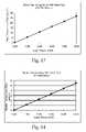
- FIG. 12is a plot illustrating the correlation between laser power and temperature of the reader without a heat pipe in accordance with one embodiment of the current invention
- FIG. 13is a plot illustrating the correlation between laser power and temperature of the write pole with a heat pipe in accordance with one embodiment of the current invention
- FIG. 14is a plot illustrating the correlation between laser power and temperature of the reader with a heat pipe in accordance with one embodiment of the current invention.
- FIG. 15is a flow chart for monitoring laser light power in accordance with one embodiment of the current invention.
- FIGS. 1 and 2show schematic diagrams of one embodiment of a data storage system in which the present invention may be deployed, which is designated by the general reference number 10 .
- the system 10may include a plurality of magnetic recording disks 12 .
- Each disk 12may have a plurality of concentric data tracks.
- the disks 12are typically mounted on a spindle motor shaft 14 , which may connect to a spindle motor 16 .
- the motor 16is typically mounted to a chassis 18 .
- the disks 12 , spindle 14 , and motor 16form a disk stack assembly 20 .
- a plurality of read/write heads 30may be positioned over the disks 12 such that at least one surface of each disk 12 has a corresponding head 30 .
- Each head 30may attach to one of a plurality of sliders 32 .
- Each slider 32may have a corresponding actuator arm 34 .
- Sliders 32are typically connected to a rotary actuator 36 .
- the actuator 36moves the heads in a radial direction across disks 12 .
- the actuator 36typically includes a rotating member 38 mounted to a rotating bearing 40 , a motor winding 42 , and motor magnets 44 .
- the actuator 36is also mounted to chassis 18 .
- the heads 30 , slider 32 and actuator 36form an actuator assembly 46 .
- the disk stack assembly 20 and the actuator assembly 46may be sealed in an enclosure 48 (shown by a dashed line), which provides protection from particulate contamination.
- a controller unit 50typically provides overall control to the system 10 .
- the controller unit 50may contain a central processing unit (CPU), memory unit and other digital circuitry.
- the controller 50may connect to an actuator control/drive unit 56 which in turn is connected to the actuator 36 . This allows the controller 50 to control the movement of the heads 30 over the disks 12 .
- the controller 50may be connected to a read/write channel 58 which in turn connects to the laser power monitor 62 .
- the laser power monitormay be connected to the heads 30 . This enables the controller 50 to send and receive data from the disks 12 including read/write data and laser output information.
- the controller 50may connect to a spindle control/drive unit 60 which in turn is connected to spindle motor 16 .
- a host system 70which is typically a computer system, may connect to the controller unit 50 .
- the system 70may send digital data to controller 50 to be stored on disks 12 , or may request the digital data be read from disks 12 and sent to the system 70 .
- FIG. 3depicts an embodiment of a read/write head 30 for use in thermally assisted magnetic recording.
- Read/write head elementsinclude a write coil 316 , write pole 314 and a read element 326 .
- read/write head elementsmay also include a thermal fly height control heater 328 .
- the read/write head 30may also include a laser 302 configured to emit a laser light 304 and a write pole 314 configured to write data to the magnetic recording disk 12 .
- the laser 302is electrically connected to read/write channel 58 by laser electrical leads 306 .
- the read write channel 58may provide electrical current to the laser electrical leads 306 when the system 70 requires data to be stored on disks 12 .
- the laser light 304may be configured to heat a hotspot 308 on the magnetic recording disks 12 corresponding to a magnetic bit 310 .
- magnetic bits 310have a higher magnetic anisotropy than magnetic bits used in conventional magnetic recording.
- Magnetic bits 310may comprise a plurality of magnetic grains having a field of magnetization 312 that points in a direction substantially horizontal to the magnetic recording disk 12 surface. While FIG.
- the magnetic recording disk 12comprises a longitudinal media
- the current inventionis equally applicable to perpendicular media where the grains each have a magnetic easy axis substantially perpendicular to the media surface, thereby allowing the magnetic grains to be vertically magnetized. Further, one skilled in the art will recognize that the current invention is equally applicable to tilted media wherein the magnetic easy axis of the grains are neither perpendicular nor horizontal to the media surface.
- a write pole 314may be disposed adjacent to the hotspot 304 on the magnetic recording disk 12 .
- the write pole 314may also be disposed adjacent to the laser light 304 and in certain embodiments, a portion of the laser light 304 may be absorbed by the write pole 314 causing the write pole 314 to heat up.
- the write pole 314may be coincident the laser light 304 .
- laser light 304may be disposed in a channel through the write pole 314 .
- Write coil 316is coupled to write coil electrical leads 318 .
- the read write channel 58may provide electrical current to the write coil electrical leads 318 when the system 70 requires data to be stored on disks 12 .
- the electrical current provided to the write coil electrical leads 318may be supplied simultaneously with the current supplied to the laser electrical leads 306 such that both the laser 302 and the write coil 316 are powered when the system 70 requires data to be stored on disks 12 .
- Applying an electrical current through write coil 316produces a magnetic field.
- the direction of the magnetic field produced by the write coil 316depends on the direction that the current is flowing through the magnetic coil 316 .
- This magnetic fieldis transferred to the write pole 314 as indicated by arrows 320 .
- a return path 324returns the magnetic field to the write coil 316 .
- the magnetic recording diskcompletes the magnetic circuit 322 which, in turn, orients the field of magnetization 312 of the magnetic bit 310 on the magnetic disk 12 .
- the laser 302may be powered to produce laser light 304 to heat the hotspot 308 such that the magnetic anisotropy of magnetic bits 310 is reduced.
- the write coil 316is powered and a magnetic circuit 322 is completed to orient the field of magnetization 312 of the magnetic bits 310 .
- the direction of flow of the magnetic circuit 322and thus the orientation of the magnetic bits 310 will depend on the direction of flow of the electrical current through the write coil 316 .
- the write pole 314is disposed in close enough proximity to the write coil 316 to be influenced by the write coil electrically induced magnetic field. This close proximity between the write pole 314 and the write coil 316 also results in thermal conduction between the write pole 314 and write coil 316 . Thus, as the write pole 314 absorbs laser light 304 and heats up, the write coil 316 also heats up. As heat increases in the write coil 316 , the electrical resistance to the write coil electrical leads 318 is increased.
- the laser power monitor 62may be configured to sense electrical resistance changes in the write coil electrical leads 318 .
- the laser power monitor 62may be configured to calculate laser power as a function of electrical resistance in the write coil electrical leads 318 .
- the laser power monitor 62may report the power of the laser light 304 to the controller unit 50 which in turn may increase or decrease electrical current to the laser. In another embodiment, the laser power monitor 62 may report the power of the laser light 304 to the host system 70 so that appropriate action may be taken such as replacing the laser 302 , if needed.
- a read element 326is disposed between a first magnetic shield 330 and a second magnetic shield 332 .
- the magnetic shields 330 and 332may be configured to shield the read element 326 from the magnetic circuit 322 produced by the write coils 316 .
- the read element 326may comprise an anisotropic magnetoresistive head.
- the read element 326may comprise a giant magnetoresistive head.
- the read element 326may comprise a tunnel-type magnetoresistive head.
- the read element 326is coupled to read element electrical leads 334 and is configured to produce a change in electrical resistance in response to the magnetic fields 312 of the magnetic bits on the magnetic recording disk 12 .
- the electrical resistance of the read element 326also changes in response to thermal changes in the temperature of the read element 326 . As the temperature rises, the electrical resistance of the read element 326 increases. To read data embedded on the magnetic recording disk 12 , the read element 326 may communicate electrical resistance changes to the read element electrical leads 334 . The electrical resistance change may be in response to the magnetic fields 312 of the individual magnetic bits 310 .
- the read element 326may be disposed in close enough proximity to the write pole 314 to be heated by the write pole 314 . Thus, as the write pole 314 absorbs laser light 304 and heats up, the read element 326 may also heat up. As heat increases in the read element 326 , the electrical resistance to the read element electrical leads 334 is increased.
- the laser power monitor 62may be configured to sense electrical resistance changes in the read element electrical leads 334 .
- the laser power monitormay be configured to calculate laser power as a function of electrical resistance in the read element electrical leads 334 .
- the laser power monitor 62may report the power of the laser light 304 to the controller unit 50 which in turn may increase or decrease electrical current to the laser. In another embodiment, the laser power monitor 62 may report the power of the laser light 304 to the host system 70 so that appropriate action may be taken such as replacing the laser 302 .
- a thermal fly height control heater (TFC heater) 328may be provided to maintain a minimum temperature within the read/write head 30 .
- the TFC heatermay be coupled to TFC heater electrical leads 336 .
- the electrical resistance of the TFC heater 328may change in response to thermal changes in the temperature of the TFC heater 328 . As the temperature rises, the electrical resistance of the TFC heater 328 increases.
- the TFC heater 328communicates electrical resistance changes to TFC heater electrical leads 336 which in turn may communicate the electrical resistance change to the laser power monitor 62 .
- the TFC heater 328may be disposed in close enough proximity to the write pole 314 to be heated by the write pole 314 . Thus, as the write pole 314 absorbs laser light 304 and heats up, the TFC heater 328 may also heat up. As heat increases in the TFC heater 328 , the electrical resistance to the TFC heater electrical leads 336 is increased.
- the laser power monitor 62may be configured to sense electrical resistance changes in the TFC heater electrical leads 336 .
- the laser power monitormay be configured to calculate laser power as a function of electrical resistance in the TFC heater electrical leads 336 .
- the laser power monitor 62may report the power of the laser light 304 to the controller unit 50 which in turn may increase or decrease electrical current to the laser. In another embodiment, the laser power monitor 62 may report the power of the laser light 304 to the host system 70 so that appropriate action may be taken such as replacing the laser 302 .
- the write coil electrical leads 318 , the read element electrical leads 334 and the TFC heater electrical leads 336are all coupled to the laser power monitor 62 which is in turn configured to monitor electrical resistance change in one or more of the read/write head elements.
- any one or more of the head elementsmay be coupled to the laser power monitor to provide an electrical resistance change in response to thermal fluctuations in the read/write head 30 .
- the laser power monitormay be configured to calculate laser power as a function of electrical resistance change.
- the laser power monitor 62may report the power of the laser light 304 to the controller unit 50 which in turn may increase or decrease electrical current to the laser.
- the laser power monitor 62may report the power of the laser light 304 to the host system 70 so that appropriate action may be taken such as replacing the laser 302 .
- FIG. 4illustrates a block diagram according one embodiment of the current invention.
- the write coil 316may be disposed around a laser light waveguide 402 and may be configured to surround the waveguide 402 .
- the waveguide 402may be disposed through the center of the write coil 316 and adjacent to the write pole 314 .
- the write pole 314may be arranged such that the write pole 314 partially blocks the laser light 304 in the waveguide 402 .
- the waveguide 402may be configured to convey laser light 304 from the laser 302 to the hotspot 308 on the magnetic recording medium 12 .
- the waveguide 402may comprise a dielectric material that will convey the laser light 304 without absorbing heat.
- FIG. 5illustrates laser light intensity across one embodiment of a waveguide 402 .
- Laser light intensityis at its maximum 502 at the center of the waveguide 402 and tapers off toward the edges 506 of the waveguide. As shown in FIG. 5 , the laser light intensity is generally not zero immediately outside waveguide, but exhibits tails 504 .
- a metallic element, such as write pole 314 or other metallic object disposed adjacent to the waveguide 402absorbs the laser light 304 of tails 504 and converts the laser light 304 into heat.
- a heat absorbing sensor 602may be disposed within the read/write head 30 , in certain embodiments.
- the heat absorbing sensor 602may be coupled to heat absorbing sensor electrical leads 604 .
- the heat absorbing sensor 602may be positioned in close enough proximity to the waveguide 402 to absorb a tail 504 of laser light 304 .
- the heat absorbing sensor 602may be disposed in close proximity to the write pole 314 to absorb heat from the write pole 314 .
- the heat absorbing sensor 602may also heat up.
- the electrical resistance to the heat absorbing sensor electrical leads 604may increased.
- the heat absorbing sensor electrical leads 604may be coupled to the laser power monitor 62 .
- the laser power monitor 62may sense electrical resistance changes in the heat absorbing sensor electrical leads 604 .
- the laser power monitor 62may calculate laser power as a function of electrical resistance in the heat absorbing sensor electrical leads 604 .
- the laser power monitor 62reports the power of the laser light 304 to the controller unit 50 which in turn may increase or decrease electrical current to the laser 302 .
- the laser power monitor 62reports the power of the laser light 304 to the host system 70 so that appropriate action may be taken such as replacing the laser 302 .
- the power of the laser light 304 detected by the laser power monitor 62may be very low or zero indicating that the laser 302 is inoperative.
- the heat absorbing sensor 602may include a finger 702 .
- the finger 702may comprise a thermal conductive material such as metal.
- the finger 702may connect to or be intergrated with the heat absorbing sensor 602 .
- the finger 702may partially extend into the waveguide 402 to absorb laser light 304 .
- FIG. 7 billustrates a read/write head 30 with a near-field aperture structure 706 according to one embodiment of the current invention.
- the waveguide 402may propagate laser light 304 several hundred nanometers in diameter to a hotspot 308 (see FIG. 3 ) on the magnetic recording disk 12 .
- a near-field aperture structure 706is positioned in close proximity to the magnetic write pole 314 .
- the near-field aperture structure 706is disposed around the write pole 314 .
- a dielectric materialmay be disposed within a void 708 in the aperture structure 706 and around the write pole 314 .
- the dielectric materialmay comprise a material with a high optical index of refraction to allow the propagation of light through the aperture structure 706 .
- the void 708 of the near-field aperture structure 706is filled with a transparent material such that laser light 304 propagates through the transparent material.
- laser light 304propagates to the surface of the aperture structure 706 through the wave guide 402 , some laser light 304 is absorbed by and heats the aperture structure 706 .
- the laser light that passes through the near-field aperture structure 706is narrowed due to the structure of the near-field aperture.
- the resulting laser light 304 passing through the aperture structure 706is narrowed to about 30 to 50 nanometers in diameter.
- the shape of the void 708 disposed within the aperture structure 706may be C-shaped, square, rectangular, circular or any other shape as is known in the art.
- the void 706 in the near-field aperture structure 706may not contain a dielectric material or transparent material but rather may be empty.
- aperture structure electrical leads 710may be electrically coupled to the near-field aperture structure 706 at one end, and the laser intensity monitor 62 at the other end.
- the temperature of the near-field aperture structure 706rises.
- the electrical resistance to the aperture structure electrical leads 710increases.
- the laser intensity monitor 62senses electrical resistance changes in the aperture structure electrical leads 710 .
- the laser intensity monitor 62calculates laser intensity as a function of electrical resistance in the aperture structure electrical leads 610 .
- the laser intensity monitor 62reports the intensity of the laser light 304 to the controller unit 50 which in turn increases or decreases electrical current to the laser 302 .
- the laser intensity monitor 62reports the intensity of the laser light 304 to the host system 70 so that appropriate action may be taken such as replacing the laser 302 .
- the intensity of the laser light 304 detected by the laser intensity monitor 62may be very low or zero indicating that the laser 302 is inoperative.
- FIG. 8illustrates a schematic block diagram according to one embodiment of the current invention.
- a heat pipe 802is positioned around the write pole 314 in certain embodiments.
- the heat pipe 802conducts heat from the write pole 314 or hotspot 308 to the write coil 316 or other electrically coupled head element.
- the heat pipeconducts heat from the near-field aperture structure 706 to the write coil 316 or other electrically coupled head element.
- the heat pipe 802may comprise a heat conductive element such as copper or other metallic material.
- a read/write head elementmeasures a first electrical resistance of one or more read/write head elements when the slider 32 is on a load/unload ramp.
- a laser 302heats the head elements either directly or indirectly.
- the head elementmeasures a second electrical resistance of the head element at regular intervals when the slider 32 is on the load/unload ramp.
- the electrical resistance measurementsare conducted while the slider 32 and read/write head 30 are flying on the disk. Temperature sensitivity is reduced due to cooling of the air bearing on the disk. This embodiment can provide a continuous or nearly continuous monitoring of laser power.
- FIG. 9is a graphical illustration of electrical resistance calculations at regular intervals with the read/write head 30 on the ramp.
- the embodiment illustrated in FIG. 9does not utilize a heat pipe 802 .
- the electrical resistance 904 in the head elementincreases along the y axis.
- Line 906illustrates electrical resistance change in the write coil 316 as a function of laser power.
- Line 908illustrates electrical resistance change in the TFC heater 328 as function of laser power. The difference in the slope of lines 906 and 908 may be due to the greater physical distance of the TFC heater 328 from the write pole 314 .
- the TFC heater 328may be positioned closer to the write pole 314 such that the TFC heater 328 may absorb more heat and at a faster rate than the illustrated embodiment.
- This graphillustrates that electrical resistance rise is proportional to the power of the laser.
- the write coil 316has an electrical resistance increase approximately 2.25 times the electrical resistance of the TFC heater 328 .
- the electrical resistance of the write coil 316 when the write coil 316 is coldis about 3.5 ⁇
- the electrical resistance of the TFC heater 328 when the TFC heater 328 is coldis about 120 ⁇ .
- FIG. 10is another graphical illustration of electrical resistance calculations at regular intervals with the read/write head 30 on the ramp.
- the embodiment illustrated in FIG. 10utilizes a heat pipe 802 .
- the electrical resistance 1004 in the head elementincreases along the y axis.
- Line 1006illustrates electrical resistance change in the write coil 316 as a function of laser power.
- Line 1008illustrates electrical resistance change in the TFC heater 328 as function of laser power. The difference in the slope of lines 1006 and 1008 may be due to the greater distance of the TFC heater 328 from the write pole 314 .
- the TFC heater 328may be disposed closer to the write pole 314 so that the TFC heater 328 absorbs more heat and at a faster rate.
- This graphillustrates that electrical resistance rise is proportional to power of the laser.
- the write coil 316has an electrical resistance increase approximately 2.25 times the electrical resistance of the TFC heater 328 .
- the electrical resistance of the write coil 316 when the write coil 316 is coldis about 3.5 ⁇
- the electrical resistance of the TFC heater 328 when the TFC heater 328 is coldis about 120 ⁇ .
- FIG. 11is a graphical illustration of temperature rise as the laser 302 heats the write pole 314 .
- the temperature calculationsoccur at regular intervals with the read/write head 30 on the ramp.
- the embodiment illustrated in FIG. 11does not utilize a heat pipe 802 .
- This graphillustrates that temperature rises at the write pole 314 is proportional to laser power.
- the temperature rise of the write pole 314is about 6.4° C./1 mW of power absorbed from the laser light 304 . Absorbed power is expected to be in the 1-100 mW range.
- FIG. 12is a graphical illustration of temperature rise calculations at the read element 326 as the laser 302 heats the read element 326 .
- the temperature calculationsoccur at regular intervals with the read/write head 30 on the ramp.
- the embodiment illustrated in FIG. 12does not utilize a heat pipe 802 .
- This graphillustrates that temperature rises at the read element 326 is proportional to laser power.
- the temperature rise of the read element 326is about 1.2° C./1 mW of power absorbed from the laser light 304 . Absorbed power is expected to be in the 1-100 mW range.
- FIG. 13is a graphical illustration of temperature rise calculations at the write pole 314 as the laser 302 heats the write pole 314 .
- the temperature calculationsoccur at regular intervals with the read/write head 30 on the ramp.
- the difference between FIG. 11 and the embodiment illustrated in FIG. 13is FIG. 13 does utilize a heat pipe 802 .
- This graphillustrates that temperature rises at the write pole 314 is proportional to laser power.
- the temperature rise of the write pole 314is about 5.3° C./1 mW of power absorbed from the laser light 304 . This is lower than where a heat pipe 802 is not utilized.
- FIG. 14is a graphical illustration of temperature rise calculations at the read element 326 at regular intervals with the read/write head 30 on the ramp.
- the difference between FIG. 12 and the embodiment illustrated in FIG. 14is FIG. 14 does utilize a heat pipe 802 .
- This graphillustrates that temperature rises at the read element 326 is proportional to laser power.
- the temperature rise of the read element 326is about 1.1° C./1 mW of power absorbed from the laser light 304 . This is lower than where a heat pipe 802 is not utilized.
- FIG. 15is a flow chart of an embodiment of one possible method 1500 of monitoring the power of laser light 304 .
- a read/write head elementis provided 1502 and coupled to an electrical lead, the electrical lead is coupled to laser power monitor 62 .
- the read/write head elementmay comprise a write coil 316 , a read element 326 , TFC heater 328 , heat absorbing sensor 602 or other electrically coupled head element.
- An electrical currentis applied 1504 to the electrical leads coupled to the read/write head element.
- a first electrical resistanceis measured 1506 in the read/write head element.
- a laser 302is signaled 1508 to generate laser light 304 .
- the read/write head elementis heated 1510 by laser light 304 .
- the read/write head elementmay be directly heated by the laser light 304 or the read/write head element may be heated by a tail 504 of laser light.
- a second electrical resistanceis measured 1512 in the read/write head element.
- the power of laser light 304is determined 1514 .
- the laser powermay be reported 1516 to the read/write channel 58 .
- the measurement of the first electrical resistance 1506 and the measurement of the second electrical resistance 1512may be measured at regular intervals when the slider 32 is on the load/unload ramp. In one embodiment the measurement of the first electrical resistance 1506 and the measurement of the second electrical resistance 1512 may be measured at regular intervals when the slider 32 is flying over the magnetic recording medium 12 . In one embodiment the measurement of the first electrical resistance 1506 and the measurement of the second electrical resistance 1512 may be measured continuously while the slider 32 is flying over the magnetic recording medium 12 .
Landscapes
- Physics & Mathematics (AREA)
- Electromagnetism (AREA)
- Engineering & Computer Science (AREA)
- Manufacturing & Machinery (AREA)
- Recording Or Reproducing By Magnetic Means (AREA)
- Magnetic Heads (AREA)
Abstract
Description
Claims (25)
Priority Applications (1)
| Application Number | Priority Date | Filing Date | Title |
|---|---|---|---|
| US12/042,230US8406090B2 (en) | 2008-03-04 | 2008-03-04 | Laser power sensor for thermally assisted magnetic recording |
Applications Claiming Priority (1)
| Application Number | Priority Date | Filing Date | Title |
|---|---|---|---|
| US12/042,230US8406090B2 (en) | 2008-03-04 | 2008-03-04 | Laser power sensor for thermally assisted magnetic recording |
Publications (2)
| Publication Number | Publication Date |
|---|---|
| US20090225464A1 US20090225464A1 (en) | 2009-09-10 |
| US8406090B2true US8406090B2 (en) | 2013-03-26 |
Family
ID=41053358
Family Applications (1)
| Application Number | Title | Priority Date | Filing Date |
|---|---|---|---|
| US12/042,230Active2029-06-13US8406090B2 (en) | 2008-03-04 | 2008-03-04 | Laser power sensor for thermally assisted magnetic recording |
Country Status (1)
| Country | Link |
|---|---|
| US (1) | US8406090B2 (en) |
Cited By (21)
| Publication number | Priority date | Publication date | Assignee | Title |
|---|---|---|---|---|
| US8743667B1 (en)* | 2013-02-26 | 2014-06-03 | HGST Netherlands B.V. | Method for controlling writing in a thermally-assisted recording (TAR) disk drive with thermal fly-height control |
| US8908483B1 (en) | 2014-05-30 | 2014-12-09 | HGST Netherlands B.V. | Implementing contact sensing with near field transducer (NFT) and in-drive NFT characterization diagnostics in heat-assisted magnetic recording (HAMR) HDD |
| US8923101B1 (en) | 2013-09-17 | 2014-12-30 | Seagate Technology Llc | Monolithically integrated laser diode and power monitor |
| US8958271B1 (en) | 2013-09-03 | 2015-02-17 | Seagate Technology Llc | Peg height of near-field transducers |
| US9042210B2 (en) | 2013-09-26 | 2015-05-26 | Seagate Technology Llc | Multi-purpose near-field transducer having a temperature coefficient of resistance |
| US9047926B2 (en) | 2013-10-18 | 2015-06-02 | HGST Netherlands B.V. | Dual thermal sensor for HAMR waveguide power monitor and integration with the contact sensor |
| US9099144B1 (en) | 2013-10-11 | 2015-08-04 | Western Digital Technologies, Inc. | Disk drive evaluating laser performance for heat assisted magnetic recording |
| US9117474B1 (en)* | 2014-10-02 | 2015-08-25 | HGST Netherlands B.V. | Implementing write head device for contact detection and spacing sensing |
| US9153272B1 (en) | 2014-05-15 | 2015-10-06 | Seagate Technology Llc | Characterizing laser output in a HAMR device |
| US9165591B2 (en) | 2013-08-07 | 2015-10-20 | Seagate Technology Llc | Grating based laser and power monitor for a heat-assisted magnetic recording device |
| US9202487B2 (en) | 2013-04-10 | 2015-12-01 | Seagate Technology Llc | Light source alignment for heat assisted magnetic recording |
| US9236081B1 (en) | 2015-03-31 | 2016-01-12 | Seagate Technology Llc | Laser temperature calibration in a HAMR device |
| US9245553B2 (en) | 2013-11-25 | 2016-01-26 | HGST Netherlands B.V. | Submount-integrated photodetector for monitoring a laser for a heat-assisted magnetic recording head |
| US9291560B2 (en) | 2012-04-24 | 2016-03-22 | Seagate Technology Llc | Characterization of near field transducers |
| US9311943B2 (en) | 2014-02-17 | 2016-04-12 | HGST Netherlands B.V. | Compensation of laser diode introduced flying height changes |
| US9355671B2 (en) | 2014-05-15 | 2016-05-31 | Seagate Technology Llc | Controlling laser output in a HAMR device |
| US9472229B1 (en) | 2015-04-16 | 2016-10-18 | Seagate Technology Llc | Adaptive laser output control in a HAMR device |
| US9613643B2 (en) | 2013-08-05 | 2017-04-04 | Seagate Technology Llc | Alignment of optical components |
| US9620162B1 (en) | 2016-03-31 | 2017-04-11 | Western Digital Technologies, Inc. | Data storage device boosting prelase bias while over data sector for heat assisted magnetic recording |
| US10770106B1 (en) | 2019-12-23 | 2020-09-08 | Seagate Technology Llc | System and method using on-ramp heating to detect laser mode hopping in heat assisted recording |
| US20240331729A1 (en)* | 2023-03-30 | 2024-10-03 | Western Digital Technologies, Inc. | Data storage device with intelligent write protection for energy anomalies in energy-assisted magnetic recording |
Families Citing this family (32)
| Publication number | Priority date | Publication date | Assignee | Title |
|---|---|---|---|---|
| US9508368B2 (en)* | 2010-03-19 | 2016-11-29 | Seagate Technology Llc | Slider for heat assisted magnetic recording including a thermal sensor for monitoring laser power |
| US8391107B2 (en)* | 2010-03-19 | 2013-03-05 | Seagate Technology Llc | Slider for heat assisted magnetic recording including a photo detector for monitoring laser power |
| US8369191B2 (en)* | 2010-11-29 | 2013-02-05 | Tdk Corporation | Method for controlling the current of laser diode on thermally assisted magnetic recording head |
| US8374059B2 (en)* | 2011-03-11 | 2013-02-12 | Tdk Corporation | Heat-assisted magnetic write head, head gimbals assembly, head arm assembly, and magnetic disk device |
| US8897103B2 (en) | 2011-09-27 | 2014-11-25 | Western Digital Technologies, Inc. | Disk drive calibrating a laser write power for heat assisted magnetic recording |
| US8787126B2 (en)* | 2011-10-10 | 2014-07-22 | Seagate Technology Llc | Waveguide with blocking layer |
| US8451696B2 (en) | 2011-10-31 | 2013-05-28 | HGST Netherlands B.V. | Temperature sensor in a thermally assisted magnetic recording head |
| US8705323B2 (en) | 2011-10-31 | 2014-04-22 | HGST Netherlands B.V. | TAR temperature sensor having faster response time |
| US8553506B2 (en) | 2011-12-29 | 2013-10-08 | HGST Netherlands B.V. | Preheat feature for thermally assisted recording |
| JP5823300B2 (en)* | 2012-01-05 | 2015-11-25 | 株式会社東芝 | Magnetic recording head and magnetic recording / reproducing apparatus |
| US8456980B1 (en) | 2012-03-13 | 2013-06-04 | Western Digital Technologies, Inc. | Disk drive compensating for laser induced head protrusion in heat assisted magnetic recording |
| US8441909B1 (en) | 2012-03-13 | 2013-05-14 | Western Digital Technologies, Inc. | Disk drive increasing laser power at beginning of write in heat assisted magnetic recording |
| US9318142B2 (en) | 2012-04-25 | 2016-04-19 | Seagate Technology Llc | Laser modulation for magnetic recording apparatus |
| US8619508B1 (en) | 2012-07-23 | 2013-12-31 | Western Digital Technologies, Inc. | Disk drive adjusting fly height actuator to compensate for laser induced head protrusion in heat assisted magnetic recording |
| US8854929B1 (en) | 2013-03-06 | 2014-10-07 | Western Digital Technologies, Inc. | Disk drive calibrating laser power and write current for heat assisted magnetic recording |
| US9202499B2 (en)* | 2013-03-13 | 2015-12-01 | Seagate Technology Llc | Contact detection using laser modulation |
| US8787125B1 (en) | 2013-03-13 | 2014-07-22 | Western Digital Technologies, Inc. | Disk drive calibrating fly height actuator to enable laser biasing during non-write mode |
| US9074941B1 (en) | 2013-03-14 | 2015-07-07 | Western Digital Technologies, Inc. | Systems and methods for measuring ambient and laser temperature in heat assisted magnetic recording |
| US8861124B1 (en)* | 2013-03-14 | 2014-10-14 | Western Digital (Fremont), Llc | Integrated sensor for monitoring laser power in a heat assisted magnetic recording disk drive |
| US8902718B1 (en) | 2013-05-21 | 2014-12-02 | Western Digital Technologies, Inc. | Disk drive calibrating dynamic fly height write profile for fly height actuator |
| US8842383B1 (en) | 2013-05-31 | 2014-09-23 | HGST Netherlands B.V. | Laser power sensor with dual temperature sensor |
| US8922929B1 (en) | 2013-06-13 | 2014-12-30 | Western Digital Technologies, Inc. | Disk drive calibrating fly height actuator and laser power for heat assisted magnetic recording |
| US9153276B2 (en) | 2013-07-30 | 2015-10-06 | Seagate Technology Llc | Laser optical power monitoring using thermal sensor of a head transducer |
| US8842507B1 (en) | 2013-10-22 | 2014-09-23 | HGST Netherlands B.V. | Heat-assisted magnetic recording disk drive (HAMR) with thermal sensor and laser power prediction |
| US9202488B2 (en)* | 2014-01-09 | 2015-12-01 | Seagate Technology Llc | Light blocker for stray light reduction within a slider |
| US9318153B2 (en)* | 2014-03-31 | 2016-04-19 | Seagate Technology Llc | HAMR drive fault detection system |
| US9087546B1 (en)* | 2014-05-06 | 2015-07-21 | HGST Netherlands B.V. | Combined micro heater and waveguide power sensor for heat-assisted magnetic recording |
| US9747928B1 (en) | 2014-09-25 | 2017-08-29 | Western Digital Technologies, Inc. | Data storage device modifying write operation when a laser mode hop is detected |
| US9336831B2 (en) | 2014-10-10 | 2016-05-10 | Seagate Technology Llc | HAMR drive fault detection system |
| US9495995B1 (en)* | 2015-08-25 | 2016-11-15 | Seagate Technology Llc | Adjusting laser power to achieve equivalent track spacing for paired heads that simultaneously write to a heat-assisted recording medium |
| US10127940B1 (en)* | 2015-11-06 | 2018-11-13 | Seagate Technology Llc | Bolometer with temperature compensation for internal laser power monitoring in heat-assisted magnetic recording device |
| US9653121B1 (en) | 2016-03-18 | 2017-05-16 | Seagate Technology Llc | Heat-assisted magnetic recording device capable of detecting head malfunction based on different currents of sensors |
Citations (34)
| Publication number | Priority date | Publication date | Assignee | Title |
|---|---|---|---|---|
| JPS61214266A (en) | 1985-03-20 | 1986-09-24 | Hitachi Ltd | Magneto-optical recording/reproducing device |
| JPS6321887A (en) | 1986-07-15 | 1988-01-29 | Fuji Photo Film Co Ltd | Light source for semiconductor laser |
| JPH04175616A (en) | 1990-11-07 | 1992-06-23 | Nec Corp | Laser beam monitoring device |
| JPH04221438A (en) | 1990-12-21 | 1992-08-11 | Mitsubishi Electric Corp | Laser power measurement jig for optical disk devices |
| US5274622A (en)* | 1991-11-19 | 1993-12-28 | Pioneer Electronic Corporation | Apparatus for controlling emission power of laser diode |
| US5313444A (en)* | 1991-11-18 | 1994-05-17 | Sharp Kabushiki Kaisha | External magnetic field generation apparatus capable of light intensity modulation and magnetic field modulation |
| JPH08106669A (en) | 1994-10-07 | 1996-04-23 | Sanyo Electric Co Ltd | Detecting circuit for temperature of disk of magneto-optical disk player |
| US5944882A (en)* | 1996-09-04 | 1999-08-31 | Mitsubishi Chemical Corporation | Thermal transfer recording material |
| US6205849B1 (en)* | 1997-08-18 | 2001-03-27 | Seagate Technology Llc | Glide head using an ion etched air bearing |
| US6243350B1 (en)* | 1996-05-01 | 2001-06-05 | Terastor Corporation | Optical storage systems with flying optical heads for near-field recording and reading |
| WO2001063603A1 (en) | 2000-02-23 | 2001-08-30 | Sanyo Electric Co., Ltd. | Disk drive |
| US20020009105A1 (en)* | 1999-12-09 | 2002-01-24 | Kenji Matsumoto | Light emitting device |
| US20020012205A1 (en)* | 2000-07-28 | 2002-01-31 | Kenchi Ito | Magnetic head, magnetic recording and reproducing apparatus, method for reproducing and recording magnetic recording information |
| US20020135940A1 (en)* | 1998-11-13 | 2002-09-26 | Tdk Corporation | Write/read head supporting mechanism, and write/read system |
| US20020141118A1 (en)* | 2001-03-28 | 2002-10-03 | Hitachi, Ltd. | Magnetic head and production method for magnetic heads |
| US6552980B2 (en)* | 2000-06-29 | 2003-04-22 | Sony Corporation | Method of setting power for a reproducing beam to be applied to a magneto-optical disc, and method of reproducing data from a magneto-optical disc |
| US6671232B1 (en)* | 2001-07-25 | 2003-12-30 | Maxtor Corporation | Method and apparatus for measuring the surface temperature of a disk |
| US6671248B2 (en)* | 2000-05-18 | 2003-12-30 | Matsushita Electric Industrial Co., Ltd. | Apparatus and method of controlling laser power |
| US20040008591A1 (en) | 2002-06-24 | 2004-01-15 | Seagate Technology Llc | Recording pole for delivering coincident heat and magnetic field |
| US6798728B2 (en) | 2001-11-26 | 2004-09-28 | Hitachi, Ltd. | Optical disk device and luminescent power control method for semiconductor laser |
| US20050013034A1 (en)* | 2003-07-15 | 2005-01-20 | Margulies David T. | Method for magnetic recording on laminated media with improved media signal-to-noise ratio |
| US6853657B2 (en)* | 2000-08-08 | 2005-02-08 | Infineon Technologies Ag | Method and device for determining the output power of a semiconductor laser diode |
| JP2005122798A (en) | 2003-10-15 | 2005-05-12 | Sanyo Electric Co Ltd | Optical disk device and its control method |
| US6950260B2 (en) | 2001-06-04 | 2005-09-27 | Hitachi Global Technologies Netherlands B.V. | Thermally assisted magnetic recording system and method of writing using magnetic and thermal gradients |
| US20050213436A1 (en) | 2004-03-29 | 2005-09-29 | Sharp Kabushiki Kaisha | Read/write device, storage medium, driving method of read/write device, semiconductor laser life estimation method, program, program storage medium, and semiconductor laser |
| US20050265409A1 (en) | 2004-05-27 | 2005-12-01 | Lite-On It Corp. | Laser emitting device of optical disc drive |
| US20060117333A1 (en) | 2004-11-30 | 2006-06-01 | Fujitsu Limited | Heat-assisted magnetic recording method and test record reproduction method |
| US7077564B2 (en) | 2003-06-18 | 2006-07-18 | Coherent, Inc. | Laser power meter |
| US20070171805A1 (en) | 2005-12-28 | 2007-07-26 | Hitachi, Ltd. | Optical disc apparatus and laser power control method |
| US20070279791A1 (en)* | 2006-05-11 | 2007-12-06 | Seagate Technology Llc | Media for heat assisted magnetic recording |
| US20080056073A1 (en)* | 2006-08-30 | 2008-03-06 | Junichiro Shimizu | Recording head |
| JP4175616B2 (en) | 2002-12-05 | 2008-11-05 | 矢崎総業株式会社 | Lamp drive device |
| JP4221438B2 (en) | 2007-01-05 | 2009-02-12 | 三菱樹脂株式会社 | Drainage |
| US20090196128A1 (en)* | 2008-01-31 | 2009-08-06 | Lille Jeffrey S | Thermally assisted recording systems with low loss light redirection structure |
- 2008
- 2008-03-04USUS12/042,230patent/US8406090B2/enactiveActive
Patent Citations (34)
| Publication number | Priority date | Publication date | Assignee | Title |
|---|---|---|---|---|
| JPS61214266A (en) | 1985-03-20 | 1986-09-24 | Hitachi Ltd | Magneto-optical recording/reproducing device |
| JPS6321887A (en) | 1986-07-15 | 1988-01-29 | Fuji Photo Film Co Ltd | Light source for semiconductor laser |
| JPH04175616A (en) | 1990-11-07 | 1992-06-23 | Nec Corp | Laser beam monitoring device |
| JPH04221438A (en) | 1990-12-21 | 1992-08-11 | Mitsubishi Electric Corp | Laser power measurement jig for optical disk devices |
| US5313444A (en)* | 1991-11-18 | 1994-05-17 | Sharp Kabushiki Kaisha | External magnetic field generation apparatus capable of light intensity modulation and magnetic field modulation |
| US5274622A (en)* | 1991-11-19 | 1993-12-28 | Pioneer Electronic Corporation | Apparatus for controlling emission power of laser diode |
| JPH08106669A (en) | 1994-10-07 | 1996-04-23 | Sanyo Electric Co Ltd | Detecting circuit for temperature of disk of magneto-optical disk player |
| US6243350B1 (en)* | 1996-05-01 | 2001-06-05 | Terastor Corporation | Optical storage systems with flying optical heads for near-field recording and reading |
| US5944882A (en)* | 1996-09-04 | 1999-08-31 | Mitsubishi Chemical Corporation | Thermal transfer recording material |
| US6205849B1 (en)* | 1997-08-18 | 2001-03-27 | Seagate Technology Llc | Glide head using an ion etched air bearing |
| US20020135940A1 (en)* | 1998-11-13 | 2002-09-26 | Tdk Corporation | Write/read head supporting mechanism, and write/read system |
| US20020009105A1 (en)* | 1999-12-09 | 2002-01-24 | Kenji Matsumoto | Light emitting device |
| WO2001063603A1 (en) | 2000-02-23 | 2001-08-30 | Sanyo Electric Co., Ltd. | Disk drive |
| US6671248B2 (en)* | 2000-05-18 | 2003-12-30 | Matsushita Electric Industrial Co., Ltd. | Apparatus and method of controlling laser power |
| US6552980B2 (en)* | 2000-06-29 | 2003-04-22 | Sony Corporation | Method of setting power for a reproducing beam to be applied to a magneto-optical disc, and method of reproducing data from a magneto-optical disc |
| US20020012205A1 (en)* | 2000-07-28 | 2002-01-31 | Kenchi Ito | Magnetic head, magnetic recording and reproducing apparatus, method for reproducing and recording magnetic recording information |
| US6853657B2 (en)* | 2000-08-08 | 2005-02-08 | Infineon Technologies Ag | Method and device for determining the output power of a semiconductor laser diode |
| US20020141118A1 (en)* | 2001-03-28 | 2002-10-03 | Hitachi, Ltd. | Magnetic head and production method for magnetic heads |
| US6950260B2 (en) | 2001-06-04 | 2005-09-27 | Hitachi Global Technologies Netherlands B.V. | Thermally assisted magnetic recording system and method of writing using magnetic and thermal gradients |
| US6671232B1 (en)* | 2001-07-25 | 2003-12-30 | Maxtor Corporation | Method and apparatus for measuring the surface temperature of a disk |
| US6798728B2 (en) | 2001-11-26 | 2004-09-28 | Hitachi, Ltd. | Optical disk device and luminescent power control method for semiconductor laser |
| US20040008591A1 (en) | 2002-06-24 | 2004-01-15 | Seagate Technology Llc | Recording pole for delivering coincident heat and magnetic field |
| JP4175616B2 (en) | 2002-12-05 | 2008-11-05 | 矢崎総業株式会社 | Lamp drive device |
| US7077564B2 (en) | 2003-06-18 | 2006-07-18 | Coherent, Inc. | Laser power meter |
| US20050013034A1 (en)* | 2003-07-15 | 2005-01-20 | Margulies David T. | Method for magnetic recording on laminated media with improved media signal-to-noise ratio |
| JP2005122798A (en) | 2003-10-15 | 2005-05-12 | Sanyo Electric Co Ltd | Optical disk device and its control method |
| US20050213436A1 (en) | 2004-03-29 | 2005-09-29 | Sharp Kabushiki Kaisha | Read/write device, storage medium, driving method of read/write device, semiconductor laser life estimation method, program, program storage medium, and semiconductor laser |
| US20050265409A1 (en) | 2004-05-27 | 2005-12-01 | Lite-On It Corp. | Laser emitting device of optical disc drive |
| US20060117333A1 (en) | 2004-11-30 | 2006-06-01 | Fujitsu Limited | Heat-assisted magnetic recording method and test record reproduction method |
| US20070171805A1 (en) | 2005-12-28 | 2007-07-26 | Hitachi, Ltd. | Optical disc apparatus and laser power control method |
| US20070279791A1 (en)* | 2006-05-11 | 2007-12-06 | Seagate Technology Llc | Media for heat assisted magnetic recording |
| US20080056073A1 (en)* | 2006-08-30 | 2008-03-06 | Junichiro Shimizu | Recording head |
| JP4221438B2 (en) | 2007-01-05 | 2009-02-12 | 三菱樹脂株式会社 | Drainage |
| US20090196128A1 (en)* | 2008-01-31 | 2009-08-06 | Lille Jeffrey S | Thermally assisted recording systems with low loss light redirection structure |
Non-Patent Citations (2)
| Title |
|---|
| Hu et al., "Laser Irradiation and Its Effects on Heat Transfer in Heat Assisted Magnetic Recording", Review of Scientific Instruments 77, 034703, 2006. |
| Matteo et al., "Spectral Analysis of Strongly Enhanced Visible Light Transmission Through Single C-Shaped Nanoapertures", Applied Physics Letters, vol. 85, No. 4, Jul. 26, 2004. |
Cited By (23)
| Publication number | Priority date | Publication date | Assignee | Title |
|---|---|---|---|---|
| US9291560B2 (en) | 2012-04-24 | 2016-03-22 | Seagate Technology Llc | Characterization of near field transducers |
| US8743667B1 (en)* | 2013-02-26 | 2014-06-03 | HGST Netherlands B.V. | Method for controlling writing in a thermally-assisted recording (TAR) disk drive with thermal fly-height control |
| US9202487B2 (en) | 2013-04-10 | 2015-12-01 | Seagate Technology Llc | Light source alignment for heat assisted magnetic recording |
| US9613643B2 (en) | 2013-08-05 | 2017-04-04 | Seagate Technology Llc | Alignment of optical components |
| US9165591B2 (en) | 2013-08-07 | 2015-10-20 | Seagate Technology Llc | Grating based laser and power monitor for a heat-assisted magnetic recording device |
| US8958271B1 (en) | 2013-09-03 | 2015-02-17 | Seagate Technology Llc | Peg height of near-field transducers |
| US9396748B2 (en) | 2013-09-03 | 2016-07-19 | Seagate Technology Llc | Peg height of near-field transducers |
| US8923101B1 (en) | 2013-09-17 | 2014-12-30 | Seagate Technology Llc | Monolithically integrated laser diode and power monitor |
| US9042210B2 (en) | 2013-09-26 | 2015-05-26 | Seagate Technology Llc | Multi-purpose near-field transducer having a temperature coefficient of resistance |
| US9177577B2 (en) | 2013-09-26 | 2015-11-03 | Seagate Technology Llc | Multi-purpose near-field transducer having a temperature coefficient of resistance |
| US9099144B1 (en) | 2013-10-11 | 2015-08-04 | Western Digital Technologies, Inc. | Disk drive evaluating laser performance for heat assisted magnetic recording |
| US9047926B2 (en) | 2013-10-18 | 2015-06-02 | HGST Netherlands B.V. | Dual thermal sensor for HAMR waveguide power monitor and integration with the contact sensor |
| US9245553B2 (en) | 2013-11-25 | 2016-01-26 | HGST Netherlands B.V. | Submount-integrated photodetector for monitoring a laser for a heat-assisted magnetic recording head |
| US9311943B2 (en) | 2014-02-17 | 2016-04-12 | HGST Netherlands B.V. | Compensation of laser diode introduced flying height changes |
| US9153272B1 (en) | 2014-05-15 | 2015-10-06 | Seagate Technology Llc | Characterizing laser output in a HAMR device |
| US9355671B2 (en) | 2014-05-15 | 2016-05-31 | Seagate Technology Llc | Controlling laser output in a HAMR device |
| US8908483B1 (en) | 2014-05-30 | 2014-12-09 | HGST Netherlands B.V. | Implementing contact sensing with near field transducer (NFT) and in-drive NFT characterization diagnostics in heat-assisted magnetic recording (HAMR) HDD |
| US9117474B1 (en)* | 2014-10-02 | 2015-08-25 | HGST Netherlands B.V. | Implementing write head device for contact detection and spacing sensing |
| US9236081B1 (en) | 2015-03-31 | 2016-01-12 | Seagate Technology Llc | Laser temperature calibration in a HAMR device |
| US9472229B1 (en) | 2015-04-16 | 2016-10-18 | Seagate Technology Llc | Adaptive laser output control in a HAMR device |
| US9620162B1 (en) | 2016-03-31 | 2017-04-11 | Western Digital Technologies, Inc. | Data storage device boosting prelase bias while over data sector for heat assisted magnetic recording |
| US10770106B1 (en) | 2019-12-23 | 2020-09-08 | Seagate Technology Llc | System and method using on-ramp heating to detect laser mode hopping in heat assisted recording |
| US20240331729A1 (en)* | 2023-03-30 | 2024-10-03 | Western Digital Technologies, Inc. | Data storage device with intelligent write protection for energy anomalies in energy-assisted magnetic recording |
Also Published As
| Publication number | Publication date |
|---|---|
| US20090225464A1 (en) | 2009-09-10 |
Similar Documents
| Publication | Publication Date | Title |
|---|---|---|
| US8406090B2 (en) | Laser power sensor for thermally assisted magnetic recording | |
| US8451696B2 (en) | Temperature sensor in a thermally assisted magnetic recording head | |
| US8705323B2 (en) | TAR temperature sensor having faster response time | |
| US10192578B1 (en) | Sensorless monitoring of laser power instability in a heat-assisted magnetic recording head | |
| US9355668B2 (en) | Hard disk drive with contact detection using a spin torque oscillator | |
| US8023226B2 (en) | Thermally assisted magnetic head, head gimbal assembly, and hard disk drive | |
| US9799361B1 (en) | Dual purpose bolometric sensor for heat-assisted magnetic recording device | |
| US8810947B1 (en) | Recessing a near field transducer in a heat-assisted magnetic recording head | |
| US20090195930A1 (en) | Magnetic recording slider with flex side pads | |
| JP4438853B2 (en) | Thin-film magnetic head having a heating element having a low resistance portion | |
| US9601140B1 (en) | In-situ smear detection and mitigation in heat-assisted magnetic recording head-disk interface | |
| US8842383B1 (en) | Laser power sensor with dual temperature sensor | |
| US9311943B2 (en) | Compensation of laser diode introduced flying height changes | |
| US8374060B2 (en) | Thermally-assisted magnetic recording method for writing data on a hard disk medium | |
| US9245553B2 (en) | Submount-integrated photodetector for monitoring a laser for a heat-assisted magnetic recording head | |
| CN114730576B (en) | Thermally assisted magnetic recording (HAMR) disk drive with interface voltage control circuit | |
| US8817406B2 (en) | Magnetic-recording head with touch-down detector incorporating a carbon nano-tube | |
| US9812159B1 (en) | Bond pad sharing between a temporary contact sensor and a multiplicity of readers of a recording head | |
| US9025423B1 (en) | Thermally conductive features for a heat-assisted magnetic recording head | |
| US9013967B1 (en) | Heat-dissipating stepped slider for a heat-assisted magnetic recording head | |
| US8111591B2 (en) | Heat-assisted magnetic recording head having laser diode overlaping two recording wiring layers | |
| US10762916B1 (en) | Shared MAMR and HDI sensor/driver | |
| US10152997B1 (en) | Laser current calibration using preamplifier | |
| US10803886B1 (en) | Bond-pad sharing for head-level thermocouple | |
| US20240371406A1 (en) | Systems for and methods for mode hop detection in heat assisted magnetic recording |
Legal Events
| Date | Code | Title | Description |
|---|---|---|---|
| AS | Assignment | Owner name:HITACHI GLOBAL STORAGE TECHNOLOGIES NETHERLANDS B. Free format text:ASSIGNMENT OF ASSIGNORS INTEREST;ASSIGNORS:JUANG, JIA-YANG;REILEY, TIMOTHY C.;STRAND, TIMOTHY C.;REEL/FRAME:020973/0124;SIGNING DATES FROM 20080225 TO 20080228 Owner name:HITACHI GLOBAL STORAGE TECHNOLOGIES NETHERLANDS B. Free format text:ASSIGNMENT OF ASSIGNORS INTEREST;ASSIGNORS:JUANG, JIA-YANG;REILEY, TIMOTHY C.;STRAND, TIMOTHY C.;SIGNING DATES FROM 20080225 TO 20080228;REEL/FRAME:020973/0124 | |
| AS | Assignment | Owner name:HGST, NETHERLANDS B.V., NETHERLANDS Free format text:CHANGE OF NAME;ASSIGNOR:HGST, NETHERLANDS B.V.;REEL/FRAME:029341/0777 Effective date:20120723 Owner name:HGST NETHERLANDS B.V., NETHERLANDS Free format text:CHANGE OF NAME;ASSIGNOR:HITACHI GLOBAL STORAGE TECHNOLOGIES NETHERLANDS B.V.;REEL/FRAME:029341/0777 Effective date:20120723 | |
| FEPP | Fee payment procedure | Free format text:PAYOR NUMBER ASSIGNED (ORIGINAL EVENT CODE: ASPN); ENTITY STATUS OF PATENT OWNER: LARGE ENTITY | |
| STCF | Information on status: patent grant | Free format text:PATENTED CASE | |
| CC | Certificate of correction | ||
| FPAY | Fee payment | Year of fee payment:4 | |
| AS | Assignment | Owner name:WESTERN DIGITAL TECHNOLOGIES, INC., CALIFORNIA Free format text:ASSIGNMENT OF ASSIGNORS INTEREST;ASSIGNOR:HGST NETHERLANDS B.V.;REEL/FRAME:040826/0821 Effective date:20160831 | |
| AS | Assignment | Owner name:JPMORGAN CHASE BANK, N.A., AS AGENT, ILLINOIS Free format text:SECURITY INTEREST;ASSIGNOR:WESTERN DIGITAL TECHNOLOGIES, INC.;REEL/FRAME:052915/0566 Effective date:20200113 | |
| MAFP | Maintenance fee payment | Free format text:PAYMENT OF MAINTENANCE FEE, 8TH YEAR, LARGE ENTITY (ORIGINAL EVENT CODE: M1552); ENTITY STATUS OF PATENT OWNER: LARGE ENTITY Year of fee payment:8 | |
| AS | Assignment | Owner name:WESTERN DIGITAL TECHNOLOGIES, INC., CALIFORNIA Free format text:RELEASE OF SECURITY INTEREST AT REEL 052915 FRAME 0566;ASSIGNOR:JPMORGAN CHASE BANK, N.A.;REEL/FRAME:059127/0001 Effective date:20220203 | |
| AS | Assignment | Owner name:JPMORGAN CHASE BANK, N.A., ILLINOIS Free format text:PATENT COLLATERAL AGREEMENT - A&R LOAN AGREEMENT;ASSIGNOR:WESTERN DIGITAL TECHNOLOGIES, INC.;REEL/FRAME:064715/0001 Effective date:20230818 Owner name:JPMORGAN CHASE BANK, N.A., ILLINOIS Free format text:PATENT COLLATERAL AGREEMENT - DDTL LOAN AGREEMENT;ASSIGNOR:WESTERN DIGITAL TECHNOLOGIES, INC.;REEL/FRAME:067045/0156 Effective date:20230818 | |
| MAFP | Maintenance fee payment | Free format text:PAYMENT OF MAINTENANCE FEE, 12TH YEAR, LARGE ENTITY (ORIGINAL EVENT CODE: M1553); ENTITY STATUS OF PATENT OWNER: LARGE ENTITY Year of fee payment:12 |