US8403977B2 - Self-orienting delivery system - Google Patents
Self-orienting delivery systemDownload PDFInfo
- Publication number
- US8403977B2 US8403977B2US11/800,292US80029207AUS8403977B2US 8403977 B2US8403977 B2US 8403977B2US 80029207 AUS80029207 AUS 80029207AUS 8403977 B2US8403977 B2US 8403977B2
- Authority
- US
- United States
- Prior art keywords
- medical device
- orienting
- delivery system
- intraluminal medical
- distal end
- Prior art date
- Legal status (The legal status is an assumption and is not a legal conclusion. Google has not performed a legal analysis and makes no representation as to the accuracy of the status listed.)
- Active, expires
Links
Images


Classifications
- A—HUMAN NECESSITIES
- A61—MEDICAL OR VETERINARY SCIENCE; HYGIENE
- A61M—DEVICES FOR INTRODUCING MEDIA INTO, OR ONTO, THE BODY; DEVICES FOR TRANSDUCING BODY MEDIA OR FOR TAKING MEDIA FROM THE BODY; DEVICES FOR PRODUCING OR ENDING SLEEP OR STUPOR
- A61M25/00—Catheters; Hollow probes
- A61M25/01—Introducing, guiding, advancing, emplacing or holding catheters
- A—HUMAN NECESSITIES
- A61—MEDICAL OR VETERINARY SCIENCE; HYGIENE
- A61F—FILTERS IMPLANTABLE INTO BLOOD VESSELS; PROSTHESES; DEVICES PROVIDING PATENCY TO, OR PREVENTING COLLAPSING OF, TUBULAR STRUCTURES OF THE BODY, e.g. STENTS; ORTHOPAEDIC, NURSING OR CONTRACEPTIVE DEVICES; FOMENTATION; TREATMENT OR PROTECTION OF EYES OR EARS; BANDAGES, DRESSINGS OR ABSORBENT PADS; FIRST-AID KITS
- A61F2/00—Filters implantable into blood vessels; Prostheses, i.e. artificial substitutes or replacements for parts of the body; Appliances for connecting them with the body; Devices providing patency to, or preventing collapsing of, tubular structures of the body, e.g. stents
- A61F2/95—Instruments specially adapted for placement or removal of stents or stent-grafts
- A—HUMAN NECESSITIES
- A61—MEDICAL OR VETERINARY SCIENCE; HYGIENE
- A61F—FILTERS IMPLANTABLE INTO BLOOD VESSELS; PROSTHESES; DEVICES PROVIDING PATENCY TO, OR PREVENTING COLLAPSING OF, TUBULAR STRUCTURES OF THE BODY, e.g. STENTS; ORTHOPAEDIC, NURSING OR CONTRACEPTIVE DEVICES; FOMENTATION; TREATMENT OR PROTECTION OF EYES OR EARS; BANDAGES, DRESSINGS OR ABSORBENT PADS; FIRST-AID KITS
- A61F2/00—Filters implantable into blood vessels; Prostheses, i.e. artificial substitutes or replacements for parts of the body; Appliances for connecting them with the body; Devices providing patency to, or preventing collapsing of, tubular structures of the body, e.g. stents
- A61F2/02—Prostheses implantable into the body
- A61F2/30—Joints
- A61F2002/30001—Additional features of subject-matter classified in A61F2/28, A61F2/30 and subgroups thereof
- A61F2002/30108—Shapes
- A61F2002/3011—Cross-sections or two-dimensional shapes
- A61F2002/30112—Rounded shapes, e.g. with rounded corners
- A61F2002/30125—Rounded shapes, e.g. with rounded corners elliptical or oval
- A—HUMAN NECESSITIES
- A61—MEDICAL OR VETERINARY SCIENCE; HYGIENE
- A61F—FILTERS IMPLANTABLE INTO BLOOD VESSELS; PROSTHESES; DEVICES PROVIDING PATENCY TO, OR PREVENTING COLLAPSING OF, TUBULAR STRUCTURES OF THE BODY, e.g. STENTS; ORTHOPAEDIC, NURSING OR CONTRACEPTIVE DEVICES; FOMENTATION; TREATMENT OR PROTECTION OF EYES OR EARS; BANDAGES, DRESSINGS OR ABSORBENT PADS; FIRST-AID KITS
- A61F2/00—Filters implantable into blood vessels; Prostheses, i.e. artificial substitutes or replacements for parts of the body; Appliances for connecting them with the body; Devices providing patency to, or preventing collapsing of, tubular structures of the body, e.g. stents
- A61F2/02—Prostheses implantable into the body
- A61F2/30—Joints
- A61F2002/30001—Additional features of subject-matter classified in A61F2/28, A61F2/30 and subgroups thereof
- A61F2002/30316—The prosthesis having different structural features at different locations within the same prosthesis; Connections between prosthetic parts; Special structural features of bone or joint prostheses not otherwise provided for
- A61F2002/30535—Special structural features of bone or joint prostheses not otherwise provided for
- A61F2002/30537—Special structural features of bone or joint prostheses not otherwise provided for adjustable
- A61F2002/30538—Special structural features of bone or joint prostheses not otherwise provided for adjustable for adjusting angular orientation
- A—HUMAN NECESSITIES
- A61—MEDICAL OR VETERINARY SCIENCE; HYGIENE
- A61F—FILTERS IMPLANTABLE INTO BLOOD VESSELS; PROSTHESES; DEVICES PROVIDING PATENCY TO, OR PREVENTING COLLAPSING OF, TUBULAR STRUCTURES OF THE BODY, e.g. STENTS; ORTHOPAEDIC, NURSING OR CONTRACEPTIVE DEVICES; FOMENTATION; TREATMENT OR PROTECTION OF EYES OR EARS; BANDAGES, DRESSINGS OR ABSORBENT PADS; FIRST-AID KITS
- A61F2230/00—Geometry of prostheses classified in groups A61F2/00 - A61F2/26 or A61F2/82 or A61F9/00 or A61F11/00 or subgroups thereof
- A61F2230/0002—Two-dimensional shapes, e.g. cross-sections
- A61F2230/0004—Rounded shapes, e.g. with rounded corners
- A61F2230/0008—Rounded shapes, e.g. with rounded corners elliptical or oval
- A—HUMAN NECESSITIES
- A61—MEDICAL OR VETERINARY SCIENCE; HYGIENE
- A61F—FILTERS IMPLANTABLE INTO BLOOD VESSELS; PROSTHESES; DEVICES PROVIDING PATENCY TO, OR PREVENTING COLLAPSING OF, TUBULAR STRUCTURES OF THE BODY, e.g. STENTS; ORTHOPAEDIC, NURSING OR CONTRACEPTIVE DEVICES; FOMENTATION; TREATMENT OR PROTECTION OF EYES OR EARS; BANDAGES, DRESSINGS OR ABSORBENT PADS; FIRST-AID KITS
- A61F2250/00—Special features of prostheses classified in groups A61F2/00 - A61F2/26 or A61F2/82 or A61F9/00 or A61F11/00 or subgroups thereof
- A61F2250/0004—Special features of prostheses classified in groups A61F2/00 - A61F2/26 or A61F2/82 or A61F9/00 or A61F11/00 or subgroups thereof adjustable
- A61F2250/0006—Special features of prostheses classified in groups A61F2/00 - A61F2/26 or A61F2/82 or A61F9/00 or A61F11/00 or subgroups thereof adjustable for adjusting angular orientation
- A—HUMAN NECESSITIES
- A61—MEDICAL OR VETERINARY SCIENCE; HYGIENE
- A61M—DEVICES FOR INTRODUCING MEDIA INTO, OR ONTO, THE BODY; DEVICES FOR TRANSDUCING BODY MEDIA OR FOR TAKING MEDIA FROM THE BODY; DEVICES FOR PRODUCING OR ENDING SLEEP OR STUPOR
- A61M25/00—Catheters; Hollow probes
- A61M25/0067—Catheters; Hollow probes characterised by the distal end, e.g. tips
- A61M25/0074—Dynamic characteristics of the catheter tip, e.g. openable, closable, expandable or deformable
- A—HUMAN NECESSITIES
- A61—MEDICAL OR VETERINARY SCIENCE; HYGIENE
- A61M—DEVICES FOR INTRODUCING MEDIA INTO, OR ONTO, THE BODY; DEVICES FOR TRANSDUCING BODY MEDIA OR FOR TAKING MEDIA FROM THE BODY; DEVICES FOR PRODUCING OR ENDING SLEEP OR STUPOR
- A61M25/00—Catheters; Hollow probes
- A61M25/0067—Catheters; Hollow probes characterised by the distal end, e.g. tips
- A61M25/0082—Catheter tip comprising a tool
Definitions
- the inventionrelates generally to the field of medical devices. Particular embodiments of the invention can be applied to the field of delivery systems for deploying intraluminal medical devices within a body vessel.
- Intraluminal medical devicesare commonly used in a variety of medical procedures.
- stentsare commonly used to provide intraluminal support to a body vessel, such as a coronary artery.
- Minimally invasive techniquesare frequently used to delivery such medical devices to a desired point of treatment and to deploy the medical device at the point of treatment.
- a delivery systemis used to carry the intraluminal medical device through a body vessel and to the point of treatment. Once the point of treatment is reached, the intraluminal medical device is deployed from the delivery system, which is subsequently withdrawn from the point of treatment and, ultimately, the body vessel.
- Body vesselsare typically soft and elastic in nature. As a result, body vessels have a variable cross-sectional shape and frequently change between various cross-sectional configurations depending on various factors, including current body activity and position. For example, veins frequently exhibit a substantially circular cross-sectional shape when the body is ambulatory but exhibit a substantially ovoid cross-sectional shape when the body is in a supine or prone position. As a result, most body vessels are dynamic and can be viewed as having major and minor cross-sectional axes.
- Some intraluminal medical devicesinclude a functional mechanism that is sensitive to orientation within a body vessel relative to one or more cross-sectional axes of the body vessel.
- An intraluminal medical devicemay include a functional mechanism that may not perform entirely as desired if the functional mechanism is not positioned in a particular orientation relative to one or more of the cross-sectional axes of the body vessel following deployment.
- some prosthetic valve devicesinclude a valve orifice having a major and a minor axis.
- valve devicemay not function as desired if this alignment is not achieved, particularly if the major axis of the valve orifice is grossly misaligned with the major axis of the body vessel.
- the leaflets of a valve device that is mis-oriented in this mannermay be obstructed or otherwise affected by such orientation.
- other types of intraluminal medical devicessuch as drug-coated stents, may include a functional mechanism, such as a localized deposit of a bioactive, that should be positioned immediately adjacent a particular circumferential portion of a vessel wall, such as a point at which a plaque has developed or has been deposited, to achieve a desired treatment outcome.
- Intraluminal medical devices within a body vesselcan be difficult.
- the intraluminal medical deviceis deployed from a delivery system at a remote location within the body vessel.
- Monitoring the orientation relative to the body vesselis often difficult with conventional delivery systems, even with sophisticated imaging equipment and techniques, and adjustment of the orientation by rotating a conventional delivery system about a lengthwise axis is an imprecise approach that is viewed by many skilled artisans as difficult to control and ineffective.
- Prior art delivery systemsmay not provide a desirable system for deploying such intraluminal medical devices in a manner that achieves the desired orientation. Accordingly, there is a need for improved delivery systems and methods of delivering intraluminal medical devices.
- a delivery systemincludes a dilator having a main body and a head member that are connected to each other in a manner that allows the head member to rotate about a longitudinal axis of the head member while the main body remains relatively static.
- the head memberincludes a mounting region that receives an intraluminal medical device and one or more connected orientation members adapted to engage a body vessel and effect rotation of the head member—and the associated intraluminal medical device—during advancement of the head member within a portion of a body vessel.
- FIG. 1is a perspective view, partially broken away, of a delivery system according to a first exemplary embodiment.
- FIG. 2is an enlarged, sectional view of the distal end of the delivery system illustrated in FIG. 1 .
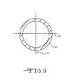
- FIG. 3is a sectional view of a body vessel within which embodiments of the invention can be used.
- FIG. 4is an end view of the distal end of the delivery system illustrated in FIG. 1 and FIG. 2 .
- FIG. 5is an end view of the distal end of a delivery system according to an alternate embodiment.
- FIG. 6is a partial sectional view of the distal end of a delivery system according to a second exemplary embodiment.
- FIG. 7is an enlarged view, partially broken away, of the proximal end of the delivery system illustrated in FIG. 6 .
- FIGS. 1 and 2illustrate a delivery system, generally indicated at 10 , according to a first exemplary embodiment.
- the delivery system 10includes an elongate tubular member 12 , such as a conventional sheath member used in delivery systems known in the art, having proximal 14 and distal 16 ends.
- the proximal end 14may include one or more connectors 18 , ports 20 , or other accessory components for use with the delivery system 10 .
- a lumen 22extends through the elongate tubular member 12 from the proximal end 14 to the distal end 16 .
- a dilator 24is disposed within the lumen 22 of the elongate tubular member 12 and defines a mounting region 26 on which an expandable intraluminal medical device 28 is disposed.
- the elongate tubular member 12is initially disposed over the mounting region 26 and the expandable intraluminal medical device 28 but can be retracted or otherwise manipulated in a manner that exposes the intraluminal medical device 28 for deployment at a point of treatment within a body vessel.
- the dilator 24is slidably disposed within the lumen 22 of the elongate tubular member 12 and defines a wireguide lumen 30 through which a conventional wireguide (not illustrated) can be disposed, allowing the dilator 24 , and the delivery system 10 , to be advanced over a wireguide that has been previously placed within a body vessel.
- the various types of delivery systemscan be constructed as embodiments of the invention, including over-the-wire, rapid exchange, short wire, intraductal exchange, and other delivery system types known in the art.
- the wireguide lumen 30extends along the entire length of the dilator 24 .
- the lumen 30extends along only a portion of the dilator 24 in a manner that facilitates rapid exchange of components, as is known in the art.
- the dilator 24includes a main body 32 and a head member 34 .
- the head member 34substantially comprises the distal end of the dilator 24 and includes the mounting region 26 on which the intraluminal medical device 28 is disposed.
- the main body 32 and the head member 34are rotatably connected at connection 36 .
- the connection 36enables the head member 34 to rotate circumferentially about a lengthwise axis of the head member substantially independent of any circumferential rotation of the main body 32 .
- the connection 36can comprise any suitable means for rotatably connecting two members capable of sharing substantially the same lengthwise axis.
- FIG. 2illustrates one exemplary structure for the connection 36 .
- the main body 32defines a projection 38 that is received by a socket 40 defined by the head member 34 .
- the projection 38 and socket 40advantageously fit together in a manner that permits rotation of the head member 34 relative to the main body 32 but doesn't permit axial disconnection of these elements.
- the connection 36advantageously includes a degree of play between the elements to facilitate navigation of the dilator 24 , and indeed the delivery system 10 , through a body vessel, such as through curved and other tortuous sections of the vessel.
- any particular embodiment of the inventionwill depend on various considerations, including the desired ease of rotation of the head member 34 , the desired trackability of rotation of the head member 34 with rotation of the main body 32 , the relative tortuosity of the body vessels within which the embodiment is intended to be used, and other considerations.
- the head membercan comprise a tubular member disposed circumferentially around the distal end of the dilator 24 in a manner that allows the head member to at least partially rotate about the distal end as described herein.
- the head memberis disposed around a portion of the dilator, and share a lengthwise axis.
- the mounting region 26is formed on the external surface of the head member and the intraluminal medical device is disposed on the mounting region 26 .
- a suitable connectionthat permits such rotation of the head member about the distal end of the dilator 24 can advantageously be used.
- a connectioncomprising a mating projection and socket, formed on the distal end of the dilator 24 , is considered suitable.
- the wireguide lumen 30 of the dilator 24extends through both the main body 32 and the head member 34 in a substantially continuous manner to facilitate advancement of the dilator 24 , and the delivery system 10 as a whole, over a previously placed wireguide according to conventional percutaneous techniques.
- the head member 34has a proximal portion 42 and a distal portion 44 .
- the proximal portion 42includes the structure of the head member 34 that participates in the connection 36 , such as socket 40 shown in FIG. 2 .
- the proximal portion 42also includes the mounting region 26 on which the intraluminal medical device 28 is disposed.
- the mounting region 26can simply be a portion of the surface of the proximal portion 42 or, alternatively, can comprise a recessed section 46 of the proximal portion 42 that is adapted to receive the intraluminal medical device 28 , as illustrated in FIG. 2 .
- the intraluminal medical device 28may be advantageous to secure the intraluminal medical device 28 to the mounting region 26 or other portion of the head member 34 using an appropriate means for securing one item to another.
- Any suitable structurecan be used for the means for securing, including projections that protrude into and create a friction fit with a cell or other suitable structure of the intraluminal medical device 28 , one or more adhesive connections, and frangible mechanical connections.
- the structure chosen for any particular embodimentshould be selected to not only provide a connection between the head member 34 and the intraluminal medical device 28 that permits coordinated rotation of the head member 34 and the intraluminal medical device 28 while the elongate tubular member 12 is disposed about the intraluminal medical device 28 , but also to be sufficiently fragile to enable the intraluminal medical device 28 to expand and disengage from the means for securing when the elongate tubular member 12 is retracted from a position about the mounting region 26 to effect deployment of the intraluminal medical device 28 .
- Exemplary structures and other suitable means for securingare described in commonly-owned U.S. Patent Application Publication No. 2006/0058865, entitled DELIVERY SYSTEM WITH CONTROLLED FRICTIONAL PROPERTIES, the entire contents of which are hereby incorporated by reference into this disclosure.
- the distal portion 44 of the head member 34includes an orienting section 48 for orienting the head member 34 as it is advanced through a portion of a body vessel.
- the orienting section 48includes a support member 50 and at least one orienting member 52 extending therefrom.
- the support member 50extends from the proximal portion 42 of the head member 34 and advantageously has an outer diameter less than the outer diameter of the mounting region 26 and/or the proximal portion 42 of the head member 34 .
- the orienting member 52advantageously comprises a elongate resilient member, such as a strand formed of wire, plastic or other suitable material.
- the orienting member(s) 52 in any given embodimentcan be formed from any suitable resilient material(s), including stainless steel or an elastic alloy, such as nitinol, to permit the orienting member to be collapsed and collected into a sheath.
- the orienting members 52may be coated with any suitable coating or other material, including lubricious and/or bioactive coatings.
- the orienting membersmay be removably or permanently attached to the support member 50 .
- the orienting member 52may be similar in construction to the elongate resilient members of an expandable basket as is known in the art.
- a description of exemplary expandable basket structuresis provided in U.S. Patent Application Publication No. 2004/0225322 filed by Garrison et al. for DELIVERY SYSTEMS AND METHODS FOR DEPLOYING EXPANDABLE INTRALUMINAL MEDICAL DEVICES, the entire disclosure of which is expressly incorporated into this disclosure by this reference.
- Expandable basket structuresare known in the retrieval art and are commonly used to remove an object, such as a stone or other undesirable object, from a body cavity. Expandable basket structures have not been used, however, to orient an intraluminal medical device within a body vessel during advancement through a portion of a body vessel as described herein.
- the orienting section 48includes two orienting members 52 , 54 arranged in an opposing relationship and extending outwardly from the support member 50 to define a major axis 56 of the distal portion 44 of the head member 34 .
- the orienting members 52 , 54seek the major axis of the body vessel, due to their expandable nature, as the distal portion 44 of the head member 34 is advanced through a portion of a body vessel.
- each of the orienting members 52 , 54are advantageously attached to the support member 50 with a proximal end 58 angularly offset from a distal end 60 .
- the proximal end 58is advantageously offset approximately 90 degrees from the distal end 60 .
- the proximal end 58 of any given orienting member 52 , 54may be offset from the corresponding distal end 60 by any suitable angle from between 0 and 360 degrees.
- the proximal ends 58may be longitudinally aligned with the distal ends 60 with the orienting members 52 , 54 extending along one side of the support member 50 or with the orienting members 52 , 54 having been rotated or spiraled about the support member 50 so long as a major axis 56 is formed for the distal portion 44 of the head member 34 .
- an ancillary devicethat includes orienting members in lieu of orienting members 52 , 54 that are attached to the head member 34 can be used in embodiments of the invention.
- an ancillary devicesuch as the wire-formed members that include spacing members described in U.S. Patent Application Publication No. 2004/0225322, the entire contents of which are hereby incorporated by reference into this disclosure, can be passed through the wireguide lumen 30 until the spacing members emerge from the head member 34 of the dilator 24 .
- the spacing members in this alternate embodimentcan be configured to sufficiently engage the head member 34 upon emerging therefrom such that the head member 34 rotates with the rotation of the spacing members, as described above relative to the previously described and illustrated embodiment.
- any suitable number of orienting memberscan be used and the number chosen for a specific delivery system according to an embodiment of the invention will depend on several considerations, including the nature and type of the body vessel in which the delivery system is intended to be used. It is expected that the inclusion of two, three, or four orienting members would provide desirable behavior of the delivery system in a body vessel, but any suitable number can be included. Furthermore, it is not necessary that each orienting member include the same or similar offset as the other orienting member(s) included in a particular delivery system, although it is expected that the inclusion of two or more orienting members that have substantially the same offset between their respective proximal and distal ends would produce desired behavior of the delivery system in a body vessel.
- FIG. 5illustrates the distal end of a delivery system according to an alternate embodiment.
- the delivery system according to this embodimentis similar to the embodiment described above and illustrated in FIG. 1 , FIG. 2 , and FIG. 4 , except as described below.
- the head member 134includes a first pair of orienting members 160 , 162 that are disposed substantially opposite one another and are sized and arranged to define a major axis 150 for the distal portion 144 of the head member 134 .
- the head member 134also includes a second pair of orienting members 170 , 172 that are disposed substantially opposite one another and are sized and arranged to define a minor axis 180 for the distal portion 144 of the head member 134 .
- FIG. 1illustrates the distal end of a delivery system according to an alternate embodiment.
- the delivery system according to this embodimentis similar to the embodiment described above and illustrated in FIG. 1 , FIG. 2 , and FIG. 4 , except as described below.
- the head member 134includes
- proximal end 156 of each orienting memberillustrates the proximal end 156 of each orienting member as offset by approximately 90 degrees from the corresponding distal end 158 ; however, the proximal ends 156 may be offset from the distal ends 158 at any suitable angle from between 0 and 360 degrees so long as the desired major axis 150 and minor axis 180 are formed for the distal portion 144 of the head member 134 .
- the intraluminal medical device 28is positioned on the mounting region 26 with the intraluminal device 28 aligned with the major axis 56 of the distal portion 44 of the head member 34 in such a manner that a desired portion, such as a functional mechanism of the intraluminal medical device 28 , is aligned with the major axis 56 .
- the intraluminal medical devicecomprises a valve device and it is desired to deploy the valve device in a manner that positions the valve orifice substantially across a major axis of a body vessel, the valve device is positioned on the mounting region 26 with the valve orifice substantially aligned with the major axis 56 of the distal portion 44 of the head member 34 , as defined by the appropriate orienting members 52 , 54 .
- the intraluminal medical device 28comprises a stent having a localized deposit of a bioactive agent and it is desired to deploy the stent in a manner that positions the bioactive agent adjacent a portion of the vessel wall that is on the major or minor axis of the body vessel, the stent is positioned on the mounting region 26 with the bioactive agent substantially aligned with the major 56 or minor 18 axis of the distal portion 44 of the head member 34 , as desired and as defined by the appropriate orienting members 52 , 54 .
- the head member 34may include suitable markings, such as registration markings, to aid in orienting the intraluminal device 28 on the mounting region 26 .
- the intraluminal medical device 28can comprise any suitable intraluminal medical device, including both self-expandable devices and those that require the input of an external force to effect expansion, such as balloon expandable intraluminal medical devices. If such devices are used, the dilator should be modified appropriately to accommodate the need for an external force to effect expansion, such as by including a balloon and an inflation lumen as is known in the art.
- intraluminal medical deviceused in a specific delivery system according to a particular embodiment of the invention will depend on several considerations, including the type of vessel in which the delivery system is being used and the nature of the clinical situation for which the delivery system has been selected.
- suitable types of intraluminal medical devicesinclude self-expandable stents, valve devices that include a self-expandable support frame, such as prosthetic valves for implantation in a vein (prosthetic venous valves) or in a heart vessel and/or chamber (prosthetic heart valves), self-expandable filters, distal protection devices, vessel occluders, and other self-expandable devices.
- Suitable self-expandable medical devices for use with delivery systems according to the inventioninclude those described in U.S. Pat. No. 6,200,336 to Pavcnik et al. for a MULTIPLE-SIDED INTRALUMINAL MEDICAL DEVICE; U.S. application for patent Ser. No. 10/642,372 of Pavcnik et al. for an IMPLANTABLE VASCULAR DEVICE, filed on Aug. 15, 2003; and U.S. application for patent Ser. No. 10/828,716 of Case, et al. for an ARTIFICIAL VALVE PROSTHESIS WITH IMPROVED FLOW DYNAMICS, filed on Apr. 21, 2004; the entire disclosures of which are hereby incorporated into this disclosure for the purpose of describing suitable self-expandable intraluminal medical devices for use with delivery systems described herein.
- the elongate tubular member 12Prior to deployment, the elongate tubular member 12 is circumferentially disposed around the dilator 24 , including at least a portion of the head member 34 so as to also be disposed circumferentially around the intraluminal medical device 28 .
- the elongate tubular member 12may be positioned about the orienting members 52 , 54 , if desired, until the head member 34 has been advanced through the body vessel to a position near a point of treatment. Once near the point of treatment, the elongate tubular member can be withdrawn to expose the orienting members 52 , 54 but not so far as to deploy or expose the intraluminal medical device.
- the dilator 24can be advanced such that the now expanded orienting members 52 , 54 , orient themselves in the body vessel and cause the head member 34 , including the intraluminal medical device 28 , to rotate circumferentially within the body vessel.
- the elongate tubular membermay be positioned circumferentially about the mounting region 26 while leaving the orienting members 52 , 54 exposed during the entire advancement process.
- the head member 34 , and the intraluminal medical device 28may experience rotational movement throughout all or a portion of the distance over which the dilator 24 is advanced. It is expected to be advantageous to expose the orientation member 52 , 54 only during a portion of the advancement process, such as over a short distance just prior to reaching the intended point of treatment in the body vessel.
- the delivery system 10is used to deliver and deploy an intraluminal device 28 in a body vessel, such as the vessel 90 illustrated in FIG. 3 . More specifically, the intraluminal device 28 is carried by the head member 34 . However, because of the rotational connection between the head member 34 and the main body 32 of the dilator 24 , the delivery system enables the intraluminal medical device 28 to be rotated to a desired orientation relative to the body vessel 30 prior to deployment of the intraluminal device 28 .
- Body vessels 90being formed of soft collagenous tissues, can exhibit an irregular or oval configuration, defined by a major axis 92 and a minor axis 94 , either constantly or dynamically, such as when the patient is in a supine or prone position.
- some intraluminal medical devicesmay not perform as desired if the device is not oriented in a desired manner relative to the major axis 92 of the body vessel 90 following deployment.
- some prosthetic valve devicesinclude a valve orifice that may not function as desired if the valve orifice is oriented with its axis grossly misaligned with the major axis of the body vessel. The leaflet or leaflets of a valve device mis-oriented in this manner may be obstructed or otherwise affected by such orientation.
- a userplaces a guidewire (not shown) in a body vessel 90 of a patient by navigating a distal end of the guidewire just beyond a point of treatment in the body vessel and leaving a proximal end of the guidewire outside of the patient.
- the useradvances the delivery system 10 over the previously placed guidewire by inserting the proximal end of the guidewire into the distal opening of the guidewire lumen 30 of the dilator 24 .
- the userthen advances the delivery system 10 along the path in the body vessel 90 established by the previously placed guidewire.
- the userhalts the advancement of the delivery system 10 .
- this procedureis conducted in conjunction with an imaging technique to verify positioning of the intraluminal device 28 at the desired point within the body vessel.
- the userretracts the elongate tubular member 12 while maintaining the position of the dilator 24 , or advances the dilator 24 while maintaining the position of the elongate tubular member 12 , to expose the orienting members 52 , 54 and effect their expansion.
- the delivery system 10is advanced to position the intraluminal device 28 at the desired point of treatment.
- the act of advancing the head member 34 and the orienting members 52 , 54causes the orienting members 52 , 54 to follow the contour of the body vessel 90 and cause the head member 34 , and thus the intraluminal medical device 28 , to rotate.
- the advancementcan be continued until the major axis 56 of the distal portion 44 of the head member 34 aligns with the major axis 92 of the body vessel 90 .
- the userfurther retracts the elongate tubular member 12 while maintaining the position of the head member 34 relative to the point of treatment, or advances the dilator 24 while maintaining the position of the elongate tubular member 12 .
- the intraluminal medical device 28is then expanded, either simply by the act of the removal of the constraining force provided by the elongate tubular member 12 or by the input of a required external force. Once the intraluminal medical device 28 expands along its entire axial length, it is freed from its position on the mounting region 26 of the head member 34 . The intraluminal medical device 28 is thus deployed in the body vessel 90 with the desired orientation relative to the body vessel 90 .
- the elongate tubular member 12 and the dilator 24are withdrawn from the body vessel 90 .
- the orienting members 52 , 54pass through the intraluminal medical device 28 .
- the elongate tubular member 12can be advanced over the head member 34 and the orienting members 52 , 54 to prevent contact between the orienting members 52 , 54 and/or the body vessel during subsequent retraction and withdrawal of the delivery system 10 from the body vessel 90 .
- FIGS. 6 and 7illustrate a delivery system 110 according to a second exemplary embodiment.
- This embodimenteliminates the optional rotatable head member in favor of a system of markings disposed on or otherwise associated with a functional wireguide and an elongate tubular member as described below.
- the delivery system 110includes an elongate tubular member 112 , such as a conventional sheath member used in delivery systems known in the art, having proximal 114 and distal ends 116 .
- a lumen 122extends through the elongate tubular member 112 from the proximal end 114 to the distal end 116 .
- a dilator 124is disposed within the lumen 122 of the elongate tubular member 112 and defines a mounting region 126 on which an expandable intraluminal medical device 128 is disposed.
- the elongate tubular member 112is initially disposed over the mounting region 126 and the expandable intraluminal medical device 128 but can be retracted in a manner that exposes the intraluminal medical device 128 for deployment at a point of treatment within a body vessel.
- the dilator 124is slidably disposed within the lumen 122 of the elongate tubular member 112 and defines a wireguide lumen 130 through which a wireguide 190 can be disposed, allowing the dilator 124 , and the delivery system 110 , to be advanced over a wireguide that has been previously placed within a body vessel.
- the wireguide lumen 130advantageously extends along the entire length of the dilator 124 .
- the wireguide 190includes at least one orienting member 192 extending therefrom.
- the at least one orienting member 192advantageously comprises a elongate resilient member, such as a strand formed of wire, plastic or other suitable material.
- the wireguide 190advantageously includes two or more orienting members 192 .
- the wireguide 190includes at least one longitudinal marker 194 or other suitable indicia that is aligned on the circumference of the wireguide 190 with one of the orienting members 192 .
- the longitudinal marker 194can extend along any suitable length of the wireguide 190 , including the entire length which is considered advantageous at least because it facilitates quality control checks during manufacturing and use, but should at least be disposed on a portion of the proximal end of the wireguide to facilitate alignment with the dilator 124 , as described below.
- the dilator 124includes at least one marker 196 or other suitable indicia.
- the expandable intraluminal medical device 128is advantageously disposed on the dilator 124 such that a particular component or feature of the expandable intraluminal medical device 128 is aligned with the marker 196 of the dilator, similar to the alignment between a portion of the medical device and the orienting members described above in relation to the first exemplary embodiment.
- the markers 194 , 196can be formed in or on their respective components, and can be formed of any suitable marker material, including conventional materials known in the art.
- Metallic markingssuch as bismuth-and gold-based markings, are considered suitable and advantageous at least because of their wide-spread use as markers in the delivery system art as well as their acceptable visualization properties.
- a skilled artisanwill be able to select an appropriate material based on various considerations, including desired visualization properties for the delivery system components using standard and newly-developed visualization techniques.
- a useradvances the wireguide 190 through a body vessel, allowing the orienting member(s) 192 to orient the wireguide within the body vessel as described above in relation to the head member of the first exemplary embodiment.
- the useradvances the delivery system 110 , including the dilator 124 and elongate tubular member 112 , along the path defined by the previously placed wireguide 190 .
- the intraluminal medical device 128Once the intraluminal medical device 128 has reached the desired point of treatment, the user rotates the dilator circumferentially about the wireguide 190 until the markers 194 , 196 are aligned.
- the rotationtransmits torque down the length of the dilator 124 and causes rotation of the expandable intraluminal medical device 128 at the point of treatment. Because of the alignment between a particular portion of the medical device 128 and the marker 196 , the intraluminal medical device 128 is positioned in the vessel in a desired configuration following the rotation to align the markers 194 , 196 . The elongate tubular member 112 can then be retracted to effect deployment of the expandable intraluminal medical device 128 at the point of treatment in the desired configuration.
Landscapes
- Health & Medical Sciences (AREA)
- Engineering & Computer Science (AREA)
- Biomedical Technology (AREA)
- Life Sciences & Earth Sciences (AREA)
- Animal Behavior & Ethology (AREA)
- Veterinary Medicine (AREA)
- Public Health (AREA)
- Heart & Thoracic Surgery (AREA)
- General Health & Medical Sciences (AREA)
- Transplantation (AREA)
- Vascular Medicine (AREA)
- Oral & Maxillofacial Surgery (AREA)
- Cardiology (AREA)
- Biophysics (AREA)
- Pulmonology (AREA)
- Anesthesiology (AREA)
- Hematology (AREA)
- Media Introduction/Drainage Providing Device (AREA)
- Surgical Instruments (AREA)
- Prostheses (AREA)
Abstract
Description
Claims (10)
Priority Applications (1)
| Application Number | Priority Date | Filing Date | Title |
|---|---|---|---|
| US11/800,292US8403977B2 (en) | 2006-05-04 | 2007-05-04 | Self-orienting delivery system |
Applications Claiming Priority (2)
| Application Number | Priority Date | Filing Date | Title |
|---|---|---|---|
| US74637806P | 2006-05-04 | 2006-05-04 | |
| US11/800,292US8403977B2 (en) | 2006-05-04 | 2007-05-04 | Self-orienting delivery system |
Publications (2)
| Publication Number | Publication Date |
|---|---|
| US20070260263A1 US20070260263A1 (en) | 2007-11-08 |
| US8403977B2true US8403977B2 (en) | 2013-03-26 |
Family
ID=38625859
Family Applications (1)
| Application Number | Title | Priority Date | Filing Date |
|---|---|---|---|
| US11/800,292Active2028-09-28US8403977B2 (en) | 2006-05-04 | 2007-05-04 | Self-orienting delivery system |
Country Status (3)
| Country | Link |
|---|---|
| US (1) | US8403977B2 (en) |
| EP (1) | EP2020965B1 (en) |
| WO (1) | WO2007130614A2 (en) |
Cited By (10)
| Publication number | Priority date | Publication date | Assignee | Title |
|---|---|---|---|---|
| US20110264199A1 (en)* | 2010-04-21 | 2011-10-27 | Medtronic, Inc. | Transcatheter Prosthetic Heart Valve Delivery System with Flush Report |
| US20150374492A1 (en)* | 2008-01-16 | 2015-12-31 | St. Jude Medical, Inc. | Delivery and retrieval systems for collapsible/expandable prosthetic heart valves |
| US9333077B2 (en) | 2013-03-12 | 2016-05-10 | Medtronic Vascular Galway Limited | Devices and methods for preparing a transcatheter heart valve system |
| US9549748B2 (en) | 2013-08-01 | 2017-01-24 | Cook Medical Technologies Llc | Methods of locating and treating tissue in a wall defining a bodily passage |
| US9833130B2 (en) | 2011-07-22 | 2017-12-05 | Cook Medical Technologies Llc | Irrigation devices adapted to be used with a light source for the identification and treatment of bodily passages |
| US9895055B2 (en) | 2013-02-28 | 2018-02-20 | Cook Medical Technologies Llc | Medical devices, systems, and methods for the visualization and treatment of bodily passages |
| US9937323B2 (en) | 2014-02-28 | 2018-04-10 | Cook Medical Technologies Llc | Deflectable catheters, systems, and methods for the visualization and treatment of bodily passages |
| US10195398B2 (en) | 2014-08-13 | 2019-02-05 | Cook Medical Technologies Llc | Tension member seal and securing mechanism for medical devices |
| US10940167B2 (en) | 2012-02-10 | 2021-03-09 | Cvdevices, Llc | Methods and uses of biological tissues for various stent and other medical applications |
| US11406495B2 (en) | 2013-02-11 | 2022-08-09 | Cook Medical Technologies Llc | Expandable support frame and medical device |
Families Citing this family (4)
| Publication number | Priority date | Publication date | Assignee | Title |
|---|---|---|---|---|
| US11298511B2 (en)* | 2006-11-21 | 2022-04-12 | Bridgepoint Medical, Inc. | Endovascular devices and methods for exploiting intramural space |
| DE102007006276A1 (en)* | 2007-01-31 | 2008-08-07 | Karl Storz Gmbh & Co. Kg | Medical instrument for cutting tissue |
| DE102017108521A1 (en)* | 2017-04-21 | 2018-10-25 | Biotronik Ag | Catheter device with rotatable distal tip |
| US11925556B2 (en)* | 2020-10-26 | 2024-03-12 | St. Jude Medical, Cardiology Division, Inc. | Passive alignment of commissures in prosthetic heart valve implantation |
Citations (51)
| Publication number | Priority date | Publication date | Assignee | Title |
|---|---|---|---|---|
| US2649092A (en) | 1949-10-26 | 1953-08-18 | American Cystoscope Makers Inc | Catheter |
| US3583391A (en) | 1968-11-21 | 1971-06-08 | American Hospital Supply Corp | Medical instrument with outrolling catheter |
| US4790812A (en) | 1985-11-15 | 1988-12-13 | Hawkins Jr Irvin F | Apparatus and method for removing a target object from a body passsageway |
| US5397311A (en) | 1992-09-09 | 1995-03-14 | Menlo Care, Inc. | Bloodless splittable introducer |
| US5509900A (en) | 1992-03-02 | 1996-04-23 | Kirkman; Thomas R. | Apparatus and method for retaining a catheter in a blood vessel in a fixed position |
| US5534007A (en) | 1995-05-18 | 1996-07-09 | Scimed Life Systems, Inc. | Stent deployment catheter with collapsible sheath |
| US5643171A (en) | 1993-05-04 | 1997-07-01 | Neocardia, Llc | Method and apparatus for uniform radiation treatment of vascular lumens |
| US5658301A (en) | 1995-04-26 | 1997-08-19 | Vascutech, Inc. | Self-centering valvulotome |
| US5718684A (en) | 1996-05-24 | 1998-02-17 | Gupta; Mukesh | Multi-lobed balloon catheter |
| US5769821A (en) | 1992-03-02 | 1998-06-23 | Quinton Instrument Company | Catheter tip retainer |
| US5779670A (en) | 1995-05-31 | 1998-07-14 | Bidwell; Robert E. | Catheter having lubricated sheathing |
| US5792114A (en) | 1996-12-16 | 1998-08-11 | Fiore; John M. | Introducer for sterile insertion of catheter |
| US5797952A (en)* | 1996-06-21 | 1998-08-25 | Localmed, Inc. | System and method for delivering helical stents |
| US5938582A (en) | 1997-09-26 | 1999-08-17 | Medtronic, Inc. | Radiation delivery centering catheter |
| US6007521A (en) | 1997-01-07 | 1999-12-28 | Bidwell; Robert E. | Drainage catheter system |
| US6117386A (en) | 1998-04-30 | 2000-09-12 | Medronic Inc. | Centering perfusion delivery catheter and method of manufacture |
| US6168617B1 (en) | 1999-06-14 | 2001-01-02 | Scimed Life Systems, Inc. | Stent delivery system |
| WO2001026726A1 (en) | 1999-10-07 | 2001-04-19 | Prodesco, Inc. | Intraluminal filter |
| US20010039450A1 (en)* | 1999-06-02 | 2001-11-08 | Dusan Pavcnik | Implantable vascular device |
| WO2001083017A1 (en) | 2000-05-02 | 2001-11-08 | Wilson-Cook Medical, Inc. | Introducer device for catheters o.t.l. with eversible sleeve |
| US20010044648A1 (en) | 1998-02-05 | 2001-11-22 | Medtronic, Inc. | Radially-expandable stent and delivery system |
| US6338735B1 (en) | 1991-07-16 | 2002-01-15 | John H. Stevens | Methods for removing embolic material in blood flowing through a patient's ascending aorta |
| US6383206B1 (en) | 1999-12-30 | 2002-05-07 | Advanced Cardiovascular Systems, Inc. | Embolic protection system and method including filtering elements |
| US20020068866A1 (en) | 2000-08-14 | 2002-06-06 | Zikorus Arthur W. | Method and apparatus for positioning a catheter relative to an anatomical junction |
| US6447530B1 (en) | 1996-11-27 | 2002-09-10 | Scimed Life Systems, Inc. | Atraumatic anchoring and disengagement mechanism for permanent implant device |
| US6450988B1 (en) | 1999-12-29 | 2002-09-17 | Advanced Cardiovascular Systems, Inc. | Centering catheter with improved perfusion |
| US6485500B1 (en)* | 2000-03-21 | 2002-11-26 | Advanced Cardiovascular Systems, Inc. | Emboli protection system |
| US6491662B1 (en) | 1997-09-23 | 2002-12-10 | Interventional Therapies Llc | Catheter with stand-off structure |
| US6500182B2 (en) | 1998-03-27 | 2002-12-31 | Cook Urological, Incorporated | Minimally-invasive medical retrieval device |
| US6508833B2 (en) | 1998-06-02 | 2003-01-21 | Cook Incorporated | Multiple-sided intraluminal medical device |
| US20030032977A1 (en) | 1997-11-07 | 2003-02-13 | Salviac Limited | Filter element with retractable guidewire tip |
| US20030050694A1 (en) | 2001-09-13 | 2003-03-13 | Jibin Yang | Methods and apparatuses for deploying minimally-invasive heart valves |
| CA2403030A1 (en) | 2001-09-14 | 2003-03-14 | Cordis Corporation | Recannalization device with integrated distal emboli protection |
| US20030055483A1 (en)* | 2001-08-23 | 2003-03-20 | Gumm Darrell C. | Rotating stent delivery system for side branch access and protection and method of using same |
| US6629987B1 (en) | 1999-07-30 | 2003-10-07 | C. R. Bard, Inc. | Catheter positioning systems |
| US6679860B2 (en) | 2001-06-19 | 2004-01-20 | Medtronic Ave, Inc. | Intraluminal therapy catheter with inflatable helical member and methods of use |
| US6692484B1 (en) | 1999-07-17 | 2004-02-17 | Wilson-Cook Medical Incorporated | Devices for extracting biliary or urinary stones |
| US6695858B1 (en) | 1998-02-10 | 2004-02-24 | Artemis Medical, Inc. | Medical device and methods for use |
| US20040087965A1 (en) | 2002-11-01 | 2004-05-06 | Marc-Alan Levine | Method and apparatus for caged stent delivery |
| WO2004082530A2 (en) | 2003-03-19 | 2004-09-30 | Cook Incorporated | Delivery systems for deploying expandable intraluminal medical devices |
| US20050125050A1 (en) | 2003-12-04 | 2005-06-09 | Wilson Cook Medical Incorporated | Biliary stent introducer system |
| US20050149096A1 (en) | 2003-12-23 | 2005-07-07 | Hilal Said S. | Catheter with conduit traversing tip |
| US6918929B2 (en)* | 2003-01-24 | 2005-07-19 | Medtronic Vascular, Inc. | Drug-polymer coated stent with pegylated styrenic block copolymers |
| US20050171592A1 (en)* | 2002-06-24 | 2005-08-04 | Majercak David C. | Spiral centering catheter |
| US20050228479A1 (en) | 2001-11-29 | 2005-10-13 | Cook Incorporated | Medical device delivery system |
| US20060058647A1 (en) | 1999-05-18 | 2006-03-16 | Mediguide Ltd. | Method and system for delivering a medical device to a selected position within a lumen |
| US20060058865A1 (en) | 2004-08-26 | 2006-03-16 | Case Brian C | Delivery system with controlled frictional properties |
| WO2006028821A1 (en) | 2004-09-01 | 2006-03-16 | Cook Incorporated | Delivery system which facilitates hydration of an intraluminal medical device |
| US20060135961A1 (en) | 2004-12-17 | 2006-06-22 | Biocardia, Inc. | Steerable guide catheters and methods for their use |
| US20070055326A1 (en) | 2005-07-21 | 2007-03-08 | Farley Brian E | Method of treating a hollow anatomical structure with a thermal catheter |
| US20070067021A1 (en) | 2005-09-21 | 2007-03-22 | Boston Scientific Scimed, Inc. | Venous valve, system, and method with sinus pocket |
- 2007
- 2007-05-04EPEP07794571.5Apatent/EP2020965B1/enactiveActive
- 2007-05-04WOPCT/US2007/010902patent/WO2007130614A2/enactiveApplication Filing
- 2007-05-04USUS11/800,292patent/US8403977B2/enactiveActive
Patent Citations (57)
| Publication number | Priority date | Publication date | Assignee | Title |
|---|---|---|---|---|
| US2649092A (en) | 1949-10-26 | 1953-08-18 | American Cystoscope Makers Inc | Catheter |
| US3583391A (en) | 1968-11-21 | 1971-06-08 | American Hospital Supply Corp | Medical instrument with outrolling catheter |
| US4790812A (en) | 1985-11-15 | 1988-12-13 | Hawkins Jr Irvin F | Apparatus and method for removing a target object from a body passsageway |
| US6338735B1 (en) | 1991-07-16 | 2002-01-15 | John H. Stevens | Methods for removing embolic material in blood flowing through a patient's ascending aorta |
| US6071263A (en) | 1992-03-02 | 2000-06-06 | Kirkman; Thomas R. | Apparatus and method for retaining a catheter in a blood vessel in a fixed position |
| US5509900A (en) | 1992-03-02 | 1996-04-23 | Kirkman; Thomas R. | Apparatus and method for retaining a catheter in a blood vessel in a fixed position |
| US5769821A (en) | 1992-03-02 | 1998-06-23 | Quinton Instrument Company | Catheter tip retainer |
| US6558349B1 (en) | 1992-03-02 | 2003-05-06 | Thomas R. Kirkman | Apparatus and method for retaining a catheter in a blood vessel in a fixed position |
| US5397311A (en) | 1992-09-09 | 1995-03-14 | Menlo Care, Inc. | Bloodless splittable introducer |
| US5643171A (en) | 1993-05-04 | 1997-07-01 | Neocardia, Llc | Method and apparatus for uniform radiation treatment of vascular lumens |
| US5658301A (en) | 1995-04-26 | 1997-08-19 | Vascutech, Inc. | Self-centering valvulotome |
| US5534007A (en) | 1995-05-18 | 1996-07-09 | Scimed Life Systems, Inc. | Stent deployment catheter with collapsible sheath |
| US5779670A (en) | 1995-05-31 | 1998-07-14 | Bidwell; Robert E. | Catheter having lubricated sheathing |
| US5718684A (en) | 1996-05-24 | 1998-02-17 | Gupta; Mukesh | Multi-lobed balloon catheter |
| US5797952A (en)* | 1996-06-21 | 1998-08-25 | Localmed, Inc. | System and method for delivering helical stents |
| US6447530B1 (en) | 1996-11-27 | 2002-09-10 | Scimed Life Systems, Inc. | Atraumatic anchoring and disengagement mechanism for permanent implant device |
| US5792114A (en) | 1996-12-16 | 1998-08-11 | Fiore; John M. | Introducer for sterile insertion of catheter |
| US6007521A (en) | 1997-01-07 | 1999-12-28 | Bidwell; Robert E. | Drainage catheter system |
| US6491662B1 (en) | 1997-09-23 | 2002-12-10 | Interventional Therapies Llc | Catheter with stand-off structure |
| US5938582A (en) | 1997-09-26 | 1999-08-17 | Medtronic, Inc. | Radiation delivery centering catheter |
| US20030032977A1 (en) | 1997-11-07 | 2003-02-13 | Salviac Limited | Filter element with retractable guidewire tip |
| US20010044648A1 (en) | 1998-02-05 | 2001-11-22 | Medtronic, Inc. | Radially-expandable stent and delivery system |
| US6695858B1 (en) | 1998-02-10 | 2004-02-24 | Artemis Medical, Inc. | Medical device and methods for use |
| US6500182B2 (en) | 1998-03-27 | 2002-12-31 | Cook Urological, Incorporated | Minimally-invasive medical retrieval device |
| US6117386A (en) | 1998-04-30 | 2000-09-12 | Medronic Inc. | Centering perfusion delivery catheter and method of manufacture |
| US6508833B2 (en) | 1998-06-02 | 2003-01-21 | Cook Incorporated | Multiple-sided intraluminal medical device |
| US20060058647A1 (en) | 1999-05-18 | 2006-03-16 | Mediguide Ltd. | Method and system for delivering a medical device to a selected position within a lumen |
| US20010039450A1 (en)* | 1999-06-02 | 2001-11-08 | Dusan Pavcnik | Implantable vascular device |
| US6168617B1 (en) | 1999-06-14 | 2001-01-02 | Scimed Life Systems, Inc. | Stent delivery system |
| US6692484B1 (en) | 1999-07-17 | 2004-02-17 | Wilson-Cook Medical Incorporated | Devices for extracting biliary or urinary stones |
| US6629987B1 (en) | 1999-07-30 | 2003-10-07 | C. R. Bard, Inc. | Catheter positioning systems |
| US20040087996A1 (en) | 1999-07-30 | 2004-05-06 | C. R. Bard, Inc. | Catheter positioning systems |
| WO2001026726A1 (en) | 1999-10-07 | 2001-04-19 | Prodesco, Inc. | Intraluminal filter |
| US6450988B1 (en) | 1999-12-29 | 2002-09-17 | Advanced Cardiovascular Systems, Inc. | Centering catheter with improved perfusion |
| US6383206B1 (en) | 1999-12-30 | 2002-05-07 | Advanced Cardiovascular Systems, Inc. | Embolic protection system and method including filtering elements |
| US6485500B1 (en)* | 2000-03-21 | 2002-11-26 | Advanced Cardiovascular Systems, Inc. | Emboli protection system |
| WO2001083017A1 (en) | 2000-05-02 | 2001-11-08 | Wilson-Cook Medical, Inc. | Introducer device for catheters o.t.l. with eversible sleeve |
| US20020068866A1 (en) | 2000-08-14 | 2002-06-06 | Zikorus Arthur W. | Method and apparatus for positioning a catheter relative to an anatomical junction |
| US6679860B2 (en) | 2001-06-19 | 2004-01-20 | Medtronic Ave, Inc. | Intraluminal therapy catheter with inflatable helical member and methods of use |
| US20030055483A1 (en)* | 2001-08-23 | 2003-03-20 | Gumm Darrell C. | Rotating stent delivery system for side branch access and protection and method of using same |
| US20030050694A1 (en) | 2001-09-13 | 2003-03-13 | Jibin Yang | Methods and apparatuses for deploying minimally-invasive heart valves |
| CA2403030A1 (en) | 2001-09-14 | 2003-03-14 | Cordis Corporation | Recannalization device with integrated distal emboli protection |
| US20050228479A1 (en) | 2001-11-29 | 2005-10-13 | Cook Incorporated | Medical device delivery system |
| US6932829B2 (en)* | 2002-06-24 | 2005-08-23 | Cordis Corporation | Centering catheter |
| US20050171592A1 (en)* | 2002-06-24 | 2005-08-04 | Majercak David C. | Spiral centering catheter |
| US20040087965A1 (en) | 2002-11-01 | 2004-05-06 | Marc-Alan Levine | Method and apparatus for caged stent delivery |
| US6918929B2 (en)* | 2003-01-24 | 2005-07-19 | Medtronic Vascular, Inc. | Drug-polymer coated stent with pegylated styrenic block copolymers |
| US20040225322A1 (en) | 2003-03-19 | 2004-11-11 | Garrison Michael L. | Delivery systems and methods for deploying expandable intraluminal medical devices |
| WO2004082530A2 (en) | 2003-03-19 | 2004-09-30 | Cook Incorporated | Delivery systems for deploying expandable intraluminal medical devices |
| US20050125050A1 (en) | 2003-12-04 | 2005-06-09 | Wilson Cook Medical Incorporated | Biliary stent introducer system |
| US20050149096A1 (en) | 2003-12-23 | 2005-07-07 | Hilal Said S. | Catheter with conduit traversing tip |
| US20060058865A1 (en) | 2004-08-26 | 2006-03-16 | Case Brian C | Delivery system with controlled frictional properties |
| WO2006028821A1 (en) | 2004-09-01 | 2006-03-16 | Cook Incorporated | Delivery system which facilitates hydration of an intraluminal medical device |
| US20060135961A1 (en) | 2004-12-17 | 2006-06-22 | Biocardia, Inc. | Steerable guide catheters and methods for their use |
| US20070055326A1 (en) | 2005-07-21 | 2007-03-08 | Farley Brian E | Method of treating a hollow anatomical structure with a thermal catheter |
| US20070055327A1 (en) | 2005-07-21 | 2007-03-08 | Esch Brady D | Therapeutic system with energy application device and programmed power delivery |
| US20070067021A1 (en) | 2005-09-21 | 2007-03-22 | Boston Scientific Scimed, Inc. | Venous valve, system, and method with sinus pocket |
Non-Patent Citations (1)
| Title |
|---|
| European Patent Office Communication for European patent application No. 07/794571.5 mailed Feb. 25, 2011. |
Cited By (18)
| Publication number | Priority date | Publication date | Assignee | Title |
|---|---|---|---|---|
| US20150374492A1 (en)* | 2008-01-16 | 2015-12-31 | St. Jude Medical, Inc. | Delivery and retrieval systems for collapsible/expandable prosthetic heart valves |
| US12350152B2 (en) | 2008-01-16 | 2025-07-08 | St. Juse Medical, LLC | Delivery and retrieval systems for collapsible/expandable prosthetic heart valves |
| US11452600B2 (en) | 2008-01-16 | 2022-09-27 | St. Jude Medical, Llc | Delivery and retrieval systems for collapsible/expandable prosthetic heart valves |
| US10258469B2 (en)* | 2008-01-16 | 2019-04-16 | St. Jude Medical, Llc | Delivery and retrieval systems for collapsible/expandable prosthetic heart valves |
| US20110264199A1 (en)* | 2010-04-21 | 2011-10-27 | Medtronic, Inc. | Transcatheter Prosthetic Heart Valve Delivery System with Flush Report |
| US8740976B2 (en)* | 2010-04-21 | 2014-06-03 | Medtronic, Inc. | Transcatheter prosthetic heart valve delivery system with flush report |
| US9980631B2 (en) | 2011-07-22 | 2018-05-29 | Cook Medical Technologies Llc | Irrigation devices adapted to be used with a light source for the identification and treatment of bodily passages |
| US9833130B2 (en) | 2011-07-22 | 2017-12-05 | Cook Medical Technologies Llc | Irrigation devices adapted to be used with a light source for the identification and treatment of bodily passages |
| US10940167B2 (en) | 2012-02-10 | 2021-03-09 | Cvdevices, Llc | Methods and uses of biological tissues for various stent and other medical applications |
| US11406495B2 (en) | 2013-02-11 | 2022-08-09 | Cook Medical Technologies Llc | Expandable support frame and medical device |
| US9895055B2 (en) | 2013-02-28 | 2018-02-20 | Cook Medical Technologies Llc | Medical devices, systems, and methods for the visualization and treatment of bodily passages |
| US10010411B2 (en) | 2013-03-12 | 2018-07-03 | Medtronic Vascular Galway | Devices and methods for preparing a transcatheter heart valve system |
| US9333077B2 (en) | 2013-03-12 | 2016-05-10 | Medtronic Vascular Galway Limited | Devices and methods for preparing a transcatheter heart valve system |
| US10136907B2 (en) | 2013-08-01 | 2018-11-27 | Cook Medical Technologies Llc | Methods of locating and treating tissue in a wall defining a bodily passage |
| US9549748B2 (en) | 2013-08-01 | 2017-01-24 | Cook Medical Technologies Llc | Methods of locating and treating tissue in a wall defining a bodily passage |
| US9937323B2 (en) | 2014-02-28 | 2018-04-10 | Cook Medical Technologies Llc | Deflectable catheters, systems, and methods for the visualization and treatment of bodily passages |
| US10814098B2 (en) | 2014-02-28 | 2020-10-27 | Cook Medical Technologies Llc | Deflectable catheters, systems, and methods for the visualization and treatment of bodily passages |
| US10195398B2 (en) | 2014-08-13 | 2019-02-05 | Cook Medical Technologies Llc | Tension member seal and securing mechanism for medical devices |
Also Published As
| Publication number | Publication date |
|---|---|
| EP2020965A2 (en) | 2009-02-11 |
| EP2020965B1 (en) | 2017-04-19 |
| WO2007130614A3 (en) | 2008-01-17 |
| WO2007130614A2 (en) | 2007-11-15 |
| US20070260263A1 (en) | 2007-11-08 |
Similar Documents
| Publication | Publication Date | Title |
|---|---|---|
| US8403977B2 (en) | Self-orienting delivery system | |
| JP6829692B2 (en) | Heart valve prosthesis delivery system and method for delivering the heart valve prosthesis through the introducer sheath | |
| US20200397578A1 (en) | Devices, systems and methods for accurate positioning of a prosthetic valve | |
| US10398548B2 (en) | Delivery system deflection mechanism | |
| US7846198B2 (en) | Vascular prosthesis and methods of use | |
| US6562064B1 (en) | Placement catheter assembly | |
| EP1894545B1 (en) | Multiple in vivo implant delivery device | |
| US6572648B1 (en) | Endoluminal prosthesis and tissue separation condition treatment method | |
| US7862608B2 (en) | Vascular prosthesis and methods of use | |
| US6468298B1 (en) | Gripping delivery system for self-expanding stents and method of using the same | |
| JP4922942B2 (en) | Filter sending system | |
| US7806923B2 (en) | Side branch stent having a proximal split ring | |
| WO2018144598A1 (en) | Heart valve prostheses including torque anchoring mechanisms and delivery devices for the heart valve prostheses | |
| JP2006513010A5 (en) | ||
| JP2010227579A (en) | Transseptal cannula device, coaxial balloon delivery device, and method of using the same | |
| EP2777643B1 (en) | Implant introducer with helical trigger wire | |
| JP7477245B2 (en) | Valve implants, delivery systems and methods | |
| JP2007500040A (en) | Bifurcated stent delivery system | |
| US9763813B2 (en) | Medical stent | |
| CN117377445A (en) | Stabilizing implant deployment system |
Legal Events
| Date | Code | Title | Description |
|---|---|---|---|
| AS | Assignment | Owner name:COOK INCORPORATED, INDIANA Free format text:ASSIGNMENT OF ASSIGNORS INTEREST;ASSIGNORS:CASE, BRIAN C.;PAUL, RAM H.;REEL/FRAME:019575/0448 Effective date:20070627 | |
| AS | Assignment | Owner name:COOK MEDICAL TECHNOLOGIES LLC, INDIANA Free format text:CONFIRMATION ASSIGNMENT;ASSIGNOR:COOK INCORPORATED;REEL/FRAME:026931/0951 Effective date:20110721 | |
| STCF | Information on status: patent grant | Free format text:PATENTED CASE | |
| FPAY | Fee payment | Year of fee payment:4 | |
| MAFP | Maintenance fee payment | Free format text:PAYMENT OF MAINTENANCE FEE, 8TH YEAR, LARGE ENTITY (ORIGINAL EVENT CODE: M1552); ENTITY STATUS OF PATENT OWNER: LARGE ENTITY Year of fee payment:8 | |
| AS | Assignment | Owner name:WILMINGTON TRUST, NATIONAL ASSOCIATION, AS COLLATERAL AGENT, DELAWARE Free format text:SECURITY INTEREST;ASSIGNOR:COOK MEDICAL TECHNOLOGIES LLC;REEL/FRAME:066700/0277 Effective date:20240227 | |
| MAFP | Maintenance fee payment | Free format text:PAYMENT OF MAINTENANCE FEE, 12TH YEAR, LARGE ENTITY (ORIGINAL EVENT CODE: M1553); ENTITY STATUS OF PATENT OWNER: LARGE ENTITY Year of fee payment:12 |