US8403969B2 - Anterior vertebral plate with quick lock screw - Google Patents
Anterior vertebral plate with quick lock screwDownload PDFInfo
- Publication number
- US8403969B2 US8403969B2US11/700,232US70023207AUS8403969B2US 8403969 B2US8403969 B2US 8403969B2US 70023207 AUS70023207 AUS 70023207AUS 8403969 B2US8403969 B2US 8403969B2
- Authority
- US
- United States
- Prior art keywords
- plate
- bone
- screw
- screw head
- thread
- Prior art date
- Legal status (The legal status is an assumption and is not a legal conclusion. Google has not performed a legal analysis and makes no representation as to the accuracy of the status listed.)
- Expired - Fee Related, expires
Links
- 238000000034methodMethods0.000claimsabstractdescription11
- 230000000087stabilizing effectEffects0.000claimsabstractdescription6
- 230000006641stabilisationEffects0.000claimsabstractdescription5
- 238000011105stabilizationMethods0.000claimsabstractdescription5
- 210000000988bone and boneAnatomy0.000claimsdescription59
- 238000003780insertionMethods0.000claimsdescription5
- 230000037431insertionEffects0.000claimsdescription5
- 238000001356surgical procedureMethods0.000claimsdescription4
- 230000000399orthopedic effectEffects0.000claimsdescription3
- 230000003993interactionEffects0.000claimsdescription2
- 230000007246mechanismEffects0.000abstractdescription4
- 238000013459approachMethods0.000description5
- 239000000463materialSubstances0.000description5
- 238000013461designMethods0.000description4
- 230000000694effectsEffects0.000description3
- 210000004872soft tissueAnatomy0.000description3
- 230000000295complement effectEffects0.000description2
- 239000002131composite materialSubstances0.000description2
- 230000008569processEffects0.000description2
- RTAQQCXQSZGOHL-UHFFFAOYSA-NTitaniumChemical compound[Ti]RTAQQCXQSZGOHL-UHFFFAOYSA-N0.000description1
- 230000032683agingEffects0.000description1
- 230000008901benefitEffects0.000description1
- 238000005266castingMethods0.000description1
- 239000000788chromium alloySubstances0.000description1
- 238000011161developmentMethods0.000description1
- 230000018109developmental processEffects0.000description1
- 201000010099diseaseDiseases0.000description1
- 208000037265diseases, disorders, signs and symptomsDiseases0.000description1
- 239000007943implantSubstances0.000description1
- 230000006872improvementEffects0.000description1
- 208000014674injuryDiseases0.000description1
- 238000003754machiningMethods0.000description1
- 239000007769metal materialSubstances0.000description1
- 238000012986modificationMethods0.000description1
- 230000004048modificationEffects0.000description1
- 238000000465mouldingMethods0.000description1
- 238000009740moulding (composite fabrication)Methods0.000description1
- 238000004806packaging method and processMethods0.000description1
- 239000004033plasticSubstances0.000description1
- 229920003023plasticPolymers0.000description1
- 239000010935stainless steelSubstances0.000description1
- 229910001220stainless steelInorganic materials0.000description1
- 239000010936titaniumSubstances0.000description1
- 229910052719titaniumInorganic materials0.000description1
- 230000007704transitionEffects0.000description1
- 230000008733traumaEffects0.000description1
Images


Classifications
- A—HUMAN NECESSITIES
- A61—MEDICAL OR VETERINARY SCIENCE; HYGIENE
- A61B—DIAGNOSIS; SURGERY; IDENTIFICATION
- A61B17/00—Surgical instruments, devices or methods
- A61B17/56—Surgical instruments or methods for treatment of bones or joints; Devices specially adapted therefor
- A61B17/58—Surgical instruments or methods for treatment of bones or joints; Devices specially adapted therefor for osteosynthesis, e.g. bone plates, screws or setting implements
- A61B17/68—Internal fixation devices, including fasteners and spinal fixators, even if a part thereof projects from the skin
- A61B17/70—Spinal positioners or stabilisers, e.g. stabilisers comprising fluid filler in an implant
- A61B17/7059—Cortical plates
- A—HUMAN NECESSITIES
- A61—MEDICAL OR VETERINARY SCIENCE; HYGIENE
- A61B—DIAGNOSIS; SURGERY; IDENTIFICATION
- A61B17/00—Surgical instruments, devices or methods
- A61B17/56—Surgical instruments or methods for treatment of bones or joints; Devices specially adapted therefor
- A61B17/58—Surgical instruments or methods for treatment of bones or joints; Devices specially adapted therefor for osteosynthesis, e.g. bone plates, screws or setting implements
- A61B17/68—Internal fixation devices, including fasteners and spinal fixators, even if a part thereof projects from the skin
- A61B17/80—Cortical plates, i.e. bone plates; Instruments for holding or positioning cortical plates, or for compressing bones attached to cortical plates
- A61B17/8033—Cortical plates, i.e. bone plates; Instruments for holding or positioning cortical plates, or for compressing bones attached to cortical plates having indirect contact with screw heads, or having contact with screw heads maintained with the aid of additional components, e.g. nuts, wedges or head covers
- A—HUMAN NECESSITIES
- A61—MEDICAL OR VETERINARY SCIENCE; HYGIENE
- A61B—DIAGNOSIS; SURGERY; IDENTIFICATION
- A61B17/00—Surgical instruments, devices or methods
- A61B17/56—Surgical instruments or methods for treatment of bones or joints; Devices specially adapted therefor
- A61B17/58—Surgical instruments or methods for treatment of bones or joints; Devices specially adapted therefor for osteosynthesis, e.g. bone plates, screws or setting implements
- A61B17/68—Internal fixation devices, including fasteners and spinal fixators, even if a part thereof projects from the skin
- A61B17/84—Fasteners therefor or fasteners being internal fixation devices
- A61B17/86—Pins or screws or threaded wires; nuts therefor
- A61B17/8625—Shanks, i.e. parts contacting bone tissue
- A61B17/8635—Tips of screws
Definitions
- the present inventionrelates to devices and methods for use in orthopedic spine surgery.
- the present inventionrelates to a system that provides a low profile anterior vertebral body plate and quick lock screws for the fixation and stabilization of the cervical spine, the quick lock screw in combination with the anterior vertebral plate providing a novel screw locking mechanism that requires no additional locking elements.
- the various plates, which are attached to the anterior vertebral bodies of the spinal column by bone screwshave some common features such as relatively planar body profiles that define multiple holes or slots through which the screws fit and are threaded into the bone.
- Various meanshave been used to prevent the screws from becoming loose or detached from their necessary secured or locked attachment to the vertebral plate.
- the conventionally used plates and screwsis the manner in which the screws are locked into place in the hole or slot of the plate after the screws have been secured to the bone.
- the screw headcontains a threaded hole configured to receive a set screw. After the screw has been driven into bone and the head is seated in the plate hole, the set screw is inserted into the receiving hole of the screw head.
- the set screwis tapered to cause the screw head to expand and frictionally engage the wall of the plate hole, thereby resisting forces which tend to cause the screw to back out. While such mechanisms have worked to some degree, the addition of a small additional part, the set screw, at the time of surgery presents the potential hazard of dropping the set screw into the surgical field or otherwise misapplying the set screw to the screw head, for example, cross threading.
- Another approachis to add a cover to the plate after the screws have been placed.
- Such a designundesirably adds steps to the surgical procedure, thickness or height to the overall construct, and is susceptible to misapplication.
- Yet another direction taken in this effort to provide plates with locking elementsis to provide dedicated overlying features, which are attached to the top side of the vertebral plate for the purpose of covering at least a portion of the screw head and thereby holding the screw in a seated and locked position.
- these platesare designed to provide a variety of screw covering features that are pre-attached to the plate, and which can be selectively slid or rotated into position once it has been inserted. In some devices, such covering plates cover multiple screw heads.
- the machine thread in the plate holedoes not allow various angular positions between the screw and the plate, as the threads must match up and engage when the screw head reaches the hole.
- one plateprovides a threaded ring in the plate hole, which is intended to allow the head to assume a variety of angular positions.
- an anterior cervical plate systemthat can maintain a relatively low profile, as found in the non-locking plates while providing the security of a locking plate system.
- a vertebral platethat does not have additional separate locking elements with the predictable problems of locking elements becoming disengaged from the plate and migrating away from the top side of the plate into the surrounding soft tissue.
- the present inventionmeets the above identified need by providing a low profile anterior vertebral body plate, which is secured to the underlying bone using novel quick lock screws.
- a low profile anterior vertebral body platewhich is secured to the underlying bone using novel quick lock screws having at least one integrally formed locking element that engages a corresponding lock receiving structure integrally formed in the plate so as to secure and lock the screw into a set position relative to the plate.
- a low profile anterior vertebral body platewhich is secured to the underlying bone using novel quick lock screws, each of the screws having a screw head with at least one integral locking thread circumferentially disposed around at least a portion of the side of the screw head, the locking thread being configured to engage a complimentary locking flange, which is inwardly directed from the upper portion of at least one section of the inside wall of the plate screw hole.
- a low profile anterior vertebral body platewhich is secured to the underlying bone using novel quick lock screws, each of the screws having a screw head with multiple independent locking threads disposed around the circumference of the side of the screw head, the locking threads being configured to respectively engage corresponding locking flanges, which are inwardly directed from the upper portion of the inside wall of the plate screw hole, the locking threads terminating at each end with a flange engagement edge.
- a low profile anterior vertebral body platewhich is secured to the underlying bone using novel quick lock screws, each of the screws having a screw head with at least one substantially flat pitch integral locking thread disposed around less than the full circumference of the side of the screw head, each of the at least one locking thread being configured to engage a complimentary locking flange, which is inwardly directed from the upper portion of at least one section of the inside wall of the plate screw hole.
- a novel bone screwcapable of locking to an anterior vertebral body plate, the screw having a screw head with at least one substantially flat pitch locking thread disposed around less than the full circumference of the side of the screw head, the locking threads being configured to be capable of engaging a complimentary shaped locking flange disposed on the inner wall of a bone plate screw hole.
- a novel bone screwcapable of locking to an anterior vertebral body plate, the screw having a screw head with multiple substantially flat pitch locking threads disposed around less than the full circumference of the side of the screw head, the screw head further having at least one loosening/removing tool engaging structure defined in the surface of the screw head.
- a novel low profile anterior vertebral body plate systemincluding a plate and quick lock screws, the interaction between the quick lock screws and plate providing a locking mechanism not requiring any additional locking elements.
- Also provided is a method of stabilizing spinal vertebraeincluding providing a low profile anterior vertebral body plate, which is securely attached to the underlying bone of adjacent vertebrae using novel quick lock screws so as to hold one attached vertebra in a fixed position relative to the adjacent attached vertebra.
- kitswhich includes at least one low profile anterior vertebral body plate and a corresponding set of novel quick lock screws, the kit not requiring any additional locking elements.
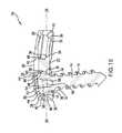
- FIGS. 1A-Erespectively show top, isometric, end, side, and enlarged cross-sectional views of the low profile anterior vertebral plate with two quick lock bone screws fully seated in the respective screw holes.
- FIGS. 2A-Drespectively show top, isometric, side and cross-sectional views of the low profile anterior vertebral plate.
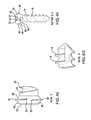
- FIGS. 3A-Erespectively show side, isometric, alternate side, threaded end, and screw head detail views of the quick lock screw.
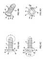
- FIGS. 4A-Grespectively show side, isometric, alternative side, threaded end, screw head detail view, side cross-sectional view and threaded end detail views of the quick lock screw.
- the systemas generally shown at 10 in FIGS. 1A-E , includes a low profile anterior vertebral body plate 12 that, when implanted in a patient, can be secured to the underlying bone using quick lock bone screws 14 as shown in FIGS. 1A-E , 3 A-E, and 4 A-G.
- the vertebral body plate 12as shown in FIGS. 1A-E , and 2 A-D can be provided as an elongated, low profile, plate structure that defines at least one and preferably multiple screw holes 16 , which are sized and configured to permit through passage for the threaded portion 18 of the bone screw 14 from the plate upper surface 20 to the plate lower surface 22 .
- the plate 12can be configured to be generally planar; however, the plate preferably will be formed to have arcuate upper and lower surfaces 20 , 22 , arcing along both the longitudinal axis 24 as well as the transverse axis 26 of the plate 12 . This arcing of the plate surface provides a better conformational fit to the anterior surface of the vertebrae to which the plate is to be attached.
- Each of the screw holes 16which are defined as through passages in the plate 12 , is configured at the upper portion 28 to be generally circular and sized to circumferentially surround the screw head 30 when the screw 14 is fully seated in the plate 12 .
- the lower portion 32 of the screw hole 16is configured to have an inwardly projecting edge 34 , which is formed by the generally inward slanting or rounded concave shaped surface 36 of the lower portion 32 of the plate wall defining the screw hole 16 .
- This inward slating or rounded concave shaped surface 36can have a complementary shape to that of the underside 38 of the screw head 30 .
- the inner most surface of the plate wall defining the upper portion 28 of the screw hole 16can include at least one inwardly projecting flange 40 , as shown in FIGS. 1 A,B and E.
- the at least one inwardly projecting flange 40forms a non-continuous circular shaped entry portal 42 for the screw hole 16 upper portion 28 .
- multiple inwardly projecting flanges 40can be provided, each of the flanges 40 being in an approximate alignment with the other flanges 40 .
- the edges terminal edges of each of the flangescan be provided with a taper 44 .
- the quick lock bone screw 14includes at least one locking thread 46 extending radially from at least a portion of the screw head 30 side wall 48 .
- the at least one locking thread 46can have a virtually flat pitch that rapidly transitions at each end of the thread to form an angled flange engagement/release terminus 50 .
- the engagement/release terminus 50 at each end of the locking thread 46is provided with an angle suitable to facilitate contact and engagement with one of the inwardly projecting flanges 40 provided on of the inner wall of the screw hole 16 when the screw 16 is turned in a clockwise direction.
- the other end of each of the locking threadsis provided with an angle suitable to facilitate release of the locking thread 46 from the flange 40 when the screw 16 is turned in a counterclockwise direction.
- the bone screw 14Upon insertion of an appropriate tightening/loosening tool and the application of clockwise directed torque, the bone screw 14 is drawn by the normal pitched threads of the threaded portion 18 of the screw 14 through the screw hole 16 and into the underlying bone material.
- the locking thread 46contacts the screw hole flange 40 and due to the angled thread terminus 40 interacting with the taper 44 of the flange 40 , the locking thread 46 is drawn beneath the flange 40 and into a locked position. Due to the initial contact of the locking thread 46 to the flange 40 , an increased tactile indication of increase rotational resistance can be felt during the locking of the screw 16 to the plate 12 .
- the resistanceis quickly overcome as the locking thread 46 is drawn below the flange 40 .
- Additional clockwise screw rotationcontinues to draw the screw into the bone and pulls the screw head 30 into a fully seated position in the screw hole 16 of the plate 12 .
- the additional rotation and resulting further advancement of the screw 14 into the underlying boneserves to pull the screw head 30 against the lower portion of the screw hole 32 and thus forces the plate 12 securely against the surface of the underlying bone.
- a counter-clockwise rotation of the screw 14can cause the upwardly angled terminus 50 of the locking thread 46 to engage the flange 40 and draw it into a position beneath the locking thread 46 thus releasing the screw head 30 from a locked position with the screw hole 16 .
- the thread engaging taper 44 of the flange 40can provide a more accommodating surface edge by which the flange 40 and the locking thread 46 of the screw 14 can become threadably engaged and interact during insertion, removal, and locking of the screw 14 to the plate 12 .
- the upper surface 52 of the screw head 30can define a tool receiving recess 54 , which is sized and configured to operationally engage a tightening/loosening/removal tool as needed.
- Tool gripping elements 56can be defined on the inner surface of the tool receiving recess 54 , the gripping elements 56 being of a complementary shape to the tool being used. Any of a variety of known or novel shapes for gripping elements 56 can be used so long as they are complimentary to the shape of the tool employed. As shown in the non-limiting exemplary embodiment of the bone screw 14 depicted in FIGS.
- the screw head 30can be provided with at least one loosening/removing tool engaging surface 58 , which can be defined in the tool receiving recess 54 .
- This removing tool engaging surface 58can be of any configuration and can be located within the tool receiving recess 54 or on any accessible surface of the screw head 30 so long as the engaging surface is configured and positioned to facilitate the screw head 30 being grasped and pulled in an upward direction away from the plate 12 during the simultaneous application of reverse torque to effect the screw 14 and plate 12 disengagement and removal process.
- a loosening/removing toolconfigured to engage the removing tool engaging surfaces 58 defined in the screw head 30 can facilitate the disengagement of the at least one locking thread 46 from the respective flange 40 in that the loosening/removing tool can engage the engaging surfaces 58 in the screw head 30 as the tool is simultaneously pulled away from the plate and turned in a counter-clockwise direction.
- the curvate underside 38 of the screw head 30 during screw insertionenables articulation of the screw head with the complimentary conformation of the lower portion 32 of the screw hole 16 .
- This capacity for the screw head 30 to articulate during the screw insertion process and then be locked into position relative to the plate 12enables the screw to be polyaxial in relationship to the plate as necessary.
- This polyaxial featureis a distinct advantage for a secure attachment to the underlying bone.
- the above described method of use of the system 10can be employed as a method of stabilizing or fixing injured or diseased vertebrae and if necessary, multiple devices or a device, which is elongated beyond the examples depicted herein, can be employed as necessary.
- the device as described hereincan be preferably used to attach to the anterior surface of cervical vertebrae and is configured to be capable of stabilizing cervical vertebrae, it is within the inventors' understanding that the plate can be configured and adapted to conform to any implantable surgical plate requirement to provide a low profile plate capable of securing and stabilizing any injured or diseased bone.
- the device 10can be manufactured as integral components by methods known in the art, to include, for example, molding, casting, forming or extruding, and machining processes.
- the componentscan be manufactured using materials having sufficient strength, resiliency and biocompatibility as is well known in the art for such devices.
- suitable materialscan include implant grade metallic materials, such as titanium, cobalt chromium alloys, stainless steel, or other suitable materials for this purpose. It is also conceivable that some components of the device can be made from plastics, composite materials, and the like.
- kitwhich includes at least one of the vertebral plate and quick lock screw systems disclosed herein.
- the kitcan also include additional orthopedic devices and instruments; such as for example, instruments for tightening or loosening the bone screws, spinal rods, hooks or links and any additional instruments or tools associated therewith.
- additional orthopedic devices and instrumentssuch as for example, instruments for tightening or loosening the bone screws, spinal rods, hooks or links and any additional instruments or tools associated therewith.
- Such a kitcan be provided with sterile packaging to facilitate opening and immediate use in an operating room.
Landscapes
- Health & Medical Sciences (AREA)
- Orthopedic Medicine & Surgery (AREA)
- Life Sciences & Earth Sciences (AREA)
- Neurology (AREA)
- Surgery (AREA)
- Heart & Thoracic Surgery (AREA)
- Engineering & Computer Science (AREA)
- Biomedical Technology (AREA)
- Nuclear Medicine, Radiotherapy & Molecular Imaging (AREA)
- Medical Informatics (AREA)
- Molecular Biology (AREA)
- Animal Behavior & Ethology (AREA)
- General Health & Medical Sciences (AREA)
- Public Health (AREA)
- Veterinary Medicine (AREA)
- Prostheses (AREA)
- Surgical Instruments (AREA)
Abstract
Description
Claims (13)
Priority Applications (1)
| Application Number | Priority Date | Filing Date | Title |
|---|---|---|---|
| US11/700,232US8403969B2 (en) | 2007-01-31 | 2007-01-31 | Anterior vertebral plate with quick lock screw |
Applications Claiming Priority (1)
| Application Number | Priority Date | Filing Date | Title |
|---|---|---|---|
| US11/700,232US8403969B2 (en) | 2007-01-31 | 2007-01-31 | Anterior vertebral plate with quick lock screw |
Publications (2)
| Publication Number | Publication Date |
|---|---|
| US20080234748A1 US20080234748A1 (en) | 2008-09-25 |
| US8403969B2true US8403969B2 (en) | 2013-03-26 |
Family
ID=39775518
Family Applications (1)
| Application Number | Title | Priority Date | Filing Date |
|---|---|---|---|
| US11/700,232Expired - Fee RelatedUS8403969B2 (en) | 2007-01-31 | 2007-01-31 | Anterior vertebral plate with quick lock screw |
Country Status (1)
| Country | Link |
|---|---|
| US (1) | US8403969B2 (en) |
Cited By (14)
| Publication number | Priority date | Publication date | Assignee | Title |
|---|---|---|---|---|
| US20130337409A1 (en)* | 2012-06-13 | 2013-12-19 | Maxon Motor Ag | Implant |
| US20160324557A1 (en)* | 2015-05-06 | 2016-11-10 | Warsaw Orthopedic, Inc. | Surgical implant system and method of use |
| US9504584B1 (en) | 2011-01-28 | 2016-11-29 | Nuvasive, Inc. | Spinal fusion implant and related methods |
| USD779065S1 (en) | 2014-10-08 | 2017-02-14 | Nuvasive, Inc. | Anterior cervical bone plate |
| US10537666B2 (en) | 2015-05-18 | 2020-01-21 | Stryker European Holdings I, Llc | Partially resorbable implants and methods |
| US10603182B2 (en) | 2015-01-14 | 2020-03-31 | Stryker European Holdings I, Llc | Spinal implant with fluid delivery capabilities |
| US10835388B2 (en) | 2017-09-20 | 2020-11-17 | Stryker European Operations Holdings Llc | Spinal implants |
| US20210062854A1 (en)* | 2017-09-07 | 2021-03-04 | Dieter Ramsauer | Grounding Countersunk Screw with Segment Cutting Edge |
| US11000386B2 (en) | 2015-01-14 | 2021-05-11 | Stryker European Holdings I, Llc | Spinal implant with porous and solid surfaces |
| US11026726B2 (en) | 2012-06-29 | 2021-06-08 | K2M, Inc. | Minimal-profile anterior cervical plate and cage apparatus and method of using same |
| USD949341S1 (en) | 2020-09-29 | 2022-04-19 | Trilliant Surgical Llc | Bone fixation plate |
| US11564721B2 (en) | 2019-09-27 | 2023-01-31 | Trilliant Surgical Llc | Variable angle locking construct for orthopedic applications |
| US11744619B2 (en) | 2018-04-06 | 2023-09-05 | K2M, Inc. | Faceted bone plate |
| US12403009B2 (en) | 2019-06-12 | 2025-09-02 | United States Government As Represented By The Department Of Veterans Affairs | Femoral head arthroplasty system |
Families Citing this family (18)
| Publication number | Priority date | Publication date | Assignee | Title |
|---|---|---|---|---|
| US8317843B2 (en)* | 2007-07-11 | 2012-11-27 | Perumala Corporation | Multi-axis connection and methods for internal spinal stabilizers |
| JP5662442B2 (en) | 2009-07-24 | 2015-01-28 | スパイナル・ユーエスエー・エルエルシー | Bone plate screw block system and method |
| KR20120082397A (en)* | 2009-07-24 | 2012-07-23 | 스파이널 유에스에이 엘엘씨 | Bone plate system and methods of using the same |
| AU2012271441B2 (en) | 2011-06-15 | 2017-02-02 | Smith & Nephew, Inc. | Variable angle locking implant |
| US8668723B2 (en) | 2011-07-19 | 2014-03-11 | Neurostructures, Inc. | Anterior cervical plate |
| KR101295443B1 (en) | 2011-10-27 | 2013-08-09 | (주)티디엠 | Connector for fracture |
| US9629664B2 (en) | 2014-01-20 | 2017-04-25 | Neurostructures, Inc. | Anterior cervical plate |
| US9486250B2 (en) | 2014-02-20 | 2016-11-08 | Mastros Innovations, LLC. | Lateral plate |
| US11197682B2 (en)* | 2015-08-27 | 2021-12-14 | Globus Medical, Inc. | Proximal humeral stabilization system |
| GB2557840B (en) | 2015-09-18 | 2021-07-21 | Smith & Nephew Inc | Bone plate |
| US10980641B2 (en) | 2017-05-04 | 2021-04-20 | Neurostructures, Inc. | Interbody spacer |
| US10512547B2 (en) | 2017-05-04 | 2019-12-24 | Neurostructures, Inc. | Interbody spacer |
| CN108186100A (en)* | 2018-02-09 | 2018-06-22 | 黄雁鸣 | The minimally invasive preceding road plate of Thoracolumbar disk |
| US11076892B2 (en) | 2018-08-03 | 2021-08-03 | Neurostructures, Inc. | Anterior cervical plate |
| US11071629B2 (en) | 2018-10-13 | 2021-07-27 | Neurostructures Inc. | Interbody spacer |
| US11382761B2 (en) | 2020-04-11 | 2022-07-12 | Neurostructures, Inc. | Expandable interbody spacer |
| US11304817B2 (en) | 2020-06-05 | 2022-04-19 | Neurostructures, Inc. | Expandable interbody spacer |
| US11717419B2 (en) | 2020-12-10 | 2023-08-08 | Neurostructures, Inc. | Expandable interbody spacer |
Citations (17)
| Publication number | Priority date | Publication date | Assignee | Title |
|---|---|---|---|---|
| US5954722A (en)* | 1997-07-29 | 1999-09-21 | Depuy Acromed, Inc. | Polyaxial locking plate |
| US6030389A (en)* | 1997-08-04 | 2000-02-29 | Spinal Concepts, Inc. | System and method for stabilizing the human spine with a bone plate |
| US6193721B1 (en)* | 1997-02-11 | 2001-02-27 | Gary K. Michelson | Multi-lock anterior cervical plating system |
| US6224602B1 (en)* | 1999-10-11 | 2001-05-01 | Interpore Cross International | Bone stabilization plate with a secured-locking mechanism for cervical fixation |
| US6322562B1 (en)* | 1998-12-19 | 2001-11-27 | Dietmar Wolter | Fixation system for bones |
| US20030153919A1 (en)* | 2002-02-12 | 2003-08-14 | Harris Peter M. | Self-locking bone screw and implant |
| US20030187442A1 (en)* | 2002-03-12 | 2003-10-02 | Marc Richelsoph | Bone plate and screw retaining mechanism |
| US6669700B1 (en)* | 1997-05-15 | 2003-12-30 | Sdgi Holdings, Inc. | Anterior cervical plating system |
| US6730091B1 (en)* | 1999-05-03 | 2004-05-04 | Medartis Ag | Blockable bone plate |
| US20050149026A1 (en)* | 2003-12-22 | 2005-07-07 | Life Spine | Static & dynamic cervical plates and cervical plate constructs |
| US20050192578A1 (en)* | 2004-02-26 | 2005-09-01 | Horst Steven P. | Bone plates with locking apertures |
| US7063701B2 (en)* | 1999-05-05 | 2006-06-20 | Sdgi Holdings, Inc. | Screws of cortical bone having a trailing end configured to cooperatively engage an implant |
| US20060235400A1 (en)* | 2003-08-26 | 2006-10-19 | Rolf Schneider | Bone plate |
| US20060276793A1 (en)* | 2005-05-26 | 2006-12-07 | Amedica Corporation | Bone fixation plate with self-locking screws |
| US7220263B2 (en)* | 2002-10-04 | 2007-05-22 | Seaspine, Inc. | Cervical plate/screw system for immobilizing vertebral bodies |
| US7322984B2 (en)* | 2005-01-06 | 2008-01-29 | Spinal, Llc | Spinal plate with internal screw locks |
| US7766948B1 (en)* | 2005-05-05 | 2010-08-03 | Ebi, Llc | Bone fixation assembly |
- 2007
- 2007-01-31USUS11/700,232patent/US8403969B2/ennot_activeExpired - Fee Related
Patent Citations (19)
| Publication number | Priority date | Publication date | Assignee | Title |
|---|---|---|---|---|
| US6193721B1 (en)* | 1997-02-11 | 2001-02-27 | Gary K. Michelson | Multi-lock anterior cervical plating system |
| US6669700B1 (en)* | 1997-05-15 | 2003-12-30 | Sdgi Holdings, Inc. | Anterior cervical plating system |
| US5954722A (en)* | 1997-07-29 | 1999-09-21 | Depuy Acromed, Inc. | Polyaxial locking plate |
| US6030389A (en)* | 1997-08-04 | 2000-02-29 | Spinal Concepts, Inc. | System and method for stabilizing the human spine with a bone plate |
| US6322562B1 (en)* | 1998-12-19 | 2001-11-27 | Dietmar Wolter | Fixation system for bones |
| US6730091B1 (en)* | 1999-05-03 | 2004-05-04 | Medartis Ag | Blockable bone plate |
| US7063701B2 (en)* | 1999-05-05 | 2006-06-20 | Sdgi Holdings, Inc. | Screws of cortical bone having a trailing end configured to cooperatively engage an implant |
| US6224602B1 (en)* | 1999-10-11 | 2001-05-01 | Interpore Cross International | Bone stabilization plate with a secured-locking mechanism for cervical fixation |
| US20030153919A1 (en)* | 2002-02-12 | 2003-08-14 | Harris Peter M. | Self-locking bone screw and implant |
| US7322983B2 (en)* | 2002-02-12 | 2008-01-29 | Ebi, L.P. | Self-locking bone screw and implant |
| US20030187442A1 (en)* | 2002-03-12 | 2003-10-02 | Marc Richelsoph | Bone plate and screw retaining mechanism |
| US7220263B2 (en)* | 2002-10-04 | 2007-05-22 | Seaspine, Inc. | Cervical plate/screw system for immobilizing vertebral bodies |
| US20060235400A1 (en)* | 2003-08-26 | 2006-10-19 | Rolf Schneider | Bone plate |
| US20050149026A1 (en)* | 2003-12-22 | 2005-07-07 | Life Spine | Static & dynamic cervical plates and cervical plate constructs |
| US7318825B2 (en)* | 2003-12-22 | 2008-01-15 | Life Spine Llc | Dynamic cervical plates and cervical plate constructs |
| US20050192578A1 (en)* | 2004-02-26 | 2005-09-01 | Horst Steven P. | Bone plates with locking apertures |
| US7322984B2 (en)* | 2005-01-06 | 2008-01-29 | Spinal, Llc | Spinal plate with internal screw locks |
| US7766948B1 (en)* | 2005-05-05 | 2010-08-03 | Ebi, Llc | Bone fixation assembly |
| US20060276793A1 (en)* | 2005-05-26 | 2006-12-07 | Amedica Corporation | Bone fixation plate with self-locking screws |
Cited By (23)
| Publication number | Priority date | Publication date | Assignee | Title |
|---|---|---|---|---|
| US9913730B1 (en) | 2011-01-28 | 2018-03-13 | Nuvasive, Inc. | Spinal fixation system and related methods |
| US9504584B1 (en) | 2011-01-28 | 2016-11-29 | Nuvasive, Inc. | Spinal fusion implant and related methods |
| US20130337409A1 (en)* | 2012-06-13 | 2013-12-19 | Maxon Motor Ag | Implant |
| US9597167B2 (en)* | 2012-06-13 | 2017-03-21 | Lakeview Innovation Ltd. | Implant |
| US11026726B2 (en) | 2012-06-29 | 2021-06-08 | K2M, Inc. | Minimal-profile anterior cervical plate and cage apparatus and method of using same |
| USD779065S1 (en) | 2014-10-08 | 2017-02-14 | Nuvasive, Inc. | Anterior cervical bone plate |
| USD798455S1 (en) | 2014-10-08 | 2017-09-26 | Nuvasive, Inc. | Anterior cervical bone plate |
| US10603182B2 (en) | 2015-01-14 | 2020-03-31 | Stryker European Holdings I, Llc | Spinal implant with fluid delivery capabilities |
| US12268613B2 (en) | 2015-01-14 | 2025-04-08 | Stryker European Operations Holdings Llc | Spinal implant with porous and solid surfaces |
| US11000386B2 (en) | 2015-01-14 | 2021-05-11 | Stryker European Holdings I, Llc | Spinal implant with porous and solid surfaces |
| US11266510B2 (en) | 2015-01-14 | 2022-03-08 | Stryker European Operations Holdings Llc | Spinal implant with fluid delivery capabilities |
| US20160324557A1 (en)* | 2015-05-06 | 2016-11-10 | Warsaw Orthopedic, Inc. | Surgical implant system and method of use |
| US10537666B2 (en) | 2015-05-18 | 2020-01-21 | Stryker European Holdings I, Llc | Partially resorbable implants and methods |
| US11623027B2 (en) | 2015-05-18 | 2023-04-11 | Stryker European Operations Holdings Llc | Partially resorbable implants and methods |
| US12263279B2 (en) | 2015-05-18 | 2025-04-01 | Stryker European Operations Holdings Llc | Partially resorbable implants and methods |
| US20210062854A1 (en)* | 2017-09-07 | 2021-03-04 | Dieter Ramsauer | Grounding Countersunk Screw with Segment Cutting Edge |
| US11622867B2 (en) | 2017-09-20 | 2023-04-11 | Stryker European Operations Holdings Llc | Spinal implants |
| US12133806B2 (en) | 2017-09-20 | 2024-11-05 | Stryker European Operations Holdings Llc | Spinal implants |
| US10835388B2 (en) | 2017-09-20 | 2020-11-17 | Stryker European Operations Holdings Llc | Spinal implants |
| US11744619B2 (en) | 2018-04-06 | 2023-09-05 | K2M, Inc. | Faceted bone plate |
| US12403009B2 (en) | 2019-06-12 | 2025-09-02 | United States Government As Represented By The Department Of Veterans Affairs | Femoral head arthroplasty system |
| US11564721B2 (en) | 2019-09-27 | 2023-01-31 | Trilliant Surgical Llc | Variable angle locking construct for orthopedic applications |
| USD949341S1 (en) | 2020-09-29 | 2022-04-19 | Trilliant Surgical Llc | Bone fixation plate |
Also Published As
| Publication number | Publication date |
|---|---|
| US20080234748A1 (en) | 2008-09-25 |
Similar Documents
| Publication | Publication Date | Title |
|---|---|---|
| US8403969B2 (en) | Anterior vertebral plate with quick lock screw | |
| US8834535B2 (en) | Anterior vertebral plate with closed thread screw | |
| US8920479B2 (en) | Anterior vertebral plate with spike fixation | |
| US8118847B2 (en) | Anterior vertebral plate with underside locking mechanism | |
| US8303633B2 (en) | Dynamic anterior vertebral plate | |
| US20080234750A1 (en) | Anterior vertebral plate with taper lock screw | |
| US10492836B2 (en) | Anterior cervical plate | |
| US10456181B2 (en) | Spinal plate assembly having locking mechanism | |
| US9629664B2 (en) | Anterior cervical plate | |
| US6689134B2 (en) | Longitudinal plate assembly having an adjustable length | |
| US8632575B2 (en) | Low profile fastening assembly | |
| US8834536B2 (en) | Cervical plate fixation system | |
| US8500784B2 (en) | Variable angle screw plate systems | |
| US20100094357A1 (en) | Semi-constrained screw and spinal plate assembly | |
| JP2010505539A (en) | Port structure for non-rigid bone plate | |
| US9848925B2 (en) | Plate/screw locking mechanism devices, systems and methods | |
| US20090030466A1 (en) | Anterior vertebral plate with suture lock | |
| US9451995B1 (en) | Anterior cervical plate with fixed angle caudal screws | |
| US11857224B2 (en) | Bone plate |
Legal Events
| Date | Code | Title | Description |
|---|---|---|---|
| AS | Assignment | Owner name:K2M, INC., VIRGINIA Free format text:ASSIGNMENT OF ASSIGNORS INTEREST;ASSIGNORS:WALLENSTEIN, TODD M.;HARRIS, PETER M.;REEL/FRAME:019177/0781 Effective date:20070312 | |
| AS | Assignment | Owner name:SILICON VALLEY BANK, CALIFORNIA Free format text:SECURITY AGREEMENT;ASSIGNOR:K2M, INC.;REEL/FRAME:023032/0109 Effective date:20090729 Owner name:SILICON VALLEY BANK,CALIFORNIA Free format text:SECURITY AGREEMENT;ASSIGNOR:K2M, INC.;REEL/FRAME:023032/0109 Effective date:20090729 | |
| AS | Assignment | Owner name:SILICON VALLEY BANK, MASSACHUSETTS Free format text:SECURITY INTEREST;ASSIGNORS:K2M, INC.;K2M HOLDING, INC.;K2M UK LIMITED;REEL/FRAME:029489/0327 Effective date:20121029 | |
| STCF | Information on status: patent grant | Free format text:PATENTED CASE | |
| AS | Assignment | Owner name:K2M, INC., VIRGINIA Free format text:TERMINATION;ASSIGNOR:SILICON VALLEY BANK;REEL/FRAME:030918/0426 Effective date:20121029 | |
| AS | Assignment | Owner name:SILICON VALLEY BANK, CALIFORNIA Free format text:FIRST AMENDMENT TO PATENT SECURITY AGREEMENT;ASSIGNORS:K2M, INC.;K2M UNLIMITED;K2M HOLDINGS, INC.;REEL/FRAME:034034/0097 Effective date:20141021 | |
| FEPP | Fee payment procedure | Free format text:PAT HOLDER NO LONGER CLAIMS SMALL ENTITY STATUS, ENTITY STATUS SET TO UNDISCOUNTED (ORIGINAL EVENT CODE: STOL); ENTITY STATUS OF PATENT OWNER: LARGE ENTITY | |
| AS | Assignment | Owner name:SILICON VALLEY BANK, AS ADMINISTRATIVE AGENT, CALIFORNIA Free format text:THIRD AMENDMENT TO PATENT SECURITY AGREEMENT;ASSIGNORS:K2M, INC.;K2M HOLDINGS, INC.;K2M UK LIMITED;REEL/FRAME:039627/0659 Effective date:20160808 Owner name:SILICON VALLEY BANK, AS ADMINISTRATIVE AGENT, CALI Free format text:THIRD AMENDMENT TO PATENT SECURITY AGREEMENT;ASSIGNORS:K2M, INC.;K2M HOLDINGS, INC.;K2M UK LIMITED;REEL/FRAME:039627/0659 Effective date:20160808 | |
| FPAY | Fee payment | Year of fee payment:4 | |
| AS | Assignment | Owner name:K2M HOLDINGS, INC., VIRGINIA Free format text:RELEASE BY SECURED PARTY;ASSIGNOR:SILICON VALLEY BANK;REEL/FRAME:047496/0001 Effective date:20181109 Owner name:K2M, INC., VIRGINIA Free format text:RELEASE BY SECURED PARTY;ASSIGNOR:SILICON VALLEY BANK;REEL/FRAME:047496/0001 Effective date:20181109 Owner name:K2M UK LIMITED, UNITED KINGDOM Free format text:RELEASE BY SECURED PARTY;ASSIGNOR:SILICON VALLEY BANK;REEL/FRAME:047496/0001 Effective date:20181109 | |
| FEPP | Fee payment procedure | Free format text:MAINTENANCE FEE REMINDER MAILED (ORIGINAL EVENT CODE: REM.); ENTITY STATUS OF PATENT OWNER: LARGE ENTITY | |
| LAPS | Lapse for failure to pay maintenance fees | Free format text:PATENT EXPIRED FOR FAILURE TO PAY MAINTENANCE FEES (ORIGINAL EVENT CODE: EXP.); ENTITY STATUS OF PATENT OWNER: LARGE ENTITY | |
| STCH | Information on status: patent discontinuation | Free format text:PATENT EXPIRED DUE TO NONPAYMENT OF MAINTENANCE FEES UNDER 37 CFR 1.362 | |
| FP | Lapsed due to failure to pay maintenance fee | Effective date:20210326 |