US8403940B2 - Tool to dissect or compress and measure a vertebral body segment - Google Patents
Tool to dissect or compress and measure a vertebral body segmentDownload PDFInfo
- Publication number
- US8403940B2 US8403940B2US12/033,337US3333708AUS8403940B2US 8403940 B2US8403940 B2US 8403940B2US 3333708 AUS3333708 AUS 3333708AUS 8403940 B2US8403940 B2US 8403940B2
- Authority
- US
- United States
- Prior art keywords
- indicia
- handle
- relative
- engagement means
- connecting element
- Prior art date
- Legal status (The legal status is an assumption and is not a legal conclusion. Google has not performed a legal analysis and makes no representation as to the accuracy of the status listed.)
- Active, expires
Links
Images


Classifications
- A—HUMAN NECESSITIES
- A61—MEDICAL OR VETERINARY SCIENCE; HYGIENE
- A61B—DIAGNOSIS; SURGERY; IDENTIFICATION
- A61B17/00—Surgical instruments, devices or methods
- A61B17/56—Surgical instruments or methods for treatment of bones or joints; Devices specially adapted therefor
- A61B17/58—Surgical instruments or methods for treatment of bones or joints; Devices specially adapted therefor for osteosynthesis, e.g. bone plates, screws or setting implements
- A61B17/68—Internal fixation devices, including fasteners and spinal fixators, even if a part thereof projects from the skin
- A61B17/70—Spinal positioners or stabilisers, e.g. stabilisers comprising fluid filler in an implant
- A61B17/7074—Tools specially adapted for spinal fixation operations other than for bone removal or filler handling
- A61B17/7076—Tools specially adapted for spinal fixation operations other than for bone removal or filler handling for driving, positioning or assembling spinal clamps or bone anchors specially adapted for spinal fixation
- A61B17/7077—Tools specially adapted for spinal fixation operations other than for bone removal or filler handling for driving, positioning or assembling spinal clamps or bone anchors specially adapted for spinal fixation for moving bone anchors attached to vertebrae, thereby displacing the vertebrae
- A61B17/708—Tools specially adapted for spinal fixation operations other than for bone removal or filler handling for driving, positioning or assembling spinal clamps or bone anchors specially adapted for spinal fixation for moving bone anchors attached to vertebrae, thereby displacing the vertebrae with tubular extensions coaxially mounted on the bone anchors
- A—HUMAN NECESSITIES
- A61—MEDICAL OR VETERINARY SCIENCE; HYGIENE
- A61B—DIAGNOSIS; SURGERY; IDENTIFICATION
- A61B90/00—Instruments, implements or accessories specially adapted for surgery or diagnosis and not covered by any of the groups A61B1/00 - A61B50/00, e.g. for luxation treatment or for protecting wound edges
- A61B90/06—Measuring instruments not otherwise provided for
- A61B2090/061—Measuring instruments not otherwise provided for for measuring dimensions, e.g. length
- A—HUMAN NECESSITIES
- A61—MEDICAL OR VETERINARY SCIENCE; HYGIENE
- A61B—DIAGNOSIS; SURGERY; IDENTIFICATION
- A61B90/00—Instruments, implements or accessories specially adapted for surgery or diagnosis and not covered by any of the groups A61B1/00 - A61B50/00, e.g. for luxation treatment or for protecting wound edges
- A61B90/06—Measuring instruments not otherwise provided for
- A61B2090/067—Measuring instruments not otherwise provided for for measuring angles
Definitions
- the technology of the present applicationrelates generally to spinal surgery, and more specifically to tools that distract, compress, and measure a spinal vertebral segment.
- a minimally invasive spinal fusion procedurefor example, is accomplished by threading pedicle screws to pedicles of adjacent vertebrae defining a spinal segment using screw extenders.
- a distraction deviceis attached to the screw extenders of a spinal segment the surgeon desires to distract.
- Distraction forceis applied.
- a measurement toolis inserted through the hollow tubes to measure the distance between the pedicles.
- the surgeondesires to compress the segment.
- the distraction toolis not usable to compress the segment, but rather a compression tool is used.
- a measurement toolis inserted through the screw extenders.
- the distance between pediclesis measured without any compression or distraction force to yield an approximate measurement of the distance between pedicles.
- the present inventionprovides tools to distract, compress, and measure a vertebral body segment.
- a tool for distracting and compressing a vertebral body segmentincludes a handle assembly and a locking mechanism operable between a first condition in which the first and second handle portions can translate and pivot relative to one another and a second condition in which the first and second handle portions are fixed translatably relative to one another and the first and second handle portions can pivot relative to one another.
- First and second gripsare responsive to movement toward one another to move first and second engagement means closer together
- second and third gripsare responsive to movement toward one another to move the first and second engagement means further apart.
- a tool for distracting and compressing a vertebral body segmentincludes a handle assembly selectively operable to move first and second engagement means toward and away from one another.
- the toolfurther includes a measuring device to simultaneously indicate the length of a connecting element for coupling the fasteners.
- a tool for determining the length of a connecting element needed to bridge between first and second fasteners mounted to first and second vertebral bodies of a vertebral body segmentincludes first and second engagement means mounted for translation and pivoting relative to one another.
- Indicia mounted relative to the first and second engagement meansare each defined by a locus of points corresponding to a particular connecting element length and each point corresponds to one of a plurality of relative translated and angular positions of the first and second engagement means for the particular connecting element length such that the indicia and pointer indicate the connecting element length for a plurality of combinations of relative translated and angular positions of the first and second engagement means.
- a method of coupling a first fastener engaged with a first vertebrae to a second fastener engaged with a second vertebraeincludes translating and pivoting first and second portions of a tool relative to one another to align the first and second portions with the first and second fasteners; coupling the first portion of the tool to the first fastener; coupling the second portion of the tool to the second fastener; locking the first and second portions to prevent relative translation between them while permitting relative pivoting between them; and pivoting the first and second portions to one of compress and distract the first and second vertebrae relative to one another.
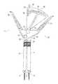
- FIG. 1is a front elevation view of a tool according to the present invention
- FIG. 2is a cross sectional view of the tool of FIG. 1 ;
- FIG. 3is a cross sectional view of the tool of FIG. 1 ;
- FIG. 4is a perspective view of a tool according to the present invention.
- FIG. 5is a perspective view of the tool of FIG. 4 ;
- FIG. 6is a cross sectional view of the tool of FIG. 4 ;
- FIG. 7is a front elevation view of the tool of FIG. 4 in use to measure for a rod between two pedicle screws in a spinal segment;
- FIG. 8is a front elevation view of a tool according to the present invention in use dot compress a spinal segment.
- tool 10includes a handle assembly 100 and a graduated measuring device 150 .
- the tool 10is shown coupled to screw extenders 12 , 14 that extend respective pedicle screws 16 , 18 , which would be coupled to vertebral bodies.
- the screw extenders 12 , 14are shown in the form of hollow tubes releasably engaged with the pedicle screws 16 , 18 .
- the screw extenders 12 , 14are generally known in the art and will not be further explained herein.
- FIGS. 2 and 3show cross sections of the handle assembly 100 .
- the handle assembly 100has a first handle portion 102 and a second handle portion 104 .
- the first handle portion 102has a protrusion 106 that couples to one of the screw extenders 12 .
- the second handle portion 104has a hollow channel 107 ( FIG. 2 ) to accept a pedicle screw driver 108 or the like.
- the driver 108extending through hollow channel 107 and extending through the screw extender 14 couples the second handle portion 104 to the screw extender 14 .
- the second handle portion 104may couple directly to the screw extension 14 such as by a protrusion 110 extending into the screw extension 14 .
- first handle portion 102 and second handle portion 104are slidably and pivotally coupled together by a releasable locking mechanism 112 .
- the locking mechanism 112has a threaded axle 114 connected to a first head 116 .
- the axle 114extends through a bore 118 in the first handle portion 102 , through a groove 120 in a tab 121 extending from the second handle portion 104 , and threadably engages a stop 122 .
- the axle 114extends completely through the first handle portion 102 and a second head 124 is mounted on the protruding end.
- the first and second heads 116 , 124are permanently fixed to the axle 114 such that rotating either of the first and second heads 116 , 124 causes axle 114 to rotate and the stop 122 to translate along the axle 114 between a first position in which the stop 122 is engaged with the tab 121 to prevent the second handle portion 104 from translating relative to the first handle portion 102 and a second position in which the stop 122 is disengaged from the tab 121 to allow the second handle portion 104 to translate relative to the first handle portion 102 .
- the stop 122may engage the tab 121 frictionally and/or positively.
- optional teeth 123may be formed on the abutting surfaces of the stop 122 and tab 121 so that they positively engage.
- the first handle portion 102 and second handle portion 104can move laterally with respect to one another as the axle 114 moves along the groove 120 and they can move pivotally with respect to each other about the axle 114 as a pivot point.
- the spacing of the handle portions 102 , 104can be adjusted to fit the screw extenders 12 , 14 which will be spaced and angled differently depending on the placement of the pedicle screws 16 , 18 , patient anatomy, and other variations in each surgical case.
- the first handle portion 102 and second handle portion 104are fixed laterally relative to one another but can still pivot with respect to each other about the axle 114 with the application of torque.
- the tool 10has three grips.
- a distract grip 126 and a compress grip 128mounted to the first handle portion 102 and a central grip 130 defined by the second handle portion 104 .
- the central grip 130is referred to as central because it resides between distract grip 126 and compress grip 128 and not because of general orientation (although it could be centered between the other grips).
- the distract grip 126 and compress grip 128are mounted to the first handle portion 102 in pivoting relationship about pivot pins 132 , 134 and are constrained to a limited pivot range by stop pins 136 , 138 engaged in slots 140 , 142 .
- the pivoting relationship of the grips 126 , 128permits a grip that is not being used (e.g. distract grip 126 in FIG. 2 ) to pivot away from the central grip 130 to provide increased clearance for a user's fingers. Likewise, the pivoting relationship permits a grip that is being used (e.g. compress grip 128 in FIG. 2 ) to pivot toward the central grip 130 to allow easy gripping of both the central grip 130 and the other grip being used.
- a surgeonwould grasp the distract grip 126 and the central grip 130 .
- the surgeonwould apply compressive force to move the distract grip 126 relatively towards the central grip 130 .
- the compressive forcecauses the first and second handle portions 102 , 104 to pivot relative to one another about the axle 114 and the screw extenders 12 , 14 to move apart to distract the vertebral segment.
- a surgeonwould grasp compress grip 128 and central grip 130 .
- the surgeonwould apply compressive force to move the compress grip 128 relatively towards central grip 130 .
- the compressive forcecauses the first and second handle portions 102 , 104 to pivot relative to one another about the axle 114 and the screw extenders 12 , 14 to move toward one another to compress the vertebral segment.
- a distance between the pedicle screws 16 , 18corresponds to the length of a rod 144 ( FIG. 1 ) needed to bridge between the pedicle screws 16 , 18 to fix them relative to one another and in a conventional manner to facilitate fusion.
- a pointer 146is mounted to the first handle portion 102 using a connection that may be for example, a press fit connection, friction fitting, snap lock connection, threaded connection or the like.
- the longitudinal axis 148 of the pointer 146is aligned with the axle 114 .
- a graduated measuring device 150 having a plurality of indicia 152 corresponding to various pedicle screw spacingsis mounted on the central grip 130 .
- the graduated measuring device 150fits the central grip 130 such that when it is placed on the central grip 130 , the tip 154 of the pointer resides about one of the plurality of indicia 152 indicating a distance corresponding to the length of rod 144 required to bridge between the pedicle screws 16 , 18 .
- the indicia 152are each defined by a locus of points in the form of a line or curve corresponding to a particular rod length. As the angle between the screw extenders increases, the graduated-measuring device 150 will tip relative to the pointer 146 and the pointer 146 will indicate increasing rod length.
- each indiciais defined by a locus of points corresponding to a particular rod length.
- Each pointcorresponds to one of a plurality of relative lateral and angular positions of the first and second handle portions 102 , 104 for the particular rod length such that the graduated measuring device 150 and pointer 146 will indicate the proper rod length for a plurality of combination of lateral spacing and angular orientation of the first and second handle portions 102 , 104 .
- the indiciamay be a series of discrete points.
- the indiciamay alternatively be in the form of continuous marks.
- the indiciamay be determined empirically by measuring and/or modeling the position of the parts for different discrete arrangements or they be calculated as a mathematical function.
- adjustable first and second handle portions 102 , 104 and a measurement device having individual indicia defined by a locus of points corresponding to a plurality of combinations of spacing and angular orientation of the handles portionsallows the instrument to be adjusted to fit a particular patient anatomy and screw placement while still indicating a correct rod length.
- the screw extenders 12 , 14can be rigidly coupled to the pedicle screws 16 , 18 for positive control of the screws 16 , 18 and the screw head orientation since the tool 10 can be adjusted to fit the angle of the screw extenders 12 , 14 .
- the measurement deviceis a simple angle indicator and the screws and screw extenders have to be adjusted to fit the inflexible configuration of the prior art measurement device.
- the tool 10may be removed to facilitate placing a rod to bridge the pedicle screws 16 , 18 .
- a set screwis tightened to couple the rod to one of the pedicle screws 16 and then the tool is again engaged with the screw extenders 12 , 14 .
- the driver 108is rotated to tighten a set screw to couple the rod to the other pedicle screw 18 and fix the spacing of the pedicle screws and thus the vertebral segment.
- FIGS. 4-7illustrate a measurement device 200 functionally similar to that of FIGS. 1-3 but able to be used independently of the first and second handle portions.
- This stand alone measurement device 200includes a body 204 with a first screw extension engagement portion in the form of a fixed post 206 mounted to the body 204 and a slot 208 in the body 204 .
- the pointer 210is fixed to a bushing 212 that rides in the slot in translating and pivoting arrangement to allow the pointer 210 to translate and pivot relative to the body 204 .
- the bushing 212receives a second screw extension engagement portion in the form of a mobile post 214 mounted to the bushing 212 for axial sliding within the bushing 212 .
- the bodyincludes indicia 216 each of which is defined by a locus of points corresponding to a particular rod length. Each point corresponds to one of a plurality of relative lateral and angular positions of the fixed and mobile posts 206 , 214 for a particular rod length.
- the measurement device 200may be coupled to the screw extenders 12 , 14 regardless of a particular patient anatomy and screw placement and still indicate a correct rod length.
- the sliding of the mobile post 214 axially relative to the bushing 212aids assembly to the screw extenders 12 , 14 by allowing the mobile post 214 to be withdrawn upwardly ( FIG. 6 ) so that the fixed post 206 may first be coupled to a screw extender 12 and the mobile post 214 then extended downwardly ( FIG. 4 ) to couple to the other screw extender 14 .
- FIGS. 4 and 5illustrate a cover 218 slidably engaged with the body 204 and movable from a first position ( FIG. 4 ) in which the pointer 210 and indicia 216 are uncovered and a second position ( FIG. 5 ) in which the pointer 210 and indicia 216 are covered and protected from impacts and abrasion that might occur during cleaning and storage.
- the body 204includes ball plungers 220 that engage the cover and selectively retain it in the first and second positions.
- the coveris omitted from FIGS. 6 and 7 for simplicity and clarity in illustrating the body 204 .
- FIG. 7illustrates the measurement device 200 in use to determine the rod length required to bridge two pedicle screws 16 , 18 .
- FIG. 8illustrates a tool 300 similar to that of FIG. 1 , but without the pointer 146 and graduated measuring device 150 , in use to compress or distract a spinal segment. It is contemplated and within the scope of the present invention that a tool can combine compression, distraction, and measurement as shown in the embodiment of FIG. 1 or that these functions can be separated into a measurement device as shown in FIG. 4 and a tool for compression and distraction as shown in FIG. 8 . Furthermore, in the embodiment of FIG. 1 , the pointer 146 and graduated measuring device 150 may be permanently assembled to the handle portions 102 , 104 or may be modular and selectively mountable to the first and second handle portions 102 , 104 .
Landscapes
- Health & Medical Sciences (AREA)
- Neurology (AREA)
- Orthopedic Medicine & Surgery (AREA)
- Life Sciences & Earth Sciences (AREA)
- Surgery (AREA)
- Heart & Thoracic Surgery (AREA)
- Engineering & Computer Science (AREA)
- Biomedical Technology (AREA)
- Nuclear Medicine, Radiotherapy & Molecular Imaging (AREA)
- Medical Informatics (AREA)
- Molecular Biology (AREA)
- Animal Behavior & Ethology (AREA)
- General Health & Medical Sciences (AREA)
- Public Health (AREA)
- Veterinary Medicine (AREA)
- Surgical Instruments (AREA)
- Prostheses (AREA)
Abstract
Description
Claims (18)
Priority Applications (1)
| Application Number | Priority Date | Filing Date | Title |
|---|---|---|---|
| US12/033,337US8403940B2 (en) | 2007-02-19 | 2008-02-19 | Tool to dissect or compress and measure a vertebral body segment |
Applications Claiming Priority (2)
| Application Number | Priority Date | Filing Date | Title |
|---|---|---|---|
| US89056107P | 2007-02-19 | 2007-02-19 | |
| US12/033,337US8403940B2 (en) | 2007-02-19 | 2008-02-19 | Tool to dissect or compress and measure a vertebral body segment |
Publications (2)
| Publication Number | Publication Date |
|---|---|
| US20080200919A1 US20080200919A1 (en) | 2008-08-21 |
| US8403940B2true US8403940B2 (en) | 2013-03-26 |
Family
ID=39707330
Family Applications (1)
| Application Number | Title | Priority Date | Filing Date |
|---|---|---|---|
| US12/033,337Active2031-10-02US8403940B2 (en) | 2007-02-19 | 2008-02-19 | Tool to dissect or compress and measure a vertebral body segment |
Country Status (1)
| Country | Link |
|---|---|
| US (1) | US8403940B2 (en) |
Cited By (6)
| Publication number | Priority date | Publication date | Assignee | Title |
|---|---|---|---|---|
| US9408716B1 (en) | 2013-12-06 | 2016-08-09 | Stryker European Holdings I, Llc | Percutaneous posterior spinal fusion implant construction and method |
| US9622795B2 (en) | 2013-12-13 | 2017-04-18 | Stryker European Holdings I, Llc | Tissue retraction and vertebral displacement devices, systems, and methods for posterior spinal fusion |
| US9744050B1 (en) | 2013-12-06 | 2017-08-29 | Stryker European Holdings I, Llc | Compression and distraction system for percutaneous posterior spinal fusion |
| US9907582B1 (en) | 2011-04-25 | 2018-03-06 | Nuvasive, Inc. | Minimally invasive spinal fixation system and related methods |
| US10159579B1 (en) | 2013-12-06 | 2018-12-25 | Stryker European Holdings I, Llc | Tubular instruments for percutaneous posterior spinal fusion systems and methods |
| US10194960B1 (en) | 2015-12-03 | 2019-02-05 | Nuvasive, Inc. | Spinal compression instrument and related methods |
Families Citing this family (1)
| Publication number | Priority date | Publication date | Assignee | Title |
|---|---|---|---|---|
| US9345547B2 (en)* | 2011-04-18 | 2016-05-24 | Warsaw Orthopedic, Inc. | Apparatus and method for sizing a connecting element for positioning along a bone structure |
Citations (10)
| Publication number | Priority date | Publication date | Assignee | Title |
|---|---|---|---|---|
| US4335715A (en)* | 1980-06-20 | 1982-06-22 | Kirkley William H | Osteotomy guide |
| US5891150A (en)* | 1996-12-04 | 1999-04-06 | Chan; Kwan-Ho | Apparatus and method for fixing a ligament in a bone tunnel |
| US20030060826A1 (en)* | 1999-10-20 | 2003-03-27 | Foley Kevin T. | Instruments and methods for stabilization of bony structures |
| US6620168B1 (en)* | 1998-10-13 | 2003-09-16 | Stryker Technologies Corporation | Methods and tools for tibial intermedullary revision surgery and associated tibial components |
| US20040138662A1 (en)* | 2002-10-30 | 2004-07-15 | Landry Michael E. | Spinal stabilization systems and methods |
| US20060036255A1 (en)* | 2004-08-13 | 2006-02-16 | Pond John D Jr | System and method for positioning a connecting member adjacent the spinal column in minimally invasive procedures |
| US7004947B2 (en)* | 2002-06-24 | 2006-02-28 | Endius Incorporated | Surgical instrument for moving vertebrae |
| US7160300B2 (en)* | 2004-02-27 | 2007-01-09 | Jackson Roger P | Orthopedic implant rod reduction tool set and method |
| US7794464B2 (en)* | 2006-02-09 | 2010-09-14 | Warsaw Orthopedic, Inc. | Spinal derotation instruments and methods |
| US7951175B2 (en)* | 2005-03-04 | 2011-05-31 | Depuy Spine, Inc. | Instruments and methods for manipulating a vertebra |
- 2008
- 2008-02-19USUS12/033,337patent/US8403940B2/enactiveActive
Patent Citations (10)
| Publication number | Priority date | Publication date | Assignee | Title |
|---|---|---|---|---|
| US4335715A (en)* | 1980-06-20 | 1982-06-22 | Kirkley William H | Osteotomy guide |
| US5891150A (en)* | 1996-12-04 | 1999-04-06 | Chan; Kwan-Ho | Apparatus and method for fixing a ligament in a bone tunnel |
| US6620168B1 (en)* | 1998-10-13 | 2003-09-16 | Stryker Technologies Corporation | Methods and tools for tibial intermedullary revision surgery and associated tibial components |
| US20030060826A1 (en)* | 1999-10-20 | 2003-03-27 | Foley Kevin T. | Instruments and methods for stabilization of bony structures |
| US7004947B2 (en)* | 2002-06-24 | 2006-02-28 | Endius Incorporated | Surgical instrument for moving vertebrae |
| US20040138662A1 (en)* | 2002-10-30 | 2004-07-15 | Landry Michael E. | Spinal stabilization systems and methods |
| US7160300B2 (en)* | 2004-02-27 | 2007-01-09 | Jackson Roger P | Orthopedic implant rod reduction tool set and method |
| US20060036255A1 (en)* | 2004-08-13 | 2006-02-16 | Pond John D Jr | System and method for positioning a connecting member adjacent the spinal column in minimally invasive procedures |
| US7951175B2 (en)* | 2005-03-04 | 2011-05-31 | Depuy Spine, Inc. | Instruments and methods for manipulating a vertebra |
| US7794464B2 (en)* | 2006-02-09 | 2010-09-14 | Warsaw Orthopedic, Inc. | Spinal derotation instruments and methods |
Cited By (14)
| Publication number | Priority date | Publication date | Assignee | Title |
|---|---|---|---|---|
| US11596453B2 (en) | 2011-04-25 | 2023-03-07 | Nuvasive, Inc. | Minimally invasive spinal fixation system |
| US10716600B1 (en) | 2011-04-25 | 2020-07-21 | Nuvasive, Inc. | Minimally invasive spinal fixation system |
| US12357350B2 (en) | 2011-04-25 | 2025-07-15 | Nuvasive, Inc. | Minimally invasive spinal fixation system and related methods |
| US9907582B1 (en) | 2011-04-25 | 2018-03-06 | Nuvasive, Inc. | Minimally invasive spinal fixation system and related methods |
| US12127949B1 (en) | 2013-12-06 | 2024-10-29 | Stryker European Operations Holdings Llc | Percutaneous posterior spinal fusion implant construction and method |
| US9408716B1 (en) | 2013-12-06 | 2016-08-09 | Stryker European Holdings I, Llc | Percutaneous posterior spinal fusion implant construction and method |
| US10159579B1 (en) | 2013-12-06 | 2018-12-25 | Stryker European Holdings I, Llc | Tubular instruments for percutaneous posterior spinal fusion systems and methods |
| US9744050B1 (en) | 2013-12-06 | 2017-08-29 | Stryker European Holdings I, Llc | Compression and distraction system for percutaneous posterior spinal fusion |
| US10507046B2 (en) | 2013-12-13 | 2019-12-17 | Stryker European Holdings I, Llc | Tissue retraction and vertebral displacement devices, systems, and methods for posterior spinal fusion |
| US9622795B2 (en) | 2013-12-13 | 2017-04-18 | Stryker European Holdings I, Llc | Tissue retraction and vertebral displacement devices, systems, and methods for posterior spinal fusion |
| US11622793B2 (en) | 2013-12-13 | 2023-04-11 | Stryker European Operations Holdings Llc | Tissue retraction and vertebral displacement devices, systems, and methods for posterior spinal fusion |
| US10194960B1 (en) | 2015-12-03 | 2019-02-05 | Nuvasive, Inc. | Spinal compression instrument and related methods |
| US11006983B2 (en) | 2015-12-03 | 2021-05-18 | Nuvasive, Inc. | Spinal compression instrument and related methods |
| US12070252B2 (en) | 2015-12-03 | 2024-08-27 | Nuvasive, Inc. | Spinal compression instrument and related methods |
Also Published As
| Publication number | Publication date |
|---|---|
| US20080200919A1 (en) | 2008-08-21 |
Similar Documents
| Publication | Publication Date | Title |
|---|---|---|
| US8403940B2 (en) | Tool to dissect or compress and measure a vertebral body segment | |
| JP7522470B2 (en) | Surgical Connectors and Instruments | |
| US10441325B2 (en) | Minimally invasive fixation system | |
| US9833267B2 (en) | Surgical instrument with integrated compression and distraction mechanisms | |
| EP1916952B1 (en) | External fixation system | |
| US10098666B2 (en) | Minimally invasive spinal fixation system including vertebral alignment features | |
| US11471198B2 (en) | Implant driver | |
| US7666189B2 (en) | Less invasive surgical system and methods | |
| US9211149B2 (en) | Surgical apparatus | |
| US7749233B2 (en) | Sleeve assembly for spinal stabilization system and methods of use | |
| US7909830B2 (en) | Methods of spinal fixation and instrumentation | |
| US8834485B2 (en) | Measuring instrument for sizing an elongate stabilization element | |
| US8377065B2 (en) | Surgical instrument for fixing a clamp to a bone fixation device | |
| US8617165B2 (en) | Rod reducing instrument and methods of use thereof | |
| EP3047811B1 (en) | Rod reducer | |
| US10357314B2 (en) | Instrumentation and method for repair of a bone fracture | |
| JP6863986B2 (en) | Medical equipment and medical equipment | |
| US12390210B2 (en) | Modular length adjustable tubular retractor and a tube breaker | |
| CN212234663U (en) | Low lumbosacral vertebral anterior angled screw placement device | |
| KR20160137990A (en) | Spinal compressor and distractor | |
| US11712269B2 (en) | Adjustable, modular instrument and method for spinal manipulation | |
| US20250186096A1 (en) | Surgical systems and methods |
Legal Events
| Date | Code | Title | Description |
|---|---|---|---|
| AS | Assignment | Owner name:LANX, INC., COLORADO Free format text:CHANGE OF NAME;ASSIGNOR:LANX MEDICAL, INC.;REEL/FRAME:020690/0871 Effective date:20071228 Owner name:LANX, INC.,COLORADO Free format text:CHANGE OF NAME;ASSIGNOR:LANX MEDICAL, INC.;REEL/FRAME:020690/0871 Effective date:20071228 | |
| AS | Assignment | Owner name:LANX, INC., COLORADO Free format text:ASSIGNMENT OF ASSIGNORS INTEREST;ASSIGNORS:PARKER, JARED;CORIN, JAMES;BURKHOLDER, ALAN;REEL/FRAME:020772/0982 Effective date:20080311 | |
| STCF | Information on status: patent grant | Free format text:PATENTED CASE | |
| FEPP | Fee payment procedure | Free format text:PAT HOLDER NO LONGER CLAIMS SMALL ENTITY STATUS, ENTITY STATUS SET TO UNDISCOUNTED (ORIGINAL EVENT CODE: STOL); ENTITY STATUS OF PATENT OWNER: LARGE ENTITY | |
| AS | Assignment | Owner name:BANK OF AMERICA, N.A., AS ADMINISTRATIVE AGENT, NORTH CAROLINA Free format text:SECURITY AGREEMENT;ASSIGNOR:LANX, INC.;REEL/FRAME:032086/0664 Effective date:20140113 Owner name:BANK OF AMERICA, N.A., AS ADMINISTRATIVE AGENT, NO Free format text:SECURITY AGREEMENT;ASSIGNOR:LANX, INC.;REEL/FRAME:032086/0664 Effective date:20140113 | |
| AS | Assignment | Owner name:LANX, INC., COLORADO Free format text:RELEASE OF SECURITY INTEREST IN PATENTS RECORDED AT REEL 032086/ FRAME 0664;ASSIGNOR:BANK OF AMERICA, N.A., AS ADMINISTRATIVE AGENT;REEL/FRAME:037155/0041 Effective date:20150624 | |
| AS | Assignment | Owner name:ZIMMER BIOMET SPINE, INC., COLORADO Free format text:CHANGE OF NAME;ASSIGNOR:LANX, INC.;REEL/FRAME:037761/0231 Effective date:20150730 | |
| AS | Assignment | Owner name:ZIMMER BIOMET SPINE, INC., COLORADO Free format text:CORRECTIVE ASSIGNMENT TO CORRECT THE REMOVE APPL. NO. 14/828,714 PREVIOUSLY RECORDED AT REEL: 037761 FRAME: 0231. ASSIGNOR(S) HEREBY CONFIRMS THE CHANGE OF NAME;ASSIGNOR:LANX, INC.;REEL/FRAME:038951/0064 Effective date:20150730 | |
| FPAY | Fee payment | Year of fee payment:4 | |
| MAFP | Maintenance fee payment | Free format text:PAYMENT OF MAINTENANCE FEE, 8TH YEAR, LARGE ENTITY (ORIGINAL EVENT CODE: M1552); ENTITY STATUS OF PATENT OWNER: LARGE ENTITY Year of fee payment:8 | |
| AS | Assignment | Owner name:JPMORGAN CHASE BANK, N.A., AS ADMINISTRATIVE AGENT, NEW YORK Free format text:SECURITY INTEREST;ASSIGNORS:BIOMET 3I, LLC;EBI, LLC;ZIMMER BIOMET SPINE, INC.;AND OTHERS;REEL/FRAME:059293/0213 Effective date:20220228 | |
| AS | Assignment | Owner name:CERBERUS BUSINESS FINANCE AGENCY, LLC, NEW YORK Free format text:GRANT OF A SECURITY INTEREST -- PATENTS;ASSIGNORS:ZIMMER BIOMET SPINE, LLC;EBI, LLC;REEL/FRAME:066970/0806 Effective date:20240401 | |
| AS | Assignment | Owner name:ZIMMER BIOMET SPINE, LLC (F/K/A ZIMMER BIOMET SPINE, INC.), COLORADO Free format text:RELEASE BY SECURED PARTY;ASSIGNOR:JPMORGAN CHASE BANK, N.A.;REEL/FRAME:066973/0833 Effective date:20240401 Owner name:EBI, LLC, NEW JERSEY Free format text:RELEASE BY SECURED PARTY;ASSIGNOR:JPMORGAN CHASE BANK, N.A.;REEL/FRAME:066973/0833 Effective date:20240401 | |
| MAFP | Maintenance fee payment | Free format text:PAYMENT OF MAINTENANCE FEE, 12TH YEAR, LARGE ENTITY (ORIGINAL EVENT CODE: M1553); ENTITY STATUS OF PATENT OWNER: LARGE ENTITY Year of fee payment:12 | |
| AS | Assignment | Owner name:ZIMMER BIOMET SPINE, LLC, COLORADO Free format text:CHANGE OF NAME;ASSIGNOR:ZIMMER BIOMET SPINE, INC.;REEL/FRAME:069772/0121 Effective date:20240220 Owner name:HIGHRIDGE MEDICAL, LLC, COLORADO Free format text:CHANGE OF NAME;ASSIGNOR:ZIMMER BIOMET SPINE, LLC;REEL/FRAME:069772/0248 Effective date:20240405 |