US8403902B2 - Reduced-pressure medical systems and methods employing a moisture processing device - Google Patents
Reduced-pressure medical systems and methods employing a moisture processing deviceDownload PDFInfo
- Publication number
- US8403902B2 US8403902B2US13/108,753US201113108753AUS8403902B2US 8403902 B2US8403902 B2US 8403902B2US 201113108753 AUS201113108753 AUS 201113108753AUS 8403902 B2US8403902 B2US 8403902B2
- Authority
- US
- United States
- Prior art keywords
- reduced
- vapor
- liquid
- pressure
- processing device
- Prior art date
- Legal status (The legal status is an assumption and is not a legal conclusion. Google has not performed a legal analysis and makes no representation as to the accuracy of the status listed.)
- Expired - Fee Related, expires
Links
Images

Classifications
- A—HUMAN NECESSITIES
- A61—MEDICAL OR VETERINARY SCIENCE; HYGIENE
- A61M—DEVICES FOR INTRODUCING MEDIA INTO, OR ONTO, THE BODY; DEVICES FOR TRANSDUCING BODY MEDIA OR FOR TAKING MEDIA FROM THE BODY; DEVICES FOR PRODUCING OR ENDING SLEEP OR STUPOR
- A61M1/00—Suction or pumping devices for medical purposes; Devices for carrying-off, for treatment of, or for carrying-over, body-liquids; Drainage systems
- A61M1/80—Suction pumps
- A61M1/82—Membrane pumps, e.g. bulbs
- A—HUMAN NECESSITIES
- A61—MEDICAL OR VETERINARY SCIENCE; HYGIENE
- A61M—DEVICES FOR INTRODUCING MEDIA INTO, OR ONTO, THE BODY; DEVICES FOR TRANSDUCING BODY MEDIA OR FOR TAKING MEDIA FROM THE BODY; DEVICES FOR PRODUCING OR ENDING SLEEP OR STUPOR
- A61M1/00—Suction or pumping devices for medical purposes; Devices for carrying-off, for treatment of, or for carrying-over, body-liquids; Drainage systems
- A61M1/90—Negative pressure wound therapy devices, i.e. devices for applying suction to a wound to promote healing, e.g. including a vacuum dressing
- A61M1/91—Suction aspects of the dressing
- B—PERFORMING OPERATIONS; TRANSPORTING
- B01—PHYSICAL OR CHEMICAL PROCESSES OR APPARATUS IN GENERAL
- B01D—SEPARATION
- B01D53/00—Separation of gases or vapours; Recovering vapours of volatile solvents from gases; Chemical or biological purification of waste gases, e.g. engine exhaust gases, smoke, fumes, flue gases, aerosols
- B01D53/26—Drying gases or vapours
- B01D53/265—Drying gases or vapours by refrigeration (condensation)
- B—PERFORMING OPERATIONS; TRANSPORTING
- B01—PHYSICAL OR CHEMICAL PROCESSES OR APPARATUS IN GENERAL
- B01D—SEPARATION
- B01D53/00—Separation of gases or vapours; Recovering vapours of volatile solvents from gases; Chemical or biological purification of waste gases, e.g. engine exhaust gases, smoke, fumes, flue gases, aerosols
- B01D53/26—Drying gases or vapours
- B01D53/268—Drying gases or vapours by diffusion
- B—PERFORMING OPERATIONS; TRANSPORTING
- B01—PHYSICAL OR CHEMICAL PROCESSES OR APPARATUS IN GENERAL
- B01D—SEPARATION
- B01D61/00—Processes of separation using semi-permeable membranes, e.g. dialysis, osmosis or ultrafiltration; Apparatus, accessories or auxiliary operations specially adapted therefor
- B01D61/36—Pervaporation; Membrane distillation; Liquid permeation
- B01D61/362—Pervaporation
- A—HUMAN NECESSITIES
- A61—MEDICAL OR VETERINARY SCIENCE; HYGIENE
- A61M—DEVICES FOR INTRODUCING MEDIA INTO, OR ONTO, THE BODY; DEVICES FOR TRANSDUCING BODY MEDIA OR FOR TAKING MEDIA FROM THE BODY; DEVICES FOR PRODUCING OR ENDING SLEEP OR STUPOR
- A61M1/00—Suction or pumping devices for medical purposes; Devices for carrying-off, for treatment of, or for carrying-over, body-liquids; Drainage systems
- A61M1/70—Gravity drainage systems
- A—HUMAN NECESSITIES
- A61—MEDICAL OR VETERINARY SCIENCE; HYGIENE
- A61M—DEVICES FOR INTRODUCING MEDIA INTO, OR ONTO, THE BODY; DEVICES FOR TRANSDUCING BODY MEDIA OR FOR TAKING MEDIA FROM THE BODY; DEVICES FOR PRODUCING OR ENDING SLEEP OR STUPOR
- A61M1/00—Suction or pumping devices for medical purposes; Devices for carrying-off, for treatment of, or for carrying-over, body-liquids; Drainage systems
- A61M1/71—Suction drainage systems
- A—HUMAN NECESSITIES
- A61—MEDICAL OR VETERINARY SCIENCE; HYGIENE
- A61M—DEVICES FOR INTRODUCING MEDIA INTO, OR ONTO, THE BODY; DEVICES FOR TRANSDUCING BODY MEDIA OR FOR TAKING MEDIA FROM THE BODY; DEVICES FOR PRODUCING OR ENDING SLEEP OR STUPOR
- A61M2205/00—General characteristics of the apparatus
- A61M2205/11—General characteristics of the apparatus with means for preventing cross-contamination when used for multiple patients
- B—PERFORMING OPERATIONS; TRANSPORTING
- B01—PHYSICAL OR CHEMICAL PROCESSES OR APPARATUS IN GENERAL
- B01D—SEPARATION
- B01D53/00—Separation of gases or vapours; Recovering vapours of volatile solvents from gases; Chemical or biological purification of waste gases, e.g. engine exhaust gases, smoke, fumes, flue gases, aerosols
- B01D53/22—Separation of gases or vapours; Recovering vapours of volatile solvents from gases; Chemical or biological purification of waste gases, e.g. engine exhaust gases, smoke, fumes, flue gases, aerosols by diffusion
- B01D2053/221—Devices
- B—PERFORMING OPERATIONS; TRANSPORTING
- B01—PHYSICAL OR CHEMICAL PROCESSES OR APPARATUS IN GENERAL
- B01D—SEPARATION
- B01D2257/00—Components to be removed
- B01D2257/80—Water
- B—PERFORMING OPERATIONS; TRANSPORTING
- B01—PHYSICAL OR CHEMICAL PROCESSES OR APPARATUS IN GENERAL
- B01D—SEPARATION
- B01D2258/00—Sources of waste gases
- B01D2258/06—Polluted air
- B—PERFORMING OPERATIONS; TRANSPORTING
- B01—PHYSICAL OR CHEMICAL PROCESSES OR APPARATUS IN GENERAL
- B01D—SEPARATION
- B01D2259/00—Type of treatment
- B01D2259/45—Gas separation or purification devices adapted for specific applications
- B01D2259/4533—Gas separation or purification devices adapted for specific applications for medical purposes
- Y—GENERAL TAGGING OF NEW TECHNOLOGICAL DEVELOPMENTS; GENERAL TAGGING OF CROSS-SECTIONAL TECHNOLOGIES SPANNING OVER SEVERAL SECTIONS OF THE IPC; TECHNICAL SUBJECTS COVERED BY FORMER USPC CROSS-REFERENCE ART COLLECTIONS [XRACs] AND DIGESTS
- Y10—TECHNICAL SUBJECTS COVERED BY FORMER USPC
- Y10T—TECHNICAL SUBJECTS COVERED BY FORMER US CLASSIFICATION
- Y10T137/00—Fluid handling
- Y10T137/2931—Diverse fluid containing pressure systems
- Y10T137/3109—Liquid filling by evacuating container
- Y—GENERAL TAGGING OF NEW TECHNOLOGICAL DEVELOPMENTS; GENERAL TAGGING OF CROSS-SECTIONAL TECHNOLOGIES SPANNING OVER SEVERAL SECTIONS OF THE IPC; TECHNICAL SUBJECTS COVERED BY FORMER USPC CROSS-REFERENCE ART COLLECTIONS [XRACs] AND DIGESTS
- Y10—TECHNICAL SUBJECTS COVERED BY FORMER USPC
- Y10T—TECHNICAL SUBJECTS COVERED BY FORMER US CLASSIFICATION
- Y10T29/00—Metal working
- Y10T29/49—Method of mechanical manufacture
- Y10T29/49826—Assembling or joining
Definitions
- the present disclosurerelates generally to reduced-pressure medical treatment systems and, more particularly, but not by way of limitation, to reduced-pressure systems, devices, and methods employing a moisture processing device.
- reduced pressureis applied to tissue through a porous pad or other manifold device.
- the porous padcontains cells or pores that are capable of distributing reduced pressure to the tissue and channeling fluids that are drawn from the tissue. In more general applications, reduced pressure may be used to remove other fluids from a patient.
- a system for removing fluids from a patient using reduced pressureincludes a liquid receptor for receiving fluids from the patient, a canister fluidly coupled to the liquid receptor for receiving the fluids from the patient, a reduced-pressure delivery conduit, a reduced-pressure source fluidly coupled by the reduced-pressure delivery conduit to the canister, and a moisture processing device fluidly coupled to the reduced-pressure delivery conduit.
- the moisture processing deviceincludes a housing having an inlet and an outlet and forming an expanded volume to condense water from air entering the inlet and includes a first liquid-impermeable, vapor-permeable membrane forming at least a portion of the housing.
- the first liquid-impermeable, vapor-permeable membraneallows vapor in the expanded volume to egress the expanded volume.
- the systemmay also include a first hydrophobic filter fluidly coupled to the reduced-pressure delivery conduit.
- a method for removing fluids from a patient using reduced pressureincludes removing fluids from the patient with reduced pressure, delivering the fluids to a canister, and delivering reduced pressure to the canister through a reduced-pressure delivery conduit from a reduced-pressure source, whereby a fluid flow is created in the reduced-pressure delivery conduit.
- the methodfurther includes removing moisture from the fluid flow.
- the step of removing moistureincludes receiving the fluid flow, lowering the temperature of the fluid flow in a moisture processing device to condense water from the fluid flow to produce a drier fluid flow, and exposing the condensed water to a liquid-impermeable, vapor-permeable membrane to allow evaporated water to egress the moisture processing device.
- the methodmay also include exposing the drier fluid flow to a first hydrophobic filter.
- a method of manufacturing a system for removing fluids from a patient with reduced pressureincludes forming a liquid receptor, fluidly coupling a canister to the fluid receptor for receiving the fluids from the patient, providing a reduced-pressure delivery conduit, fluidly coupling a reduced pressure source via the reduced-pressure delivery conduit to the canister, and fluidly coupling a moisture processing device to the reduced-pressure delivery conduit.
- the moisture processing deviceincludes a housing having an inlet, an outlet, and an expanded volume to condense water from air entering the inlet.
- the moisture processing devicefurther includes a first liquid-impermeable, vapor-permeable membrane that forms at least a portion of the housing. The first liquid-impermeable, vapor-permeable membrane allows vapor in the expanded volume to egress the expanded volume.
- the methodmay further comprise fluidly coupling a first hydrophobic filter to the reduced-pressure delivery conduit.
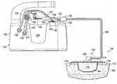
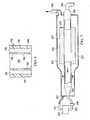
- FIG. 1is schematic diagram, with a portion shown in cross section, of a system for removing fluids from a patient with reduced pressure and including an illustrative, non-limiting embodiment of a moisture processing device;
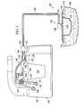
- FIG. 2is a schematic, perspective, partially-exploded view of an illustrative, non-limiting embodiment of the moisture processing device of FIG. 1 ;
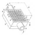
- FIG. 3is a schematic, perspective view of a portion of the moisture processing device of FIG. 2 shown with a portion in cross section taken along 3 - 3 in FIG. 2 ;
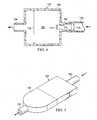
- FIG. 4is a schematic cross section of another illustrative, non-limiting embodiment of a moisture process unit
- FIG. 5is a schematic, perspective view of another illustrative, non-limiting embodiment of a moisture process unit
- FIG. 6is a schematic cross section of a portion of an illustrative, non-limiting embodiment of a moisture processing unit.
- FIG. 7is a schematic cross section of an alternative illustrative, non-limiting embodiment of a moisture process device.
- tissue site 104may be the bodily tissue of any human, animal, or other organism, including bone tissue, adipose tissue, muscle tissue, dermal tissue, vascular tissue, epithelial tissue, connective tissue, cartilage, tendons, ligaments, or any other tissue.
- the tissue site 104may be within a body cavity, such as an abdominal cavity.
- the treatment by the system 100may include removing fluids, such as ascites or exudates, delivering of reduced pressure, or providing a protective barrier. Unless otherwise indicated, as used throughout this document, “or” does not require mutual exclusivity.
- a liquid receptor 107receives fluids from the patient 105 and delivers the fluids to a conduit 106 .
- the liquid receptor 107may be any device or subsystem for receiving fluids from the patient 105 .
- the liquid receptor 107may include a suction device or reduced-pressure dressing or other means involving reduced pressure.
- the liquid receptor 107includes a reduced-pressure interface 108 that is fluidly coupled to a manifold 110 and covered by a sealing member 114 .
- the manifold 110is placed proximate to the tissue site 104 and receives fluids from the tissue site 104 .
- Reduced pressureis delivered through the conduit 106 to the reduced-pressure interface 108 .
- the reduced-pressure interface 108delivers the reduced pressure to the manifold 110 that is adjacent the tissue site 104 and thereby may receive fluids.
- the tissue site 104is shown as a wound, or damaged area of tissue, that involves epidermis 112 and other tissue layers.
- a fluid sealis formed over the patient's epidermis 112 by the sealing member 114 and an attachment device 116 , such as an adhesive on a patient-facing side 118 of the sealing member 114 .
- the fluid sealinvolves a seal adequate to maintain reduced pressure at a desired site given the particular reduced-pressure source or subsystem involved.
- the conduit 106may be a dual-lumen conduit wherein one lumen delivers reduced pressure and transports removed fluids, such as exudates or ascites.
- the other lumen of conduit 106may provide a pressure-sensing lumen to allow the pressure at the tissue site 104 to be measured or otherwise determined by a remote measuring device.
- the conduit 106may contain additional lumens, but in this example is a dual-lumen design.
- the conduit 106may also be a single lumen.
- the conduit 106is fluidly coupled to, or in fluid communication with, an interface member 120 .
- the interface member 120fluidly couples the first lumen of the conduit 106 to a second reduced-pressure delivery conduit 122 and fluidly couples the second lumen of the conduit 106 to a first pressure-sensing conduit 124 .
- the second reduced-pressure delivery conduit 122is coupled to at least a portion of a medical canister connector, for example, first portion 109 .
- the first pressure-sensing conduit 124is also coupled tout least a portion of a medical canister connector, for example, second portion 126 .
- the first portion 109 of the medical canister connectoris also coupled to the first reduced-pressure delivery conduit 103 that delivers reduced pressure from a reduced-pressure unit 128 to a canister 138 .
- the reduced-pressure unit 128includes a reduced-pressure source (not explicitly shown), such as a vacuum pump (not explicitly shown) or other source of reduced pressure that may be contained within a housing 130 or attached to the housing 130 .
- the first reduced-pressure delivery conduit 103enters the housing 130 at a reduced-pressure-housing port 132 and is fluidly coupled to the reduced-pressure source within the reduced-pressure unit 128 .
- the first reduced-pressure delivery conduit 103is also fluidly coupled to the first portion 109 of the medical canister connector to provide reduced pressure to the conduit 106 .
- the second portion 126 of the medical canister connectoris coupled to a second pressure-sensing conduit 134 that delivers pressure to the reduced-pressure unit 128 .
- the second pressure-sensing conduit 134enters the housing 130 at a pressure-sensing-housing port 136 .
- a measuring devicewithin the housing 130 of the reduced-pressure unit 128 receives the pressure from the second pressure-sensing conduit 134 and is able to measure or approximate the pressure existing at tissue site 104 .
- the first pressure-sensing conduit 124 and the second pressure-sensing conduit 134may be an integral conduit as is shown.
- the canister 138which may be held by the reduced-pressure unit 128 , is fluidly coupled to the liquid receptor 107 . Fluids removed from the patient 105 are delivered through the conduit 106 to the canister 138 or other fluid reservoir.
- the canister 138may be any fluid reservoir for receiving and holding fluids from the patient 105 .
- an off-the-shelf medical canistermay be used as the canister 138 .
- the first, portion 109 and the second portion 126 of the medical canister connectormay be sized and configured to work with a particular model of a medical canister.
- the canister 138may be an 800 cc hydrophobic rigid canister, which includes a hydrophobic shutoff filter, available from Beamis Manufacturing Company of Sheboygan Falls, Wis.
- a lid 140 of the medical canister 138has a patient port 142 , which is horizontal (for the orientation shown in FIG. 1 ), and a reduced-pressure port 144 , or suction port, which is vertical (for the orientation shown in FIG. 1 ).
- a hydrophobic filter(not explicitly shown) is associated with the lid 140 and typically with the reduced-pressure port 144 .
- the first reduced-pressure delivery conduit 103also has a hydrophobic filter 146 , or pump-protection filter, to prevent liquids from reaching the reduced-pressure unit 128 .
- the hydrophobic filter 146may serve as backup to the hydrophobic associated with lid 140 .
- the moisture processing device 102may be fluidly coupled to the first reduced-pressure delivery conduit 103 between the hydrophobic filter 146 and the reduced-pressure port 144 .
- the moisture processing device 102removes moisture from humid air leaving the canister 138 that might otherwise condense within the first reduced-pressure delivery conduit 103 and cause the hydrophobic filter 146 to shutoff.
- the moisture processing device 102may be used at other locations of the system 100 .
- the moisture processing device 102has a housing 150 formed with an inlet 152 and an outlet 154 .
- the housing 150forms an expanded volume 156 , or chamber.
- the fluid flow in a fluid conduit leading to inlet 152will have a first velocity, V 1 , associated with a first cross-sectional area, A 1 , and upon reaching the expanded volume 156 , will have a second velocity, V 2 , for an expanded area, A 2 .
- V 1is greater than V 2 (i.e., V 1 >V 2 ).
- the reduction in fluid velocity (V 1 to V 2 ) or the increase in volumecauses a reduction in temperature that in turn causes moisture in the fluid flow to condense.
- the resultant condensate, or condensed watermay then be processed as will be described further below.
- the housing 150may include a plurality of support members 158 that form a tortuous fluid path that may further help cause condensation to occur.
- the plurality of support members 158may be a grid 160 of support members having a plurality of apertures 162 .
- the housing 150forms a sealed space for the expanded volume 156 to retain any liquids, e.g., condensed water.
- the housing 150 or portions of the housing 150may be formed from a polymer that is block molded.
- the housing 150may be block-shaped to enhance the surface area made available for liquid-impermeable, vapor-permeable membranes 164 , 166 .
- the housing 150may take other shapes as well, e.g., circular, spherical, polyhedron, oval, toroidal, or any other shape that provides an expanded volume.
- the housing 150is formed by the first liquid-impermeable, vapor-permeable membrane 164 .
- the housing 150may include one or more additional liquid-impermeable, vapor-permeable membranes, such as the second liquid-impermeable, vapor-permeable membrane 166 .
- the liquid-impermeable, vapor-permeable membraneis a hydrophilic material such as polyurethane, cellulose and its esters, poly acrylic, poly vinyl acetate, poly vinyl alcohol, and copolymer or mixtures of these polymers.
- the liquid impermeable, vapor-permeable membraneis essentially non-porous so that gases such as air will not pass in through in a gross fashion, but water vapor will, i.e., the film is selective.
- Water vaporpasses through the liquid-impermeable, vapor-permeable membrane by permeation (a product of diffusion and solvation), and although other gases will pass through under the same mechanism, water vapor passes through the liquid-impermeable, vapor-permeable membrane many times faster. Water passes through the liquid-impermeable, vapor-permeable membrane according the following: Permeability (P) equals a diffusion (D) multiplied by solubility (S).
- the liquid-impermeable, vapor-permeable membranes 164 , 166may be, for example, an Inspire 2301 polyurethane film without any adhesive from EXOPACK® Advance Coatings, Matthews, N.C.
- the liquid-impermeable, vapor-permeable membraneallows moisture and water to pass but does not allow measurable air leaks.
- the liquid-impermeable, vapor-permeable membraneallows vapor to egress. The egression of vapor includes condensed water that contacts the liquid-impermeable, vapor-permeable membrane and evaporates at the surface.
- the liquid-impermeable, vapor-permeable membranes 164 , 166may be bonded to portions of the housing 150 , e.g., a perimeter of a window opening 159 , to provide a sealed space for the expanded volume 156 .
- the plurality of support members 158substantially supports the liquid-impermeable, vapor-permeable membrane 164 and does not allow the liquid-impermeable, vapor-permeable membrane 164 to deform to the point of damage when reduced pressure is applied to the expanded volume 156 .
- an optional wicking layer(not shown) that absorbs liquids may be disposed between one or more vapor members 164 , 166 and the housing 150 .
- the wicking layermay be coextensive with the vapor member 164 , 166 or may be smaller.
- the wicking layermay be secured with an adhesive to the housing 150 , e.g., support members 158 , or to an interior of the respective membrane 164 , 166 .
- the wicking layermay also be applied within the expanded volume 156 . The addition of the wicking member may, in some situations, allow for greater liquid evaporation.
- the wicking layer in this and other embodimentsmay be, for example, any of the following: non-woven material, e.g., material from Libeltex; hydrophilic foams; super-absorbents, e.g., super absorbent from Luquafleece; hydrophilic sintered polymers or media; hydrophillic porous membranes (polyvinylidene fluoride (PVdF)); a sintered polymer filter material, or other materials.
- non-woven materiale.g., material from Libeltex
- hydrophilic foamse.g., super absorbent from Luquafleece
- hydrophilic sintered polymers or mediae.g., polymers from Luquafleece
- hydrophilic sintered polymers or mediae.g., polyvinylidene fluoride (PVdF)
- PVdFpolyvinylidene fluoride
- the moisture processing device 102receives a gaseous flowing fluid from the canister 138 via the first reduced-pressure delivery conduit 103 .
- the fluid flowenters the inlet 152 of the moisture processing device 102 .
- moisture within the gaseous fluid flowcondenses within the expanded volume 156 . Further condensation may occur as the fluid flow travels through a tortuous path presented by the plurality of support members 158 .
- the liquid, or condensateis allowed to evaporate and the evaporated moisture may egress the housing 150 through the portions of the housing 150 that are made from the liquid-impermeable, vapor-permeable membranes, e.g., the first liquid-impermeable, vapor-permeable membrane 164 .
- the condensateis disposed against the liquid-impermeable, vapor-permeable membrane 164 and vaporizes or otherwise egresses therethrough.
- a wicking layer(see, e.g., 180 in FIG. 6 ) may be used to attract the liquid to the first liquid-impermeable, vapor-permeable membrane 164 or other membranes.
- the removal of moisture from the fluid flowcreates a drier fluid flow that exits the expanded volume 156 through the outlet 154 .
- the moisture processing device 102includes a housing 150 shown in cross-section that may include a plurality of support members (not shown) and one or more liquid-impermeable, vapor-permeable membranes (not shown).
- a fluid flowis delivered through a first reduced-pressure delivery conduit 103 to the inlet 152 of the housing 150 .
- the fluid flowenters an expanded volume 156 in which the temperature of the fluid decreases.
- the fluid flowexits the moisture processing device 102 through an outlet 154 .
- the inlet 152has an entry diameter 170 (D 1 ) that transitions to a restricted area 172 having a restricted diameter 174 (D 2 ).
- the expanded volume 156has a diameter or expanded diameter 176 (D 3 ). It should be appreciated that the arrangement is such that D 3 is greater than D 1 which is greater than D 2 (i.e., D 3 >D 1 >D 2 ).
- the fluid flow entering the inlet 152increases speed in the restricted area 172 and then decreases speed in the expanded volume 156 at the expanded diameter 176 . This arrangement may further facilitate condensation within the expanded volume 156 .
- FIG. 5another illustrative, non-limiting embodiment of a moisture processing device 102 is presented.
- the moisture processing device 102which may be like any of the embodiments or combinations of embodiments presented herein, is combined with a coupled hydrophobic filter 178 .
- the drier fluid flow from the moisture processing device 102is delivered directly to the hydrophobic filter 178 .
- the moisture within fluid flow being delivered by the first reduced-pressure delivery conduit 103 to the moisture processing device 102will be substantially removed such that the hydrophobic filter 178 is not occluded in normal operation by moisture and will deliver the drier fluid flow downstream to the ongoing reduced-pressure delivery conduit 103 .
- the moisture-processing devicebecomes overloaded with moisture and the fluid flow entering the hydrophobic filter 178 contains sufficient liquid or moisture to cause the hydrophobic filter 178 to occlude.
- the occluded state of the hydrophobic filter 178stops the fluid flow from flowing downstream of the hydrophobic filter 178 and thereby protects the reduced-pressure source (not shown).
- FIG. 6a schematic cross-section of a portion of a housing 150 of an illustrative, non-limiting embodiment of a moisture processing device 102 is presented.
- the cross-sectionshows, in simplified form, the housing 150 with a first liquid-impermeable, vapor-permeable membrane 164 having a first wicking layer 180 on an inner surface and a plurality of support members 158 in an expanded volume 156 .
- the plurality of support members 158may include a plurality of apertures 162 .
- a second liquid-impermeable, vapor-permeable membrane 166may also be included and may be adjacent to a second wicking member 182 .
- wicking members 180 , 182may be added to any of the embodiments described herein.
- the wicking members 180 , 182help remove any condensed liquids from the expanded volume 156 and position them substantially against the liquid-impermeable, vapor-permeable membranes 164 , 166 . This arrangement may further enhance evaporation and or otherwise assist with egress of the moisture.
- FIG. 7an alternative, illustrative, non-limiting embodiment of a portion of a system for removing fluids from a patient is presented.
- the liquids removed from the patient by a liquid receptor(not shown) are delivered to a canister (not shown).
- Reduced pressureis delivered from the reduced-pressure source 229 to the canister by a reduced-pressure delivery conduit 203 .
- a reduced-pressure source 229such as a micro pump or piezoelectric pump, delivers the reduced pressure to the reduced-pressure delivery conduit 203 .
- the reduced-pressure source 229delivers exhaust to a conduit 231 .
- An alternative moisture processing device 202is fluidly coupled to the reduced-pressure delivery conduit 203 .
- the reduced pressure in the reduced-pressure delivery conduit 203attracts humid air or other fluids from the canister into the reduced-pressure delivery conduit 203 and at least eventually into the moisture processing device 202 .
- the moisture processing device 202includes a wicking material 233 .
- the wicking material 233may be formed from a sintered polymer filter material or other materials.
- the wicking material 233forms a conduit that forms a portion of the flow path of the reduced-pressure delivery conduit 203 in the moisture processing device 202 .
- the fluid flow in the portion of the flow path formed by the wicking material 233may experience a relatively substantial pressure decrease as the fluid flow moves along the wicking material 233 . There may be some ingress of fluids from outside of the wicking material 233 into the reduced pressure flow path. This ingress of fluids from outside of the wicking material 233 may diminish the level of reduced pressure in the flow path and may require the reduced-pressure source 229 to produce additional reduced pressure in order to maintain a desired reduced pressure level at the tissue site or other location. Because of the pressure decrease, moisture may condense from the fluid as the fluid flows through the chamber formed by the wicking material 233 . As the moisture condenses, a drier fluid flow is produced.
- the drier fluidleaves the wicking material 233 and continues through an outlet 254 . After the outlet 254 , the drier fluid enters a hydrophobic filter 246 and then arrives at the reduced-pressure source 229 .
- the wicking material 233is surrounded or covered, at least in part, by a cowling 235 .
- Exhaust from the reduced-pressure source 229is delivered to an exhaust inlet 237 formed in the cowling 235 .
- the exhaustcontinues through a diffusion path 227 between the wicking material 233 and the cowling 235 .
- the exhaustthen exits the cowling 235 through an exhaust outlet 239 .
- Warm exhaust from the reduced-pressure source 229 moving through the diffusion path 227may facilitate evaporation of any condensation on the wicking material 233 .
- FIG. 1shows the moisture processing device 102 as a separate unit
- FIG. 5shows the moisture processing device 102 formed as an integral unit with the hydrophobic filter 178
- the moisture processing device 102may be incorporated into the lid 140 of the canister 138 .
- fluidis removed from the patient and delivered to a canister using reduced pressure.
- Reduced pressureis supplied to the canister via a reduced-pressure delivery conduit that includes a moisture processing device and a hydrophobic filter.
- the moisture processing devicecondenses moisture from the air to prevent condensation from occluding the hydrophobic filter.
- the moisture processing devicesincludes an expanded volume and one or more liquid-impermeable, vapor-permeable membranes. The liquid-impermeable, vapor-permeable membrane allows vapor to egress the moisture processing device.
- Other systems, methods, and devicesare presented.
Landscapes
- Health & Medical Sciences (AREA)
- Engineering & Computer Science (AREA)
- Heart & Thoracic Surgery (AREA)
- Chemical & Material Sciences (AREA)
- Chemical Kinetics & Catalysis (AREA)
- Public Health (AREA)
- Vascular Medicine (AREA)
- Life Sciences & Earth Sciences (AREA)
- Animal Behavior & Ethology (AREA)
- General Health & Medical Sciences (AREA)
- Biomedical Technology (AREA)
- Veterinary Medicine (AREA)
- Hematology (AREA)
- Anesthesiology (AREA)
- Water Supply & Treatment (AREA)
- Analytical Chemistry (AREA)
- General Chemical & Material Sciences (AREA)
- Oil, Petroleum & Natural Gas (AREA)
- Physics & Mathematics (AREA)
- Thermal Sciences (AREA)
- External Artificial Organs (AREA)
- Media Introduction/Drainage Providing Device (AREA)
- Separation Using Semi-Permeable Membranes (AREA)
Abstract
Description
Claims (19)
Priority Applications (12)
| Application Number | Priority Date | Filing Date | Title |
|---|---|---|---|
| US13/108,753US8403902B2 (en) | 2010-05-18 | 2011-05-16 | Reduced-pressure medical systems and methods employing a moisture processing device |
| EP11722684.5AEP2571559B1 (en) | 2010-05-18 | 2011-05-17 | Reduced-pressure medical systems and methods employing a moisture processing device |
| CN201180022545.7ACN102883771B (en) | 2010-05-18 | 2011-05-17 | Decompression medical system and method using moisture treatment device |
| AU2011256214AAU2011256214B2 (en) | 2010-05-18 | 2011-05-17 | Reduced-pressure medical systems and methods employing a moisture processing device |
| JP2013511304AJP5850469B2 (en) | 2010-05-18 | 2011-05-17 | Depressurized medical system and method using moisture treatment apparatus |
| CA2796893ACA2796893C (en) | 2010-05-18 | 2011-05-17 | Reduced-pressure medical systems and methods employing a moisture processing device |
| PCT/US2011/036875WO2011146529A1 (en) | 2010-05-18 | 2011-05-17 | Reduced-pressure medical systems and methods employing a moisture processing device |
| EP17159741.2AEP3192540A3 (en) | 2010-05-18 | 2011-05-17 | Reduced-pressure medical systems and methods employing a moisture processing device |
| TW100117518ATW201200180A (en) | 2010-05-18 | 2011-05-18 | Reduced-pressure medical systems and methods employing a moisture processing device |
| US13/791,235US9975091B2 (en) | 2010-05-18 | 2013-03-08 | Reduced-pressure medical systems and methods employing a moisture processing device |
| US15/957,395US10272388B2 (en) | 2010-05-18 | 2018-04-19 | Reduced-pressure medical systems and methods employing a moisture processing device |
| US16/354,881US11358099B2 (en) | 2010-05-18 | 2019-03-15 | Reduced-pressure medical systems and methods employing a moisture processing device |
Applications Claiming Priority (4)
| Application Number | Priority Date | Filing Date | Title |
|---|---|---|---|
| US34582110P | 2010-05-18 | 2010-05-18 | |
| US35920510P | 2010-06-28 | 2010-06-28 | |
| US41767010P | 2010-11-29 | 2010-11-29 | |
| US13/108,753US8403902B2 (en) | 2010-05-18 | 2011-05-16 | Reduced-pressure medical systems and methods employing a moisture processing device |
Related Child Applications (1)
| Application Number | Title | Priority Date | Filing Date |
|---|---|---|---|
| US13/791,235ContinuationUS9975091B2 (en) | 2010-05-18 | 2013-03-08 | Reduced-pressure medical systems and methods employing a moisture processing device |
Publications (2)
| Publication Number | Publication Date |
|---|---|
| US20110288512A1 US20110288512A1 (en) | 2011-11-24 |
| US8403902B2true US8403902B2 (en) | 2013-03-26 |
Family
ID=44973079
Family Applications (4)
| Application Number | Title | Priority Date | Filing Date |
|---|---|---|---|
| US13/108,753Expired - Fee RelatedUS8403902B2 (en) | 2010-05-18 | 2011-05-16 | Reduced-pressure medical systems and methods employing a moisture processing device |
| US13/791,235Active2034-07-21US9975091B2 (en) | 2010-05-18 | 2013-03-08 | Reduced-pressure medical systems and methods employing a moisture processing device |
| US15/957,395ActiveUS10272388B2 (en) | 2010-05-18 | 2018-04-19 | Reduced-pressure medical systems and methods employing a moisture processing device |
| US16/354,881Active2032-07-01US11358099B2 (en) | 2010-05-18 | 2019-03-15 | Reduced-pressure medical systems and methods employing a moisture processing device |
Family Applications After (3)
| Application Number | Title | Priority Date | Filing Date |
|---|---|---|---|
| US13/791,235Active2034-07-21US9975091B2 (en) | 2010-05-18 | 2013-03-08 | Reduced-pressure medical systems and methods employing a moisture processing device |
| US15/957,395ActiveUS10272388B2 (en) | 2010-05-18 | 2018-04-19 | Reduced-pressure medical systems and methods employing a moisture processing device |
| US16/354,881Active2032-07-01US11358099B2 (en) | 2010-05-18 | 2019-03-15 | Reduced-pressure medical systems and methods employing a moisture processing device |
Country Status (8)
| Country | Link |
|---|---|
| US (4) | US8403902B2 (en) |
| EP (2) | EP3192540A3 (en) |
| JP (1) | JP5850469B2 (en) |
| CN (1) | CN102883771B (en) |
| AU (1) | AU2011256214B2 (en) |
| CA (1) | CA2796893C (en) |
| TW (1) | TW201200180A (en) |
| WO (1) | WO2011146529A1 (en) |
Cited By (11)
| Publication number | Priority date | Publication date | Assignee | Title |
|---|---|---|---|---|
| US20130186826A1 (en)* | 2010-05-18 | 2013-07-25 | Kci Licensing, Inc. | Reduced-pressure medical systems and methods employing a moisture processing device |
| US9526920B2 (en) | 2010-10-12 | 2016-12-27 | Smith & Nephew, Inc. | Medical device |
| US9737649B2 (en) | 2013-03-14 | 2017-08-22 | Smith & Nephew, Inc. | Systems and methods for applying reduced pressure therapy |
| US10155070B2 (en) | 2013-08-13 | 2018-12-18 | Smith & Nephew, Inc. | Systems and methods for applying reduced pressure therapy |
| US10328188B2 (en) | 2013-03-14 | 2019-06-25 | Smith & Nephew, Inc. | Systems and methods for applying reduced pressure therapy |
| US10624794B2 (en) | 2018-02-12 | 2020-04-21 | Healyx Labs, Inc. | Negative pressure wound therapy systems, devices, and methods |
| US10744239B2 (en) | 2014-07-31 | 2020-08-18 | Smith & Nephew, Inc. | Leak detection in negative pressure wound therapy system |
| US11471571B2 (en) | 2017-04-19 | 2022-10-18 | Smith & Nephew, Inc. | Negative pressure wound therapy canisters |
| US12036351B2 (en) | 2010-04-16 | 2024-07-16 | Solventum Intellectual Properties Company | Dressings and methods for treating a tissue site on a patient |
| US12133789B2 (en) | 2014-07-31 | 2024-11-05 | Smith & Nephew, Inc. | Reduced pressure therapy apparatus construction and control |
| US12280203B2 (en) | 2019-10-03 | 2025-04-22 | T.J.Smith And Nephew, Limited | Apparatuses and methods for negative pressure wound therapy |
Families Citing this family (11)
| Publication number | Priority date | Publication date | Assignee | Title |
|---|---|---|---|---|
| US8690844B2 (en)* | 2009-08-27 | 2014-04-08 | Kci Licensing, Inc. | Re-epithelialization wound dressings and systems |
| US20110054420A1 (en)* | 2009-08-27 | 2011-03-03 | Christopher Brian Locke | Reduced-pressure wound dressings and systems for re-epithelialization and granulation |
| WO2013066426A2 (en) | 2011-06-24 | 2013-05-10 | Kci Licensing, Inc. | Reduced-pressure dressings employing tissue-fixation elements |
| EP2968705B1 (en) | 2013-03-14 | 2022-06-29 | 3M Innovative Properties Company | A fluid collection canister with integrated moisture trap |
| CN105378416A (en)* | 2013-05-15 | 2016-03-02 | 开利公司 | Method for manufacturing a multiple manifold assembly having internal communication ports |
| EP3527237B1 (en)* | 2013-10-30 | 2020-09-09 | KCI Licensing, Inc. | Absorbent conduit and system |
| WO2016040520A1 (en) | 2014-09-10 | 2016-03-17 | Kci Licensing, Inc. | Therapy apparatus with integrated fluid conductors and noise attenuation |
| DE102014014661B4 (en)* | 2014-10-08 | 2022-10-13 | Drägerwerk AG & Co. KGaA | Device for removing and transporting a flow of breathing gas |
| CN105749361B (en)* | 2016-02-01 | 2017-10-27 | 王保朋 | A kind of self-operated type heat-exchanger rig condensate flow diverter |
| DK3481349T3 (en) | 2016-07-08 | 2021-07-12 | Convatec Technologies Inc | Flexible vacuum system |
| JP2025532006A (en)* | 2022-09-08 | 2025-09-29 | ショー デベロップメント, エルエルシー | Diesel exhaust fluid sensor adapter to suppress fluid bubble formation |
Citations (120)
| Publication number | Priority date | Publication date | Assignee | Title |
|---|---|---|---|---|
| US1355846A (en) | 1920-02-06 | 1920-10-19 | David A Rannells | Medical appliance |
| US2547758A (en) | 1949-01-05 | 1951-04-03 | Wilmer B Keeling | Instrument for treating the male urethra |
| US2632443A (en) | 1949-04-18 | 1953-03-24 | Eleanor P Lesher | Surgical dressing |
| GB692578A (en) | 1949-09-13 | 1953-06-10 | Minnesota Mining & Mfg | Improvements in or relating to drape sheets for surgical use |
| US2682873A (en) | 1952-07-30 | 1954-07-06 | Johnson & Johnson | General purpose protective dressing |
| US2910763A (en) | 1955-08-17 | 1959-11-03 | Du Pont | Felt-like products |
| US2969057A (en) | 1957-11-04 | 1961-01-24 | Brady Co W H | Nematodic swab |
| US3066672A (en) | 1960-09-27 | 1962-12-04 | Jr William H Crosby | Method and apparatus for serial sampling of intestinal juice |
| US3367332A (en) | 1965-08-27 | 1968-02-06 | Gen Electric | Product and process for establishing a sterile area of skin |
| US3520300A (en) | 1967-03-15 | 1970-07-14 | Amp Inc | Surgical sponge and suction device |
| US3568675A (en) | 1968-08-30 | 1971-03-09 | Clyde B Harvey | Fistula and penetrating wound dressing |
| US3648692A (en) | 1970-12-07 | 1972-03-14 | Parke Davis & Co | Medical-surgical dressing for burns and the like |
| US3682180A (en) | 1970-06-08 | 1972-08-08 | Coilform Co Inc | Drain clip for surgical drain |
| US3826254A (en) | 1973-02-26 | 1974-07-30 | Verco Ind | Needle or catheter retaining appliance |
| DE2640413A1 (en) | 1976-09-08 | 1978-03-09 | Wolf Gmbh Richard | CATHETER MONITORING DEVICE |
| US4080970A (en) | 1976-11-17 | 1978-03-28 | Miller Thomas J | Post-operative combination dressing and internal drain tube with external shield and tube connector |
| US4096853A (en) | 1975-06-21 | 1978-06-27 | Hoechst Aktiengesellschaft | Device for the introduction of contrast medium into an anus praeter |
| US4139004A (en) | 1977-02-17 | 1979-02-13 | Gonzalez Jr Harry | Bandage apparatus for treating burns |
| US4165748A (en) | 1977-11-07 | 1979-08-28 | Johnson Melissa C | Catheter tube holder |
| US4184510A (en) | 1977-03-15 | 1980-01-22 | Fibra-Sonics, Inc. | Valued device for controlling vacuum in surgery |
| US4228798A (en) | 1979-05-01 | 1980-10-21 | Deaton David W | Suction receptacle with hygroscopic filter |
| US4233969A (en) | 1976-11-11 | 1980-11-18 | Lock Peter M | Wound dressing materials |
| US4245630A (en) | 1976-10-08 | 1981-01-20 | T. J. Smith & Nephew, Ltd. | Tearable composite strip of materials |
| US4256109A (en) | 1978-07-10 | 1981-03-17 | Nichols Robert L | Shut off valve for medical suction apparatus |
| US4261363A (en) | 1979-11-09 | 1981-04-14 | C. R. Bard, Inc. | Retention clips for body fluid drains |
| US4275721A (en) | 1978-11-28 | 1981-06-30 | Landstingens Inkopscentral Lic, Ekonomisk Forening | Vein catheter bandage |
| US4284079A (en) | 1979-06-28 | 1981-08-18 | Adair Edwin Lloyd | Method for applying a male incontinence device |
| US4297995A (en) | 1980-06-03 | 1981-11-03 | Key Pharmaceuticals, Inc. | Bandage containing attachment post |
| US4333468A (en) | 1980-08-18 | 1982-06-08 | Geist Robert W | Mesentery tube holder apparatus |
| US4373519A (en) | 1981-06-26 | 1983-02-15 | Minnesota Mining And Manufacturing Company | Composite wound dressing |
| US4382441A (en) | 1978-12-06 | 1983-05-10 | Svedman Paul | Device for treating tissues, for example skin |
| US4392858A (en) | 1981-07-16 | 1983-07-12 | Sherwood Medical Company | Wound drainage device |
| US4392853A (en) | 1981-03-16 | 1983-07-12 | Rudolph Muto | Sterile assembly for protecting and fastening an indwelling device |
| US4419097A (en) | 1981-07-31 | 1983-12-06 | Rexar Industries, Inc. | Attachment for catheter tube |
| EP0100148A1 (en) | 1982-07-06 | 1984-02-08 | Dow Corning Limited | Medical-surgical dressing and a process for the production thereof |
| US4465485A (en) | 1981-03-06 | 1984-08-14 | Becton, Dickinson And Company | Suction canister with unitary shut-off valve and filter features |
| EP0117632A2 (en) | 1983-01-27 | 1984-09-05 | Johnson & Johnson Products Inc. | Adhesive film dressing |
| US4475909A (en) | 1982-05-06 | 1984-10-09 | Eisenberg Melvin I | Male urinary device and method for applying the device |
| US4480638A (en) | 1980-03-11 | 1984-11-06 | Eduard Schmid | Cushion for holding an element of grafted skin |
| US4525374A (en) | 1984-02-27 | 1985-06-25 | Manresa, Inc. | Treating hydrophobic filters to render them hydrophilic |
| US4525166A (en) | 1981-11-21 | 1985-06-25 | Intermedicat Gmbh | Rolled flexible medical suction drainage device |
| US4540412A (en) | 1983-07-14 | 1985-09-10 | The Kendall Company | Device for moist heat therapy |
| US4543100A (en) | 1983-11-01 | 1985-09-24 | Brodsky Stuart A | Catheter and drain tube retainer |
| US4548202A (en) | 1983-06-20 | 1985-10-22 | Ethicon, Inc. | Mesh tissue fasteners |
| US4551139A (en) | 1982-02-08 | 1985-11-05 | Marion Laboratories, Inc. | Method and apparatus for burn wound treatment |
| EP0161865A2 (en) | 1984-05-03 | 1985-11-21 | Smith and Nephew Associated Companies p.l.c. | Adhesive wound dressing |
| US4569348A (en) | 1980-02-22 | 1986-02-11 | Velcro Usa Inc. | Catheter tube holder strap |
| US4605399A (en) | 1984-12-04 | 1986-08-12 | Complex, Inc. | Transdermal infusion device |
| US4608041A (en) | 1981-10-14 | 1986-08-26 | Frese Nielsen | Device for treatment of wounds in body tissue of patients by exposure to jets of gas |
| US4640688A (en) | 1985-08-23 | 1987-02-03 | Mentor Corporation | Urine collection catheter |
| US4655754A (en) | 1984-11-09 | 1987-04-07 | Stryker Corporation | Vacuum wound drainage system and lipids baffle therefor |
| US4664662A (en) | 1984-08-02 | 1987-05-12 | Smith And Nephew Associated Companies Plc | Wound dressing |
| US4710165A (en) | 1985-09-16 | 1987-12-01 | Mcneil Charles B | Wearable, variable rate suction/collection device |
| US4733659A (en) | 1986-01-17 | 1988-03-29 | Seton Company | Foam bandage |
| GB2195255A (en) | 1986-09-30 | 1988-04-07 | Vacutec Uk Limited | Method and apparatus for vacuum treatment of an epidermal surface |
| US4743232A (en) | 1986-10-06 | 1988-05-10 | The Clinipad Corporation | Package assembly for plastic film bandage |
| GB2197789A (en) | 1986-11-28 | 1988-06-02 | Smiths Industries Plc | Anti-foaming disinfectants used in surgical suction apparatus |
| US4758220A (en) | 1985-09-26 | 1988-07-19 | Alcon Laboratories, Inc. | Surgical cassette proximity sensing and latching apparatus |
| US4787888A (en) | 1987-06-01 | 1988-11-29 | University Of Connecticut | Disposable piezoelectric polymer bandage for percutaneous delivery of drugs and method for such percutaneous delivery (a) |
| US4826494A (en) | 1984-11-09 | 1989-05-02 | Stryker Corporation | Vacuum wound drainage system |
| US4838883A (en) | 1986-03-07 | 1989-06-13 | Nissho Corporation | Urine-collecting device |
| US4840187A (en) | 1986-09-11 | 1989-06-20 | Bard Limited | Sheath applicator |
| US4863449A (en) | 1987-07-06 | 1989-09-05 | Hollister Incorporated | Adhesive-lined elastic condom cathether |
| US4872450A (en) | 1984-08-17 | 1989-10-10 | Austad Eric D | Wound dressing and method of forming same |
| US4878901A (en) | 1986-10-10 | 1989-11-07 | Sachse Hans Ernst | Condom catheter, a urethral catheter for the prevention of ascending infections |
| GB2220357A (en) | 1988-05-28 | 1990-01-10 | Smiths Industries Plc | Medico-surgical containers |
| US4897081A (en) | 1984-05-25 | 1990-01-30 | Thermedics Inc. | Percutaneous access device |
| US4906233A (en) | 1986-05-29 | 1990-03-06 | Terumo Kabushiki Kaisha | Method of securing a catheter body to a human skin surface |
| US4906240A (en) | 1988-02-01 | 1990-03-06 | Matrix Medica, Inc. | Adhesive-faced porous absorbent sheet and method of making same |
| US4919654A (en) | 1988-08-03 | 1990-04-24 | Kalt Medical Corporation | IV clamp with membrane |
| CA2005436A1 (en) | 1988-12-13 | 1990-06-13 | Glenda G. Kalt | Transparent tracheostomy tube dressing |
| US4941882A (en) | 1987-03-14 | 1990-07-17 | Smith And Nephew Associated Companies, P.L.C. | Adhesive dressing for retaining a cannula on the skin |
| US4953565A (en) | 1986-11-26 | 1990-09-04 | Shunro Tachibana | Endermic application kits for external medicines |
| US4969880A (en) | 1989-04-03 | 1990-11-13 | Zamierowski David S | Wound dressing and treatment method |
| US4985019A (en) | 1988-03-11 | 1991-01-15 | Michelson Gary K | X-ray marker |
| GB2235877A (en) | 1989-09-18 | 1991-03-20 | Antonio Talluri | Closed wound suction apparatus |
| US5037397A (en) | 1985-05-03 | 1991-08-06 | Medical Distributors, Inc. | Universal clamp |
| US5086170A (en) | 1989-01-16 | 1992-02-04 | Roussel Uclaf | Process for the preparation of azabicyclo compounds |
| US5092858A (en) | 1990-03-20 | 1992-03-03 | Becton, Dickinson And Company | Liquid gelling agent distributor device |
| US5100396A (en) | 1989-04-03 | 1992-03-31 | Zamierowski David S | Fluidic connection system and method |
| US5134994A (en) | 1990-02-12 | 1992-08-04 | Say Sam L | Field aspirator in a soft pack with externally mounted container |
| US5149331A (en) | 1991-05-03 | 1992-09-22 | Ariel Ferdman | Method and device for wound closure |
| US5167613A (en) | 1992-03-23 | 1992-12-01 | The Kendall Company | Composite vented wound dressing |
| US5176663A (en) | 1987-12-02 | 1993-01-05 | Pal Svedman | Dressing having pad with compressibility limiting elements |
| US5215522A (en) | 1984-07-23 | 1993-06-01 | Ballard Medical Products | Single use medical aspirating device and method |
| US5232453A (en) | 1989-07-14 | 1993-08-03 | E. R. Squibb & Sons, Inc. | Catheter holder |
| US5261893A (en) | 1989-04-03 | 1993-11-16 | Zamierowski David S | Fastening system and method |
| US5278100A (en) | 1991-11-08 | 1994-01-11 | Micron Technology, Inc. | Chemical vapor deposition technique for depositing titanium silicide on semiconductor wafers |
| US5279550A (en) | 1991-12-19 | 1994-01-18 | Gish Biomedical, Inc. | Orthopedic autotransfusion system |
| US5298015A (en) | 1989-07-11 | 1994-03-29 | Nippon Zeon Co., Ltd. | Wound dressing having a porous structure |
| US5342376A (en) | 1993-05-03 | 1994-08-30 | Dermagraphics, Inc. | Inserting device for a barbed tissue connector |
| US5344415A (en) | 1993-06-15 | 1994-09-06 | Deroyal Industries, Inc. | Sterile system for dressing vascular access site |
| DE4306478A1 (en) | 1993-03-02 | 1994-09-08 | Wolfgang Dr Wagner | Drainage device, in particular pleural drainage device, and drainage method |
| US5358494A (en) | 1989-07-11 | 1994-10-25 | Svedman Paul | Irrigation dressing |
| US5437622A (en) | 1992-04-29 | 1995-08-01 | Laboratoire Hydrex (Sa) | Transparent adhesive dressing with reinforced starter cuts |
| US5437651A (en) | 1993-09-01 | 1995-08-01 | Research Medical, Inc. | Medical suction apparatus |
| DE29504378U1 (en) | 1995-03-15 | 1995-09-14 | MTG Medizinisch, technische Gerätebau GmbH, 66299 Friedrichsthal | Electronically controlled low-vacuum pump for chest and wound drainage |
| US5527293A (en) | 1989-04-03 | 1996-06-18 | Kinetic Concepts, Inc. | Fastening system and method |
| US5549584A (en) | 1994-02-14 | 1996-08-27 | The Kendall Company | Apparatus for removing fluid from a wound |
| US5556375A (en) | 1994-06-16 | 1996-09-17 | Hercules Incorporated | Wound dressing having a fenestrated base layer |
| US5607388A (en) | 1994-06-16 | 1997-03-04 | Hercules Incorporated | Multi-purpose wound dressing |
| US5636643A (en) | 1991-11-14 | 1997-06-10 | Wake Forest University | Wound treatment employing reduced pressure |
| US5645081A (en) | 1991-11-14 | 1997-07-08 | Wake Forest University | Method of treating tissue damage and apparatus for same |
| GB2333965A (en) | 1997-09-12 | 1999-08-11 | Kci Medical Ltd | Surgical drape |
| US6071267A (en) | 1998-02-06 | 2000-06-06 | Kinetic Concepts, Inc. | Medical patient fluid management interface system and method |
| US6135116A (en) | 1997-07-28 | 2000-10-24 | Kci Licensing, Inc. | Therapeutic method for treating ulcers |
| US6241747B1 (en) | 1993-05-03 | 2001-06-05 | Quill Medical, Inc. | Barbed Bodily tissue connector |
| US6287316B1 (en) | 1999-03-26 | 2001-09-11 | Ethicon, Inc. | Knitted surgical mesh |
| US20020077661A1 (en) | 2000-12-20 | 2002-06-20 | Vahid Saadat | Multi-barbed device for retaining tissue in apposition and methods of use |
| US20020115951A1 (en) | 2001-02-22 | 2002-08-22 | Core Products International, Inc. | Ankle brace providing upper and lower ankle adjustment |
| US20020120185A1 (en) | 2000-05-26 | 2002-08-29 | Kci Licensing, Inc. | System for combined transcutaneous blood gas monitoring and vacuum assisted wound closure |
| US20020143286A1 (en) | 2001-03-05 | 2002-10-03 | Kci Licensing, Inc. | Vacuum assisted wound treatment apparatus and infection identification system and method |
| US6488643B1 (en) | 1998-10-08 | 2002-12-03 | Kci Licensing, Inc. | Wound healing foot wrap |
| US6493568B1 (en) | 1994-07-19 | 2002-12-10 | Kci Licensing, Inc. | Patient interface system |
| AU755496B2 (en) | 1997-09-12 | 2002-12-12 | Kci Licensing, Inc. | Surgical drape and suction head for wound treatment |
| WO2003018098A2 (en) | 2001-08-24 | 2003-03-06 | Kci Licensing, Inc. | Vacuum assisted tissue treatment system |
| US20050252377A1 (en)* | 2003-08-13 | 2005-11-17 | Generon Igs, Inc. | Air dehydration membrane |
| US20070219532A1 (en)* | 2005-07-14 | 2007-09-20 | Boehringer Technologies, Lp | Pump system for negative pressure wound therapy |
| JP4129536B2 (en) | 2000-02-24 | 2008-08-06 | ヴェネテック インターナショナル,インコーポレイテッド | Highly compatible catheter anchoring system |
| US20090221990A1 (en) | 2008-02-29 | 2009-09-03 | Jonathan Paul Jaeb | System and method for collecting exudates |
Family Cites Families (51)
| Publication number | Priority date | Publication date | Assignee | Title |
|---|---|---|---|---|
| US4266545A (en) | 1979-04-06 | 1981-05-12 | Moss James P | Portable suction device for collecting fluids from a closed wound |
| CA1160946A (en)* | 1981-02-10 | 1984-01-24 | Thomas G. Halvorson | Atmospheric vaporizer |
| AU550575B2 (en) | 1981-08-07 | 1986-03-27 | Richard Christian Wright | Wound drainage device |
| US4469596A (en)* | 1982-09-27 | 1984-09-04 | Kantor Frederick W | Fluid transport conduit system in equilibrium with its environment |
| GB2139110B (en)* | 1982-12-27 | 1987-05-20 | Gen Electric | Water vapor exchange system |
| DE3406083A1 (en)* | 1984-02-20 | 1985-08-22 | Siemens AG, 1000 Berlin und 8000 München | WIRELESS WORKING SIGNAL TRANSMISSION SYSTEM |
| US5209821A (en)* | 1985-05-09 | 1993-05-11 | Purdue Research Foundation | Apparatus for removing volatiles from, or dehydrating, liquid products |
| EP0256060A1 (en) | 1986-01-31 | 1988-02-24 | OSMOND, Roger L. W. | Suction system for wound and gastro-intestinal drainage |
| GB8906100D0 (en) | 1989-03-16 | 1989-04-26 | Smith & Nephew | Laminates |
| US5062927A (en)* | 1990-01-05 | 1991-11-05 | T And G Technologies, Inc. | Method of operating a still |
| JP2941918B2 (en) | 1990-09-19 | 1999-08-30 | テルモ株式会社 | Weighing device |
| US5348646A (en)* | 1992-11-16 | 1994-09-20 | Costello Jr John R | Fluid filter assembly |
| US5528905A (en)* | 1994-03-25 | 1996-06-25 | Essex Invention S.A. | Contactor, particularly a vapour exchanger for the control of the air hygrometric content, and a device for air handling |
| AU684210B2 (en)* | 1994-08-19 | 1997-12-04 | Water Research Commission | A water purification device |
| DE69505545T2 (en) | 1994-08-22 | 1999-03-11 | Kinetic Concepts Inc | WOUND DRAINAGE DEVICE |
| GB9523253D0 (en) | 1995-11-14 | 1996-01-17 | Mediscus Prod Ltd | Portable wound treatment apparatus |
| US6128825A (en)* | 1997-12-12 | 2000-10-10 | Westinghouse Air Brake Company | Combination main reservoir and gas drying apparatus |
| DE69926389D1 (en)* | 1998-11-13 | 2005-09-01 | Akzo Nobel Nv | PERVAPORATION DEVICE AND IRRIGATION MAT |
| US6159367A (en)* | 1999-04-26 | 2000-12-12 | Caiozza; Joseph | Telescopic housing for a magnet array |
| EP1185356B1 (en)* | 1999-05-27 | 2003-02-12 | Nederlandse Organisatie Voor Toegepast-Natuurwetenschappelijk Onderzoek Tno | Method for the purification of a liquid by membrane distillation, in particular for the production of desalinated water from seawater or brackish water or process water |
| US7560274B1 (en)* | 1999-05-28 | 2009-07-14 | Cellon S.A. | Culture chamber |
| JP4723161B2 (en) | 2002-06-28 | 2011-07-13 | 独立行政法人産業技術総合研究所 | UV-resistant self-assembled monolayers with polyaromatic ring compounds |
| US7846141B2 (en) | 2002-09-03 | 2010-12-07 | Bluesky Medical Group Incorporated | Reduced pressure treatment system |
| GB0224986D0 (en) | 2002-10-28 | 2002-12-04 | Smith & Nephew | Apparatus |
| DE60335289D1 (en)* | 2003-01-10 | 2011-01-20 | Kabushikigaisha Katazen Obu | Bonding aid for polyamide resin and corresponding adhesive method |
| GB0325126D0 (en) | 2003-10-28 | 2003-12-03 | Smith & Nephew | Apparatus with heat |
| GB0325120D0 (en) | 2003-10-28 | 2003-12-03 | Smith & Nephew | Apparatus with actives |
| US7621892B2 (en)* | 2003-12-31 | 2009-11-24 | Mallinckrodt Inc. | Contrast container holder and method to fill syringes |
| US7909805B2 (en) | 2004-04-05 | 2011-03-22 | Bluesky Medical Group Incorporated | Flexible reduced pressure treatment appliance |
| US8529548B2 (en) | 2004-04-27 | 2013-09-10 | Smith & Nephew Plc | Wound treatment apparatus and method |
| DE102004024075B4 (en)* | 2004-05-13 | 2010-12-23 | BLüCHER GMBH | Adsorption filter material, its use and protective materials |
| US8007670B2 (en)* | 2005-09-09 | 2011-08-30 | Tangenx Technology Corporation | Laminated cassette device and methods for making same |
| US7435284B2 (en)* | 2005-11-17 | 2008-10-14 | Thermo Electron Corporation | Parallel-plate diffusion gas dehumidifier and methods for use |
| JP5175269B2 (en)* | 2006-04-18 | 2013-04-03 | メディヴァンス インコーポレイテッド | Apparatus and method for cooling liquid in an intravascular cooling system |
| WO2008039223A1 (en) | 2006-09-26 | 2008-04-03 | Boehringer Technologies L.P. | Pump system for negative pressure wound therapy |
| WO2008100446A2 (en)* | 2007-02-09 | 2008-08-21 | Kci Licensing Inc. | Apparatus and method for administering reduced pressure treatment to a tissue site |
| JP4898502B2 (en)* | 2007-03-15 | 2012-03-14 | 三菱重工業株式会社 | Fluid transport method |
| US8021347B2 (en) | 2008-07-21 | 2011-09-20 | Tyco Healthcare Group Lp | Thin film wound dressing |
| US7832462B2 (en)* | 2008-03-31 | 2010-11-16 | Alcatel-Lucent Usa Inc. | Thermal energy transfer device |
| US8007481B2 (en) | 2008-07-17 | 2011-08-30 | Tyco Healthcare Group Lp | Subatmospheric pressure mechanism for wound therapy system |
| US8251979B2 (en) | 2009-05-11 | 2012-08-28 | Tyco Healthcare Group Lp | Orientation independent canister for a negative pressure wound therapy device |
| US8216198B2 (en) | 2009-01-09 | 2012-07-10 | Tyco Healthcare Group Lp | Canister for receiving wound exudate in a negative pressure therapy system |
| EP2411129A4 (en)* | 2009-03-25 | 2013-04-10 | Univ Nanyang Tech | FILTERED |
| US20100242361A1 (en)* | 2009-03-31 | 2010-09-30 | Vail Timothy E | Fluidized beds having membrane walls and methods of fluidizing |
| US8535298B1 (en) | 2009-05-08 | 2013-09-17 | Joseph Neev | Device and a method for treating vulnerable plaque and cardiovascular diseases |
| US8403902B2 (en)* | 2010-05-18 | 2013-03-26 | Kci Licensing, Inc. | Reduced-pressure medical systems and methods employing a moisture processing device |
| AU2011292096B2 (en)* | 2010-08-18 | 2016-04-28 | Solventum Intellectual Properties Company | Reduced-pressure, multi-orientation, liquid-collection canister |
| WO2012100318A1 (en)* | 2011-01-24 | 2012-08-02 | Membrane Distillation Desalination Ltd. Co. | Composite membranes for membrane distillation and related methods of manufacture |
| US20130067661A1 (en)* | 2011-03-10 | 2013-03-21 | American Home Health Care, Inc. | Dry Air Patient Support System and Method |
| WO2012142001A1 (en)* | 2011-04-12 | 2012-10-18 | Kci Licensing, Inc. | Reduced-pressure interfaces, systems, and methods employing a coanda device |
| AU2014342903B2 (en)* | 2013-10-30 | 2018-09-20 | Solventum Intellectual Properties Company | Dressing with differentially sized perforations |
- 2011
- 2011-05-16USUS13/108,753patent/US8403902B2/ennot_activeExpired - Fee Related
- 2011-05-17EPEP17159741.2Apatent/EP3192540A3/ennot_activeWithdrawn
- 2011-05-17CNCN201180022545.7Apatent/CN102883771B/ennot_activeExpired - Fee Related
- 2011-05-17AUAU2011256214Apatent/AU2011256214B2/ennot_activeCeased
- 2011-05-17EPEP11722684.5Apatent/EP2571559B1/ennot_activeNot-in-force
- 2011-05-17JPJP2013511304Apatent/JP5850469B2/ennot_activeExpired - Fee Related
- 2011-05-17WOPCT/US2011/036875patent/WO2011146529A1/enactiveApplication Filing
- 2011-05-17CACA2796893Apatent/CA2796893C/ennot_activeExpired - Fee Related
- 2011-05-18TWTW100117518Apatent/TW201200180A/enunknown
- 2013
- 2013-03-08USUS13/791,235patent/US9975091B2/enactiveActive
- 2018
- 2018-04-19USUS15/957,395patent/US10272388B2/enactiveActive
- 2019
- 2019-03-15USUS16/354,881patent/US11358099B2/enactiveActive
Patent Citations (128)
| Publication number | Priority date | Publication date | Assignee | Title |
|---|---|---|---|---|
| US1355846A (en) | 1920-02-06 | 1920-10-19 | David A Rannells | Medical appliance |
| US2547758A (en) | 1949-01-05 | 1951-04-03 | Wilmer B Keeling | Instrument for treating the male urethra |
| US2632443A (en) | 1949-04-18 | 1953-03-24 | Eleanor P Lesher | Surgical dressing |
| GB692578A (en) | 1949-09-13 | 1953-06-10 | Minnesota Mining & Mfg | Improvements in or relating to drape sheets for surgical use |
| US2682873A (en) | 1952-07-30 | 1954-07-06 | Johnson & Johnson | General purpose protective dressing |
| US2910763A (en) | 1955-08-17 | 1959-11-03 | Du Pont | Felt-like products |
| US2969057A (en) | 1957-11-04 | 1961-01-24 | Brady Co W H | Nematodic swab |
| US3066672A (en) | 1960-09-27 | 1962-12-04 | Jr William H Crosby | Method and apparatus for serial sampling of intestinal juice |
| US3367332A (en) | 1965-08-27 | 1968-02-06 | Gen Electric | Product and process for establishing a sterile area of skin |
| US3520300A (en) | 1967-03-15 | 1970-07-14 | Amp Inc | Surgical sponge and suction device |
| US3568675A (en) | 1968-08-30 | 1971-03-09 | Clyde B Harvey | Fistula and penetrating wound dressing |
| US3682180A (en) | 1970-06-08 | 1972-08-08 | Coilform Co Inc | Drain clip for surgical drain |
| US3648692A (en) | 1970-12-07 | 1972-03-14 | Parke Davis & Co | Medical-surgical dressing for burns and the like |
| US3826254A (en) | 1973-02-26 | 1974-07-30 | Verco Ind | Needle or catheter retaining appliance |
| US4096853A (en) | 1975-06-21 | 1978-06-27 | Hoechst Aktiengesellschaft | Device for the introduction of contrast medium into an anus praeter |
| DE2640413A1 (en) | 1976-09-08 | 1978-03-09 | Wolf Gmbh Richard | CATHETER MONITORING DEVICE |
| US4245630A (en) | 1976-10-08 | 1981-01-20 | T. J. Smith & Nephew, Ltd. | Tearable composite strip of materials |
| US4233969A (en) | 1976-11-11 | 1980-11-18 | Lock Peter M | Wound dressing materials |
| US4080970A (en) | 1976-11-17 | 1978-03-28 | Miller Thomas J | Post-operative combination dressing and internal drain tube with external shield and tube connector |
| US4139004A (en) | 1977-02-17 | 1979-02-13 | Gonzalez Jr Harry | Bandage apparatus for treating burns |
| US4184510A (en) | 1977-03-15 | 1980-01-22 | Fibra-Sonics, Inc. | Valued device for controlling vacuum in surgery |
| US4165748A (en) | 1977-11-07 | 1979-08-28 | Johnson Melissa C | Catheter tube holder |
| US4256109A (en) | 1978-07-10 | 1981-03-17 | Nichols Robert L | Shut off valve for medical suction apparatus |
| US4275721A (en) | 1978-11-28 | 1981-06-30 | Landstingens Inkopscentral Lic, Ekonomisk Forening | Vein catheter bandage |
| US4382441A (en) | 1978-12-06 | 1983-05-10 | Svedman Paul | Device for treating tissues, for example skin |
| US4228798A (en) | 1979-05-01 | 1980-10-21 | Deaton David W | Suction receptacle with hygroscopic filter |
| US4284079A (en) | 1979-06-28 | 1981-08-18 | Adair Edwin Lloyd | Method for applying a male incontinence device |
| US4261363A (en) | 1979-11-09 | 1981-04-14 | C. R. Bard, Inc. | Retention clips for body fluid drains |
| US4569348A (en) | 1980-02-22 | 1986-02-11 | Velcro Usa Inc. | Catheter tube holder strap |
| US4480638A (en) | 1980-03-11 | 1984-11-06 | Eduard Schmid | Cushion for holding an element of grafted skin |
| US4297995A (en) | 1980-06-03 | 1981-11-03 | Key Pharmaceuticals, Inc. | Bandage containing attachment post |
| US4333468A (en) | 1980-08-18 | 1982-06-08 | Geist Robert W | Mesentery tube holder apparatus |
| US4465485A (en) | 1981-03-06 | 1984-08-14 | Becton, Dickinson And Company | Suction canister with unitary shut-off valve and filter features |
| US4392853A (en) | 1981-03-16 | 1983-07-12 | Rudolph Muto | Sterile assembly for protecting and fastening an indwelling device |
| US4373519A (en) | 1981-06-26 | 1983-02-15 | Minnesota Mining And Manufacturing Company | Composite wound dressing |
| US4392858A (en) | 1981-07-16 | 1983-07-12 | Sherwood Medical Company | Wound drainage device |
| US4419097A (en) | 1981-07-31 | 1983-12-06 | Rexar Industries, Inc. | Attachment for catheter tube |
| US4608041A (en) | 1981-10-14 | 1986-08-26 | Frese Nielsen | Device for treatment of wounds in body tissue of patients by exposure to jets of gas |
| US4525166A (en) | 1981-11-21 | 1985-06-25 | Intermedicat Gmbh | Rolled flexible medical suction drainage device |
| US4551139A (en) | 1982-02-08 | 1985-11-05 | Marion Laboratories, Inc. | Method and apparatus for burn wound treatment |
| US4475909A (en) | 1982-05-06 | 1984-10-09 | Eisenberg Melvin I | Male urinary device and method for applying the device |
| EP0100148A1 (en) | 1982-07-06 | 1984-02-08 | Dow Corning Limited | Medical-surgical dressing and a process for the production thereof |
| EP0117632A2 (en) | 1983-01-27 | 1984-09-05 | Johnson & Johnson Products Inc. | Adhesive film dressing |
| US4548202A (en) | 1983-06-20 | 1985-10-22 | Ethicon, Inc. | Mesh tissue fasteners |
| US4540412A (en) | 1983-07-14 | 1985-09-10 | The Kendall Company | Device for moist heat therapy |
| US4543100A (en) | 1983-11-01 | 1985-09-24 | Brodsky Stuart A | Catheter and drain tube retainer |
| US4525374A (en) | 1984-02-27 | 1985-06-25 | Manresa, Inc. | Treating hydrophobic filters to render them hydrophilic |
| EP0161865A2 (en) | 1984-05-03 | 1985-11-21 | Smith and Nephew Associated Companies p.l.c. | Adhesive wound dressing |
| US4897081A (en) | 1984-05-25 | 1990-01-30 | Thermedics Inc. | Percutaneous access device |
| US5215522A (en) | 1984-07-23 | 1993-06-01 | Ballard Medical Products | Single use medical aspirating device and method |
| US4664662A (en) | 1984-08-02 | 1987-05-12 | Smith And Nephew Associated Companies Plc | Wound dressing |
| US4872450A (en) | 1984-08-17 | 1989-10-10 | Austad Eric D | Wound dressing and method of forming same |
| US4655754A (en) | 1984-11-09 | 1987-04-07 | Stryker Corporation | Vacuum wound drainage system and lipids baffle therefor |
| US4826494A (en) | 1984-11-09 | 1989-05-02 | Stryker Corporation | Vacuum wound drainage system |
| US4605399A (en) | 1984-12-04 | 1986-08-12 | Complex, Inc. | Transdermal infusion device |
| US5037397A (en) | 1985-05-03 | 1991-08-06 | Medical Distributors, Inc. | Universal clamp |
| US4640688A (en) | 1985-08-23 | 1987-02-03 | Mentor Corporation | Urine collection catheter |
| US4710165A (en) | 1985-09-16 | 1987-12-01 | Mcneil Charles B | Wearable, variable rate suction/collection device |
| US4758220A (en) | 1985-09-26 | 1988-07-19 | Alcon Laboratories, Inc. | Surgical cassette proximity sensing and latching apparatus |
| US4733659A (en) | 1986-01-17 | 1988-03-29 | Seton Company | Foam bandage |
| US4838883A (en) | 1986-03-07 | 1989-06-13 | Nissho Corporation | Urine-collecting device |
| US4906233A (en) | 1986-05-29 | 1990-03-06 | Terumo Kabushiki Kaisha | Method of securing a catheter body to a human skin surface |
| US4840187A (en) | 1986-09-11 | 1989-06-20 | Bard Limited | Sheath applicator |
| GB2195255A (en) | 1986-09-30 | 1988-04-07 | Vacutec Uk Limited | Method and apparatus for vacuum treatment of an epidermal surface |
| US4743232A (en) | 1986-10-06 | 1988-05-10 | The Clinipad Corporation | Package assembly for plastic film bandage |
| US4878901A (en) | 1986-10-10 | 1989-11-07 | Sachse Hans Ernst | Condom catheter, a urethral catheter for the prevention of ascending infections |
| US4953565A (en) | 1986-11-26 | 1990-09-04 | Shunro Tachibana | Endermic application kits for external medicines |
| GB2197789A (en) | 1986-11-28 | 1988-06-02 | Smiths Industries Plc | Anti-foaming disinfectants used in surgical suction apparatus |
| US4941882A (en) | 1987-03-14 | 1990-07-17 | Smith And Nephew Associated Companies, P.L.C. | Adhesive dressing for retaining a cannula on the skin |
| US4787888A (en) | 1987-06-01 | 1988-11-29 | University Of Connecticut | Disposable piezoelectric polymer bandage for percutaneous delivery of drugs and method for such percutaneous delivery (a) |
| US4863449A (en) | 1987-07-06 | 1989-09-05 | Hollister Incorporated | Adhesive-lined elastic condom cathether |
| US5176663A (en) | 1987-12-02 | 1993-01-05 | Pal Svedman | Dressing having pad with compressibility limiting elements |
| US4906240A (en) | 1988-02-01 | 1990-03-06 | Matrix Medica, Inc. | Adhesive-faced porous absorbent sheet and method of making same |
| US4985019A (en) | 1988-03-11 | 1991-01-15 | Michelson Gary K | X-ray marker |
| GB2220357A (en) | 1988-05-28 | 1990-01-10 | Smiths Industries Plc | Medico-surgical containers |
| EP0358302A2 (en) | 1988-05-28 | 1990-03-14 | Smiths Industries Public Limited Company | Medico-surgical suction container |
| US4919654A (en) | 1988-08-03 | 1990-04-24 | Kalt Medical Corporation | IV clamp with membrane |
| CA2005436A1 (en) | 1988-12-13 | 1990-06-13 | Glenda G. Kalt | Transparent tracheostomy tube dressing |
| US5086170A (en) | 1989-01-16 | 1992-02-04 | Roussel Uclaf | Process for the preparation of azabicyclo compounds |
| US5527293A (en) | 1989-04-03 | 1996-06-18 | Kinetic Concepts, Inc. | Fastening system and method |
| US4969880A (en) | 1989-04-03 | 1990-11-13 | Zamierowski David S | Wound dressing and treatment method |
| US5100396A (en) | 1989-04-03 | 1992-03-31 | Zamierowski David S | Fluidic connection system and method |
| US5261893A (en) | 1989-04-03 | 1993-11-16 | Zamierowski David S | Fastening system and method |
| US5298015A (en) | 1989-07-11 | 1994-03-29 | Nippon Zeon Co., Ltd. | Wound dressing having a porous structure |
| US5358494A (en) | 1989-07-11 | 1994-10-25 | Svedman Paul | Irrigation dressing |
| US5232453A (en) | 1989-07-14 | 1993-08-03 | E. R. Squibb & Sons, Inc. | Catheter holder |
| GB2235877A (en) | 1989-09-18 | 1991-03-20 | Antonio Talluri | Closed wound suction apparatus |
| US5134994A (en) | 1990-02-12 | 1992-08-04 | Say Sam L | Field aspirator in a soft pack with externally mounted container |
| US5092858A (en) | 1990-03-20 | 1992-03-03 | Becton, Dickinson And Company | Liquid gelling agent distributor device |
| US5149331A (en) | 1991-05-03 | 1992-09-22 | Ariel Ferdman | Method and device for wound closure |
| US5278100A (en) | 1991-11-08 | 1994-01-11 | Micron Technology, Inc. | Chemical vapor deposition technique for depositing titanium silicide on semiconductor wafers |
| US5636643A (en) | 1991-11-14 | 1997-06-10 | Wake Forest University | Wound treatment employing reduced pressure |
| US5645081A (en) | 1991-11-14 | 1997-07-08 | Wake Forest University | Method of treating tissue damage and apparatus for same |
| US5279550A (en) | 1991-12-19 | 1994-01-18 | Gish Biomedical, Inc. | Orthopedic autotransfusion system |
| US5167613A (en) | 1992-03-23 | 1992-12-01 | The Kendall Company | Composite vented wound dressing |
| US5437622A (en) | 1992-04-29 | 1995-08-01 | Laboratoire Hydrex (Sa) | Transparent adhesive dressing with reinforced starter cuts |
| DE4306478A1 (en) | 1993-03-02 | 1994-09-08 | Wolfgang Dr Wagner | Drainage device, in particular pleural drainage device, and drainage method |
| US5342376A (en) | 1993-05-03 | 1994-08-30 | Dermagraphics, Inc. | Inserting device for a barbed tissue connector |
| US6241747B1 (en) | 1993-05-03 | 2001-06-05 | Quill Medical, Inc. | Barbed Bodily tissue connector |
| US5344415A (en) | 1993-06-15 | 1994-09-06 | Deroyal Industries, Inc. | Sterile system for dressing vascular access site |
| US5437651A (en) | 1993-09-01 | 1995-08-01 | Research Medical, Inc. | Medical suction apparatus |
| US5549584A (en) | 1994-02-14 | 1996-08-27 | The Kendall Company | Apparatus for removing fluid from a wound |
| US5556375A (en) | 1994-06-16 | 1996-09-17 | Hercules Incorporated | Wound dressing having a fenestrated base layer |
| US5607388A (en) | 1994-06-16 | 1997-03-04 | Hercules Incorporated | Multi-purpose wound dressing |
| US6493568B1 (en) | 1994-07-19 | 2002-12-10 | Kci Licensing, Inc. | Patient interface system |
| DE29504378U1 (en) | 1995-03-15 | 1995-09-14 | MTG Medizinisch, technische Gerätebau GmbH, 66299 Friedrichsthal | Electronically controlled low-vacuum pump for chest and wound drainage |
| US6135116A (en) | 1997-07-28 | 2000-10-24 | Kci Licensing, Inc. | Therapeutic method for treating ulcers |
| AU745271B2 (en) | 1997-09-12 | 2002-03-14 | Kci Licensing, Inc. | Surgical drape and suction head for wound treatment |
| GB2333965A (en) | 1997-09-12 | 1999-08-11 | Kci Medical Ltd | Surgical drape |
| US6553998B2 (en) | 1997-09-12 | 2003-04-29 | Kci Licensing, Inc. | Surgical drape and suction head for wound treatment |
| US6345623B1 (en) | 1997-09-12 | 2002-02-12 | Keith Patrick Heaton | Surgical drape and suction head for wound treatment |
| EP1018967B1 (en) | 1997-09-12 | 2004-08-18 | KCI Licensing, Inc. | Suction head for wound treatment and combination with a surgical drape |
| US6814079B2 (en) | 1997-09-12 | 2004-11-09 | Kci Licensing, Inc. | Surgical drape and suction head for wound treatment |
| AU755496B2 (en) | 1997-09-12 | 2002-12-12 | Kci Licensing, Inc. | Surgical drape and suction head for wound treatment |
| GB2329127B (en) | 1997-09-12 | 2000-08-16 | Kci Medical Ltd | Surgical drape and suction head for wound treatment |
| US6071267A (en) | 1998-02-06 | 2000-06-06 | Kinetic Concepts, Inc. | Medical patient fluid management interface system and method |
| US6488643B1 (en) | 1998-10-08 | 2002-12-03 | Kci Licensing, Inc. | Wound healing foot wrap |
| US6287316B1 (en) | 1999-03-26 | 2001-09-11 | Ethicon, Inc. | Knitted surgical mesh |
| JP4129536B2 (en) | 2000-02-24 | 2008-08-06 | ヴェネテック インターナショナル,インコーポレイテッド | Highly compatible catheter anchoring system |
| US20020120185A1 (en) | 2000-05-26 | 2002-08-29 | Kci Licensing, Inc. | System for combined transcutaneous blood gas monitoring and vacuum assisted wound closure |
| US20020077661A1 (en) | 2000-12-20 | 2002-06-20 | Vahid Saadat | Multi-barbed device for retaining tissue in apposition and methods of use |
| US20020115951A1 (en) | 2001-02-22 | 2002-08-22 | Core Products International, Inc. | Ankle brace providing upper and lower ankle adjustment |
| US20020143286A1 (en) | 2001-03-05 | 2002-10-03 | Kci Licensing, Inc. | Vacuum assisted wound treatment apparatus and infection identification system and method |
| WO2003018098A2 (en) | 2001-08-24 | 2003-03-06 | Kci Licensing, Inc. | Vacuum assisted tissue treatment system |
| US7004915B2 (en)* | 2001-08-24 | 2006-02-28 | Kci Licensing, Inc. | Negative pressure assisted tissue treatment system |
| US20050252377A1 (en)* | 2003-08-13 | 2005-11-17 | Generon Igs, Inc. | Air dehydration membrane |
| US20070219532A1 (en)* | 2005-07-14 | 2007-09-20 | Boehringer Technologies, Lp | Pump system for negative pressure wound therapy |
| US20090221990A1 (en) | 2008-02-29 | 2009-09-03 | Jonathan Paul Jaeb | System and method for collecting exudates |
Non-Patent Citations (42)
| Title |
|---|
| A.A. Safronov, Dissertation Abstract, Vacuum Therapy of Trophic Ulcers of the Lower Leg with Simultaneous Autoplasty of the Skin (Central Scientific Research Institute of Traumatology and Orthopedics, Moscow, U.S.S.R. 1967). |
| Arnljots, Björn et al.: "Irrigation Treatment in Split-Thickness Skin Grafting of Intractable Leg Ulcers", Scand J. Plast Reconstr. Surg., No. 19, 1985, pp. 211-213. |
| C.E. Tennants, "The Use of Hypermia in the Postoperative Treatment of Lesions of the Extremities and Thorax,"Journal of the American Medical Association 64 (1915), pp. 1548-1549. |
| Chariker, Mark E., M.D., et al; "Effective Management of incisional and cutaneous fistulae with closed suction wound drainage"; Contemporary Surgery, vol. 34, Jun. 1989, pp. 59-63. |
| Chinn, Steven D. et al.: "Closed Wound Suction Drainage", The Journal of Foot Surgery, vol. 24, No. 1, 1985, pp. 76-81. |
| D.E. Tribble, An Improved Sump Drain-Irrigation Device of Simple Construction, Archives of Surgery 105 (1972) pp. 511-513. |
| Dattilo, Philip P., Jr., et al; "Medical Textiles: Application of an Absorbable Barbed Bi-directional Surgical Suture"; Journal of Textile and Apparel, Technology and Management, vol. 2, Issue 2, Spring 2002, pp. 1-5. |
| Davydov, Yu. A., et al; "Bacteriological and Cytological Assessment of Vacuum Therapy for Purulent Wounds"; Vestnik Khirurgi, Oct. 1988, pp. 48-52, and 8 page English translation thereof. |
| Davydov, Yu. A., et al; "Concepts for the Clinical-Biological Management of the Wound Process in the Treatment of Purulent Wounds by Means of Vacuum Therapy"; Vestnik Khirurgi, Jul. 7, 1980, pp. 132-136, and 8 page English translation thereof. |
| Davydov, Yu. A., et al; "Vacuum Therapy in the Treatment of Purulent Lactation Mastitis"; Vestnik Khirurgi, May 14, 1986, pp. 66-70, and 9 page English translation thereof. |
| Egnell Minor, Instruction Book, First Edition, 300 7502, Feb. 1975, pp. 24. |
| Egnell Minor: Addition to the Users Manual Concerning Overflow Protection-Concerns all Egnell Pumps, Feb. 3, 1983, pp. 2. |
| F.E. Johnson, "An Improved Technique for Skin Graft Placement Using a Suction Drain," Surgery, Gynecology, and Obstetrics 159 (1984), pp. 584-585. |
| G. {hacek over (Z)}ivadinovic, V. ukic, {hacek over (Z)}. Maksimovic, . Radak, and P. Pe{hacek over (s)}ka, "Vacuum Therapy in the Treatment of Peripheral Blood Vessels," Timok Medical Journal 11 (1986), pp. 161-164. |
| G. {hacek over (Z)}ivadinović, V. ukić, {hacek over (Z)}. Maksimović, . Radak, and P. Pe{hacek over (s)}ka, "Vacuum Therapy in the Treatment of Peripheral Blood Vessels," Timok Medical Journal 11 (1986), pp. 161-164. |
| George V. Letsou, MD., et al; "Stimulation of Adenylate Cyclase Activity in Cultured Endothelial Cells Subjected to Cyclic Stretch"; Journal of Cardiovascular Surgery, 31, 1990, pp. 634-639. |
| International Search Report and Written Opinion date mailed Sep. 29, 2011 for PCT International Application No. PCT/US2011/036875. |
| International Search Report for PCT International Application PCT/GB95/01983; Nov. 23, 1995. |
| James H. Blackburn, II, MD, et al; "Negative-Pressure Dressings as a Bolster for Skin Grafts"; Annals of Plastic Surgery, vol. 40, No. 5, May 1998, pp. 453-457. |
| John Masters; "Reliable, Inexpensive and Simple Suction Dressings"; Letter to the Editor, British Journal of Plastic Surgery, 1998, vol. 51 (3), p. 267; Elsevier Science/The British Association of Plastic Surgeons, UK. |
| K.F. Jeter, T.E. Tintle, and M. Chariker, "Managing Draining Wounds and Fistulae:"New and Established Methods, Chronic Wound Care, edited by D. Krasner (Health Management Publications, Inc., King of Prussia, PA 1990), pp. 240-246. |
| Kostyuchenok, B.M., et al; "Vacuum Treatment in the Surgical Management of Purulent Wounds"; Vestnik Khirurgi, Sep. 1986, pp. 18-21 and 6 page English translation thereof. |
| Louis C. Argenta, MD and Michael J. Morykwas, PhD; "Vacuum-Assisted Closure: A New Method for Wound Control and Treatment: Clinical Experience"; Annals of Plastic Surgery, vol. 38, No. 6, Jun. 1997; pp. 563-576. |
| M. Schein, R. Saadia, J.R. Jamieson, and G.A.G. Decker, "The 'Sandwich Technique' in the Management of the Open Abdomen," British Journal of Surgery 73 (1986), pp. 369-370. |
| M.J. Morykwas, L.C. Argenta, E.I. Shelton-Brown, and W. McGuirt, "Vacuum-Assisted Closure: A New Method for Wound Control and Treatment: Animal Studies and Basic Foundation," Annals of Plastic Surgery 38 (1997), pp. 553-562 (Morykwas I). |
| N. A. Bagautdinov, "Variant of External Vacuum Aspiration in the Treatment of Purulent Diseases of the Soft Tissues," Current Problems in Modern Clinical Surgery: Interdepartmental Collection, edited by V. Ye Volkov et al. (Chuvashia State University, Cheboksary, U.S.S.R. 1986);pp. 94-96. |
| Orringer, Jay, et al; "Management of Wounds in Patients with Complex Enterocutaneous Fistulas"; Surgery, Gynecology & Obstetrics, Jul. 1987, vol. 165, pp. 79-80. |
| PCT International Examination and Search Report, PCT International Application PCT/GB96/02802; Jan. 15, 1998 & Apr. 29, 1997. |
| PCT International Search Report for PCT International Application PCT/GB98/02713; Jan. 8, 1999. |
| PCT Written Opinion, PCT International Application PCT/GB96/02802; Sep. 3, 1997. |
| PCT Written Opinion; PCT International Application PCT/GB98/02713; Jun. 8, 1999. |
| S.E. Greer, et al "The Use of Subatmospheric Pressure Dressing Therapy to Close Lymphocutaneous Fistulas of the Groin" British Journal of Plastic Surgery (2000), 53, pp. 484-487. |
| Selections from W. Meyer and V. Schmieden, Bier's Hyperemic Treatment in Surgery, Medicine, and the Specialties: A Manual of Its Practical Application, (W.B. Saunders Co., Philadelphia, PA 1909), pp. 17-25, 44-64, 90-96, 167-170, and 210-211. |
| Susan Mendez-Eastmen, RN; "When Wounds Won't Heal" RN Jan. 1998, vol. 61 (1); Medical Economics Company, Inc., Montvale, NJ, USA; pp. 20-24. |
| Svedman, P. et al.: "A Dressing System Providing Fluid Supply and Suction Drainage Used for Continuous or Intermittent Irrigation", Annals of Plastic Surgery, vol. 17, No. 2, Aug. 1986, pp. 125-133. |
| Svedman, P.: "A Dressing Allowing Continuous Treatment of a Biosurface", IRCS Medical Science: Biomedical Technology, Clinical Medicine, Surgery and Transplantation, vol. 7, 1979, p. 221. |
| Svedman, P.: "Irrigation Treatment of Leg Ulcers", The Lancet, Sep. 3, 1983, pp. 532-534. |
| V.A. Kuznetsov & N. A. Bagautdinov, "Vacuum and Vacuum-Sorption Treatment of Open Septic Wounds," in II All-Union Conference on Wounds and Wound Infections: Presentation Abstracts, edited by B.M. Kostyuchenok et al. (Moscow, U.S.S.R. Oct. 28-29, 1986) pp. 91-92 ("Bagautdinov II"). |
| V.A. Solovev et al., Guidelines, The Method of Treatment of Immature External Fistulas in the Upper Gastrointestinal Tract, editor-in-chief Prov. V.I. Parahonyak (S.M. Kirov Gorky State Medical Institute, Gork , U.S.S.R. 1987) ("Solovev Guidelines"). |
| V.A. Solovev, Dissertation Abstract, Treatment and Prevention of Suture Failures after Gastric Resection (S.M. Kirov Gorky State Medical Institute, Gorky, U.S.S.R. 1988) ("Solovev Abstract"). |
| V.A.C. ® Therapy Clinical Guidelines: A Reference Source for Clinicians (Jul. 2007). |
| Yusupov. Yu. N., et al; "Active Wound Drainage", Vestnik Khirurgi, vol. 138, Issue 4, 1987, and 7 page English translation thereof. |
Cited By (24)
| Publication number | Priority date | Publication date | Assignee | Title |
|---|---|---|---|---|
| US12036351B2 (en) | 2010-04-16 | 2024-07-16 | Solventum Intellectual Properties Company | Dressings and methods for treating a tissue site on a patient |
| US9975091B2 (en)* | 2010-05-18 | 2018-05-22 | Kci Licensing, Inc. | Reduced-pressure medical systems and methods employing a moisture processing device |
| US20130186826A1 (en)* | 2010-05-18 | 2013-07-25 | Kci Licensing, Inc. | Reduced-pressure medical systems and methods employing a moisture processing device |
| US11358099B2 (en)* | 2010-05-18 | 2022-06-14 | Kci Licensing, Inc. | Reduced-pressure medical systems and methods employing a moisture processing device |
| US10639502B2 (en) | 2010-10-12 | 2020-05-05 | Smith & Nephew, Inc. | Medical device |
| US9526920B2 (en) | 2010-10-12 | 2016-12-27 | Smith & Nephew, Inc. | Medical device |
| US12403331B2 (en) | 2010-10-12 | 2025-09-02 | Smith & Nephew, Inc. | Medical device |
| US10086216B2 (en) | 2010-10-12 | 2018-10-02 | Smith & Nephew, Inc. | Medical device |
| US11565134B2 (en) | 2010-10-12 | 2023-01-31 | Smith & Nephew, Inc. | Medical device |
| US10328188B2 (en) | 2013-03-14 | 2019-06-25 | Smith & Nephew, Inc. | Systems and methods for applying reduced pressure therapy |
| US10905806B2 (en) | 2013-03-14 | 2021-02-02 | Smith & Nephew, Inc. | Reduced pressure wound therapy control and data communication |
| US9737649B2 (en) | 2013-03-14 | 2017-08-22 | Smith & Nephew, Inc. | Systems and methods for applying reduced pressure therapy |
| US10610624B2 (en) | 2013-03-14 | 2020-04-07 | Smith & Nephew, Inc. | Reduced pressure therapy blockage detection |
| US11633533B2 (en) | 2013-03-14 | 2023-04-25 | Smith & Nephew, Inc. | Control architecture for reduced pressure wound therapy apparatus |
| US12002566B2 (en) | 2013-03-14 | 2024-06-04 | Smith & Nephew, Inc. | Attachment system for mounting apparatus |
| US10155070B2 (en) | 2013-08-13 | 2018-12-18 | Smith & Nephew, Inc. | Systems and methods for applying reduced pressure therapy |
| US10912870B2 (en) | 2013-08-13 | 2021-02-09 | Smith & Nephew, Inc. | Canister fluid level detection in reduced pressure therapy systems |
| US12233197B2 (en) | 2013-08-13 | 2025-02-25 | Smith & Nephew, Inc. | Blockage and canister full detection in reduced pressure therapy systems |
| US12115298B2 (en) | 2014-07-31 | 2024-10-15 | Smith & Nephew, Inc. | Wound pressure determination for reduced pressure wound therapy |
| US10744239B2 (en) | 2014-07-31 | 2020-08-18 | Smith & Nephew, Inc. | Leak detection in negative pressure wound therapy system |
| US12133789B2 (en) | 2014-07-31 | 2024-11-05 | Smith & Nephew, Inc. | Reduced pressure therapy apparatus construction and control |
| US11471571B2 (en) | 2017-04-19 | 2022-10-18 | Smith & Nephew, Inc. | Negative pressure wound therapy canisters |
| US10624794B2 (en) | 2018-02-12 | 2020-04-21 | Healyx Labs, Inc. | Negative pressure wound therapy systems, devices, and methods |
| US12280203B2 (en) | 2019-10-03 | 2025-04-22 | T.J.Smith And Nephew, Limited | Apparatuses and methods for negative pressure wound therapy |
Also Published As
| Publication number | Publication date |
|---|---|
| CA2796893A1 (en) | 2011-11-24 |
| TW201200180A (en) | 2012-01-01 |
| CA2796893C (en) | 2018-06-05 |
| US20180243696A1 (en) | 2018-08-30 |
| JP2013526372A (en) | 2013-06-24 |
| EP2571559A1 (en) | 2013-03-27 |
| EP3192540A3 (en) | 2017-10-25 |
| AU2011256214B2 (en) | 2015-11-26 |
| JP5850469B2 (en) | 2016-02-03 |
| US10272388B2 (en) | 2019-04-30 |
| US20110288512A1 (en) | 2011-11-24 |
| CN102883771B (en) | 2015-04-29 |
| WO2011146529A1 (en) | 2011-11-24 |
| EP2571559B1 (en) | 2017-03-08 |
| US20190209969A1 (en) | 2019-07-11 |
| EP3192540A2 (en) | 2017-07-19 |
| US9975091B2 (en) | 2018-05-22 |
| US20130186826A1 (en) | 2013-07-25 |
| US11358099B2 (en) | 2022-06-14 |
| AU2011256214A1 (en) | 2012-11-01 |
| CN102883771A (en) | 2013-01-16 |
Similar Documents
| Publication | Publication Date | Title |
|---|---|---|
| US11358099B2 (en) | Reduced-pressure medical systems and methods employing a moisture processing device | |
| US10932953B2 (en) | Reduced-pressure dressings, systems, and methods with evaporative devices | |
| US10780203B2 (en) | Fluid pouch, system, and method for storing fluid from a tissue site | |
| US11547611B2 (en) | Wound dressings and systems with high-flow therapeutic gas sources for topical wound therapy and related methods | |
| AU2017202683B2 (en) | Fluid pouch, system, and method for storing fluid from a tissue site |
Legal Events
| Date | Code | Title | Description |
|---|---|---|---|
| AS | Assignment | Owner name:KCI LICENSING, INC., TEXAS Free format text:ASSIGNMENT OF ASSIGNORS INTEREST;ASSIGNORS:LOCKE, CHRISTOPHER BRIAN;ROBINSON, TIMOTHY MARK;TOUT, AIDAN MARCUS;SIGNING DATES FROM 20110511 TO 20110513;REEL/FRAME:026286/0929 | |
| FEPP | Fee payment procedure | Free format text:PAYOR NUMBER ASSIGNED (ORIGINAL EVENT CODE: ASPN); ENTITY STATUS OF PATENT OWNER: LARGE ENTITY | |
| STCF | Information on status: patent grant | Free format text:PATENTED CASE | |
| FEPP | Fee payment procedure | Free format text:PAYER NUMBER DE-ASSIGNED (ORIGINAL EVENT CODE: RMPN); ENTITY STATUS OF PATENT OWNER: LARGE ENTITY Free format text:PAYOR NUMBER ASSIGNED (ORIGINAL EVENT CODE: ASPN); ENTITY STATUS OF PATENT OWNER: LARGE ENTITY | |
| FPAY | Fee payment | Year of fee payment:4 | |
| AS | Assignment | Owner name:WILMINGTON TRUST, NATIONAL ASSOCIATION, AS COLLATERAL AGENT, MINNESOTA Free format text:SECOND LIEN SECURITY AGREEMENT;ASSIGNORS:KCI USA, INC.;LIFECELL CORPORATION;KCI LICENSING, INC.;REEL/FRAME:040098/0268 Effective date:20160920 Owner name:WILMINGTON TRUST, NATIONAL ASSOCIATION, AS COLLATE Free format text:SECOND LIEN SECURITY AGREEMENT;ASSIGNORS:KCI USA, INC.;LIFECELL CORPORATION;KCI LICENSING, INC.;REEL/FRAME:040098/0268 Effective date:20160920 | |
| AS | Assignment | Owner name:WILMINGTON TRUST, NATIONAL ASSOCIATION, AS COLLATERAL AGENT, MINNESOTA Free format text:LIMITED THIRD LIEN INTELLECTUAL PROPERTY SECURITY AGREEMENT;ASSIGNORS:KCI USA, INC.;LIFECELL CORPORATION;KCI LICENSING, INC.;REEL/FRAME:040291/0237 Effective date:20161006 Owner name:WILMINGTON TRUST, NATIONAL ASSOCIATION, AS COLLATE Free format text:LIMITED THIRD LIEN INTELLECTUAL PROPERTY SECURITY AGREEMENT;ASSIGNORS:KCI USA, INC.;LIFECELL CORPORATION;KCI LICENSING, INC.;REEL/FRAME:040291/0237 Effective date:20161006 | |
| AS | Assignment | Owner name:KCI USA, INC., TEXAS Free format text:RELEASE OF SECURITY INTEREST REEL/FRAME 040098/0268;ASSIGNOR:WILMINGTON TRUST;REEL/FRAME:041666/0320 Effective date:20170203 | |
| AS | Assignment | Owner name:KCI USA, INC., TEXAS Free format text:RELEASE OF SECURITY INTEREST IN PATENTS;ASSIGNOR:WILMINGTON TRUST, NATIONAL ASSOCIATION;REEL/FRAME:050966/0547 Effective date:20191011 Owner name:KCI LICENSING, INC., TEXAS Free format text:RELEASE OF SECURITY INTEREST IN PATENTS;ASSIGNOR:WILMINGTON TRUST, NATIONAL ASSOCIATION;REEL/FRAME:050966/0547 Effective date:20191011 | |
| MAFP | Maintenance fee payment | Free format text:PAYMENT OF MAINTENANCE FEE, 8TH YEAR, LARGE ENTITY (ORIGINAL EVENT CODE: M1552); ENTITY STATUS OF PATENT OWNER: LARGE ENTITY Year of fee payment:8 | |
| FEPP | Fee payment procedure | Free format text:MAINTENANCE FEE REMINDER MAILED (ORIGINAL EVENT CODE: REM.); ENTITY STATUS OF PATENT OWNER: LARGE ENTITY | |
| LAPS | Lapse for failure to pay maintenance fees | Free format text:PATENT EXPIRED FOR FAILURE TO PAY MAINTENANCE FEES (ORIGINAL EVENT CODE: EXP.); ENTITY STATUS OF PATENT OWNER: LARGE ENTITY | |
| STCH | Information on status: patent discontinuation | Free format text:PATENT EXPIRED DUE TO NONPAYMENT OF MAINTENANCE FEES UNDER 37 CFR 1.362 | |
| FP | Lapsed due to failure to pay maintenance fee | Effective date:20250326 |