US8403822B2 - Passive vent for brachytherapy balloon catheters - Google Patents
Passive vent for brachytherapy balloon cathetersDownload PDFInfo
- Publication number
- US8403822B2 US8403822B2US12/389,577US38957709AUS8403822B2US 8403822 B2US8403822 B2US 8403822B2US 38957709 AUS38957709 AUS 38957709AUS 8403822 B2US8403822 B2US 8403822B2
- Authority
- US
- United States
- Prior art keywords
- cap
- brachytherapy
- kit
- luer
- valve
- Prior art date
- Legal status (The legal status is an assumption and is not a legal conclusion. Google has not performed a legal analysis and makes no representation as to the accuracy of the status listed.)
- Active, expires
Links
- 238000002725brachytherapyMethods0.000titleclaimsdescription48
- 238000004806packaging method and processMethods0.000claimsabstractdescription27
- 239000012530fluidSubstances0.000claimsdescription17
- IAYPIBMASNFSPL-UHFFFAOYSA-NEthylene oxideChemical compoundC1CO1IAYPIBMASNFSPL-UHFFFAOYSA-N0.000claimsdescription12
- -1polytetrafluoroethylenePolymers0.000claimsdescription9
- 239000004810polytetrafluoroethyleneSubstances0.000claimsdescription8
- 229920001343polytetrafluoroethylenePolymers0.000claimsdescription8
- 229920000690TyvekPolymers0.000claimsdescription7
- 238000013022ventingMethods0.000claimsdescription7
- 239000012528membraneSubstances0.000claimsdescription6
- 229920002544Olefin fiberPolymers0.000claimsdescription5
- 239000004767olefin fiberSubstances0.000claimsdescription5
- 238000004891communicationMethods0.000claimsdescription3
- 239000011148porous materialSubstances0.000claimsdescription3
- 239000007789gasSubstances0.000abstractdescription27
- 230000001954sterilising effectEffects0.000abstractdescription24
- 238000004659sterilization and disinfectionMethods0.000abstractdescription15
- 239000003206sterilizing agentSubstances0.000abstractdescription4
- 238000004519manufacturing processMethods0.000abstractdescription3
- 238000000034methodMethods0.000description18
- 239000000463materialSubstances0.000description16
- 238000002347injectionMethods0.000description10
- 239000007924injectionSubstances0.000description10
- 239000000047productSubstances0.000description9
- 239000003795chemical substances by applicationSubstances0.000description8
- 239000007788liquidSubstances0.000description7
- 229940058401polytetrafluoroethyleneDrugs0.000description6
- 230000005855radiationEffects0.000description6
- 230000007246mechanismEffects0.000description5
- 206010028980NeoplasmDiseases0.000description4
- 238000011282treatmentMethods0.000description4
- 239000004743PolypropyleneSubstances0.000description3
- 208000037265diseases, disorders, signs and symptomsDiseases0.000description3
- 208000035475disorderDiseases0.000description3
- 229920001155polypropylenePolymers0.000description3
- 230000008569processEffects0.000description3
- 230000002285radioactive effectEffects0.000description3
- 238000002271resectionMethods0.000description3
- 238000007789sealingMethods0.000description3
- MHAJPDPJQMAIIY-UHFFFAOYSA-NHydrogen peroxideChemical compoundOOMHAJPDPJQMAIIY-UHFFFAOYSA-N0.000description2
- 239000004775TyvekSubstances0.000description2
- NIXOWILDQLNWCW-UHFFFAOYSA-Nacrylic acid groupChemical groupC(C=C)(=O)ONIXOWILDQLNWCW-UHFFFAOYSA-N0.000description2
- 238000005273aerationMethods0.000description2
- 238000013461designMethods0.000description2
- OSVXSBDYLRYLIG-UHFFFAOYSA-Ndioxidochlorine(.)Chemical compoundO=Cl=OOSVXSBDYLRYLIG-UHFFFAOYSA-N0.000description2
- 239000003814drugSubstances0.000description2
- 238000003780insertionMethods0.000description2
- 230000037431insertionEffects0.000description2
- 239000004417polycarbonateSubstances0.000description2
- 229920000515polycarbonatePolymers0.000description2
- 229920000139polyethylene terephthalatePolymers0.000description2
- 230000002062proliferating effectEffects0.000description2
- 238000001959radiotherapyMethods0.000description2
- 238000012414sterilization procedureMethods0.000description2
- 229920001169thermoplasticPolymers0.000description2
- 239000004416thermosoftening plasticSubstances0.000description2
- 208000003174Brain NeoplasmsDiseases0.000description1
- 208000026310Breast neoplasmDiseases0.000description1
- 239000004155Chlorine dioxideSubstances0.000description1
- VGGSQFUCUMXWEO-UHFFFAOYSA-NEtheneChemical compoundC=CVGGSQFUCUMXWEO-UHFFFAOYSA-N0.000description1
- JOYRKODLDBILNP-UHFFFAOYSA-NEthyl urethaneChemical compoundCCOC(N)=OJOYRKODLDBILNP-UHFFFAOYSA-N0.000description1
- 239000005977EthyleneSubstances0.000description1
- 229920002449FKMPolymers0.000description1
- 229920000459Nitrile rubberPolymers0.000description1
- CBENFWSGALASAD-UHFFFAOYSA-NOzoneChemical compound[O-][O+]=OCBENFWSGALASAD-UHFFFAOYSA-N0.000description1
- 208000007660Residual NeoplasmDiseases0.000description1
- 208000026062Tissue diseaseDiseases0.000description1
- 238000007792additionMethods0.000description1
- 230000000712assemblyEffects0.000description1
- 238000000429assemblyMethods0.000description1
- QVGXLLKOCUKJST-UHFFFAOYSA-Natomic oxygenChemical compound[O]QVGXLLKOCUKJST-UHFFFAOYSA-N0.000description1
- 230000008901benefitEffects0.000description1
- 230000000973chemotherapeutic effectEffects0.000description1
- 235000019398chlorine dioxideNutrition0.000description1
- 238000011109contaminationMethods0.000description1
- 239000007857degradation productSubstances0.000description1
- 239000003085diluting agentSubstances0.000description1
- 238000006073displacement reactionMethods0.000description1
- 229940079593drugDrugs0.000description1
- 238000010894electron beam technologyMethods0.000description1
- 230000009969flowable effectEffects0.000description1
- 239000011521glassSubstances0.000description1
- 230000036541healthEffects0.000description1
- 238000001802infusionMethods0.000description1
- 230000002401inhibitory effectEffects0.000description1
- 230000000977initiatory effectEffects0.000description1
- 238000002483medicationMethods0.000description1
- 230000001035methylating effectEffects0.000description1
- 238000012986modificationMethods0.000description1
- 230000004048modificationEffects0.000description1
- 239000001301oxygenSubstances0.000description1
- 229910052760oxygenInorganic materials0.000description1
- 229920001084poly(chloroprene)Polymers0.000description1
- 239000005020polyethylene terephthalateSubstances0.000description1
- 229920001296polysiloxanePolymers0.000description1
- 230000003439radiotherapeutic effectEffects0.000description1
- 229910052710siliconInorganic materials0.000description1
- 239000010703siliconSubstances0.000description1
- 238000001356surgical procedureMethods0.000description1
- 230000001225therapeutic effectEffects0.000description1
- 238000012546transferMethods0.000description1
Images

Classifications
- A—HUMAN NECESSITIES
- A61—MEDICAL OR VETERINARY SCIENCE; HYGIENE
- A61L—METHODS OR APPARATUS FOR STERILISING MATERIALS OR OBJECTS IN GENERAL; DISINFECTION, STERILISATION OR DEODORISATION OF AIR; CHEMICAL ASPECTS OF BANDAGES, DRESSINGS, ABSORBENT PADS OR SURGICAL ARTICLES; MATERIALS FOR BANDAGES, DRESSINGS, ABSORBENT PADS OR SURGICAL ARTICLES
- A61L2/00—Methods or apparatus for disinfecting or sterilising materials or objects other than foodstuffs or contact lenses; Accessories therefor
- A61L2/16—Methods or apparatus for disinfecting or sterilising materials or objects other than foodstuffs or contact lenses; Accessories therefor using chemical substances
- A61L2/20—Gaseous substances, e.g. vapours
- A—HUMAN NECESSITIES
- A61—MEDICAL OR VETERINARY SCIENCE; HYGIENE
- A61L—METHODS OR APPARATUS FOR STERILISING MATERIALS OR OBJECTS IN GENERAL; DISINFECTION, STERILISATION OR DEODORISATION OF AIR; CHEMICAL ASPECTS OF BANDAGES, DRESSINGS, ABSORBENT PADS OR SURGICAL ARTICLES; MATERIALS FOR BANDAGES, DRESSINGS, ABSORBENT PADS OR SURGICAL ARTICLES
- A61L2/00—Methods or apparatus for disinfecting or sterilising materials or objects other than foodstuffs or contact lenses; Accessories therefor
- A61L2/02—Methods or apparatus for disinfecting or sterilising materials or objects other than foodstuffs or contact lenses; Accessories therefor using physical phenomena
- A61L2/04—Heat
- A61L2/06—Hot gas
- A61L2/07—Steam
- A—HUMAN NECESSITIES
- A61—MEDICAL OR VETERINARY SCIENCE; HYGIENE
- A61L—METHODS OR APPARATUS FOR STERILISING MATERIALS OR OBJECTS IN GENERAL; DISINFECTION, STERILISATION OR DEODORISATION OF AIR; CHEMICAL ASPECTS OF BANDAGES, DRESSINGS, ABSORBENT PADS OR SURGICAL ARTICLES; MATERIALS FOR BANDAGES, DRESSINGS, ABSORBENT PADS OR SURGICAL ARTICLES
- A61L2/00—Methods or apparatus for disinfecting or sterilising materials or objects other than foodstuffs or contact lenses; Accessories therefor
- A61L2/02—Methods or apparatus for disinfecting or sterilising materials or objects other than foodstuffs or contact lenses; Accessories therefor using physical phenomena
- A61L2/08—Radiation
- A61L2/081—Gamma radiation
- A—HUMAN NECESSITIES
- A61—MEDICAL OR VETERINARY SCIENCE; HYGIENE
- A61L—METHODS OR APPARATUS FOR STERILISING MATERIALS OR OBJECTS IN GENERAL; DISINFECTION, STERILISATION OR DEODORISATION OF AIR; CHEMICAL ASPECTS OF BANDAGES, DRESSINGS, ABSORBENT PADS OR SURGICAL ARTICLES; MATERIALS FOR BANDAGES, DRESSINGS, ABSORBENT PADS OR SURGICAL ARTICLES
- A61L2/00—Methods or apparatus for disinfecting or sterilising materials or objects other than foodstuffs or contact lenses; Accessories therefor
- A61L2/02—Methods or apparatus for disinfecting or sterilising materials or objects other than foodstuffs or contact lenses; Accessories therefor using physical phenomena
- A61L2/08—Radiation
- A61L2/082—X-rays
- A—HUMAN NECESSITIES
- A61—MEDICAL OR VETERINARY SCIENCE; HYGIENE
- A61L—METHODS OR APPARATUS FOR STERILISING MATERIALS OR OBJECTS IN GENERAL; DISINFECTION, STERILISATION OR DEODORISATION OF AIR; CHEMICAL ASPECTS OF BANDAGES, DRESSINGS, ABSORBENT PADS OR SURGICAL ARTICLES; MATERIALS FOR BANDAGES, DRESSINGS, ABSORBENT PADS OR SURGICAL ARTICLES
- A61L2/00—Methods or apparatus for disinfecting or sterilising materials or objects other than foodstuffs or contact lenses; Accessories therefor
- A61L2/02—Methods or apparatus for disinfecting or sterilising materials or objects other than foodstuffs or contact lenses; Accessories therefor using physical phenomena
- A61L2/08—Radiation
- A61L2/087—Particle radiation, e.g. electron-beam, alpha or beta radiation
- A—HUMAN NECESSITIES
- A61—MEDICAL OR VETERINARY SCIENCE; HYGIENE
- A61L—METHODS OR APPARATUS FOR STERILISING MATERIALS OR OBJECTS IN GENERAL; DISINFECTION, STERILISATION OR DEODORISATION OF AIR; CHEMICAL ASPECTS OF BANDAGES, DRESSINGS, ABSORBENT PADS OR SURGICAL ARTICLES; MATERIALS FOR BANDAGES, DRESSINGS, ABSORBENT PADS OR SURGICAL ARTICLES
- A61L2/00—Methods or apparatus for disinfecting or sterilising materials or objects other than foodstuffs or contact lenses; Accessories therefor
- A61L2/02—Methods or apparatus for disinfecting or sterilising materials or objects other than foodstuffs or contact lenses; Accessories therefor using physical phenomena
- A61L2/08—Radiation
- A61L2/10—Ultraviolet radiation
- A—HUMAN NECESSITIES
- A61—MEDICAL OR VETERINARY SCIENCE; HYGIENE
- A61L—METHODS OR APPARATUS FOR STERILISING MATERIALS OR OBJECTS IN GENERAL; DISINFECTION, STERILISATION OR DEODORISATION OF AIR; CHEMICAL ASPECTS OF BANDAGES, DRESSINGS, ABSORBENT PADS OR SURGICAL ARTICLES; MATERIALS FOR BANDAGES, DRESSINGS, ABSORBENT PADS OR SURGICAL ARTICLES
- A61L2/00—Methods or apparatus for disinfecting or sterilising materials or objects other than foodstuffs or contact lenses; Accessories therefor
- A61L2/02—Methods or apparatus for disinfecting or sterilising materials or objects other than foodstuffs or contact lenses; Accessories therefor using physical phenomena
- A61L2/14—Plasma, i.e. ionised gases
- A—HUMAN NECESSITIES
- A61—MEDICAL OR VETERINARY SCIENCE; HYGIENE
- A61L—METHODS OR APPARATUS FOR STERILISING MATERIALS OR OBJECTS IN GENERAL; DISINFECTION, STERILISATION OR DEODORISATION OF AIR; CHEMICAL ASPECTS OF BANDAGES, DRESSINGS, ABSORBENT PADS OR SURGICAL ARTICLES; MATERIALS FOR BANDAGES, DRESSINGS, ABSORBENT PADS OR SURGICAL ARTICLES
- A61L2/00—Methods or apparatus for disinfecting or sterilising materials or objects other than foodstuffs or contact lenses; Accessories therefor
- A61L2/16—Methods or apparatus for disinfecting or sterilising materials or objects other than foodstuffs or contact lenses; Accessories therefor using chemical substances
- A61L2/20—Gaseous substances, e.g. vapours
- A61L2/202—Ozone
- A—HUMAN NECESSITIES
- A61—MEDICAL OR VETERINARY SCIENCE; HYGIENE
- A61L—METHODS OR APPARATUS FOR STERILISING MATERIALS OR OBJECTS IN GENERAL; DISINFECTION, STERILISATION OR DEODORISATION OF AIR; CHEMICAL ASPECTS OF BANDAGES, DRESSINGS, ABSORBENT PADS OR SURGICAL ARTICLES; MATERIALS FOR BANDAGES, DRESSINGS, ABSORBENT PADS OR SURGICAL ARTICLES
- A61L2/00—Methods or apparatus for disinfecting or sterilising materials or objects other than foodstuffs or contact lenses; Accessories therefor
- A61L2/16—Methods or apparatus for disinfecting or sterilising materials or objects other than foodstuffs or contact lenses; Accessories therefor using chemical substances
- A61L2/20—Gaseous substances, e.g. vapours
- A61L2/206—Ethylene oxide
- A—HUMAN NECESSITIES
- A61—MEDICAL OR VETERINARY SCIENCE; HYGIENE
- A61L—METHODS OR APPARATUS FOR STERILISING MATERIALS OR OBJECTS IN GENERAL; DISINFECTION, STERILISATION OR DEODORISATION OF AIR; CHEMICAL ASPECTS OF BANDAGES, DRESSINGS, ABSORBENT PADS OR SURGICAL ARTICLES; MATERIALS FOR BANDAGES, DRESSINGS, ABSORBENT PADS OR SURGICAL ARTICLES
- A61L2/00—Methods or apparatus for disinfecting or sterilising materials or objects other than foodstuffs or contact lenses; Accessories therefor
- A61L2/16—Methods or apparatus for disinfecting or sterilising materials or objects other than foodstuffs or contact lenses; Accessories therefor using chemical substances
- A61L2/20—Gaseous substances, e.g. vapours
- A61L2/208—Hydrogen peroxide
- A—HUMAN NECESSITIES
- A61—MEDICAL OR VETERINARY SCIENCE; HYGIENE
- A61N—ELECTROTHERAPY; MAGNETOTHERAPY; RADIATION THERAPY; ULTRASOUND THERAPY
- A61N5/00—Radiation therapy
- A61N5/10—X-ray therapy; Gamma-ray therapy; Particle-irradiation therapy
- A61N5/1001—X-ray therapy; Gamma-ray therapy; Particle-irradiation therapy using radiation sources introduced into or applied onto the body; brachytherapy
- A—HUMAN NECESSITIES
- A61—MEDICAL OR VETERINARY SCIENCE; HYGIENE
- A61L—METHODS OR APPARATUS FOR STERILISING MATERIALS OR OBJECTS IN GENERAL; DISINFECTION, STERILISATION OR DEODORISATION OF AIR; CHEMICAL ASPECTS OF BANDAGES, DRESSINGS, ABSORBENT PADS OR SURGICAL ARTICLES; MATERIALS FOR BANDAGES, DRESSINGS, ABSORBENT PADS OR SURGICAL ARTICLES
- A61L2202/00—Aspects relating to methods or apparatus for disinfecting or sterilising materials or objects
- A61L2202/20—Targets to be treated
- A61L2202/24—Medical instruments, e.g. endoscopes, catheters, sharps
- A—HUMAN NECESSITIES
- A61—MEDICAL OR VETERINARY SCIENCE; HYGIENE
- A61M—DEVICES FOR INTRODUCING MEDIA INTO, OR ONTO, THE BODY; DEVICES FOR TRANSDUCING BODY MEDIA OR FOR TAKING MEDIA FROM THE BODY; DEVICES FOR PRODUCING OR ENDING SLEEP OR STUPOR
- A61M39/00—Tubes, tube connectors, tube couplings, valves, access sites or the like, specially adapted for medical use
- A61M39/22—Valves or arrangement of valves
Definitions
- brachytherapyPost resection radiation treatment is often referred to as “brachytherapy” and involves radiation therapy delivered by a spatially-confined source of therapeutic rays inserted into a mammalian body at or near a tumor or other proliferative tissue disease site. Due to the proximity of the radiation source, brachytherapy offers the advantage of delivering a more localized dose to the target tissue region.
- brachytherapycan be performed by implanting radiation sources directly into the tissue to be treated.
- radiation dosesare highest in close proximity to the radiotherapeutic source, providing a high tumor dose while sparing surrounding normal tissue.
- Brachytherapyis useful for treating malignant brain and breast tumors, among others and is often carried out using radioactive seeds, such as 125 I or 192 Ir.
- brachytherapy balloonsare inflated after insertion in order to occupy the space previously occupied by the resected tumor and allow the radioactive seed to be inserted for the initiation of radioactive brachytherapy.
- brachytherapy devicesare inflated for use, a valve is necessary for an interface between the brachytherapy device and numerous medical devices that increase gaseous pressure such as syringes, pumps and tubing that interface with inflationary devices.
- the valves that form the intersection between these devicesmay possess one-way or two-way diaphragms or actuation mechanisms. These devices are often needle free valves that permit their safe handling by health care professionals and offer the versatility to interface with various medical devices.
- valve devicesused multiple purpose adapters having a valve positioned in the closed position by a spring.
- the spring in these deviceswas overridden by insertion of a needleless syringe tip against the valve, overcoming the spring load thus opening the valve.
- These valveswere then used to push fluids or gases into port systems such as brachytherapy balloons as well as bottles, vials, bags and tubing to act as a channel between the port systems.
- port systemssuch as brachytherapy balloons as well as bottles, vials, bags and tubing to act as a channel between the port systems.
- Such valve devicesaccommodate various uses in supplier containers and hospital settings.
- Luer-Activated DevicesThe state of the art in needle-free valves are known as Luer-Activated Devices.
- Embodiments of the Luer-Activated Devicemay control a valve that prevents the outflow of fluid or gas through the connector until a standard luer connector is inserted, allowing the valve to open and fluid to be inserted or withdrawn.
- Three types of Luer-Activated Devicesare known in the art. The first of these are capped Luer-Activated Devices requiring a cap to be attached to the valve when the valve is not in use. These types of devices are difficult to maintain aseptically because contamination can easily occur during manipulation, and the open luer connection is difficult to swab.
- the second type of Luer-Activated Deviceis the Capless Luer-Activated Device.
- the third type of Luer-Activated Deviceis a positive fluid displacement Luer-Activated Device that is similar to the Capless Luer-Activated Device in the means by which they are used, except that they may expel fluid or gas when they are disconnected.
- Valves of this natureare typically used in manufacturing sterile medical devices where they hermetically connect two volumes.
- a common applicationis the connection between inflation devices and brachytherapy balloons as well as vials, bottles, bags, tubing, needles, and syringes.
- During the manufacturing of these devicesit is often necessary for the outlet and inlet of a valve fitting to communicate so that fluid sterilizing agents reach all surfaces of the device and the volumes they connect. Often times the sterilization procedures are aided by placing the device in a vacuum chamber to assist in drawing fluid sterilization agents into the device through the valve.
- the configuration of a luer type device in clinical usediffers because it is common for the outlet and inlet to be held closed only permitting the user to develop a differential pressure between the volumes at the outlet and the inlet.
- a manufacturer's interests to maintain the valve in an open positiondoes not coincide with the clinician's interests to maintain the valve in a closed position.
- the agentdoes not reach all of the surfaces of the device.
- any vacuum environment used for sterilizationwill cause an undesired expansion of the volume connected to the fitting outlet, which may ultimately result in the connected volume rupturing and the end user receiving a non-sterile product that may be damaged.
- the present inventionsolves these and other possible problems of conventional devices, and relates to a passive vent valve or adapter for use with fluid flow and administration structures for medical purposes.
- the present inventionprovides a device that fulfills both the manufacturer's interests as well as the clinician's interests by providing a self contained valve that acts both as a normally open valve during sterilization and normally closed valve during use.
- embodiments of the present inventionrelate to a valve fitting that comprises a passive vent assembly with a vented body and a luer connection site.
- the passive vent assemblyhas a diametrically vented region and a threaded external luer. In the diametrically vented region there are support members that extend between the luer connection site and the threaded external luer.
- the passive vent assemblyhas a cap that acts as a cover.
- the internal threads for accepting the threaded external luer within the capassist in the cap's covering ability.
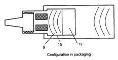
- a further aspect of the capis its ability to be in packaging configuration or use configuration while interfacing with the threaded external luer. To this end, the cap acts as a cover by not substantially overlapping the threaded external valve body in the packaging configuration. However, in the use configuration the cap does substantially overlapping both the vented region and the threaded external luer.
- kitsSuch a kit is made up of a passive vent assembly with a vented body and a luer connection site.
- the passive vent assembly in the kithas a diametrically vented region and a threaded external luer. In the diametrically vented region there are support members that extend between the luer connection site and the threaded external luer.
- the passive vent assemblyhas a cap that acts as a cover. The internal threads for accepting the threaded external luer within the cap assist in the cap's covering ability.
- a further aspect of the capis its ability to exist in a packaging configuration or use configuration while interfacing with the threaded external luer.
- the capacts as a cover not substantially overlapping the threaded external valve body in the packaging configuration.
- the capacts as a cover substantially overlapping both the vented region and the threaded external luer.
- the kitcontains a brachytherapy balloon that comprises a balloon, a catheter shaft, and a brachytherapy port.
- Another embodiment of this inventionin general terms comprises a method for sterilizing a device.
- the first step in the methodincludes providing a passive vent assembly comprising a vented body and a luer connection site.
- the valve fittinghas a diametrically vented region and a threaded external luer.
- In the diametrically vented regionthere are support members that extend between the luer connection site and the threaded external luer.
- the passive vent assemblyhas a cap that acts as a cover.
- the internal threads for accepting the threaded external luer within the capassist in the cap's covering ability.
- a further aspect of the capis its ability to be in a packaging configuration or a use configuration while interfacing with the threaded external luer.
- the capacts as a cover by not substantially overlapping the threaded external valve body in the packaging configuration.
- the capacts as a cover substantially overlapping both the vented region and the threaded external luer.
- a brachytherapy balloon assemblycomprising a balloon, a multi-lumen catheter shaft, and a high-dose-rate brachytherapy port.
- the second step of this methodincludes exposing the passive vent assembly and brachytherapy balloon assembly to a sterilization agent so that the sterilization agent comes into communication with all interior and exterior surfaces of the passive vent assembly, the injection site cap, the balloon, the multi-lumen catheter shaft, and the high-dose-rate brachytherapy port.
- the third step of the methodthen requires maintaining the injection site cap in either the packaging configuration or use configuration while interfacing with the passive vent assembly.
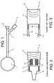
- FIG. 3illustrates a cut away view of one embodiment of the cap on a passive vent valve. Additional representative embodiments of the cap may have differing shapes and sizes.
- FIG. 4illustrates a cut away view of one embodiment of a passive vent valve in the packaging configuration. Additional representative embodiments in the packaging configuration may have differing shapes, sizes interlocking mechanisms between the valve body and cap as well as differing interfaces between the valve body and cap of the device.
- FIG. 5illustrates a cut away view of one embodiment of a needle-free valve in the use configuration that incorporates aspects of the present invention. Additional embodiments also may conform to the use configuration and result in a differing shape and size of the device.
- Embodiments of the inventionare directed to a passive vent assembly having a valve body and cap assembly.
- the valve bodyhas a connection site at an threaded internal luer end and an threaded external luer end.
- the valve bodydefines passageway between the threaded internal luer end and the threaded external luer end.
- the valve bodymay internally contain various one-way or two-way valves that make use of diaphragm or actuation like devices known to those of ordinary skill in the art.
- encircling the valve body diametricallyare multiple open vents between the threaded internal and external luers that provide gaseous passage between the external environment and the internal environment of the valve.
- embodiments of the inventionare directed to a passive vent assembly having a valve body comprising an threaded internal luer with an optionally inserted male luer connection or other connection device.
- the valve bodyalso comprises an threaded external luer. Between both of these luers have vented openings placed diametrically around the valve body. Each vented opening contains a vent material that allows the passage of gas, but not liquids. Examples of material that may be used include high-density polyethylene fibers, olefin fibers or polytetrafluoroethylene such as Gore® and Tyvek®.
- diaphragm devicesthat act as one and two-way valves and actuation mechanisms in limiting the passage of liquids or gases through the device.
- the cap portion of the vented valvepossesses a captive end having an overhanging lip at the end of extended length that intersects the internal captive end threads.
- a cap bodythat may contain valve diaphragm or actuation mechanism that acts as one and two-way valves in limiting the passage of liquids or gases through the device.
- Vented valve assembliessuch as these relate to multi-purpose devices that are adaptable to multiple medical use and device requirements. Such devices are suitable for use with brachytherapy balloons, ports, bags, medicine bottles or vials and lock connectors as well as needle free connectors.
- Other embodiments of the passive vent assemblymay be used in obtaining fluids such as diluents for use in reconstituting medications from vials for delivery to ports, other vials, bags, and tubing through use of needle free transfer systems having the adapter valve device in place.
- Still other embodiments of this devicemay be used with medical devices that require a connection port that must be closed during use, but open during packaging and sterilization.
- Additional embodiments of the inventionalso generally relate to methods of sterilizing a device using sterilization agents using gases or other flowable materials. Such methods allow for the passage of a sterilization agent through and around all surface areas of the passive vent valve. Specifically, these methods allow the fluid sterilization agent to come in contact with all exposed surface areas that are not limited to, but include the valve body and cap.
- the passive vent valvemay be embodied in different configurations and is not limited to any of those configurations disclosed.
- FIG. 1Illustrated in FIG. 1 is an embodiment of a brachytherapy device into which the passive vent valve may be incorporated that includes various aspects of the present invention. Other embodiments may have differing shapes, sizes and points of connection.
- the particular configuration of FIG. 1 as well as all of the figuresis for illustration purposes only.
- FIG. 2Illustrated in FIG. 2 is a cut away view of the valve body 6 .
- the valve bodyconsists of a threaded internal luer end 7 that may also comprise other types of interface locking mechanisms in place of, at or near the threaded internal luer end.
- connection devicessuch as a male luer 8 may be present for connection to the injection path.
- Such connection devicescomprise many forms that enable the valve body to attach to an injection path of various devices.
- the valve body 6comprises an threaded external luer end 9 .
- the threaded external luer end 9may also comprise various other means for attaching the valve body 6 to the cap 12 in FIG. 3 .
- vent openings 10Medially spaced between both the threaded internal luer end 7 and the threaded external luer end 9 are vent openings 10 positioned diametrically around the valve body 6 .
- the vent openings 10are covered in vented mesh materials 11 such as high-density polyethylene fibers, olefin fibers or polytetrafluoroethylene, e.g. Gore® and Tyvek®. All of which may contain specific pore diameters that allow the passage of gas, but not liquid.
- the vent openings 10may possess any shape and size depending on the venting needs.
- the vented mesh material 11may be attached to the valve body 6 by those means known in the art and may vary depending on the type of vented mesh material 11 incorporated the valve body 6 design.
- valve body 6there may be various diaphragm or actuation type devices that limit the flow of liquid or gas through the valve body 6 .
- Such devicesinclude but are not limited to one-way valves and two-way valves.
- Representative materials from which the valve body 6 is madeinclude: polycarbonate, PVC, acrylic, polypropylene, PET, polytetrafluoroethylene (PTFE), glass-filled PTFE, ethylene polypropylene, flourosilicone, or other thermoplastics known to those of ordinary skill in the art.
- FIG. 3illustrates a cut away of the cap 12 portion of the passive vent valve.
- the capconsists of a captive end 13 for receiving the valve body 6 .
- the captive end of the devicepossesses and overhanging lip 14 that may be of varying shapes and sizes necessary to secure the valve body to the cap.
- Extending inside the captive end 13there is a traversing region 15 in which the valve body 6 is placed when in the packaging configuration as shown in FIG. 4 .
- the internal captive end threads 16for securing the threaded external luer end 9 of the valve body 6 to the cap 12 .
- In the region of the internal captive threads 16there may be additional means for securing the valve body 6 to the cap 12 so that valve body and cap may be placed in the use configuration as shown in FIG.
- the opposite end of the cap 12possesses an externally threaded injection site interface 18 .
- the region of the externally threaded injection site interface 18may possess other means known to those of ordinary skill in the art for attaching various devices to the cap 12 and is not limited to a thread-type design.
- various diaphragm or actuation type devicesthat limit the flow of liquid or gas through the cap body 17 .
- Such devicesinclude but are not limited to one-way valves and two-way valves.
- Representative materials from which the cap body 12 is madeinclude: polycarbonate, PVC, acrylic, polypropylene, PET or other thermoplastics known to those of ordinary skill in the art.
- FIG. 4represents the combined valve body and cap in the packaging configuration.
- the threaded external luer of the valve body 6is inserted within the captive end 13 of the cap 12 .
- the threaded external luer end 9 of the valve body 6is positioned at the traversing region 15 of the cap 12 allowing for a space to exist between the threaded external luer end 9 of the valve body 6 and the internal cap end threads 16 of the cap 12 .
- the overhanging lip 14 of the cap 12effectively allows the cap 12 to be secured to the valve body 6 thereby inhibiting it from being pulled off or removed.
- the diametrically placed vents 10 containing the vented mesh material 11allow gaseous flow through the valve body 6 contacting all surface areas of the cap 12 and the valve body 6 both internally and externally.
- gaseous flowmay enter through the threaded internal luer end 7 or through openings such as the luer connection 8 secured within the threaded internal luer end 7 to internal portions of the passive vent device.
- gaseous flowmay proceed through the vented mesh material 11 and through the internal portion of the valve body 6 to the open packaging configuration compartment 19 . Gaseous flow may also flow through and around the threaded external injection site interface 18 to contact all surface that are exposed.
- FIG. 5represents the combined cap 12 and valve 6 in the use configuration.
- the threaded external luer end of the valve body 6is inserted within the captive end 13 of the cap 12 .
- the threaded external luer end 9 of the valve body 6is secured to the internal captive end threads 16 of the cap 12 eliminating any space from existing between the threaded external luer end 9 of the valve body 6 and the internal captive end threads 16 of the cap 12 .
- the overhanging lip 14 and traversing region 15 of the cap 12extend over the diametrically placed vented region 10 effectively sealing any gas or liquid from crossing the vented mesh 11 .
- the overhanging lip 14 and traversing region 15may extend over the exterior sealing region 20 .
- the exterior sealing region 20may also be coated with or contain materials that ensure a proper seal is made to prevent any leakage between the cap 12 and the valve body 6 .
- materialsinclude silicon, viton, buna-n, silicone, neoprene, urethane, and other gasket and soft durometer materials known to those of ordinary skill in the art.
- the diametrically placed vents 10 containing the vented mesh material 11are covered by the overhanging lip 14 and the traversing region 15 creating a sealed system functioning as a one-way or two-way valve or actuation device.
- Preferred embodimentsinclude a passive vent assembly wherein the vented region is interspersed with support members that comprise multiple individual vents.
- the ventscomprise a fluid impermeable membrane that is made up of high density polyethylene fibers, olefin fibers or poly tetrafluoroethylene.
- Each of the materials making up the ventshave pore sizes of 0.1 micron and larger.
- the preferred embodiments of this inventionpossess a male luer connection on the valve body.
- An additional embodiment of the inventionincludes a method of sterilizing a device.
- sterilizing gaspasses around the exterior of the device and through the vented mesh material 11 , through the male luer connection 8 or opening present where the male luer connection would be inserted, and through the opening located internally to the threaded external injection site interface 18 . Once the gas passes into and around the exterior of the device. All of the surface areas exposed to the gas are then sterilized both internally and externally.
- Methods such as those encompassed by embodiments of the claimed inventionmake use of ethylene oxide as a sterilization agent.
- additional means of gas sterilizationuse plasma/hydrogen peroxide gas, ozone and chlorine dioxide.
- other methods of sterilizationinclude radiation and e-beam processes, pulsed UV light, x-ray and gamma irradiation, electron beam, steam and heat processes, autoclaves and dry heat. Each of which may be combined or performed separately.
- ethylene oxideis the state of the art in sterilizing devices.
- the relatively low process temperaturein comparison to steam sterilization has made ethylene oxide an excellent means for sterilizing many products.
- ethylene oxidemakes it an ideal sterilizing agent. This property, however, also makes it extremely dangerous at ambient oxygen levels.
- a set of evacuations coupled with steam additionsis executed at the start of every sterilization procedure. Ethylene oxide gas is then added and allowed to sit with the product being sterilized. During this point in the method, the ethylene oxide comes in contact with all of the surface areas of the passive vent assembly. During this “sitting phase” or “gas dwell phase” the product and its packaging absorb ethylene oxide gas. Following the gas dwell phase, a series of evacuations and air infusions occur. This helps in the removal of gas from the product.
- the productis then transferred to an aeration chamber where ethylene oxide and ethylene oxide degradation products dissipate safely from the product.
- this gas dissipation periodmay last from several hours to weeks and even months.
- the gasis evacuated from the chamber and the product is removed.
- the preferred embodiment of the methoduses ethylene oxide gas for sterilizing the device.
Landscapes
- Health & Medical Sciences (AREA)
- Life Sciences & Earth Sciences (AREA)
- Animal Behavior & Ethology (AREA)
- General Health & Medical Sciences (AREA)
- Public Health (AREA)
- Veterinary Medicine (AREA)
- Epidemiology (AREA)
- Chemical & Material Sciences (AREA)
- Chemical Kinetics & Catalysis (AREA)
- General Chemical & Material Sciences (AREA)
- Engineering & Computer Science (AREA)
- Biomedical Technology (AREA)
- Pathology (AREA)
- Nuclear Medicine, Radiotherapy & Molecular Imaging (AREA)
- Radiology & Medical Imaging (AREA)
- Physics & Mathematics (AREA)
- Plasma & Fusion (AREA)
- Infusion, Injection, And Reservoir Apparatuses (AREA)
Abstract
Description
Claims (19)
Priority Applications (2)
| Application Number | Priority Date | Filing Date | Title |
|---|---|---|---|
| US12/389,577US8403822B2 (en) | 2009-02-20 | 2009-02-20 | Passive vent for brachytherapy balloon catheters |
| PCT/US2010/024786WO2010096687A1 (en) | 2009-02-20 | 2010-02-19 | Passive vent for brachytherapy balloon catheters |
Applications Claiming Priority (1)
| Application Number | Priority Date | Filing Date | Title |
|---|---|---|---|
| US12/389,577US8403822B2 (en) | 2009-02-20 | 2009-02-20 | Passive vent for brachytherapy balloon catheters |
Publications (2)
| Publication Number | Publication Date |
|---|---|
| US20100217064A1 US20100217064A1 (en) | 2010-08-26 |
| US8403822B2true US8403822B2 (en) | 2013-03-26 |
Family
ID=42631548
Family Applications (1)
| Application Number | Title | Priority Date | Filing Date |
|---|---|---|---|
| US12/389,577Active2031-07-14US8403822B2 (en) | 2009-02-20 | 2009-02-20 | Passive vent for brachytherapy balloon catheters |
Country Status (2)
| Country | Link |
|---|---|
| US (1) | US8403822B2 (en) |
| WO (1) | WO2010096687A1 (en) |
Cited By (3)
| Publication number | Priority date | Publication date | Assignee | Title |
|---|---|---|---|---|
| US20180015251A1 (en)* | 2010-09-09 | 2018-01-18 | University Of Florida Research Foundation, Incorporated | Context-sensitive flow interrupter and drainage outflow optimization system |
| US10675440B2 (en) | 2016-02-18 | 2020-06-09 | Smiths Medical Asd, Inc. | Closed system catheter |
| US12048541B2 (en) | 2018-06-08 | 2024-07-30 | Smiths Medical Asd, Inc. | Blood sequestration device and method |
Families Citing this family (1)
| Publication number | Priority date | Publication date | Assignee | Title |
|---|---|---|---|---|
| US7947014B2 (en)* | 2009-05-15 | 2011-05-24 | Tai Kien | Relief valve for use with a balloon catheter |
Citations (46)
| Publication number | Priority date | Publication date | Assignee | Title |
|---|---|---|---|---|
| US3192949A (en) | 1962-07-10 | 1965-07-06 | Halkey Roberts Corp | Spring biased check valve |
| US3385301A (en) | 1965-10-11 | 1968-05-28 | American Hospital Supply Corp | Balloon catheter having a deformable one-way inflation valve |
| US3570484A (en) | 1967-08-31 | 1971-03-16 | Eschmann Bros & Walsh Ltd | Intravenous valve assembly |
| US3831629A (en) | 1972-01-24 | 1974-08-27 | Halkey Roberts Corp | Check valve |
| US3986508A (en)* | 1973-08-22 | 1976-10-19 | Abcor, Inc. | Sterilizable, medical connector for blood processing |
| US4123091A (en)* | 1977-11-21 | 1978-10-31 | Renal Systems, Inc. | Tube connector |
| US4154342A (en)* | 1976-07-30 | 1979-05-15 | Boehringer Ingelheim Gmbh | Sterilizable package |
| US4222407A (en) | 1978-09-13 | 1980-09-16 | Baxter Travenol Laboratories, Inc. | One-way flex valve |
| US4246932A (en) | 1979-10-18 | 1981-01-27 | Burron Medical, Inc. | Multiple additive valve assembly |
| US4286628A (en) | 1979-06-21 | 1981-09-01 | Nypro, Inc. | Control of fluid flow using longitudinally movable disc |
| US4310017A (en) | 1980-01-30 | 1982-01-12 | Burron Medical Inc. | Backflow check valve for use with IV administration sets |
| US4369812A (en) | 1981-02-18 | 1983-01-25 | Nypro Inc. | Control of fluid flow using precisely positioned disc |
| US4535820A (en) | 1984-05-24 | 1985-08-20 | Burron Medical Inc. | Normally closed check valve |
| US4610469A (en)* | 1983-02-02 | 1986-09-09 | Steritech B.V. | Connector assembly for sterile connection or two internally sterile containers of tubings |
| US4683916A (en) | 1986-09-25 | 1987-08-04 | Burron Medical Inc. | Normally closed automatic reflux valve |
| US5423791A (en) | 1992-03-31 | 1995-06-13 | Bartlett; J. Mark | Valve device for medical fluid transfer |
| US5931774A (en)* | 1991-06-14 | 1999-08-03 | Proxima Therapeutics, Inc. | Inflatable devices for tumor treatment |
| US5964261A (en) | 1996-05-29 | 1999-10-12 | Baxter International Inc. | Implantation assembly |
| US20010047187A1 (en)* | 1998-11-06 | 2001-11-29 | Neomend, Inc. | Systems, methods, and compositions for achieving closure of vascular puncture sites |
| US20020019608A1 (en)* | 1999-06-16 | 2002-02-14 | Mason Bradley R. | Patient-controlled medication delivery system with overmedication prevention |
| US6482188B1 (en) | 1999-10-01 | 2002-11-19 | Mission Medical Devices, Inc. | Nonvented needle-free injection valve |
| US20030230309A1 (en)* | 2002-06-18 | 2003-12-18 | Lma International, Sa | Automatic high temperature venting for inflatable medical devices |
| US20040073171A1 (en) | 2002-10-10 | 2004-04-15 | Rogers Bobby E. | Needle-free valve and catheter assembly |
| US20040138626A1 (en)* | 1996-11-18 | 2004-07-15 | Cote Andrew L. | Luer-activated valve |
| US20040143226A1 (en)* | 2003-01-16 | 2004-07-22 | Becton, Dickinson And Company | Blood collection set with venting mechanism |
| US20040158211A1 (en) | 2003-02-07 | 2004-08-12 | Rogers Bobby E. | Closed system catheterization assembly and related methods |
| US6875205B2 (en) | 2002-02-08 | 2005-04-05 | Alaris Medical Systems, Inc. | Vial adapter having a needle-free valve for use with vial closures of different sizes |
| US20050101920A1 (en)* | 2003-11-06 | 2005-05-12 | Paul Keane | Plunger rod for arterial blood collection syringes |
| US20050245872A1 (en)* | 2004-04-28 | 2005-11-03 | Vasogen Ireland Limited | Multi-outlet medical dispensing device |
| US20050273019A1 (en)* | 2004-06-02 | 2005-12-08 | Becton, Dickinson And Company | Blood collection set with venting mechanism |
| US20060192164A1 (en) | 2005-02-14 | 2006-08-31 | Korogi Todd M | Valved fluid connector |
| US20060253090A1 (en) | 2005-05-04 | 2006-11-09 | Bradley Arthur J | Method and apparatus for facilitating evacuation and cleansing of a colonostomy bag |
| US20060271015A1 (en)* | 2005-05-09 | 2006-11-30 | Mantell Robert R | High-flow luer lock connector for a luer lock connection |
| US20060276770A1 (en) | 2005-05-13 | 2006-12-07 | Bob Rogers | Medical substance transfer system |
| US20070083162A1 (en) | 2005-10-11 | 2007-04-12 | Span-America Medical Systems, Inc. | Valve for intravenous catheter |
| US20070156112A1 (en) | 2005-12-30 | 2007-07-05 | Walsh Mary K | Medical vial adapter with reduced diameter cannula and enlarged vent lumen |
| US20070260104A1 (en) | 2006-05-08 | 2007-11-08 | Bretz Phillip | Autologous fat pad transfer for use with partial breast irradiation |
| US7306199B2 (en) | 2001-11-29 | 2007-12-11 | Cardinal Health 303, Inc. | Needle free medical connector with expanded valve mechanism and method of fluid flow control |
| US7319735B2 (en) | 2001-10-19 | 2008-01-15 | Hologic, Inc. | Mammography system and method employing offset compression paddles, automatic collimation, and retractable anti-scatter grid |
| US20080023346A1 (en)* | 2004-06-10 | 2008-01-31 | Design & Performance - Cyprus Limited | Protected Stent Delivery System and Packaging |
| US20080146861A1 (en)* | 2006-12-18 | 2008-06-19 | Goshen Health System, Inc. | Brachytherapy Shielding System |
| WO2009027394A1 (en)* | 2007-08-29 | 2009-03-05 | Acrostak Corp. | Method and kit for delivery of brachytherapy to a subject |
| US7520489B2 (en)* | 2003-06-17 | 2009-04-21 | Filtertek Inc. | Fluid handling device and method of making same |
| US20090118681A1 (en)* | 2007-10-30 | 2009-05-07 | William Cook Europe, Aps | Haemostatic valve |
| US7803140B2 (en)* | 2005-07-06 | 2010-09-28 | Icu Medical, Inc. | Medical connector with closeable male luer |
| US20100292640A1 (en)* | 2009-05-15 | 2010-11-18 | Tai Kien | Relief valve for use with a balloon catheter |
- 2009
- 2009-02-20USUS12/389,577patent/US8403822B2/enactiveActive
- 2010
- 2010-02-19WOPCT/US2010/024786patent/WO2010096687A1/enactiveApplication Filing
Patent Citations (50)
| Publication number | Priority date | Publication date | Assignee | Title |
|---|---|---|---|---|
| US3192949A (en) | 1962-07-10 | 1965-07-06 | Halkey Roberts Corp | Spring biased check valve |
| US3385301A (en) | 1965-10-11 | 1968-05-28 | American Hospital Supply Corp | Balloon catheter having a deformable one-way inflation valve |
| US3570484A (en) | 1967-08-31 | 1971-03-16 | Eschmann Bros & Walsh Ltd | Intravenous valve assembly |
| US3831629A (en) | 1972-01-24 | 1974-08-27 | Halkey Roberts Corp | Check valve |
| US3986508A (en)* | 1973-08-22 | 1976-10-19 | Abcor, Inc. | Sterilizable, medical connector for blood processing |
| US4154342A (en)* | 1976-07-30 | 1979-05-15 | Boehringer Ingelheim Gmbh | Sterilizable package |
| US4123091A (en)* | 1977-11-21 | 1978-10-31 | Renal Systems, Inc. | Tube connector |
| US4222407A (en) | 1978-09-13 | 1980-09-16 | Baxter Travenol Laboratories, Inc. | One-way flex valve |
| US4286628A (en) | 1979-06-21 | 1981-09-01 | Nypro, Inc. | Control of fluid flow using longitudinally movable disc |
| US4246932A (en) | 1979-10-18 | 1981-01-27 | Burron Medical, Inc. | Multiple additive valve assembly |
| US4310017A (en) | 1980-01-30 | 1982-01-12 | Burron Medical Inc. | Backflow check valve for use with IV administration sets |
| US4369812A (en) | 1981-02-18 | 1983-01-25 | Nypro Inc. | Control of fluid flow using precisely positioned disc |
| US4610469A (en)* | 1983-02-02 | 1986-09-09 | Steritech B.V. | Connector assembly for sterile connection or two internally sterile containers of tubings |
| US4535820A (en) | 1984-05-24 | 1985-08-20 | Burron Medical Inc. | Normally closed check valve |
| US4683916A (en) | 1986-09-25 | 1987-08-04 | Burron Medical Inc. | Normally closed automatic reflux valve |
| US5931774A (en)* | 1991-06-14 | 1999-08-03 | Proxima Therapeutics, Inc. | Inflatable devices for tumor treatment |
| US5423791A (en) | 1992-03-31 | 1995-06-13 | Bartlett; J. Mark | Valve device for medical fluid transfer |
| US5964261A (en) | 1996-05-29 | 1999-10-12 | Baxter International Inc. | Implantation assembly |
| US20040138626A1 (en)* | 1996-11-18 | 2004-07-15 | Cote Andrew L. | Luer-activated valve |
| US20010047187A1 (en)* | 1998-11-06 | 2001-11-29 | Neomend, Inc. | Systems, methods, and compositions for achieving closure of vascular puncture sites |
| US20020019608A1 (en)* | 1999-06-16 | 2002-02-14 | Mason Bradley R. | Patient-controlled medication delivery system with overmedication prevention |
| US6482188B1 (en) | 1999-10-01 | 2002-11-19 | Mission Medical Devices, Inc. | Nonvented needle-free injection valve |
| US7319735B2 (en) | 2001-10-19 | 2008-01-15 | Hologic, Inc. | Mammography system and method employing offset compression paddles, automatic collimation, and retractable anti-scatter grid |
| US7306199B2 (en) | 2001-11-29 | 2007-12-11 | Cardinal Health 303, Inc. | Needle free medical connector with expanded valve mechanism and method of fluid flow control |
| US20050148994A1 (en)* | 2002-02-08 | 2005-07-07 | Leinsing Karl R. | Vial adapter having a needle-free valve for use with vial closures of different sizes |
| US6875205B2 (en) | 2002-02-08 | 2005-04-05 | Alaris Medical Systems, Inc. | Vial adapter having a needle-free valve for use with vial closures of different sizes |
| US20030230309A1 (en)* | 2002-06-18 | 2003-12-18 | Lma International, Sa | Automatic high temperature venting for inflatable medical devices |
| US20040073171A1 (en) | 2002-10-10 | 2004-04-15 | Rogers Bobby E. | Needle-free valve and catheter assembly |
| US20040143226A1 (en)* | 2003-01-16 | 2004-07-22 | Becton, Dickinson And Company | Blood collection set with venting mechanism |
| US6979323B2 (en) | 2003-02-07 | 2005-12-27 | Aragon Medical Corporation | Closed system catheterization assembly and related methods |
| US20060155258A1 (en) | 2003-02-07 | 2006-07-13 | Aragon Medical Corporation | Closed system catheterization assembly and related methods |
| US20040158211A1 (en) | 2003-02-07 | 2004-08-12 | Rogers Bobby E. | Closed system catheterization assembly and related methods |
| US7520489B2 (en)* | 2003-06-17 | 2009-04-21 | Filtertek Inc. | Fluid handling device and method of making same |
| US20050101920A1 (en)* | 2003-11-06 | 2005-05-12 | Paul Keane | Plunger rod for arterial blood collection syringes |
| US20050245872A1 (en)* | 2004-04-28 | 2005-11-03 | Vasogen Ireland Limited | Multi-outlet medical dispensing device |
| US20050273019A1 (en)* | 2004-06-02 | 2005-12-08 | Becton, Dickinson And Company | Blood collection set with venting mechanism |
| US20080023346A1 (en)* | 2004-06-10 | 2008-01-31 | Design & Performance - Cyprus Limited | Protected Stent Delivery System and Packaging |
| US20060192164A1 (en) | 2005-02-14 | 2006-08-31 | Korogi Todd M | Valved fluid connector |
| US20060253090A1 (en) | 2005-05-04 | 2006-11-09 | Bradley Arthur J | Method and apparatus for facilitating evacuation and cleansing of a colonostomy bag |
| US20060271015A1 (en)* | 2005-05-09 | 2006-11-30 | Mantell Robert R | High-flow luer lock connector for a luer lock connection |
| US20060276770A1 (en) | 2005-05-13 | 2006-12-07 | Bob Rogers | Medical substance transfer system |
| US7803140B2 (en)* | 2005-07-06 | 2010-09-28 | Icu Medical, Inc. | Medical connector with closeable male luer |
| US20070083162A1 (en) | 2005-10-11 | 2007-04-12 | Span-America Medical Systems, Inc. | Valve for intravenous catheter |
| US20070156112A1 (en) | 2005-12-30 | 2007-07-05 | Walsh Mary K | Medical vial adapter with reduced diameter cannula and enlarged vent lumen |
| US20070260104A1 (en) | 2006-05-08 | 2007-11-08 | Bretz Phillip | Autologous fat pad transfer for use with partial breast irradiation |
| US20080146861A1 (en)* | 2006-12-18 | 2008-06-19 | Goshen Health System, Inc. | Brachytherapy Shielding System |
| WO2009027394A1 (en)* | 2007-08-29 | 2009-03-05 | Acrostak Corp. | Method and kit for delivery of brachytherapy to a subject |
| US20090118681A1 (en)* | 2007-10-30 | 2009-05-07 | William Cook Europe, Aps | Haemostatic valve |
| US20100292640A1 (en)* | 2009-05-15 | 2010-11-18 | Tai Kien | Relief valve for use with a balloon catheter |
| US7947014B2 (en)* | 2009-05-15 | 2011-05-24 | Tai Kien | Relief valve for use with a balloon catheter |
Non-Patent Citations (8)
| Title |
|---|
| "About Brachytherapy: What is Brachytherapy", American Brachytherapy Society, Accessed May 28, 2008. |
| "Brachytherapy", Radiology Info, Accessed May 28, 2008. |
| "Brachytherapy", Wikipedia the free enclyclopedia, Accessed May 28, 2008. |
| "ETO Sterilization", Medical Device Link, Accessed Nov. 8, 2007. |
| "Keeping I.V. therapy safe with needless systems", Nursing, Accessed Jun. 24, 2008. |
| "Overview of Sterilization Procedures", Medical Device Link, Accessed Dec. 22, 2008. |
| DuPont Medical Packaging Technical Reference Guide, (Jan. 2007). |
| Material Comparison Chart, Date unknown. |
Cited By (5)
| Publication number | Priority date | Publication date | Assignee | Title |
|---|---|---|---|---|
| US20180015251A1 (en)* | 2010-09-09 | 2018-01-18 | University Of Florida Research Foundation, Incorporated | Context-sensitive flow interrupter and drainage outflow optimization system |
| US10722679B2 (en)* | 2010-09-09 | 2020-07-28 | University Of Florida Research Foundation, Incorporated | Context-sensitive flow interrupter and drainage outflow optimization system |
| US10675440B2 (en) | 2016-02-18 | 2020-06-09 | Smiths Medical Asd, Inc. | Closed system catheter |
| US12343482B2 (en) | 2016-02-18 | 2025-07-01 | Icu Medical, Inc. | Closed system catheter |
| US12048541B2 (en) | 2018-06-08 | 2024-07-30 | Smiths Medical Asd, Inc. | Blood sequestration device and method |
Also Published As
| Publication number | Publication date |
|---|---|
| WO2010096687A1 (en) | 2010-08-26 |
| US20100217064A1 (en) | 2010-08-26 |
Similar Documents
| Publication | Publication Date | Title |
|---|---|---|
| US8523826B2 (en) | Luer-type needle-free valve fitting with bypass | |
| AU2019200796B2 (en) | System for Enhanced Sealing of Coupled Medical Fluid Lines and Method | |
| US11724085B2 (en) | Catheter connection system for ultraviolet light disinfection | |
| JP6355758B2 (en) | System having an adapter for closed transfer of fluid | |
| ES2564992T3 (en) | UV-C antimicrobial device for intravenous therapy | |
| US20050147524A1 (en) | Sterile tubing termination assembly | |
| AU2013232371B2 (en) | Catheter adapter port valve | |
| US12186466B2 (en) | Transfer catheter for ultraviolet disinfection | |
| US20050147525A1 (en) | Sanitized tubing termination method and assembly | |
| EP2846754B1 (en) | Prefilled container systems | |
| JP6984034B2 (en) | Connection arrangement for closed system transfer of fluids | |
| CN108324567A (en) | Protective cap and syringe adapter with protective cap | |
| AU2019259768A1 (en) | Access and vapor containment system for a drug vial and method of making and using same | |
| US8403822B2 (en) | Passive vent for brachytherapy balloon catheters | |
| CN108324568A (en) | Syringe Adapter | |
| ES2373960T3 (en) | APPARATUS TO ADJUST AND REMOVE CLOSURE MEANS IN A FINAL PART OF A TUBULAR ELEMENT FOR PERITONEAL DIALYSIS. | |
| US20220339423A1 (en) | Medical connector with automatic sealing on disconnection | |
| US20230008738A1 (en) | Three-way urology catheter stopcock and urology catheter stopcock assembly | |
| WO2014210418A1 (en) | Sterility retaining medical connector assembly and method | |
| CN113423351A (en) | Medical device inflation connector | |
| ES2951397T3 (en) | Piston valves for series-connectable drug modules of a combinatorial drug delivery device | |
| KR20250138033A (en) | 3-way stopcock | |
| KR20240088424A (en) | Infusion set with a branch pipe to disinfect contaminated needles | |
| NZ750767A (en) | System for enhanced sealing of coupled medical fluid lines and method |
Legal Events
| Date | Code | Title | Description |
|---|---|---|---|
| AS | Assignment | Owner name:CYTYC CORPORATION, MASSACHUSETTS Free format text:ASSIGNMENT OF ASSIGNORS INTEREST;ASSIGNORS:BENSON, MARIA;ALLAN, DONNA;OCAMPO, WALTER;SIGNING DATES FROM 20090212 TO 20090218;REEL/FRAME:022289/0060 | |
| AS | Assignment | Owner name:GOLDMAN SACHS BANK USA, NEW YORK Free format text:SECURITY AGREEMENT;ASSIGNORS:HOLOGIC, INC.;BIOLUCENT, LLC;CYTYC CORPORATION;AND OTHERS;REEL/FRAME:028810/0745 Effective date:20120801 | |
| STCF | Information on status: patent grant | Free format text:PATENTED CASE | |
| AS | Assignment | Owner name:CYTYC SURGICAL PRODUCTS, LIMITED PARTNERSHIP, MASSACHUSETTS Free format text:SECURITY INTEREST RELEASE REEL/FRAME 028810/0745;ASSIGNOR:GOLDMAN SACHS BANK USA, AS COLLATERAL AGENT;REEL/FRAME:035820/0239 Effective date:20150529 Owner name:CYTYC CORPORATION, MASSACHUSETTS Free format text:SECURITY INTEREST RELEASE REEL/FRAME 028810/0745;ASSIGNOR:GOLDMAN SACHS BANK USA, AS COLLATERAL AGENT;REEL/FRAME:035820/0239 Effective date:20150529 Owner name:HOLOGIC, INC., MASSACHUSETTS Free format text:SECURITY INTEREST RELEASE REEL/FRAME 028810/0745;ASSIGNOR:GOLDMAN SACHS BANK USA, AS COLLATERAL AGENT;REEL/FRAME:035820/0239 Effective date:20150529 Owner name:GEN-PROBE INCORPORATED, MASSACHUSETTS Free format text:SECURITY INTEREST RELEASE REEL/FRAME 028810/0745;ASSIGNOR:GOLDMAN SACHS BANK USA, AS COLLATERAL AGENT;REEL/FRAME:035820/0239 Effective date:20150529 Owner name:BIOLUCENT, LLC, MASSACHUSETTS Free format text:SECURITY INTEREST RELEASE REEL/FRAME 028810/0745;ASSIGNOR:GOLDMAN SACHS BANK USA, AS COLLATERAL AGENT;REEL/FRAME:035820/0239 Effective date:20150529 Owner name:SUROS SURGICAL SYSTEMS, INC., MASSACHUSETTS Free format text:SECURITY INTEREST RELEASE REEL/FRAME 028810/0745;ASSIGNOR:GOLDMAN SACHS BANK USA, AS COLLATERAL AGENT;REEL/FRAME:035820/0239 Effective date:20150529 Owner name:CYTYC SURGICAL PRODUCTS, LIMITED PARTNERSHIP, MASS Free format text:SECURITY INTEREST RELEASE REEL/FRAME 028810/0745;ASSIGNOR:GOLDMAN SACHS BANK USA, AS COLLATERAL AGENT;REEL/FRAME:035820/0239 Effective date:20150529 Owner name:THIRD WAVE TECHNOLOGIES, INC., MASSACHUSETTS Free format text:SECURITY INTEREST RELEASE REEL/FRAME 028810/0745;ASSIGNOR:GOLDMAN SACHS BANK USA, AS COLLATERAL AGENT;REEL/FRAME:035820/0239 Effective date:20150529 | |
| AS | Assignment | Owner name:BANK OF AMERICA, N.A., AS COLLATERAL AGENT, NORTH CAROLINA Free format text:SECURITY AGREEMENT;ASSIGNORS:HOLOGIC, INC.;BIOLUCENT, LLC;CYTYC CORPORATION;AND OTHERS;REEL/FRAME:036307/0199 Effective date:20150529 Owner name:BANK OF AMERICA, N.A., AS COLLATERAL AGENT, NORTH Free format text:SECURITY AGREEMENT;ASSIGNORS:HOLOGIC, INC.;BIOLUCENT, LLC;CYTYC CORPORATION;AND OTHERS;REEL/FRAME:036307/0199 Effective date:20150529 | |
| FPAY | Fee payment | Year of fee payment:4 | |
| AS | Assignment | Owner name:CYTYC SURGICAL PRODUCTS, LIMITED PARTNERSHIP, MASSACHUSETTS Free format text:CORRECTIVE ASSIGNMENT TO CORRECT THE INCORRECT PATENT NO. 8081301 PREVIOUSLY RECORDED AT REEL: 035820 FRAME: 0239. ASSIGNOR(S) HEREBY CONFIRMS THE SECURITY INTEREST RELEASE;ASSIGNOR:GOLDMAN SACHS BANK USA, AS COLLATERAL AGENT;REEL/FRAME:044727/0529 Effective date:20150529 Owner name:GOLDMAN SACHS BANK USA, NEW YORK Free format text:CORRECTIVE ASSIGNMENT TO CORRECT THE INCORRECT PATENT NO. 8081301 PREVIOUSLY RECORDED AT REEL: 028810 FRAME: 0745. ASSIGNOR(S) HEREBY CONFIRMS THE SECURITY AGREEMENT;ASSIGNORS:HOLOGIC, INC.;BIOLUCENT, LLC;CYTYC CORPORATION;AND OTHERS;REEL/FRAME:044432/0565 Effective date:20120801 Owner name:BIOLUCENT, LLC, MASSACHUSETTS Free format text:CORRECTIVE ASSIGNMENT TO CORRECT THE INCORRECT PATENT NO. 8081301 PREVIOUSLY RECORDED AT REEL: 035820 FRAME: 0239. ASSIGNOR(S) HEREBY CONFIRMS THE SECURITY INTEREST RELEASE;ASSIGNOR:GOLDMAN SACHS BANK USA, AS COLLATERAL AGENT;REEL/FRAME:044727/0529 Effective date:20150529 Owner name:HOLOGIC, INC., MASSACHUSETTS Free format text:CORRECTIVE ASSIGNMENT TO CORRECT THE INCORRECT PATENT NO. 8081301 PREVIOUSLY RECORDED AT REEL: 035820 FRAME: 0239. ASSIGNOR(S) HEREBY CONFIRMS THE SECURITY INTEREST RELEASE;ASSIGNOR:GOLDMAN SACHS BANK USA, AS COLLATERAL AGENT;REEL/FRAME:044727/0529 Effective date:20150529 Owner name:SUROS SURGICAL SYSTEMS, INC., MASSACHUSETTS Free format text:CORRECTIVE ASSIGNMENT TO CORRECT THE INCORRECT PATENT NO. 8081301 PREVIOUSLY RECORDED AT REEL: 035820 FRAME: 0239. ASSIGNOR(S) HEREBY CONFIRMS THE SECURITY INTEREST RELEASE;ASSIGNOR:GOLDMAN SACHS BANK USA, AS COLLATERAL AGENT;REEL/FRAME:044727/0529 Effective date:20150529 Owner name:THIRD WAVE TECHNOLOGIES, INC., MASSACHUSETTS Free format text:CORRECTIVE ASSIGNMENT TO CORRECT THE INCORRECT PATENT NO. 8081301 PREVIOUSLY RECORDED AT REEL: 035820 FRAME: 0239. ASSIGNOR(S) HEREBY CONFIRMS THE SECURITY INTEREST RELEASE;ASSIGNOR:GOLDMAN SACHS BANK USA, AS COLLATERAL AGENT;REEL/FRAME:044727/0529 Effective date:20150529 Owner name:CYTYC CORPORATION, MASSACHUSETTS Free format text:CORRECTIVE ASSIGNMENT TO CORRECT THE INCORRECT PATENT NO. 8081301 PREVIOUSLY RECORDED AT REEL: 035820 FRAME: 0239. ASSIGNOR(S) HEREBY CONFIRMS THE SECURITY INTEREST RELEASE;ASSIGNOR:GOLDMAN SACHS BANK USA, AS COLLATERAL AGENT;REEL/FRAME:044727/0529 Effective date:20150529 Owner name:GEN-PROBE INCORPORATED, MASSACHUSETTS Free format text:CORRECTIVE ASSIGNMENT TO CORRECT THE INCORRECT PATENT NO. 8081301 PREVIOUSLY RECORDED AT REEL: 035820 FRAME: 0239. ASSIGNOR(S) HEREBY CONFIRMS THE SECURITY INTEREST RELEASE;ASSIGNOR:GOLDMAN SACHS BANK USA, AS COLLATERAL AGENT;REEL/FRAME:044727/0529 Effective date:20150529 Owner name:CYTYC SURGICAL PRODUCTS, LIMITED PARTNERSHIP, MASS Free format text:CORRECTIVE ASSIGNMENT TO CORRECT THE INCORRECT PATENT NO. 8081301 PREVIOUSLY RECORDED AT REEL: 035820 FRAME: 0239. ASSIGNOR(S) HEREBY CONFIRMS THE SECURITY INTEREST RELEASE;ASSIGNOR:GOLDMAN SACHS BANK USA, AS COLLATERAL AGENT;REEL/FRAME:044727/0529 Effective date:20150529 | |
| MAFP | Maintenance fee payment | Free format text:PAYMENT OF MAINTENANCE FEE, 8TH YEAR, LARGE ENTITY (ORIGINAL EVENT CODE: M1552); ENTITY STATUS OF PATENT OWNER: LARGE ENTITY Year of fee payment:8 | |
| MAFP | Maintenance fee payment | Free format text:PAYMENT OF MAINTENANCE FEE, 12TH YEAR, LARGE ENTITY (ORIGINAL EVENT CODE: M1553); ENTITY STATUS OF PATENT OWNER: LARGE ENTITY Year of fee payment:12 |