US8403431B2 - Telecommunications enclosures - Google Patents
Telecommunications enclosuresDownload PDFInfo
- Publication number
- US8403431B2 US8403431B2US12/552,045US55204509AUS8403431B2US 8403431 B2US8403431 B2US 8403431B2US 55204509 AUS55204509 AUS 55204509AUS 8403431 B2US8403431 B2US 8403431B2
- Authority
- US
- United States
- Prior art keywords
- enclosure
- frame
- corner
- frame members
- gasket
- Prior art date
- Legal status (The legal status is an assumption and is not a legal conclusion. Google has not performed a legal analysis and makes no representation as to the accuracy of the status listed.)
- Active, expires
Links
- 230000006835compressionEffects0.000claimsdescription8
- 238000007906compressionMethods0.000claimsdescription8
- 241000039077CopulaSpecies0.000description60
- 239000010410layerSubstances0.000description12
- 239000000463materialSubstances0.000description9
- 238000000034methodMethods0.000description8
- 230000008878couplingEffects0.000description4
- 238000010168coupling processMethods0.000description4
- 238000005859coupling reactionMethods0.000description4
- 229910000831SteelInorganic materials0.000description3
- 229910052782aluminiumInorganic materials0.000description3
- XAGFODPZIPBFFR-UHFFFAOYSA-NaluminiumChemical compound[Al]XAGFODPZIPBFFR-UHFFFAOYSA-N0.000description3
- 239000010959steelSubstances0.000description3
- 239000000428dustSubstances0.000description2
- 230000007613environmental effectEffects0.000description2
- 238000007789sealingMethods0.000description2
- 239000004793PolystyreneSubstances0.000description1
- 238000004026adhesive bondingMethods0.000description1
- 238000005266castingMethods0.000description1
- 238000004891communicationMethods0.000description1
- 239000002131composite materialSubstances0.000description1
- 238000005553drillingMethods0.000description1
- 238000010292electrical insulationMethods0.000description1
- 238000005516engineering processMethods0.000description1
- 238000001125extrusionMethods0.000description1
- 239000011152fibreglassSubstances0.000description1
- 238000009413insulationMethods0.000description1
- 239000012774insulation materialSubstances0.000description1
- 239000002648laminated materialSubstances0.000description1
- 238000003754machiningMethods0.000description1
- 229910052751metalInorganic materials0.000description1
- 239000002184metalSubstances0.000description1
- 238000012986modificationMethods0.000description1
- 230000004048modificationEffects0.000description1
- 238000000465mouldingMethods0.000description1
- 239000004033plasticSubstances0.000description1
- 229920002223polystyrenePolymers0.000description1
- 239000002356single layerSubstances0.000description1
- XLYOFNOQVPJJNP-UHFFFAOYSA-NwaterSubstancesOXLYOFNOQVPJJNP-UHFFFAOYSA-N0.000description1
- 238000003466weldingMethods0.000description1
- 239000002023woodSubstances0.000description1
Images


Classifications
- H—ELECTRICITY
- H05—ELECTRIC TECHNIQUES NOT OTHERWISE PROVIDED FOR
- H05K—PRINTED CIRCUITS; CASINGS OR CONSTRUCTIONAL DETAILS OF ELECTRIC APPARATUS; MANUFACTURE OF ASSEMBLAGES OF ELECTRICAL COMPONENTS
- H05K7/00—Constructional details common to different types of electric apparatus
- H05K7/18—Construction of rack or frame
- H05K7/186—Construction of rack or frame for supporting telecommunication equipment
- H—ELECTRICITY
- H04—ELECTRIC COMMUNICATION TECHNIQUE
- H04Q—SELECTING
- H04Q1/00—Details of selecting apparatus or arrangements
- H04Q1/02—Constructional details
- H04Q1/09—Frames or mounting racks not otherwise provided for
- H—ELECTRICITY
- H04—ELECTRIC COMMUNICATION TECHNIQUE
- H04Q—SELECTING
- H04Q1/00—Details of selecting apparatus or arrangements
- H04Q1/02—Constructional details
- H04Q1/11—Protection against environment
- H—ELECTRICITY
- H02—GENERATION; CONVERSION OR DISTRIBUTION OF ELECTRIC POWER
- H02B—BOARDS, SUBSTATIONS OR SWITCHING ARRANGEMENTS FOR THE SUPPLY OR DISTRIBUTION OF ELECTRIC POWER
- H02B1/00—Frameworks, boards, panels, desks, casings; Details of substations or switching arrangements
- H02B1/01—Frameworks
- H02B1/013—Profiles for cabinet frames
- H—ELECTRICITY
- H02—GENERATION; CONVERSION OR DISTRIBUTION OF ELECTRIC POWER
- H02B—BOARDS, SUBSTATIONS OR SWITCHING ARRANGEMENTS FOR THE SUPPLY OR DISTRIBUTION OF ELECTRIC POWER
- H02B1/00—Frameworks, boards, panels, desks, casings; Details of substations or switching arrangements
- H02B1/01—Frameworks
- H02B1/014—Corner connections for frameworks
- H—ELECTRICITY
- H02—GENERATION; CONVERSION OR DISTRIBUTION OF ELECTRIC POWER
- H02B—BOARDS, SUBSTATIONS OR SWITCHING ARRANGEMENTS FOR THE SUPPLY OR DISTRIBUTION OF ELECTRIC POWER
- H02B1/00—Frameworks, boards, panels, desks, casings; Details of substations or switching arrangements
- H02B1/26—Casings; Parts thereof or accessories therefor
- H02B1/28—Casings; Parts thereof or accessories therefor dustproof, splashproof, drip-proof, waterproof or flameproof
Definitions
- the present disclosurerelates to telecommunications enclosures.
- Telecommunications enclosuresare often used to house telecommunications equipment. The enclosures may be placed indoors or outdoors. Some known telecommunications enclosures are constructed by welding or gluing enclosure components together. Various techniques have been used for sealing telecommunications enclosures against environmental (e.g., rain, dust, debris, etc.) intrusion into the enclosure.
- environmentale.g., rain, dust, debris, etc.
- a corner copula for a telecommunications enclosureincludes a first side having an inner surface and an outer surface.
- the first sidedefines a plurality of fastener holes extending from the inner surface to the outer surface.
- Each fastener holecan receive a fastener for coupling the corner copula to a first frame member.
- the corner copulaincludes a second side having an inner surface and an outer surface.
- the second sidedefines a plurality of fastener holes extending from the inner surface to the outer surface.
- Each fastener holecan receive a fastener for coupling the corner copula to a second frame member.
- the corner copulaincludes a third side having an inner surface and an outer surface.
- the third sidedefines a plurality of fastener holes extending from the inner surface to the outer surface. Each fastener hole can receive a fastener for coupling the corner copula to a third frame member.
- Each of the sidesis generally perpendicular to and intersects the other sides.
- the corner copulaincludes a bridge portion along at least part of the inner surfaces of at least two of the sides.
- telecommunications enclosureincludes a frame including a plurality of frame members defining at least one opening.
- a gasket channelis positioned on an inner surface of at least one frame member adjacent the opening.
- the enclosureincludes a gasket disposed in the gasket channel and at least one panel coupled to the frame with a retainer. The panel covers the opening and overlaps an inner surface of the gasket.
- a telecommunications enclosureincludes a plurality of frame members and a plurality of corner connectors connecting the frame members.
- Each corner connectorincludes three sides each having an inner and an outer surface.
- Each side of each corner connectoris connected to one of the frame members.
- the enclosureincludes a plurality of gaskets. Each gasket is positioned between the outer surface of one side of a corner connecter and the frame member to which the side of the corner connector is connected.
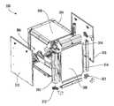
- FIG. 1is an isometric view of a frame for a telecommunications enclosure according to one example embodiment of this disclosure.
- FIG. 2is a telecommunications enclosure including the frame of FIG. 1 .
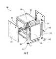
- FIG. 3is a partially exploded view of a telecommunications enclosure according to another example embodiment of this disclosure.
- FIG. 4is a top view of a frame member for a telecommunications enclosure according to another example embodiment of this disclosure.
- FIG. 5is an isometric view of the frame member of FIG. 4 .
- FIG. 6is a top view of a frame member including a gutter flange for a telecommunications enclosure according to another example embodiment of this disclosure.
- FIG. 7is an isometric view of the frame member of FIG. 6 .
- FIG. 8is a top view of a frame member including two gutter flanges for a telecommunications enclosure according to another example embodiment of this disclosure.
- FIG. 9is a top plan view of a frame member for a telecommunications enclosure according to another example embodiment of this disclosure with a portion of a panel coupled to an interior surface of the frame member.
- FIG. 10is an isometric view of a frame member for a telecommunications enclosure according to another example embodiment of this disclosure with a portion of two panels coupled to interior surfaces of the frame member.
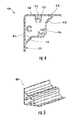
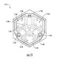
- FIG. 11is an isometric view of inner surfaces of a corner copula for a telecommunications enclosure according to another example embodiment of this disclosure.
- FIG. 12is an isometric view of outer surfaces of the corner copula of FIG. 11 .
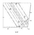
- FIG. 13is an exploded view of a portion of a telecommunications enclosure including a corner copula coupled to three frame members according to another example embodiment of this disclosure.
- FIG. 14is an isometric view of a portion of a telecommunications enclosure including a corner copula coupled to three frame members according to another example embodiment of this disclosure.
- FIG. 15is an isometric view of a portion of the telecommunications enclosure of FIG. 14 with a cover coupled to the corner copula.
- FIG. 16is an isometric view of a portion of a telecommunications enclosure according to another example embodiment of this disclosure including a corner copula with a lifting bracket mounted to auxiliary mounts of the corner copula.
- Example embodimentsare provided so that this disclosure will be thorough, and will fully convey the scope to those who are skilled in the art. Numerous specific details are set forth such as examples of specific components, devices, and methods, to provide a thorough understanding of embodiments of the present disclosure. It will be apparent to those skilled in the art that specific details need not be employed, that example embodiments may be embodied in many different forms and that neither should be construed to limit the scope of the disclosure. In some example embodiments, well-known processes, well-known device structures, and well-known technologies are not described in detail.
- first, second, third, etc.may be used herein to describe various elements, components, regions, layers and/or sections, these elements, components, regions, layers and/or sections should not be limited by these terms. These terms may be only used to distinguish one element, component, region, layer or section from another region, layer or section. Terms such as “first,” “second,” and other numerical terms when used herein do not imply a sequence or order unless clearly indicated by the context. Thus, a first element, component, region, layer or section discussed below could be termed a second element, component, region, layer or section without departing from the teachings of the example embodiments.
- Spatially relative termssuch as “inner,” “outer,” “beneath”, “below”, “lower”, “above”, “upper” and the like, may be used herein for ease of description to describe one element or feature's relationship to another element(s) or feature(s) as illustrated in the figures. Spatially relative terms may be intended to encompass different orientations of the device in use or operation in addition to the orientation depicted in the figures. For example, if the device in the figures is turned over, elements described as “below” or “beneath” other elements or features would then be oriented “above” the other elements or features. Thus, the example term “below” can encompass both an orientation of above and below. The device may be otherwise oriented (rotated 90 degrees or at other orientations) and the spatially relative descriptors used herein interpreted accordingly.
- FIGS. 1 and 2A telecommunications enclosure, generally indicated by reference numeral 100 , according to one aspect of the present disclosure is illustrated in FIGS. 1 and 2 .
- the enclosure 100includes a frame 102 .
- the frame 102includes a plurality of frame members 104 .
- the frame members 104define several openings 106 .
- Panels 108are attached to the frame members 104 and overlap, i.e. cover, the openings 106 .
- the frame members 104may be any suitable length to form an enclosure. Accordingly, a different size enclosure 100 may be constructed simply by using different lengths of frame members 104 .
- the frame members 104may also be cut to shorter length members from a longer frame member.
- the frame members 104may all have the same profile shape, or the enclosure may include frame members 104 with two or more different profiles, as desired.
- the frame members 104are connected together to form the frame 102 using several corner copulas 112 .
- Each corner copula 112(sometimes referred to as a corner connector) is connected to three frame members 104 .
- the corner copulas 112are connected to the frame members 104 using fasteners (e.g., screws, bolts, etc.).
- a rectangular or square shaped enclosure 100uses eight horizontal frame members 104 and four vertical frame members 104 . These twelve frame members are connected using eight corner copulas 112 .
- FIG. 3A partially exploded view of another example telecommunications 300 enclosure according to the present disclosure is illustrated in FIG. 3 .
- the enclosure 300includes a plurality of frame members 304 that define several openings 306 .
- the frame members 304are connected together by corner copulas 312 .
- Panels 308are attached to the frame members 304 and cover four of the openings 306 .
- Two of the openings 306are covered by doors 310 .
- the doors 310are attached to the frame members 304 and cover the two openings when closed. The doors 310 can be opened to access an interior of the assembled enclosure 300 .
- a gasketis positioned between a corner copula 112 , 312 and the frame member to which the corner copula 112 , 312 is attached. Accordingly, for the enclosure 300 , three gaskets are used with each corner copula 312 for a total of twenty-four corner gaskets. Further, the panels 108 , 308 attach to the frame members 104 , 304 from inside the frame of the enclosure 100 , 300 . A gasket channel in which a gasket is disposed is located on an interior surface of each frame member 104 , 304 .
- Retainers 314are attached to the frame members 104 , 304 to hold the panels 108 , 308 in place covering an opening in the enclosure 100 , 300 .
- the retainersalso bias the panels 108 , 308 against the gasket to create a seal around the opening 306 .
- FIGS. 4 through 8illustrate three example frame members 404 , 604 , 804 for use in a telecommunications enclosure as described above.
- FIGS. 4 and 5illustrate the frame member 404 .
- the frame member 604 in FIGS. 6 and 7is similar to the frame member 404 , but includes a protruding gutter flange 614 .
- the frame member 604is typically used to define an opening for a door in an enclosure. In an assembled telecommunication enclosure, the gutter flange 614 extends beyond the opening to provide additional protection against water, debris, etc. entering the enclosure.
- the frame member 804 in FIG. 8includes two protruding gutter flanges 814 .
- the frame member 804is typically used in an enclosure with an opening on both sides of the frame member 804 for which a gutter flange 814 is desired.
- the frame member 404has a generally triangular profile.
- the frame member 404is hollow and in some embodiments is formed by extrusion.
- Each frame member 404includes point guides 416 .
- the point guides 416help guide and align fasteners, e.g., self drilling screws, as the fastener are driven through a part of the frame member 404 .
- the frame member 404also includes thicker sections 418 located behind the point guides 416 for receiving fasteners driven into the frame member 404 at the locations of the point guides 416 .
- the frame member 404also includes a gasket channel 424 . As will be described in more detail below, a gasket may be positioned in the gasket channel 424 to seal an interface between a panel and the frame member 404 in a telecommunications enclosure.
- the frame members 404 , 604 , 804may be constructed of any suitable material.
- the frame members 404 , 604 , 804may be aluminum, steel, etc.
- the frame members 404 , 604 , 804may be made by any suitable process.
- the frame membersmay be extruded, cast, molded, machined, welded, or constructed using a combination of the foregoing techniques.
- panelsare used to cover openings in the frame of a telecommunications enclosure.
- the panelsare attached to the enclosure on an interior surface of the frame members of the enclosure.
- FIGS. 9 and 10One example is illustrated in FIGS. 9 and 10 .
- a panel 908is attached to a frame member 904 with a retainer 926 .
- the retainer 926is fastened to an interior portion of the frame member 904 with a fastener 928 .
- a gasket 930is positioned in the gasket channel 924 .
- the retainer 926applies a force against the panel 908 and toward the inner surface of the frame member 904 to hold the panel in position and bias the panel 908 against the gasket 930 . Accordingly, the interface between the panel 908 and the frame member 904 is substantially sealed.
- the retainer 926may be a discrete retainer as shown in FIGS. 9 and 10 .
- the retainermay also be incorporated (e.g. monolithically formed) into the panel 908 like the retainer 927 shown in FIG. 10 .
- the panels discussed abovemay be constructed from any suitable material or combination of materials.
- the panelscan be a single material, single layer composite, laminated material, etc.
- the panelsmay be steel, aluminum, wood, etc.
- the panelscan include insulation material (such as, for example extruded polystyrene) laminated between steel, aluminum or other materials.
- the panel materialscan be chosen to obtain various characteristics, such as, for example, EMI shielding, fire resistance, thermal insulation, electrical insulation, resistance to gunfire, capability of supporting equipment mounted to and/or integrated in/on the panel, etc.
- the corner copula 1112is generally shaped as three intersecting perpendicular sides of a cube.
- the corner copula 1112includes a first side 1130 , a second side 1132 , and a third side 1134 .
- Each side 1130 , 1132 , 1134includes an inner surface (one of the visible surfaces in FIG. 11 ) and an outer surface (one of the visible surfaces in FIG. 12 ).
- Each side 1130 , 1132 , 1134 of the corner copula 1112may be connected to a frame member 1104 , thus allowing the corner copula 1112 to connect three frame members 1104 .
- Each side 1130 , 1132 , 1134defines a plurality of fastener holes 1136 extending from the inner surface to the outer surface.
- Each fastener hole 1136can receive a fastener 1138 for coupling the corner copula 1112 to a frame member 1104 .
- each frame member 1104is connected to one side of a corner copula 1112 via three fasteners 1138 , (one through each fastener hole 1136 on such side). This evenly distributes the load on the corner copula 1112 and permits smaller fasteners 1138 to be used for connection between the frame members 1104 to the corner copula 1112 (as compared to using only one or two fasteners).
- a bridge portion 1140extends along part of the inner surfaces of the sides 1130 , 1132 , 1134 of the corner copula 1112 .
- the bridge portion 1140strengthens the corner copula 1112 and assists in distributing the load on the corner copula 1112 .
- the bridge portion 1140may be a unitary bridge portion, may be a plurality of bridge portions (such as separate bridge portions between each two perpendicular sides), etc. Further, the bridge portion 1140 may be monolithically formed with the corner copula 1112 , separately attached to the corner copula 1112 , or some combination of the two.
- the corner copula 1112includes three auxiliary mounts 1142 in the bridge portion 1140 .
- the auxiliary mounts 1142are adapted to receive auxiliary fasteners.
- the auxiliary mounts 1142may be used, for example, to attach an enclosure containing the corner copula 1112 to another enclosure or structure, etc.
- the auxiliary mounts 1142may also be used to attach auxiliary items to an enclosure containing the corner copula 1112 .
- the auxiliary mounts 1142can receive fasteners for attaching a cover (described below), a lifting bracket 1144 , etc.
- a cover 1146may be used with the corner copula 1112 (the corner copula 1112 and the cover 1146 sometimes referred to as a corner copula assembly).
- the cover 1146is illustrated attached to the corner copula 1112 in FIG. 15 .
- the cover 1146is substantially shaped as three intersecting perpendicular sides of a cube.
- the corner copula assemblyis shaped substantially as a cube.
- the cover 1146fits in a recess 1148 on the corner copula 1112 .
- the cover 1146may be attached to the corner copula 1112 by any suitable means, including, for example, by friction fit, using a snap fit, using one or more fasteners inserted into the auxiliary mounts 1142 , etc.
- the cover 1146covers the otherwise exposed fasteners of the corner copula 1112 . Accordingly, the cover 1146 may provide protection from environmental elements (such as rain, dust, debris, etc), limit unauthorized access to the fasteners 1138 , and provide a cleaner, more finished appearance.
- the outer surfaces of the corner copula 1112include several features for assembly and sealing of an enclosure including the corner copula 1112 .
- the outer surfaces of the corner copula 1112can best be seen in FIG. 12 .
- the corner copula 1112includes tabs 1148 protruding from the outer surface of the sides 1130 , 1132 , 1134 .
- the tabs 1148are adapted for engaging an adjacent frame member 1104 .
- the tabsassist in assembly and alignment between the corner copula 1112 and the frame members 1104 .
- a gasket 1150is positioned between the corner copula 1112 and a frame member 1104 to be attached to the corner copula 1112 (as best shown in FIG. 13 ).
- each compression stop 1152extends around a fastener hole 1136 .
- corner copulas and covers described abovemay be constructed of any suitable materials.
- the corner copulamay be metal, plastic, fiberglass, etc.
- the corner copulas and coversmay be fabricated by any suitable method, such as casting, molding, machining, stamping, etc. or a combination thereof.
- Telecommunications enclosures described abovemay be used in an interior or exterior location.
- the enclosuresmay house any suitable telecommunications equipment, such as, for example, switching equipment, batteries, wireless and wireline communication equipment, power supplies, etc.
Landscapes
- Engineering & Computer Science (AREA)
- Computer Networks & Wireless Communication (AREA)
- Microelectronics & Electronic Packaging (AREA)
- Health & Medical Sciences (AREA)
- Toxicology (AREA)
- Casings For Electric Apparatus (AREA)
- Patch Boards (AREA)
Abstract
Description
Claims (21)
Priority Applications (8)
| Application Number | Priority Date | Filing Date | Title |
|---|---|---|---|
| US12/552,045US8403431B2 (en) | 2009-09-01 | 2009-09-01 | Telecommunications enclosures |
| EP09849074.1AEP2474213B1 (en) | 2009-09-01 | 2009-09-25 | Telecommunications enclosures |
| MX2012002566AMX2012002566A (en) | 2009-09-01 | 2009-09-25 | Telecommunications enclosures. |
| CN200980161874.2ACN102754536B (en) | 2009-09-01 | 2009-09-25 | Telecom cabinet |
| CA2772276ACA2772276C (en) | 2009-09-01 | 2009-09-25 | Telecommunications enclosures |
| CN201510309145.4ACN104968174B (en) | 2009-09-01 | 2009-09-25 | Telecommunication cabinet |
| PCT/US2009/058415WO2011028211A1 (en) | 2009-09-01 | 2009-09-25 | Telecommunications enclosures |
| ZA2012/01439AZA201201439B (en) | 2009-09-01 | 2012-02-27 | Telecommunications enclosures |
Applications Claiming Priority (1)
| Application Number | Priority Date | Filing Date | Title |
|---|---|---|---|
| US12/552,045US8403431B2 (en) | 2009-09-01 | 2009-09-01 | Telecommunications enclosures |
Publications (2)
| Publication Number | Publication Date |
|---|---|
| US20110050052A1 US20110050052A1 (en) | 2011-03-03 |
| US8403431B2true US8403431B2 (en) | 2013-03-26 |
Family
ID=43623799
Family Applications (1)
| Application Number | Title | Priority Date | Filing Date |
|---|---|---|---|
| US12/552,045Active2030-04-19US8403431B2 (en) | 2009-09-01 | 2009-09-01 | Telecommunications enclosures |
Country Status (7)
| Country | Link |
|---|---|
| US (1) | US8403431B2 (en) |
| EP (1) | EP2474213B1 (en) |
| CN (2) | CN102754536B (en) |
| CA (1) | CA2772276C (en) |
| MX (1) | MX2012002566A (en) |
| WO (1) | WO2011028211A1 (en) |
| ZA (1) | ZA201201439B (en) |
Cited By (18)
| Publication number | Priority date | Publication date | Assignee | Title |
|---|---|---|---|---|
| US20120170972A1 (en)* | 2010-12-31 | 2012-07-05 | Song Xianmeng | Cabinet assembling apparatus and connecting pieces |
| US20130075056A1 (en)* | 2011-09-26 | 2013-03-28 | Futurewei Technologies, Inc. | Modular System and Framework for Supporting an Enclosure |
| US20130146321A1 (en)* | 2011-12-09 | 2013-06-13 | Trystar, Inc. | Portable power distribution box |
| US20140220288A1 (en)* | 2013-02-04 | 2014-08-07 | AIFO Group Zajac Ziecik Stabrawa Spolka jawna | Set of profiles for forming profile structures, complex profile, structure made of profiles and method for making structures using profiles |
| US20140294500A1 (en)* | 2011-02-25 | 2014-10-02 | C E S Control Enclosure Systems Gmbh | Corner connector for hollow profiles |
| US20150129527A1 (en)* | 2013-11-11 | 2015-05-14 | Atomic Energy Council - Institute Of Nuclear Energy Research | Frame structure of solar cell module |
| USD743908S1 (en) | 2014-12-03 | 2015-11-24 | Trystar, Inc. | Portable power distribution box |
| US20160192509A1 (en)* | 2013-08-12 | 2016-06-30 | Modaptix Limited | Modular Casings |
| US20160348958A1 (en)* | 2015-05-28 | 2016-12-01 | General Electric Company | Joint members for refrigerator appliance casings |
| US9549482B2 (en) | 2014-09-05 | 2017-01-17 | Emerson Network Power, Energy Systems, North America, Inc. | Cabinet frame enclosures, frame members and corresponding methods |
| US10045460B2 (en)* | 2014-09-02 | 2018-08-07 | Cp Cases Limited | Electronic rack and mounting chassis |
| US11064803B2 (en)* | 2019-05-13 | 2021-07-20 | The West Retail Group Limited | Kit of parts for a kitchen unit |
| US20210391697A1 (en)* | 2020-06-11 | 2021-12-16 | Abb Schweiz Ag | Fire Shield for Variable Frequency Drive Enclosure |
| US20220243747A1 (en)* | 2021-02-01 | 2022-08-04 | Schluter Systems, LP | Profile System for Intersecting Joints |
| US11412852B2 (en)* | 2018-04-17 | 2022-08-16 | G.S.Ace Industry Co., Ltd. | Planar exterior pipe rack system, and planar exterior forming square rack pipe and rack pipe connecting square joint which constitute planar exterior pipe rack system |
| US20230073519A1 (en)* | 2021-09-08 | 2023-03-09 | Vertiv Corporation | Electronic equipment enclosure with enhanced mounting flexibility |
| US20230347954A1 (en)* | 2022-05-02 | 2023-11-02 | Werner Co. | Utility cart |
| US12273663B2 (en) | 2022-09-07 | 2025-04-08 | Charles E WEAVER | Preconfigured weather-resistant enclosure assembly for terminating telecommunications equipment |
Families Citing this family (17)
| Publication number | Priority date | Publication date | Assignee | Title |
|---|---|---|---|---|
| US8365929B2 (en)* | 2009-06-10 | 2013-02-05 | Shenzhen Yeefu Precision Machinery Co., Ltd. | Cabinet frame for easy assembly |
| US20110089721A1 (en)* | 2009-10-15 | 2011-04-21 | Plastoform Blanca Ii D.O.O. | Module frame |
| DE102010034620A1 (en)* | 2010-08-17 | 2012-02-23 | Adc Gmbh | distribution cabinet |
| US8562084B2 (en)* | 2010-09-22 | 2013-10-22 | Emerson Network Power, Energy Systems, North America, Inc. | Enclosure corner seals and assemblies |
| US20130052726A1 (en)* | 2011-08-22 | 2013-02-28 | Lifetime Products, Inc. | Composter |
| TWM420105U (en)* | 2011-09-15 | 2012-01-01 | Taiwan Enclosure Systems Co Ltd | Assembled frame |
| US20130256251A1 (en)* | 2012-03-30 | 2013-10-03 | General Electric Company | Electrical system enclosures |
| US9393972B2 (en)* | 2012-05-09 | 2016-07-19 | Wabtec Holding Corp. | Modular support frame for railway vehicle equipment |
| EP2819254B1 (en)* | 2013-06-24 | 2018-08-08 | ABB S.p.A. | Frame assembly for a switchboard and related frame and switchboard |
| DE102014102465B4 (en)* | 2014-02-25 | 2022-08-18 | Rittal Gmbh & Co. Kg | switch cabinet |
| WO2016141493A1 (en)* | 2015-03-12 | 2016-09-15 | Storace Carmel Paul | Transport, storage and display case and system |
| KR101697965B1 (en)* | 2015-04-15 | 2017-01-20 | 주식회사 삼화에이스 | Insulation and minimizes leakage frame rate of the air conditioner |
| US10648497B2 (en)* | 2016-06-24 | 2020-05-12 | Mac Goelst | Connectable box carcass framework members |
| GB2559794A (en)* | 2017-02-20 | 2018-08-22 | Ge Aviat Systems Ltd | Avionics power management panel and door assembly |
| CN207219192U (en)* | 2017-06-05 | 2018-04-10 | 阳光电源股份有限公司 | Outdoor cabinet and its top structure |
| US10697699B2 (en)* | 2018-11-05 | 2020-06-30 | Whirlpool Corporation | Cabinet assembly of an appliance |
| EP3980826B1 (en) | 2019-06-07 | 2025-05-14 | Corning Research & Development Corporation | Sealing corner bracket for receiving two frame members and cabinet including corner bracket |
Citations (88)
| Publication number | Priority date | Publication date | Assignee | Title |
|---|---|---|---|---|
| US335592A (en)* | 1886-02-09 | Thomas keywoeth | ||
| US465609A (en)* | 1891-12-22 | William bunting | ||
| US822462A (en)* | 1905-11-29 | 1906-06-05 | Charles Martineau | Water-trap. |
| US1045389A (en)* | 1908-01-06 | 1912-11-26 | Horatio G Gillmor | Pipe-joint. |
| US1978019A (en)* | 1931-07-30 | 1934-10-23 | Goodrich Co B F | Pipe coupling and gasket therefor |
| US3044656A (en)* | 1959-08-24 | 1962-07-17 | Zero Mfg Company | Prefabricated shipping container |
| US3087768A (en)* | 1960-05-18 | 1963-04-30 | Amco Eng | Enclosure |
| US3380768A (en)* | 1964-11-02 | 1968-04-30 | Wolfensberger Paul | Profile rail and corner connecting piece |
| US3973854A (en)* | 1975-05-23 | 1976-08-10 | Armstrong Cork Company | Connectors for tubular framing members |
| US4045104A (en)* | 1975-08-20 | 1977-08-30 | Peterson Clinton B | Cabinet structure and method of construction |
| US4072432A (en)* | 1976-05-06 | 1978-02-07 | Capitol Hardware Manufacturing Company, Inc. | Connector for tubular frame members |
| US4082470A (en)* | 1976-03-12 | 1978-04-04 | Serbert Industries (Proprietary) Limited | Connector |
| US4101229A (en)* | 1976-02-19 | 1978-07-18 | Torsten Waloddi Weibull | Connection device |
| US4271654A (en)* | 1977-02-07 | 1981-06-09 | Otto Jungbluth | Three-dimensional structures of frame beams and multiple joints |
| US4468067A (en)* | 1982-08-11 | 1984-08-28 | Rock Leasing, Inc. | Display case with a hook locking mechanism |
| US4544069A (en)* | 1983-05-26 | 1985-10-01 | Gianfranco Cavallini | Modular elements for composing frames for the construction of cabinet structures and containers for electrical, electromechanical and electronic components, for internal and external use |
| US4643319A (en)* | 1983-12-09 | 1987-02-17 | Rittal-Werk Rudolf Loh Gmbh & Co. Kg | Framework for a switchboard cabinet |
| US4659869A (en)* | 1983-06-20 | 1987-04-21 | Pawling Rubber Corporation | Clip-on strip for RFT/EMI shielding |
| US4678359A (en)* | 1984-02-17 | 1987-07-07 | Egbert Keen | Device comprising a frame of lengths of tube and coupling pieces and coupling piece for the same |
| US4691970A (en)* | 1985-04-12 | 1987-09-08 | Armando Neri | Dustproof cabinet, in particular for electrical equipment |
| US4712695A (en)* | 1986-07-25 | 1987-12-15 | Cheng Huey Der | Structural frame connector |
| US4726701A (en) | 1986-06-19 | 1988-02-23 | Thomas Olivier A | Modular shelf assembly |
| US4768845A (en)* | 1986-11-03 | 1988-09-06 | Yeh Kuo Huei | Combination-type desk/cabinet compartment structure |
| US4869380A (en)* | 1986-09-26 | 1989-09-26 | Vormet Quality Fabrication Close/Corporation | Frame work |
| US4900108A (en)* | 1989-06-20 | 1990-02-13 | American Standard Inc. | Self-fixturing cabinet corner member |
| US4922669A (en)* | 1987-09-18 | 1990-05-08 | Quattrocchio S.R.L. | Modular latticework structure |
| US4997240A (en) | 1989-03-28 | 1991-03-05 | Siemens Aktiengesellschaft | Modular housing system for electronic equipment |
| US5020866A (en)* | 1989-11-13 | 1991-06-04 | Gichner Systems Group, Inc. | Enclosure for housing electronic components |
| US5147121A (en)* | 1989-11-13 | 1992-09-15 | Gichner Systems Group, Inc. | Gasket for providing EMI/RFI shielding |
| US5202818A (en)* | 1989-06-05 | 1993-04-13 | Merlin Gerin | Sealed switchgear cabinet |
| US5228762A (en)* | 1990-05-18 | 1993-07-20 | Transrack | Metal cabinet frame |
| US5315794A (en) | 1992-10-30 | 1994-05-31 | Professional Systems, Inc. | Enclosure for telecommunications equipment |
| US5388903A (en)* | 1991-11-27 | 1995-02-14 | Federal-Hoffman, Inc. | Multifaceted modular enclosure frame with integral sub-panel guide system |
| US5451115A (en)* | 1993-10-20 | 1995-09-19 | Sayres; David W. | Prefabricated corner joint for a framework comprising tubular members |
| US5513759A (en)* | 1993-09-28 | 1996-05-07 | Rittal-Werk Rudolf Loh Gmbh & Co. Kg | Rack frame |
| US5516225A (en) | 1994-05-04 | 1996-05-14 | Kvols; Kevin | Corner connector and molding therefor |
| US5548085A (en)* | 1994-11-21 | 1996-08-20 | Dsc Communications Corporation | Transportable weathertight and EMI shielded cabinet enclosure |
| US5574257A (en)* | 1992-10-15 | 1996-11-12 | Caschem, Inc. | Telecommunications articles containing gelled oil compositions |
| US5580181A (en)* | 1994-10-31 | 1996-12-03 | Nic Autotec, Inc. | Cubic connector structure for connecting frame bars and method of producing same |
| US5584406A (en)* | 1993-09-28 | 1996-12-17 | Rittal-Werk Rudolf Loh Gmbh & Co. Kg | Rack frame |
| US5651630A (en)* | 1994-12-07 | 1997-07-29 | Nomura; Ryoichi | Connecting devices for frame bars with polygonal cross-sectional shape |
| US5678375A (en)* | 1992-07-07 | 1997-10-21 | Juola; Tuomo | Framework of a building |
| US5713651A (en) | 1996-02-27 | 1998-02-03 | Mcquay International | Modular frame assembly for an equipment cabinet |
| US5749476A (en)* | 1993-10-23 | 1998-05-12 | Rittal-Werk Rudolf Loh Gmbh & Co. Kg | Rack for a switching cabinet |
| US5806946A (en)* | 1994-11-05 | 1998-09-15 | Rittal-Werk Rudolf Loh Gmbh & Co. Kg | Switchgear cabinet with frame |
| US5820289A (en)* | 1995-08-09 | 1998-10-13 | Schroff Gmbh | Corner joint element |
| US5921052A (en)* | 1993-12-03 | 1999-07-13 | Specialized Banking Furniture (International), Inc. | Trader desk frame |
| US5932843A (en)* | 1995-02-27 | 1999-08-03 | Rittal-Werk Rudolf Loh Gmbh & Co., Kg | Switchgear cabinet with a frame and door elements |
| US5997117A (en)* | 1997-06-06 | 1999-12-07 | Chatsworth Products, Inc. | Rack frame cabinet |
| US6039420A (en) | 1994-11-05 | 2000-03-21 | Rittal-Werk Rudolf Loh Gmbh & Co. Kg | Frame for a switchgear cabinet |
| US6042202A (en)* | 1997-06-06 | 2000-03-28 | Goppion S.R.L. | Sealed showcase |
| US6062664A (en)* | 1994-11-05 | 2000-05-16 | Rittal-Werk Rudolf Loh Gmbh & Co., Kg | Frame for a switchgear cabinet |
| US6102498A (en)* | 1996-11-19 | 2000-08-15 | Rittal-Werk Rudolf Loh Gmbh & Co. Kg | Rack for a switching cabinet |
| US6123400A (en)* | 1996-11-19 | 2000-09-26 | Rittal-Werk Rudolf Loh Gmbh & Co. Kg | Switching cabinet |
| US6142594A (en)* | 1996-11-19 | 2000-11-07 | Rittal-Werk Rudolf Loh Gmbh & Co. Kg | Rack with a lower frame and an upper frame made of a continuous section |
| US6149255A (en)* | 1996-11-19 | 2000-11-21 | Rittal-Werk Rudolf Loh Gmbh & Co. Kg | Corner connector for a rack |
| US6164737A (en)* | 1996-11-19 | 2000-12-26 | Rittal-Werk Rudolf Loh Gmbh & Co. Kg | Switching cabinet with a rack |
| US6179398B1 (en)* | 1999-01-29 | 2001-01-30 | Michael Alan Martin | Corner piece and cabinet frame |
| US6231142B1 (en)* | 1998-11-20 | 2001-05-15 | Hans Skeppner | Switch cabinet |
| US6238027B1 (en)* | 1998-04-18 | 2001-05-29 | Rittal-Werk Rudolf Loh Gmbh & Co. Kg | Switching cabinet |
| US6303854B1 (en)* | 1999-07-22 | 2001-10-16 | Marconi Communications, Inc. | EMI shielded telecommunications enclosure |
| US6315132B1 (en) | 1999-07-10 | 2001-11-13 | Rittal-Werk Rudolf Loh Gmbh & Co. Kg | Rack for a switchgear cabinet |
| US6347489B1 (en) | 1998-05-01 | 2002-02-19 | Chester R. Marshall, Jr. | Storm anchor system including foundation column with adjustable saddle-type positioning members |
| US20020043388A1 (en)* | 2000-03-15 | 2002-04-18 | Martin Ramdohr | Switchgear cabinet |
| US6400567B1 (en)* | 2000-10-19 | 2002-06-04 | Fujitsu Network Communications, Inc. | Equipment enclosure having separate compartments cooled by separate cooling airflows |
| US6428127B1 (en)* | 1998-04-27 | 2002-08-06 | Knud Rasmussen | Cabinet frame |
| US20020121387A1 (en)* | 2001-03-01 | 2002-09-05 | Nitto Electric Works, Ltd. | Frame for electrical and electronic equipment housing cabinets and a frame joining structure |
| US20030020382A1 (en)* | 2001-07-13 | 2003-01-30 | Herbeck Christian C. | Panel seal for an air handling unit |
| US6533373B2 (en)* | 2000-02-17 | 2003-03-18 | Rittal Rudolf Loh Gmbh & Co. Kg | Cable conduit for a switchgear cabinet with a rack |
| US6634512B2 (en)* | 2000-05-04 | 2003-10-21 | Knuerr-Mechanik Fuer Die Elektronik Aktiengesellschaft | Basic rack |
| US6776665B2 (en) | 2002-11-25 | 2004-08-17 | George Ying-Liang Huang | Electrical connector with a transparent insulating jacket |
| US6791027B1 (en)* | 1998-03-18 | 2004-09-14 | Rittal Gmbh & Co. Kg | Component kit for a switch cabinet |
| US6792732B2 (en)* | 2000-01-05 | 2004-09-21 | Syma Intercontinental Ag | Cube-shaped profile element and profile strip therefor |
| US6808240B2 (en)* | 2001-07-27 | 2004-10-26 | Ise Innomotive Systems Europe Gmbh | Switch cabinet frame structure |
| US20040235319A1 (en) | 1998-10-26 | 2004-11-25 | Shozo Shimada | Telecommunications device |
| US6854238B2 (en)* | 2002-11-12 | 2005-02-15 | Alfred Boots | Structural connection system for frameworks |
| US6871902B2 (en) | 1998-11-04 | 2005-03-29 | Transit Care, Inc. | Quick release sacrificial shield and window assembly |
| US6915616B2 (en)* | 2002-03-06 | 2005-07-12 | Abb Service S.R.L. | Frame member for electrical distribution cabinets |
| US6962262B2 (en)* | 2003-02-10 | 2005-11-08 | Dennis Toma | Connecting corner for knock down racks |
| WO2006022600A1 (en) | 2004-08-23 | 2006-03-02 | Canovate Elektronik Endustri Ve Ticaret A.S. | A bearing frame for equipment cabinet racks |
| US7188570B2 (en)* | 2005-03-08 | 2007-03-13 | Middle Atlantic Products, Inc. | Electrical equipment enclosure |
| US7316461B2 (en)* | 2002-05-23 | 2008-01-08 | Viasystems Group, Inc. | Indoor-outdoor equipment enclosure and method for assembling the same |
| US7322770B2 (en)* | 2000-09-28 | 2008-01-29 | Manfred Frank Patent Holdings Limited | Joint arrangement for demountable structure |
| US7427713B2 (en)* | 2006-03-13 | 2008-09-23 | Panduit Corp. | Network cabinet |
| US7441847B2 (en)* | 2002-06-06 | 2008-10-28 | Melquisedec Francisquini | Metallic profile for the composition of structures for the assembly of cabinet/enclosures |
| US7683270B2 (en)* | 2005-06-03 | 2010-03-23 | Telect Inc. | Telecommunications cabinet |
| US7896177B1 (en)* | 2008-05-08 | 2011-03-01 | Toma Dennis R | Versatile support system and methods thereof |
| US7926241B2 (en) | 2006-12-04 | 2011-04-19 | Composite Panel Systems, Llc | Building panels |
Family Cites Families (5)
| Publication number | Priority date | Publication date | Assignee | Title |
|---|---|---|---|---|
| DE9413840U1 (en)* | 1994-08-26 | 1995-10-12 | Julius & August Erbslöh GmbH & Co, 42553 Velbert | Corner connection for profiles forming a framework |
| US5678357A (en)* | 1996-03-20 | 1997-10-21 | Rubio; Jesse | Interactive inflatable toy |
| CN2556549Y (en)* | 2002-06-07 | 2003-06-18 | 深圳麦克维尔空调有限公司 | Air conditioning cabinet with double-layer panel |
| US20060076858A1 (en)* | 2004-10-11 | 2006-04-13 | Victor Nohl | Modular enclosure system |
| EP2091388A1 (en)* | 2006-12-07 | 2009-08-26 | Knürr AG | Cabinet body, in particular for outdoor cabinets, and method of producing a cabinet body |
- 2009
- 2009-09-01USUS12/552,045patent/US8403431B2/enactiveActive
- 2009-09-25WOPCT/US2009/058415patent/WO2011028211A1/enactiveApplication Filing
- 2009-09-25MXMX2012002566Apatent/MX2012002566A/enactiveIP Right Grant
- 2009-09-25CNCN200980161874.2Apatent/CN102754536B/enactiveActive
- 2009-09-25EPEP09849074.1Apatent/EP2474213B1/enactiveActive
- 2009-09-25CNCN201510309145.4Apatent/CN104968174B/enactiveActive
- 2009-09-25CACA2772276Apatent/CA2772276C/enactiveActive
- 2012
- 2012-02-27ZAZA2012/01439Apatent/ZA201201439B/enunknown
Patent Citations (89)
| Publication number | Priority date | Publication date | Assignee | Title |
|---|---|---|---|---|
| US465609A (en)* | 1891-12-22 | William bunting | ||
| US335592A (en)* | 1886-02-09 | Thomas keywoeth | ||
| US822462A (en)* | 1905-11-29 | 1906-06-05 | Charles Martineau | Water-trap. |
| US1045389A (en)* | 1908-01-06 | 1912-11-26 | Horatio G Gillmor | Pipe-joint. |
| US1978019A (en)* | 1931-07-30 | 1934-10-23 | Goodrich Co B F | Pipe coupling and gasket therefor |
| US3044656A (en)* | 1959-08-24 | 1962-07-17 | Zero Mfg Company | Prefabricated shipping container |
| US3087768A (en)* | 1960-05-18 | 1963-04-30 | Amco Eng | Enclosure |
| US3380768A (en)* | 1964-11-02 | 1968-04-30 | Wolfensberger Paul | Profile rail and corner connecting piece |
| US3973854A (en)* | 1975-05-23 | 1976-08-10 | Armstrong Cork Company | Connectors for tubular framing members |
| US4045104A (en)* | 1975-08-20 | 1977-08-30 | Peterson Clinton B | Cabinet structure and method of construction |
| US4101229A (en)* | 1976-02-19 | 1978-07-18 | Torsten Waloddi Weibull | Connection device |
| US4082470A (en)* | 1976-03-12 | 1978-04-04 | Serbert Industries (Proprietary) Limited | Connector |
| US4072432A (en)* | 1976-05-06 | 1978-02-07 | Capitol Hardware Manufacturing Company, Inc. | Connector for tubular frame members |
| US4271654A (en)* | 1977-02-07 | 1981-06-09 | Otto Jungbluth | Three-dimensional structures of frame beams and multiple joints |
| US4468067A (en)* | 1982-08-11 | 1984-08-28 | Rock Leasing, Inc. | Display case with a hook locking mechanism |
| US4544069A (en)* | 1983-05-26 | 1985-10-01 | Gianfranco Cavallini | Modular elements for composing frames for the construction of cabinet structures and containers for electrical, electromechanical and electronic components, for internal and external use |
| US4659869A (en)* | 1983-06-20 | 1987-04-21 | Pawling Rubber Corporation | Clip-on strip for RFT/EMI shielding |
| US4643319A (en)* | 1983-12-09 | 1987-02-17 | Rittal-Werk Rudolf Loh Gmbh & Co. Kg | Framework for a switchboard cabinet |
| US4678359A (en)* | 1984-02-17 | 1987-07-07 | Egbert Keen | Device comprising a frame of lengths of tube and coupling pieces and coupling piece for the same |
| US4691970A (en)* | 1985-04-12 | 1987-09-08 | Armando Neri | Dustproof cabinet, in particular for electrical equipment |
| US4726701A (en) | 1986-06-19 | 1988-02-23 | Thomas Olivier A | Modular shelf assembly |
| US4712695A (en)* | 1986-07-25 | 1987-12-15 | Cheng Huey Der | Structural frame connector |
| US4869380A (en)* | 1986-09-26 | 1989-09-26 | Vormet Quality Fabrication Close/Corporation | Frame work |
| US4768845A (en)* | 1986-11-03 | 1988-09-06 | Yeh Kuo Huei | Combination-type desk/cabinet compartment structure |
| US4922669A (en)* | 1987-09-18 | 1990-05-08 | Quattrocchio S.R.L. | Modular latticework structure |
| US4997240A (en) | 1989-03-28 | 1991-03-05 | Siemens Aktiengesellschaft | Modular housing system for electronic equipment |
| US5202818A (en)* | 1989-06-05 | 1993-04-13 | Merlin Gerin | Sealed switchgear cabinet |
| US4900108A (en)* | 1989-06-20 | 1990-02-13 | American Standard Inc. | Self-fixturing cabinet corner member |
| US5020866A (en)* | 1989-11-13 | 1991-06-04 | Gichner Systems Group, Inc. | Enclosure for housing electronic components |
| US5147121A (en)* | 1989-11-13 | 1992-09-15 | Gichner Systems Group, Inc. | Gasket for providing EMI/RFI shielding |
| US5228762A (en)* | 1990-05-18 | 1993-07-20 | Transrack | Metal cabinet frame |
| US5388903A (en)* | 1991-11-27 | 1995-02-14 | Federal-Hoffman, Inc. | Multifaceted modular enclosure frame with integral sub-panel guide system |
| US5678375A (en)* | 1992-07-07 | 1997-10-21 | Juola; Tuomo | Framework of a building |
| US5574257A (en)* | 1992-10-15 | 1996-11-12 | Caschem, Inc. | Telecommunications articles containing gelled oil compositions |
| US5315794A (en) | 1992-10-30 | 1994-05-31 | Professional Systems, Inc. | Enclosure for telecommunications equipment |
| US5513759A (en)* | 1993-09-28 | 1996-05-07 | Rittal-Werk Rudolf Loh Gmbh & Co. Kg | Rack frame |
| US5584406A (en)* | 1993-09-28 | 1996-12-17 | Rittal-Werk Rudolf Loh Gmbh & Co. Kg | Rack frame |
| US5451115A (en)* | 1993-10-20 | 1995-09-19 | Sayres; David W. | Prefabricated corner joint for a framework comprising tubular members |
| US5749476A (en)* | 1993-10-23 | 1998-05-12 | Rittal-Werk Rudolf Loh Gmbh & Co. Kg | Rack for a switching cabinet |
| US5921052A (en)* | 1993-12-03 | 1999-07-13 | Specialized Banking Furniture (International), Inc. | Trader desk frame |
| US5516225A (en) | 1994-05-04 | 1996-05-14 | Kvols; Kevin | Corner connector and molding therefor |
| US5580181A (en)* | 1994-10-31 | 1996-12-03 | Nic Autotec, Inc. | Cubic connector structure for connecting frame bars and method of producing same |
| US5806946A (en)* | 1994-11-05 | 1998-09-15 | Rittal-Werk Rudolf Loh Gmbh & Co. Kg | Switchgear cabinet with frame |
| US6039420A (en) | 1994-11-05 | 2000-03-21 | Rittal-Werk Rudolf Loh Gmbh & Co. Kg | Frame for a switchgear cabinet |
| US6062664A (en)* | 1994-11-05 | 2000-05-16 | Rittal-Werk Rudolf Loh Gmbh & Co., Kg | Frame for a switchgear cabinet |
| US5548085A (en)* | 1994-11-21 | 1996-08-20 | Dsc Communications Corporation | Transportable weathertight and EMI shielded cabinet enclosure |
| US5651630A (en)* | 1994-12-07 | 1997-07-29 | Nomura; Ryoichi | Connecting devices for frame bars with polygonal cross-sectional shape |
| US5932843A (en)* | 1995-02-27 | 1999-08-03 | Rittal-Werk Rudolf Loh Gmbh & Co., Kg | Switchgear cabinet with a frame and door elements |
| US5820289A (en)* | 1995-08-09 | 1998-10-13 | Schroff Gmbh | Corner joint element |
| US5713651A (en) | 1996-02-27 | 1998-02-03 | Mcquay International | Modular frame assembly for an equipment cabinet |
| US6102498A (en)* | 1996-11-19 | 2000-08-15 | Rittal-Werk Rudolf Loh Gmbh & Co. Kg | Rack for a switching cabinet |
| US6123400A (en)* | 1996-11-19 | 2000-09-26 | Rittal-Werk Rudolf Loh Gmbh & Co. Kg | Switching cabinet |
| US6142594A (en)* | 1996-11-19 | 2000-11-07 | Rittal-Werk Rudolf Loh Gmbh & Co. Kg | Rack with a lower frame and an upper frame made of a continuous section |
| US6149255A (en)* | 1996-11-19 | 2000-11-21 | Rittal-Werk Rudolf Loh Gmbh & Co. Kg | Corner connector for a rack |
| US6164737A (en)* | 1996-11-19 | 2000-12-26 | Rittal-Werk Rudolf Loh Gmbh & Co. Kg | Switching cabinet with a rack |
| US5997117A (en)* | 1997-06-06 | 1999-12-07 | Chatsworth Products, Inc. | Rack frame cabinet |
| US6042202A (en)* | 1997-06-06 | 2000-03-28 | Goppion S.R.L. | Sealed showcase |
| US6791027B1 (en)* | 1998-03-18 | 2004-09-14 | Rittal Gmbh & Co. Kg | Component kit for a switch cabinet |
| US6238027B1 (en)* | 1998-04-18 | 2001-05-29 | Rittal-Werk Rudolf Loh Gmbh & Co. Kg | Switching cabinet |
| US6428127B1 (en)* | 1998-04-27 | 2002-08-06 | Knud Rasmussen | Cabinet frame |
| US6347489B1 (en) | 1998-05-01 | 2002-02-19 | Chester R. Marshall, Jr. | Storm anchor system including foundation column with adjustable saddle-type positioning members |
| US20040235319A1 (en) | 1998-10-26 | 2004-11-25 | Shozo Shimada | Telecommunications device |
| US6871902B2 (en) | 1998-11-04 | 2005-03-29 | Transit Care, Inc. | Quick release sacrificial shield and window assembly |
| US6231142B1 (en)* | 1998-11-20 | 2001-05-15 | Hans Skeppner | Switch cabinet |
| US6179398B1 (en)* | 1999-01-29 | 2001-01-30 | Michael Alan Martin | Corner piece and cabinet frame |
| US6315132B1 (en) | 1999-07-10 | 2001-11-13 | Rittal-Werk Rudolf Loh Gmbh & Co. Kg | Rack for a switchgear cabinet |
| US6303854B1 (en)* | 1999-07-22 | 2001-10-16 | Marconi Communications, Inc. | EMI shielded telecommunications enclosure |
| US6792732B2 (en)* | 2000-01-05 | 2004-09-21 | Syma Intercontinental Ag | Cube-shaped profile element and profile strip therefor |
| US6533373B2 (en)* | 2000-02-17 | 2003-03-18 | Rittal Rudolf Loh Gmbh & Co. Kg | Cable conduit for a switchgear cabinet with a rack |
| US20020043388A1 (en)* | 2000-03-15 | 2002-04-18 | Martin Ramdohr | Switchgear cabinet |
| US6634512B2 (en)* | 2000-05-04 | 2003-10-21 | Knuerr-Mechanik Fuer Die Elektronik Aktiengesellschaft | Basic rack |
| US7322770B2 (en)* | 2000-09-28 | 2008-01-29 | Manfred Frank Patent Holdings Limited | Joint arrangement for demountable structure |
| US6400567B1 (en)* | 2000-10-19 | 2002-06-04 | Fujitsu Network Communications, Inc. | Equipment enclosure having separate compartments cooled by separate cooling airflows |
| US20020121387A1 (en)* | 2001-03-01 | 2002-09-05 | Nitto Electric Works, Ltd. | Frame for electrical and electronic equipment housing cabinets and a frame joining structure |
| US6965075B2 (en)* | 2001-03-01 | 2005-11-15 | Nitto Electric Works, Ltd. | Frame for electrical and electronic equipment housing cabinets and a frame joining structure |
| US20030020382A1 (en)* | 2001-07-13 | 2003-01-30 | Herbeck Christian C. | Panel seal for an air handling unit |
| US6808240B2 (en)* | 2001-07-27 | 2004-10-26 | Ise Innomotive Systems Europe Gmbh | Switch cabinet frame structure |
| US6915616B2 (en)* | 2002-03-06 | 2005-07-12 | Abb Service S.R.L. | Frame member for electrical distribution cabinets |
| US7316461B2 (en)* | 2002-05-23 | 2008-01-08 | Viasystems Group, Inc. | Indoor-outdoor equipment enclosure and method for assembling the same |
| US7441847B2 (en)* | 2002-06-06 | 2008-10-28 | Melquisedec Francisquini | Metallic profile for the composition of structures for the assembly of cabinet/enclosures |
| US6854238B2 (en)* | 2002-11-12 | 2005-02-15 | Alfred Boots | Structural connection system for frameworks |
| US6776665B2 (en) | 2002-11-25 | 2004-08-17 | George Ying-Liang Huang | Electrical connector with a transparent insulating jacket |
| US6962262B2 (en)* | 2003-02-10 | 2005-11-08 | Dennis Toma | Connecting corner for knock down racks |
| WO2006022600A1 (en) | 2004-08-23 | 2006-03-02 | Canovate Elektronik Endustri Ve Ticaret A.S. | A bearing frame for equipment cabinet racks |
| US7188570B2 (en)* | 2005-03-08 | 2007-03-13 | Middle Atlantic Products, Inc. | Electrical equipment enclosure |
| US7683270B2 (en)* | 2005-06-03 | 2010-03-23 | Telect Inc. | Telecommunications cabinet |
| US7427713B2 (en)* | 2006-03-13 | 2008-09-23 | Panduit Corp. | Network cabinet |
| US7926241B2 (en) | 2006-12-04 | 2011-04-19 | Composite Panel Systems, Llc | Building panels |
| US7896177B1 (en)* | 2008-05-08 | 2011-03-01 | Toma Dennis R | Versatile support system and methods thereof |
Cited By (30)
| Publication number | Priority date | Publication date | Assignee | Title |
|---|---|---|---|---|
| US20120170972A1 (en)* | 2010-12-31 | 2012-07-05 | Song Xianmeng | Cabinet assembling apparatus and connecting pieces |
| US9371849B2 (en)* | 2011-02-25 | 2016-06-21 | C E S Control Enclosure Systems Gmbh | Corner connector for hollow profiles |
| US20140294500A1 (en)* | 2011-02-25 | 2014-10-02 | C E S Control Enclosure Systems Gmbh | Corner connector for hollow profiles |
| US8599540B2 (en)* | 2011-09-26 | 2013-12-03 | Futurewei Technologies, Inc. | Modular system and framework for supporting an enclosure |
| US20130075056A1 (en)* | 2011-09-26 | 2013-03-28 | Futurewei Technologies, Inc. | Modular System and Framework for Supporting an Enclosure |
| US8616661B2 (en)* | 2011-12-09 | 2013-12-31 | Trystar, Inc. | Portable power distribution box |
| US20130146321A1 (en)* | 2011-12-09 | 2013-06-13 | Trystar, Inc. | Portable power distribution box |
| US20140220288A1 (en)* | 2013-02-04 | 2014-08-07 | AIFO Group Zajac Ziecik Stabrawa Spolka jawna | Set of profiles for forming profile structures, complex profile, structure made of profiles and method for making structures using profiles |
| US8998526B2 (en)* | 2013-02-04 | 2015-04-07 | AIFO Group Zajac Ziecik Stabrawa Spolka jawna | Structural profile system |
| US20160192509A1 (en)* | 2013-08-12 | 2016-06-30 | Modaptix Limited | Modular Casings |
| US9763338B2 (en)* | 2013-08-12 | 2017-09-12 | Modaptix Limited | Modular casings |
| US20150129527A1 (en)* | 2013-11-11 | 2015-05-14 | Atomic Energy Council - Institute Of Nuclear Energy Research | Frame structure of solar cell module |
| US10045460B2 (en)* | 2014-09-02 | 2018-08-07 | Cp Cases Limited | Electronic rack and mounting chassis |
| US9578772B2 (en) | 2014-09-05 | 2017-02-21 | Emerson Network Power, Energy Systems, North America, Inc. | Cabinet frame enclosures, frame members and corresponding methods |
| US9596778B2 (en) | 2014-09-05 | 2017-03-14 | Emerson Network Power, Energy Systems, North America, Inc. | Cabinet frame enclosures, frame members and corresponding methods |
| US9622369B2 (en) | 2014-09-05 | 2017-04-11 | Emerson Network Power, Energy Systems, North America, Inc. | Cabinet frame enclosures, frame members and corresponding methods |
| US9549482B2 (en) | 2014-09-05 | 2017-01-17 | Emerson Network Power, Energy Systems, North America, Inc. | Cabinet frame enclosures, frame members and corresponding methods |
| USD743908S1 (en) | 2014-12-03 | 2015-11-24 | Trystar, Inc. | Portable power distribution box |
| US20160348958A1 (en)* | 2015-05-28 | 2016-12-01 | General Electric Company | Joint members for refrigerator appliance casings |
| US9810474B2 (en)* | 2015-05-28 | 2017-11-07 | Haier Us Appliance Solutions, Inc. | Joint members for refrigerator appliance casings |
| US11412852B2 (en)* | 2018-04-17 | 2022-08-16 | G.S.Ace Industry Co., Ltd. | Planar exterior pipe rack system, and planar exterior forming square rack pipe and rack pipe connecting square joint which constitute planar exterior pipe rack system |
| US11064803B2 (en)* | 2019-05-13 | 2021-07-20 | The West Retail Group Limited | Kit of parts for a kitchen unit |
| US11665849B2 (en)* | 2020-06-11 | 2023-05-30 | Abb Schweiz Ag | Fire shield for variable frequency drive enclosure |
| US20210391697A1 (en)* | 2020-06-11 | 2021-12-16 | Abb Schweiz Ag | Fire Shield for Variable Frequency Drive Enclosure |
| US20220243747A1 (en)* | 2021-02-01 | 2022-08-04 | Schluter Systems, LP | Profile System for Intersecting Joints |
| US12180987B2 (en)* | 2021-02-01 | 2024-12-31 | Schluter Systems L.P. | Profile system for intersecting joints |
| US20230073519A1 (en)* | 2021-09-08 | 2023-03-09 | Vertiv Corporation | Electronic equipment enclosure with enhanced mounting flexibility |
| US12302527B2 (en)* | 2021-09-08 | 2025-05-13 | Vertiv Corporation | Electronic equipment enclosure with enhanced mounting flexibility |
| US20230347954A1 (en)* | 2022-05-02 | 2023-11-02 | Werner Co. | Utility cart |
| US12273663B2 (en) | 2022-09-07 | 2025-04-08 | Charles E WEAVER | Preconfigured weather-resistant enclosure assembly for terminating telecommunications equipment |
Also Published As
| Publication number | Publication date |
|---|---|
| WO2011028211A1 (en) | 2011-03-10 |
| CN102754536B (en) | 2015-07-08 |
| EP2474213B1 (en) | 2016-09-21 |
| CA2772276A1 (en) | 2011-03-10 |
| ZA201201439B (en) | 2013-05-29 |
| MX2012002566A (en) | 2012-07-23 |
| CN104968174A (en) | 2015-10-07 |
| EP2474213A4 (en) | 2014-03-12 |
| US20110050052A1 (en) | 2011-03-03 |
| CN104968174B (en) | 2018-07-03 |
| CA2772276C (en) | 2016-07-26 |
| CN102754536A (en) | 2012-10-24 |
| EP2474213A1 (en) | 2012-07-11 |
Similar Documents
| Publication | Publication Date | Title |
|---|---|---|
| US8403431B2 (en) | Telecommunications enclosures | |
| US8562084B2 (en) | Enclosure corner seals and assemblies | |
| US9578772B2 (en) | Cabinet frame enclosures, frame members and corresponding methods | |
| US8141965B2 (en) | L-shaped door with three-surface seal for endplates | |
| US20060180332A1 (en) | Recessed floor box cover assembly | |
| US6843543B2 (en) | Weatherproof enclosure with a modular structure | |
| US8555591B2 (en) | Outdoor enclosure louver system | |
| US20150097471A1 (en) | Water resistant outdoor electronics cabinet | |
| JP4715789B2 (en) | Rainproof cover | |
| AU2009251099B2 (en) | Weatherproof Double Door Sealing Arrangement | |
| AU2009251100B2 (en) | Weatherproof Frame Sealing Arrangement | |
| KR102179400B1 (en) | Wall corner connectors for panel prefabricated structures | |
| JP2018096064A (en) | Assembly structure of waterproof panel | |
| US20020063498A1 (en) | Seamless slide plate for outdoor enclosure | |
| JP4142710B2 (en) | Cover means | |
| US20240084961A1 (en) | Solid siding mounting block | |
| JP2002227531A (en) | Door fitting structure of prefabricated shed | |
| US11220165B2 (en) | Compartment sealing system | |
| KR102146335B1 (en) | Wall connectors for panel prefabricated structures | |
| US20230120027A1 (en) | Metal enclosure for electrical components | |
| JP2005168078A (en) | Cubicle protective cover |
Legal Events
| Date | Code | Title | Description |
|---|---|---|---|
| AS | Assignment | Owner name:EMERSON NETWORK POWER, ENERGY SYSTEMS, NORTH AMERI Free format text:ASSIGNMENT OF ASSIGNORS INTEREST;ASSIGNORS:ELKINS, JIN;WHITESIDE, CHRISTOPHER S.;NILSSON, HANS BERTIL;SIGNING DATES FROM 20091104 TO 20091111;REEL/FRAME:023924/0483 | |
| STCF | Information on status: patent grant | Free format text:PATENTED CASE | |
| FPAY | Fee payment | Year of fee payment:4 | |
| AS | Assignment | Owner name:JPMORGAN CHASE BANK, N.A., AS COLLATERAL AGENT, NE Free format text:SECURITY AGREEMENT;ASSIGNORS:ALBER CORP.;ASCO POWER TECHNOLOGIES, L.P.;AVOCENT CORPORATION;AND OTHERS;REEL/FRAME:040783/0148 Effective date:20161130 Owner name:JPMORGAN CHASE BANK, N.A., AS COLLATERAL AGENT, NEW YORK Free format text:SECURITY AGREEMENT;ASSIGNORS:ALBER CORP.;ASCO POWER TECHNOLOGIES, L.P.;AVOCENT CORPORATION;AND OTHERS;REEL/FRAME:040783/0148 Effective date:20161130 | |
| AS | Assignment | Owner name:JPMORGAN CHASE BANK, N.A., AS COLLATERAL AGENT, NE Free format text:SECURITY AGREEMENT;ASSIGNORS:ALBER CORP.;ASCO POWER TECHNOLOGIES, L.P.;AVOCENT CORPORATION;AND OTHERS;REEL/FRAME:040797/0615 Effective date:20161130 Owner name:JPMORGAN CHASE BANK, N.A., AS COLLATERAL AGENT, NEW YORK Free format text:SECURITY AGREEMENT;ASSIGNORS:ALBER CORP.;ASCO POWER TECHNOLOGIES, L.P.;AVOCENT CORPORATION;AND OTHERS;REEL/FRAME:040797/0615 Effective date:20161130 | |
| AS | Assignment | Owner name:VERTIV ENERGY SYSTEMS, INC., ILLINOIS Free format text:CHANGE OF NAME;ASSIGNOR:EMERSON NETWORK POWER, ENERGY SYSTEMS, NORTH AMERICA, INC.;REEL/FRAME:042469/0671 Effective date:20170403 | |
| AS | Assignment | Owner name:THE BANK OF NEW YORK MELLON TRUST COMPANY, N.A., T Free format text:SECOND LIEN SECURITY AGREEMENT;ASSIGNORS:VERTIV IT SYSTEMS, INC.;VERTIV CORPORATION;VERTIV NORTH AMERICA, INC.;AND OTHERS;REEL/FRAME:049415/0262 Effective date:20190513 Owner name:THE BANK OF NEW YORK MELLON TRUST COMPANY, N.A., TEXAS Free format text:SECOND LIEN SECURITY AGREEMENT;ASSIGNORS:VERTIV IT SYSTEMS, INC.;VERTIV CORPORATION;VERTIV NORTH AMERICA, INC.;AND OTHERS;REEL/FRAME:049415/0262 Effective date:20190513 | |
| AS | Assignment | Owner name:VERTIV CORPORATION, OHIO Free format text:MERGER;ASSIGNOR:VERTIV ENERGY SYSTEMS, INC.;REEL/FRAME:051830/0692 Effective date:20191231 | |
| AS | Assignment | Owner name:VERTIV CORPORATION (F/K/A EMERSON NETWORK POWER, ENERGY SYSTEMS, NORTH AMERICA, INC.), OHIO Free format text:RELEASE BY SECURED PARTY;ASSIGNOR:JPMORGAN CHASE BANK, N.A.;REEL/FRAME:052065/0666 Effective date:20200302 Owner name:VERTIV IT SYSTEMS, INC. (F/K/A AVOCENT CORPORATION), OHIO Free format text:RELEASE BY SECURED PARTY;ASSIGNOR:JPMORGAN CHASE BANK, N.A.;REEL/FRAME:052065/0666 Effective date:20200302 Owner name:VERTIV CORPORATION (F/K/A LIEBERT CORPORATION), OHIO Free format text:RELEASE BY SECURED PARTY;ASSIGNOR:JPMORGAN CHASE BANK, N.A.;REEL/FRAME:052065/0666 Effective date:20200302 Owner name:VERTIV IT SYSTEMS, INC. (F/K/A AVOCENT REDMOND CORP.), OHIO Free format text:RELEASE BY SECURED PARTY;ASSIGNOR:JPMORGAN CHASE BANK, N.A.;REEL/FRAME:052065/0666 Effective date:20200302 Owner name:VERTIV IT SYSTEMS, INC. (F/K/A AVOCENT FREMONT, LLC), OHIO Free format text:RELEASE BY SECURED PARTY;ASSIGNOR:JPMORGAN CHASE BANK, N.A.;REEL/FRAME:052065/0666 Effective date:20200302 Owner name:VERTIV CORPORATION (F/K/A ALBER CORP.), OHIO Free format text:RELEASE BY SECURED PARTY;ASSIGNOR:JPMORGAN CHASE BANK, N.A.;REEL/FRAME:052065/0666 Effective date:20200302 Owner name:VERTIV IT SYSTEMS, INC. (F/K/A AVOCENT HUNTSVILLE, LLC), OHIO Free format text:RELEASE BY SECURED PARTY;ASSIGNOR:JPMORGAN CHASE BANK, N.A.;REEL/FRAME:052065/0666 Effective date:20200302 Owner name:ELECTRICAL RELIABILITY SERVICES, INC., OHIO Free format text:RELEASE BY SECURED PARTY;ASSIGNOR:JPMORGAN CHASE BANK, N.A.;REEL/FRAME:052065/0666 Effective date:20200302 Owner name:ELECTRICAL RELIABILITY SERVICES, INC., OHIO Free format text:RELEASE BY SECURED PARTY;ASSIGNOR:THE BANK OF NEW YORK MELLON TRUST COMPANY N.A.;REEL/FRAME:052071/0913 Effective date:20200302 Owner name:VERTIV CORPORATION, OHIO Free format text:RELEASE BY SECURED PARTY;ASSIGNOR:THE BANK OF NEW YORK MELLON TRUST COMPANY N.A.;REEL/FRAME:052071/0913 Effective date:20200302 Owner name:VERTIV IT SYSTEMS, INC., OHIO Free format text:RELEASE BY SECURED PARTY;ASSIGNOR:THE BANK OF NEW YORK MELLON TRUST COMPANY N.A.;REEL/FRAME:052071/0913 Effective date:20200302 | |
| AS | Assignment | Owner name:CITIBANK, N.A., NEW YORK Free format text:SECURITY AGREEMENT;ASSIGNORS:ELECTRICAL RELIABILITY SERVICES, INC.;ENERGY LABS, INC.;VERTIV CORPORATION;AND OTHERS;REEL/FRAME:052076/0874 Effective date:20200302 | |
| MAFP | Maintenance fee payment | Free format text:PAYMENT OF MAINTENANCE FEE, 8TH YEAR, LARGE ENTITY (ORIGINAL EVENT CODE: M1552); ENTITY STATUS OF PATENT OWNER: LARGE ENTITY Year of fee payment:8 | |
| AS | Assignment | Owner name:UMB BANK, N.A., AS COLLATERAL AGENT, TEXAS Free format text:SECURITY INTEREST;ASSIGNORS:VERTIV CORPORATION;VERTIV IT SYSTEMS, INC.;ELECTRICAL RELIABILITY SERVICES, INC.;AND OTHERS;REEL/FRAME:057923/0782 Effective date:20211022 | |
| MAFP | Maintenance fee payment | Free format text:PAYMENT OF MAINTENANCE FEE, 12TH YEAR, LARGE ENTITY (ORIGINAL EVENT CODE: M1553); ENTITY STATUS OF PATENT OWNER: LARGE ENTITY Year of fee payment:12 |