US8403390B2 - Vehicle panel assembly and method of attaching the same - Google Patents
Vehicle panel assembly and method of attaching the sameDownload PDFInfo
- Publication number
- US8403390B2 US8403390B2US13/044,978US201113044978AUS8403390B2US 8403390 B2US8403390 B2US 8403390B2US 201113044978 AUS201113044978 AUS 201113044978AUS 8403390 B2US8403390 B2US 8403390B2
- Authority
- US
- United States
- Prior art keywords
- sound
- damping
- weld
- vehicle
- panel assembly
- Prior art date
- Legal status (The legal status is an assumption and is not a legal conclusion. Google has not performed a legal analysis and makes no representation as to the accuracy of the status listed.)
- Active, expires
Links
- 238000000034methodMethods0.000titleclaimsdescription32
- 238000013016dampingMethods0.000claimsabstractdescription170
- 238000003466weldingMethods0.000claimsabstractdescription66
- 239000012790adhesive layerSubstances0.000claimsabstractdescription49
- 239000000853adhesiveSubstances0.000claimsabstractdescription10
- 230000001070adhesive effectEffects0.000claimsabstractdescription10
- 238000002844meltingMethods0.000claimsabstractdescription10
- 230000008018meltingEffects0.000claimsabstractdescription10
- 239000010410layerSubstances0.000claimsdescription46
- 239000000463materialSubstances0.000claimsdescription35
- 229910052751metalInorganic materials0.000claimsdescription8
- 239000002184metalSubstances0.000claimsdescription8
- 230000008016vaporizationEffects0.000abstractdescription3
- 238000009423ventilationMethods0.000abstract1
- 239000003190viscoelastic substanceSubstances0.000description6
- 229910000831SteelInorganic materials0.000description5
- 230000000712assemblyEffects0.000description5
- 238000000429assemblyMethods0.000description5
- 230000015572biosynthetic processEffects0.000description5
- 239000000203mixtureSubstances0.000description5
- 239000010959steelSubstances0.000description5
- 238000010276constructionMethods0.000description3
- 238000013022ventingMethods0.000description3
- 229910001335Galvanized steelInorganic materials0.000description2
- 229910045601alloyInorganic materials0.000description2
- 239000000956alloySubstances0.000description2
- 229910052782aluminiumInorganic materials0.000description2
- XAGFODPZIPBFFR-UHFFFAOYSA-NaluminiumChemical compound[Al]XAGFODPZIPBFFR-UHFFFAOYSA-N0.000description2
- 230000005540biological transmissionEffects0.000description2
- 239000010960cold rolled steelSubstances0.000description2
- 239000008397galvanized steelSubstances0.000description2
- 238000010438heat treatmentMethods0.000description2
- 239000011261inert gasSubstances0.000description2
- 238000004519manufacturing processMethods0.000description2
- 238000012986modificationMethods0.000description2
- 230000004048modificationEffects0.000description2
- 238000010943off-gassingMethods0.000description2
- 238000003825pressingMethods0.000description2
- 238000005096rolling processMethods0.000description2
- 238000005507sprayingMethods0.000description2
- NIXOWILDQLNWCW-UHFFFAOYSA-MAcrylateChemical compound[O-]C(=O)C=CNIXOWILDQLNWCW-UHFFFAOYSA-M0.000description1
- 238000005452bendingMethods0.000description1
- 238000005219brazingMethods0.000description1
- 239000006227byproductSubstances0.000description1
- 239000011248coating agentSubstances0.000description1
- 238000000576coating methodMethods0.000description1
- 238000001816coolingMethods0.000description1
- 239000003517fumeSubstances0.000description1
- 239000007789gasSubstances0.000description1
- 230000003116impacting effectEffects0.000description1
- 238000011065in-situ storageMethods0.000description1
- 238000009413insulationMethods0.000description1
- 238000005304joiningMethods0.000description1
- 238000003475laminationMethods0.000description1
- 230000013011matingEffects0.000description1
- 150000002739metalsChemical class0.000description1
- 239000000779smokeSubstances0.000description1
- 239000011343solid materialSubstances0.000description1
- 238000000807solvent castingMethods0.000description1
- 239000004634thermosetting polymerSubstances0.000description1
- WFKWXMTUELFFGS-UHFFFAOYSA-NtungstenChemical compound[W]WFKWXMTUELFFGS-UHFFFAOYSA-N0.000description1
- 229910052721tungstenInorganic materials0.000description1
- 239000010937tungstenSubstances0.000description1
- 238000009834vaporizationMethods0.000description1
Images


Classifications
- B—PERFORMING OPERATIONS; TRANSPORTING
- B62—LAND VEHICLES FOR TRAVELLING OTHERWISE THAN ON RAILS
- B62D—MOTOR VEHICLES; TRAILERS
- B62D25/00—Superstructure or monocoque structure sub-units; Parts or details thereof not otherwise provided for
- B62D25/08—Front or rear portions
- B—PERFORMING OPERATIONS; TRANSPORTING
- B62—LAND VEHICLES FOR TRAVELLING OTHERWISE THAN ON RAILS
- B62D—MOTOR VEHICLES; TRAILERS
- B62D65/00—Designing, manufacturing, e.g. assembling, facilitating disassembly, or structurally modifying motor vehicles or trailers, not otherwise provided for
- B62D65/02—Joining sub-units or components to, or positioning sub-units or components with respect to, body shell or other sub-units or components
- B62D65/14—Joining sub-units or components to, or positioning sub-units or components with respect to, body shell or other sub-units or components the sub-units or components being passenger compartment fittings, e.g. seats, linings, trim, instrument panels
- B—PERFORMING OPERATIONS; TRANSPORTING
- B60—VEHICLES IN GENERAL
- B60K—ARRANGEMENT OR MOUNTING OF PROPULSION UNITS OR OF TRANSMISSIONS IN VEHICLES; ARRANGEMENT OR MOUNTING OF PLURAL DIVERSE PRIME-MOVERS IN VEHICLES; AUXILIARY DRIVES FOR VEHICLES; INSTRUMENTATION OR DASHBOARDS FOR VEHICLES; ARRANGEMENTS IN CONNECTION WITH COOLING, AIR INTAKE, GAS EXHAUST OR FUEL SUPPLY OF PROPULSION UNITS IN VEHICLES
- B60K37/00—Dashboards
- B60K37/10—Arrangements for attaching the dashboard to the vehicle
- B—PERFORMING OPERATIONS; TRANSPORTING
- B60—VEHICLES IN GENERAL
- B60K—ARRANGEMENT OR MOUNTING OF PROPULSION UNITS OR OF TRANSMISSIONS IN VEHICLES; ARRANGEMENT OR MOUNTING OF PLURAL DIVERSE PRIME-MOVERS IN VEHICLES; AUXILIARY DRIVES FOR VEHICLES; INSTRUMENTATION OR DASHBOARDS FOR VEHICLES; ARRANGEMENTS IN CONNECTION WITH COOLING, AIR INTAKE, GAS EXHAUST OR FUEL SUPPLY OF PROPULSION UNITS IN VEHICLES
- B60K37/00—Dashboards
- B60K37/20—Dashboard panels
- B—PERFORMING OPERATIONS; TRANSPORTING
- B62—LAND VEHICLES FOR TRAVELLING OTHERWISE THAN ON RAILS
- B62D—MOTOR VEHICLES; TRAILERS
- B62D25/00—Superstructure or monocoque structure sub-units; Parts or details thereof not otherwise provided for
- B62D25/08—Front or rear portions
- B62D25/14—Dashboards as superstructure sub-units
Definitions
- the present disclosuregenerally relates to vehicle panels and, more particularly, to sound-damped vehicle panel assemblies, like those used in vehicle dash panels.
- Passenger vehiclesmay utilize a variety of different structures or techniques to limit, minimize, or otherwise reduce the amount of sound transmitted from locations outside of the passenger cabin to its interior. Minimizing the noise or acoustic vibrations that certain vehicle components emit is one technique. For example, engines, transmissions, exhaust systems, tires, or other components may be designed to be relatively quiet when in use so that passenger cabin noise is lessened. Another technique is to provide components that attenuate vibrations that would otherwise reach the passenger cabin by absorbing and/or dissipating vibrational energy, for example. Various attributes can affect the acoustic properties of such vibration-attenuating components, including their overall mass, composition, density, stiffness, thickness and location, to name a few.
- a vehicle panel assemblymay include a main panel member, a sound-damping layer, and a weld joint.
- the main panel memberis attached to a structural member of a vehicle and has an acoustically active region.
- the sound-damping layeris adhered to the main panel member and has at least one weld opening.
- the weld jointis formed in the weld opening of the sound-damping layer and includes material from the structural member of the vehicle and the main panel member without including material from the sound-damping layer.
- a vehicle panel assemblymay include a main panel member, a sound-damping adhesive layer, a sound-damping patch, and a weld joint.
- the main panel membercontacts a structural member of the vehicle
- the sound-damping adhesive layercontacts the main panel member and has a first weld opening
- the sound-damping patchcontacts the sound-damping adhesive layer and has a second weld opening that is aligned with the first weld opening
- the weld jointis at least partially surrounded by the first and second weld openings in the sound-damping layer and the sound-damping patch.
- a method of attaching a vehicle panel assembly to a structural member of a vehiclemay comprise the steps of: (a) providing a vehicle panel assembly that has a main panel member, an adhesive layer and a sound-damping patch, wherein at least one of the adhesive layer or the sound-damping patch includes a weld opening; (b) locating the vehicle panel assembly on the structural member of the vehicle so that the weld opening is aligned with the structural member; and (c) welding the vehicle panel assembly to the structural member of the vehicle with at least one weld joint, wherein the weld joint is located in the weld opening and is formed with material from the main panel member and the structural member.
- FIG. 1is a perspective view of an exemplary sound-damped vehicle panel assembly, where the vehicle panel assembly has been partially cut away to illustrate how it is attached or mounted to a structural member of the vehicle;
- FIG. 2is an enlarged view of a portion of the vehicle panel assembly of FIG. 1 , showing various types of exemplary weld openings and weld joints;
- FIG. 3is a cross-sectional view of a portion of the vehicle panel assembly of FIG. 1 , showing the vehicle panel assembly being welded to a vehicle structural member;
- FIG. 4is a flowchart illustrating an exemplary method of attaching a vehicle panel assembly to a vehicle structural member, such as the panel assembly and the structural member of FIG. 1 .
- Sound and/or vibrations in a vehiclecan be reduced through the use of sound-damping components.
- Sound-damping componentsmay include materials that transform vibrational energy into some other form of energy so that the sound and/or vibrations are reduced before reaching a location where they are undesirable, such as inside a passenger cabin.
- some viscoelastic materialscan transform vibrational energy into thermal energy due to their combination of viscous and elastic properties—i.e., their viscous properties allow them to flow and thereby effectively absorb mechanical energy and transform it to thermal energy or heat, while their elastic properties allow them to vibrate and to be solid materials.
- materials other than viscoelastic materialsmay also be used to transform or otherwise attenuate sound and/or vibrations in a vehicle.
- the desired location for a sound-damping componentwill overlap with the attachment location of that component, such that component-to-component attachment occurs in the same area as the sound-damping material.
- joining techniquessuch as welding
- the presence of the sound-damping materialmay present some difficulties.
- Viscoelastic materialstypically have melting and vaporization temperatures that are much lower than that of the corresponding components, which are usually made of metal.
- the viscoelastic materialmay vaporize during the welding process and produce smoke and/or other unwanted gases, potentially necessitating additional venting equipment to remove the vapors from the immediate work area, for example. Additionally, such out-gassing can negatively affect the strength or other attributes of the weld by causing localized voids in the weld materials or otherwise impacting the weld quality.
- vehicle panel assemblyBy providing weld openings in one or more layers of a sound-damped vehicle panel assembly and by locating weld joints at such weld openings, as described herein, conventional welding techniques may be used to attach sound-damped vehicle panel assemblies to other vehicle components without the need for additional venting equipment and without compromising weld joint quality.
- the vehicle panel assembly described hereinmay be used in any number of different applications in order to reduce noise and/or vibrations, provide thermal insulation, and/or improve the structural integrity of the underlying part. Although the vehicle panel assembly is described below in the context of a vehicle dash panel, it should be appreciated that it is not so limited and may be used with various vehicle and non-vehicle applications.
- Some potential examplesinclude aerospace applications, marine applications, military applications, farm and construction equipment, recreational vehicles, home appliances, as well as any other application where it is desirable to reduce noise or vibrations in a component.
- Other potential vehicle applications for the sound-damped vehicle panel assemblyinclude wheel wells, seat tubs, spare wheel tubs, plenums, cowls, roof panels, floor pans, hoods, deck lids, door inners, parcel shelves, oil pans, covers and housings for various engine and transmission components, etc.
- vehicle panel assembly 10is part of a dash panel that separates the passenger cabin from the engine compartment and is located toward the front of the vehicle, where arrow A of FIG. 1 points in the direction of the front of the vehicle.
- Vehicle panel assembly 10has been cut-away (denoted by broken lines) to illustrate the underlying structural members 14 , 18 .
- Vehicle panel assembly 10may include a main panel member 22 , a sound-damping patch 24 , a sound-damping adhesive layer 26 , and a number of weld joints 20 that attach the vehicle panel assembly to one or more structural members of the vehicle.
- Sound-damping layer adhesive 26may be used to adhere sound-damping patch 24 to main panel member 22 and to provide the vehicle panel assembly with certain sound-damping qualities. By using sound-damping patch 24 , as opposed to a full sound-damping laminate, the vehicle panel assembly is able to enjoy weight and/or cost savings, yet still provide acceptable sound-damping performance. Sound-damping patch 24 may provide vehicle panel assembly 10 with other non-sound-damping qualities as well, including those that improve the structural and/or thermal attributes of the assembly.
- Structural cross member 14is part of the vehicle chassis and spans the width of the vehicle so that it can connect structural members 16 , 18 together, which in this case are side rails that extend in the lengthwise direction of the vehicle. Structural cross member 14 may serve various functions, such as providing stiffness to the overall vehicle structure and providing attachment points for other vehicle components, like vehicle panel assembly 10 . Skilled artisans will appreciate that structural members 14 - 18 may be formed from various metals or other suitably strong materials, and may be welded or otherwise securely attached to one another via a variety of suitable attachment means. The material thickness of structural members 14 - 18 may be greater than that of vehicle panel assembly 10 or other components that are attached to the structural members, due to their need to support or withstand higher loads.
- vehicle panel assembly 10may be attached to any number of structural members and is not limited to the exemplary arrangement illustrated here.
- Structural members 14 - 18need not be a part of the overall vehicle chassis and may be provided for the specific purpose of supporting components, such as vehicle panel assembly 10 .
- Main panel member 22acts as the structural foundation for the vehicle panel assembly and can be blanked, cut, sheared or otherwise formed into a desired shape.
- Main panel member 22is typically larger than sound damping patch 24 and may be made from any number of suitable materials, including various types and alloys of steel (e.g., cold rolled steel, hot dipped steel, electro-galvanized steel, galvanneal, etc.) and aluminum.
- main panel member 22is made from steel and has a thickness between 0.4 mm-3.0 mm.
- the exact size, shape, thickness and composition of the main panel memberare largely driven by the particular part that is being formed, and certainly may differ from the exemplary embodiments shown and described here.
- main panel member 22forms the foundation of a vehicle dash panel and includes one or more acoustically active regions 32 and pass throughs 34 , which can accommodate components such as steering columns, wiring harnesses, HVAC devices, or other components that need to extend from one side of the vehicle panel assembly to the other.
- acoustically active regionbroadly includes any section, portion and/or other region of the main panel member that is exposed to a sound and/or vibration source and can benefit from some type of sound-damping.
- acoustically active region 32may cover the entire main panel member 22 , or it may cover only portions or sections of the main panel member. It is also possible for acoustically active region 32 to be subjected to various levels of sound and/or vibrations, with some sub-regions being exposed to higher levels than others. For example, in the exemplary embodiment of FIG.
- the acoustically active region 32may extend across the entire main panel member 22 due to the fact that the entire dash panel is subjected to sound and/or vibrations from the engine compartment; or the acoustically active region may only extend in the upper portion of the main panel member where the main panel member is most affected by the sound and/or vibrations from the engine compartment.
- the size and location of the acoustically active regionis largely based on the particular implementation at hand. It should be appreciated, however, that the engine compartment is not the only potential sound and/or vibration source, as other possibilities may include various drive train components, wheels and tires, and wind noise, to name but a few.
- Sound-damping patch 24is attached to main panel member 22 to help attenuate sound and/or vibrations at the acoustically active region or regions of the main panel member. Sound-damping patch 24 covers or overlaps at least a portion of one or more acoustically active regions, such as region 32 , and may include one or more weld openings 40 , as will be subsequently explained in more detail. According to one exemplary embodiment, sound-damping patch 24 is adhered to main panel member 22 with sound-damping adhesive layer 26 and is constructed from any number of suitable materials, including various types and alloys of steel (e.g., cold rolled steel, hot dipped steel, electro-galvanized steel, galvanneal, etc.) and aluminum.
- steele.g., cold rolled steel, hot dipped steel, electro-galvanized steel, galvanneal, etc.
- sound-damping patch 24may have a thickness or gauge that is thinner than that of the underlying main panel member 22 and is between 0.2 mm-2.0 mm.
- the exact size, shape, thickness and composition of the patchcan certainly differ from the exemplary embodiments shown and described here.
- sound-damping patch 24is smaller than main panel member 22 , but it could be the same size as the main panel member in certain applications.
- a sound-damping patch that is smaller than the main panel membermay allow tailored management of the acoustic properties of the overall panel assembly 10 by being present only in the desired areas, which typically correspond to the most acoustically active regions of main panel member 22 .
- Sound-damping patch 24is shown attached to the side of main panel member 22 that faces toward the passenger cabin, but it may be attached to the opposite side of panel member 22 that faces the engine compartment, or a patch may be attached to both sides of main panel member 22 .
- Sound-damping layer 26is located between main panel member 22 and sound-damping patch 24 and, in one embodiment, includes a sound-damping adhesive for attaching the patch to the main panel. It is preferable that sound-damping layer 26 cover or overlap at least a portion of one or more acoustically active regions, such as region 32 , so that sound-damping patch 24 may be applied to those areas.
- sound-damping layer 26is a viscoelastic adhesive layer that is comprised of an acrylate-based thermoset resin and has a thickness of about 0.005 mm to 0.05 mm; however, other adhesive compositions and thicknesses may be used as well.
- Vehicle panel assembly 10with its main panel member 22 , sound-damping patch 24 and sound-damping layer 26 —may operate in a constrained damping layer capacity.
- constrained damping layer constructionscan dissipate or otherwise mitigate vibrational energy by utilizing shear and strain within the sandwich-like construction to convert vibrations into low-grade frictional heat.
- one or more spot welds 30may be included to strengthen the attachment or lamination of the sound-damping patch to the main panel member. Other means such as fasteners, crimps, rivets, etc. may also be used for this purpose.
- the sound-damping layer 26may also include one or more weld openings 42 .
- Weld openings 40 , 42may include holes, windows, cut-outs, notches and/or other openings in sound-damping patch 24 and/or sound-damping layer 26 , and are designed to accommodate one or more weld joints 20 .
- weld opening 40is formed in sound-damping patch 24
- weld opening 42is formed in sound-damping layer 26
- both of these weld openingsare aligned with one another so that a weld joint 20 may be formed with materials from structural member 14 and main panel member 22 without including material from the sound-damping patch or layer.
- weld openings 40 , 42help remove sound-damping patch 24 and sound-damping layer 26 from weld stack up 50 and thereby potentially improve the manufacturing process as well as the quality of the weld joint. It is possible for vehicle panel assembly 10 to include weld openings in sound-damping patch 24 only, sound-damping layer 26 only, or both. In the case of weld openings being formed in the sound-damping layer but not in the patch, the weld joint may include material from structural member 14 , main panel member 22 , and sound-damping patch 24 .
- Weld openings 40 , 42may be apertures located within the interior of sound-damping patch 24 and/or layer 26 (i.e., located inside of the perimeter of the patch such that they completely surround a corresponding weld joint), or they may be notches or other irregularities located along an edge or perimeter of sound-damping patch 24 and/or layer 26 (e.g., see weld opening 52 ).
- Weld openings 40 , 42may be generally circular in shape, they may be elongated or oblong in shape (e.g., see weld openings 40 ′, 42 ′), or they may be arranged according to some other configuration (e.g., see weld openings 40 ′′, 42 ′′ which is generally L-shaped). It is noted that reference numerals 40 , 42 are used to refer to all shapes of weld openings and are not intended to be limited to one particular shape.
- Weld joint 20is an attachment between two or more layers of vehicle panel assembly, typically between a structural member 14 - 18 and main panel assembly 22 .
- the weld joints 20may be formed by localized melting of at least one of the materials and/or by introducing an additional material (such as the case in brazing or welding that involves a consumable electrode) such that the materials fuse together.
- a typical weld jointis formed by heating portions of two pieces of metal to a molten state, pressing them together, and cooling them so that the joint includes a mixture of metal from both pieces. The heating may occur by the application of an external heat source (e.g., a laser) or by electric current flow between the pieces, to cite two examples.
- an external heat sourcee.g., a laser
- Each of the weld joints 20may include a spot weld, a continuous weld, or some other type of welded joint.
- Spot weldsare generally round and may be formed by electric resistance welding, laser welding, drawn-arc stud welding, or some other suitable method known in the art.
- Continuous weldsare generally elongated (e.g., either linear or curvi-linear) and may be formed by laser welding, MIG (metal inert gas) or TIG (tungsten inert gas) welding, or some other suitable method known to skilled artisans. It should be appreciated that weld joints 20 are not limited to any particular type of welded joint or technique.
- a plurality of weld openings 40 , 42are arranged in a pattern 60 that follows or otherwise lines up with the shape of structural member 14 .
- Thisenables vehicle panel assembly 10 to be securely attached to structural member 14 through a series of weld joints or connection points that follow along the widthwise extent of the structural member.
- Each one of the weld openings 40 , 42 in pattern 60accommodates a weld joint 20 that is formed with materials from structural member 14 and main panel member 22 without including material from sound-damping layer 26 . It is not necessary for pattern 60 to uniformly extend with equal spacing between weld openings, as the pattern or arrangement of weld openings may be specifically designed to meet the structural and attachment needs of the particular application at hand.
- weld openings 40 , 42are generally circular in shape and accommodate a spot weld 20 .
- weld openings 40 ′, 42 ′are generally elongated in shape and accommodate a continuous weld 20 ′, such as one that is linear or curvilinear.
- the particular shape and size of the weld openingsmay be customized or tailored to the desired number and/or types of weld joints that they are meant to accommodate, and can certainly differ from the exemplary ones shown here.
- weld openings 40 ′′, 42 ′′ of FIG. 1can accommodate the three spot welds shown, or they can be modified to accommodate some other combination of spot and/or continuous welds.
- weld openings 40 ′′′, 42 ′′′are designed to accommodate a number of weld joints within a single weld opening, and may be circular, elongated or of another shape.
- Weld opening sizes and shapesmay depend on several factors, including the dimensions of the welding equipment used to form the weld joints. Generally, each weld opening is sized as small as possible in order to accommodate the particular welding equipment used, yet maximize the amount of sound-damping material in the acoustically active region.
- Weld openings 40 , 42may have certain dimensions that are related or tied to corresponding welding equipment dimensions. For example, weld openings 40 , 42 may be defined by a dimensional ratio ranging from 1.2 to 5.0, inclusive, where the dimensional ratio represents an inner dimension W of the weld opening divided by an outer dimension W′ of a corresponding welding electrode. Examples of an inner dimension W are illustrated in FIGS.
- the inner dimension Wis equal to the diameter of the largest circle that will fully fit within the perimeter of the weld opening 40 , 42 .
- the inner dimension Wis equal to the diameter of the largest circle that will fit within the notch.
- the inner dimension Wis simply equal to the inner diameter of the weld opening.
- the inner dimension Wis equal to its slot-width, as shown, which corresponds to the diameter of the largest circle that fits within the slot.
- the outer dimension W′ of the welding electroderefers to the maximum outer dimension of the electrode and is described below in further detail.
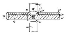
- FIG. 3is a cross-section of vehicle panel assembly 10 , and shows an exemplary weld joint 20 , weld openings 40 , 42 , as well as the welding equipment that is used to form the weld joint.
- the welding equipmentincludes first and second welding electrodes 44 , 46 that are used to form the weld joint 20 by resistance spot welding.
- Each exemplary electrode 44 , 46includes an outer dimension W′, which is the maximum width of the electrode at the working end that forms the weld joint.
- Welding electrodesare typically round in cross-section, making the outer dimension W′ simply equal to the diameter at or near the welding end, but other cross-sectional shapes are possible.
- weld joints 20are formed by resistance welding electrodes
- the dimensional ratiomay range from about 1.2 to about 5.0, inclusive, and preferably from about 1.5 to about 3.0.
- the corresponding weld openingcan range in width from about 12 mm to about 50 mm, inclusive.
- the precise dimensional ratiomay be influenced by factors such as the repeatability and accuracy of the welding equipment with respect to its location on the work pieces.
- weld opening 40 , 42has an inner dimension of about 25 mm in order to accommodate a welding electrode with an outer dimension of about 10 mm to 12 mm.
- the weld jointis surrounded by the weld opening in a way that ensures sufficient sound-damping performance, yet provides the welding electrode with enough clearance to account for manufacturing tolerances so that the welding electrodes do not contact the side walls of the opening during the welding process.
- Exemplary method 100generally includes the steps of providing a vehicle panel assembly, locating the panel assembly on the structural member, and welding the panel assembly to the structural member.
- Step 110includes providing a vehicle panel assembly having a main panel member, an adhesive layer and a sound-damping patch.
- At least one of the adhesive layer or the sound-damping patchincludes a weld opening such as one of those described above.
- more than one weld openingmay be included in the adhesive layer and/or the sound-damping patch, and the panel assembly can include more than one sound-damping patch and/or adhesive layer.
- Each of the sound-damping patch and the adhesive layermay be provided with or without weld openings.
- step 110provides a vehicle panel assembly 10 that includes a main panel member 22 , an adhesive layer 26 and a sound-damping patch 24 , where both the adhesive layer and the sound-damping patch have weld openings that are aligned with one another, as illustrated in FIG. 3 .
- Step 110may optionally include the exemplary sub-steps of providing a main blank and a sound-damping blank, applying the adhesive layer to attach the blanks together, and forming the blanks and the adhesive layer together into the vehicle panel assembly, as shown in FIG. 4 .
- sub-step 112includes providing the main blank and the sound-damping blank.
- the sound-damping blankmay be smaller than the main blank and, depending on the embodiment, may already include one or more weld openings.
- the sound-damping blank and the main blankwill ultimately become the sound-damping patch and the main panel member, respectively.
- Each blankmay be fabricated using conventional stamping or other techniques to provide blanks having the desired shapes and sizes and, in the case of the sound-damping blank, the desired shapes, sizes, locations, patterns and number of weld openings.
- Sub-step 114includes applying the adhesive layer to a rear surface of the sound-damping blank so that there is no adhesive in the area of the weld opening.
- the adhesive layermay then be used to attach the sound-damping blank to the main blank at a desired location—typically corresponding with an acoustically active region of the main panel member.
- the adhesive layercan be applied using a variety of techniques, including but not limited to spraying, coating, rolling, solvent casting, providing them in situ, or other adhesive application methods.
- the adhesive layerwhen the adhesive layer is applied to the rear surface of the sound-damping blank (e.g., by spraying or rolling), this automatically results in weld openings in both the sound-damping blank and the adhesive layer that are aligned with one another. It is also possible to apply adhesive layers to the main blank or to apply adhesive layers to both blanks. Once the adhesive layer has been applied, the sound-damping blank and the main blank are pressed together and the adhesive layer is cured; various known techniques may be used to accomplish this.
- Sub-step 116includes forming the main blank, the adhesive layer and the sound-damping blank together into the vehicle panel assembly.
- sub-step 116is completed after sub-step 114 so that the main blank is formed into the main panel member at the same time as the sound-damping blank is formed into the sound-damping patch.
- the formingmay be accomplished using conventional stamping, drawing, bending, or other metal forming techniques. It should be recognized that step 110 is only exemplary and may include more or less sub-steps than those shown in FIG. 4 . For example, one or more spot welds (such as spot welds 30 shown in FIG.
- Sub-steps 112 - 116may also be performed in a different order.
- the individual blanksmay be formed separately, as opposed to being integrally formed as one assembly, before adhering or attaching them to one another.
- Step 120includes locating the vehicle panel assembly on the structural member of the vehicle so that the weld opening is aligned with the structural member. Where more than one weld opening is provided, the plurality of weld openings may be aligned with the structural member. In one embodiment, all of the weld openings provided in the adhesive layer and/or sound-damping patch can be aligned with one or more structural members. This is illustrated in FIG. 1 , where vehicle panel assembly 10 is aligned with structural member 14 so that the pattern 60 of weld openings follows the shape of the structural member.
- Locating step 120may be accomplished by aligning other complimentary or mating features of the vehicle panel assembly and the structural member and/or may be assisted by automated assembly equipment known in the art that can be programmed to locate the panel assembly in a pre-determined location that aligns the weld opening with the structural member. Stated differently, the weld openings may actually be used as alignment features.
- the main panel memberis preferably in contact with or in close proximity to the structural member at the weld opening location or locations upon completion of step 120 to facilitate formation of the weld joints.
- Step 130includes welding the vehicle panel assembly to the structural member of the vehicle with at least one weld joint.
- the weld jointis located in the weld opening and is formed with material from the main panel member and the structural member.
- the adhesive layerincludes a weld opening but the sound-damping patch does not
- the weld jointincludes material from the sound-damping patch as well.
- both the sound-damping patch and the adhesive layerwill include one or more weld openings that line up with one another, as demonstrated in FIG. 3 . Any number and type of weld joints may be formed in each weld opening, many examples of which are described above.
- FIG. 4illustrates two non-limiting examples of welding step 130 , which include optional sub-steps 132 , 134 and 132 ′, 134 ′.
- One exampleincludes sub-steps 132 and 134 to form a resistance weld joint, while the other includes sub-steps 132 ′ and 134 ′ to form a laser weld joint.
- welding step 130includes aligning sub-step 132 , in which a welding electrode is aligned with the weld opening so that the welding electrode contacts the main panel member without contacting the sound-damping patch. An illustration of this is provided in FIG. 3 .
- the welding electrodemay be circular in cross-section and its center may be brought into general alignment with the center of the weld opening (where the weld opening is circular) or with the longitudinal center of the weld opening (where the weld opening is elongated or slot-shaped, for example). Alignment of the electrode in the weld opening typically occurs before the electrode comes into contact with the main panel member. The electrode may then be moved toward the main panel member so that they contact one another. A force may be applied to the main panel member using the electrode, thereby pressing the main panel member and the structural member together at the intended location of the weld joint.
- sub-step 134electric current is passed through the main panel member and the structural member but not through the sound-damping patch, and a resistance weld joint is formed.
- Skilled artisanswill appreciate that the amount of force and electrical current may vary with the individual application.
- FIG. 3shows a portion of the vehicle panel assembly after formation of the weld joint.
- welding electrode 44is aligned with weld openings 40 , 42 .
- Electrode 44is brought into contact with the main panel member 22
- electrode 46is brought into contact with structural member 14 from the opposite direction to pinch the structural and panel members 14 , 22 together.
- Electric currentis then passed between electrodes 44 , 46 and thus through each of the structural and main panel members 14 , 22 .
- Electric currentis not passed through the sound-damping patch 24 or the adhesive layer 26 , however.
- a resistance spot weld joint 20is thus formed in the weld openings 40 , 42 without burning, vaporizing, or causing out-gassing from adhesive layer 26 .
- Exemplary steps 132 and 134may also be used to describe other types of weld joints that use electric current to heat the materials to be welded together.
- a single welding electrodeis used in a drawn-arc technique to form the weld joint.
- a welding electrodeis brought into contact with the main panel member at the weld opening.
- the structural memberacts as electrical ground, and the welding electrode is electrically positive.
- electric currentis passed through the main panel member and the structural member as the positive welding electrode is pulled away from the main panel member to create an electrical arc, thereby localizing the current flow between positive and ground at the weld opening and forming the weld joint.
- resistance weld jointsapplies to resistance spot welds as well as some types of continuous or elongated weld joints.
- the welding electrode or electrodesmay be allowed to move along the surface of the main panel member within the weld opening while electric current is applied.
- a laser weld jointmay be formed using a method that includes sub-steps 132 ′ and 134 ′. These sub-steps may be used in addition to or in lieu of sub-steps 132 and 134 .
- welding step 130includes directing a laser beam at the weld opening in sub-step 132 ′. The laser beam impinges the main panel member without contacting the sound-damping patch or the adhesive layer. The laser beam may be a typical laser welding beam known in the art with sufficient power to melt the desired materials together.
- laser beamrefers to the portion of a column of laser light that is capable of melting the materials of the main panel member and the structural member when it is focused at the intended location of the weld joint. Skilled artisans will recognize that it may be possible to provide a column of laser light having variable power density across the width of the beam and that some low-power or unfocused laser light could contact the sound-damping patch and/or the adhesive layer without significantly melting either of those components. This type of extraneous laser light that is insufficient to perform a welding operation is not encompassed in the term “laser beam,” as used herein.
- the laser beamis directed at the weld opening from the side of the main panel member facing away from the structural member.
- the main panel memberis the first component the laser beam encounters or impinges along its path.
- the laser beammay be directed at the weld opening from the opposite direction so that the structural member is the first component the laser beam encounters along its path.
- laser beamsare directed at the weld opening from both sides.
- Exemplary sub-step 134 ′includes melting portions of the main panel and structural member together without melting the sound-damping patch so that a laser weld joint is formed. The melting of each member occurs when the laser beam is focused at the main panel member, the structural member, and/or at an interface between the members for a sufficient amount of time, given a particular laser beam power density.
- Exemplary steps 132 ′ and 134 ′ as described abovemay be used to describe various types of laser weld joints.
- the laser beammay be focused at the interface between the main panel member and remain in one location for weld joint formation, thus forming a laser spot weld.
- the laser beam and the main panel membermay move laterally in relation to each other during weld joint formation to form a continuous or elongated weld (such as weld 20 ′ shown in FIG. 2 ).
- the laser beammoves while the main panel member and structural stay in one place, but it is possible that the members are in motion while the laser beam is fixed in one place or that both the beam and the members are in motion.
- method 100may include various welding steps 130 including the formation of both resistance weld joints and laser weld joints.
- Skilled artisanswill also recognize that the same welding electrode or electrodes may be used multiple times sequentially at multiple weld openings to form resistance weld joints at each weld opening.
- a single pair of resistance spot welding electrodesmay be used to form weld joints at each weld opening included in weld opening pattern 60 shown in FIG. 1 by forming a weld joint at one weld opening, aligning with a different weld opening, forming one or more weld joints at the different weld opening, etc.
- a pair of opposing spot welding electrodesmay be attached to a robotic arm or other computer-controlled machine so that the electrodes can be programmed to form numerous weld joints at pre-determined locations, quickly moving from one pre-determined weld joint location to another.
- the accuracy of the location of such weld jointsdepends largely on the repeatability of the position of the components to be welded together.
- a robotic armthat is programmed to move to a particular location multiple times may do so with very high accuracy and repeatability.
- large componentssuch as automobile chassis include their own built-in tolerances so that not every chassis on the assembly line is in the exact same position as it reaches a robotic welding station.
- Providing vehicle panel assemblies that include weld openings formed in one or more layers of the assembliesmay assist with weld joint location repeatability by allowing welding equipment to use the weld openings as locator aids.
- automated welding equipmentmay use a feedback system with sensors (e.g., proximity sensors, vision systems, or other types of real-time feedback equipment) to fine-tune the weld joint location based on sensing an edge or other feature of a weld opening and positioning the welding electrodes or laser accordingly.
- sensorse.g., proximity sensors, vision systems, or other types of real-time feedback equipment
- Even a single weld opening in a vehicle panel assemblymay be used as a datum for locating the weld joint in a feedback system.
- the local thickness variation in some of the described vehicle panel assemblies that results from the inclusion of the weld openings in the sound damping patchmay be useful even where manual spot welding or other welding equipment is employed.
- spot welding electrode tipsmay be sized and configured to fit into the weld openings, providing positive mechanical positioning for the electrode tips and thus the corresponding weld joints.
- the terms “for example,” “e.g.,” “for instance,” “such as,” and “like,” and the verbs “comprising,” “having,” “including,” and their other verb forms, when used in conjunction with a listing of one or more components or other items,are each to be construed as open-ended, meaning that that the listing is not to be considered as excluding other, additional components or items.
- Other termsare to be construed using their broadest reasonable meaning unless they are used in a context that requires a different interpretation.
Landscapes
- Engineering & Computer Science (AREA)
- Chemical & Material Sciences (AREA)
- Combustion & Propulsion (AREA)
- Transportation (AREA)
- Mechanical Engineering (AREA)
- Manufacturing & Machinery (AREA)
- Body Structure For Vehicles (AREA)
- Vehicle Interior And Exterior Ornaments, Soundproofing, And Insulation (AREA)
Abstract
Description
Claims (22)
Priority Applications (5)
| Application Number | Priority Date | Filing Date | Title |
|---|---|---|---|
| US13/044,978US8403390B2 (en) | 2011-03-10 | 2011-03-10 | Vehicle panel assembly and method of attaching the same |
| DE102012203772ADE102012203772A1 (en) | 2011-03-10 | 2012-03-09 | VEHICLE PLATE ASSEMBLY AND METHOD FOR ATTACHING THE SAME |
| KR1020120024531AKR101664884B1 (en) | 2011-03-10 | 2012-03-09 | Vehicle panel assembly and method of attaching the same |
| JP2012052448AJP5997464B2 (en) | 2011-03-10 | 2012-03-09 | Vehicle panel assembly and method for connecting vehicle panel assemblies |
| CN201210063637.6ACN102673660B (en) | 2011-03-10 | 2012-03-12 | Automobile-used board component and the method being connected automobile-used board component |
Applications Claiming Priority (1)
| Application Number | Priority Date | Filing Date | Title |
|---|---|---|---|
| US13/044,978US8403390B2 (en) | 2011-03-10 | 2011-03-10 | Vehicle panel assembly and method of attaching the same |
Publications (2)
| Publication Number | Publication Date |
|---|---|
| US20120228899A1 US20120228899A1 (en) | 2012-09-13 |
| US8403390B2true US8403390B2 (en) | 2013-03-26 |
Family
ID=46705632
Family Applications (1)
| Application Number | Title | Priority Date | Filing Date |
|---|---|---|---|
| US13/044,978Active2031-04-01US8403390B2 (en) | 2011-03-10 | 2011-03-10 | Vehicle panel assembly and method of attaching the same |
Country Status (5)
| Country | Link |
|---|---|
| US (1) | US8403390B2 (en) |
| JP (1) | JP5997464B2 (en) |
| KR (1) | KR101664884B1 (en) |
| CN (1) | CN102673660B (en) |
| DE (1) | DE102012203772A1 (en) |
Cited By (8)
| Publication number | Priority date | Publication date | Assignee | Title |
|---|---|---|---|---|
| US20130049405A1 (en)* | 2011-08-31 | 2013-02-28 | Mazda Motor Corporation | Vehicle-body structure of vehicle and manufacturing method of the same |
| US20130049392A1 (en)* | 2011-08-31 | 2013-02-28 | Mazda Motor Corporation | Vehicle-body structure of vehicle and manufacturing method of the same |
| US20130049391A1 (en)* | 2011-08-31 | 2013-02-28 | Mazda Motor Corporation | Vehicle-body structure of vehicle and manufacturing method of the same |
| US20140182966A1 (en)* | 2011-03-22 | 2014-07-03 | Shiloh Industries, Inc. | Panel assembly having multi-layer patch for sound damping |
| US9080901B2 (en) | 2012-09-17 | 2015-07-14 | GM Global Technology Operations LLC | Screen unit, face plate unit, indicator instrument, indicator device, motor vehicle and method therefore |
| US20150314363A1 (en)* | 2014-04-30 | 2015-11-05 | GM Global Technology Operations LLC | Method of forming a vehicle body structure from a pre-welded blank assembly |
| US9434325B2 (en)* | 2014-04-23 | 2016-09-06 | Toyota Motor Engineering & Manufacturing North America, Inc. | Radiant barrier for automotive vehicle |
| US9908485B2 (en)* | 2014-11-06 | 2018-03-06 | Cadillac Products Automotive Company | Acoustic barrier assembly with acoustic seal |
Families Citing this family (7)
| Publication number | Priority date | Publication date | Assignee | Title |
|---|---|---|---|---|
| KR101985674B1 (en) | 2012-09-18 | 2019-06-04 | 삼성전자 주식회사 | Method of recognizing contactless user interface motion and System there-of |
| MX377708B (en)* | 2012-12-19 | 2025-03-11 | Henkel Ag & Co Kgaa | Method for the sound damping and/or sound insulation of components |
| US9524711B2 (en) | 2013-05-31 | 2016-12-20 | Shiloh Industries, Inc. | Panel assembly having structural adhesive joint |
| US9440682B2 (en) | 2013-06-28 | 2016-09-13 | GM Global Technology Operations LLC | Outward splayed mixed material longitudinal rail system |
| KR101543898B1 (en)* | 2013-12-24 | 2015-08-11 | 주식회사 포스코 | Steel having excellent impact toughness of welding zone and welding property |
| CN106573653B (en)* | 2014-08-29 | 2020-03-03 | 日本制铁株式会社 | Joint structure |
| CN107380091A (en)* | 2017-07-20 | 2017-11-24 | 苏州三基铸造装备股份有限公司 | Lightweight sound insulation board component |
Citations (113)
| Publication number | Priority date | Publication date | Assignee | Title |
|---|---|---|---|---|
| US2237623A (en) | 1935-01-31 | 1941-04-08 | Budd Edward G Mfg Co | Laminated sheet and stamped metal panel |
| US2815436A (en)* | 1955-06-21 | 1957-12-03 | Standard Oil Co | Welding aluminum clad steel |
| US2985747A (en)* | 1959-11-27 | 1961-05-23 | Titanium Metals Corp | Welding titanium |
| US3649430A (en) | 1965-10-21 | 1972-03-14 | American Cyanamid Co | Vibration damping laminates |
| US3800118A (en)* | 1966-09-21 | 1974-03-26 | O Becker | Resistance welding of sheet metal covered with non-metallic layers |
| JPS5262815A (en)* | 1975-11-17 | 1977-05-24 | Mitsubishi Motors Corp | Method of manufacturing sound insulation double wall |
| US4223073A (en) | 1978-10-30 | 1980-09-16 | Minnesota Mining And Manufacturing Company | High-temperature damping composite |
| JPS57142780A (en)* | 1981-02-26 | 1982-09-03 | Hashimoto Forming Co Ltd | Welding method for plate material having insulation material on one side |
| JPS57187187A (en)* | 1981-05-15 | 1982-11-17 | Matsushita Electric Works Ltd | Welding method for resin coated member |
| US4655496A (en) | 1984-11-07 | 1987-04-07 | Dr. Alois Stankiewica GmbH | Motor vehicle noise insulation |
| US4705139A (en) | 1985-09-06 | 1987-11-10 | Dr. Alois Stankiewicz Gmbh | Sound insulation part for surfaces |
| US4791765A (en)* | 1981-12-28 | 1988-12-20 | Ford Motor Company | Synthetic material structural body panel |
| US4851271A (en) | 1987-10-01 | 1989-07-25 | Soundwich Incorporated | Sound dampened automotive enclosure such as an oil pan |
| JPH01209200A (en)* | 1988-02-17 | 1989-08-22 | Kimoto & Co Ltd | Decoration of japanned material with photographic image |
| US5143755A (en) | 1987-10-01 | 1992-09-01 | Soundwich, Inc. | Method of using a sound damping composition |
| US5180189A (en)* | 1991-09-03 | 1993-01-19 | General Motors Corporation | Vehicle steering column installation |
| US5195795A (en) | 1992-04-01 | 1993-03-23 | Cannera Raymond C | Automotive vehicle seat assembly fully retractable below the vehicle's floor |
| JPH05185956A (en)* | 1992-01-09 | 1993-07-27 | Nissan Motor Co Ltd | Car body structure |
| US5233832A (en) | 1992-05-14 | 1993-08-10 | Soundwich, Inc. | Damped heat shield |
| US5271142A (en) | 1991-05-09 | 1993-12-21 | Soundwich, Inc. | Method for producing a sound-dampened automotive enclosure |
| US5282917A (en)* | 1989-06-14 | 1994-02-01 | Ivy Hill Corporation | Method of making a product having a concealed message |
| US5407034A (en) | 1994-01-31 | 1995-04-18 | Pre Finish Metals Incorporated | Noise damped brake pad assembly |
| US5416962A (en) | 1993-12-08 | 1995-05-23 | Eagle-Picher Industries, Inc. | Method of manufacture of vibration damper |
| US5418073A (en) | 1993-10-25 | 1995-05-23 | Pre Finish Metals Incorporated | Method of forming noise-damping composite with externally galvanized surfaces and composite formed thereby |
| US5557078A (en) | 1994-09-14 | 1996-09-17 | Cascade Engineering, Inc. | Acoustical barrier |
| US5580122A (en)* | 1994-03-17 | 1996-12-03 | Mercedes-Benz Ag | Passenger vehicle scuttle and cockpit region construction |
| US5590524A (en) | 1992-05-14 | 1997-01-07 | Soundwich, Inc. | Damped heat shield |
| US5631451A (en) | 1991-02-04 | 1997-05-20 | Hino Jidosha Kogyo Kabushiki Kaisha | Device for reducing noise produced by automotive vehicle components |
| US5796055A (en) | 1997-01-13 | 1998-08-18 | Ppg Industries, Inc. | Sound absorbing article and method of making same |
| US5842686A (en) | 1995-11-01 | 1998-12-01 | Pre Finish Metals Incorporated | Patterned noise damping composite |
| US5851342A (en) | 1996-11-14 | 1998-12-22 | Material Sciences Corporation | Method and apparatus for forming a laminate |
| US5975609A (en) | 1996-07-26 | 1999-11-02 | Cascade Engineering, Inc. | Sound insulating layer with integral boot |
| US5979964A (en) | 1997-10-15 | 1999-11-09 | Lear Corporation | Double pivoting stowable seat |
| US6024190A (en) | 1997-01-07 | 2000-02-15 | Cascade Engineering, Inc. | Acoustical barrier with ribbed decoupler |
| US6036797A (en)* | 1992-08-28 | 2000-03-14 | Citizen Watch Co., Ltd. | Process of producing IC cards |
| US6089349A (en) | 1998-02-11 | 2000-07-18 | Cascade Engineering, Inc. | Sound absorber mat with integrally molded retainer |
| US6092854A (en) | 1997-01-08 | 2000-07-25 | Cascade Engineering, Inc. | Mat with integral wire harness fastener and channel |
| US6103152A (en) | 1998-07-31 | 2000-08-15 | 3M Innovative Properties Co. | Articles that include a polymer foam and method for preparing same |
| US6109481A (en) | 1996-07-10 | 2000-08-29 | Material Sciences Corporation | Powder atomizer |
| US6179372B1 (en)* | 1998-09-16 | 2001-01-30 | Toyota Jidosha Kabushiki Kaisha | Front portion structure of an automobile vehicle body |
| US6202462B1 (en) | 1998-05-26 | 2001-03-20 | Material Sciences Corporation | Method of forming noise-damping material with ultra-thin viscoelastic layer |
| US6283541B1 (en)* | 1999-12-21 | 2001-09-04 | Hyundai Motor Company | Rear roof rail reinforcement structure for automobile |
| US6302466B1 (en) | 1998-03-12 | 2001-10-16 | Rieter Automotive (International) Ag | Vibration-damping, noise-reducing, heat-shielding vehicle trim |
| US6368438B1 (en) | 1998-11-05 | 2002-04-09 | Sika Corporation | Sound deadening and structural reinforcement compositions and methods of using the same |
| US6375255B1 (en) | 1999-08-10 | 2002-04-23 | Toyota Jidosha Kabushiki Kaisha | Rear passenger seat in vehicle compartment |
| US6435590B2 (en) | 1998-03-03 | 2002-08-20 | Mazda Motor Corporation | Seat device of a vehicle |
| US6455146B1 (en) | 2000-10-31 | 2002-09-24 | Sika Corporation | Expansible synthetic resin baffle with magnetic attachment |
| US6465110B1 (en) | 2000-10-10 | 2002-10-15 | Material Sciences Corporation | Metal felt laminate structures |
| US6481545B1 (en) | 2001-03-30 | 2002-11-19 | Nichias Corporation | Vibration damping shim structure |
| US6585068B2 (en)* | 2000-09-25 | 2003-07-01 | Suzuki Motor Corporation | Front vehicle body construction |
| US6589607B1 (en) | 2000-06-29 | 2003-07-08 | Material Sciences Corporation | Method of coating a continuously moving substrate with thermoset material and corresponding apparatus |
| US6592968B1 (en) | 1999-10-26 | 2003-07-15 | Usinor | Composite sheet intended for drawing, comprising a main sheet and at least one adhesively bonded patching sheet blank as a patch |
| US6601909B2 (en)* | 2000-03-13 | 2003-08-05 | Kikuchi Co., Ltd. | Tailored blank article and manufacturing method of the same |
| US6621658B1 (en) | 1999-07-14 | 2003-09-16 | Material Sciences Corporation | Vibration damping laminate with vibration isolating cut therein |
| US20040007891A1 (en)* | 1996-03-19 | 2004-01-15 | Kinya Aota | Manufacturing method of structure body and structure body formed |
| US20040018353A1 (en) | 2002-07-25 | 2004-01-29 | L&L Products, Inc. | Composite metal foam damping/reinforcement structure |
| US20040058181A1 (en) | 2000-12-13 | 2004-03-25 | Anne-Marie Garnault | Multi-layer metal sandwich materials comprising epoxy-based adhesive systems |
| US6722720B2 (en) | 2002-02-04 | 2004-04-20 | Ford Global Technologies, Llc | Engine compartment sound baffle |
| US20040076841A1 (en) | 2000-12-16 | 2004-04-22 | Rauf Sauer | Multi-layered composite material with organic sandwich layers based on rubber |
| US20040110905A1 (en) | 2001-03-06 | 2004-06-10 | Isao Kubota | Acrylic rubber composition and vulcanizate |
| US20040129493A1 (en) | 2003-01-07 | 2004-07-08 | Cascade Engineering, Inc. | Molded lightweight foam acoustical barrier and method of attenuating noise |
| US20040138321A1 (en) | 2002-10-23 | 2004-07-15 | Nichias Corporation | Thermally expandable material, method for producing the same and soundproof sheet for automobile |
| US20040157079A1 (en) | 2001-08-09 | 2004-08-12 | Paolo Cittadini | Method for forming a vibration-damping sheet or panel, and articles obtained therewith |
| US6805219B2 (en) | 2001-07-27 | 2004-10-19 | Toyoda Gosei Co., Ltd. | Engine cover |
| US20040214008A1 (en) | 2003-04-25 | 2004-10-28 | Dobrusky Scott R. | Flexible magnetic damping laminate with thermosetting adhesive layer |
| US6827394B2 (en) | 2001-10-16 | 2004-12-07 | Honda Giken Kogyo Kabushiki Kaisha | Vehicle seat system |
| US20050019590A1 (en) | 2001-09-10 | 2005-01-27 | Percy Josefsson | Vibration damping material and vibration damper |
| US6869138B2 (en) | 2002-08-23 | 2005-03-22 | Daimlerchrysler Corporation | Underfloor stowage of a folding seat in a vehicle |
| US7040691B1 (en) | 2004-12-06 | 2006-05-09 | Material Sciences Corporation | Vehicle floor tub having a laminated structure |
| US7048330B2 (en) | 2002-09-27 | 2006-05-23 | Faurecia Automotive Seating Canada Limited | Vehicle seat assembly for storage in a vehicle floor tub |
| US20060134449A1 (en) | 2004-12-20 | 2006-06-22 | Sigler David R | Weldable metal composites and methods |
| US20060137944A1 (en) | 2004-12-23 | 2006-06-29 | Material Sciences Corporation | Drum brake shoe and backplate made from constrained layer viscoelastic laminates |
| US7070848B2 (en) | 2002-10-21 | 2006-07-04 | Cascade Engineering, Inc. | Vehicle acoustic barrier |
| US20060169557A1 (en) | 2005-02-01 | 2006-08-03 | Material Sciences Corporation | Constrained layer viscoelastic laminate tuned mass damper and method of use |
| US20060169341A1 (en) | 2005-02-01 | 2006-08-03 | Material Sciences Corporation | Internally damped laminated tube |
| US7094478B1 (en) | 2002-09-13 | 2006-08-22 | Material Sciences Corporation, Engineered Materials And Solutions Group, Inc. | Magnetic damping |
| US7121609B2 (en) | 2002-09-20 | 2006-10-17 | Intier Automotive Inc. | Stow in floor seat assembly with main lateral displacement |
| US7125613B1 (en) | 2005-03-07 | 2006-10-24 | Material Sciences Corporation, Engineered Materials And Solutions Group, Inc. | Coated metal article and method of making same |
| US20060266385A1 (en) | 2005-05-26 | 2006-11-30 | Material Sciences Corporation | Home appliance structure with integral noise attenuation |
| US7172800B2 (en) | 2003-11-03 | 2007-02-06 | Material Sciences Corporation | Sheet molding compound damper component, and methods for making and using the same |
| US7186442B2 (en) | 2003-06-11 | 2007-03-06 | Sika Technology Ag | Constrained layer damper |
| US7218189B2 (en) | 2003-11-04 | 2007-05-15 | Epcos Ag | SAW component with adhesive location and use thereof |
| US7219946B2 (en) | 2002-09-20 | 2007-05-22 | Intier Automotive Inc. | Stow in floor seat assembly with automatic lateral displacement |
| US20070186614A1 (en) | 2004-02-19 | 2007-08-16 | Fabrice Pinard | Method for producing a composite part |
| US20070197713A1 (en) | 2005-08-22 | 2007-08-23 | Nippon Shokubai Co., Ltd. | Emulsion for vibration damping materials |
| US7288290B2 (en) | 2004-05-26 | 2007-10-30 | Ppg Industries Ohio, Inc. | Process for applying multi-component composite coatings to substrates to provide sound damping and print-through resistance |
| US7291241B2 (en) | 2001-02-23 | 2007-11-06 | The Gates Corporation | Bonded part and method for producing same |
| US7325865B2 (en)* | 2004-12-06 | 2008-02-05 | Nissan Motor Co., Ltd. | Vehicle rear body structure |
| US7360520B2 (en) | 2006-03-27 | 2008-04-22 | Material Sciences Corporation | Damped windage tray and method of making same |
| US7364221B2 (en) | 2005-10-06 | 2008-04-29 | Henkel Kommanditgesellschaft Auf Aktien | Reduction of vibration transfer |
| US7429713B2 (en)* | 2006-01-27 | 2008-09-30 | Gm Global Technology Operations, Inc. | Method for improving single sided resistance spot welds |
| US20080236739A1 (en) | 2006-12-05 | 2008-10-02 | Rolls-Royce Plc | Method of applying a constrained layer damping material |
| US20080248274A1 (en) | 2007-04-06 | 2008-10-09 | Material Sciences Corporation | High Damping, High Stiffness Multilayer Metal Polymer Sandwich Structure and Method |
| US20080246312A1 (en)* | 2007-04-06 | 2008-10-09 | Hino Motors, Ltd. | Rear section structure of vehicle |
| US20080245126A1 (en) | 2007-04-05 | 2008-10-09 | Material Sciences Corporation | Method of Stamping Multilayer Sheets |
| US7444874B2 (en) | 2006-07-03 | 2008-11-04 | Material Sciences Corporation | Method of determining damping of an article of manufacture and system for determining damping performance |
| US7484785B2 (en) | 2003-06-05 | 2009-02-03 | Intier Automotive Inc. | Automatic tumble and slide vehicle seat assembly |
| US20090127026A1 (en) | 2005-02-10 | 2009-05-21 | Rogier Theodorus Siardus Maria Mandos | Covering Element Comprising a Sound Absorbing Element |
| US20090142538A1 (en) | 2007-06-08 | 2009-06-04 | Gm Global Technology Operations, Inc. | Corrosion resistant precoated laminated steel |
| US20090183821A1 (en) | 2008-01-23 | 2009-07-23 | Intellectual Property Holdings, Llc | Constrained layer damping system and method of making the same |
| US7585559B2 (en) | 2003-06-03 | 2009-09-08 | Intellectual Property Holdings, Llc | Foam barrier heat shield |
| US20090252989A1 (en) | 2008-04-08 | 2009-10-08 | Material Sciences Corporation | Laminated Viscoelastic Damping Structure And Method Of Making The Same |
| US20090249627A1 (en) | 2008-04-03 | 2009-10-08 | Material Sciences Corporation | Method of manufacturing laminated damping structure with vulcanized rubber as viscoelastic core |
| US20090269562A1 (en) | 2008-04-25 | 2009-10-29 | Material Sciences Corporation | Bimetal Laminate Structure And Method Of Making The Same |
| US20100013255A1 (en) | 2007-02-12 | 2010-01-21 | Rieter Technologies Ag | Constrained Layer Damping for Vehicle |
| US20100132110A1 (en) | 2008-12-01 | 2010-06-03 | Material Sciences Corporation | Bimetal laminate structure and method of making the same |
| US7748184B1 (en) | 2005-02-09 | 2010-07-06 | Intellectual Property Holdings, Llc | Body panel having improved stiffness and method of making |
| US7784165B2 (en) | 2006-04-19 | 2010-08-31 | Material Science Corporation | Method of forming a panel constrained layer damper treatment |
| US7819452B2 (en)* | 2008-05-12 | 2010-10-26 | United States Council For Automotive Research | Automotive structural joint and method of making same |
| US7828357B2 (en)* | 2007-01-30 | 2010-11-09 | Honda Motor Co., Ltd. | Welding arrangement for vehicle body panels |
| US7834292B2 (en)* | 2006-10-11 | 2010-11-16 | Gm Global Technology Operations, Inc. | Method for single side welding of laminate steel |
| US7919174B2 (en) | 2007-07-20 | 2011-04-05 | GM Global Technology Operations LLC | Tailored core laminated sheet metal |
| US7985317B2 (en)* | 2007-06-20 | 2011-07-26 | Mazda Motor Corporation | Joining structure of metal works |
Family Cites Families (10)
| Publication number | Priority date | Publication date | Assignee | Title |
|---|---|---|---|---|
| JPS6136478U (en)* | 1984-08-09 | 1986-03-06 | トヨタ自動車株式会社 | Vibration damping structure for vehicle darts section |
| JPS6230958U (en)* | 1985-08-10 | 1987-02-24 | ||
| JPH0694199B2 (en)* | 1990-07-12 | 1994-11-24 | 日本セキソー工業株式会社 | Steel plate restraint type damping material for automobiles |
| JPH0715450U (en)* | 1993-08-27 | 1995-03-14 | ダイハツ工業株式会社 | Soundproof bulkhead structure for vehicle body |
| JP3127694B2 (en)* | 1993-11-25 | 2001-01-29 | トヨタ自動車株式会社 | Front side member reinforcement structure |
| JPH09206953A (en)* | 1996-02-06 | 1997-08-12 | Nissan Motor Co Ltd | Spot welding equipment |
| US6520849B1 (en)* | 2000-03-31 | 2003-02-18 | Delphi Technologies, Inc. | Integrated structural HVAC system |
| DE102004016533A1 (en)* | 2003-12-18 | 2005-10-27 | Intier Automotive Interiors Gmbh | crossbeam |
| EP1717130A1 (en)* | 2005-04-25 | 2006-11-02 | Alcan Technology & Management Ltd. | Instrument panel carrier structure |
| CN201272334Y (en)* | 2008-08-13 | 2009-07-15 | 瑞阳汽车零部件(仙桃)有限公司 | Composite shock-absorbing silencing sheet |
- 2011
- 2011-03-10USUS13/044,978patent/US8403390B2/enactiveActive
- 2012
- 2012-03-09KRKR1020120024531Apatent/KR101664884B1/ennot_activeExpired - Fee Related
- 2012-03-09DEDE102012203772Apatent/DE102012203772A1/enactivePending
- 2012-03-09JPJP2012052448Apatent/JP5997464B2/ennot_activeExpired - Fee Related
- 2012-03-12CNCN201210063637.6Apatent/CN102673660B/enactiveActive
Patent Citations (115)
| Publication number | Priority date | Publication date | Assignee | Title |
|---|---|---|---|---|
| US2237623A (en) | 1935-01-31 | 1941-04-08 | Budd Edward G Mfg Co | Laminated sheet and stamped metal panel |
| US2815436A (en)* | 1955-06-21 | 1957-12-03 | Standard Oil Co | Welding aluminum clad steel |
| US2985747A (en)* | 1959-11-27 | 1961-05-23 | Titanium Metals Corp | Welding titanium |
| US3649430A (en) | 1965-10-21 | 1972-03-14 | American Cyanamid Co | Vibration damping laminates |
| US3800118A (en)* | 1966-09-21 | 1974-03-26 | O Becker | Resistance welding of sheet metal covered with non-metallic layers |
| JPS5262815A (en)* | 1975-11-17 | 1977-05-24 | Mitsubishi Motors Corp | Method of manufacturing sound insulation double wall |
| US4223073A (en) | 1978-10-30 | 1980-09-16 | Minnesota Mining And Manufacturing Company | High-temperature damping composite |
| JPS57142780A (en)* | 1981-02-26 | 1982-09-03 | Hashimoto Forming Co Ltd | Welding method for plate material having insulation material on one side |
| JPS57187187A (en)* | 1981-05-15 | 1982-11-17 | Matsushita Electric Works Ltd | Welding method for resin coated member |
| US4791765A (en)* | 1981-12-28 | 1988-12-20 | Ford Motor Company | Synthetic material structural body panel |
| US4655496A (en) | 1984-11-07 | 1987-04-07 | Dr. Alois Stankiewica GmbH | Motor vehicle noise insulation |
| US4705139A (en) | 1985-09-06 | 1987-11-10 | Dr. Alois Stankiewicz Gmbh | Sound insulation part for surfaces |
| US5143755A (en) | 1987-10-01 | 1992-09-01 | Soundwich, Inc. | Method of using a sound damping composition |
| US4851271A (en) | 1987-10-01 | 1989-07-25 | Soundwich Incorporated | Sound dampened automotive enclosure such as an oil pan |
| JPH01209200A (en)* | 1988-02-17 | 1989-08-22 | Kimoto & Co Ltd | Decoration of japanned material with photographic image |
| US5282917A (en)* | 1989-06-14 | 1994-02-01 | Ivy Hill Corporation | Method of making a product having a concealed message |
| US5631451A (en) | 1991-02-04 | 1997-05-20 | Hino Jidosha Kogyo Kabushiki Kaisha | Device for reducing noise produced by automotive vehicle components |
| US5271142A (en) | 1991-05-09 | 1993-12-21 | Soundwich, Inc. | Method for producing a sound-dampened automotive enclosure |
| US5180189A (en)* | 1991-09-03 | 1993-01-19 | General Motors Corporation | Vehicle steering column installation |
| JPH05185956A (en)* | 1992-01-09 | 1993-07-27 | Nissan Motor Co Ltd | Car body structure |
| US5195795A (en) | 1992-04-01 | 1993-03-23 | Cannera Raymond C | Automotive vehicle seat assembly fully retractable below the vehicle's floor |
| US5347810A (en) | 1992-05-14 | 1994-09-20 | Soundwich, Inc. | Damped heat shield |
| US5233832A (en) | 1992-05-14 | 1993-08-10 | Soundwich, Inc. | Damped heat shield |
| US5590524A (en) | 1992-05-14 | 1997-01-07 | Soundwich, Inc. | Damped heat shield |
| US6036797A (en)* | 1992-08-28 | 2000-03-14 | Citizen Watch Co., Ltd. | Process of producing IC cards |
| US5418073A (en) | 1993-10-25 | 1995-05-23 | Pre Finish Metals Incorporated | Method of forming noise-damping composite with externally galvanized surfaces and composite formed thereby |
| US5416962A (en) | 1993-12-08 | 1995-05-23 | Eagle-Picher Industries, Inc. | Method of manufacture of vibration damper |
| US5407034A (en) | 1994-01-31 | 1995-04-18 | Pre Finish Metals Incorporated | Noise damped brake pad assembly |
| US5580122A (en)* | 1994-03-17 | 1996-12-03 | Mercedes-Benz Ag | Passenger vehicle scuttle and cockpit region construction |
| US5557078A (en) | 1994-09-14 | 1996-09-17 | Cascade Engineering, Inc. | Acoustical barrier |
| US5842686A (en) | 1995-11-01 | 1998-12-01 | Pre Finish Metals Incorporated | Patterned noise damping composite |
| US20040007891A1 (en)* | 1996-03-19 | 2004-01-15 | Kinya Aota | Manufacturing method of structure body and structure body formed |
| US6109481A (en) | 1996-07-10 | 2000-08-29 | Material Sciences Corporation | Powder atomizer |
| US5975609A (en) | 1996-07-26 | 1999-11-02 | Cascade Engineering, Inc. | Sound insulating layer with integral boot |
| US5851342A (en) | 1996-11-14 | 1998-12-22 | Material Sciences Corporation | Method and apparatus for forming a laminate |
| US6024190A (en) | 1997-01-07 | 2000-02-15 | Cascade Engineering, Inc. | Acoustical barrier with ribbed decoupler |
| US6092854A (en) | 1997-01-08 | 2000-07-25 | Cascade Engineering, Inc. | Mat with integral wire harness fastener and channel |
| US5796055A (en) | 1997-01-13 | 1998-08-18 | Ppg Industries, Inc. | Sound absorbing article and method of making same |
| US5979964A (en) | 1997-10-15 | 1999-11-09 | Lear Corporation | Double pivoting stowable seat |
| US6089349A (en) | 1998-02-11 | 2000-07-18 | Cascade Engineering, Inc. | Sound absorber mat with integrally molded retainer |
| US6435590B2 (en) | 1998-03-03 | 2002-08-20 | Mazda Motor Corporation | Seat device of a vehicle |
| US6302466B1 (en) | 1998-03-12 | 2001-10-16 | Rieter Automotive (International) Ag | Vibration-damping, noise-reducing, heat-shielding vehicle trim |
| US6202462B1 (en) | 1998-05-26 | 2001-03-20 | Material Sciences Corporation | Method of forming noise-damping material with ultra-thin viscoelastic layer |
| US6103152A (en) | 1998-07-31 | 2000-08-15 | 3M Innovative Properties Co. | Articles that include a polymer foam and method for preparing same |
| US6179372B1 (en)* | 1998-09-16 | 2001-01-30 | Toyota Jidosha Kabushiki Kaisha | Front portion structure of an automobile vehicle body |
| US6368438B1 (en) | 1998-11-05 | 2002-04-09 | Sika Corporation | Sound deadening and structural reinforcement compositions and methods of using the same |
| US6621658B1 (en) | 1999-07-14 | 2003-09-16 | Material Sciences Corporation | Vibration damping laminate with vibration isolating cut therein |
| US6375255B1 (en) | 1999-08-10 | 2002-04-23 | Toyota Jidosha Kabushiki Kaisha | Rear passenger seat in vehicle compartment |
| US6592968B1 (en) | 1999-10-26 | 2003-07-15 | Usinor | Composite sheet intended for drawing, comprising a main sheet and at least one adhesively bonded patching sheet blank as a patch |
| US6283541B1 (en)* | 1999-12-21 | 2001-09-04 | Hyundai Motor Company | Rear roof rail reinforcement structure for automobile |
| US6601909B2 (en)* | 2000-03-13 | 2003-08-05 | Kikuchi Co., Ltd. | Tailored blank article and manufacturing method of the same |
| US6589607B1 (en) | 2000-06-29 | 2003-07-08 | Material Sciences Corporation | Method of coating a continuously moving substrate with thermoset material and corresponding apparatus |
| US6585068B2 (en)* | 2000-09-25 | 2003-07-01 | Suzuki Motor Corporation | Front vehicle body construction |
| US6465110B1 (en) | 2000-10-10 | 2002-10-15 | Material Sciences Corporation | Metal felt laminate structures |
| US6455146B1 (en) | 2000-10-31 | 2002-09-24 | Sika Corporation | Expansible synthetic resin baffle with magnetic attachment |
| US20040058181A1 (en) | 2000-12-13 | 2004-03-25 | Anne-Marie Garnault | Multi-layer metal sandwich materials comprising epoxy-based adhesive systems |
| US20040076841A1 (en) | 2000-12-16 | 2004-04-22 | Rauf Sauer | Multi-layered composite material with organic sandwich layers based on rubber |
| US7291241B2 (en) | 2001-02-23 | 2007-11-06 | The Gates Corporation | Bonded part and method for producing same |
| US20040110905A1 (en) | 2001-03-06 | 2004-06-10 | Isao Kubota | Acrylic rubber composition and vulcanizate |
| US6481545B1 (en) | 2001-03-30 | 2002-11-19 | Nichias Corporation | Vibration damping shim structure |
| US6805219B2 (en) | 2001-07-27 | 2004-10-19 | Toyoda Gosei Co., Ltd. | Engine cover |
| US20040157079A1 (en) | 2001-08-09 | 2004-08-12 | Paolo Cittadini | Method for forming a vibration-damping sheet or panel, and articles obtained therewith |
| US20050019590A1 (en) | 2001-09-10 | 2005-01-27 | Percy Josefsson | Vibration damping material and vibration damper |
| US6827394B2 (en) | 2001-10-16 | 2004-12-07 | Honda Giken Kogyo Kabushiki Kaisha | Vehicle seat system |
| US6722720B2 (en) | 2002-02-04 | 2004-04-20 | Ford Global Technologies, Llc | Engine compartment sound baffle |
| US20040018353A1 (en) | 2002-07-25 | 2004-01-29 | L&L Products, Inc. | Composite metal foam damping/reinforcement structure |
| US6869138B2 (en) | 2002-08-23 | 2005-03-22 | Daimlerchrysler Corporation | Underfloor stowage of a folding seat in a vehicle |
| US7094478B1 (en) | 2002-09-13 | 2006-08-22 | Material Sciences Corporation, Engineered Materials And Solutions Group, Inc. | Magnetic damping |
| US7121609B2 (en) | 2002-09-20 | 2006-10-17 | Intier Automotive Inc. | Stow in floor seat assembly with main lateral displacement |
| US7219946B2 (en) | 2002-09-20 | 2007-05-22 | Intier Automotive Inc. | Stow in floor seat assembly with automatic lateral displacement |
| US7048330B2 (en) | 2002-09-27 | 2006-05-23 | Faurecia Automotive Seating Canada Limited | Vehicle seat assembly for storage in a vehicle floor tub |
| US7070848B2 (en) | 2002-10-21 | 2006-07-04 | Cascade Engineering, Inc. | Vehicle acoustic barrier |
| US20040138321A1 (en) | 2002-10-23 | 2004-07-15 | Nichias Corporation | Thermally expandable material, method for producing the same and soundproof sheet for automobile |
| US20040129493A1 (en) | 2003-01-07 | 2004-07-08 | Cascade Engineering, Inc. | Molded lightweight foam acoustical barrier and method of attenuating noise |
| US20040214008A1 (en) | 2003-04-25 | 2004-10-28 | Dobrusky Scott R. | Flexible magnetic damping laminate with thermosetting adhesive layer |
| US7585559B2 (en) | 2003-06-03 | 2009-09-08 | Intellectual Property Holdings, Llc | Foam barrier heat shield |
| US7484785B2 (en) | 2003-06-05 | 2009-02-03 | Intier Automotive Inc. | Automatic tumble and slide vehicle seat assembly |
| US7186442B2 (en) | 2003-06-11 | 2007-03-06 | Sika Technology Ag | Constrained layer damper |
| US7393575B2 (en) | 2003-11-03 | 2008-07-01 | Material Sciences Corporation | Sheet molding compound damper component, and methods for making and using the same |
| US7172800B2 (en) | 2003-11-03 | 2007-02-06 | Material Sciences Corporation | Sheet molding compound damper component, and methods for making and using the same |
| US7218189B2 (en) | 2003-11-04 | 2007-05-15 | Epcos Ag | SAW component with adhesive location and use thereof |
| US20070186614A1 (en) | 2004-02-19 | 2007-08-16 | Fabrice Pinard | Method for producing a composite part |
| US7288290B2 (en) | 2004-05-26 | 2007-10-30 | Ppg Industries Ohio, Inc. | Process for applying multi-component composite coatings to substrates to provide sound damping and print-through resistance |
| US7040691B1 (en) | 2004-12-06 | 2006-05-09 | Material Sciences Corporation | Vehicle floor tub having a laminated structure |
| US7325865B2 (en)* | 2004-12-06 | 2008-02-05 | Nissan Motor Co., Ltd. | Vehicle rear body structure |
| US20060134449A1 (en) | 2004-12-20 | 2006-06-22 | Sigler David R | Weldable metal composites and methods |
| US20060137944A1 (en) | 2004-12-23 | 2006-06-29 | Material Sciences Corporation | Drum brake shoe and backplate made from constrained layer viscoelastic laminates |
| US20060169557A1 (en) | 2005-02-01 | 2006-08-03 | Material Sciences Corporation | Constrained layer viscoelastic laminate tuned mass damper and method of use |
| US20060169341A1 (en) | 2005-02-01 | 2006-08-03 | Material Sciences Corporation | Internally damped laminated tube |
| US7748184B1 (en) | 2005-02-09 | 2010-07-06 | Intellectual Property Holdings, Llc | Body panel having improved stiffness and method of making |
| US20090127026A1 (en) | 2005-02-10 | 2009-05-21 | Rogier Theodorus Siardus Maria Mandos | Covering Element Comprising a Sound Absorbing Element |
| US7125613B1 (en) | 2005-03-07 | 2006-10-24 | Material Sciences Corporation, Engineered Materials And Solutions Group, Inc. | Coated metal article and method of making same |
| US20060266385A1 (en) | 2005-05-26 | 2006-11-30 | Material Sciences Corporation | Home appliance structure with integral noise attenuation |
| US20070197713A1 (en) | 2005-08-22 | 2007-08-23 | Nippon Shokubai Co., Ltd. | Emulsion for vibration damping materials |
| US7364221B2 (en) | 2005-10-06 | 2008-04-29 | Henkel Kommanditgesellschaft Auf Aktien | Reduction of vibration transfer |
| US7429713B2 (en)* | 2006-01-27 | 2008-09-30 | Gm Global Technology Operations, Inc. | Method for improving single sided resistance spot welds |
| US7360520B2 (en) | 2006-03-27 | 2008-04-22 | Material Sciences Corporation | Damped windage tray and method of making same |
| US7784165B2 (en) | 2006-04-19 | 2010-08-31 | Material Science Corporation | Method of forming a panel constrained layer damper treatment |
| US7444874B2 (en) | 2006-07-03 | 2008-11-04 | Material Sciences Corporation | Method of determining damping of an article of manufacture and system for determining damping performance |
| US7834292B2 (en)* | 2006-10-11 | 2010-11-16 | Gm Global Technology Operations, Inc. | Method for single side welding of laminate steel |
| US20080236739A1 (en) | 2006-12-05 | 2008-10-02 | Rolls-Royce Plc | Method of applying a constrained layer damping material |
| US7828357B2 (en)* | 2007-01-30 | 2010-11-09 | Honda Motor Co., Ltd. | Welding arrangement for vehicle body panels |
| US20100013255A1 (en) | 2007-02-12 | 2010-01-21 | Rieter Technologies Ag | Constrained Layer Damping for Vehicle |
| US20080245126A1 (en) | 2007-04-05 | 2008-10-09 | Material Sciences Corporation | Method of Stamping Multilayer Sheets |
| US20080248274A1 (en) | 2007-04-06 | 2008-10-09 | Material Sciences Corporation | High Damping, High Stiffness Multilayer Metal Polymer Sandwich Structure and Method |
| US20080246312A1 (en)* | 2007-04-06 | 2008-10-09 | Hino Motors, Ltd. | Rear section structure of vehicle |
| US20090142538A1 (en) | 2007-06-08 | 2009-06-04 | Gm Global Technology Operations, Inc. | Corrosion resistant precoated laminated steel |
| US7985317B2 (en)* | 2007-06-20 | 2011-07-26 | Mazda Motor Corporation | Joining structure of metal works |
| US7919174B2 (en) | 2007-07-20 | 2011-04-05 | GM Global Technology Operations LLC | Tailored core laminated sheet metal |
| US20090183821A1 (en) | 2008-01-23 | 2009-07-23 | Intellectual Property Holdings, Llc | Constrained layer damping system and method of making the same |
| US20090249627A1 (en) | 2008-04-03 | 2009-10-08 | Material Sciences Corporation | Method of manufacturing laminated damping structure with vulcanized rubber as viscoelastic core |
| US20090252989A1 (en) | 2008-04-08 | 2009-10-08 | Material Sciences Corporation | Laminated Viscoelastic Damping Structure And Method Of Making The Same |
| US20090269562A1 (en) | 2008-04-25 | 2009-10-29 | Material Sciences Corporation | Bimetal Laminate Structure And Method Of Making The Same |
| US7819452B2 (en)* | 2008-05-12 | 2010-10-26 | United States Council For Automotive Research | Automotive structural joint and method of making same |
| US20100132110A1 (en) | 2008-12-01 | 2010-06-03 | Material Sciences Corporation | Bimetal laminate structure and method of making the same |
Cited By (12)
| Publication number | Priority date | Publication date | Assignee | Title |
|---|---|---|---|---|
| US20140182966A1 (en)* | 2011-03-22 | 2014-07-03 | Shiloh Industries, Inc. | Panel assembly having multi-layer patch for sound damping |
| US9168880B2 (en)* | 2011-03-22 | 2015-10-27 | Shiloh Industries, Inc. | Panel assembly having multi-layer patch for sound damping |
| US20130049405A1 (en)* | 2011-08-31 | 2013-02-28 | Mazda Motor Corporation | Vehicle-body structure of vehicle and manufacturing method of the same |
| US20130049392A1 (en)* | 2011-08-31 | 2013-02-28 | Mazda Motor Corporation | Vehicle-body structure of vehicle and manufacturing method of the same |
| US20130049391A1 (en)* | 2011-08-31 | 2013-02-28 | Mazda Motor Corporation | Vehicle-body structure of vehicle and manufacturing method of the same |
| US8702160B2 (en)* | 2011-08-31 | 2014-04-22 | Mazda Motor Corporation | Vehicle-body structure of vehicle and manufacturing method of the same |
| US8708390B2 (en)* | 2011-08-31 | 2014-04-29 | Mazda Motor Corporation | Vehicle-body structure of vehicle and manufacturing method of the same |
| US9080901B2 (en) | 2012-09-17 | 2015-07-14 | GM Global Technology Operations LLC | Screen unit, face plate unit, indicator instrument, indicator device, motor vehicle and method therefore |
| US9434325B2 (en)* | 2014-04-23 | 2016-09-06 | Toyota Motor Engineering & Manufacturing North America, Inc. | Radiant barrier for automotive vehicle |
| US10093207B2 (en) | 2014-04-23 | 2018-10-09 | Toyota Motor Engineering & Manufacturing North America, Inc. | Radiant barrier for automotive vehicle |
| US20150314363A1 (en)* | 2014-04-30 | 2015-11-05 | GM Global Technology Operations LLC | Method of forming a vehicle body structure from a pre-welded blank assembly |
| US9908485B2 (en)* | 2014-11-06 | 2018-03-06 | Cadillac Products Automotive Company | Acoustic barrier assembly with acoustic seal |
Also Published As
| Publication number | Publication date |
|---|---|
| JP2012188113A (en) | 2012-10-04 |
| KR101664884B1 (en) | 2016-10-11 |
| KR20120103508A (en) | 2012-09-19 |
| CN102673660A (en) | 2012-09-19 |
| JP5997464B2 (en) | 2016-09-28 |
| US20120228899A1 (en) | 2012-09-13 |
| CN102673660B (en) | 2015-09-02 |
| DE102012203772A1 (en) | 2012-09-13 |
Similar Documents
| Publication | Publication Date | Title |
|---|---|---|
| US8403390B2 (en) | Vehicle panel assembly and method of attaching the same | |
| JP6619388B2 (en) | Manufacturing method of dissimilar material joined body | |
| US7225717B2 (en) | Vehicle armor system | |
| EP3288760B1 (en) | Weldable laminated structure and method of welding | |
| US20100237639A1 (en) | Bumper system | |
| KR101863472B1 (en) | Component for transport device and panel member | |
| US10513296B2 (en) | Structure and structure member including joint structure of dissimilar materials | |
| JP5044162B2 (en) | Dissimilar metal joint structure and dissimilar metal joining method | |
| PL226712B1 (en) | Dashboard cross-member comprising at least two parts joined together by welding | |
| JP2009190050A (en) | Joining method of vehicle body | |
| US20190061032A1 (en) | System and method for joining structures of dissimilar material | |
| US11607751B2 (en) | Laminate including weldable regions | |
| CN107685188B (en) | Method and joint for welding sheets of dissimilar materials | |
| JP2009190051A (en) | Joining method of different kind of metal sheet | |
| US20070262056A1 (en) | Tailor-Welded Blank and Method of Forming Same | |
| CN111741889A (en) | Body structure | |
| JP2019007623A (en) | Rivet for joining different material, joined body of different material, and method for joining different material | |
| JP2016186344A (en) | Rivet for dissimilar material joining, dissimilar material joint, and method of dissimilar material joining | |
| US20220266375A1 (en) | Method and system of fully bonded stiffening patches for automotive structural components | |
| JP2023111173A (en) | Joint structure, structure, B-pillar, and method for manufacturing joint structure | |
| JP6776108B2 (en) | Plate members and automobile body structural members | |
| KR20240129224A (en) | Lap weld joint, automotive frame member and method for manufacturing lap weld joint | |
| JP5852497B2 (en) | Hollow member for reinforcement and manufacturing method thereof | |
| JPH07101367A (en) | Joining assembling method for car body | |
| JP2016120500A (en) | Car body welding method and car body welding apparatus |
Legal Events
| Date | Code | Title | Description |
|---|---|---|---|
| AS | Assignment | Owner name:SHILOH INDUSTRIES, INC., OHIO Free format text:ASSIGNMENT OF ASSIGNORS INTEREST;ASSIGNORS:RICH, JONATHAN E.;CANNON, MARCEL R.;SWARTZELL, TERRY A.;AND OTHERS;SIGNING DATES FROM 20110308 TO 20110503;REEL/FRAME:026301/0955 Owner name:GM GLOBAL TECHNOLOGY OPERATIONS LLC, MICHIGAN Free format text:ASSIGNMENT OF ASSIGNORS INTEREST;ASSIGNORS:RICH, JONATHAN E.;CANNON, MARCEL R.;SWARTZELL, TERRY A.;AND OTHERS;SIGNING DATES FROM 20110308 TO 20110503;REEL/FRAME:026301/0955 | |
| AS | Assignment | Owner name:WILMINGTON TRUST COMPANY, DELAWARE Free format text:SECURITY AGREEMENT;ASSIGNOR:GM GLOBAL TECHNOLOGY OPERATIONS LLC;REEL/FRAME:028458/0184 Effective date:20101027 | |
| STCF | Information on status: patent grant | Free format text:PATENTED CASE | |
| AS | Assignment | Owner name:BANK OF AMERICA, N.A., AS ADMINISTRATIVE AGENT, IL Free format text:NOTICE OF GRANT OF SECURITY INTEREST IN PATENTS;ASSIGNOR:SHILOH INDUSTRIES, INC.;REEL/FRAME:031515/0558 Effective date:20131025 | |
| AS | Assignment | Owner name:GM GLOBAL TECHNOLOGY OPERATIONS LLC, MICHIGAN Free format text:RELEASE BY SECURED PARTY;ASSIGNOR:WILMINGTON TRUST COMPANY;REEL/FRAME:034192/0299 Effective date:20141017 | |
| AS | Assignment | Owner name:BANK OF AMERICA, N.A., AS ADMINISTRATIVE AGENT, OH Free format text:NOTICE OF GRANT OF SECURITY INTEREST IN PATENTS;ASSIGNOR:SHILOH INDUSTRIES, INC.;REEL/FRAME:037236/0943 Effective date:20131025 | |
| FPAY | Fee payment | Year of fee payment:4 | |
| MAFP | Maintenance fee payment | Free format text:PAYMENT OF MAINTENANCE FEE, 8TH YEAR, LARGE ENTITY (ORIGINAL EVENT CODE: M1552); ENTITY STATUS OF PATENT OWNER: LARGE ENTITY Year of fee payment:8 | |
| AS | Assignment | Owner name:CERBERUS BUSINESS FINANCE AGENCY, LLC, AS COLLATERAL AGENT, NEW YORK Free format text:ASSIGNMENT OF SECURITY INTEREST - PATENTS;ASSIGNORS:GROUPER BLANKING, LLC;GROUPER STAMPING, LLC;GROUPER CASTING, LLC;REEL/FRAME:054557/0982 Effective date:20201130 | |
| AS | Assignment | Owner name:GROUPER BLANKING, LLC, KENTUCKY Free format text:ASSIGNMENT OF ASSIGNORS INTEREST;ASSIGNOR:SHILOH INDUSTRIES, INC.;REEL/FRAME:054832/0195 Effective date:20201130 | |
| AS | Assignment | Owner name:SHILOH INDUSTRIES, INC., OHIO Free format text:RELEASE BY SECURED PARTY;ASSIGNOR:BANK OF AMERICA, N.A., AS ADMINISTRATIVE AGENT;REEL/FRAME:055019/0964 Effective date:20201130 | |
| AS | Assignment | Owner name:GROUPER BLANKING, LLC, OHIO Free format text:RELEASE OF SECURITY INTEREST IN PATENTS;ASSIGNOR:CERBERUS BUSINESS FINANCE AGENCY, LLC;REEL/FRAME:055953/0389 Effective date:20210412 Owner name:GROUPER CASTING, LLC, OHIO Free format text:RELEASE OF SECURITY INTEREST IN PATENTS;ASSIGNOR:CERBERUS BUSINESS FINANCE AGENCY, LLC;REEL/FRAME:055953/0389 Effective date:20210412 Owner name:GROUPER STAMPING, LLC, OHIO Free format text:RELEASE OF SECURITY INTEREST IN PATENTS;ASSIGNOR:CERBERUS BUSINESS FINANCE AGENCY, LLC;REEL/FRAME:055953/0389 Effective date:20210412 | |
| AS | Assignment | Owner name:GROUPER ACQUISITION COMPANY, LLC, KENTUCKY Free format text:ASSIGNMENT OF ASSIGNORS INTEREST;ASSIGNOR:GROUPER BLANKING, LLC;REEL/FRAME:058241/0498 Effective date:20210924 | |
| AS | Assignment | Owner name:ECLIPSE BUSINESS CAPITAL LLC, AS AGENT, ILLINOIS Free format text:SECURITY INTEREST;ASSIGNORS:GROUPER ACQUISITION COMPANY, LLC;DUS OPERATING INC.;GROUPER STAMPING, LLC;REEL/FRAME:067799/0694 Effective date:20240620 | |
| FEPP | Fee payment procedure | Free format text:MAINTENANCE FEE REMINDER MAILED (ORIGINAL EVENT CODE: REM.); ENTITY STATUS OF PATENT OWNER: LARGE ENTITY | |
| AS | Assignment | Owner name:CERBERUS BUSINESS FINANCE AGENCY, LLC, NEW YORK Free format text:SECOND LIEN PATENT SECURITY AGREEMENT;ASSIGNORS:GROUPER ACQUISITION COMPANY, LLC;DUS OPERATING INC.;GROUPER STAMPING, LLC;REEL/FRAME:070077/0487 Effective date:20250131 | |
| FEPP | Fee payment procedure | Free format text:11.5 YR SURCHARGE- LATE PMT W/IN 6 MO, LARGE ENTITY (ORIGINAL EVENT CODE: M1556); ENTITY STATUS OF PATENT OWNER: LARGE ENTITY | |
| MAFP | Maintenance fee payment | Free format text:PAYMENT OF MAINTENANCE FEE, 12TH YEAR, LARGE ENTITY (ORIGINAL EVENT CODE: M1553); ENTITY STATUS OF PATENT OWNER: LARGE ENTITY Year of fee payment:12 |