US8403367B2 - Authentication using near-field optical imaging - Google Patents
Authentication using near-field optical imagingDownload PDFInfo
- Publication number
- US8403367B2 US8403367B2US09/957,011US95701101AUS8403367B2US 8403367 B2US8403367 B2US 8403367B2US 95701101 AUS95701101 AUS 95701101AUS 8403367 B2US8403367 B2US 8403367B2
- Authority
- US
- United States
- Prior art keywords
- continuous tone
- image
- indicia
- tone image
- article
- Prior art date
- Legal status (The legal status is an assumption and is not a legal conclusion. Google has not performed a legal analysis and makes no representation as to the accuracy of the status listed.)
- Expired - Fee Related, expires
Links
Images


Classifications
- B—PERFORMING OPERATIONS; TRANSPORTING
- B41—PRINTING; LINING MACHINES; TYPEWRITERS; STAMPS
- B41M—PRINTING, DUPLICATING, MARKING, OR COPYING PROCESSES; COLOUR PRINTING
- B41M3/00—Printing processes to produce particular kinds of printed work, e.g. patterns
- B41M3/14—Security printing
- B—PERFORMING OPERATIONS; TRANSPORTING
- B42—BOOKBINDING; ALBUMS; FILES; SPECIAL PRINTED MATTER
- B42D—BOOKS; BOOK COVERS; LOOSE LEAVES; PRINTED MATTER CHARACTERISED BY IDENTIFICATION OR SECURITY FEATURES; PRINTED MATTER OF SPECIAL FORMAT OR STYLE NOT OTHERWISE PROVIDED FOR; DEVICES FOR USE THEREWITH AND NOT OTHERWISE PROVIDED FOR; MOVABLE-STRIP WRITING OR READING APPARATUS
- B42D25/00—Information-bearing cards or sheet-like structures characterised by identification or security features; Manufacture thereof
- B42D25/20—Information-bearing cards or sheet-like structures characterised by identification or security features; Manufacture thereof characterised by a particular use or purpose
- B42D25/29—Securities; Bank notes
- G—PHYSICS
- G09—EDUCATION; CRYPTOGRAPHY; DISPLAY; ADVERTISING; SEALS
- G09F—DISPLAYING; ADVERTISING; SIGNS; LABELS OR NAME-PLATES; SEALS
- G09F3/00—Labels, tag tickets, or similar identification or indication means; Seals; Postage or like stamps
Definitions
- This inventionrelates to an article, system and method used for creating an identification marker in the form of an image used for authentication of documents.
- SILsolid immersion lens
- the SILis positioned within approximately 0.5 micrometer of the target surface by the use of special nano-positioning technology as in the case of the tapered optical fiber.
- SIL technologyoffers the advantage that the lens provides a true imaging capability, i.e. features in a real object can be faithfully rendered in an image of reduced spatial extent.
- the SIL imagescan be produced much smaller than the image size achievable through the use of conventional or classical optics.
- Such conventional opticsare said to be diffraction-limited because the size of the smallest feature in an image is limited by the physical diffraction.
- Exposures produced by means of the SIL or other near-field optical methodscan be much smaller in spatial extent than those produced by conventional optical systems and still be readable.
- Near-field opticshave been used to create single dots and used to capture images not capable of being captured using a conventional optical microscope.
- U.S. Pat. No. 5,121,256discloses a lithography system employing a solid immersion lens having a spherical surface to enhance resolution.
- the SILis used to image a mask onto a sample surface containing photoresist. It does not disclose forming a continuous tone image.
- Such near-field technologyis used in the present invention to provide a means of exposure to be used in the production of small images and to use these images as indicia for the purpose of authentication.
- a method of making a continuous tone imagecomprising the steps of:
- a method of making a discreet micro continuous tone image on a photosensitive mediacomprising the steps of:
- micro discrete continuous tone imagebeing no larger than about 20 microns.
- a producthaving a plurality of micro discrete continuous tone images placed thereon by near-field optics, said continuous tone image each having a size no greater than about 20 microns.
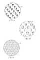
- FIG. 1 ais a plan view of a sheet of medium made in accordance with the present invention containing identification images of unique indicia;
- FIGS. 1 b , 1 c , 1 d , and 1 eare an enlarged partial view of a portion of the sheet of medium of FIG. 1 illustrating a variety of identification images;
- FIG. 2 ais a perspective view of a medium having identification indicia of FIGS. 1 a and 1 b;
- FIG. 2 bis a cross-sectional view of the medium of FIG. 2 a illustrating the peel able nature of the invention
- FIG. 2 cis a cross-sectional view of another modified medium made in accordance with the present invention.
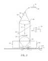
- FIG. 3is a schematic view of an apparatus for printing the various indicia on the media of FIG. 1 b using near-field optics;
- FIG. 4is a flow chart illustrating the method for making the media of FIG. 1 a;
- FIG. 5 ais a schematic view of the grinding of the media of FIG. 1 a for making discrete identification particles
- FIG. 5 bis an enlarged view of a micron-sized particle of FIG. 5 a , imprinted with an image;
- FIG. 5 crepresents an alphanumeric pattern
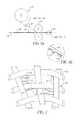
- FIG. 6 ais a schematic view illustrating a method transferring the micron-sized particle to an article
- FIG. 6 bis an enlarged partial view of a the micron-sized particle of FIG. 6 a;
- FIG. 7is an enlarged view illustrating the identification particles adhered to the fibers of the article of FIG. 6 a;
- FIG. 8is a schematic view of an apparatus used for detecting the identification particles located on the article described in FIG. 7 ;
- FIG. 9 ais a schematic view of an apparatus used for viewing the identification particles located on the article described in FIG. 7 ;
- FIG. 9 bis an enlarged partial view of the image displayed by the apparatus used for viewing the identification particles located on the article described in FIG. 7 ;
- FIG. 10 ais an illustration of a monotone image
- FIG. 10 bis an illustration of a continuous tone image
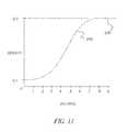
- FIG. 11is a graph illustrating the densities of the images of FIG. 10 a and FIG. 10 b.
- the methodcomprises creation of a discrete continuous tone image using near-field optics.
- the methodalso comprises creation of a discrete identification indicia (image) using near-field optics by imaging a plurality of unique indicia onto a medium.
- the mediumis ground to form discrete identification particles.
- the size of each identification particlebeing 2 to 20 microns contains the indicia or a portion of the indicia.
- the particles having the indiciaare applied to an article.
- the method of identifyingincludes scanning or optically viewing the article and viewing the identification particles imprinted with the indicia.
- the identification indiciamay be used for a variety of purposes.
- the identification indiciacan be used to identify a property or characteristic of the article upon which they are placed.
- the identification indicia partsare well suited for authentication of the article.
- the articleis genuine and/or comes from a particular source.
- FIG. 1 athere is illustrated a plan view of a sheet of medium 5 containing a plurality of identification images of indicia 10 shown in an enlarged plan view in FIG 1 b .
- the length “d” of the indicia (image) 10is no greater than 10 microns.
- the indicia 10can be of such a size that can be read when placed on the article but not detract from the original appearance of the article on which it is placed as viewed under normal viewing conditions.
- a plurality of identification imagesare imaged onto the media 5 using near-field optics, which will be explained later in FIG. 3 .
- the indicia 10can be an alphanumeric 30 , a continuous tone image of a person 32 , place or thing 34 , or a continuous tone image of a characteristic 36 of the article such as texture as shown in FIGS. 1 b , 1 c , 1 d , and 1 e respectively. If an alphanumeric is used as the micro image, this can also be used as a serial number and/or code for use in further authenticating the article or providing additional information directly from the alphanumeric or be used to look up information from a database.
- the medium 5comprises a support layer 12 .
- the support layer 12is polyester, for example Estar, and has a thickness of approximately 1 mil (0.025 mm.).
- a release layer 14such as hydroxyethylcellulous and polyvinyl butyral and has a thickness of approximately 0.5 to 1.0 microns (0.0005 mm to 0.001 mm).
- the imaging layer 16can be coated directly onto the support layer 12 .
- the imaging layer 16is a dye, for example, metallized phthalocyanine and has a thickness of approximately 100-1000 nanometers (0.0001 mm to 0.001 mm).
- FIG. 2 bthere is illustrated a cross-sectional view of the medium 5 .
- the use of the release layer 14allows the imaging layer 16 to be peeled from the support layer 12 .
- the support layer 12is a rigid plastic, for example polycarbonate
- separating the imaging layer 16 from the support layeris advantageous for producing small particle sizes as discussed later on.
- the support layer 12is a flexible material such as Estar or acetate the imaging layer 16 does not need to be separated from the support layer 12 .
- a modified medium 18made in accordance with the present invention.
- Medium 18is similar to medium 5 , like numerals indicating like elements and function.
- a clear protective layer 20is applied over the imaging layer 16 to protect the imaging layer 16 from dirt, dust, and scratches.
- the protective layer 20can be applied at manufacture and removed prior to the printing process and then reapplied after the printing process.
- the protective layer 20for example can be a thin Mylar of approximately 1 micron or less thickness or can be a clear toner applied after the printing process.
- FIG. 3there is illustrated an apparatus 50 for forming indicia 10 on medium 5 or 18 .
- the object 51is a macroscopic representation of the indicia 30 to be formed on medium 5 or 18 .
- An image 61is created in the imaging layer 16 by transferring light from the object 51 .
- the light beam 49 from a light source 53reflects from a beam splitter 55 , through a lens system 62 , reflects off the object 51 and passes through an objective lens 54 of conventional design and impinges onto a solid immersion lens (SIL) 56 .
- SILsolid immersion lens
- the medium 5 or 18 resting on a stage 57is placed within a critical distance f; images formed from such a system will have a lateral spatial resolution that exceeds the diffraction limit as is well known to those skilled in the art.
- the light beam 52passes through an objective lens 54 of conventional design and impinges onto a solid immersion lens (SIL) 56 .
- the SIL 56is positioned within the near-field coupling limit appropriate for the particular lens in use by the use of a positioning device 58 .
- the image 61 used to form the identification indicia 10can be obtained from a variety of sources 59 such as an illuminated object, a negative, print, and/or a softcopy display.
- the image 61can be black and white or color.
- the softcopy displaycan be a CRT, OLED or other similar type device.
- the present embodimentdescribes a plurality of the same image formed on the sheet of medium 5 .
- a plurality of images each image being a different imageare formed on the sheet of medium 5 .
- the size of the indicia images formedare on the order of 1 to 10 microns the density of the number of images formed in a very small area is greatly increased.
- the size of the image being formeddepends on the resolution and the size of the original to be produced. For example a 4 R photographic print (4 inches by 6 inches) can be reduced using near-field optical imaging to an image, which is approximately 0.01 mm by 0.015 mm.
- the methodcomprises creation of a digital file of the characteristic 36 image to form the indicia 30 at step 100 .
- the image of the indicia 30is repeatedly printed onto the medium 5 at step 110 .
- the medium 5is then processed at step 120 .
- the medium 5 with the image of the indicia 30is ground ( FIG. 5 a ) to form micro discrete identification micro particles 40 at step 130 shown in FIG. 5 b .
- the micron-sized identification micro particles 40 containing the image of the indicia 30 or a portion of the image of the indiciaare then transferred to the article 48 at step 140 as described in FIGS. 6 a and 6 b.
- each identification particle 40contains at least one image of the indicia 30 or a portion of the indicia 30 , as shown in FIG 5 b . Since a large number of identification particles 40 are transferred to the article 48 , the image of the indicia 30 and/or portions of the image of the indicia 30 ensure the complete indicia will be discernable. Now referring to FIG.
- the indicium 30is printed on the media 5 in a repeating pattern 31 .
- the length “x” of the printed pattern 31 of the indicia 30is no greater than 10 microns or the size of the identification particle 40 .
- the length “x”corresponds to the size of the identification particles 40 such that all or a portion of the indicia 30 appears on one or more surfaces of the particle.
- the article 48is currency.
- article 48may be any desired object, for example stock certificates, tickets, clothing, stamps, labels, etc.
- the identification particles 40are conveyed on a belt 42 via a transport device 44 .
- the articles 48are conveyed on a belt 46 via a transportation device not shown.
- the belts 42 and 46convey the identification particles 40 and the article 48 respectively through a pair of transfer rollers 47 where the micron-sized identification particles 40 are transferred from the belt 44 to the article 48 .
- the number of particles transferred to the article 48is such that all or a portion of the indicia 30 appears on one or more particles so the entire indicium 30 can readily be identified.
- the method of transfercan be an electrostatic process similar to the manner toner particles are applied to paper.
- FIG. 6 bis an enlarged partial view of the belt 44 and the micron-sized identification micro particles 40 shown in FIG. 6 a .
- Other methods of transferring the micron-sized identification micro particles 40are: creating a slurry and coating the slurry on the article, creating a tape and transferring the micron-sized identification particles 40 using pressure rollers and direct contact, and sprinkling the micron-sized identification micro particles 40 onto the article, or applying an adhesive on the article or the particles. All that is required is that the particles adhere in some manner to the article.
- the identification particles 40can be detected by scanning or optically viewing the article 48 and discerning the micron-sized identification particles 40 shown in FIG. 5 b containing the indicia 30 .
- the medium 5 shown in FIGS. 1 a and 1 bcan include a material such as a fluorescent polymer; for example doped Poly(phenylene vinylene) (PPV) or polyethylene naphthalate (PEN) that fluoresces under certain lighting conditions.
- the fluorescent materialmakes it easier to detect whether the micron-sized identification particles 40 have been applied to the article 48 .
- the micron-sized authentication particles 40fluoresce providing a signal 72 to a detector 74 that indicates the article 48 has been impregnated with the authentication particles 40 .
- the authentication particles 40 on the article 48can be viewed using magnifying imaging device 80 to capture an image of the indicia 30 .
- the light beam 82 from a light source 84reflects from a beam splitter 86 and passes through an objective lens 88 of conventional design and impinges onto a solid immersion lens (SIL) 90 .
- SILsolid immersion lens
- Article 48 resting on a stage 92is placed within a critical distance f; images formed from such a system will have a lateral spatial resolution that exceeds the diffraction limit as is well known to those skilled in the art.
- the SIL 90is positioned within the near-field coupling limit appropriate for the particular lens in use by the use of a positioning device 94 .
- Such a positioning devicecould be a flying head as is used in hard disk storage devices.
- the light beam 82is reflected from the article 48 , passes through the SIL 90 , the objective lens 88 , and the beam splitter 86 , imaging the authentication particles 40 containing the indicia 30 onto a sensor 96 by a lens system 98 .
- FIG. 9 ban enlarged partial view of the image captured by the device 80 is shown.
- the image of the authentication particles 40 containing indicia 30 on the article 48are displayed for viewing for authentication purposes.
- the size of the identification particles 40are such that all or a portion of the indicia 30 appears on one or more surfaces of the particle.
- the identification particles 40 applied to the article 48are of a size such that they are not visually discernable on the article 48 with the unaided eye under normal viewing conditions or detract from the overall original appearance of the article 48 .
- the sizeis preferably no greater than about 20 microns, and is generally in the range of about 2 to 20 microns.
- the providing of identification particles on products made in accordance with the present inventionprovides a method for allowing independent verification of the authenticity of a product directly from the product, and also provides a mechanism for preventing and/or minimizing counterfeiting of such products.
- the inventionhas been described in detail with particular reference to certain preferred embodiments thereof, but it will be understood that variations and modifications can be effected within the spirit and scope of the invention.
- a monotone image 200 having a single uniform density of 2.0 measured at nine discrete pointsis illustrated.
- the density of the monotone image 200does not vary and is the same over the entire image.
- the density of an imagecan be measured by those of ordinary skill in the art using a reflection densitometer such as an X-Rite 310 Photographic Densitometer.
- a continuous tone imagehaving a density range between 0.1 and 2.0 density measured at nine discrete point, as indicated by numerals 1 through 9.
- the density of the continuous tone image 220changes over the entire image.
- the density of an imagecan be measured by those of ordinary skill in the art using a reflection densitometer such as an X-Rite 310 Photographic Densitometer.
- FIG. 11illustrates the graphs 230 and 240 of the densities of the monotone image 200 and the continuous tone image 220 respectively measured at nine discrete points.
Landscapes
- Business, Economics & Management (AREA)
- Accounting & Taxation (AREA)
- Finance (AREA)
- Physics & Mathematics (AREA)
- General Physics & Mathematics (AREA)
- Engineering & Computer Science (AREA)
- Theoretical Computer Science (AREA)
- Credit Cards Or The Like (AREA)
Abstract
Description
- 5 medium sheet
- 10 indicia
- 12 support layer
- 14 release layer
- 16 imaging layer
- 18 medium
- 20 protective layer
- 30 alphanumeric
- 31 pattern
- 32 person
- 34 place/thing
- 36 characteristic
- 38 grinding device
- 40 identification particles
- 42 belt
- 44 transport device
- 46 belt
- 47 transfer rollers
- 48 article
- 49 light beam
- 50 apparatus
- 51 object
- 52 light beam
- 53 light source
- 54 objective lens
- 55 beam splitter
- 56 solid immersion lens (SIL)
- 57 stage
- 58 positioning device
- 59 source
- 60 fibers
- 70 light source
- 71 transport mechanism
- 72 signal
- 74 detector
- 80 imaging device
- 82 light beam
- 84 light source
- 86 beam splitter
- 88 objective lens
- 90 solid immersion lens (SIL)
- 92 stage
- 94 positioning device
- 96 sensor
- 98 lens system
- 100 step
- 110 step
- 120 step
- 130 step
- 140 step
- 200 monotone image
- 210 continuous tone image
- 220 graph
- 230 graph
Claims (5)
Priority Applications (1)
| Application Number | Priority Date | Filing Date | Title |
|---|---|---|---|
| US09/957,011US8403367B2 (en) | 2001-08-02 | 2001-09-20 | Authentication using near-field optical imaging |
Applications Claiming Priority (2)
| Application Number | Priority Date | Filing Date | Title |
|---|---|---|---|
| US09/920,972US6722699B2 (en) | 2001-08-02 | 2001-08-02 | Authentication using near-field optical imaging |
| US09/957,011US8403367B2 (en) | 2001-08-02 | 2001-09-20 | Authentication using near-field optical imaging |
Related Parent Applications (1)
| Application Number | Title | Priority Date | Filing Date |
|---|---|---|---|
| US09/920,972Continuation-In-PartUS6722699B2 (en) | 2001-08-02 | 2001-08-02 | Authentication using near-field optical imaging |
Publications (2)
| Publication Number | Publication Date |
|---|---|
| US20030025319A1 US20030025319A1 (en) | 2003-02-06 |
| US8403367B2true US8403367B2 (en) | 2013-03-26 |
Family
ID=46280091
Family Applications (1)
| Application Number | Title | Priority Date | Filing Date |
|---|---|---|---|
| US09/957,011Expired - Fee RelatedUS8403367B2 (en) | 2001-08-02 | 2001-09-20 | Authentication using near-field optical imaging |
Country Status (1)
| Country | Link |
|---|---|
| US (1) | US8403367B2 (en) |
Cited By (3)
| Publication number | Priority date | Publication date | Assignee | Title |
|---|---|---|---|---|
| US9811671B1 (en) | 2000-05-24 | 2017-11-07 | Copilot Ventures Fund Iii Llc | Authentication method and system |
| US9846814B1 (en) | 2008-04-23 | 2017-12-19 | Copilot Ventures Fund Iii Llc | Authentication method and system |
| US9844970B2 (en)* | 2012-12-10 | 2017-12-19 | Gemalto Sa | Secure laser marking personalisation |
Families Citing this family (1)
| Publication number | Priority date | Publication date | Assignee | Title |
|---|---|---|---|---|
| DE102005061749A1 (en)* | 2005-12-21 | 2007-07-05 | Giesecke & Devrient Gmbh | Optically variable security element for making valuable objects safe has an achromatic reflecting micro-structure taking the form of a mosaic made from achromatic reflecting mosaic elements |
Citations (19)
| Publication number | Priority date | Publication date | Assignee | Title |
|---|---|---|---|---|
| US4081828A (en)* | 1976-03-15 | 1978-03-28 | Geosource, Inc. | Method for halftone reproduction of continuous tone images |
| US4186943A (en) | 1976-09-24 | 1980-02-05 | The Governor And Company Of The Bank Of England | Security devices |
| US4634220A (en) | 1983-02-07 | 1987-01-06 | Minnesota Mining And Manufacturing Company | Directionally imaged sheeting |
| US5126256A (en) | 1987-04-08 | 1992-06-30 | Merck Patent Gesellschaft Mit Beschrankter Haftung | Process for the preparation of glucose dehydrogenase from bacillus megaterium |
| US5139812A (en) | 1989-07-07 | 1992-08-18 | Bioprobe Systems | Method and apparatus for high security crypto-marking for protecting valuable objects |
| US5262981A (en)* | 1990-07-03 | 1993-11-16 | Basf Aktiengesellschaft | Storage of information units in the nanometer range |
| US5272330A (en) | 1990-11-19 | 1993-12-21 | At&T Bell Laboratories | Near field scanning optical microscope having a tapered waveguide |
| US5429392A (en)* | 1993-06-18 | 1995-07-04 | Loving; Charles D. | Composite microdot and method |
| US5500331A (en) | 1994-05-25 | 1996-03-19 | Eastman Kodak Company | Comminution with small particle milling media |
| US5662279A (en) | 1995-12-05 | 1997-09-02 | Eastman Kodak Company | Process for milling and media separation |
| US5718388A (en) | 1994-05-25 | 1998-02-17 | Eastman Kodak | Continuous method of grinding pharmaceutical substances |
| US5793743A (en)* | 1993-11-03 | 1998-08-11 | International Business Machines Corporation | Reading a magnetic storage medium with a probe that detects tunneling current induced in a magnetic layer by a non-ionizing light beam |
| US5904375A (en)* | 1995-08-01 | 1999-05-18 | Brugada; Jorge C.B. | Security support with an imprinted micropattern contained therein which prevents falsification of documents when high-resolution copier machines are used |
| US5974150A (en) | 1997-09-30 | 1999-10-26 | Tracer Detection Technology Corp. | System and method for authentication of goods |
| US6034348A (en)* | 1996-12-18 | 2000-03-07 | Electronics And Telecommunications Research Institute | Micro etching system using laser ablation |
| US6155605A (en)* | 1996-04-15 | 2000-12-05 | De La Rue International Limited | Document of value |
| US6195452B1 (en) | 1998-04-27 | 2001-02-27 | George R. Royer | Method of authenticating negotiable instruments |
| US6396789B1 (en)* | 1998-02-27 | 2002-05-28 | Calimetrics, Inc. | Data storage system and methods using diffractive near-field optics |
| US6497996B1 (en)* | 1999-04-30 | 2002-12-24 | Fuji Photo Film Co., Ltd. | Fine pattern forming method |
- 2001
- 2001-09-20USUS09/957,011patent/US8403367B2/ennot_activeExpired - Fee Related
Patent Citations (19)
| Publication number | Priority date | Publication date | Assignee | Title |
|---|---|---|---|---|
| US4081828A (en)* | 1976-03-15 | 1978-03-28 | Geosource, Inc. | Method for halftone reproduction of continuous tone images |
| US4186943A (en) | 1976-09-24 | 1980-02-05 | The Governor And Company Of The Bank Of England | Security devices |
| US4634220A (en) | 1983-02-07 | 1987-01-06 | Minnesota Mining And Manufacturing Company | Directionally imaged sheeting |
| US5126256A (en) | 1987-04-08 | 1992-06-30 | Merck Patent Gesellschaft Mit Beschrankter Haftung | Process for the preparation of glucose dehydrogenase from bacillus megaterium |
| US5139812A (en) | 1989-07-07 | 1992-08-18 | Bioprobe Systems | Method and apparatus for high security crypto-marking for protecting valuable objects |
| US5262981A (en)* | 1990-07-03 | 1993-11-16 | Basf Aktiengesellschaft | Storage of information units in the nanometer range |
| US5272330A (en) | 1990-11-19 | 1993-12-21 | At&T Bell Laboratories | Near field scanning optical microscope having a tapered waveguide |
| US5429392A (en)* | 1993-06-18 | 1995-07-04 | Loving; Charles D. | Composite microdot and method |
| US5793743A (en)* | 1993-11-03 | 1998-08-11 | International Business Machines Corporation | Reading a magnetic storage medium with a probe that detects tunneling current induced in a magnetic layer by a non-ionizing light beam |
| US5500331A (en) | 1994-05-25 | 1996-03-19 | Eastman Kodak Company | Comminution with small particle milling media |
| US5718388A (en) | 1994-05-25 | 1998-02-17 | Eastman Kodak | Continuous method of grinding pharmaceutical substances |
| US5904375A (en)* | 1995-08-01 | 1999-05-18 | Brugada; Jorge C.B. | Security support with an imprinted micropattern contained therein which prevents falsification of documents when high-resolution copier machines are used |
| US5662279A (en) | 1995-12-05 | 1997-09-02 | Eastman Kodak Company | Process for milling and media separation |
| US6155605A (en)* | 1996-04-15 | 2000-12-05 | De La Rue International Limited | Document of value |
| US6034348A (en)* | 1996-12-18 | 2000-03-07 | Electronics And Telecommunications Research Institute | Micro etching system using laser ablation |
| US5974150A (en) | 1997-09-30 | 1999-10-26 | Tracer Detection Technology Corp. | System and method for authentication of goods |
| US6396789B1 (en)* | 1998-02-27 | 2002-05-28 | Calimetrics, Inc. | Data storage system and methods using diffractive near-field optics |
| US6195452B1 (en) | 1998-04-27 | 2001-02-27 | George R. Royer | Method of authenticating negotiable instruments |
| US6497996B1 (en)* | 1999-04-30 | 2002-12-24 | Fuji Photo Film Co., Ltd. | Fine pattern forming method |
Non-Patent Citations (1)
| Title |
|---|
| "Imaging with Solid Immersion Lenses, Spatial Resolution, and Applications", Qiang Wu, Luke P. Ghislain, V. B. Elings, Proceedings of the IEEE, vol. 88, No. 9, Sep. 2000, pp. 1491-1498. |
Cited By (8)
| Publication number | Priority date | Publication date | Assignee | Title |
|---|---|---|---|---|
| US9811671B1 (en) | 2000-05-24 | 2017-11-07 | Copilot Ventures Fund Iii Llc | Authentication method and system |
| US9846814B1 (en) | 2008-04-23 | 2017-12-19 | Copilot Ventures Fund Iii Llc | Authentication method and system |
| US10275675B1 (en) | 2008-04-23 | 2019-04-30 | Copilot Ventures Fund Iii Llc | Authentication method and system |
| US11200439B1 (en) | 2008-04-23 | 2021-12-14 | Copilot Ventures Fund Iii Llc | Authentication method and system |
| US11600056B2 (en) | 2008-04-23 | 2023-03-07 | CoPilot Ventures III LLC | Authentication method and system |
| US11924356B2 (en) | 2008-04-23 | 2024-03-05 | Copilot Ventures Fund Iii Llc | Authentication method and system |
| US12212690B2 (en) | 2008-04-23 | 2025-01-28 | Copilot Ventures Fund Iii Llc | Authentication method and system |
| US9844970B2 (en)* | 2012-12-10 | 2017-12-19 | Gemalto Sa | Secure laser marking personalisation |
Also Published As
| Publication number | Publication date |
|---|---|
| US20030025319A1 (en) | 2003-02-06 |
Similar Documents
| Publication | Publication Date | Title |
|---|---|---|
| US6722699B2 (en) | Authentication using near-field optical imaging | |
| AU774091B2 (en) | Genuine/counterfeit discriminating method, genuine/counterfeit discrimination object, and genuine/counterfeit discriminating device | |
| KR101355389B1 (en) | Method of marking a document or item; method and device for identifying the marked document or item; use of circular polarizing particles | |
| US5325167A (en) | Record document authentication by microscopic grain structure and method | |
| KR940008669B1 (en) | Transparent sheet containing directional image information and producing method thereof | |
| US20060196945A1 (en) | Identification device, anti-counterfeiting apparatus and method | |
| US7063924B2 (en) | Security device with patterned metallic reflection | |
| EP0974138A1 (en) | Identification label and method of labelling an object | |
| JPH08300801A (en) | Method for transferring secret protection element to base layer and document having secret protection element | |
| CN1350274A (en) | Anticounterfeit mark comprising a plurality of small signs and method for forming the same | |
| WO2004063978A1 (en) | Laminated material with imprinted information, article on which the same is attached, method for reading information code | |
| US8403367B2 (en) | Authentication using near-field optical imaging | |
| JP5321804B2 (en) | Diffraction grating | |
| JP2822826B2 (en) | Transparent protective seal with hologram | |
| JPH09272255A (en) | Medium for indicating image and method for forming image | |
| US6268899B1 (en) | Identification of lenticular material characteristics in lenticular printers | |
| JP4391081B2 (en) | Thermal printing recording medium, commuter pass, and manufacturing method thereof | |
| US7294446B2 (en) | Digital analog recording using near field optical imaging | |
| JP5589268B2 (en) | Relief type diffraction grating or hologram | |
| JPH0243097A (en) | Reduced image transfer material | |
| US20040137376A1 (en) | Method and system for replicating film data to a metal substrate and article of manufacture | |
| JPH06297891A (en) | Optical path control body, manufacturing method and use method thereof, information recording medium using optical path control body, transfer sheet, printed matter, manufacturing method thereof, and forgery discrimination method | |
| JPH05345493A (en) | Method and apparatus for manufacturing information recording medium | |
| CN1250201A (en) | Grating fingerprint anti-counterfeiting mark | |
| JPH02266996A (en) | Certificate identification card with copied fine pattern |
Legal Events
| Date | Code | Title | Description |
|---|---|---|---|
| AS | Assignment | Owner name:EASTMAN KODAK COMPANY, NEW YORK Free format text:ASSIGNMENT OF ASSIGNORS INTEREST;ASSIGNORS:PATTON, DAVID L.;SPOONHOWER, JOHN P.;REEL/FRAME:012195/0778;SIGNING DATES FROM 20010914 TO 20010917 Owner name:EASTMAN KODAK COMPANY, NEW YORK Free format text:ASSIGNMENT OF ASSIGNORS INTEREST;ASSIGNORS:PATTON, DAVID L.;SPOONHOWER, JOHN P.;SIGNING DATES FROM 20010914 TO 20010917;REEL/FRAME:012195/0778 | |
| AS | Assignment | Owner name:CITICORP NORTH AMERICA, INC., AS AGENT, NEW YORK Free format text:SECURITY INTEREST;ASSIGNORS:EASTMAN KODAK COMPANY;PAKON, INC.;REEL/FRAME:028201/0420 Effective date:20120215 | |
| FEPP | Fee payment procedure | Free format text:PAYOR NUMBER ASSIGNED (ORIGINAL EVENT CODE: ASPN); ENTITY STATUS OF PATENT OWNER: LARGE ENTITY | |
| STCF | Information on status: patent grant | Free format text:PATENTED CASE | |
| AS | Assignment | Owner name:WILMINGTON TRUST, NATIONAL ASSOCIATION, AS AGENT, Free format text:PATENT SECURITY AGREEMENT;ASSIGNORS:EASTMAN KODAK COMPANY;PAKON, INC.;REEL/FRAME:030122/0235 Effective date:20130322 Owner name:WILMINGTON TRUST, NATIONAL ASSOCIATION, AS AGENT, MINNESOTA Free format text:PATENT SECURITY AGREEMENT;ASSIGNORS:EASTMAN KODAK COMPANY;PAKON, INC.;REEL/FRAME:030122/0235 Effective date:20130322 | |
| AS | Assignment | Owner name:PAKON, INC., NEW YORK Free format text:RELEASE OF SECURITY INTEREST IN PATENTS;ASSIGNORS:CITICORP NORTH AMERICA, INC., AS SENIOR DIP AGENT;WILMINGTON TRUST, NATIONAL ASSOCIATION, AS JUNIOR DIP AGENT;REEL/FRAME:031157/0451 Effective date:20130903 Owner name:BANK OF AMERICA N.A., AS AGENT, MASSACHUSETTS Free format text:INTELLECTUAL PROPERTY SECURITY AGREEMENT (ABL);ASSIGNORS:EASTMAN KODAK COMPANY;FAR EAST DEVELOPMENT LTD.;FPC INC.;AND OTHERS;REEL/FRAME:031162/0117 Effective date:20130903 Owner name:JPMORGAN CHASE BANK, N.A., AS ADMINISTRATIVE, DELAWARE Free format text:INTELLECTUAL PROPERTY SECURITY AGREEMENT (FIRST LIEN);ASSIGNORS:EASTMAN KODAK COMPANY;FAR EAST DEVELOPMENT LTD.;FPC INC.;AND OTHERS;REEL/FRAME:031158/0001 Effective date:20130903 Owner name:BARCLAYS BANK PLC, AS ADMINISTRATIVE AGENT, NEW YORK Free format text:INTELLECTUAL PROPERTY SECURITY AGREEMENT (SECOND LIEN);ASSIGNORS:EASTMAN KODAK COMPANY;FAR EAST DEVELOPMENT LTD.;FPC INC.;AND OTHERS;REEL/FRAME:031159/0001 Effective date:20130903 Owner name:EASTMAN KODAK COMPANY, NEW YORK Free format text:RELEASE OF SECURITY INTEREST IN PATENTS;ASSIGNORS:CITICORP NORTH AMERICA, INC., AS SENIOR DIP AGENT;WILMINGTON TRUST, NATIONAL ASSOCIATION, AS JUNIOR DIP AGENT;REEL/FRAME:031157/0451 Effective date:20130903 Owner name:JPMORGAN CHASE BANK, N.A., AS ADMINISTRATIVE, DELA Free format text:INTELLECTUAL PROPERTY SECURITY AGREEMENT (FIRST LIEN);ASSIGNORS:EASTMAN KODAK COMPANY;FAR EAST DEVELOPMENT LTD.;FPC INC.;AND OTHERS;REEL/FRAME:031158/0001 Effective date:20130903 Owner name:BARCLAYS BANK PLC, AS ADMINISTRATIVE AGENT, NEW YO Free format text:INTELLECTUAL PROPERTY SECURITY AGREEMENT (SECOND LIEN);ASSIGNORS:EASTMAN KODAK COMPANY;FAR EAST DEVELOPMENT LTD.;FPC INC.;AND OTHERS;REEL/FRAME:031159/0001 Effective date:20130903 | |
| FPAY | Fee payment | Year of fee payment:4 | |
| AS | Assignment | Owner name:KODAK IMAGING NETWORK, INC., NEW YORK Free format text:RELEASE BY SECURED PARTY;ASSIGNOR:JP MORGAN CHASE BANK, N.A., AS ADMINISTRATIVE AGENT;REEL/FRAME:049814/0001 Effective date:20190617 Owner name:PAKON, INC., NEW YORK Free format text:RELEASE BY SECURED PARTY;ASSIGNOR:JP MORGAN CHASE BANK, N.A., AS ADMINISTRATIVE AGENT;REEL/FRAME:049814/0001 Effective date:20190617 Owner name:QUALEX, INC., NEW YORK Free format text:RELEASE BY SECURED PARTY;ASSIGNOR:JP MORGAN CHASE BANK, N.A., AS ADMINISTRATIVE AGENT;REEL/FRAME:049814/0001 Effective date:20190617 Owner name:KODAK AVIATION LEASING LLC, NEW YORK Free format text:RELEASE BY SECURED PARTY;ASSIGNOR:JP MORGAN CHASE BANK, N.A., AS ADMINISTRATIVE AGENT;REEL/FRAME:049814/0001 Effective date:20190617 Owner name:FPC, INC., NEW YORK Free format text:RELEASE BY SECURED PARTY;ASSIGNOR:JP MORGAN CHASE BANK, N.A., AS ADMINISTRATIVE AGENT;REEL/FRAME:049814/0001 Effective date:20190617 Owner name:FAR EAST DEVELOPMENT LTD., NEW YORK Free format text:RELEASE BY SECURED PARTY;ASSIGNOR:JP MORGAN CHASE BANK, N.A., AS ADMINISTRATIVE AGENT;REEL/FRAME:049814/0001 Effective date:20190617 Owner name:KODAK AMERICAS, LTD., NEW YORK Free format text:RELEASE BY SECURED PARTY;ASSIGNOR:JP MORGAN CHASE BANK, N.A., AS ADMINISTRATIVE AGENT;REEL/FRAME:049814/0001 Effective date:20190617 Owner name:KODAK PHILIPPINES, LTD., NEW YORK Free format text:RELEASE BY SECURED PARTY;ASSIGNOR:JP MORGAN CHASE BANK, N.A., AS ADMINISTRATIVE AGENT;REEL/FRAME:049814/0001 Effective date:20190617 Owner name:CREO MANUFACTURING AMERICA LLC, NEW YORK Free format text:RELEASE BY SECURED PARTY;ASSIGNOR:JP MORGAN CHASE BANK, N.A., AS ADMINISTRATIVE AGENT;REEL/FRAME:049814/0001 Effective date:20190617 Owner name:LASER PACIFIC MEDIA CORPORATION, NEW YORK Free format text:RELEASE BY SECURED PARTY;ASSIGNOR:JP MORGAN CHASE BANK, N.A., AS ADMINISTRATIVE AGENT;REEL/FRAME:049814/0001 Effective date:20190617 Owner name:NPEC, INC., NEW YORK Free format text:RELEASE BY SECURED PARTY;ASSIGNOR:JP MORGAN CHASE BANK, N.A., AS ADMINISTRATIVE AGENT;REEL/FRAME:049814/0001 Effective date:20190617 Owner name:KODAK PORTUGUESA LIMITED, NEW YORK Free format text:RELEASE BY SECURED PARTY;ASSIGNOR:JP MORGAN CHASE BANK, N.A., AS ADMINISTRATIVE AGENT;REEL/FRAME:049814/0001 Effective date:20190617 Owner name:KODAK REALTY, INC., NEW YORK Free format text:RELEASE BY SECURED PARTY;ASSIGNOR:JP MORGAN CHASE BANK, N.A., AS ADMINISTRATIVE AGENT;REEL/FRAME:049814/0001 Effective date:20190617 Owner name:EASTMAN KODAK COMPANY, NEW YORK Free format text:RELEASE BY SECURED PARTY;ASSIGNOR:JP MORGAN CHASE BANK, N.A., AS ADMINISTRATIVE AGENT;REEL/FRAME:049814/0001 Effective date:20190617 Owner name:KODAK (NEAR EAST), INC., NEW YORK Free format text:RELEASE BY SECURED PARTY;ASSIGNOR:JP MORGAN CHASE BANK, N.A., AS ADMINISTRATIVE AGENT;REEL/FRAME:049814/0001 Effective date:20190617 | |
| AS | Assignment | Owner name:FAR EAST DEVELOPMENT LTD., NEW YORK Free format text:RELEASE BY SECURED PARTY;ASSIGNOR:BARCLAYS BANK PLC;REEL/FRAME:052773/0001 Effective date:20170202 Owner name:NPEC INC., NEW YORK Free format text:RELEASE BY SECURED PARTY;ASSIGNOR:BARCLAYS BANK PLC;REEL/FRAME:052773/0001 Effective date:20170202 Owner name:KODAK PHILIPPINES LTD., NEW YORK Free format text:RELEASE BY SECURED PARTY;ASSIGNOR:BARCLAYS BANK PLC;REEL/FRAME:052773/0001 Effective date:20170202 Owner name:FPC INC., NEW YORK Free format text:RELEASE BY SECURED PARTY;ASSIGNOR:BARCLAYS BANK PLC;REEL/FRAME:052773/0001 Effective date:20170202 Owner name:KODAK (NEAR EAST) INC., NEW YORK Free format text:RELEASE BY SECURED PARTY;ASSIGNOR:BARCLAYS BANK PLC;REEL/FRAME:052773/0001 Effective date:20170202 Owner name:KODAK AMERICAS LTD., NEW YORK Free format text:RELEASE BY SECURED PARTY;ASSIGNOR:BARCLAYS BANK PLC;REEL/FRAME:052773/0001 Effective date:20170202 Owner name:EASTMAN KODAK COMPANY, NEW YORK Free format text:RELEASE BY SECURED PARTY;ASSIGNOR:BARCLAYS BANK PLC;REEL/FRAME:052773/0001 Effective date:20170202 Owner name:LASER PACIFIC MEDIA CORPORATION, NEW YORK Free format text:RELEASE BY SECURED PARTY;ASSIGNOR:BARCLAYS BANK PLC;REEL/FRAME:052773/0001 Effective date:20170202 Owner name:QUALEX INC., NEW YORK Free format text:RELEASE BY SECURED PARTY;ASSIGNOR:BARCLAYS BANK PLC;REEL/FRAME:052773/0001 Effective date:20170202 Owner name:KODAK REALTY INC., NEW YORK Free format text:RELEASE BY SECURED PARTY;ASSIGNOR:BARCLAYS BANK PLC;REEL/FRAME:052773/0001 Effective date:20170202 | |
| FEPP | Fee payment procedure | Free format text:MAINTENANCE FEE REMINDER MAILED (ORIGINAL EVENT CODE: REM.); ENTITY STATUS OF PATENT OWNER: LARGE ENTITY | |
| LAPS | Lapse for failure to pay maintenance fees | Free format text:PATENT EXPIRED FOR FAILURE TO PAY MAINTENANCE FEES (ORIGINAL EVENT CODE: EXP.); ENTITY STATUS OF PATENT OWNER: LARGE ENTITY | |
| STCH | Information on status: patent discontinuation | Free format text:PATENT EXPIRED DUE TO NONPAYMENT OF MAINTENANCE FEES UNDER 37 CFR 1.362 | |
| FP | Lapsed due to failure to pay maintenance fee | Effective date:20210326 |