US8403150B2 - End-cap assembly with pump hose for a filter and filter comprising such an end-cap assembly - Google Patents
End-cap assembly with pump hose for a filter and filter comprising such an end-cap assemblyDownload PDFInfo
- Publication number
- US8403150B2 US8403150B2US11/379,725US37972506AUS8403150B2US 8403150 B2US8403150 B2US 8403150B2US 37972506 AUS37972506 AUS 37972506AUS 8403150 B2US8403150 B2US 8403150B2
- Authority
- US
- United States
- Prior art keywords
- pump hose
- holder
- cap
- inlet port
- cap assembly
- Prior art date
- Legal status (The legal status is an assumption and is not a legal conclusion. Google has not performed a legal analysis and makes no representation as to the accuracy of the status listed.)
- Active, expires
Links
Images


Classifications
- B—PERFORMING OPERATIONS; TRANSPORTING
- B01—PHYSICAL OR CHEMICAL PROCESSES OR APPARATUS IN GENERAL
- B01D—SEPARATION
- B01D65/00—Accessories or auxiliary operations, in general, for separation processes or apparatus using semi-permeable membranes
- A—HUMAN NECESSITIES
- A61—MEDICAL OR VETERINARY SCIENCE; HYGIENE
- A61M—DEVICES FOR INTRODUCING MEDIA INTO, OR ONTO, THE BODY; DEVICES FOR TRANSDUCING BODY MEDIA OR FOR TAKING MEDIA FROM THE BODY; DEVICES FOR PRODUCING OR ENDING SLEEP OR STUPOR
- A61M1/00—Suction or pumping devices for medical purposes; Devices for carrying-off, for treatment of, or for carrying-over, body-liquids; Drainage systems
- A61M1/14—Dialysis systems; Artificial kidneys; Blood oxygenators ; Reciprocating systems for treatment of body fluids, e.g. single needle systems for hemofiltration or pheresis
- A61M1/16—Dialysis systems; Artificial kidneys; Blood oxygenators ; Reciprocating systems for treatment of body fluids, e.g. single needle systems for hemofiltration or pheresis with membranes
- A—HUMAN NECESSITIES
- A61—MEDICAL OR VETERINARY SCIENCE; HYGIENE
- A61M—DEVICES FOR INTRODUCING MEDIA INTO, OR ONTO, THE BODY; DEVICES FOR TRANSDUCING BODY MEDIA OR FOR TAKING MEDIA FROM THE BODY; DEVICES FOR PRODUCING OR ENDING SLEEP OR STUPOR
- A61M1/00—Suction or pumping devices for medical purposes; Devices for carrying-off, for treatment of, or for carrying-over, body-liquids; Drainage systems
- A61M1/36—Other treatment of blood in a by-pass of the natural circulatory system, e.g. temperature adaptation, irradiation ; Extra-corporeal blood circuits
- A61M1/3606—Arrangements for blood-volume reduction of extra-corporeal circuits
- A—HUMAN NECESSITIES
- A61—MEDICAL OR VETERINARY SCIENCE; HYGIENE
- A61M—DEVICES FOR INTRODUCING MEDIA INTO, OR ONTO, THE BODY; DEVICES FOR TRANSDUCING BODY MEDIA OR FOR TAKING MEDIA FROM THE BODY; DEVICES FOR PRODUCING OR ENDING SLEEP OR STUPOR
- A61M1/00—Suction or pumping devices for medical purposes; Devices for carrying-off, for treatment of, or for carrying-over, body-liquids; Drainage systems
- A61M1/36—Other treatment of blood in a by-pass of the natural circulatory system, e.g. temperature adaptation, irradiation ; Extra-corporeal blood circuits
- A61M1/3621—Extra-corporeal blood circuits
- A61M1/3627—Degassing devices; Buffer reservoirs; Drip chambers; Blood filters
- A—HUMAN NECESSITIES
- A61—MEDICAL OR VETERINARY SCIENCE; HYGIENE
- A61M—DEVICES FOR INTRODUCING MEDIA INTO, OR ONTO, THE BODY; DEVICES FOR TRANSDUCING BODY MEDIA OR FOR TAKING MEDIA FROM THE BODY; DEVICES FOR PRODUCING OR ENDING SLEEP OR STUPOR
- A61M60/00—Blood pumps; Devices for mechanical circulatory actuation; Balloon pumps for circulatory assistance
- A61M60/10—Location thereof with respect to the patient's body
- A61M60/104—Extracorporeal pumps, i.e. the blood being pumped outside the patient's body
- A61M60/109—Extracorporeal pumps, i.e. the blood being pumped outside the patient's body incorporated within extracorporeal blood circuits or systems
- A61M60/113—Extracorporeal pumps, i.e. the blood being pumped outside the patient's body incorporated within extracorporeal blood circuits or systems in other functional devices, e.g. dialysers or heart-lung machines
- A—HUMAN NECESSITIES
- A61—MEDICAL OR VETERINARY SCIENCE; HYGIENE
- A61M—DEVICES FOR INTRODUCING MEDIA INTO, OR ONTO, THE BODY; DEVICES FOR TRANSDUCING BODY MEDIA OR FOR TAKING MEDIA FROM THE BODY; DEVICES FOR PRODUCING OR ENDING SLEEP OR STUPOR
- A61M60/00—Blood pumps; Devices for mechanical circulatory actuation; Balloon pumps for circulatory assistance
- A61M60/20—Type thereof
- A61M60/247—Positive displacement blood pumps
- A61M60/253—Positive displacement blood pumps including a displacement member directly acting on the blood
- A61M60/268—Positive displacement blood pumps including a displacement member directly acting on the blood the displacement member being flexible, e.g. membranes, diaphragms or bladders
- A61M60/279—Peristaltic pumps, e.g. roller pumps
- A—HUMAN NECESSITIES
- A61—MEDICAL OR VETERINARY SCIENCE; HYGIENE
- A61M—DEVICES FOR INTRODUCING MEDIA INTO, OR ONTO, THE BODY; DEVICES FOR TRANSDUCING BODY MEDIA OR FOR TAKING MEDIA FROM THE BODY; DEVICES FOR PRODUCING OR ENDING SLEEP OR STUPOR
- A61M60/00—Blood pumps; Devices for mechanical circulatory actuation; Balloon pumps for circulatory assistance
- A61M60/30—Medical purposes thereof other than the enhancement of the cardiac output
- A61M60/36—Medical purposes thereof other than the enhancement of the cardiac output for specific blood treatment; for specific therapy
- A61M60/37—Haemodialysis, haemofiltration or diafiltration
- A—HUMAN NECESSITIES
- A61—MEDICAL OR VETERINARY SCIENCE; HYGIENE
- A61M—DEVICES FOR INTRODUCING MEDIA INTO, OR ONTO, THE BODY; DEVICES FOR TRANSDUCING BODY MEDIA OR FOR TAKING MEDIA FROM THE BODY; DEVICES FOR PRODUCING OR ENDING SLEEP OR STUPOR
- A61M60/00—Blood pumps; Devices for mechanical circulatory actuation; Balloon pumps for circulatory assistance
- A61M60/50—Details relating to control
- A61M60/508—Electronic control means, e.g. for feedback regulation
- A61M60/538—Regulation using real-time blood pump operational parameter data, e.g. motor current
- B—PERFORMING OPERATIONS; TRANSPORTING
- B01—PHYSICAL OR CHEMICAL PROCESSES OR APPARATUS IN GENERAL
- B01D—SEPARATION
- B01D61/00—Processes of separation using semi-permeable membranes, e.g. dialysis, osmosis or ultrafiltration; Apparatus, accessories or auxiliary operations specially adapted therefor
- B01D61/24—Dialysis ; Membrane extraction
- B01D61/30—Accessories; Auxiliary operation
- B—PERFORMING OPERATIONS; TRANSPORTING
- B01—PHYSICAL OR CHEMICAL PROCESSES OR APPARATUS IN GENERAL
- B01D—SEPARATION
- B01D63/00—Apparatus in general for separation processes using semi-permeable membranes
- B01D63/02—Hollow fibre modules
- A—HUMAN NECESSITIES
- A61—MEDICAL OR VETERINARY SCIENCE; HYGIENE
- A61M—DEVICES FOR INTRODUCING MEDIA INTO, OR ONTO, THE BODY; DEVICES FOR TRANSDUCING BODY MEDIA OR FOR TAKING MEDIA FROM THE BODY; DEVICES FOR PRODUCING OR ENDING SLEEP OR STUPOR
- A61M2205/00—General characteristics of the apparatus
- A61M2205/12—General characteristics of the apparatus with interchangeable cassettes forming partially or totally the fluid circuit
- B—PERFORMING OPERATIONS; TRANSPORTING
- B01—PHYSICAL OR CHEMICAL PROCESSES OR APPARATUS IN GENERAL
- B01D—SEPARATION
- B01D2313/00—Details relating to membrane modules or apparatus
- B01D2313/21—Specific headers, end caps
Definitions
- the present inventionrelates to an end-cap assembly for a filter, in particular, to an end-cap assembly for a hollow fiber filter.
- the inventionalso relates to a filter comprising such an end-cap assembly.
- a conventional hollow fiber filtercomprises a tubular housing, a semi-permeable membrane in the form a bundle of hollow fibers extending within the housing and secured thereto at both ends, and two end-caps closing the housing at both ends.
- the ends of the fibersare secured to the housing by a potting material in which they are embedded.
- the potting materialforms a disk that extends perpendicularly to the longitudinal axis of the housing. The ends of the fibers open on an outer surface of the disks of potting material.
- such a hollow fiber filtertherefore comprises a first and the second compartments isolated from each other: the first compartment includes the interior of the hollow fibers and the space delimited at each end of the filter between the outer surface of the disk of potting material and the inner surface of the end-cap, and the second compartment includes the space outside of the hollow fibers that is delimited by the inner surface of the housing and the inner surface of the disks of potting material.
- Each end-capcomprises an inlet/outlet nozzle through which a liquid can be flown into and out of the first compartment.
- the housingis also fitted with one or two nozzle that gives access to the second compartment.
- Hollow fiber filtersare used in particular in various extracorporeal treatments of blood, such as hemodialysis, hemofiltration, hemodiafiltration, plasmapheresis.
- the same type of filterusually referred to as hemodialyzer or hemofilter, is used for hemodialysis, hemofiltration, hemodiafiltration.
- the main difference between a hemodialyzer and a plasmafilteris the pore size of their respective membrane, a membrane for plasmapheresis allowing the proteins contained in blood to migrate therethough, whereas a membrane for hemodialysis does not.
- bloodis withdrawn from the patient, flown through the first compartment of a hollow fiber filter, and returned to the patient.
- a dialysis liquidis simultaneously flown though the second compartment of the filter and the metabolic wastes (urea, creatinine) contained in blood migrate by diffusion through the membrane into the second compartment.
- the metabolic wastesurea, creatinine
- a pressure differenceis created across the membrane so that plasma water flows through the membrane into the second compartment of the filter.
- metabolic wastesmigrate by convection into the second compartment.
- the patientis simultaneously injected a sterile substitution solution.
- Hemodiafiltrationis a combination of hemodialysis and hemofiltration, and, in this treatment, a dialysis liquid is flown through the second compartment and a substitution liquid is injected into the patient.
- a pressure differenceis created across the membrane so that plasma (i.e. plasma water and proteins) flows through the membrane into the second compartment of the filter. Once treated, the plasma is returned to the patient.
- a machine for performing any of the above treatmentscomprises a peristaltic pump for withdrawing blood from the patient through a so-called “arterial line” connected at one end to the vascular circuit of the patient and at the other end to the inlet nozzle of the first compartment of a filter, for pumping blood into the filter, and for returning blood to the patient through a so-called “venous line” connected at one end to the outlet nozzle of the first compartment of the filter and at the other end to the vascular circuit of the patient.
- the machinealso usually comprises a first blood pressure sensor for measuring the pressure of blood in the arterial line upstream of the pump, a second blood pressure sensor for measuring the pressure of blood in the arterial line downstream of the pump, a third pressure sensor for measuring the pressure of blood in the venous line, a bubble detector for detecting air bubbles in the venous line and a clamp for closing the venous line, for example when air bubbles are detected by the bubble detector.
- An arterial linetypically comprises the following components connected together by segments of flexible tubes: a first Luer connector for connection to an arterial cannula, an arterial bubble trap, a pump hose for cooperating with the rotor of the peristaltic pump of the machine, and a second Luer connector for connection to the inlet nozzle of the first compartment of a filter.
- a venous linetypically comprises the following components connected together by segments of flexible tubes: a first Luer connector for connection to the outlet nozzle of the first compartment of a filter, a venous bubble trap, and a second Luer connector for connection to a venous cannula.
- the first and third pressure sensors of the machineare connected to the arterial and venous bubble trap respectively, when the machine, the arterial line the venous line and the filter are assembled in view of a treatment.
- a dialysis machinefurther comprises a dialysis liquid generator that can be connected through a supply line to the inlet nozzle of the second compartment of a hemodialyzer.
- the dialysis machinealso comprises a waste line by which the outlet nozzle of the hemodialyzer can be connected to the drain.
- a hollow fiber ultrafilter of similar construction as described abovecan be connected to the supply line so that an extra pure dialysis liquid is supplied to the hemodialyzer. The invention also applies to such an ultrafilter.
- an object of the inventionis to design and end-cap assembly that facilitates such an assemblage.
- an end-cap assembly for closing one end of a housing of a filtercomprises:
- inlet portmeans the passage through the end wall of the end-cap as well as any straight or bent nozzle or channel that may extend this passage on the outer side of the end cap.
- This arrangementfacilitates the loading of a filter in a machine having a peristaltic pump for circulating a liquid in the filter.
- the inlet port and the first holderare arranged relative to each other so that the loop formed by the pump hose substantially extends in a plane that is inclined with respect to a plane perpendicular to a central axis of the end-cap.
- the inlet port and the first holderare arranged relative to each other so that the first end and second end of the pump hose are longitudinally spaced apart from each other with respect to the central axis of the end-cap and the second end of the pump hose is further apart from the end-cap than the first end of the pump hose.
- this arrangementhelps degas the pump hose, in particular when a circuit including the filter is primed with a liquid (e.g. a sterile saline liquid) before the filter is used for treating blood.
- a liquide.g. a sterile saline liquid
- the inlet port and the first holderare arranged relative to each other so that the loop formed by the pump hose substantially extends in a plane parallel to a central axis of the end-cap when the first end of the pump hose is connected to the inlet port and the second end of the pump hose is secured by the first holder.
- the first holderis removably mounted on the end-cap.
- the end-cap assemblycomprises a second holder for holding the pump hose between the inlet port and the first holder.
- the end-cap assemblycomprises a pump hose connected to the inlet port and the holder, e.g. by gluing or welding.
- Another object of the inventionis pump hose for a peristaltic pump adapted to the end cap assembly of the invention.
- a pump hosehas a first end fitted with a connecting element for connection to the inlet port and a second end fitted with a connecting element for connection to the first holder
- Still another object of the inventionis a filter comprising such an end-cap assembly.
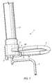
- FIG. 1is a perspective view of a portion of a hollow fiber filter comprising an end-cap assembly according to the invention
- FIG. 2is a perspective view of a second embodiment of an end-cap assembly according to the invention.
- FIG. 3is a cross-section view of the end-cap assembly of FIG. 2 ;
- FIG. 4is a perspective view of the end-cap assembly shown in FIGS. 2 and 3 fitted with a pump hose;
- FIG. 5is cross-section view of the end-cap assembly of FIGS. 2 to 4 mounted on an end of a hollow fiber filter;
- FIG. 6is a perspective view of a third embodiment of an end-cap assembly according to the invention.
- FIG. 7is a perspective view of a fourth embodiment of an end-cap assembly according to the invention.
- FIG. 8is a perspective view of a fifth embodiment of an end-cap assembly according to the invention.
- FIGS. 9 a and 9 bare perspective views of the two parts of the holder of the end-cap assembly of FIG. 8 ;
- FIGS. 10 a and 10 bare longitudinal cross section views of two embodiments of the tubular connector of the holder of the end-cap assembly of FIG. 8 ;
- FIGS. 11 a and 11 bare plan views of two arterial blood lines designed to equip the end-cap assembly of FIG. 8 ;
- FIG. 12is a longitudinal cross section view of a sixth embodiment of an end-cap assembly according to the invention.
- FIG. 1shows an end-cap assembly 1 mounted at one end of a tubular housing 2 of a filter.
- the end-cap assembly 1comprises an end-cap 3 having a slightly cambered circular end wall connected to a cylindrical peripheral wall by which the end-cap 3 is secured to the housing 2 of the filter.
- the circular end wall of the end-cap 3is substantially perpendicular to the longitudinal axis of the housing 2 , and the central axis 9 of the end-cap 3 coincides with the longitudinal axis of the housing 2 .
- the end-cap assembly 1further comprises a nozzle 8 made integral with the end-cap 3 so as to form an inlet port that gives access to the interior of the end-cap 3 , and a tubular holder 5 for an end of a pump hose 4 of a peristaltic pump.
- the tubular holder 5is secured to the nozzle 8 by welding or gluing or it can be formed integral with the nozzle 8 .
- the tubular holder 5has a larger section at one end for connection to a pump hose 4 and a smaller section at the other end for connection to a tube 7 forming the downstream part of the arterial blood line of an extracorporeal blood treatment system.
- the tubular holder 5is so positioned with respect to the nozzle 8 as to be further apart from the end-cap 3 than the nozzle 8 . It results from this arrangement that, when a first (or downstream) end 4 a of a pump hose 4 is connected to the inlet port 8 and the second (or upstream) end 4 b of the pump hose 4 is connected to the tubular holder 5 , the first end 4 a of the pump hose 4 is offset from the second end 4 b along the central axis 9 of the end-cap 3 .
- the end-cap assembly 1is in an operative position, i.e. at a lower point of a filter held vertical, the tubular holder 5 and the upstream end 4 b of a pump hose 4 are therefore lower than the nozzle 8 and the downstream end 4 a of the pump hose 4 .
- the inlet port 8 and the tubular holder 5are so positioned with respect to each other that when a first end 4 a of a pump hose 4 is connected to the inlet port 8 and the second end 4 b of the pump hose 4 is connected to the tubular holder 5 , the pump hose 4 forms a loop that extends in a plan that is slightly inclined with respect to a plan perpendicular to the central axis 9 of the end-cap assembly 1 . Since the tubular holder 5 is lower that the nozzle 8 when the end cap assembly 1 is in an operational position, this arrangement helps gas bubbles move though the hose into the filter and prevents the stagnation of gas bubbles in the pump hose 4 .
- a desired angle of inclination of the looped hose 4 with respect to a plane perpendicular to the central axis 9 of the end-cap assembly 1may be comprised between 3 to 7 degrees, and preferably be about 5 degrees.
- the looped pump hose 4is adapted to readily cooperate with a peristaltic pump of the rotary type upon connection of the filter to a treatment device (e.g. a dialysis machine).
- a rotary peristaltic pumpcomprises a rotor generally bearing two rollers at its periphery.
- the rotoris mounted in a support having a semi-circular wall that partially surrounds the rotor and defines a semi-annular gap in which the pump hose 4 can be received.
- the rollersalternately engage the pump hose 4 and squeeze it against the semicircular wall while moving along a circular path, thereby pushing the liquid contained in the pump hose 4 towards the downstream end 4 a of the hose.
- the end-cap assembly 1further comprises two Infusion/injection ports 6 a , 6 b connected to the tubular holder 5 , which can be used for the injection of various substances (e.g. heparin or a substitution solution) to the liquid (e.g. blood) flowing through the filter.
- various substancese.g. heparin or a substitution solution
- One of these portscan also be used as a pressure measurement port for connection to a pressure sensor for measuring the pressure of the liquid upstream of the pump hose 4 .
- the end-cap assembly 1also comprises a pressure measurement port 10 connected to the inlet port 8 for connection to a pressure sensor for measuring the pressure of the liquid entering the first compartment of the filter.
- FIGS. 2 to 4show a second embodiment of the end-cap assembly 1 of the invention.
- the end-cap assembly 1is represented without a pump hose connected thereto, whereas in FIGS. 4 and 5 a pump hose 4 is connected to the inlet port 8 and to the holder 5 , 23 .
- the end-cap 3comprises a circular end-wall portion 14 connected to a peripheral wall portion 12 that is designed for securing the end-cap 3 to the housing of a filter.
- the end-cap 3has a central axis 9 that coincides with the longitudinal axis of the tubular housing of a filter when the end-cap is mounted at one end of such a housing.
- the circular end wall portion 14 and the peripheral wall portion 12define an interior region 15 of the end-cap 3 .
- the interior region 15forms a header-chamber when the end-cap 3 is mounted at one end of the housing of a filter.
- the end-cap assembly 1 shown on FIGS. 2 to 5has an inlet port 8 that is eccentric with respect to the central axis 9 of the end-cap 3 and is formed integral with the end-wall 14 and of the end-cap 3 .
- the inlet port 8comprises a first (upstream) portion 18 furthest to the end wall 14 , a second (downstream) portion 19 closest to the end wall 14 , and an intermediate portion 20 connecting the first portion 18 to the second portion 19 .
- the first (upstream) portion 18is cylindrical and has a longitudinal axis slightly inclined with respect to a plane perpendicular to the central axis 9 of the end-cap 3 .
- the second (downstream) portion 19flares towards the interior 15 of the end-cap 3 along an axis generally parallel to the central axis 9 .
- the intermediate portion 20has a curvature 16 selected so as to facilitate a smooth an unimpeded flow of a liquid pumped into the end cap 3 .
- the downstream flaring portion 19also has a curvature 17 selected so as to evenly direct a liquid pumped into the end cap 3 towards the apertures of the hollow fibers 25 at the outer surface of a disk 26 of potting material, when the end-cap assembly is mounted at one end of a filter housing 2 ( FIG. 5 ).
- the geometry of the inlet port 8therefore ensures a smooth passage and distribution of a liquid therethrough and into the interior region 15 .
- the radius of the curvature 16 of the intermediate portion 20 and the radius of the curvature 17 of the second portion 19may be equal. A suitable value for both radii lies in the range of about 6 to 12 mm, preferably about 9 mm.
- the end-cap assembly 1further comprises a first holder for a pump hose 4 having a leg 23 protruding at the periphery of the end-cap 3 and a tubular connector 5 connected to the leg 23 so that the longitudinal axis of the tubular connector 5 is substantially parallel to a line tangential to the circular end wall portion 14 of the end-cap 3 . It results from this arrangement that the inlet port 8 and the tubular connector 5 are spaced apart with respect to the central axis 9 , both axially and longitudinally, the inlet port 8 being closer to the end-cap 3 than the connector 5 .
- a pump hose 4 connected to the tubular connector 5 and the inlet port 8forms a loop that is therefore slightly inclined with respect to a plan perpendicular to the central axis 9 , with the upstream end 4 b of the pump hose 4 lower than the downstream end 4 a of the pump hose 4 when the end cap assembly 1 is in an operational position as shown in FIG. 5 .
- a suitable angle of inclination for helping degas the pump hose 4 during the priming of a filteris in the range of 3 to 7 degrees, preferably 5 degrees.
- the first holder 5 , 23may be formed integral with the end-cap 3 , or it may be fixed to the end-cap 3 for example by bonding or by welding.
- the tubular connector 5comprises a first socket 21 of larger section at one end for connection to a pump hose 4 and a second socket 27 of a smaller section at the other end for connection to a tube (e.g. an arterial blood line).
- the socket 27can comprise a Luer connection element (not shown) for attachment to a tube fitted with a complementary Luer connection element.
- the connector 5also comprises two ports 6 a , 6 b that can be used for infusing a liquid into the filter or to measure the pressure in the liquid upstream of a peristaltic pump.
- the end-cap assembly represented in FIGS. 2 to 5further comprises a second holder 22 for the pump hose 4 comprising an arm extending outwards, from the periphery of the end-cap 3 , substantially opposite the first holder 5 , 23 with respect to the inlet port 8 .
- the second holder 22comprises a grip at its outer end for receiving and holding a portion of the pump hose 4 .
- the inlet port 8 and the second holder 22are so arranged with respect to each other that, when the first end 4 a of a pump hose 4 is secured to the inlet port 8 and the second end 4 b of the pump hose 4 is secured to the first holder 5 , 23 , the pump hose 4 has a first portion that extends straight from the inlet port 8 to the second holder 22 and a second U-shaped portion that extends from the second holder 22 to the first holder 5 , 23 . In this arrangement, the pump hose 4 is bent by the second holder 22 , just upstream of the second holder 22 ( FIG. 4 ).
- the second holder 22gives rigidity to the pump hose 4 and thereby facilitates the positioning of the pump hose 4 around the rotor of a peristaltic pump of a treatment machine.
- the second holder 22can be formed integral with the end-cap 3 , or it can be attached to the end-cap by e.g. bonding or welding.
- FIG. 5shows the end-cap assembly 1 of FIGS. 2 to 4 connected to the housing 2 of a hollow fiber filter.
- a liquidrepresented by arrows, flows through the pump hose 4 and enters via the inlet port 8 into the header chamber 15 of the filter, which is delimited by the interior surface of the end-cap 3 and the outer surface of a disk of potting material 26 in which one end of a bundle of hollow fibers 25 is embedded.
- FIG. 6shows a third embodiment of the end-cap assembly according to the invention.
- the first holder 5 , 23 of this end-cap assemblyis removable.
- the end-cap 3comprises a fixation element in the form of two parallel grooves 13
- the leg 23 of the holdercomprises a complementary fixation element in the form of two parallel tongues 11 designed to snugly fit in the grooves 13 when they are engaged therein.
- the tubular connector 5comprises three ports 6 a , 6 b , 6 c opening opposite the end-cap 3 , which can be used for injecting or infusing various liquids (e.g. heparin and a substitution solution) and for connection to a pressure sensor.
- various liquidse.g. heparin and a substitution solution
- the second holder 22is connected to the inlet port 8 and it comprises a curved portion that leads to a tubular clip 24 forming the outer end of the holder.
- the clip 24is resilient and can be opened so as to receive a portion of a pump hose that it snugly holds when closed.
- the curved portion of the second holder 22forms a partial cradle for a portion of pump hose when a pump hose is connected to the inlet port 8 ant to the tubular connector 5 , while passing through the clip 24 .
- the respective dimension and orientation of the inlet port 6 and the connector 5are such that they are spaced apart axially and longitudinally with respect to the central axis of the end-cap 3 , and that a pump hose connected thereto would form a loop slightly inclined with respect to a plane perpendicular to this central axis.
- FIG. 7shows a fourth embodiment of the end-cap assembly according to the invention.
- the end-cap 3comprises a tubular skirt to which an end portion of the inlet port 8 and of an end portion the holder 5 are connected so as to lie in a plane substantially perpendicular to the longitudinal axis of the filter.
- a pump hose 4is connected to the inlet port 8 and to the connector 5 and forms a loop that extends in the same plane.
- FIGS. 8 to 11 bshow a fifth embodiment of the end-cap assembly 1 according to the invention.
- the holderdoes not comprise a tubular connector as in the embodiments of FIGS. 2 to 6 , but instead its leg 23 is connected to and made integral with a resilient clip 50 having a C-shaped socket 51 .
- the clip 50has a longitudinal slit-like mouth 52 for allowing the engagement of a tubular connector 53 into the socket 51 .
- the connector 53has an outside diameter corresponding to the diameter of the C-shaped socket 51 and it comprises two circular end flanges 54 for preventing the connector 53 from longitudinally moving within the socket 51 when the connector 53 is engaged in the clip 50 .
- the tubular connector 53is connected to the second end 4 b of a pump hose 4 , the first end 4 a of which is either permanently connected to the inlet port 8 of the end-cap 3 or comprises a connecting element 4 c , for example of the Luer type, for connection to a complementary connecting element included in the outlet port 8 .
- the tubular connector 53can also be pre-connected to a tube 7 , as shown in FIGS. 10 a and 11 a , which represent an arterial blood line in which the tube 7 used for supplying blood from a patient to a hemodialyzer has a smaller diameter than the diameter of the pump hose 4 .
- the inner bore of the connector 53comprises a first end portion with a smaller diameter corresponding to the outer diameter of the tube 7 , a second end portion with a larger diameter corresponding to the outer diameter of the pump hose 4 and an intermediary portion flaring from the first end portion to the second end portion.
- the arterial blood linecomprises a connecting element at both ends, one of which is the connector element 4 c adapted to the inlet port 8 , the other connector element being designed for connection to a cannula.
- the internal bore of the connector 53is cylindrical and corresponds to the outer diameter of the pump hose 4 and the tube 7 that can be made of the same piece of tubing (see FIGS. 10 b and 11 b ).
- the connector 53is merely slipped on the piece of tubing before being glued thereto at the appropriate location.
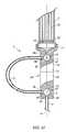
- FIG. 12shows a sixth embodiment of the end-cap assembly 1 according to the invention.
- This end-cap assemblysubstantially differs from the previously described embodiments in that it is designed to hold a pump hose 4 in a plane containing the central axis b of the end-cap 3 .
- FIG. 12represents an end portion of a filter having a tubular housing 2 containing a bundle of hollow fibers 25 secured to the housing 2 at the end thereof by a disk of potting material 26 in which the end of the fibers 25 are embedded.
- the housing 2is closed by an end-cap 3 having a circular end wall whose central axis 9 coincides with the longitudinal axis 9 of the housing 2 .
- a pump hose support 30in the form of an elongated rectangular parallelepiped is connected to the end-cap 3 so that the longitudinal axis of the support 30 coincides with the central axis 9 of the end-cap 3 .
- the pump hose support 30comprises two separate parts 31 and 32 that can be connected together by a mechanical coupling (not shown).
- the first part 31 of the pump hose support 30which can be made integral with the end-cap 3 , comprises a pressure measurement chamber 33 having a first and a second compartments separated by a flexible membrane 34 that lies in the plane of the figure.
- the first compartment of the pressure chamber 33communicates with the end-cap 3 through a first portion 8 a of an inlet port that extends along the central axis 9 of the end-cap 3 .
- the first compartment of the pressure chamber 33is also connected to the first end 4 a of a pump hose 4 through a second portion 8 b of the inlet port, whose longitudinal axis is perpendicular to the longitudinal axis 9 of the support 30 .
- the first compartment of the pressure measurement chamber 33can also be connected to a source of liquid (e.g. an infusion liquid) through a port 6 opposite to the second portion 8 b of the inlet port.
- a source of liquide.g. an infusion liquid
- the second compartment of the pressure measurement chamber 33comprises an aperture 10 for the connection to a pressure sensor for the measurement of the pressure of the liquid downstream of the pump hose 4 .
- the second part 32 of the pump hose support 30also comprises a pressure measurement chamber 37 having a first and a second compartments separated by a flexible membrane 38 that lies in the plane of the figure.
- the first compartment of the pressure chamber 37is connected to a supply tube 7 through a channel 39 that extends along the longitudinal axis of the pump hose support 30 .
- the first compartment of the pressure measurement chamber 37is also connected to the second end 4 b of the pump hose 4 through a channel 40 , whose longitudinal axis is perpendicular to the longitudinal axis of the support 30 .
- the first compartmentcan be connected to a source of liquid by a port 6 opposite to the channel 39 .
- the second compartment of the pressure measurement chamber 37comprises an aperture 10 for the connection to a pressure sensor for the measurement of the pressure of the liquid upstream of the pump hose 4 .
Landscapes
- Health & Medical Sciences (AREA)
- Heart & Thoracic Surgery (AREA)
- Engineering & Computer Science (AREA)
- Cardiology (AREA)
- Public Health (AREA)
- Animal Behavior & Ethology (AREA)
- Veterinary Medicine (AREA)
- General Health & Medical Sciences (AREA)
- Life Sciences & Earth Sciences (AREA)
- Anesthesiology (AREA)
- Biomedical Technology (AREA)
- Hematology (AREA)
- Vascular Medicine (AREA)
- Urology & Nephrology (AREA)
- Mechanical Engineering (AREA)
- Chemical & Material Sciences (AREA)
- Chemical Kinetics & Catalysis (AREA)
- Water Supply & Treatment (AREA)
- Emergency Medicine (AREA)
- Pulmonology (AREA)
- External Artificial Organs (AREA)
- Infusion, Injection, And Reservoir Apparatuses (AREA)
- Filtration Of Liquid (AREA)
Abstract
Description
- an end-cap having an end wall;
- an inlet port extending through the end wall for connection to a first end of a pump hose of a peristaltic pump; and
- a first holder for securing a second end of the pump hose,
wherein the inlet port and the first holder are arranged relative to each other so that the pump hose forms a loop when the first end the pump hose is connected to the inlet port and the second end of the pump hose is secured by the holder.
- The inlet port is offset with respect to a central axis of the end-cap.
- The inlet port comprises a first portion furthest to the end wall, a second portion closest to the end wall, and an intermediate portion connecting the first portion to the second portion, wherein the first portion has an axis slightly inclined with respect to a plane perpendicular to a central axis of the end-cap, the second portion flares towards an interior of the end-cap along an axis generally parallel to the central axis of the end-cap and the intermediate portion has a curvature adapted to facilitate a smooth an unimpeded flow of a liquid pumped into the end cap.
- The first holder comprises a tubular connector for connecting the pump hose to a tube.
- The first holder comprises a clip for snugly engaging a tubular connector for connecting the pump hose to a tube. The tubular connector is removable and the clip is designed to resiliently engage and lock the tubular connector.
- The end-cap assembly comprises at least one infusion port connected to the inlet port and a pressure measurement port connected to the inlet port for measuring a pressure of liquid downstream of the pump hose.
- The end-cap assembly comprises at least one infusion port connected to the first holder and a pressure measurement port connected to the first holder for measuring a pressure of liquid upstream of the pump hose.
Claims (25)
Applications Claiming Priority (5)
| Application Number | Priority Date | Filing Date | Title |
|---|---|---|---|
| EP03025640 | 2003-11-07 | ||
| EP03025640 | 2003-11-07 | ||
| EP03025640.8 | 2003-11-07 | ||
| EPPCT/EP2004/011707 | 2004-10-18 | ||
| PCT/EP2004/011707WO2005044428A1 (en) | 2003-11-07 | 2004-10-18 | End-cap assembly with pump hose for a filter and filter comprising such an end-cap assembly |
Related Parent Applications (1)
| Application Number | Title | Priority Date | Filing Date |
|---|---|---|---|
| PCT/EP2004/011707ContinuationWO2005044428A1 (en) | 2003-11-07 | 2004-10-18 | End-cap assembly with pump hose for a filter and filter comprising such an end-cap assembly |
Publications (2)
| Publication Number | Publication Date |
|---|---|
| US20090020468A1 US20090020468A1 (en) | 2009-01-22 |
| US8403150B2true US8403150B2 (en) | 2013-03-26 |
Family
ID=34560156
Family Applications (1)
| Application Number | Title | Priority Date | Filing Date |
|---|---|---|---|
| US11/379,725Active2027-11-09US8403150B2 (en) | 2003-11-07 | 2006-04-21 | End-cap assembly with pump hose for a filter and filter comprising such an end-cap assembly |
Country Status (10)
| Country | Link |
|---|---|
| US (1) | US8403150B2 (en) |
| EP (1) | EP1530995B1 (en) |
| KR (1) | KR101188573B1 (en) |
| CN (3) | CN100406108C (en) |
| AT (1) | ATE354429T1 (en) |
| AU (1) | AU2004286774B2 (en) |
| CA (1) | CA2543519C (en) |
| DE (1) | DE602004004857T2 (en) |
| ES (1) | ES2282775T3 (en) |
| WO (1) | WO2005044428A1 (en) |
Cited By (7)
| Publication number | Priority date | Publication date | Assignee | Title |
|---|---|---|---|---|
| US11712501B2 (en) | 2019-11-12 | 2023-08-01 | Fresenius Medical Care Deutschland Gmbh | Blood treatment systems |
| USD996211S1 (en)* | 2020-05-18 | 2023-08-22 | Illinois Tool Works Inc. | Sealant bottle cap |
| US11730871B2 (en) | 2019-11-12 | 2023-08-22 | Fresenius Medical Care Deutschland Gmbh | Blood treatment systems |
| US11752247B2 (en) | 2019-11-12 | 2023-09-12 | Fresenius Medical Care Deutschland Gmbh | Blood treatment systems |
| US11925736B2 (en) | 2019-11-12 | 2024-03-12 | Fresenius Medical Care Deutschland Gmbh | Blood treatment systems |
| US12285553B2 (en) | 2019-11-12 | 2025-04-29 | Fresenius Medical Care Deutschland Gmbh | Blood treatment systems |
| US12329890B2 (en) | 2019-11-12 | 2025-06-17 | Fresenius Medical Care Deutschland Gmbh | Blood treatment systems |
Families Citing this family (30)
| Publication number | Priority date | Publication date | Assignee | Title |
|---|---|---|---|---|
| EP2155287B1 (en)* | 2007-05-15 | 2017-10-04 | Gambro Lundia AB | Pressure sensing device and use of the same in a connecting structure |
| EP2113266A1 (en)* | 2008-04-30 | 2009-11-04 | Gambro Lundia AB | Degassing device |
| GB0812457D0 (en)* | 2008-07-08 | 2008-08-13 | Parker Hannifin U K Ltd | A Filter |
| DE102009038571B4 (en)* | 2009-08-22 | 2011-07-14 | Völker, Manfred, 63825 | Supply device for dialysis machines |
| US9228575B2 (en)* | 2010-11-16 | 2016-01-05 | Zoeller Pump Company, Llc | Sealed and self-contained tankless water heater flushing system |
| US9173987B2 (en)* | 2013-02-01 | 2015-11-03 | Medtronic, Inc. | Degassing module for a controlled compliant flow path |
| US9404488B2 (en)* | 2013-02-19 | 2016-08-02 | Wabtec Holding Corp. | Pressurized oil delivery system for a reciprocating air compressor |
| ES2691949T3 (en) | 2013-08-29 | 2018-11-29 | Sanofi | Safety device for a medicine container |
| KR102121918B1 (en)* | 2013-12-20 | 2020-06-11 | 삼성전자주식회사 | Method and apparatus for event notification in home network system |
| WO2017092795A1 (en)* | 2015-12-01 | 2017-06-08 | Ateliers Busch S.A. | Vacuum pump with filtering element |
| CN109715266B (en)* | 2016-10-20 | 2021-11-30 | Emd密理博公司 | Valve protection and pipeline management device |
| CA3066361A1 (en) | 2017-06-07 | 2018-12-13 | Shifamed Holdings, Llc | Intravascular fluid movement devices, systems, and methods of use |
| WO2019094963A1 (en) | 2017-11-13 | 2019-05-16 | Shifamed Holdings, Llc | Intravascular fluid movement devices, systems, and methods of use |
| CN112004563B (en) | 2018-02-01 | 2024-08-06 | 施菲姆德控股有限责任公司 | Intravascular blood pump and methods of use and manufacture |
| CN108295326B (en)* | 2018-02-09 | 2021-03-26 | 苏州卓壹医疗器械有限公司 | Double-cavity ultrapure hemodialyzer |
| JP6577626B1 (en)* | 2018-05-02 | 2019-09-18 | 日機装株式会社 | Air trap chamber and extracorporeal circuit |
| US12161857B2 (en) | 2018-07-31 | 2024-12-10 | Shifamed Holdings, Llc | Intravascular blood pumps and methods of use |
| WO2020073047A1 (en) | 2018-10-05 | 2020-04-09 | Shifamed Holdings, Llc | Intravascular blood pumps and methods of use |
| USD910081S1 (en)* | 2019-02-14 | 2021-02-09 | Fleece Performance Engineering, Inc. | Pump cap |
| USD910082S1 (en)* | 2019-04-17 | 2021-02-09 | Fleece Performance Engineering, Inc. | Pump cap |
| USD910083S1 (en)* | 2019-05-08 | 2021-02-09 | Fleece Performance Engineering, Inc. | Pump cap |
| WO2021011473A1 (en) | 2019-07-12 | 2021-01-21 | Shifamed Holdings, Llc | Intravascular blood pumps and methods of manufacture and use |
| US11654275B2 (en) | 2019-07-22 | 2023-05-23 | Shifamed Holdings, Llc | Intravascular blood pumps with struts and methods of use and manufacture |
| US12121713B2 (en) | 2019-09-25 | 2024-10-22 | Shifamed Holdings, Llc | Catheter blood pumps and collapsible blood conduits |
| EP4501393A3 (en) | 2019-09-25 | 2025-04-09 | Shifamed Holdings, LLC | Catheter blood pumps and collapsible pump housings |
| WO2021062265A1 (en) | 2019-09-25 | 2021-04-01 | Shifamed Holdings, Llc | Intravascular blood pump systems and methods of use and control thereof |
| EP4072650A4 (en) | 2019-12-11 | 2024-01-10 | Shifamed Holdings, LLC | Descending aorta and vena cava blood pumps |
| EP3900814B1 (en)* | 2020-04-23 | 2025-07-30 | Bellco S.r.l. | Dialyzer header cap |
| USD985632S1 (en)* | 2021-06-30 | 2023-05-09 | Fleece Performance Engineering, Inc. | Pump cap |
| CN118767235A (en)* | 2024-06-24 | 2024-10-15 | 恩基(苏州)智慧医疗科技有限公司 | A quick-change hemodialysis dialysis machine |
Citations (46)
| Publication number | Priority date | Publication date | Assignee | Title |
|---|---|---|---|---|
| US4227420A (en) | 1979-06-11 | 1980-10-14 | Baxter Travenol Laboratories, Inc. | Pressure coupling mechanism in a pressure monitoring assembly |
| US4231871A (en) | 1977-06-10 | 1980-11-04 | Cordis Dow Corp. | Artificial kidney and method for making same |
| US4263808A (en) | 1979-03-26 | 1981-04-28 | Baxter Travenol Laboratories, Inc. | Noninvasive pressure monitor |
| US4287059A (en) | 1978-06-15 | 1981-09-01 | Honda Giken Kogyo Kabushiki Kaisha | Dialyzer apparatus in an artificial kidney system |
| US4293413A (en) | 1979-12-28 | 1981-10-06 | Baxter Travenol Laboratories, Inc. | Dialyzer blood circuit and bubble traps |
| US4344777A (en) | 1980-01-07 | 1982-08-17 | Siposs George G | Directed flow bubble trap for arterial blood |
| US4345999A (en) | 1978-04-27 | 1982-08-24 | Dr. Eduard Fresenius, Chemisch-Pharmazeutische Industrie K.G., Apparatebau K.G. | Apparatus for preventing the entry of air into an artificial organ |
| US4368118A (en) | 1980-01-07 | 1983-01-11 | Siposs George G | Blood-air separator and filter |
| FR2513884A1 (en) | 1981-10-06 | 1983-04-08 | Elmar Medical Systems Ltd | EXTRA-BODY BLOOD TREATMENT APPARATUS |
| US4379452A (en) | 1977-10-18 | 1983-04-12 | Baxter Travenol Laboratories, Inc. | Prepackaged, self-contained fluid circuit module |
| US4412916A (en) | 1981-06-24 | 1983-11-01 | Cordis Dow Corp. | Airless artificial kidney assembly |
| US4433971A (en) | 1981-06-30 | 1984-02-28 | Minnesota Mining And Manufacturing Company | Integrated cardioplegia delivery system |
| US4436620A (en) | 1977-05-09 | 1984-03-13 | Baxter Travenol Laboratories, Inc. | Integral hydraulic circuit for hemodialysis apparatus |
| US4479762A (en) | 1982-12-28 | 1984-10-30 | Baxter Travenol Laboratories, Inc. | Prepackaged fluid processing module having pump and valve elements operable in response to applied pressures |
| US4479761A (en) | 1982-12-28 | 1984-10-30 | Baxter Travenol Laboratories, Inc. | Actuator apparatus for a prepackaged fluid processing module having pump and valve elements operable in response to externally applied pressures |
| US4479760A (en) | 1982-12-28 | 1984-10-30 | Baxter Travenol Laboratories, Inc. | Actuator apparatus for a prepackaged fluid processing module having pump and valve elements operable in response to applied pressures |
| US4493693A (en) | 1982-07-30 | 1985-01-15 | Baxter Travenol Laboratories, Inc. | Trans-membrane pressure monitoring system |
| US4582598A (en) | 1981-12-15 | 1986-04-15 | Baxter Travenol Laboratories, Inc. | Replacement fluid control system for a blood fractionation apparatus and the like |
| US4605503A (en) | 1983-05-26 | 1986-08-12 | Baxter Travenol Laboratories, Inc. | Single needle blood fractionation system having adjustable recirculation through filter |
| US4617115A (en) | 1980-10-06 | 1986-10-14 | Hospal Industrie | Artificial kidney with disposable dialysis liquid circuit |
| US4623450A (en) | 1981-06-16 | 1986-11-18 | Hospal Industrie | Artificial kidney |
| US4666598A (en) | 1985-06-25 | 1987-05-19 | Cobe Laboratories, Inc. | Apparatus for use with fluid flow transfer device |
| US4676467A (en) | 1985-10-31 | 1987-06-30 | Cobe Laboratories, Inc. | Apparatus for supporting a fluid flow cassette |
| EP0245782A2 (en) | 1986-05-12 | 1987-11-19 | DIDECO S.p.A. | Device for filtering arterial blood |
| US4765888A (en) | 1980-11-13 | 1988-08-23 | Hospal Industrie | Artificial kidney with integrated dialysate circuit |
| EP0292445A1 (en) | 1987-05-18 | 1988-11-23 | SORIN BIOMEDICA S.p.A. | Hollow-fibre oxygenation device |
| US4798090A (en) | 1985-06-25 | 1989-01-17 | Cobe Laboratories, Inc. | Apparatus for use with fluid flow transfer device |
| US4806135A (en) | 1988-03-01 | 1989-02-21 | Siposs George G | Bubble trap for phase-separating gas bubbles from flowing liquids |
| US4824339A (en) | 1987-08-19 | 1989-04-25 | Cobe Laboratories, Inc. | Peristaltic pump cartridge |
| DE4027531C1 (en) | 1990-08-31 | 1991-07-25 | Fresenius Ag, 6380 Bad Homburg, De | Filter for sterilising aq. soln. e.g. dialysis liq. - where incoming liq. flows between 1st antechamber, and fibre interiors into 2nd antechamber |
| US5130020A (en)* | 1990-08-30 | 1992-07-14 | Meckstroth Alan F | Portable water filter unit having storage space for flexible tubes |
| US5200090A (en) | 1990-03-30 | 1993-04-06 | Baxter International Inc. | Multiple fluid source isolation, metering and alarm system and method |
| EP0591896A2 (en) | 1992-10-05 | 1994-04-13 | Minnesota Mining And Manufacturing Company | Membrane blood oxygenator |
| US5441636A (en) | 1993-02-12 | 1995-08-15 | Cobe Laboratories, Inc. | Integrated blood treatment fluid module |
| US5468388A (en) | 1993-07-01 | 1995-11-21 | Sartorius Ag | Filter module with degassing feature |
| US5707431A (en) | 1994-02-15 | 1998-01-13 | Sims Level 1, Inc. | Vortex gas elimination device |
| US5744047A (en) | 1990-07-27 | 1998-04-28 | Pall Corporation | Leucocyte depleting filter device and method of use |
| US5849065A (en) | 1996-04-27 | 1998-12-15 | Fresenius Ag | Device for separating gas bubbles from fluids, in particular blood |
| WO2000025843A1 (en) | 1998-11-02 | 2000-05-11 | Lifestream International, Inc. | Cardioplegia heat exchanger |
| US6176903B1 (en) | 1996-05-22 | 2001-01-23 | Fresenius Medical Care Deutschland Gmbh | Device for removing gases from fluids |
| US6206954B1 (en) | 1998-05-13 | 2001-03-27 | Dsu Medical Corporation | Blood set and chamber |
| US6361518B1 (en) | 1995-06-07 | 2002-03-26 | Gambro Inc. | Extracorporeal blood processing methods and apparatus |
| US6582386B2 (en) | 2001-03-06 | 2003-06-24 | Baxter International Inc. | Multi-purpose, automated blood and fluid processing systems and methods |
| US20030138349A1 (en) | 1998-10-16 | 2003-07-24 | Mission Medical, Inc. | Blood processing system |
| USD479320S1 (en) | 2002-04-03 | 2003-09-02 | Chf Solutions, Inc. | Blood filter and tubing harness for extracorporeal blood treatment |
| US20070181488A1 (en)* | 2003-04-11 | 2007-08-09 | Gambro Lundia Ab | Method for Making A Filter Device Having More Than One Filtration Compartment |
Family Cites Families (5)
| Publication number | Priority date | Publication date | Assignee | Title |
|---|---|---|---|---|
| US4770787A (en)* | 1985-06-25 | 1988-09-13 | Cobe Laboratories, Inc. | Method of operating a fluid flow transfer device |
| IE904066A1 (en)* | 1989-11-13 | 1991-05-22 | Davol Inc | Blood pumping and processing system |
| US7041076B1 (en)* | 1999-09-03 | 2006-05-09 | Baxter International Inc. | Blood separation systems and methods using a multiple function pump station to perform different on-line processing tasks |
| DE10007327A1 (en)* | 2000-02-17 | 2001-08-30 | Fresenius Medical Care De Gmbh | Filter device, preferably hollow fiber dialyzer with curled hollow fibers |
| MXPA03007068A (en)* | 2001-02-07 | 2003-11-18 | Nephros Inc | Method and apparatus for a hemodiafiltration delivery module. |
- 2004
- 2004-10-18ATAT04024751Tpatent/ATE354429T1/ennot_activeIP Right Cessation
- 2004-10-18AUAU2004286774Apatent/AU2004286774B2/ennot_activeCeased
- 2004-10-18KRKR1020067008417Apatent/KR101188573B1/ennot_activeExpired - Fee Related
- 2004-10-18CACA2543519Apatent/CA2543519C/ennot_activeExpired - Fee Related
- 2004-10-18CNCNB2004800323430Apatent/CN100406108C/ennot_activeExpired - Fee Related
- 2004-10-18ESES04024751Tpatent/ES2282775T3/ennot_activeExpired - Lifetime
- 2004-10-18WOPCT/EP2004/011707patent/WO2005044428A1/enactiveApplication Filing
- 2004-10-18EPEP04024751Apatent/EP1530995B1/ennot_activeExpired - Lifetime
- 2004-10-18DEDE602004004857Tpatent/DE602004004857T2/ennot_activeExpired - Lifetime
- 2004-10-29CNCN2004800323411Apatent/CN1874804B/ennot_activeExpired - Fee Related
- 2004-11-05CNCN200480032345Apatent/CN100586494C/ennot_activeExpired - Fee Related
- 2006
- 2006-04-21USUS11/379,725patent/US8403150B2/enactiveActive
Patent Citations (46)
| Publication number | Priority date | Publication date | Assignee | Title |
|---|---|---|---|---|
| US4436620A (en) | 1977-05-09 | 1984-03-13 | Baxter Travenol Laboratories, Inc. | Integral hydraulic circuit for hemodialysis apparatus |
| US4231871A (en) | 1977-06-10 | 1980-11-04 | Cordis Dow Corp. | Artificial kidney and method for making same |
| US4379452A (en) | 1977-10-18 | 1983-04-12 | Baxter Travenol Laboratories, Inc. | Prepackaged, self-contained fluid circuit module |
| US4345999A (en) | 1978-04-27 | 1982-08-24 | Dr. Eduard Fresenius, Chemisch-Pharmazeutische Industrie K.G., Apparatebau K.G. | Apparatus for preventing the entry of air into an artificial organ |
| US4287059A (en) | 1978-06-15 | 1981-09-01 | Honda Giken Kogyo Kabushiki Kaisha | Dialyzer apparatus in an artificial kidney system |
| US4263808A (en) | 1979-03-26 | 1981-04-28 | Baxter Travenol Laboratories, Inc. | Noninvasive pressure monitor |
| US4227420A (en) | 1979-06-11 | 1980-10-14 | Baxter Travenol Laboratories, Inc. | Pressure coupling mechanism in a pressure monitoring assembly |
| US4293413A (en) | 1979-12-28 | 1981-10-06 | Baxter Travenol Laboratories, Inc. | Dialyzer blood circuit and bubble traps |
| US4344777A (en) | 1980-01-07 | 1982-08-17 | Siposs George G | Directed flow bubble trap for arterial blood |
| US4368118A (en) | 1980-01-07 | 1983-01-11 | Siposs George G | Blood-air separator and filter |
| US4617115A (en) | 1980-10-06 | 1986-10-14 | Hospal Industrie | Artificial kidney with disposable dialysis liquid circuit |
| US4765888A (en) | 1980-11-13 | 1988-08-23 | Hospal Industrie | Artificial kidney with integrated dialysate circuit |
| US4623450A (en) | 1981-06-16 | 1986-11-18 | Hospal Industrie | Artificial kidney |
| US4412916A (en) | 1981-06-24 | 1983-11-01 | Cordis Dow Corp. | Airless artificial kidney assembly |
| US4433971A (en) | 1981-06-30 | 1984-02-28 | Minnesota Mining And Manufacturing Company | Integrated cardioplegia delivery system |
| FR2513884A1 (en) | 1981-10-06 | 1983-04-08 | Elmar Medical Systems Ltd | EXTRA-BODY BLOOD TREATMENT APPARATUS |
| US4582598A (en) | 1981-12-15 | 1986-04-15 | Baxter Travenol Laboratories, Inc. | Replacement fluid control system for a blood fractionation apparatus and the like |
| US4493693A (en) | 1982-07-30 | 1985-01-15 | Baxter Travenol Laboratories, Inc. | Trans-membrane pressure monitoring system |
| US4479760A (en) | 1982-12-28 | 1984-10-30 | Baxter Travenol Laboratories, Inc. | Actuator apparatus for a prepackaged fluid processing module having pump and valve elements operable in response to applied pressures |
| US4479761A (en) | 1982-12-28 | 1984-10-30 | Baxter Travenol Laboratories, Inc. | Actuator apparatus for a prepackaged fluid processing module having pump and valve elements operable in response to externally applied pressures |
| US4479762A (en) | 1982-12-28 | 1984-10-30 | Baxter Travenol Laboratories, Inc. | Prepackaged fluid processing module having pump and valve elements operable in response to applied pressures |
| US4605503A (en) | 1983-05-26 | 1986-08-12 | Baxter Travenol Laboratories, Inc. | Single needle blood fractionation system having adjustable recirculation through filter |
| US4666598A (en) | 1985-06-25 | 1987-05-19 | Cobe Laboratories, Inc. | Apparatus for use with fluid flow transfer device |
| US4798090A (en) | 1985-06-25 | 1989-01-17 | Cobe Laboratories, Inc. | Apparatus for use with fluid flow transfer device |
| US4676467A (en) | 1985-10-31 | 1987-06-30 | Cobe Laboratories, Inc. | Apparatus for supporting a fluid flow cassette |
| EP0245782A2 (en) | 1986-05-12 | 1987-11-19 | DIDECO S.p.A. | Device for filtering arterial blood |
| EP0292445A1 (en) | 1987-05-18 | 1988-11-23 | SORIN BIOMEDICA S.p.A. | Hollow-fibre oxygenation device |
| US4824339A (en) | 1987-08-19 | 1989-04-25 | Cobe Laboratories, Inc. | Peristaltic pump cartridge |
| US4806135A (en) | 1988-03-01 | 1989-02-21 | Siposs George G | Bubble trap for phase-separating gas bubbles from flowing liquids |
| US5200090A (en) | 1990-03-30 | 1993-04-06 | Baxter International Inc. | Multiple fluid source isolation, metering and alarm system and method |
| US5744047A (en) | 1990-07-27 | 1998-04-28 | Pall Corporation | Leucocyte depleting filter device and method of use |
| US5130020A (en)* | 1990-08-30 | 1992-07-14 | Meckstroth Alan F | Portable water filter unit having storage space for flexible tubes |
| DE4027531C1 (en) | 1990-08-31 | 1991-07-25 | Fresenius Ag, 6380 Bad Homburg, De | Filter for sterilising aq. soln. e.g. dialysis liq. - where incoming liq. flows between 1st antechamber, and fibre interiors into 2nd antechamber |
| EP0591896A2 (en) | 1992-10-05 | 1994-04-13 | Minnesota Mining And Manufacturing Company | Membrane blood oxygenator |
| US5441636A (en) | 1993-02-12 | 1995-08-15 | Cobe Laboratories, Inc. | Integrated blood treatment fluid module |
| US5468388A (en) | 1993-07-01 | 1995-11-21 | Sartorius Ag | Filter module with degassing feature |
| US5707431A (en) | 1994-02-15 | 1998-01-13 | Sims Level 1, Inc. | Vortex gas elimination device |
| US6361518B1 (en) | 1995-06-07 | 2002-03-26 | Gambro Inc. | Extracorporeal blood processing methods and apparatus |
| US5849065A (en) | 1996-04-27 | 1998-12-15 | Fresenius Ag | Device for separating gas bubbles from fluids, in particular blood |
| US6176903B1 (en) | 1996-05-22 | 2001-01-23 | Fresenius Medical Care Deutschland Gmbh | Device for removing gases from fluids |
| US6206954B1 (en) | 1998-05-13 | 2001-03-27 | Dsu Medical Corporation | Blood set and chamber |
| US20030138349A1 (en) | 1998-10-16 | 2003-07-24 | Mission Medical, Inc. | Blood processing system |
| WO2000025843A1 (en) | 1998-11-02 | 2000-05-11 | Lifestream International, Inc. | Cardioplegia heat exchanger |
| US6582386B2 (en) | 2001-03-06 | 2003-06-24 | Baxter International Inc. | Multi-purpose, automated blood and fluid processing systems and methods |
| USD479320S1 (en) | 2002-04-03 | 2003-09-02 | Chf Solutions, Inc. | Blood filter and tubing harness for extracorporeal blood treatment |
| US20070181488A1 (en)* | 2003-04-11 | 2007-08-09 | Gambro Lundia Ab | Method for Making A Filter Device Having More Than One Filtration Compartment |
Non-Patent Citations (7)
| Title |
|---|
| EPO, European Search Report, Application No. 1529545, Published Jun. 1, 2005, 3pgs. |
| EPO, European Search Report, Application No. 1530995, Published May 18, 2005, 2pgs. |
| EPO, European Search Report, Application No. 1532994, Published May 25, 2005, 3pgs. |
| WIPO, International Search Report, for PCT No. PCT/EP2004/011707 Published May 19, 2005, 2pgs. |
| WIPO, International Search Report, for PCT No. PCT/EP2004/012277, Published May 19, 2005, 3pgs. |
| WIPO, International Search Report, for PCT No. PCT/EP2004/012372 Published Jun. 16, 2005, 3pgs. |
| WIPO, International Search Report, for PCT No. PCT/EP2004/012528 Published May 19, 2005, 4pgs. |
Cited By (7)
| Publication number | Priority date | Publication date | Assignee | Title |
|---|---|---|---|---|
| US11712501B2 (en) | 2019-11-12 | 2023-08-01 | Fresenius Medical Care Deutschland Gmbh | Blood treatment systems |
| US11730871B2 (en) | 2019-11-12 | 2023-08-22 | Fresenius Medical Care Deutschland Gmbh | Blood treatment systems |
| US11752247B2 (en) | 2019-11-12 | 2023-09-12 | Fresenius Medical Care Deutschland Gmbh | Blood treatment systems |
| US11925736B2 (en) | 2019-11-12 | 2024-03-12 | Fresenius Medical Care Deutschland Gmbh | Blood treatment systems |
| US12285553B2 (en) | 2019-11-12 | 2025-04-29 | Fresenius Medical Care Deutschland Gmbh | Blood treatment systems |
| US12329890B2 (en) | 2019-11-12 | 2025-06-17 | Fresenius Medical Care Deutschland Gmbh | Blood treatment systems |
| USD996211S1 (en)* | 2020-05-18 | 2023-08-22 | Illinois Tool Works Inc. | Sealant bottle cap |
Also Published As
| Publication number | Publication date |
|---|---|
| KR20060113686A (en) | 2006-11-02 |
| EP1530995B1 (en) | 2007-02-21 |
| KR101188573B1 (en) | 2012-10-05 |
| CN100406108C (en) | 2008-07-30 |
| CN1874804A (en) | 2006-12-06 |
| CN1874837A (en) | 2006-12-06 |
| US20090020468A1 (en) | 2009-01-22 |
| EP1530995A1 (en) | 2005-05-18 |
| CN1874804B (en) | 2010-08-25 |
| AU2004286774A1 (en) | 2005-05-19 |
| ATE354429T1 (en) | 2007-03-15 |
| DE602004004857D1 (en) | 2007-04-05 |
| AU2004286774B2 (en) | 2010-12-02 |
| ES2282775T3 (en) | 2007-10-16 |
| CA2543519C (en) | 2012-12-11 |
| WO2005044428A1 (en) | 2005-05-19 |
| CN1874805A (en) | 2006-12-06 |
| DE602004004857T2 (en) | 2007-10-25 |
| CA2543519A1 (en) | 2005-05-19 |
| CN100586494C (en) | 2010-02-03 |
| HK1097792A1 (en) | 2007-07-06 |
Similar Documents
| Publication | Publication Date | Title |
|---|---|---|
| US8403150B2 (en) | End-cap assembly with pump hose for a filter and filter comprising such an end-cap assembly | |
| CA2543504C (en) | Integrated blood treatment module | |
| JP3784071B2 (en) | Dialysis blood piping set | |
| US11246972B2 (en) | Universal portable machine for online hemodiafiltration using regenerated dialysate | |
| CA2544612C (en) | Degassing device and end-cap assembly for a filter including such a degassing device | |
| US7993516B2 (en) | Integrated blood treatment module and extracorporeal blood treatment apparatus | |
| JPH0415698B2 (en) | ||
| HK1097792B (en) | End-cap assembly with pump hose for a filter and filter comprising such an end-cap assembly | |
| HK1097784B (en) | Fluid distribution module and extracorporeal blood circuit including such a module |
Legal Events
| Date | Code | Title | Description |
|---|---|---|---|
| AS | Assignment | Owner name:GAMBRO LUNDIA AB, SWEDEN Free format text:ASSIGNMENT OF ASSIGNORS INTEREST;ASSIGNORS:DANNENMAIER, JURGEN;SEIDLER, BJORN FREDERIK;JONSSON, LENNART;AND OTHERS;REEL/FRAME:021516/0722;SIGNING DATES FROM 20080606 TO 20080622 Owner name:GAMBRO LUNDIA AB, SWEDEN Free format text:ASSIGNMENT OF ASSIGNORS INTEREST;ASSIGNORS:DANNENMAIER, JURGEN;SEIDLER, BJORN FREDERIK;JONSSON, LENNART;AND OTHERS;SIGNING DATES FROM 20080606 TO 20080622;REEL/FRAME:021516/0722 | |
| AS | Assignment | Owner name:CITICORP TRUSTEE COMPANY LIMITED, UNITED KINGDOM Free format text:IP SECURITY AGREEMENT SUPPLEMENT;ASSIGNOR:GAMBRO LUNDIA AB;REEL/FRAME:022714/0702 Effective date:20090331 Owner name:CITICORP TRUSTEE COMPANY LIMITED,UNITED KINGDOM Free format text:IP SECURITY AGREEMENT SUPPLEMENT;ASSIGNOR:GAMBRO LUNDIA AB;REEL/FRAME:022714/0702 Effective date:20090331 | |
| AS | Assignment | Owner name:GAMBRO LUNDIA AB, COLORADO Free format text:RELEASE OF SECURITY INTEREST IN PATENTS;ASSIGNOR:CITICORP TRUSTEE COMPANY LIMITED, AS SECURITY AGENT;REEL/FRAME:027456/0050 Effective date:20111207 | |
| FEPP | Fee payment procedure | Free format text:PAYOR NUMBER ASSIGNED (ORIGINAL EVENT CODE: ASPN); ENTITY STATUS OF PATENT OWNER: LARGE ENTITY | |
| STCF | Information on status: patent grant | Free format text:PATENTED CASE | |
| FPAY | Fee payment | Year of fee payment:4 | |
| MAFP | Maintenance fee payment | Free format text:PAYMENT OF MAINTENANCE FEE, 8TH YEAR, LARGE ENTITY (ORIGINAL EVENT CODE: M1552); ENTITY STATUS OF PATENT OWNER: LARGE ENTITY Year of fee payment:8 | |
| MAFP | Maintenance fee payment | Free format text:PAYMENT OF MAINTENANCE FEE, 12TH YEAR, LARGE ENTITY (ORIGINAL EVENT CODE: M1553); ENTITY STATUS OF PATENT OWNER: LARGE ENTITY Year of fee payment:12 |